SINUMERIK 840D/840Di/810D Operator Components
SINUMERIK 840D/840Di/810D Operator Components
SINUMERIK 840D/840Di/810D Operator Components
- No tags were found...

Create successful ePaper yourself
Turn your PDF publications into a flip-book with our unique Google optimized e-Paper software.
OP 030 1OP 032S 2OP 010 3OP 010S 4<strong>SINUMERIK</strong> <strong>840D</strong>/<strong>840D</strong>i/<strong>810D</strong><strong>Operator</strong> <strong>Components</strong>ManualOP 010C 5OP 012 6Touch Panel TP 012 7OP 015 8OP 015A 915” TFT 10Component PCU 20 11Component PCU 50 12Component PCU 70 13Distributed Installation 14<strong>Operator</strong> ComponentPP 012 15PP 031 MC 16QWERTY Keyboard 17Valid forControlSoftware version<strong>SINUMERIK</strong> <strong>840D</strong> 6<strong>SINUMERIK</strong> <strong>840D</strong>E (export variant) 6<strong>SINUMERIK</strong> <strong>840D</strong> powerline 6<strong>SINUMERIK</strong> <strong>840D</strong>E powerline 6<strong>SINUMERIK</strong> <strong>840D</strong>i 2<strong>SINUMERIK</strong> <strong>840D</strong>iE (export variant) 2<strong>SINUMERIK</strong> <strong>810D</strong> 3<strong>SINUMERIK</strong> <strong>810D</strong>E (export variant) 3<strong>SINUMERIK</strong> <strong>810D</strong> powerline 6<strong>SINUMERIK</strong> <strong>810D</strong>E powerline 6PCI Adapter 18Floppy Disk Drive 19Machine Control Panel 20Handheld Unit 21Mini Handheld Unit 22Handheld Terminal HT 6 23Heat Dissipation 24Connection Conditions 2511.2002 EditionAppendixA
PrefaceNotes for theReaderThe <strong>SINUMERIK</strong> documentation is organized on three levels:General documentationUser documentation Manufacturer/service documentation.For more detailed information on <strong>SINUMERIK</strong> <strong>840D</strong>/<strong>810D</strong>/FM-NC publicationsand other publications covering all <strong>SINUMERIK</strong> controls, please contact yourlocal Siemens office.HotlineIf you have queries regarding the control system, please contact the followinghotline:A&D Technical Support Phone: ++49-(0)180-5050-222Fax: ++49-(0)180-5050-223Email: adsupport@siemens.comIf you have queries regarding documentation (suggestions, corrections), pleasesend a fax to the following fax address:Fax: ++49-(0)9131-98-2176Email: motioncontrol.docu@erlf.siemens.deFax form: See the feedback page at the end of the documentInternet addressfor <strong>SINUMERIK</strong>http://www.ad.siemens.de/sinumerik<strong>SINUMERIK</strong> <strong>840D</strong>powerlineImproved-performance variants<strong>SINUMERIK</strong> <strong>840D</strong> powerline and <strong>SINUMERIK</strong> <strong>840D</strong>E powerlinewill be available from 09.2001 onwards. For a list of available powerlinemodules, please refer to Section 1.1 of the Hardware Description /PHD/.<strong>SINUMERIK</strong> <strong>810D</strong>powerlineImproved-performance variants<strong>SINUMERIK</strong> <strong>810D</strong> powerline and <strong>SINUMERIK</strong> <strong>810D</strong>E powerlinewill be available from 12.2001 onwards. For a list of available powerlinemodules, please refer to Section 1.1 of the Hardware Description /PHC/.SpecifiedSW versionThe SW versions specified in the documentation refer to the <strong>SINUMERIK</strong> <strong>840D</strong>and <strong>SINUMERIK</strong> <strong>810D</strong> control systems. The software versions are related toeach other, see Table 1.1.© Siemens AG, 2002. All rights reserved<strong>SINUMERIK</strong> <strong>840D</strong>/<strong>840D</strong>i/<strong>810D</strong> <strong>Operator</strong> <strong>Components</strong> Manual (BH) – 11.02 Editionv
11.02 10.00Table 1-1Corresponding SW version<strong>SINUMERIK</strong> <strong>840D</strong> <strong>SINUMERIK</strong> <strong>810D</strong> <strong>SINUMERIK</strong> <strong>810D</strong>powerline<strong>SINUMERIK</strong> <strong>840D</strong>i6.3 (09.01) corresponds to – 6.1 (12.01) 2.1 (07.01)5.3 (04.00) corresponds to 3.3 (04.00) – 1.1 (07.00)3.7 (03.97) corresponds to 1.7 (03.97) – –Target readership? Configuring engineers Electricians and fitters Servicing and operating personnelContent of thismanualThe information contained in this manual explains how to install the operatorcomponents for the <strong>840D</strong> numerical controls and describes how to maintain andservice them.Safety andwarning conceptThe following safety and warning information is used in this document. Thesymbols used and their meaning are explained below.DangerIndicates an imminently hazardous situation which, if not avoided, will result indeath or serious injury or in substantial property damage.WarningIndicates a potentially hazardous situation which, if not avoided, could result indeath or serious injury or in substantial property damage.CautionUsed with the safety alert symbol indicates a potentially hazardous situationwhich, if not avoided, may result in minor or moderate injury or in property damage.CautionUsed without safety alert symbol indicates a potentially hazardous situationwhich, if not avoided, may result in property damage.vi© Siemens AG, 2002. All rights reserved<strong>SINUMERIK</strong> <strong>840D</strong>/<strong>840D</strong>i/<strong>810D</strong> <strong>Operator</strong> <strong>Components</strong> Manual (BH) – 11.02 Edition
10.00 11.02NoticeUsed without the safety alert symbol indicates a potential situation which, if notavoided, may result in an undesirable result or state.Other informationThe symbols used for other information are explained below.ImportantImportant indicates an important or especially relevant item of information.NoteNote refers to an important item of information about the product, handling ofthe product or part of the documentation which is particularly relevant in thecurrent context.Machine ManufacturerThis symbol appears in this documentation whenever the machine manufacturercan influence or modify the described functional behavior. Please observethe information provided by the machine manufacturer.Warnings andsafety informationTo safeguard your own personal safety as well as protect the product describedand all connected equipment and machines against damage, please read andobserve the following warnings and safety information.WarningOperational electrical equipment has parts and components which are athazardous voltage levels.Allowing unqualified persons access to the equipment/system or failure toheed the safety information could result in serious physical injury or substantialproperty damage. Only properly qualified personnel who have been trained toerect, install, start up or operate the product should be allowed to work on theequipment/system.Should it be necessary to test or take measurements on live equipment, thenthe specifications and procedures defined in Accident Prevention RegulationVBG 4.0 must be adhered to, in particular § 8 “Permissible deviations whenworking on live components”. Suitable electric tools must be used.© Siemens AG, 2002. All rights reserved<strong>SINUMERIK</strong> <strong>840D</strong>/<strong>840D</strong>i/<strong>810D</strong> <strong>Operator</strong> <strong>Components</strong> Manual (BH) – 11.02 Editionvii
11.02 10.00WarningRepairs to equipment supplied by Siemens must always be carried out bySIEMENS after-sales service personnel or by repair centers authorizedby SIEMENS. Parts or components must always be replaced by parts orcomponents specified in the spare parts list.Always disconnect the power supply before you open the unit.EMERGENCY STOP devices in compliance with EN 60204 IEC 204 (VDE0113) must remain operative in all operating modes of the automation device.Resetting the EMERGENCY STOP device must not result in any uncontrolledor undefined system restart.Wherever faults in the automation device have the potential to cause substantialmaterial damage or even human injury, i.e. they can present a danger,additional external precautions must be taken or devices providedwhich will guarantee or enforce a safe operating state in the event of a fault(e.g. through independent limit value switches, mech. interlocks, etc.).Caution Connecting and signal leads must be installed such that inductive and capacitiveinterference cannot impair automation functions.viii© Siemens AG, 2002. All rights reserved<strong>SINUMERIK</strong> <strong>840D</strong>/<strong>840D</strong>i/<strong>810D</strong> <strong>Operator</strong> <strong>Components</strong> Manual (BH) – 11.02 Edition
11.02 10.00ESDS instructions<strong>Components</strong> which can be destroyed by ElectroStatic DischargeImportantHandling ESDS boards: When handling components which can be destroyed by electrostatic discharge,it must be ensured that personnel, the workstation and packagingare well grounded.As a general rule, electronic boards should only be touched when absolutelynecessary. Never hold PCBs in such a way that you touch the modulepins or printed conductors.You may only touch ESDS components if– you are continuously grounded via an ESDS bracelet,– you are wearing ESDS shoes or ESDS shoe grounding strips in conjunctionwith an ESDS floor surface.Boards may only be placed on conductive surfaces (desk with ESDS surface,conductive ESDS foam rubber, ESDS packing bag, ESDS transportcontainers).Boards may not be brought close to data terminals, monitors or televisionsets (a minimum of 10 cm should be kept between the board and thescreen).Boards may not be brought into contact with materials which can be chargedand are highly insulating, e.g. plastic foils, insulating desktops, articlesof clothing manufactured from man-made fibers.Measurements may be taken on the boards only if– the measuring equipment is grounded (e.g. via the protective conductor)or– in the case of floating measuring instruments, the probe is briefly dischargedbefore a measurement is taken (e.g. through contact with barecontrol housing).Proper useThe unit may be used only for the applications described in the catalog, andonly in combination with the equipment and components recommended andapproved by SIEMENS (e.g. <strong>SINUMERIK</strong> <strong>840D</strong>/FM-NC).© Siemens AG, 2002. All rights reserved<strong>SINUMERIK</strong> <strong>840D</strong>/<strong>840D</strong>i/<strong>810D</strong> <strong>Operator</strong> <strong>Components</strong> Manual (BH) – 11.02 Editionix
11.02 10.00Notesx© Siemens AG, 2002. All rights reserved<strong>SINUMERIK</strong> <strong>840D</strong>/<strong>840D</strong>i/<strong>810D</strong> <strong>Operator</strong> <strong>Components</strong> Manual (BH) – 11.02 Edition
ContentsPreface . . . . . . . . . . . . . . . . . . . . . . . . . . . . . . . . . . . . . . . . . . . . . . . . . . . . . . . . . . . . . . . . v1 <strong>Operator</strong> Panel Front OP 030 . . . . . . . . . . . . . . . . . . . . . . . . . . . . . . . . . . . . . . . . . 1-211.1 Function blocks of operator panel front . . . . . . . . . . . . . . . . . . . . . . . . . 1-211.2 Control elements and interfaces . . . . . . . . . . . . . . . . . . . . . . . . . . . . . . . 1-221.3 Dimension drawings and mounting instructions . . . . . . . . . . . . . . . . . . 1-261.4 Technical data . . . . . . . . . . . . . . . . . . . . . . . . . . . . . . . . . . . . . . . . . . . . . . . 1-292 Flat Slimline <strong>Operator</strong> Panel Front OP 032S . . . . . . . . . . . . . . . . . . . . . . . . . . . 2-312.1 Overview of components . . . . . . . . . . . . . . . . . . . . . . . . . . . . . . . . . . . . . 2-312.1.1 US layout . . . . . . . . . . . . . . . . . . . . . . . . . . . . . . . . . . . . . . . . . . . . . . . . . . . 2-332.2 Flat operator panel front OP 032S . . . . . . . . . . . . . . . . . . . . . . . . . . . . . 2-362.2.1 Function blocks of operator panel front . . . . . . . . . . . . . . . . . . . . . . . . . 2-362.2.2 Control elements and interfaces . . . . . . . . . . . . . . . . . . . . . . . . . . . . . . . 2-372.2.3 Mounting instructions, dimension drawing and panel cutout . . . . . . . . 2-392.2.4 Using an ISA/PCI adapter . . . . . . . . . . . . . . . . . . . . . . . . . . . . . . . . . . . . . 2-422.2.5 Technical data for flat operator panel front . . . . . . . . . . . . . . . . . . . . . . . 2-472.3 CNC keyboard OP 032S . . . . . . . . . . . . . . . . . . . . . . . . . . . . . . . . . . . . . . 2-482.3.1 Function blocks . . . . . . . . . . . . . . . . . . . . . . . . . . . . . . . . . . . . . . . . . . . . . . 2-482.3.2 Connection of CNC keyboard . . . . . . . . . . . . . . . . . . . . . . . . . . . . . . . . . . 2-482.3.3 Mounting instructions, dimension drawing and panel cutout . . . . . . . . 2-492.3.4 Technical data for CNC keyboard . . . . . . . . . . . . . . . . . . . . . . . . . . . . . . 2-512.4 Machine control panel OP 032S . . . . . . . . . . . . . . . . . . . . . . . . . . . . . . . 2-522.4.1 Function blocks of machine control panel . . . . . . . . . . . . . . . . . . . . . . . 2-522.4.2 Control elements and interfaces . . . . . . . . . . . . . . . . . . . . . . . . . . . . . . . 2-522.4.3 Dimension drawing and panel cutout . . . . . . . . . . . . . . . . . . . . . . . . . . . 2-602.4.4 Input and output signals . . . . . . . . . . . . . . . . . . . . . . . . . . . . . . . . . . . . . . 2-622.4.5 Technical data for machine control panel . . . . . . . . . . . . . . . . . . . . . . . . 2-643 <strong>Operator</strong> Panel Front OP 010 (Order No. 6FC5 203-0AF00-0AA0) . . . . . . . . 3-653.1 Front view . . . . . . . . . . . . . . . . . . . . . . . . . . . . . . . . . . . . . . . . . . . . . . . . . . 3-663.2 Description of keyboard . . . . . . . . . . . . . . . . . . . . . . . . . . . . . . . . . . . . . . . 3-673.3 Interfaces . . . . . . . . . . . . . . . . . . . . . . . . . . . . . . . . . . . . . . . . . . . . . . . . . . . 3-693.3.1 Arrangement . . . . . . . . . . . . . . . . . . . . . . . . . . . . . . . . . . . . . . . . . . . . . . . . 3-693.3.2 Assignment . . . . . . . . . . . . . . . . . . . . . . . . . . . . . . . . . . . . . . . . . . . . . . . . . 3-703.4 Installation . . . . . . . . . . . . . . . . . . . . . . . . . . . . . . . . . . . . . . . . . . . . . . . . . . 3-713.4.1 Assembling OP 010 and PCU 50 . . . . . . . . . . . . . . . . . . . . . . . . . . . . . . 3-713.4.2 Mounting preparation . . . . . . . . . . . . . . . . . . . . . . . . . . . . . . . . . . . . . . . . . 3-733.4.3 Installation . . . . . . . . . . . . . . . . . . . . . . . . . . . . . . . . . . . . . . . . . . . . . . . . . . 3-753.5 Soft key designation . . . . . . . . . . . . . . . . . . . . . . . . . . . . . . . . . . . . . . . . . 3-763.6 Spare parts/accessories . . . . . . . . . . . . . . . . . . . . . . . . . . . . . . . . . . . . . . 3-773.6.1 Spare parts list . . . . . . . . . . . . . . . . . . . . . . . . . . . . . . . . . . . . . . . . . . . . . . 3-773.6.2 Spare part replacement . . . . . . . . . . . . . . . . . . . . . . . . . . . . . . . . . . . . . . . 3-78© Siemens AG, 2002. All rights reserved<strong>SINUMERIK</strong> <strong>840D</strong>/<strong>840D</strong>i/<strong>810D</strong> <strong>Operator</strong> <strong>Components</strong> Manual (BH) – 11.02 Editionxi
11.02 10.003.7 Technical data . . . . . . . . . . . . . . . . . . . . . . . . . . . . . . . . . . . . . . . . . . . . . . . 3-804 <strong>Operator</strong> Panel Front OP 010S . . . . . . . . . . . . . . . . . . . . . . . . . . . . . . . . . . . . . . . . 4-814.1 User interface . . . . . . . . . . . . . . . . . . . . . . . . . . . . . . . . . . . . . . . . . . . . . . . 4-824.2 Interfaces . . . . . . . . . . . . . . . . . . . . . . . . . . . . . . . . . . . . . . . . . . . . . . . . . . . 4-834.2.1 Arrangement . . . . . . . . . . . . . . . . . . . . . . . . . . . . . . . . . . . . . . . . . . . . . . . . 4-834.2.2 Assignment . . . . . . . . . . . . . . . . . . . . . . . . . . . . . . . . . . . . . . . . . . . . . . . . . 4-834.3 Installation . . . . . . . . . . . . . . . . . . . . . . . . . . . . . . . . . . . . . . . . . . . . . . . . . . 4-844.3.1 Installing OP 010S . . . . . . . . . . . . . . . . . . . . . . . . . . . . . . . . . . . . . . . . . . . 4-844.3.2 Mounting PCU 50 . . . . . . . . . . . . . . . . . . . . . . . . . . . . . . . . . . . . . . . . . . . . 4-854.4 Spare parts/accessories . . . . . . . . . . . . . . . . . . . . . . . . . . . . . . . . . . . . . . 4-874.4.1 Spare parts list . . . . . . . . . . . . . . . . . . . . . . . . . . . . . . . . . . . . . . . . . . . . . . 4-874.4.2 Spare part replacement . . . . . . . . . . . . . . . . . . . . . . . . . . . . . . . . . . . . . . . 4-874.5 Technical data . . . . . . . . . . . . . . . . . . . . . . . . . . . . . . . . . . . . . . . . . . . . . . . 4-905 <strong>Operator</strong> Panel Front OP 010C (Order No. 6FC5 203-0AF01-0AA0) . . . . . . . 5-915.1 Front view . . . . . . . . . . . . . . . . . . . . . . . . . . . . . . . . . . . . . . . . . . . . . . . . . . 5-925.2 Description of keyboard . . . . . . . . . . . . . . . . . . . . . . . . . . . . . . . . . . . . . . . 5-935.3 Interfaces . . . . . . . . . . . . . . . . . . . . . . . . . . . . . . . . . . . . . . . . . . . . . . . . . . . 5-955.3.1 Arrangement . . . . . . . . . . . . . . . . . . . . . . . . . . . . . . . . . . . . . . . . . . . . . . . . 5-955.3.2 Assignment . . . . . . . . . . . . . . . . . . . . . . . . . . . . . . . . . . . . . . . . . . . . . . . . . 5-965.4 Installation . . . . . . . . . . . . . . . . . . . . . . . . . . . . . . . . . . . . . . . . . . . . . . . . . . 5-975.4.1 Assembling OP 010C and PCU 50 . . . . . . . . . . . . . . . . . . . . . . . . . . . . . 5-975.4.2 Mounting preparation . . . . . . . . . . . . . . . . . . . . . . . . . . . . . . . . . . . . . . . . . 5-985.4.3 Installation . . . . . . . . . . . . . . . . . . . . . . . . . . . . . . . . . . . . . . . . . . . . . . . . . . 5-985.5 Changing key covers of short-stroke keys . . . . . . . . . . . . . . . . . . . . . . . 5-1005.6 Spare parts/accessories . . . . . . . . . . . . . . . . . . . . . . . . . . . . . . . . . . . . . . 5-1005.7 Technical data . . . . . . . . . . . . . . . . . . . . . . . . . . . . . . . . . . . . . . . . . . . . . . . 5-1016 <strong>Operator</strong> Panel Front OP 012 (Order No. 6FC5 203-0AF02-0AA0) . . . . . . . . 6-1036.1 Front view . . . . . . . . . . . . . . . . . . . . . . . . . . . . . . . . . . . . . . . . . . . . . . . . . . 6-1046.2 Description of keyboard . . . . . . . . . . . . . . . . . . . . . . . . . . . . . . . . . . . . . . . 6-1056.3 Interfaces . . . . . . . . . . . . . . . . . . . . . . . . . . . . . . . . . . . . . . . . . . . . . . . . . . . 6-1076.3.1 Arrangement . . . . . . . . . . . . . . . . . . . . . . . . . . . . . . . . . . . . . . . . . . . . . . . . 6-1076.3.2 Assignment . . . . . . . . . . . . . . . . . . . . . . . . . . . . . . . . . . . . . . . . . . . . . . . . . 6-1086.4 Installation . . . . . . . . . . . . . . . . . . . . . . . . . . . . . . . . . . . . . . . . . . . . . . . . . . 6-1096.4.1 Assembling OP 012 and PCU 50 . . . . . . . . . . . . . . . . . . . . . . . . . . . . . . 6-1096.4.2 Direct control key submodule . . . . . . . . . . . . . . . . . . . . . . . . . . . . . . . . . . 6-1106.4.3 Installation preparation . . . . . . . . . . . . . . . . . . . . . . . . . . . . . . . . . . . . . . . 6-1136.4.4 Installation . . . . . . . . . . . . . . . . . . . . . . . . . . . . . . . . . . . . . . . . . . . . . . . . . . 6-1136.5 Soft key designation . . . . . . . . . . . . . . . . . . . . . . . . . . . . . . . . . . . . . . . . . 6-1156.6 Spare parts/accessories . . . . . . . . . . . . . . . . . . . . . . . . . . . . . . . . . . . . . . 6-1166.6.1 Spare parts list . . . . . . . . . . . . . . . . . . . . . . . . . . . . . . . . . . . . . . . . . . . . . . 6-1166.6.2 Spare part replacement . . . . . . . . . . . . . . . . . . . . . . . . . . . . . . . . . . . . . . . 6-1176.7 Technical data . . . . . . . . . . . . . . . . . . . . . . . . . . . . . . . . . . . . . . . . . . . . . . . 6-119xii© Siemens AG, 2002. All rights reserved<strong>SINUMERIK</strong> <strong>840D</strong>/<strong>840D</strong>i/<strong>810D</strong> <strong>Operator</strong> <strong>Components</strong> Manual (BH) – 11.02 Edition
11.02 10.007 Touch Panel TP 012 . . . . . . . . . . . . . . . . . . . . . . . . . . . . . . . . . . . . . . . . . . . . . . . . . . 7-1217.1 Front view . . . . . . . . . . . . . . . . . . . . . . . . . . . . . . . . . . . . . . . . . . . . . . . . . . 7-1227.2 Interfaces . . . . . . . . . . . . . . . . . . . . . . . . . . . . . . . . . . . . . . . . . . . . . . . . . . . 7-1237.2.1 Arrangement . . . . . . . . . . . . . . . . . . . . . . . . . . . . . . . . . . . . . . . . . . . . . . . . 7-1237.2.2 Assignment . . . . . . . . . . . . . . . . . . . . . . . . . . . . . . . . . . . . . . . . . . . . . . . . . 7-1247.3 Installation . . . . . . . . . . . . . . . . . . . . . . . . . . . . . . . . . . . . . . . . . . . . . . . . . . 7-1257.3.1 Assembling TP 012 and PCU 50 . . . . . . . . . . . . . . . . . . . . . . . . . . . . . . . 7-1257.3.2 Installation preparation . . . . . . . . . . . . . . . . . . . . . . . . . . . . . . . . . . . . . . . 7-1267.3.3 Installation . . . . . . . . . . . . . . . . . . . . . . . . . . . . . . . . . . . . . . . . . . . . . . . . . . 7-1267.4 Spare parts/accessories . . . . . . . . . . . . . . . . . . . . . . . . . . . . . . . . . . . . . . 7-1287.4.1 Spare parts list . . . . . . . . . . . . . . . . . . . . . . . . . . . . . . . . . . . . . . . . . . . . . . 7-1287.4.2 Spare part replacement . . . . . . . . . . . . . . . . . . . . . . . . . . . . . . . . . . . . . . . 7-1297.5 Technical data . . . . . . . . . . . . . . . . . . . . . . . . . . . . . . . . . . . . . . . . . . . . . . . 7-1318 <strong>Operator</strong> Panel Front OP 015 (Order No. 6FC5 203-0AF03-0AA0) . . . . . . . . 8-1338.1 User interface . . . . . . . . . . . . . . . . . . . . . . . . . . . . . . . . . . . . . . . . . . . . . . . 8-1348.2 Interfaces . . . . . . . . . . . . . . . . . . . . . . . . . . . . . . . . . . . . . . . . . . . . . . . . . . . 8-1358.2.1 Arrangement . . . . . . . . . . . . . . . . . . . . . . . . . . . . . . . . . . . . . . . . . . . . . . . . 8-1358.2.2 Assignment . . . . . . . . . . . . . . . . . . . . . . . . . . . . . . . . . . . . . . . . . . . . . . . . . 8-1358.3 Installation . . . . . . . . . . . . . . . . . . . . . . . . . . . . . . . . . . . . . . . . . . . . . . . . . . 8-1368.3.1 Assembling OP 015 and PCU 50 . . . . . . . . . . . . . . . . . . . . . . . . . . . . . . 8-1368.3.2 Mounting preparation . . . . . . . . . . . . . . . . . . . . . . . . . . . . . . . . . . . . . . . . . 8-1378.3.3 Installation . . . . . . . . . . . . . . . . . . . . . . . . . . . . . . . . . . . . . . . . . . . . . . . . . . 8-1378.4 Spare parts/accessories . . . . . . . . . . . . . . . . . . . . . . . . . . . . . . . . . . . . . . 8-1398.4.1 Spare parts list . . . . . . . . . . . . . . . . . . . . . . . . . . . . . . . . . . . . . . . . . . . . . . 8-1398.4.2 Spare part replacement . . . . . . . . . . . . . . . . . . . . . . . . . . . . . . . . . . . . . . . 8-1398.5 Technical data . . . . . . . . . . . . . . . . . . . . . . . . . . . . . . . . . . . . . . . . . . . . . . . 8-1429 <strong>Operator</strong> Panel Front OP 015A (Order No. 6FC5 203-0AF05-0AA0) . . . . . . . 9-1439.1 Front view . . . . . . . . . . . . . . . . . . . . . . . . . . . . . . . . . . . . . . . . . . . . . . . . . . 9-1449.2 Description of keyboard . . . . . . . . . . . . . . . . . . . . . . . . . . . . . . . . . . . . . . . 9-1449.3 Interfaces . . . . . . . . . . . . . . . . . . . . . . . . . . . . . . . . . . . . . . . . . . . . . . . . . . . 9-1459.3.1 Arrangement . . . . . . . . . . . . . . . . . . . . . . . . . . . . . . . . . . . . . . . . . . . . . . . . 9-1459.3.2 Assignment . . . . . . . . . . . . . . . . . . . . . . . . . . . . . . . . . . . . . . . . . . . . . . . . . 9-1469.4 Installation . . . . . . . . . . . . . . . . . . . . . . . . . . . . . . . . . . . . . . . . . . . . . . . . . . 9-1479.4.1 Assembling OP 015A and PCU 50 . . . . . . . . . . . . . . . . . . . . . . . . . . . . . 9-1479.4.2 Direct control key submodule . . . . . . . . . . . . . . . . . . . . . . . . . . . . . . . . . . 9-1489.4.3 Installation preparation . . . . . . . . . . . . . . . . . . . . . . . . . . . . . . . . . . . . . . . 9-1499.4.4 Installation . . . . . . . . . . . . . . . . . . . . . . . . . . . . . . . . . . . . . . . . . . . . . . . . . . 9-1509.5 Soft key designation . . . . . . . . . . . . . . . . . . . . . . . . . . . . . . . . . . . . . . . . . 9-1519.6 Spare parts . . . . . . . . . . . . . . . . . . . . . . . . . . . . . . . . . . . . . . . . . . . . . . . . . 9-1529.6.1 Spare parts list . . . . . . . . . . . . . . . . . . . . . . . . . . . . . . . . . . . . . . . . . . . . . . 9-1529.6.2 Spare part replacement . . . . . . . . . . . . . . . . . . . . . . . . . . . . . . . . . . . . . . . 9-1539.7 Technical data . . . . . . . . . . . . . . . . . . . . . . . . . . . . . . . . . . . . . . . . . . . . . . . 9-154© Siemens AG, 2002. All rights reserved<strong>SINUMERIK</strong> <strong>840D</strong>/<strong>840D</strong>i/<strong>810D</strong> <strong>Operator</strong> <strong>Components</strong> Manual (BH) – 11.02 Editionxiii
11.02 10.0010 <strong>SINUMERIK</strong> <strong>Operator</strong> Panel Front 15” TFT, Width 416mm . . . . . . . . . . . . . . . 10-15510.1 Overview . . . . . . . . . . . . . . . . . . . . . . . . . . . . . . . . . . . . . . . . . . . . . . . . . . . 10-15510.2 System features . . . . . . . . . . . . . . . . . . . . . . . . . . . . . . . . . . . . . . . . . . . . . 10-15610.3 Functional description . . . . . . . . . . . . . . . . . . . . . . . . . . . . . . . . . . . . . . . . 10-15810.3.1 Overview of function blocks . . . . . . . . . . . . . . . . . . . . . . . . . . . . . . . . . . . 10-15810.3.2 <strong>Operator</strong> panel front . . . . . . . . . . . . . . . . . . . . . . . . . . . . . . . . . . . . . . . . . . 10-15910.3.3 Machine control panel for turning and milling . . . . . . . . . . . . . . . . . . . . 10-15910.3.4 Videolink transmitter . . . . . . . . . . . . . . . . . . . . . . . . . . . . . . . . . . . . . . . . . 10-16010.3.5 Cables . . . . . . . . . . . . . . . . . . . . . . . . . . . . . . . . . . . . . . . . . . . . . . . . . . . . . 10-16110.4 Interfaces . . . . . . . . . . . . . . . . . . . . . . . . . . . . . . . . . . . . . . . . . . . . . . . . . . . 10-16210.4.1 Hardware interfaces – overview . . . . . . . . . . . . . . . . . . . . . . . . . . . . . . . . 10-16210.4.2 Interface assignment for operator panel front . . . . . . . . . . . . . . . . . . . . 10-16310.4.3 Interface assignment for QWERTY keyboard . . . . . . . . . . . . . . . . . . . . 10-16510.4.4 Interface assignment for MCP . . . . . . . . . . . . . . . . . . . . . . . . . . . . . . . . . 10-16710.4.5 Interface pin assignment for videolink transmitter . . . . . . . . . . . . . . . . . 10-16910.4.6 Internal status displays (LEDs) . . . . . . . . . . . . . . . . . . . . . . . . . . . . . . . . 10-17310.4.7 Software interfaces . . . . . . . . . . . . . . . . . . . . . . . . . . . . . . . . . . . . . . . . . . 10-17410.5 Mechanical design . . . . . . . . . . . . . . . . . . . . . . . . . . . . . . . . . . . . . . . . . . . 10-17610.5.1 <strong>Operator</strong> panel front . . . . . . . . . . . . . . . . . . . . . . . . . . . . . . . . . . . . . . . . . . 10-17610.5.2 MCP . . . . . . . . . . . . . . . . . . . . . . . . . . . . . . . . . . . . . . . . . . . . . . . . . . . . . . . 10-17710.5.3 Videolink transmitter . . . . . . . . . . . . . . . . . . . . . . . . . . . . . . . . . . . . . . . . . 10-18110.6 Mounting . . . . . . . . . . . . . . . . . . . . . . . . . . . . . . . . . . . . . . . . . . . . . . . . . . . 10-18210.6.1 <strong>Operator</strong> panel front . . . . . . . . . . . . . . . . . . . . . . . . . . . . . . . . . . . . . . . . . . 10-18210.6.2 Machine control panel . . . . . . . . . . . . . . . . . . . . . . . . . . . . . . . . . . . . . . . . 10-18410.6.3 Videolink transmitter . . . . . . . . . . . . . . . . . . . . . . . . . . . . . . . . . . . . . . . . . 10-18510.7 Spare parts . . . . . . . . . . . . . . . . . . . . . . . . . . . . . . . . . . . . . . . . . . . . . . . . . 10-18810.8 Technical data . . . . . . . . . . . . . . . . . . . . . . . . . . . . . . . . . . . . . . . . . . . . . . . 10-19210.9 Heat dissipation . . . . . . . . . . . . . . . . . . . . . . . . . . . . . . . . . . . . . . . . . . . . . 10-19311 Component PCU 20 . . . . . . . . . . . . . . . . . . . . . . . . . . . . . . . . . . . . . . . . . . . . . . . . . . 11-19511.1 Views . . . . . . . . . . . . . . . . . . . . . . . . . . . . . . . . . . . . . . . . . . . . . . . . . . . . . . 11-19611.2 Interfaces and connections . . . . . . . . . . . . . . . . . . . . . . . . . . . . . . . . . . . . 11-19711.2.1 Interfaces on right side of casing . . . . . . . . . . . . . . . . . . . . . . . . . . . . . . . 11-19711.2.2 Interfaces on left side of casing . . . . . . . . . . . . . . . . . . . . . . . . . . . . . . . . 11-19811.2.3 Mounting rail on underside of casing . . . . . . . . . . . . . . . . . . . . . . . . . . . . 11-19911.2.4 Pin assignments . . . . . . . . . . . . . . . . . . . . . . . . . . . . . . . . . . . . . . . . . . . . . 11-20011.3 Start-up . . . . . . . . . . . . . . . . . . . . . . . . . . . . . . . . . . . . . . . . . . . . . . . . . . . . 11-20311.3.1 Mounting and installation . . . . . . . . . . . . . . . . . . . . . . . . . . . . . . . . . . . . . 11-20311.3.2 Preparing for operation . . . . . . . . . . . . . . . . . . . . . . . . . . . . . . . . . . . . . . . 11-20411.3.3 System boot . . . . . . . . . . . . . . . . . . . . . . . . . . . . . . . . . . . . . . . . . . . . . . . . 11-20411.4 Accessories . . . . . . . . . . . . . . . . . . . . . . . . . . . . . . . . . . . . . . . . . . . . . . . . . 11-20411.5 Technical data . . . . . . . . . . . . . . . . . . . . . . . . . . . . . . . . . . . . . . . . . . . . . . . 11-20512 Component PCU 50 . . . . . . . . . . . . . . . . . . . . . . . . . . . . . . . . . . . . . . . . . . . . . . . . . . 12-20712.1 Views . . . . . . . . . . . . . . . . . . . . . . . . . . . . . . . . . . . . . . . . . . . . . . . . . . . . . . 12-20912.2 Interfaces and connections . . . . . . . . . . . . . . . . . . . . . . . . . . . . . . . . . . . . 12-210xiv© Siemens AG, 2002. All rights reserved<strong>SINUMERIK</strong> <strong>840D</strong>/<strong>840D</strong>i/<strong>810D</strong> <strong>Operator</strong> <strong>Components</strong> Manual (BH) – 11.02 Edition
11.02 10.0012.2.1 Interfaces on right side of casing . . . . . . . . . . . . . . . . . . . . . . . . . . . . . . . 12-21012.2.2 Interfaces on left side of casing . . . . . . . . . . . . . . . . . . . . . . . . . . . . . . . . 12-21112.2.3 Ports on bottom side of casing . . . . . . . . . . . . . . . . . . . . . . . . . . . . . . . . . 12-21112.2.4 Casing rear side . . . . . . . . . . . . . . . . . . . . . . . . . . . . . . . . . . . . . . . . . . . . . 12-21112.2.5 Pin assignments . . . . . . . . . . . . . . . . . . . . . . . . . . . . . . . . . . . . . . . . . . . . . 12-21212.3 Start-up . . . . . . . . . . . . . . . . . . . . . . . . . . . . . . . . . . . . . . . . . . . . . . . . . . . . 12-21812.3.1 Mounting . . . . . . . . . . . . . . . . . . . . . . . . . . . . . . . . . . . . . . . . . . . . . . . . . . . 12-21812.3.2 Notes on installation . . . . . . . . . . . . . . . . . . . . . . . . . . . . . . . . . . . . . . . . . . 12-21812.3.3 Preparing for operation . . . . . . . . . . . . . . . . . . . . . . . . . . . . . . . . . . . . . . . 12-21912.3.4 System boot . . . . . . . . . . . . . . . . . . . . . . . . . . . . . . . . . . . . . . . . . . . . . . . . 12-22012.3.5 Working with PC cards . . . . . . . . . . . . . . . . . . . . . . . . . . . . . . . . . . . . . . . 12-22012.4 Spare parts . . . . . . . . . . . . . . . . . . . . . . . . . . . . . . . . . . . . . . . . . . . . . . . . . 12-22212.4.1 Changing hard disk . . . . . . . . . . . . . . . . . . . . . . . . . . . . . . . . . . . . . . . . . . 12-22212.4.2 Changing power supply . . . . . . . . . . . . . . . . . . . . . . . . . . . . . . . . . . . . . . . 12-22412.4.3 Changing device fan . . . . . . . . . . . . . . . . . . . . . . . . . . . . . . . . . . . . . . . . . 12-22512.4.4 Changing battery . . . . . . . . . . . . . . . . . . . . . . . . . . . . . . . . . . . . . . . . . . . . 12-22612.5 Accessories . . . . . . . . . . . . . . . . . . . . . . . . . . . . . . . . . . . . . . . . . . . . . . . . . 12-22812.5.1 External floppy disk drive . . . . . . . . . . . . . . . . . . . . . . . . . . . . . . . . . . . . . 12-22812.5.2 Memory expansion . . . . . . . . . . . . . . . . . . . . . . . . . . . . . . . . . . . . . . . . . . . 12-22912.5.3 Expansion boards . . . . . . . . . . . . . . . . . . . . . . . . . . . . . . . . . . . . . . . . . . . . 12-23012.5.4 Mounting brackets . . . . . . . . . . . . . . . . . . . . . . . . . . . . . . . . . . . . . . . . . . . 12-23312.6 System information . . . . . . . . . . . . . . . . . . . . . . . . . . . . . . . . . . . . . . . . . . 12-23412.6.1 Boot manager . . . . . . . . . . . . . . . . . . . . . . . . . . . . . . . . . . . . . . . . . . . . . . . 12-23412.6.2 BIOS default settings . . . . . . . . . . . . . . . . . . . . . . . . . . . . . . . . . . . . . . . . . 12-23412.6.3 Changing BIOS settings . . . . . . . . . . . . . . . . . . . . . . . . . . . . . . . . . . . . . . 12-23712.7 Technical data . . . . . . . . . . . . . . . . . . . . . . . . . . . . . . . . . . . . . . . . . . . . . . . 12-23813 Component PCU 70 . . . . . . . . . . . . . . . . . . . . . . . . . . . . . . . . . . . . . . . . . . . . . . . . . . 13-24113.1 Views . . . . . . . . . . . . . . . . . . . . . . . . . . . . . . . . . . . . . . . . . . . . . . . . . . . . . . 13-24213.2 Interfaces and connections . . . . . . . . . . . . . . . . . . . . . . . . . . . . . . . . . . . . 13-24313.2.1 Interfaces on right side of casing . . . . . . . . . . . . . . . . . . . . . . . . . . . . . . . 13-24313.2.2 Interfaces on left side of casing . . . . . . . . . . . . . . . . . . . . . . . . . . . . . . . . 13-24413.2.3 Ports on bottom side of casing . . . . . . . . . . . . . . . . . . . . . . . . . . . . . . . . . 13-24413.2.4 Casing rear side . . . . . . . . . . . . . . . . . . . . . . . . . . . . . . . . . . . . . . . . . . . . . 13-24513.2.5 Pin assignments . . . . . . . . . . . . . . . . . . . . . . . . . . . . . . . . . . . . . . . . . . . . . 13-24513.3 Start-up . . . . . . . . . . . . . . . . . . . . . . . . . . . . . . . . . . . . . . . . . . . . . . . . . . . . 13-24613.3.1 Mounting and installation . . . . . . . . . . . . . . . . . . . . . . . . . . . . . . . . . . . . . 13-24613.3.2 Notes on installation . . . . . . . . . . . . . . . . . . . . . . . . . . . . . . . . . . . . . . . . . . 13-24613.3.3 Preparing for operation . . . . . . . . . . . . . . . . . . . . . . . . . . . . . . . . . . . . . . . 13-24713.3.4 System boot . . . . . . . . . . . . . . . . . . . . . . . . . . . . . . . . . . . . . . . . . . . . . . . . 13-24713.3.5 Working with PC cards . . . . . . . . . . . . . . . . . . . . . . . . . . . . . . . . . . . . . . . 13-24713.4 Spare parts . . . . . . . . . . . . . . . . . . . . . . . . . . . . . . . . . . . . . . . . . . . . . . . . . 13-24813.5 Accessories . . . . . . . . . . . . . . . . . . . . . . . . . . . . . . . . . . . . . . . . . . . . . . . . . 13-24813.5.1 External floppy disk drive . . . . . . . . . . . . . . . . . . . . . . . . . . . . . . . . . . . . . 13-24813.5.2 Memory extension . . . . . . . . . . . . . . . . . . . . . . . . . . . . . . . . . . . . . . . . . . . 13-24913.5.3 Expansion boards . . . . . . . . . . . . . . . . . . . . . . . . . . . . . . . . . . . . . . . . . . . . 13-24913.6 System information . . . . . . . . . . . . . . . . . . . . . . . . . . . . . . . . . . . . . . . . . . 13-24913.7 Technical data . . . . . . . . . . . . . . . . . . . . . . . . . . . . . . . . . . . . . . . . . . . . . . . 13-250© Siemens AG, 2002. All rights reserved<strong>SINUMERIK</strong> <strong>840D</strong>/<strong>840D</strong>i/<strong>810D</strong> <strong>Operator</strong> <strong>Components</strong> Manual (BH) – 11.02 Editionxv
11.02 10.0014 Distributed Installation . . . . . . . . . . . . . . . . . . . . . . . . . . . . . . . . . . . . . . . . . . . . . . . 14-25114.1 Overview . . . . . . . . . . . . . . . . . . . . . . . . . . . . . . . . . . . . . . . . . . . . . . . . . . . 14-25314.1.1 Configurations . . . . . . . . . . . . . . . . . . . . . . . . . . . . . . . . . . . . . . . . . . . . . . . 14-25314.1.2 View . . . . . . . . . . . . . . . . . . . . . . . . . . . . . . . . . . . . . . . . . . . . . . . . . . . . . . . 14-25514.2 Description of components . . . . . . . . . . . . . . . . . . . . . . . . . . . . . . . . . . . . 14-25714.2.1 Videolink transmitter . . . . . . . . . . . . . . . . . . . . . . . . . . . . . . . . . . . . . . . . . 14-25714.2.2 Videolink receiver . . . . . . . . . . . . . . . . . . . . . . . . . . . . . . . . . . . . . . . . . . . . 14-25814.2.3 Cables . . . . . . . . . . . . . . . . . . . . . . . . . . . . . . . . . . . . . . . . . . . . . . . . . . . . . 14-25814.3 Interfaces . . . . . . . . . . . . . . . . . . . . . . . . . . . . . . . . . . . . . . . . . . . . . . . . . . . 14-26014.3.1 Hardware interfaces – Overview . . . . . . . . . . . . . . . . . . . . . . . . . . . . . . . 14-26014.3.2 Interface pin assignment for videolink transmitter . . . . . . . . . . . . . . . . . 14-26014.3.3 Interface pin assignment for videolink receiver . . . . . . . . . . . . . . . . . . . 14-26114.4 Operating and monitoring devices . . . . . . . . . . . . . . . . . . . . . . . . . . . . . . 14-26314.4.1 Videolink transmitter . . . . . . . . . . . . . . . . . . . . . . . . . . . . . . . . . . . . . . . . . 14-26314.4.2 Videolink receiver . . . . . . . . . . . . . . . . . . . . . . . . . . . . . . . . . . . . . . . . . . . . 14-26414.5 Mounting CPU (with videolink transmitter) . . . . . . . . . . . . . . . . . . . . . . . 14-26514.5.1 “Flat” mounting . . . . . . . . . . . . . . . . . . . . . . . . . . . . . . . . . . . . . . . . . . . . . . 14-26514.5.2 “Upright” mounting . . . . . . . . . . . . . . . . . . . . . . . . . . . . . . . . . . . . . . . . . . . 14-26914.5.3 “Central” mounting on operator panel front . . . . . . . . . . . . . . . . . . . . . . 14-27114.6 Mounting videolink receiver (with operator panel front) . . . . . . . . . . . . 14-27214.7 Technical data . . . . . . . . . . . . . . . . . . . . . . . . . . . . . . . . . . . . . . . . . . . . . . . 14-27415 <strong>Operator</strong> Component PP 012 . . . . . . . . . . . . . . . . . . . . . . . . . . . . . . . . . . . . . . . . . 15-27515.1 System description . . . . . . . . . . . . . . . . . . . . . . . . . . . . . . . . . . . . . . . . . . . 15-27515.1.1 Introduction . . . . . . . . . . . . . . . . . . . . . . . . . . . . . . . . . . . . . . . . . . . . . . . . . 15-27515.1.2 Interfaces and monitoring . . . . . . . . . . . . . . . . . . . . . . . . . . . . . . . . . . . . . 15-27615.1.3 <strong>Operator</strong> panel front interface . . . . . . . . . . . . . . . . . . . . . . . . . . . . . . . . . 15-27715.2 Function blocks . . . . . . . . . . . . . . . . . . . . . . . . . . . . . . . . . . . . . . . . . . . . . . 15-27815.3 Block diagrams . . . . . . . . . . . . . . . . . . . . . . . . . . . . . . . . . . . . . . . . . . . . . . 15-27915.4 Control elements . . . . . . . . . . . . . . . . . . . . . . . . . . . . . . . . . . . . . . . . . . . . 15-28115.5 Interfaces . . . . . . . . . . . . . . . . . . . . . . . . . . . . . . . . . . . . . . . . . . . . . . . . . . . 15-28315.5.1 Overview . . . . . . . . . . . . . . . . . . . . . . . . . . . . . . . . . . . . . . . . . . . . . . . . . . . 15-28315.5.2 PP 012 individual wiring . . . . . . . . . . . . . . . . . . . . . . . . . . . . . . . . . . . . . . 15-28515.5.3 Individual wiring PCB input/output . . . . . . . . . . . . . . . . . . . . . . . . . . . . . . 15-29215.6 Handheld unit connection . . . . . . . . . . . . . . . . . . . . . . . . . . . . . . . . . . . . . 15-29615.6.1 Functional reliability of EMERGENCY STOP and enabling circuits . . 15-29615.6.2 Two-channel enabling function . . . . . . . . . . . . . . . . . . . . . . . . . . . . . . . . . 15-29715.7 Dimension drawings and mounting instructions . . . . . . . . . . . . . . . . . . 15-30015.8 Installation and mounting . . . . . . . . . . . . . . . . . . . . . . . . . . . . . . . . . . . . . 15-30115.9 Labeling control elements . . . . . . . . . . . . . . . . . . . . . . . . . . . . . . . . . . . . . 15-30215.10 PP 012 extension . . . . . . . . . . . . . . . . . . . . . . . . . . . . . . . . . . . . . . . . . . . . 15-30415.11 Functions of PCB expansion card 12E/12A . . . . . . . . . . . . . . . . . . . . . . 15-30615.11.1 Inputs/outputs . . . . . . . . . . . . . . . . . . . . . . . . . . . . . . . . . . . . . . . . . . . . . . . 15-30615.11.2 Key assignment within matrix . . . . . . . . . . . . . . . . . . . . . . . . . . . . . . . . . . 15-307xvi© Siemens AG, 2002. All rights reserved<strong>SINUMERIK</strong> <strong>840D</strong>/<strong>840D</strong>i/<strong>810D</strong> <strong>Operator</strong> <strong>Components</strong> Manual (BH) – 11.02 Edition
11.02 10.0015.12 Circuits and wiring . . . . . . . . . . . . . . . . . . . . . . . . . . . . . . . . . . . . . . . . . . . 15-30915.13 Technical data . . . . . . . . . . . . . . . . . . . . . . . . . . . . . . . . . . . . . . . . . . . . . . . 15-31415.13.1 PP 012 . . . . . . . . . . . . . . . . . . . . . . . . . . . . . . . . . . . . . . . . . . . . . . . . . . . . . 15-31415.13.2 Input/output interface of individual wiring . . . . . . . . . . . . . . . . . . . . . . . . 15-31415.14 PLC interface . . . . . . . . . . . . . . . . . . . . . . . . . . . . . . . . . . . . . . . . . . . . . . . 15-31815.15 Initialization . . . . . . . . . . . . . . . . . . . . . . . . . . . . . . . . . . . . . . . . . . . . . . . . . 15-32015.16 Sample parameterization for communication between SIMATIC S7and PP 012 . . . . . . . . . . . . . . . . . . . . . . . . . . . . . . . . . . . . . . . . . . . . . . . . . 15-32415.17 Service information . . . . . . . . . . . . . . . . . . . . . . . . . . . . . . . . . . . . . . . . . . 15-32615.18 Configuring . . . . . . . . . . . . . . . . . . . . . . . . . . . . . . . . . . . . . . . . . . . . . . . . . 15-32815.18.1 Delivery variants . . . . . . . . . . . . . . . . . . . . . . . . . . . . . . . . . . . . . . . . . . . . . 15-32815.18.2 Project-specific components . . . . . . . . . . . . . . . . . . . . . . . . . . . . . . . . . . . 15-33015.18.3 Rating plates . . . . . . . . . . . . . . . . . . . . . . . . . . . . . . . . . . . . . . . . . . . . . . . . 15-33116 <strong>Operator</strong> Component PP 031 MC . . . . . . . . . . . . . . . . . . . . . . . . . . . . . . . . . . . . . 16-33316.1 System description . . . . . . . . . . . . . . . . . . . . . . . . . . . . . . . . . . . . . . . . . . . 16-33316.1.1 Introduction . . . . . . . . . . . . . . . . . . . . . . . . . . . . . . . . . . . . . . . . . . . . . . . . . 16-33316.1.2 Interfaces and monitoring . . . . . . . . . . . . . . . . . . . . . . . . . . . . . . . . . . . . . 16-33416.1.3 <strong>Operator</strong> panel front interface . . . . . . . . . . . . . . . . . . . . . . . . . . . . . . . . . 16-33516.2 Function blocks . . . . . . . . . . . . . . . . . . . . . . . . . . . . . . . . . . . . . . . . . . . . . . 16-33616.3 Block diagrams . . . . . . . . . . . . . . . . . . . . . . . . . . . . . . . . . . . . . . . . . . . . . . 16-33716.4 Control elements . . . . . . . . . . . . . . . . . . . . . . . . . . . . . . . . . . . . . . . . . . . . 16-33916.5 Interfaces . . . . . . . . . . . . . . . . . . . . . . . . . . . . . . . . . . . . . . . . . . . . . . . . . . . 16-34116.5.1 Overview . . . . . . . . . . . . . . . . . . . . . . . . . . . . . . . . . . . . . . . . . . . . . . . . . . . 16-34116.5.2 PP 031 MC individual wiring . . . . . . . . . . . . . . . . . . . . . . . . . . . . . . . . . . . 16-34316.5.3 Individual wiring PCB input/output . . . . . . . . . . . . . . . . . . . . . . . . . . . . . . 16-35016.6 Handheld unit connection . . . . . . . . . . . . . . . . . . . . . . . . . . . . . . . . . . . . . 16-35416.6.1 Functional reliability of EMERGENCY STOP and enabling circuits . . 16-35416.6.2 Single-channel enabling function . . . . . . . . . . . . . . . . . . . . . . . . . . . . . . . 16-35516.6.3 Two-channel enabling function . . . . . . . . . . . . . . . . . . . . . . . . . . . . . . . . . 16-35716.7 Dimension drawings and mounting instructions . . . . . . . . . . . . . . . . . . 16-36016.8 Installation and mounting . . . . . . . . . . . . . . . . . . . . . . . . . . . . . . . . . . . . . 16-36116.9 Labeling control elements . . . . . . . . . . . . . . . . . . . . . . . . . . . . . . . . . . . . . 16-36216.10 Customer control panel . . . . . . . . . . . . . . . . . . . . . . . . . . . . . . . . . . . . . . . 16-36416.11 Functions of PCB I/O PP 031 MC . . . . . . . . . . . . . . . . . . . . . . . . . . . . . . 16-36516.11.1 Inputs/outputs . . . . . . . . . . . . . . . . . . . . . . . . . . . . . . . . . . . . . . . . . . . . . . . 16-36516.11.2 Key assignment within matrix . . . . . . . . . . . . . . . . . . . . . . . . . . . . . . . . . . 16-36616.12 Circuits and wiring . . . . . . . . . . . . . . . . . . . . . . . . . . . . . . . . . . . . . . . . . . . 16-36816.13 Technical data . . . . . . . . . . . . . . . . . . . . . . . . . . . . . . . . . . . . . . . . . . . . . . . 16-37316.13.1 PP 031 MC . . . . . . . . . . . . . . . . . . . . . . . . . . . . . . . . . . . . . . . . . . . . . . . . . 16-37316.13.2 I/O interface individual wiring . . . . . . . . . . . . . . . . . . . . . . . . . . . . . . . . . . 16-37316.14 PLC interface . . . . . . . . . . . . . . . . . . . . . . . . . . . . . . . . . . . . . . . . . . . . . . . 16-37716.15 Initialization . . . . . . . . . . . . . . . . . . . . . . . . . . . . . . . . . . . . . . . . . . . . . . . . . 16-379© Siemens AG, 2002. All rights reserved<strong>SINUMERIK</strong> <strong>840D</strong>/<strong>840D</strong>i/<strong>810D</strong> <strong>Operator</strong> <strong>Components</strong> Manual (BH) – 11.02 Editionxvii
11.02 10.0016.16 Sample parameterization for communication between SIMATIC S7and PP 031 MC . . . . . . . . . . . . . . . . . . . . . . . . . . . . . . . . . . . . . . . . . . . . . 16-38316.17 Service information . . . . . . . . . . . . . . . . . . . . . . . . . . . . . . . . . . . . . . . . . . 16-38516.18 Configuring . . . . . . . . . . . . . . . . . . . . . . . . . . . . . . . . . . . . . . . . . . . . . . . . . 16-38716.18.1 Delivery variants . . . . . . . . . . . . . . . . . . . . . . . . . . . . . . . . . . . . . . . . . . . . . 16-38716.18.2 Project-specific components . . . . . . . . . . . . . . . . . . . . . . . . . . . . . . . . . . . 16-38916.18.3 Rating plates . . . . . . . . . . . . . . . . . . . . . . . . . . . . . . . . . . . . . . . . . . . . . . . . 16-39017 QWERTY Keyboard . . . . . . . . . . . . . . . . . . . . . . . . . . . . . . . . . . . . . . . . . . . . . . . . . . 17-39117.1 Function blocks . . . . . . . . . . . . . . . . . . . . . . . . . . . . . . . . . . . . . . . . . . . . . . 17-39117.2 Control elements and interfaces . . . . . . . . . . . . . . . . . . . . . . . . . . . . . . . 17-39217.3 Dimension drawings and mounting instructions . . . . . . . . . . . . . . . . . . 17-39417.4 Technical data . . . . . . . . . . . . . . . . . . . . . . . . . . . . . . . . . . . . . . . . . . . . . . . 17-39618 PCI Adapter . . . . . . . . . . . . . . . . . . . . . . . . . . . . . . . . . . . . . . . . . . . . . . . . . . . . . . . . . 18-39719 3.5” Floppy Disk Drive . . . . . . . . . . . . . . . . . . . . . . . . . . . . . . . . . . . . . . . . . . . . . . . 19-40920 Machine Control Panel, MPI Interface for Customer <strong>Operator</strong> Panel . . . . . 20-41520.1 Function blocks of machine control panel . . . . . . . . . . . . . . . . . . . . . . . 20-41520.2 Block diagram of machine control panel . . . . . . . . . . . . . . . . . . . . . . . . . 20-41620.3 Control elements and interfaces of machine control panel . . . . . . . . . 20-41720.3.1 Control elements . . . . . . . . . . . . . . . . . . . . . . . . . . . . . . . . . . . . . . . . . . . . 20-41720.3.2 Interfaces . . . . . . . . . . . . . . . . . . . . . . . . . . . . . . . . . . . . . . . . . . . . . . . . . . . 20-41920.4 Mounting, connecting and setting machine control panel . . . . . . . . . . 20-42120.4.1 Installation . . . . . . . . . . . . . . . . . . . . . . . . . . . . . . . . . . . . . . . . . . . . . . . . . . 20-42220.4.2 Connection . . . . . . . . . . . . . . . . . . . . . . . . . . . . . . . . . . . . . . . . . . . . . . . . . 20-42320.4.3 Machine control panel settings . . . . . . . . . . . . . . . . . . . . . . . . . . . . . . . . . 20-42420.5 Technical data for machine control panel . . . . . . . . . . . . . . . . . . . . . . . . 20-42620.6 Spare parts for machine control panel . . . . . . . . . . . . . . . . . . . . . . . . . . 20-42720.6.1 Key caps . . . . . . . . . . . . . . . . . . . . . . . . . . . . . . . . . . . . . . . . . . . . . . . . . . . 20-42720.6.2 Slide-in label film . . . . . . . . . . . . . . . . . . . . . . . . . . . . . . . . . . . . . . . . . . . . 20-42820.7 MPI interface for customer operator panel . . . . . . . . . . . . . . . . . . . . . . . 20-42920.7.1 MPI interfaces . . . . . . . . . . . . . . . . . . . . . . . . . . . . . . . . . . . . . . . . . . . . . . . 20-42920.7.2 MPI interface settings . . . . . . . . . . . . . . . . . . . . . . . . . . . . . . . . . . . . . . . . 20-43420.7.3 Technical data for MPI interface . . . . . . . . . . . . . . . . . . . . . . . . . . . . . . . 20-43520.8 Configuring machine control panel, setting interface parameters . . . . 20-43621 Handheld Unit and Distributor Box . . . . . . . . . . . . . . . . . . . . . . . . . . . . . . . . . . . 21-43721.1 Handheld unit B-MPI . . . . . . . . . . . . . . . . . . . . . . . . . . . . . . . . . . . . . . . . . 21-43721.2 Block diagram of HHU and distributor box . . . . . . . . . . . . . . . . . . . . . . . 21-43921.3 Plugging and unplugging HHU during operation . . . . . . . . . . . . . . . . . . 21-44021.4 Operating several HHUs . . . . . . . . . . . . . . . . . . . . . . . . . . . . . . . . . . . . . . 21-44321.5 HHU control elements and interface . . . . . . . . . . . . . . . . . . . . . . . . . . . . 21-44421.6 Technical data for HHU . . . . . . . . . . . . . . . . . . . . . . . . . . . . . . . . . . . . . . . 21-446xviii© Siemens AG, 2002. All rights reserved<strong>SINUMERIK</strong> <strong>840D</strong>/<strong>840D</strong>i/<strong>810D</strong> <strong>Operator</strong> <strong>Components</strong> Manual (BH) – 11.02 Edition
11.02 10.0021.7 Settings in HHU . . . . . . . . . . . . . . . . . . . . . . . . . . . . . . . . . . . . . . . . . . . . . 21-44721.8 Configuring HHU, setting interface parameters . . . . . . . . . . . . . . . . . . . 21-44921.8.1 Interface signals for handheld unit . . . . . . . . . . . . . . . . . . . . . . . . . . . . . . 21-45021.8.2 Example signal chart . . . . . . . . . . . . . . . . . . . . . . . . . . . . . . . . . . . . . . . . . 21-45421.9 Distributor box for handheld unit . . . . . . . . . . . . . . . . . . . . . . . . . . . . . . . 21-45721.10 Spare parts . . . . . . . . . . . . . . . . . . . . . . . . . . . . . . . . . . . . . . . . . . . . . . . . . 21-46122 Mini Handheld Unit . . . . . . . . . . . . . . . . . . . . . . . . . . . . . . . . . . . . . . . . . . . . . . . . . . 22-46322.1 Dimensions and control elements . . . . . . . . . . . . . . . . . . . . . . . . . . . . . . 22-46322.1.1 General . . . . . . . . . . . . . . . . . . . . . . . . . . . . . . . . . . . . . . . . . . . . . . . . . . . . 22-46422.1.2 Description of control elements . . . . . . . . . . . . . . . . . . . . . . . . . . . . . . . . 22-46422.2 Circuit diagram and sample connection . . . . . . . . . . . . . . . . . . . . . . . . . 22-46522.3 Coding of axis selection switch . . . . . . . . . . . . . . . . . . . . . . . . . . . . . . . . 22-46622.4 Configuration . . . . . . . . . . . . . . . . . . . . . . . . . . . . . . . . . . . . . . . . . . . . . . . . 22-46622.5 Connection . . . . . . . . . . . . . . . . . . . . . . . . . . . . . . . . . . . . . . . . . . . . . . . . . 22-46722.6 Technical data . . . . . . . . . . . . . . . . . . . . . . . . . . . . . . . . . . . . . . . . . . . . . . . 22-46822.7 Spare parts . . . . . . . . . . . . . . . . . . . . . . . . . . . . . . . . . . . . . . . . . . . . . . . . . 22-46923 Handheld Terminal HT 6 . . . . . . . . . . . . . . . . . . . . . . . . . . . . . . . . . . . . . . . . . . . . . 23-47123.1 Overview and function blocks . . . . . . . . . . . . . . . . . . . . . . . . . . . . . . . . . . 23-47123.2 User interface and interfaces . . . . . . . . . . . . . . . . . . . . . . . . . . . . . . . . . . 23-47323.2.1 User interface . . . . . . . . . . . . . . . . . . . . . . . . . . . . . . . . . . . . . . . . . . . . . . . 23-47323.2.2 Interfaces . . . . . . . . . . . . . . . . . . . . . . . . . . . . . . . . . . . . . . . . . . . . . . . . . . . 23-47523.3 Distributor box . . . . . . . . . . . . . . . . . . . . . . . . . . . . . . . . . . . . . . . . . . . . . . . 23-47923.3.1 Distributor box for 3-core enabling cable (Order No. 6FX2006-1BC01) 23-47923.3.2 Distributor box for 4-core enabling cable (Order No. 6FX2006-1BH01) 23-48223.4 Connecting and disconnecting HT 6 during operation . . . . . . . . . . . . . 23-48623.5 Configuring the HT 6, setting interface parameters . . . . . . . . . . . . . . . 23-49023.5.1 Interface signals of HT 6 . . . . . . . . . . . . . . . . . . . . . . . . . . . . . . . . . . . . . . 23-49023.5.2 Standard configuration of the HT 6 (without MCP) . . . . . . . . . . . . . . . . 23-49223.6 Key labeling . . . . . . . . . . . . . . . . . . . . . . . . . . . . . . . . . . . . . . . . . . . . . . . . . 23-49323.6.1 Changing the slide-in labels . . . . . . . . . . . . . . . . . . . . . . . . . . . . . . . . . . . 23-49323.6.2 Labeling the slide-in labels . . . . . . . . . . . . . . . . . . . . . . . . . . . . . . . . . . . . 23-49423.7 Technical data . . . . . . . . . . . . . . . . . . . . . . . . . . . . . . . . . . . . . . . . . . . . . . . 23-49524 Heat Dissipation . . . . . . . . . . . . . . . . . . . . . . . . . . . . . . . . . . . . . . . . . . . . . . . . . . . . . 24-49725 Connection Conditions . . . . . . . . . . . . . . . . . . . . . . . . . . . . . . . . . . . . . . . . . . . . . . 25-50125.1 Electrical boundary conditions . . . . . . . . . . . . . . . . . . . . . . . . . . . . . . . . . 25-50125.1.1 Electromagnetic compatibility (EMC) . . . . . . . . . . . . . . . . . . . . . . . . . . . 25-50225.1.2 Power supply . . . . . . . . . . . . . . . . . . . . . . . . . . . . . . . . . . . . . . . . . . . . . . . 25-50325.1.3 Protective separation . . . . . . . . . . . . . . . . . . . . . . . . . . . . . . . . . . . . . . . . . 25-50425.1.4 Grounding concept . . . . . . . . . . . . . . . . . . . . . . . . . . . . . . . . . . . . . . . . . . . 25-50625.1.5 Interference suppression measures . . . . . . . . . . . . . . . . . . . . . . . . . . . . 25-50725.2 Climatic and mechanical environmental conditions . . . . . . . . . . . . . . . 25-50925.2.1 Transport and storage conditions . . . . . . . . . . . . . . . . . . . . . . . . . . . . . . 25-509© Siemens AG, 2002. All rights reserved<strong>SINUMERIK</strong> <strong>840D</strong>/<strong>840D</strong>i/<strong>810D</strong> <strong>Operator</strong> <strong>Components</strong> Manual (BH) – 11.02 Editionxix
11.02 10.0025.2.2 Operating conditions . . . . . . . . . . . . . . . . . . . . . . . . . . . . . . . . . . . . . . . . . 25-51025.3 MPI/OPI network rules . . . . . . . . . . . . . . . . . . . . . . . . . . . . . . . . . . . . . . . 25-512A Abbreviations . . . . . . . . . . . . . . . . . . . . . . . . . . . . . . . . . . . . . . . . . . . . . . . . . . . . . . . A-515B References . . . . . . . . . . . . . . . . . . . . . . . . . . . . . . . . . . . . . . . . . . . . . . . . . . . . . . . . . . B-519C Index . . . . . . . . . . . . . . . . . . . . . . . . . . . . . . . . . . . . . . . . . . . . . . . . . . . . . . . . . . . . . . . Index-531xx© Siemens AG, 2002. All rights reserved<strong>SINUMERIK</strong> <strong>840D</strong>/<strong>840D</strong>i/<strong>810D</strong> <strong>Operator</strong> <strong>Components</strong> Manual (BH) – 11.02 Edition
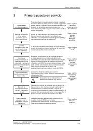
<strong>Operator</strong> Panel Front OP 03011.1 Function blocks of operator panel frontAluminum front panel with membrane keyboardMonochrome LCD module 240x128 pixels capable of text and graphics displaywith integrated controller and CCFL backlightFive horizontal soft keysCursor key groupNumerical key group with override and input keyPower supply24VDC input© Siemens AG, 2002. All rights reserved<strong>SINUMERIK</strong> <strong>840D</strong>/<strong>840D</strong>i/<strong>810D</strong> <strong>Operator</strong> <strong>Components</strong> Manual (BH) – 11.02 Edition1-21
1 <strong>Operator</strong> Panel Front OP 0301.2 Control elements and interfaces10.001.2 Control elements and interfacesPosition of controlelementsSIEMENS<strong>SINUMERIK</strong>7 8 94 5 61 2 30Numerical keygroup withoverride andinput keySoft keys (horizontal)Cursor keygroupFig. 1-1Front view of operator panel frontX101X201SIEMENSX301123Fig. 1-2Rear viewOverview ofinterfacesX101: Serial RS-232-CX201: OPI (operator panel front interface)X301: 24V power supply1-22© Siemens AG, 2002. All rights reserved<strong>SINUMERIK</strong> <strong>840D</strong>/<strong>840D</strong>i/<strong>810D</strong> <strong>Operator</strong> <strong>Components</strong> Manual (BH) – 11.02 Edition
10.001 <strong>Operator</strong> Panel Front OP 0301.2 Control elements and interfacesSerial RS-232-CConnector designation:Connector type:Max. cable length:X101Sub-D, 9-pin, straight30mTable 1-2X101 pin assignments for serial RS-232-CX303Pin Name Type1 DCD O2 RxD I3 TxD O4 DTR I5 M VO6 DSR O7 RTS I8 CTS O9 RI IJumpers closedPins 1 – 4 – 6Pins 7 – 8Signal namesTxDRxDCTSRTSDTRDSRRIDCDMSignal typeIOVOInputOutputVoltage OutputTransmit Data RS232CReceive Data RS232CClear To SendRequest To SendData Terminal ReadyData Send ReadyRing IndicatorData Carrier DetectGround© Siemens AG, 2002. All rights reserved<strong>SINUMERIK</strong> <strong>840D</strong>/<strong>840D</strong>i/<strong>810D</strong> <strong>Operator</strong> <strong>Components</strong> Manual (BH) – 11.02 Edition1-23
1 <strong>Operator</strong> Panel Front OP 0301.2 Control elements and interfaces10.00OPI(operator panelfront interface)Connector designation:Connector type:Max. cable length:X201Sub D-female, 9-pin, straight200mTable 1-3X201 pin assignments for OPI(operator panel front interface)X201Pin Name Type123 RS_OPI B4 ORTSAS_OPI O5 MEXT VO6 P5EXT VO78 XRS_OPI B9 IRTSPG_OPI ISignal namesRS_OPIXRS_OPIIRTSPG_OPIORTSAS_OPIMEXTP5EXTSignal typeIOBVOInputOutputBidirectionalVoltage Output<strong>Operator</strong> panel interface cable A<strong>Operator</strong> panel interface cable BInput Request To Send, programmingdeviceOutput Request To Send, interface moduleExternal ground5V external, isolated1-24© Siemens AG, 2002. All rights reserved<strong>SINUMERIK</strong> <strong>840D</strong>/<strong>840D</strong>i/<strong>810D</strong> <strong>Operator</strong> <strong>Components</strong> Manual (BH) – 11.02 Edition
10.001 <strong>Operator</strong> Panel Front OP 0301.2 Control elements and interfaces24V power supplyConnector designation:Connector type:X301Phoenix terminal block, 3-pin, right-angleTable 1-4X301 pin assignments for the 24V powersupplyX301Pin Name Type1 P24 VI2 M24 VI3 ShieldSignal namesP24M24ShieldSignal typeVI+24VDC supply voltageGroundEarth potentialVoltage Input© Siemens AG, 2002. All rights reserved<strong>SINUMERIK</strong> <strong>840D</strong>/<strong>840D</strong>i/<strong>810D</strong> <strong>Operator</strong> <strong>Components</strong> Manual (BH) – 11.02 Edition1-25
1 <strong>Operator</strong> Panel Front OP 0301.3 Dimension drawings and mounting instructions10.001.3 Dimension drawings and mounting instructionsDimensiondrawingsSIEMENS280<strong>SINUMERIK</strong>7 8 94 5 6–+1 2 30.182Fig. 1-3Front view262.4 0.1 8.882.2 0.1164.4 0.1 123SIEMENS131.2 0.18.8Fig. 1-4Rear view1-26© Siemens AG, 2002. All rights reserved<strong>SINUMERIK</strong> <strong>840D</strong>/<strong>840D</strong>i/<strong>810D</strong> <strong>Operator</strong> <strong>Components</strong> Manual (BH) – 11.02 Edition
10.001 <strong>Operator</strong> Panel Front OP 0301.3 Dimension drawings and mounting instructions604Required clearance40203Fig. 1-5Side view (left)Installing operatorpanel frontRequired clearance2802223447Fig. 1-6Plan view of housingMounting position max. 60 off vertical permissibleFrontFig. 1-7Mounting position© Siemens AG, 2002. All rights reserved<strong>SINUMERIK</strong> <strong>840D</strong>/<strong>840D</strong>i/<strong>810D</strong> <strong>Operator</strong> <strong>Components</strong> Manual (BH) – 11.02 Edition1-27
1 <strong>Operator</strong> Panel Front OP 0301.3 Dimension drawings and mounting instructions10.00Panel cutout0 8 –0.5131.2 0.1 254.4 0.5 262.4 0.1164.4 0.1156.4 0.582.2 0.18 –0.501.51.0/1005 +0.5Fig. 1-8Cutout for operator panel front (front view)Heat dissipationSee Chapter “Heat Dissipation”1-28© Siemens AG, 2002. All rights reserved<strong>SINUMERIK</strong> <strong>840D</strong>/<strong>840D</strong>i/<strong>810D</strong> <strong>Operator</strong> <strong>Components</strong> Manual (BH) – 11.02 Edition
10.001 <strong>Operator</strong> Panel Front OP 0301.4 Technical data1.4 Technical dataTable 1-5Technical data for operator panel frontElectrical data (operation with open interfaces)Total current +24VTypicalMaximumMechanical data200mA260mADimensions Width Height DepthBasic color of casing280mm 182mm 47mmAnthracite, acc. to SN 47030, Part 2, Color code:614Environmental conditionsTemperature ranges Installed/in operation Storage/transportLimit values 0...40°C –20 ... 60°CService life 10,000h at 25°C© Siemens AG, 2002. All rights reserved<strong>SINUMERIK</strong> <strong>840D</strong>/<strong>840D</strong>i/<strong>810D</strong> <strong>Operator</strong> <strong>Components</strong> Manual (BH) – 11.02 Edition1-29
1 <strong>Operator</strong> Panel Front OP 0301.4 Technical data10.00Notes1-30© Siemens AG, 2002. All rights reserved<strong>SINUMERIK</strong> <strong>840D</strong>/<strong>840D</strong>i/<strong>810D</strong> <strong>Operator</strong> <strong>Components</strong> Manual (BH) – 11.02 Edition
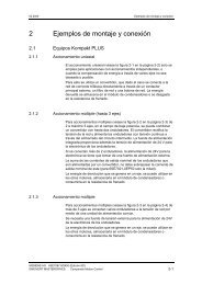
Flat Slimline <strong>Operator</strong> Panel FrontOP 032S22.1 Overview of componentsNoteThe slimline operator panel front OP 032S (OP 032 Small) and its componentscan be used in conjunction with the following control systems:– <strong>SINUMERIK</strong> <strong>840D</strong>– <strong>SINUMERIK</strong> <strong>810D</strong>.<strong>Operator</strong>componentsThe operator panel front OP 032S consists of the following components: Slimline operator panel front OP 032S CNC keyboard (QWERTY) OP 032S Machine control panel (MCP) OP 032S.31080 1)24330Slimline operatorpanel frontOP 032SPowersupplyMMC-CPU3)680175CNC keyboard(QWERTY)OP 032SISA/PCIadapter4)175Machine controlpanel(MCP)OP 032S2)1) A clearance (approx. 30mm) should be provided.2) The rear side is determined by the optional control elements.3) Is required for operating the slimline operator panel front.4) Can be installed as an optionFig. 2-1Overview of operator components© Siemens AG, 2002. All rights reserved<strong>SINUMERIK</strong> <strong>840D</strong>/<strong>840D</strong>i/<strong>810D</strong> <strong>Operator</strong> <strong>Components</strong> Manual (BH) – 11.02 Edition2-31
2 Flat Slimline <strong>Operator</strong> Panel Front OP 032S2.1 Overview of components10.00Overview ofconnectionsPowersupply24 V0 VPEMMCCPUNCU/CCUX10/MF2X4/MPIMPI cableOPI (1.5 Mbaud)/MPI (187.5 kbaud)24 V0 VPEX10X20Fig. 2-2Overview of connectionsFor furtherinformationon configuring, please refer to:References: /PHD/ <strong>SINUMERIK</strong> <strong>840D</strong>,NCU 571–573 ManualReferences: /PHG/ <strong>SINUMERIK</strong> <strong>810D</strong>,Configuring ManualHeat dissipationSee Chapter “Heat Dissipation”.2-32© Siemens AG, 2002. All rights reserved<strong>SINUMERIK</strong> <strong>840D</strong>/<strong>840D</strong>i/<strong>810D</strong> <strong>Operator</strong> <strong>Components</strong> Manual (BH) – 11.02 Edition
10.002 Flat Slimline <strong>Operator</strong> Panel Front OP 032S2.1 Overview of components2.1.1 US layout>>MACHINEMENUSELECTFig. 2-3<strong>Operator</strong> panel front with US layout© Siemens AG, 2002. All rights reserved<strong>SINUMERIK</strong> <strong>840D</strong>/<strong>840D</strong>i/<strong>810D</strong> <strong>Operator</strong> <strong>Components</strong> Manual (BH) – 11.02 Edition2-33
2 Flat Slimline <strong>Operator</strong> Panel Front OP 032S2.1 Overview of components10.00Q W E R T Y U I O P? & (/ 7 8 9A S D F G H J K L”,*$%4 5 6Z X C V B N M= [ ]––!@ #1 2 3CtrlAlt|< :\ . ; [TAB+)+/– 0>←ALARMRESETHELPAlarmGROUPCHANNELNEXTWINDOWPAGEUP←SELECT→DELSHIFTPROGRAMTOOLOFFSETEndPAGEDOWN←BACKSPACEInsertInputFig. 2-4CNC keyboard with US layoutNoteThe five additional keys (Help, Alarm, Program, Tool Offset, Space key) are notsupported by the standard block DB 19 of the PLC basic program. The userprogram must be adapted accordingly for this purpose.2-34© Siemens AG, 2002. All rights reserved<strong>SINUMERIK</strong> <strong>840D</strong>/<strong>840D</strong>i/<strong>810D</strong> <strong>Operator</strong> <strong>Components</strong> Manual (BH) – 11.02 Edition
10.002 Flat Slimline <strong>Operator</strong> Panel Front OP 032S2.1 Overview of componentsJOGREPOSREFPOINT→[VAR]SPINDLEDEC.100%SPINDLEINC.MDITEACHIN→1SPINDLERIGHTSPINDLESTOPSPINDLELEFTAUTO→10XYZSINGLEBLOCKRESET→1004 5 6STOPSTART→1000WCSMCSFEEDSTOPFEEDSTART–RAPID+Fig. 2-5MCP with US layout© Siemens AG, 2002. All rights reserved<strong>SINUMERIK</strong> <strong>840D</strong>/<strong>840D</strong>i/<strong>810D</strong> <strong>Operator</strong> <strong>Components</strong> Manual (BH) – 11.02 Edition2-35
2 Flat Slimline <strong>Operator</strong> Panel Front OP 032S2.2 Flat operator panel front OP 032S10.002.2 Flat operator panel front OP 032S2.2.1 Function blocks of operator panel frontSoft keys (eight vertical, eight horizontal)Screen control keys (four pcs.)Screen– Display design:TFT flat color screen, 10.4 inch, resolution 640x48024V power supply– 24VDC input– Power supply interface for MMC unit and displayMounting– W x H x D: 310x330x68mmAdd-oncomponents MMC CPUs (MMC 100, 100.2, 102, 103)NoteFor MMC 100 and 102, the following ribbon cable is required for connectionbetween MMC and power supply:Ribbon cable for power supplyfor MMC 100 / MMC 102 Order No. 6FC5 247-0AB28-0AA02-36© Siemens AG, 2002. All rights reserved<strong>SINUMERIK</strong> <strong>840D</strong>/<strong>840D</strong>i/<strong>810D</strong> <strong>Operator</strong> <strong>Components</strong> Manual (BH) – 11.02 Edition
10.002 Flat Slimline <strong>Operator</strong> Panel Front OP 032S2.2 Flat operator panel front OP 032S2.2.2 Control elements and interfacesPosition of controlelementsSoft key bar(vertical)DisplaySoft key bar(horizontal)Screencontrol keysFig. 2-6Front view of flat operator panel frontPower supplyPE0V24VX3 X4EquipotentialbondingX51MMCHarddiskdriveX6X10S1 X11S21Fig. 2-7Rear view of flat operator panel front© Siemens AG, 2002. All rights reserved<strong>SINUMERIK</strong> <strong>840D</strong>/<strong>840D</strong>i/<strong>810D</strong> <strong>Operator</strong> <strong>Components</strong> Manual (BH) – 11.02 Edition2-37
2 Flat Slimline <strong>Operator</strong> Panel Front OP 032S2.2 Flat operator panel front OP 032S10.00Installing MMCmodule MMC 100,MMC 101/1021. Put the flat operator panel front on an appropriate surface as shown inFig. 2-7 (power supply module is on top).2. Loosen the four Torx screws (M4) for attaching the MMC.3. Suspend the MMC module from the four screws such that interfaces X4, X5and X6 are facing to the right.4. Push the complete module unit down until the bus connector snaps intoplace.5. Attach the MMC module by tightening the four Torx screws (max. tighteningtorque 1.5Nm).6. Connect the power supply to the MMC module using the ribbon cable.Installing the MMCmodule MMC 1031. Put the slimline operator panel front on an appropriate surface as shown inFig. 2-7 (flat power supply module is on top).2. Loosen the four Torx screws (M4) for the power supply module and push thepower supply module completely to the top.3. Loosen the four Torx screws (M4) for attaching the MMC.4. Suspend the MMC module from the 4 screws such that interfaces X4, X5and X6 are facing to the right.5. Push the complete module unit down until the bus connector snaps intoplace.6. Attach the MMC module by tightening the four Torx screws (max. tighteningtorque 1.5Nm).7. Push the power supply module down until the power supply connectorsnaps into place.8. Fix the MMC module by tightening the four Torx screws (max. tighteningtorque 1.5Nm).Power supplyinterface (X1)Connector designation:Connector type:X1MSTB 2.5/3–G–5.08; 3-pinTable 2-1X1 pin assignmentsPin Signal, name Signal type1 P24, 24V potential V, supply voltage2 M24, 24V ground V, supply voltage3 SHIELD, shield connection V, supply voltage2-38© Siemens AG, 2002. All rights reserved<strong>SINUMERIK</strong> <strong>840D</strong>/<strong>840D</strong>i/<strong>810D</strong> <strong>Operator</strong> <strong>Components</strong> Manual (BH) – 11.02 Edition
10.002 Flat Slimline <strong>Operator</strong> Panel Front OP 032S2.2 Flat operator panel front OP 032S2.2.3 Mounting instructions, dimension drawing and panel cutout304)3)2)301)2)301)5)30301) Necessary clearance2) Measured from the upper edge of the MMC used3) Permitted mounting position max. 60 degrees to the perpendicular4) Recommended screw M4 with washer DIN 1255) M5 grounding connectorFig. 2-8Mounting instructions for flat operator panel front© Siemens AG, 2002. All rights reserved<strong>SINUMERIK</strong> <strong>840D</strong>/<strong>840D</strong>i/<strong>810D</strong> <strong>Operator</strong> <strong>Components</strong> Manual (BH) – 11.02 Edition2-39
2 Flat Slimline <strong>Operator</strong> Panel Front OP 032S2.2 Flat operator panel front OP 032S10.00330321302.55.5309.40 13.8 154.7 295.652479.153.1 241)732)5527.59019.719.7151) Minimum mounting depth forMMC 1032) Minimum mounting depth forMMC 100.2Fig. 2-9Dimension drawing for flat operator panel front2-40© Siemens AG, 2002. All rights reserved<strong>SINUMERIK</strong> <strong>840D</strong>/<strong>840D</strong>i/<strong>810D</strong> <strong>Operator</strong> <strong>Components</strong> Manual (BH) – 11.02 Edition
10.002 Flat Slimline <strong>Operator</strong> Panel Front OP 032S2.2 Flat operator panel front OP 032S4.4 0136.5273277.43073022802)2) 2)Front panel cutout for flat7+ 0.5(4 times)2)0.522052)operator panel front 3) 15.8 0.5 1)2)2)2)Front panel cutoutfor CNC keyboard 3)1) Necessary mounting clearance for using an ISA or ISA/PCI adapter2) Rivet-down, insert nut M4 or extruded hole M43) Front panel cutouts for installation from the rear:<strong>Operator</strong> panel front: W x H = 301.4x278mmKeyboard:W x H = 301.4x153mmFig. 2-10Panel cutout for flat operator panel front (rear view)© Siemens AG, 2002. All rights reserved<strong>SINUMERIK</strong> <strong>840D</strong>/<strong>840D</strong>i/<strong>810D</strong> <strong>Operator</strong> <strong>Components</strong> Manual (BH) – 11.02 Edition2-41
ÉÉÉÉÉÉÉÉ2 Flat Slimline <strong>Operator</strong> Panel Front OP 032S2.2 Flat operator panel front OP 032S10.002.2.4 Using an ISA/PCI adapterArrangements foruse of an ISA/PCIadapterIf an ISA/PCI adapter is used, the following arrangements are possible: Vertical, flat arrangement Desk-type arrangement.Vertical,flat arrangementDesk-type arrangementPowersupplyMMCCPUFlatoperatorpanelfrontFlatoperatorpanelfrontÉÉSame mountingsurfaceAuxiliarymounting plate(thickness =2mm)ISA/PCIadapterÉÉCNCkeyboardÉÉÉÉÉCNCkeyboardNote:The ISA/PCI adapter is mounted onthe rear panel of the CNC keyboard.ÉNote:The ISA/PCI adapter is mountedon an auxiliary mounting plate.ÉFig. 2-11Arrangement when using an ISA/PCI adapter2-42© Siemens AG, 2002. All rights reserved<strong>SINUMERIK</strong> <strong>840D</strong>/<strong>840D</strong>i/<strong>810D</strong> <strong>Operator</strong> <strong>Components</strong> Manual (BH) – 11.02 Edition
10.002 Flat Slimline <strong>Operator</strong> Panel Front OP 032S2.2 Flat operator panel front OP 032SRear view whenusing anISA/PCI adapterPowersupplyMMCCPUSlimlineoperatorpanel frontISA/PCIadapterCNCkeyboard40–50mm clearance forconnector of ISA/PCI plug-in cardsFig. 2-12Rear view when using an ISA/PCI adapter© Siemens AG, 2002. All rights reserved<strong>SINUMERIK</strong> <strong>840D</strong>/<strong>840D</strong>i/<strong>810D</strong> <strong>Operator</strong> <strong>Components</strong> Manual (BH) – 11.02 Edition2-43
2 Flat Slimline <strong>Operator</strong> Panel Front OP 032S2.2 Flat operator panel front OP 032S10.00Mounting theISA/PCI adapter onthe rear panel ofthe CNC keyboardMounting the adapter on the rear panel of the CNC keyboard is only possible fora vertical, flat arrangement.Sequence for mounting:1. Fasten the two brackets on the adapter (1) as shown in Fig. 2-13.2. Loosen both screws (2) on the rear of the keyboard.3. Position the adapter on the rear panel of the CNC keyboard.4. Push the adapter in the direction of the slimline operator panel front until theinterface snaps into place on the top right-hand side.5. Tighten the screws on the bottom of the adapter (2).41122Fig. 2-13Mounting ISA/PCI adapter on rear panel of CNC keyboard2-44© Siemens AG, 2002. All rights reserved<strong>SINUMERIK</strong> <strong>840D</strong>/<strong>840D</strong>i/<strong>810D</strong> <strong>Operator</strong> <strong>Components</strong> Manual (BH) – 11.02 Edition
10.002 Flat Slimline <strong>Operator</strong> Panel Front OP 032S2.2 Flat operator panel front OP 032SMounting theISA/PCI adapter onthe auxiliarymounting platewith precutelongated holesWhen mounting the adapter on the desk-type arrangement, an auxiliary mountingplate is needed.The mounting procedure is the same as on the rear panel of the CNC keyboard.Outline of flat operator panel front042.81)Front panel cutoutfor flat operator panel front(display module)Plate thickness = 2 mm1)113.81411)2) 2)1)Outline(175 x 299.4, asCNC keyboard)111.9 101.41) Cutout for support(see detail Y)2) M4 for mounting the supports(rivet-down nut)Tolerance for dimensions: 0.5Note: The fastening holes for the auxiliary mountingplate are not shown in this drawing.0 103.1 113.6Detail Y1.3 x 45° 6.51227.3Fig. 2-14Hole pattern and dimensions for the auxiliary mounting plate (rear view)Sequence for mounting:1. Make the cutouts and holes for fastening the adapter (see Fig. 2-14).2. Fasten the two brackets to the adapter using the provided screws (flangeinside).3. Position the adapter on the auxiliary mounting plate.4. Push the adapter in the direction of the slimline operator panel front until theinterface snaps into place.5. Tighten the screws on the bottom of the adapter.© Siemens AG, 2002. All rights reserved<strong>SINUMERIK</strong> <strong>840D</strong>/<strong>840D</strong>i/<strong>810D</strong> <strong>Operator</strong> <strong>Components</strong> Manual (BH) – 11.02 Edition2-45
2 Flat Slimline <strong>Operator</strong> Panel Front OP 032S2.2 Flat operator panel front OP 032S10.00Mounting theISA/PCI adapter onthe auxiliarymounting platewith precutelongated holesWhen mounting the adapter on the desk-type arrangement, an auxiliary mountingplate is needed.Outline of flat operator panel front033.635.61)Front panel cutoutfor flat operator panel front(display module)1)75.6107.11)Plate thickness = 2mmMounting bracketsrequired(not supplied bySiemens)1)Outline(175x299.4, asCNC keyboard)127 0125.51) M4 for mounting the supports(rivet-down nut)Tolerance for dimensions: 0.5Note: The fastening holes for the auxiliarymounting plate are not shown inthis drawing.Mounting bracket– Not to dimension)– Plate thickness = 1mm1120Rivet nut M41540507Hole 4.5Fig. 2-15Hole pattern and dimensions for the auxiliary mounting plate (rear view)Sequence for mounting:1. Make the cutouts and holes for fastening the adapter and the mountingbracket (see Fig. 2-15).2. Fasten the two brackets on the right to the adapter using the providedscrews (flange outside).3. Position the adapter on the auxiliary mounting plate.4. Push the adapter in the direction of the slimline operator panel front until theinterface snaps into place.5. Tighten the screws on the right and left-hand sides of the adapter.2-46© Siemens AG, 2002. All rights reserved<strong>SINUMERIK</strong> <strong>840D</strong>/<strong>840D</strong>i/<strong>810D</strong> <strong>Operator</strong> <strong>Components</strong> Manual (BH) – 11.02 Edition
10.002 Flat Slimline <strong>Operator</strong> Panel Front OP 032S2.2 Flat operator panel front OP 032S2.2.5 Technical data for flat operator panel frontTable 2-2Technical data for flat operator panel frontElectrical data (data with open interfaces)Total current +24VTypical (without MMC) 0.3AMax.Power loss max.Mechanical data7.5A (for full expansion)180WDimensions Width Height DepthGround309.4mm 330mm 26mmApprox. 3.88kgBasic color of casing Anthracite, acc. to SN 47030, Part 2, Color code: 614Environmental conditionsTemperature rangesLimit values for use/operation:Rear 0 ... 55°CFront 0 ... 45°CLimit values for storage: –20 ... 60°CTemperature variation within 1 minute max. 0.2KService life Color display (without backlight) min. 20,000hPermissible change in relative humidity EN 60721-3-3, Class 3K5Intake airwithin 1 minute max. 0.1%Degree of protection to DIN40050without aggressive gasesFront IP 54, rear IP 20NoteThe backlights should be switched off with a screen saver, when the lamp remainsoff for more than 1 hour on an average.The component with the smallest temperature range in the whole configurationdetermines the temperature range of the whole system.For the technical data of the MMC component used, please refer to the relevantsection “Technical data of MMCxxx”.© Siemens AG, 2002. All rights reserved<strong>SINUMERIK</strong> <strong>840D</strong>/<strong>840D</strong>i/<strong>810D</strong> <strong>Operator</strong> <strong>Components</strong> Manual (BH) – 11.02 Edition2-47
2 Flat Slimline <strong>Operator</strong> Panel Front OP 032S2.3 CNC keyboard OP 032S10.002.3 CNC keyboard OP 032S2.3.1 Function blocks74 keysLayout similar to standard MFII keyboardLayout variants QWERTY and DIN available.Fig. 2-16Front view of CNC keyboard OP 032S2.3.2 Connection of CNC keyboardKeyboard interfaceto MMC(X111)Connector designation:X111Connector type:Mini DIN connector, 6-pin, straightCable length to MMC-CPU: max. 0.5mCNC keyboardMMC-CPUX111MFII interfaceX10Fig. 2-17Connection of CNC keyboard2-48© Siemens AG, 2002. All rights reserved<strong>SINUMERIK</strong> <strong>840D</strong>/<strong>840D</strong>i/<strong>810D</strong> <strong>Operator</strong> <strong>Components</strong> Manual (BH) – 11.02 Edition
10.002 Flat Slimline <strong>Operator</strong> Panel Front OP 032S2.3 CNC keyboard OP 032S2.3.3 Mounting instructions, dimension drawing and panel cutoutWith ISA/PCI adapter2)3060°4)1)5)1.8Nm1)3030 – 50 6) 301)2)303)301) Necessary clearance2) Measured from the upper edge of the ISA/PCI adapter3) M5 grounding connector4) Permitted mounting position max. 60° to theperpendicular5) Recommended screw M4 with washer DIN 125Torque 1.8 Nm.6) Required clearance for connector on ISA/PCI card(depending on the connectors used)Fig. 2-18Mounting instructions for CNC keyboard© Siemens AG, 2002. All rights reserved<strong>SINUMERIK</strong> <strong>840D</strong>/<strong>840D</strong>i/<strong>810D</strong> <strong>Operator</strong> <strong>Components</strong> Manual (BH) – 11.02 Edition2-49
2 Flat Slimline <strong>Operator</strong> Panel Front OP 032S2.3 CNC keyboard OP 032S10.0013.80154.71)309.4295.6103175169162.51)144.412.56053.424.8 19.677241)1) Dimensions of theISA/PCI adapterFig. 2-19Dimension drawing of CNC keyboardM4 (6 times) 1)158153145.57 (4 times)0.57.505.6.74.4136.5 273 279.7277.41) Rivet-down, insert nut M4orextruded hole M4Front panel cutout for installation from the rear: WxH = 301.4x153mmFig. 2-20Panel cutout for CNC keyboard (rear view)2-50© Siemens AG, 2002. All rights reserved<strong>SINUMERIK</strong> <strong>840D</strong>/<strong>840D</strong>i/<strong>810D</strong> <strong>Operator</strong> <strong>Components</strong> Manual (BH) – 11.02 Edition
10.002 Flat Slimline <strong>Operator</strong> Panel Front OP 032S2.3 CNC keyboard OP 032S2.3.4 Technical data for CNC keyboardTable 2-3Technical data for CNC keyboard OP 032SElectrical dataVoltage max. 5.25VCurrent, typical18mAPower loss max. 0.1WMechanical dataDimensions Width Height Depth309.4mm 175mm 26mmGroundApprox. 1.35 kgEnvironmental conditionsTemperature rangesLimit values for use/operation:Rear 0 ... 55°CFront 0 ... 45°CLimit values for storage: –20 ... 60°CTemperature variation within 1 minute max. 0.2KPermissible change in relative humidity EN 60721-3-3, Class 3K5Intake airwithin 1 minute max. 0.1%Degree of protection to DIN40050without aggressive gasesFront IP 54, rear IP 00© Siemens AG, 2002. All rights reserved<strong>SINUMERIK</strong> <strong>840D</strong>/<strong>840D</strong>i/<strong>810D</strong> <strong>Operator</strong> <strong>Components</strong> Manual (BH) – 11.02 Edition2-51
2 Flat Slimline <strong>Operator</strong> Panel Front OP 032S2.4 Machine control panel OP 032S10.002.4 Machine control panel OP 032S2.4.1 Function blocks of machine control panelKey caps (49 pcs., 48 with LED, can all be assembled variably)Feedrate override switchPossibility of installing optional customer-specific keys,EMERGENCY STOP or second override switchTen free inputs 24Vsix free 24V/250 mA outputs.2.4.2 Control elements and interfacesKey 1LED 1Key 10LED 10Recess fordial (EMER-GENCYSTOP, overrideswitch)Key 11LED 11Key 41LED 41Supplementarycontrol elements(EMER-GENCYSTOP oroverrideswitch)FeedrateoverrideswitchSupplementary control elements(6 keys, 1 keyswitch)Key 50LED 50Fig. 2-21Front view of machine control panel, overview and location of control elementsControl elementswhen suppliedWhen supplied, the following control elements are provided on the machinecontrol panel:Key caps (49 pcs., 48 with LED, can all be assembled variably)Feed override switch.2-52© Siemens AG, 2002. All rights reserved<strong>SINUMERIK</strong> <strong>840D</strong>/<strong>840D</strong>i/<strong>810D</strong> <strong>Operator</strong> <strong>Components</strong> Manual (BH) – 11.02 Edition
10.002 Flat Slimline <strong>Operator</strong> Panel Front OP 032S2.4 Machine control panel OP 032SMaking theopenings with adrilling toolThe openings for the supplementary control elements are embossed on the rearside of the machine control panel.The diameter for the horizontal cutouts is 16.2 to 16.4mm.The diameter for the EMERGENCY STOP button is 22.2 to 22.4mm.Recommended: Drill the openings from the rear as follows:Clamp the machine control panel for machining on the rear (use suitabledrilling support).Switch the chip extractor on or cover the electrical parts to prevent chipsfrom falling on them.NoteBefore drilling the opening, metal chips must be removed from the drills.Use the appropriate drill to drill the desired openings (openings are centered).Making the cutoutsby knocking outThe cutouts should be knocked out only if the control elements used cover thebroken edges on the front panel (no sharp broken edges).Supplementarycontrol elementsThe following control elements can be added:EMERGENCY STOP– <strong>Operator</strong> control element: SIEMENS 3SB3000-1HA20– Switching element 3SB3400-0A (1 NO contact + 1 NC contact)Additional override switchOverride switch with wing cap, spacer, cover, 2 dials.– CBS 1/1x1GG (16/15°) switch– Spindle override 50–120% dial– Rapid traverse override 0–100% dial.The second override switch must be connected via X31–X32.Order No. 6FC5 247-0AA34-0AA1.© Siemens AG, 2002. All rights reserved<strong>SINUMERIK</strong> <strong>840D</strong>/<strong>840D</strong>i/<strong>810D</strong> <strong>Operator</strong> <strong>Components</strong> Manual (BH) – 11.02 Edition2-53
2 Flat Slimline <strong>Operator</strong> Panel Front OP 032S2.4 Machine control panel OP 032S10.00Table 2-4Example showing connection of additional override switchPin Meaning: Switch wiringX31 pin 4Ground = CX32 pin 2 Significance 2 2 = 4CNC N.C.4N.C.X32 pin 1 Significance 2 4 = 16 16N.C.8X31 pin 3 Significance 2 3 = 8N.C.2N.C.X31 pin 2 Significance 2 1 = 2 1X31 pin 1 Significance 2 0 = 1 Base ofoverride switchCable set for additional command devices for interfaces X31–X36A maximum of six cables are required for each MCP.60 cables x 500 mmOrder No. 6FC5 247-0AA35-0AA0Six keys with lamps + one keyswitchThe keys and the keyswitch are connected to X31–X34 (input signals).The lamps are connected to X35 and X36 (output signals).Recommended type for keys and keyswitch:Rafix 16, Lumotast 25, Schlegel QUARTRONSource:Schlegel (http://schlegel-ekontakt.de),RAFI (http://www.rafi.de)2-54© Siemens AG, 2002. All rights reserved<strong>SINUMERIK</strong> <strong>840D</strong>/<strong>840D</strong>i/<strong>810D</strong> <strong>Operator</strong> <strong>Components</strong> Manual (BH) – 11.02 Edition
10.002 Flat Slimline <strong>Operator</strong> Panel Front OP 032S2.4 Machine control panel OP 032S1)22.4X20130.7125.63)DIP switch8 112344)Plug connector1x6 pin 3)5740X1024/0V2956.534.50259.98228.92 177.8233 208.15147.45117.116.386.7556.426.0510.402)01) Location intended for EMERGENCY STOP or second override switch (22mm)Prepared for 22mm emergency stop mounting geometryRecommended design:Recommended design:2) Location for 7 control devices (16mm)SIEMENS 3SB3000-1HA20Contact 3SB3400-0A 1S + 1OModule variants:3) 571241.9001.004) 571241.9001.01Fig. 2-22Rear view of the machine control panel, dimensions of the machine control panelX20<strong>Operator</strong> panel frontinterface (MPI)OutputsDIP switch8 1O S3N LED: 1234Plug connector1x6 pinX10Pin 4 1 4 1 Pin 4 1 4 1DIP switch (8-fold),assignmentsInputsPower supplyinterfaceProtective earthDisplays: LED 1, 2: UnassignedLED 3: POWER (24V supply)LED 4: SEND, status change when sending protocolFor module variants see Fig. 2-22Fig. 2-23Rear view of the machine control panel, overview and location of interfaces© Siemens AG, 2002. All rights reserved<strong>SINUMERIK</strong> <strong>840D</strong>/<strong>840D</strong>i/<strong>810D</strong> <strong>Operator</strong> <strong>Components</strong> Manual (BH) – 11.02 Edition2-55
2 Flat Slimline <strong>Operator</strong> Panel Front OP 032S2.4 Machine control panel OP 032S10.00Power supplyinterface(X10)Connector designation:Connector type:Recommended type:X103-pin Phoenix terminal block, straightPhoenix CombiConOrder No.: MVSTBR 2.5/3-ST-5.08Table 2-5X10 pin assignmentsPin Signal, name Signal type1 P24, 24V potential V, supply voltage2 M24, 24V ground V, supply voltage3 SHIELD, shield connection V, supply voltageNoteThe power supply interface should be wired in accordance with the labeling onthe module.OPI interface(X20)Connector designation:Connector type:Maximum cable length:Special features:X209-pin Sub-D socket connector, straight200m1.5 Mbaud/187.5 kbaud data rateTable 2-6X20 pin assignmentsPin Signal, name Signal type1 Unassigned –2 Unassigned –3 RS_OPI, RS-485 data I/O, bidirectional4 ORTSAS_OPI, Out Request To Send AS O, output5 M5EXT, 5V ground, external V, supply voltage6 P5EXT, 5V potential, external V, supply voltage7 Unassigned –8 XRS_OPI, RS485 data I/O, bidirectional9 IRTSPG_OPI, In Request To Send PG I/O, bidirectionalNoteThe inputs/outputs implemented via X31 to X36 can be used as desired. Thefunction of the inputs/outputs is defined in the PLC user program.The following inputs/outputs via X31 to X36 and their use are examples.2-56© Siemens AG, 2002. All rights reserved<strong>SINUMERIK</strong> <strong>840D</strong>/<strong>840D</strong>i/<strong>810D</strong> <strong>Operator</strong> <strong>Components</strong> Manual (BH) – 11.02 Edition
10.002 Flat Slimline <strong>Operator</strong> Panel Front OP 032S2.4 Machine control panel OP 032SAssignmentsThe following settings are possible with this DIP switch (8-fold):Table 2-7Assignments with switch S31 2 3 4 5 6 7 8 Meaning:ONOFFONOFFOFFOFFONOFFONONONONONONONONOFFOFFOFFOFFOFFOFFOFFOFFONONONONOFFOFFOFFOFFONONONONOFFOFFOFFOFFONONOFFOFFONONOFFOFFONONOFFOFFONONOFFOFFONOFFONOFFONOFFONOFFONOFFONOFFONOFFONOFFONOFFBaud rate: 1.5 MbaudBaud rate: 187.5 kbaud200 msecs transmission cycle time/2400msecs receiptmonitoring100 msecs transmission cycle time/1200msecs receiptmonitoring50 msecs transmission cycle time/600msecs receipt monitoringBus address: 15Bus address: 14Bus address: 13Bus address: 12Bus address: 11Bus address: 10Bus address: 9Bus address: 8Bus address: 7Bus address: 6Bus address: 5Bus address: 4Bus address: 3Bus address: 2Bus address: 1Bus address: 0MPI interface, customer operator panel frontSerial hardwareSettings for thetransmissioncycle timeThe PLC expects a message frame from the MCP at least every 500 msecs.The machine control panel sends a message frame to the PLC at cyclic intervalswhen no key is pressed. This cycle time is set with S3 DIP switches 2 and3. This enables the load on the PLC resulting from the machine control panel tobe adjusted.Settings forreceipt cycle timeThe MCP receives message frames from the PLC at cyclic intervals and respondsto them at cyclic intervals. The receipt monitoring time is linked to thetransmission cycle time of the machine control panel and is set with S3 DIPswitches 2 and 3.Bus addressThe bus address must be set to the value 6. Any other setting will be ignored bythe software.Default settingThe following default settings are suggested:Table 2-8Default setting for S31 2 3 4 5 6 7 8 Meaning:ON OFF ON OFF ON ON OFF OFF Baud rate: 1.5 MbaudTransmission cycle time:100 msecsBus address: 6© Siemens AG, 2002. All rights reserved<strong>SINUMERIK</strong> <strong>840D</strong>/<strong>840D</strong>i/<strong>810D</strong> <strong>Operator</strong> <strong>Components</strong> Manual (BH) – 11.02 Edition2-57
2 Flat Slimline <strong>Operator</strong> Panel Front OP 032S2.4 Machine control panel OP 032S10.00Displays(LEDs 1 ... 4)These LEDs display the following:LED 1, LED 2: UnassignedLED 3: POWER (24V supply)LED 4: SEND, status change when sending protocolInterfaces foroptional user keys(X31, X32, inputs)Connector designation:Connector type:X31, X324-pin plug connectorConnector: Berg type DuboxTable 2-9X31 and X32 assignmentsPin Signal, name Signal typeX31X321 KT-IN 0, user key 1 KT-IN 3, user key 4 I, inputs2 KT-IN 1, user key 2 KT-IN 4, user key 5 I, inputs3 KT-IN 2, user key 3 KT-IN 5, user key 6 I, inputs4 M5, ground M5, ground I, inputsNote:The inputs switch against ground (active low).User key 1 (X31), 4 (X32)rd 1)User key 3 (X31), 6 (X32)GroundUser key 2 (X31), 5 (X32)View of pinside ofDubox connector to be plugged (socket connector)1) Color of line, red – pin 1 in cable setPinX311 2 3 4X321 2 3 4Plug connectorMachine control panel OP 032S (rear panel)2-58© Siemens AG, 2002. All rights reserved<strong>SINUMERIK</strong> <strong>840D</strong>/<strong>840D</strong>i/<strong>810D</strong> <strong>Operator</strong> <strong>Components</strong> Manual (BH) – 11.02 Edition
10.002 Flat Slimline <strong>Operator</strong> Panel Front OP 032S2.4 Machine control panel OP 032SInterfaces foroptional keyswitch(X33, X34, inputs)Connector designation:Connector type:X33, X344-pin plug connectorConnector: Berg type DuboxTable 2-10X33 and X34 assignmentsPin Signal, name Signal typeX33X341 SS 0,keyswitch input 02 SS 1,keyswitch input 1SS 2,keyswitch input 2SS 3,keyswitch input 3I, inputsI, inputs3 M5, ground M5, ground I, inputs4 M5, ground M5, ground I, inputsNote:The inputs switch against ground (active low).Other control elements can also be connected to these inputs.X33Position 1Position 4X34Pin 1Pin 1KeyswitchGroundInterfaces foroptional customerlamps(X35, X36, inputs)Connector designation:Connector type:Table 2-11X35 and X36 assignmentsX35, X364-pin plug connectorConnector: Berg type DuboxPin Signal, name Signal typeX35X361 KT-OUT 0, customer lamp 1 KT-OUT 3, customer lamp 4 O, outputs2 KT-OUT 1, customer lamp 2 KT-OUT 4, customer lamp 5 O, outputs3 KT-OUT 2, customer lamp 3 KT-OUT 5, customer lamp 6 O, outputs4 M24, 24V ground M24, 24 V ground O, outputsNote:The outputs are designed for 24 V/250 mA.Customer lamp 1 (X35), 4 (X36)Customer lamp 3 (X35), 6 (X36)Pin 124V groundCustomer lamp 2 (X35), 5 (X36)© Siemens AG, 2002. All rights reserved<strong>SINUMERIK</strong> <strong>840D</strong>/<strong>840D</strong>i/<strong>810D</strong> <strong>Operator</strong> <strong>Components</strong> Manual (BH) – 11.02 Edition2-59
2 Flat Slimline <strong>Operator</strong> Panel Front OP 032S2.4 Machine control panel OP 032S10.002.4.3 Dimension drawing and panel cutout5175 169162.5125.649.448.919.512.5601) Protective-conductor terminal M5, min. 6 mm 20 13.8 154.7 260 309.4295.61)30.511.52 2442.4Fig. 2-24Dimension drawing of machine control panel2-60© Siemens AG, 2002. All rights reserved<strong>SINUMERIK</strong> <strong>840D</strong>/<strong>840D</strong>i/<strong>810D</strong> <strong>Operator</strong> <strong>Components</strong> Manual (BH) – 11.02 Edition
10.002 Flat Slimline <strong>Operator</strong> Panel Front OP 032S2.4 Machine control panel OP 032SM4158153145.571)0.538056.7 010 4.4136.5 273 279.7277.41) DIN ISO 1101 Permissible mounting position of the operator panel plane max. 60°to the perpendicularFront panel cutouts for installation from the rear: W x H = 301.4x153mmInstallation from the rear is necessary, for example, when user keys are incorporated.Fig. 2-25Panel cutout of machine control panel© Siemens AG, 2002. All rights reserved<strong>SINUMERIK</strong> <strong>840D</strong>/<strong>840D</strong>i/<strong>810D</strong> <strong>Operator</strong> <strong>Components</strong> Manual (BH) – 11.02 Edition2-61
2 Flat Slimline <strong>Operator</strong> Panel Front OP 032S2.4 Machine control panel OP 032S10.002.4.4 Input and output signalsInput signalsThe control elements on the machine control panel are shown as input signals.The start address n is set in the PLC user program by parameterization.Input signals (MCP ––> PLC)Byte Bit 7 Bit 6 Bit 5 Bit 4 Bit 3 Bit 2 Bit 1 Bit 0n Key 41 *) Key 8 Key 9 Key 10 Key 31 Key 1 Key 11 Key 21n + 1 Key 43 Key 18 Key 19 *) Key 20 X34 pin 2 Key 3 Key 2 Key 12n + 2 Key 47 Key 46 *) Key 4 X33 pin 1 Key 44 Key 34 Key 24 Key 14n+3 Key 32 X34 pin 1 X33 pin 2Feed overrideE D C B An + 4 Key 50 Key 48 Key 49 X32 pin 2 X32 pin 1 X31 pin 3 X31 pin 2 X31 pin 1n + 5 Key 33 X32 pin 3 Key 40 Key 39 Key 38 Key 30 Key 29 Key 28n + 6 Key 27 Key 35 Key 36 Key 37 Key 45 Key 13 Key 22 Key 23n + 7 Key 5 Key 6 Key 7 Key 15 Key 16 Key 17 Key 25 Key 26NoteThe following generalrule applies:Exception:Key operated ––> input is highKey not operated ––> input is lowThe keys marked with *) respond in the opposite way.Output signalsThe LEDs and lamps on the machine control unit are actuated by means of thefollowing outputs.The initial address m is set in the PLC user program by parameterization.Output signals (PLC ––> MCP)Byte Bit 7 Bit 6 Bit 5 Bit 4 Bit 3 Bit 2 Bit 1 Bit 0n LED 41 LED 8 LED 9 LED 10 LED 31 LED 1 LED 11 LED 21m + 1 LED 43 LED 18 LED 19 LED 20 Reserved LED 3 LED 2 LED 12m + 2 LED 47 LED 46 LED 4 Reserved LED 44 LED 34 LED 24 LED 14m + 3Reservedm + 4 LED 50 LED 48 LED 49 X36 pin 2 X36 pin 1 X35 pin 3 X35 pin 2 X35 pin 1m + 5 LED 33 X36 pin 3 LED 40 LED 39 LED 38 LED 30 LED 29 LED 28m + 6 LED 27 LED 35 LED 36 LED 37 LED 45 LED 13 LED 22 LED 23m + 7 LED 5 LED 6 LED 7 LED 15 LED 16 LED 17 LED 25 LED 262-62© Siemens AG, 2002. All rights reserved<strong>SINUMERIK</strong> <strong>840D</strong>/<strong>840D</strong>i/<strong>810D</strong> <strong>Operator</strong> <strong>Components</strong> Manual (BH) – 11.02 Edition
10.002 Flat Slimline <strong>Operator</strong> Panel Front OP 032S2.4 Machine control panel OP 032SProgrammingFor programming of individual keys and LEDs, we recommend the followingoverview:IOn.2m.2n+1.1m+1.1n+1.2m+1.2n+2.5m+2.5n+7.7m+7.7n+7.6m+7.6n+7.5m+7.5n.6m.6n.5m.5n.4m.4IOn+0.1m+0.1n+1.0m+1.0n+6.2m+6.2n+2.0m+2.0n+7.4m+7.4n+7.3m+7.3n+7.2m+7.2n+1.6m+1.6n+1.5m+1.5n+1.4m+1.4IOn.0m.0n+6.1m+6.1n+6.0m+6.0n+2.1m+2.1n+7.1m+7.1n+7.0m+7.0n+6.7m+6.7n+5.0m+5.0n+5.1m+5.1n+5.2m+5.2IOn.3m.3n+3.7n+5.7m+5.7n+2.2m+2.2n+6.6m+6.6n+6.5m+6.5n+6.4m+6.4n+5.3m+5.3n+5.4m+5.4n+5.5m+5.5IOn.7m.7n+1.7m+1.7n+2.3m+2.3n+6.3m+6.3n+2.6m+2.6n+2.7m+2.7n+4.6m+4.6n+4.5m+4.5n+4.7m+4.7Example:n+1.7m+1.7The key is represented via the input n+1.7.The LED is triggered via the output m+1.7.n, m: The initial address for the inputs and outputs is defined viathe parameters in the PLC user program.Fig. 2-26Overview for programming of keys and LEDs (part of front view)The labeled keys are shown in the following figure.Fig. 2-27Labeled and blank keys© Siemens AG, 2002. All rights reserved<strong>SINUMERIK</strong> <strong>840D</strong>/<strong>840D</strong>i/<strong>810D</strong> <strong>Operator</strong> <strong>Components</strong> Manual (BH) – 11.02 Edition2-63
2 Flat Slimline <strong>Operator</strong> Panel Front OP 032S2.4 Machine control panel OP 032S10.00Function block forMCPFunction block FC 24 controls the input/output signals of the OP 032S machinecontrol panel.The following applies to the block:The block is included in the program package(applicable to <strong>SINUMERIK</strong> <strong>840D</strong> SW 3.7 or SW 4.2 and higher)The block is available from the AUT 2 mailboxFor a description of the block, please refer to the following manual:References: /FB/, P3, “Basic PLC Program” (as of 08/97 Edition)2.4.5 Technical data for machine control panelTable 2-12Technical data for machine control panel OP 032SElectrical dataTotal current24VCurrent typ.150mAMax. power loss 3.6WMechanical dataDimensions Width Height Depth309.4mm 175mm 41mm (behindsupport plate)24mm (in front ofsupport plate)GroundEnvironmental conditionsTemperature rangesTemperature variationApprox. 1.22kgLimit values for use/operation:Rear 0 ... 55°CFront 0 ... 45°CLimit values for storage: –20 ... 60°Cwithin 1 minute max. 0.2 KPermissible change in relative humidity EN 60721-3-3, Class 3K5Intake airwithin 1 minute max. 0.1%Degree of protection to DIN40050No aggressive gasesFront IP 54, rear IP 002-64© Siemens AG, 2002. All rights reserved<strong>SINUMERIK</strong> <strong>840D</strong>/<strong>840D</strong>i/<strong>810D</strong> <strong>Operator</strong> <strong>Components</strong> Manual (BH) – 11.02 Edition
<strong>Operator</strong> Panel Front OP 010(Order No. 6FC5 203-0AF00-0AA0)3Brief descriptionThe operator panel front OP 010 (successor to OP 031) described in the followingis characterized by:19” subrack mounting, 7 HU (height units)Panel cutout (W x H): 450x290 mmMounting depth (measured from the upper rear edge of the assembly panel)in conjunction with PCU 50: 100mm + 10mm clearance10.4” STN flat screen (color) with resolution of 640x480 pixels (VGA resolution)Membrane keyboard with alpha, numeric, cursor, control and hotkey keygroupsSoft keys:– 1x eight horizontal and vertical rows of keys with soft key functionsShift key for switching to the second key level(not used for case switching as only upper case letters are used)Status LEDs for power supply and overtemperatureFront-mounted USB interfaceDegree of protection IP65Attachment: clamps at rear Can be combined with the component PCU 50External floppy disk drive can be connected.© Siemens AG, 2002. All rights reserved<strong>SINUMERIK</strong> <strong>840D</strong>/<strong>840D</strong>i/<strong>810D</strong> <strong>Operator</strong> <strong>Components</strong> Manual (BH) – 11.02 Edition3-65
3 <strong>Operator</strong> Panel Front OP 010 10.003.1 Front view3.1 Front viewStatus LEDs: POWER TEMP *) Alpha key group Numerical key groupSoftkeysSoftkeysControlkey groupHotkeygroupCursorkey groupUSBfrontinterfaceRecallMachine areaETC keyArea switchover*) When the TEMP LED responds, increased wear should be taken into accountFig. 3-1 Front view of operator panel front OP 010Fig. 3-1 shows the front view of the OP 010 operator panel front.The individual operator keygroups are described in Section 3.2.3-66© Siemens AG, 2002. All rights reserved<strong>SINUMERIK</strong> <strong>840D</strong>/<strong>840D</strong>i/<strong>810D</strong> <strong>Operator</strong> <strong>Components</strong> Manual (BH) – 11.02 Edition
10.003 <strong>Operator</strong> Panel Front OP 0103.2 Description of keyboard3.2 Description of keyboardFig. 3-1 illustrates the distribution of the operator panel front over several keygroups:The Alpha key group contains the letters A, ..., Z on two levels arranged inaccordance with programming requirements.The numerical key group contains the digits 0 ... 9, the –, /,=, + charactersand the decimal point.The cursor key group serves to navigate on the screen.The control key group provides special functions.The hotkey block is used for the direct selection of operating areas.The key functions are contained in the list below:KeyFunction corresponds toPC key function:KeyFunction corresponds toPC key function:EscEndF11BackspaceF12TabSpace–––(only intended for internalkeyboard switchover)HomeCtrl keyPage upAlt keyPage downDeleteCursor upInsertCursor to the leftEnterCursor to the rightF9Cursor downF105 (in numerical key group) A, ..., Z A, ..., Z© Siemens AG, 2002. All rights reserved<strong>SINUMERIK</strong> <strong>840D</strong>/<strong>840D</strong>i/<strong>810D</strong> <strong>Operator</strong> <strong>Components</strong> Manual (BH) – 11.02 Edition3-67
3 <strong>Operator</strong> Panel Front OP 010 10.003.2 Description of keyboardKeyFunction corresponds toPC key function:KeyFunction corresponds toPC key function: F9 F103-68© Siemens AG, 2002. All rights reserved<strong>SINUMERIK</strong> <strong>840D</strong>/<strong>840D</strong>i/<strong>810D</strong> <strong>Operator</strong> <strong>Components</strong> Manual (BH) – 11.02 Edition
10.003 <strong>Operator</strong> Panel Front OP 0103.3 Interfaces3.3 Interfaces3.3.1 ArrangementThe OP 010 operator panel front provides the following interfaces:FrontUSB front interface (see Fig. 3-1) for connection of external keyboard or mouseon the front.NotePlease note that, in respect of their EMC compatibility, many of the I/O devicesavailable from retail outlets are designed for office applications only.For industrial use, components with a higher degree of certificate are recommended.RearOn the rear (see Fig.3-2):two cables for connecting the PCU are to be found:– I/O USB cable K1:(ribbon cable)All signals that – in addition to the display interface – are used for connectingoperator panel fronts.– Display cable K2:(ribbon cable as of 09.2001)IO USBcable K1PCU 50main boardOP 010Display cable K2 (ribbon cable as of 09.2001)Fig. 3-2OP 010 – connections on the casing rear: PCU 50 connections© Siemens AG, 2002. All rights reserved<strong>SINUMERIK</strong> <strong>840D</strong>/<strong>840D</strong>i/<strong>810D</strong> <strong>Operator</strong> <strong>Components</strong> Manual (BH) – 11.02 Edition3-69
3 <strong>Operator</strong> Panel Front OP 010 10.003.3 Interfaces3.3.2 AssignmentUSB front interfaceTable 3-1Assignment of the USB front interface (low current USB: 100mA)Pin Name Type Remarks1 USB_P5V_fused V +5V (fused) for ext. USB interface2 USB_D0M B Data–, USB channel 03 USB_D0P B Data+, USB channel 04 USB_GND V Ground for external USB interfaceSignal typeB: Bidirectional V: Voltage3-70© Siemens AG, 2002. All rights reserved<strong>SINUMERIK</strong> <strong>840D</strong>/<strong>840D</strong>i/<strong>810D</strong> <strong>Operator</strong> <strong>Components</strong> Manual (BH) – 11.02 Edition
10.003 <strong>Operator</strong> Panel Front OP 0103.4 Installation3.4 InstallationWhen combining OP 010 and PCU 50, it is recommended to attach them priorto installation.3.4.1 Assembling OP 010 and PCU 501. Put the PCU 50 with the front on a horizontal, smooth surface.2. Lock the shipping brace of the hard disk by turning the handle to the “nonoperating” position (see Fig. 3-3).ShippingbraceFasteningscrewsFasteningscrewsFig. 3-3Shipping brace locked: “Non-operating” position3. Release the four fastening screws of the hard disk drive brace(see Fig. 3-3).4. Put the OP 010 with the front on a horizontal, smooth surface.© Siemens AG, 2002. All rights reserved<strong>SINUMERIK</strong> <strong>840D</strong>/<strong>840D</strong>i/<strong>810D</strong> <strong>Operator</strong> <strong>Components</strong> Manual (BH) – 11.02 Edition3-71
3 <strong>Operator</strong> Panel Front OP 010 10.003.4 InstallationTopWidth = 483Slot for soft key labelsDisplaysupport plateDisplaycable K2 2 )1 )3)3)3)3)Cover plate for connectionsKeyboard controller3)3)Height = 3103)3)I/O USBcable K1 2 )1 )3)3)3)3)1 ) Mounting slots for PCU straps2 ) Cable shown folded together; ribbon cable as of 09.20013) Casing screwsSlots for soft key labelsFig. 3-4 <strong>Operator</strong> panel rear with position of – the interfaces,– the mounting slots and– the slots for the soft key slide-in labels5. Insert the PCU 50 horizontally with the straps of the already preassembledmounting rails into the appropriate mounting slots (Fig. 3-4) of the OP 010.6. Tilt off the PCU 50 to the left whereby the two straps act as hinges, preventingaccidental loosening of the connection.7. Swing open the hard disk drive braces.8. Insert the cable connectors K1 and K2 of OP 010 through the opening in thePCU 50 casing (see Fig. 3-2) and plug them into the corresponding matingpieces (Fig. 3-5). The connector of the I/O USB cable K1 has locks whichcan be felt to engage when the connector is inserted correctly.9. Secure the connector of the display cable K2 (ribbon cable as of 09.2001)using the clamp to prevent it from loosening (see Fig. 3-5).10. Secure the display cable K2 to the board using a cable tie (see Fig. 3-5).3-72© Siemens AG, 2002. All rights reserved<strong>SINUMERIK</strong> <strong>840D</strong>/<strong>840D</strong>i/<strong>810D</strong> <strong>Operator</strong> <strong>Components</strong> Manual (BH) – 11.02 Edition
10.003 <strong>Operator</strong> Panel Front OP 0103.4 InstallationHard disk fixing plate swung upwardsPCU 50main board placed on OP 010Display cable K2(ribbon cable as of 09.2001)Fig. 3-5 PCU 50 – Connection under the hard disk: connections to OP 01011. Swing the hard disk fixing plate downwards and screw the 4 fixing screws inplace (0.8Nm).12. Swing the PCU 50 to the limit position and fix it using the knurled screws(torque 1.8Nm).13. Unlock the shipping brace for the hard disk, otherwise the system will notboot.NoteIf you want to insert or replace the soft key slide-in labels (are already installedon delivery), you must do it before assembling OP 010 and PCU (see Fig. 3-4).For instructions on how to label the replacement strips, see Section 3.5.3.4.2 Mounting preparationTable 3-2 Dimensions of the mounting hole (see Fig. 3-6)PCU typeusedWidth (mm) Height (mm) Depth + clearance(mm)PCU 50 450 290 100 + 10Thanks to the tension jacks fastening the OP 010, holes or screw holes are notneeded.In addition, this type of fastening provides degree of protection IP 65 (however,only in conjunction with a circulating seal and with the protecting cap of the USBinterface fitted).© Siemens AG, 2002. All rights reserved<strong>SINUMERIK</strong> <strong>840D</strong>/<strong>840D</strong>i/<strong>810D</strong> <strong>Operator</strong> <strong>Components</strong> Manual (BH) – 11.02 Edition3-73
3 <strong>Operator</strong> Panel Front OP 010 10.003.4 InstallationTension jacks**)112.5* 77.75* 77.75* 112.5***)450 +1235 +0.2–0.2290 +156.25*112.5*Setscrews**)5**)465 +0.2–0.2*) dimensions for pressure points of thetension jacks**) holes for screw fasteningAssembly panelSealing area1.5min to 6 maxFig. 3-6Dimension sheet for installing the OP 010 operator panel front3-74© Siemens AG, 2002. All rights reserved<strong>SINUMERIK</strong> <strong>840D</strong>/<strong>840D</strong>i/<strong>810D</strong> <strong>Operator</strong> <strong>Components</strong> Manual (BH) – 11.02 Edition
10.003 <strong>Operator</strong> Panel Front OP 0103.4 Installation3.4.3 Installation1. Insert the assembled components OP 010 and PCU from the front into thepanel cutout.2. Fix the operator panel front in the panel cutout from the rear using the sixtension jacks (see Fig. 3-6) by tightening the setscrews (torque 0.4–0.5Nm).NoteAlternatively, you can also fasten the operator panel front using screws:To do so, break through the edge of the OP 010 at the four intended positions(see Fig. 3-1 and 3-6).In this case, however, you should note that the operator panel front will no longercomply with degree of protection IP65, but with IP54.ClearanceThe clearance at the PCU rear side must be at least 10 mm to make sure thatsufficient ventilation is provided (see Fig. 3-7).For more detailed information, please refer to Chapter “Component PCU 50”and Chapter “Heat Dissipation”.38.717.3Required clearancefor ventilation100 +3 1020Mounting rail297PCU in end positionMounting railClipsPCU rotated through 90 degrees35.833310100.1313.4 69.146.3OP 010Fig. 3-7Attaching the PCU to the OP 010 operator panel frontMounting positionThe permissible mounting positions depend on the conditions of the attachedPCU (see Chapter “Component PCU50”).© Siemens AG, 2002. All rights reserved<strong>SINUMERIK</strong> <strong>840D</strong>/<strong>840D</strong>i/<strong>810D</strong> <strong>Operator</strong> <strong>Components</strong> Manual (BH) – 11.02 Edition3-75
3 <strong>Operator</strong> Panel Front OP 010 10.003.5 Soft key designation3.5 Soft key designationThe vertical and horizontal soft key bars can be assigned user-specific functions.You can use printed labels to identify the soft keys.Blank labels are already installed on delivery (see Subsection 3.4.1).Making the labelsTo make the labels, DIN-A4 filmis available (Order No., see Section 3.6).Procedure:1. Letter the dull side of the film using a laser printer.2. Cut the printed labels along the preprinted lines.3. Loosen the four fastening screws of the PCU and tilt the PCU off the operatorpanel front.4. Slide the labels from the rear of the operator panel front into the intendedslots (see Fig. 3-4).5. Swing the PCU back towards the operator panel front and fix it in place bytightening the screws.If the PCU and operator panel front are already dismantled, omit steps 3. and 5.3-76© Siemens AG, 2002. All rights reserved<strong>SINUMERIK</strong> <strong>840D</strong>/<strong>840D</strong>i/<strong>810D</strong> <strong>Operator</strong> <strong>Components</strong> Manual (BH) – 11.02 Edition
10.003 <strong>Operator</strong> Panel Front OP 0103.6 Spare parts/accessories3.6 Spare parts/accessories3.6.1 Spare parts listSpare parts for the OP 010 are (see Fig. 3-8): Front panel Order No. 6FC5 248-0AF00-0AA0(without LCD unit, without keyboard controller) Cap seals Order No. 6FC5 248-0AF05-0AA0for USB connection (10 pcs.) DIN A4 film for slide-in user labels Order No. 6FC5 248-0AF07-0AA0Soft key slide-in labels Tension jacksset (6 pcs.) Order No. 6FC5 248-0AF06-0AA0Backlight withbacklightinverterLCD unitDisplay holderFront plateSealing cap for theUSB connectionKeyboard controllerFig. 3-8Spare parts for the OP 010 operator panel front© Siemens AG, 2002. All rights reserved<strong>SINUMERIK</strong> <strong>840D</strong>/<strong>840D</strong>i/<strong>810D</strong> <strong>Operator</strong> <strong>Components</strong> Manual (BH) – 11.02 Edition3-77
3 <strong>Operator</strong> Panel Front OP 010 10.003.6 Spare parts/accessories3.6.2 Spare part replacement!CautionSpare parts may only be replaced by trained personnel (sensitive componentsmay be damaged due to static electricity)!The replacement of USB sealing cap and tension jacks will not be described inthe following, since it is simple and self-explanatory.<strong>Operator</strong> panelfrontWhen changing the front plate, the existing LCD unit and keyboard controllercan be reused and are therefore removed and installed again after the frontpanel has been changed.NoteIt is recommended to continue to use the keyboard controller, to make sure thatthe programmed control parameters are not lost.Procedure:1. Put the OP 010 with the front side on a horizontal, soft surface and loosenthe 12 casing screws (see Fig. 3-4).2. Remove the soft key slide-in labels and the cover plate (see Fig.3-4).3. Remove the following connectors from the keyboard controller (seeFig. 3-9): Backlight (base X14) and IO USB cable K1.4. Lift off the display holder with the display.In addition to the keyboard controller, the rear sides of mouse and USB interfacebecome visible.USB interfaceConnection X4for mouseConnection X1for IO USB cable K1Connection X11Membrane connectorfor connectingthe keyboard of theoperator panel frontConnection X14 forbacklightConnection X12(reserved)Keyboard controllerFig. 3-9Changing the operator panel front3-78© Siemens AG, 2002. All rights reserved<strong>SINUMERIK</strong> <strong>840D</strong>/<strong>840D</strong>i/<strong>810D</strong> <strong>Operator</strong> <strong>Components</strong> Manual (BH) – 11.02 Edition
10.003 <strong>Operator</strong> Panel Front OP 0103.6 Spare parts/accessories5. After bending back the two clamping hooks, unplug the USB interface.6. Loosen the three membrane connectors of the operator panel front keyboardfrom the sockets X7, X8 and X10 as follows:– Loosen the dark clamping frame of the socket by pressing it upward untilit locks in its upper, unlocked position (Fig. 3-10).– Carefully pull off the membrane connector upward.Clamping frameof socketFig. 3-10Changing the operator panel front: Loosening a membrane connector7. Loosen the fastening screws from the keyboard controller.8. Lift USB interface and keyboard controller off the front plate. The interconnectionsmay remain plugged.9. Install these components in the new operator panel front in reverse order.Note– When reattaching the membrane connectors of the USB and keyboard interfaces,observe the following order: With the clamping frame lifted, carefullyinsert the connector into the socket; then press the clamping framedown to lock it in place (see Fig. 3-11).– When tightening the screws, observe the relevant torques (see Section“Technical data”).Fig. 3-11Changing the front plate: Attaching a membrane connectorFilm labelsThe procedure for replacement is described in Section 3.5.© Siemens AG, 2002. All rights reserved<strong>SINUMERIK</strong> <strong>840D</strong>/<strong>840D</strong>i/<strong>810D</strong> <strong>Operator</strong> <strong>Components</strong> Manual (BH) – 11.02 Edition3-79
3 <strong>Operator</strong> Panel Front OP 010 10.003.7 Technical data3.7 Technical dataTable 3-3Technical dataSafetyClass of protection in conformity with VDE 0106 T1: 1982 (IEC 536)Degree of protection Front IP 65/IP54 1) Rear IP 00Safety regulations IEC in conformity with DIN VDE 0805/11.93ApprovalsCE; FCC (Class 1 Div. II)Electrical data (without PCU 50)Power supply (via I/OUSB cable and display cable)VoltageCurrent (typ./max. mA;approx.)Display5V +/– 5%280/380Backlight inverter12V +/–10%750/1000Logic/USB5.2V +/– 2%350 2) /1000 3)Power consumption approx. 13W typical approx. 22W maximumMechanical dataDimensions without PCU 50Dimensions with PCU 50 includingclearance for ventilation(overallouter dimensions)WeightMax. tightening torquesMechanical environmentalconditionsVibration (whole system OP010 + PCU 50, tested to DINIEC 68–2–6)Shock resistance (whole systemOP 010 + PCU 50, testedto DIN IEC 68-2-29)Climatic environmental conditionsHeat dissipation 4)Temperature limit valuesWidth 483mmWidth 483mmTension jackscrews: 0.5NmOperationHeight 310mmHeight 310mmapprox. 5kgM3 screws:0.8NmDepth 110mmDepth 120mmM4 screws:1.8NmTransport(in packaging)10–58Hz: 0.075mm 5–9Hz: 3.5mm58–200Hz: 9.8 m/secs 2 9–200Hz: 9.8m/secs 250 m/secs 2 , 30 msecs,18 shocksOperation0 ... 40°C (front)0 ... 55°C (rear)by natural convection300 m/secs 2 , 6 msecs,18 shocksStorage/transport–20 ... 60°CTested to DIN EN 60068-2-2: 1994, DIN IEC 68-2-1,DIN IEC 68-2-14Limits for rel. humidity 5 ... 80% at 25°C 5 ... 95% at 25°CTested to DIN IEC 68-2-3, DIN IEC 68-2-30, DIN IEC 68-2-56Temperature changeCondensationIntake airmax. 10K/hnot permissibleNo aggressive gasesService life Backlight 50,000h1) IP54 when fastened with screws.2) Typ. value without load on USB front connector.3) Max. value incl. load on USB front connector.4) See also Chapter 24 “Heat Dissipation”.3-80© Siemens AG, 2002. All rights reserved<strong>SINUMERIK</strong> <strong>840D</strong>/<strong>840D</strong>i/<strong>810D</strong> <strong>Operator</strong> <strong>Components</strong> Manual (BH) – 11.02 Edition
<strong>Operator</strong> Panel Front OP 010S(Order No. 6FC5203-0AF04-0AA0)4Brief descriptionThe operator panel front OP 010S (successor to OP 032S) described in thefollowing is characterized by:Mounting format 310x330mmPanel cutout (W x H): 285x304mmMounting depth (measured from the upper edge of the assembly panel) inconjunction with PCU 50: 120mm + 10mm clearance10.4” TFT flat screen (color) with a resolution of 640x480 pixels(VGA resolution)Mechanical keys:– Eight horizontal soft keys– Eight vertical soft keys– Four control keysStatus LEDs for power supply and overtemperatureFront-mounted USB interfaceDegree of protection: IP54Attachment: clamps at rear Can be combined with the component PCU 50 External floppy disk drive can be connected via PCU.© Siemens AG, 2002. All rights reserved<strong>SINUMERIK</strong> <strong>840D</strong>/<strong>840D</strong>i/<strong>810D</strong> <strong>Operator</strong> <strong>Components</strong> Manual (BH) – 11.02 Edition4-81
4 <strong>Operator</strong> Panel Front OP 010S4.1 User interface10.004.1 User interfaceStatus LEDs: POWER TEMP *)SoftkeysRecallMachine areaETC keyArea switchoverUSBfrontinterfaceSoft keys*) When the TEMP LED responds, increased wear should be taken into accountFig. 4-1Front view of operator panel front OP 010SFig. 4-1 shows the user interface of the OP 010S:the 10.4” displaythe USB front interfaceeight vertical and horizontal soft keysfour control keys with the following functions:KeyFunction corresponds toPC key function:KeyFunction corresponds toPC key function: F10F9 F9F104-82© Siemens AG, 2002. All rights reserved<strong>SINUMERIK</strong> <strong>840D</strong>/<strong>840D</strong>i/<strong>810D</strong> <strong>Operator</strong> <strong>Components</strong> Manual (BH) – 11.02 Edition
10.004 <strong>Operator</strong> Panel Front OP 010S4.2 Interfaces4.2 Interfaces4.2.1 ArrangementThe OP 010S operator panel front provides the following interfaces:FrontUSB front interface (see Fig. 4-1) for connection of external keyboard or mouseon the front.NotePlease note that, in respect of their EMC compatibility, many of the I/O devicesavailable from retail outlets are designed for office applications only.For industrial use, components with a higher degree of certificate are recommended.RearTwo ribbon cables (Fig. 4-2) for connection of PCU on the rear: I/O USB cable K1: All signals that, in addition to the display interface areused to connect operator panels. Display cable K2.PCU 50PCU 50main boardIO USBcable K1Displaycable K2OP 010SFig. 4-2OP 010S – connections on the casing rear: PCU 50 connections4.2.2 AssignmentUSB front interfaceTable 4-1Assignment of the USB front interface (low current USB: 100mA)Pin Name Type Remarks1 USB_P5V_fused V +5V (fused) for ext. USB interface2 USB_D0M B Data–, USB channel 03 USB_D0P B Data+, USB channel 04 USB_GND V Ground for external USB interfaceSignal type B: Bidirectional V: Voltage© Siemens AG, 2002. All rights reserved<strong>SINUMERIK</strong> <strong>840D</strong>/<strong>840D</strong>i/<strong>810D</strong> <strong>Operator</strong> <strong>Components</strong> Manual (BH) – 11.02 Edition4-83
4 <strong>Operator</strong> Panel Front OP 010S4.3 Installation10.004.3 InstallationWhen you are using a combination of OP 010S and PCU 50, it is advisable toinstall the OP 010S in the assembly panel first and then mount the PCU 50 onthe OP 010S.4.3.1 Installing OP 010STable 4-2 Dimensions of the mounting hole (see Fig. 4-3)PCU type used Width (mm) Height (mm) Depth + clearance(mm)PCU 50 285 304 120 + 10Thanks to the tension jacks fastening the OP 010S, holes or screw holes arenot needed.In addition, this type of fastening affords degree of protection IP 54 (but only inconjunction with a circular seal and plugged protective cap on the USB interface).Proceed as follows:1. Insert the OP 010S in the panel cutout from the front.2. Fix it in the panel cutout from the rear using the six tension jacks (seeFig.4-3) by tightening the setscrews (torque 0.4–0.5Nm).In the sealing area:Rz120Sealing areaTension jack with setscrews13± 11.5 min to 6 max15 ± 1 112 ± 0.5112 ± 0.556± 1304 +1 235 ± 0.213± 1Pressure pointsfor tension jacks285 +1292 ± 0.2Elongated hole∅ 7 for screwfasteningFig. 4-3Dimension sheet for installing the OP 010S operator panel front4-84© Siemens AG, 2002. All rights reserved<strong>SINUMERIK</strong> <strong>840D</strong>/<strong>840D</strong>i/<strong>810D</strong> <strong>Operator</strong> <strong>Components</strong> Manual (BH) – 11.02 Edition
10.004 <strong>Operator</strong> Panel Front OP 010S4.3 Installation4.3.2 Mounting PCU 50310Casingcover plateTop2) 1)1) 1) 1)2)Cover plate forconnectionsKeyboard controller1)1)IO USBcable K1330Displaycable K21)1)1)1)2) 1)1) 2)1) Casing screws M32) Casing screws M4 for PCU mounting (on the side)Fig. 4-4Rear side of operator panel front with allocation of interfaces and mounting slots1. Remove any mounting rails from the PCU 50 (see Chapter “ComponentPCU 50” Fig. 12-1 and Fig. 12-5).2. Position the PCU 50 at approximate right angles to the OP 010S (see Fig.4-2).3. Insert the cable connectors K1 and K2 of the OP 010S into the correspondingmating pieces behind the opening in the PCU 50 casing (see Fig. 4-2).Make sure that the connectors lock in and the locks are closed.4. Swing the PCU 50 onto the OP 010S.5. Fix the PCU 50 to the OP 010S by means of the four M4 screws on the side(torque 1.8Nm).ClearanceA clearance of at least 10 mm should be provided on the PCU rear to guaranteesufficient ventilation (see Fig. 4-5).For more detailed information, please refer to Chapter “Component PCU 50”and Chapter “Heat Dissipation”.© Siemens AG, 2002. All rights reserved<strong>SINUMERIK</strong> <strong>840D</strong>/<strong>840D</strong>i/<strong>810D</strong> <strong>Operator</strong> <strong>Components</strong> Manual (BH) – 11.02 Edition4-85
ÉÉÉÉÇÇÇÇ ÉÉÉÉ4 <strong>Operator</strong> Panel Front OP 010S4.3 Installation10.00ÉÉÉÉÉÉÉÉÉÉÉÉÉÉÉÉÉÉÉÉÉÉÉÉÉÉÉÉÉÉÉÉOP010SPCUÉÉÉÉÉÉÉÉÉÉÉÉÉÉÉÉÉÉÉÉÉÉÉÉÉÉÉÉÉÉÉÉÉÉÉÉ100 297 ±0.5100160Clearance for cables and ventilation330 ±0.3267 ±0.5 ±122ÇÇÇÇÇÇÇÇ10Additional clearance forconnection cable (for <strong>840D</strong>i)±0.5 +3120ÉÉÉÉÉÉÉÉÉÉÉÉÉPCUÉÉÉÉÉÉÉÉÉÉÉÉÉÉÉÉÉÉÉÉÉÉÉÉÉÉOP 010SÉÉÉÉÉÉÉÉÉÉÉÉÉ310 ±0.3±0.51035Fig. 4-5Attaching the PCU to the OP 010S operator panel front with clearancesMounting positionThe permissible mounting positions depend on the conditions of the attachedPCU (see Chapter “Component PCU 50”).4-86© Siemens AG, 2002. All rights reserved<strong>SINUMERIK</strong> <strong>840D</strong>/<strong>840D</strong>i/<strong>810D</strong> <strong>Operator</strong> <strong>Components</strong> Manual (BH) – 11.02 Edition
10.004 <strong>Operator</strong> Panel Front OP 010S4.4 Spare parts/accessories4.4 Spare parts/accessories4.4.1 Spare parts listSpare parts for the OP 010S are (see Fig. 4-6): Front plate Order No. 6FC5 248-0AF04-0AA0(without LCD unit, without USB interface, without keyboard controller) Cap seals Order No. 6FC5 248-0AF05-0AA0for USB connection (10 pcs.) Tension jacksset (6 pcs.) Order No. 6FC5 248-0AF06-0AA0Front plateBacklight withbacklightinverterLCD unitSealing cap for theUSB connectionDisplay holder withkeyboard controller(rear)Fig. 4-6Spare parts for the OP 010S operator panel front4.4.2 Spare part replacementCautionSpare parts may only be replaced by trained personnel (sensitive componentsmay be damaged due to static electricity)!The replacement of USB sealing cap and tension jacks will not be described inthe following, since it is simple and self-explanatory.© Siemens AG, 2002. All rights reserved<strong>SINUMERIK</strong> <strong>840D</strong>/<strong>840D</strong>i/<strong>810D</strong> <strong>Operator</strong> <strong>Components</strong> Manual (BH) – 11.02 Edition4-87
4 <strong>Operator</strong> Panel Front OP 010S4.4 Spare parts/accessories10.00Front plateWhen changing the front plate, the existing USB interface and the displayholder (with display, backlight inverter and keyboard controller) can be reused.Procedure:1. Put the OP 010S like the replacement front plate with the front on a horizontal,soft surface.2. Loosen the casing screws (see Fig. 4-4) and remove the casing cover plate.The display holder with the keyboard controller (Fig. 4-7) will be visible underneathand, in a cutout of the mounting plate, the rear side of the USBinterface (Fig. 4-9).Membrane linesfrom the operatorpanel front keyboardConnections foroperator panelfront keyboardX7X10X8Membrane lines from the operatorpanel front keyboardConnection X12(reserved)Connection X14for display andback-lightingConnectionX4 (reserved)Display cable K2IO USB cable K1Connection X11(reserved)USB membrane lineFig. 4-7Keyboard controller3. Loosen the membrane connectors of the operator panel front keyboard fromthe sockets X7, X8 and X10 as follows:– Loosen the dark clamping frame of the socket by pressing it upward untilit locks in its upper, unlocked position (Fig. 4-8).– Carefully pull out the membrane end upwards.Clamping frameof socketFig. 4-8Changing the operator panel front: Disconnecting a membrane connection4. Loosen the membrane connection of the USB connection cable (Fig. 4-9) asdescribed under Point 3.4-88© Siemens AG, 2002. All rights reserved<strong>SINUMERIK</strong> <strong>840D</strong>/<strong>840D</strong>i/<strong>810D</strong> <strong>Operator</strong> <strong>Components</strong> Manual (BH) – 11.02 Edition
10.004 <strong>Operator</strong> Panel Front OP 010S4.4 Spare parts/accessoriesDisplay holderUSB membrane line(see Fig. 4-7)USB interfaceFig. 4-9USB interface viewed from the operator panel rear side5. Loosen the screws of the display holder and lift it off.6. Pull the USB interface off its seat and insert it into the replacement frontplate.7. Place the display holder on the replacement front plate.8. Assemble the operator panel front in reverse order.Note– When reattaching the membrane connections of the USB and keyboardinterfaces, observe the following order: With the clamping frame lifted, carefullyinsert the end of the membrane into the socket; then press the clamping framedown to lock it in place (see Fig. 4-10).– When tightening the screws, observe the relevant torques (see Section“Technical data”).Fig. 4-10Changing the front plate: Connecting a membrane connection© Siemens AG, 2002. All rights reserved<strong>SINUMERIK</strong> <strong>840D</strong>/<strong>840D</strong>i/<strong>810D</strong> <strong>Operator</strong> <strong>Components</strong> Manual (BH) – 11.02 Edition4-89
4 <strong>Operator</strong> Panel Front OP 010S4.5 Technical data10.004.5 Technical dataTable 4-3Technical dataSafetyClass of protection in conformity with VDE 0106 T1: 1982 (IEC 536)Degree of protection Front IP 54 Rear IP 00Safety regulations IEC in conformity with DIN VDE 0805/11.93ApprovalsCE; FCC (Class 1 Div. II)Electrical data (without PCU 50)Power supply (via I/OUSB cable and display cable)VoltageCurrent(typ./max. mA; approx.)Display5V +/– 5%420/600Backlight inverter12V +/–10%900/1050Logic/USB5.2V +/– 2%350 1) /1000 2)Power consumption approx. 15W typical approx. 24W maximumMechanical dataDimensions without PCU 50Dimensions with PCU 50 andventilation clearance(overallouter dimensions)WeightMax. tightening torquesMechanicalenvironmental conditionsVibration (whole system OP010S + PCU 50, tested to DINIEC 68–2–6)Shock resistance (whole systemOP 010S + PCU 50,tested to DIN IEC 68-2-29)Climatic environmental conditionsHeat dissipation 3)Temperature limit valuesWidth 310mmWidth 310mmTension jackscrews: 0.5NmOperationHeight 330mmHeight 330mmapprox. 4kgM3 screws:0.8NmDepth 45mmDepth 140mmM4 screws:1.8NmTransport(in packaging)10–58Hz: 0.075mm 5–9Hz: 3.5mm58–200Hz: 9.8m/secs 2 9–200Hz: 9.8m/secs 250 m/secs 2 , 30 msecs,18 shocksOperation0 ... 40°C (front)0 ... 55°C (rear)by natural convection300 m/secs 2 , 6 msecs,18 shocksStorage/transport–20 ... 60°CTested to DIN EN 60068-2-2: 1994, DIN IEC 68-2-1,DIN IEC 68-2-14Limits for rel. humidity 5 ... 80% at 25°C 5 ... 95% at 25°CTested to DIN IEC 68-2-3, DIN IEC 68-2-30, DIN IEC 68-2-56Temperature changeCondensationIntake airmax. 10K/hnot permissiblewithout aggressive gasesService life Backlight 50,000h1) Typ. value with 100mA load (low power device) on the USB front connector.2) Max. value with 500mA load (high power dev.) on the USB front connector.3) See also Chapter “Heat Dissipation”.4-90© Siemens AG, 2002. All rights reserved<strong>SINUMERIK</strong> <strong>840D</strong>/<strong>840D</strong>i/<strong>810D</strong> <strong>Operator</strong> <strong>Components</strong> Manual (BH) – 11.02 Edition
<strong>Operator</strong> Panel Front OP 010C(Order No. 6FC5 203-0AF01-0AA0)5Brief descriptionThe OP 010C operator panel front described in the following is characterizedby:19” subrack mounting, seven HU (height units)Panel cutout (W x H): 450x290mmMounting depth (measured from the upper edge of the assembly panel) inconjunction with PCU 50: 100mm + 10mm free space10.4” TFT flat screen (color) with a resolution of 640x480 pixelsMechanical short-stroke keys with alpha, numeric, cursor, control andhotkey key groupsSoft keys:– 1x eight horizontal row of keys with soft key functions– 1x eight vertical row of keys with soft key functionsShift key for switching to the second key level(not used for case switching as only upper case letters are used)Status LEDs for power supply and overtemperatureFront-mounted USB interface Degree of protection IP 54 Attachment: clamps at rear Can be combined with the component PCU 50 External floppy disk drive can be connected.© Siemens AG, 2002. All rights reserved<strong>SINUMERIK</strong> <strong>840D</strong>/<strong>840D</strong>i/<strong>810D</strong> <strong>Operator</strong> <strong>Components</strong> Manual (BH) – 11.02 Edition5-91
5 <strong>Operator</strong> Panel Front OP 010C5.1 Front view10.005.1 Front viewStatus LEDs: POWER TEMP *)Screw holefor fasteningscrews (availablesoon)Alpha keygroupSoftkeysNumericalkey groupCursorkey groupControlkey groupRecallMachine areaSoft keysETC keyArea switchoverHotkeysUSBfrontinterface*) When the TEMP LED responds, increased wear should be taken into accountFig. 5-1Front view of operator panel front OP 010CFig. 5-1 shows the front view of the OP 010C operator panel front.The individual operator keygroups are described in Section 5.2.5-92© Siemens AG, 2002. All rights reserved<strong>SINUMERIK</strong> <strong>840D</strong>/<strong>840D</strong>i/<strong>810D</strong> <strong>Operator</strong> <strong>Components</strong> Manual (BH) – 11.02 Edition
10.005 <strong>Operator</strong> Panel Front OP 010C5.2 Description of keyboard5.2 Description of keyboardFig. 5-1 illustrates the distribution of the operator panel front over several keygroups:The Alpha key group contains the letters A, ..., Z and the blank.The numerical key group contains the digits 0 ... 9, the “–” character and thedecimal point.The cursor key group serves to navigate on the screen.The control key group provides special functions.The hotkey block is used for the direct selection of operating areas.The key functions are contained in the list below:KeyFunction corresponds toPC key function:KeyFunction corresponds toPC key function:EscEndF11BackspaceF12TabSpace–––(only intended for internalkeyboard switchover)HomeCtrl keyPage upAlt keyPage downDeleteCursor upInsertCursor to the leftEnterCursor to the rightF9Cursor downF105 (in numerical key group) A, ..., Z A, ..., Z© Siemens AG, 2002. All rights reserved<strong>SINUMERIK</strong> <strong>840D</strong>/<strong>840D</strong>i/<strong>810D</strong> <strong>Operator</strong> <strong>Components</strong> Manual (BH) – 11.02 Edition5-93
5 <strong>Operator</strong> Panel Front OP 010C5.2 Description of keyboard10.00KeyFunction corresponds toPC key function:KeyFunction corresponds toPC key function: F9 F10OFFSET AlarmReserved ReservedReservedPROGRAMMANAGERProgramReservedReservedToolCUSTOMEROffsetReserved5-94© Siemens AG, 2002. All rights reserved<strong>SINUMERIK</strong> <strong>840D</strong>/<strong>840D</strong>i/<strong>810D</strong> <strong>Operator</strong> <strong>Components</strong> Manual (BH) – 11.02 Edition
10.005 <strong>Operator</strong> Panel Front OP 010C5.3 Interfaces5.3 Interfaces5.3.1 ArrangementThe OP 010C operator panel front provides the following interfaces:FrontThe USB front interface (see Fig.5-1) for connecting an external keyboard ormouse is to be found on the front.NotePlease note that, in respect of their EMC compatibility, many of the I/O devicesavailable from retail outlets are designed for office applications only.For industrial use, components with a higher degree of certificate are recommended.RearOn the rear (see Fig.5-3):Two ribbon cables for connecting the PCU are to be found:– I/O USB cable K1:All signals that – in addition to the display interface – are used for connectingoperator panels.– Display cable K2Interface X11, reserved.PCU 50main boardPCU 50IO USBcable K1Displaycable K2Fig. 5-2OP 010C – connections on the casing rear: PCU 50 connectionsOP 010C© Siemens AG, 2002. All rights reserved<strong>SINUMERIK</strong> <strong>840D</strong>/<strong>840D</strong>i/<strong>810D</strong> <strong>Operator</strong> <strong>Components</strong> Manual (BH) – 11.02 Edition5-95
5 <strong>Operator</strong> Panel Front OP 010C5.3 Interfaces10.00KeyboardcontrollerInterfaceX11(reserved)InterfaceX12(reserved)Connection X1 for IO USB cable K1Connection of backlightingFig. 5-3OP 010C – connections on the casing rear: Customer interface5.3.2 AssignmentUSB front interfaceTable 5-1Assignment of the USB front interface (low current USB: 100mA)Pin Name Type Remarks1 USB_P5V_fused V +5V (fused) for ext. USB interface2 USB_D0M B Data–, USB channel 03 USB_D0P B Data+, USB channel 04 USB_GND V Ground for external USB interfaceSignal typeB: Bidirectional V: Voltage5-96© Siemens AG, 2002. All rights reserved<strong>SINUMERIK</strong> <strong>840D</strong>/<strong>840D</strong>i/<strong>810D</strong> <strong>Operator</strong> <strong>Components</strong> Manual (BH) – 11.02 Edition
10.005 <strong>Operator</strong> Panel Front OP 010C5.4 Installation5.4 InstallationWhen combining OP 010C and PCU 50, it is recommended to install them in anassembly panel prior to installation.5.4.1 Assembling OP 010C and PCU 50TopWidth = 4831 ) 1 )Displaysupport plateCover plate forconnectionsKeyboard controllerDisplaycable K2 2 )Height = 310I/O USBcable K1 2 )1 )1 )1) Mounting slots for PCU straps2) Cables shown foldedCasing screwsFig. 5-4 <strong>Operator</strong> panel rear with position of – the interfaces,– the mounting slots1. Put the OP 010C with the front on a horizontal, soft surface.2. Insert the PCU 50 horizontally with the straps of the already preassembledmounting rails into the appropriate mounting slots (Fig. 4-4) of the OP 010C.3. Tilt off the PCU 50 to the left whereby the two straps act as hinges, preventingaccidental loosening of the connection.4. Insert the cable connectors K1 and K2 of the OP 010C into the correspondingmating pieces behind the opening in the PCU 50 casing (see Fig. 5-3).Make sure that the connectors lock in audibly and the locks are closed.5. Swing the PCU 50 to the limit position and fix it using the knurled screws(torque 1.8Nm).© Siemens AG, 2002. All rights reserved<strong>SINUMERIK</strong> <strong>840D</strong>/<strong>840D</strong>i/<strong>810D</strong> <strong>Operator</strong> <strong>Components</strong> Manual (BH) – 11.02 Edition5-97
5 <strong>Operator</strong> Panel Front OP 010C5.4 Installation10.005.4.2 Mounting preparationTable 5-2Dimensions of the mounting hole (see Fig.5-5)PCU typeusedWidth (mm) Height (mm) Depth + clearance(mm)PCU 50 450 290 100 + 10Thanks to the tension jacks fastening the OP 010C, holes or screw holes arenot needed.Tension jacks**)112.5* 77.75* 77.75* 112.5***)450 +1235 +0.2–0.2290 +156.25*112.5*Setscrews5**)**)Front465 +0.2–0.2*) dimensions for pressure pointsof the tension jacks**) holes for screw fasteningAssembly panelSealing area (front)1.5 min to 6 maxFig. 5-5Dimension sheet for installing the OP 010C operator panel front5.4.3 Installation1. Insert the assembled components OP 010C and PCU from the front into thepanel cutout.2. Locate the operator panel front in the panel cutout from the rear using thesix tension jacks (see Fig.5-5) by tightening the setscrews (torque 0.4 ...0.5Nm).5-98© Siemens AG, 2002. All rights reserved<strong>SINUMERIK</strong> <strong>840D</strong>/<strong>840D</strong>i/<strong>810D</strong> <strong>Operator</strong> <strong>Components</strong> Manual (BH) – 11.02 Edition
10.005 <strong>Operator</strong> Panel Front OP 010C5.4 InstallationNoteAlternatively, you can also fasten the operator panel front using screws:To do so, break through the edge of the OP 010C at the four intended positions(see Fig. 5-1 and 5-5).ClearanceThe clearance on the PCU rear should amount to a minimum of 10mm to makesure that sufficient ventilation is provided (see Fig.5-6).For more detailed information, please refer to Chapter “Component PCU 50”and Chapter “Heat Dissipation”.38.717.3Required clearancefor ventilation100 +3 1020Mounting rail297PCU in end positionMounting railClipsPCU rotated through 90 degrees35.833310100.1313.4 69.146.3OP 010CFig. 5-6Attaching the PCU to the OP 010C operator panel front (viewed from above)Mounting positionThe permissible mounting positions depend on the conditions of the attachedPCU (see Chapter “Component PCU50”).© Siemens AG, 2002. All rights reserved<strong>SINUMERIK</strong> <strong>840D</strong>/<strong>840D</strong>i/<strong>810D</strong> <strong>Operator</strong> <strong>Components</strong> Manual (BH) – 11.02 Edition5-99
5 <strong>Operator</strong> Panel Front OP 010C5.6 Spare parts/accessories10.005.5 Changing key covers of short-stroke keysThe key covers for the vertical soft keys (short-stroke keys) can be replaced forthe product <strong>SINUMERIK</strong> <strong>840D</strong>/<strong>810D</strong> ManualTurn.They are included in the scope of supply.Procedure:1. Lever off the key cover of the short-stroke key.2. Press new key cover onto the frame of the short-stroke key.5.6 Spare parts/accessoriesSpare parts for the OP 010C are (see Fig. 5-7): Cap seals Order No. 6FC5 248-0AF05-0AA0for USB connection (10 pcs.) Tension jacksset (6 pcs.) Order No. 6FC5 248-0AF06-0AA0Sealing cap for theUSB connectionFig. 5-7Spare parts for the OP 010C operator panel front5-100© Siemens AG, 2002. All rights reserved<strong>SINUMERIK</strong> <strong>840D</strong>/<strong>840D</strong>i/<strong>810D</strong> <strong>Operator</strong> <strong>Components</strong> Manual (BH) – 11.02 Edition
10.005 <strong>Operator</strong> Panel Front OP 010C5.7 Technical data5.7 Technical dataTable 5-3Technical dataSafetyClass of protection in conformity with VDE 0106 T1: 1982 (IEC 536)Degree of protection Front IP 54 Rear IP 00Safety regulations IEC in conformity with DIN VDE 0805/11.93ApprovalsCE; FCC (Class 1 Div. II)Electrical data (without PCU 50)Power supply (via I/OUSB cable and display cable)VoltageCurrent(typ. /max. mA; approx.)Display5V +/– 5%280/380Backlight inverter12V +/–10%750/1000Logic/USB5.2V +/– 2%350 1) /1000 2) /1200 3)Power consumption approx. 13Wtypical approx. 22WmaximumMechanical dataDimensions(overall dimensions)WeightMax. tightening torquesMechanicalenvironmental conditionsVibration (whole system OP010C + PCU 50, tested to DINIEC 68–2–6)Shock resistance (whole systemOP 010C + PCU 50,tested to DIN IEC 68-2-29)Climatic environmental conditionsHeat dissipation 4)Temperature limit valuesWidth 483mm Height 310mm Depth 110mmTension jackscrews:0.5NmOperationapprox. 5kgM3 screws:0.8NmM4 screws:1.8NmTransport(in packaging)10–58Hz: 0.075mm 5–9Hz: 3.5mm58–200Hz: 9.8 m/secs 2 9–200Hz: 9.8 m/secs 250 m/secs 2 , 30 msecs,18 shocksOperation0 ... 40°C (front)0 ... 55°C (rear)300 m/secs 2 , 6 msecs,18 shocksby natural convectionStorage/transport–20 ... 60°CTested to DIN EN 60068-2-2: 1994, DIN IEC 68-2-1,DIN IEC 68-2-14Limits for rel. humidity 5 ... 80% at 25°C 5 ... 95% at 25°CTested to DIN IEC 68-2-3, DIN IEC 68-2-30, DIN IEC 68-2-56Temperature changeCondensationIntake airmax. 10K/hnot permissiblewithout aggressive gasesService life Backlight 50,000h1) Typ. value without load on USB front connector.2) Max. value incl. load on USB front connector.3) Max. value incl. load on USB front connector.4) See also Chapter “Heat Dissipation”.© Siemens AG, 2002. All rights reserved<strong>SINUMERIK</strong> <strong>840D</strong>/<strong>840D</strong>i/<strong>810D</strong> <strong>Operator</strong> <strong>Components</strong> Manual (BH) – 11.02 Edition5-101
5 <strong>Operator</strong> Panel Front OP 010C5.7 Technical data10.00Notes5-102© Siemens AG, 2002. All rights reserved<strong>SINUMERIK</strong> <strong>840D</strong>/<strong>840D</strong>i/<strong>810D</strong> <strong>Operator</strong> <strong>Components</strong> Manual (BH) – 11.02 Edition
<strong>Operator</strong> Panel Front OP 012(Order No. 6FC5 203-0AF02-0AA0)6Brief descriptionThe OP 012 operator panel front described in the following is characterized by:19” subrack mounting, seven HU (height units)Panel cutout (W x H): 450x290mmMounting depth (measured from the upper edge of the assembly panel) inconjunction with PCU 50: 100mm + 10mm clearance12.1” TFT flat screen (color) with a resolution of 800x600 pixelsMembrane keyboard with alpha, numeric, cursor and control keygroupsSoft keys/direct control keys:– 2x eight horizontal rows of keys with soft key functions– 2x eight vertical rows of keys with soft key and direct control key functions– Direct control keys via direct control key submodule (optional), PP031MC or directly connectable to the I/OsShift key for switching to the second key level(not used for case switching as only upper case letters are used)Integrated mouseStatus LEDs for power supply and overtemperatureFront-mounted USB interfaceDegree of protection IP65Attachment: clamps at rear Can be combined with the component PCU 50External floppy disk drive can be connected.© Siemens AG, 2002. All rights reserved<strong>SINUMERIK</strong> <strong>840D</strong>/<strong>840D</strong>i/<strong>810D</strong> <strong>Operator</strong> <strong>Components</strong> Manual (BH) – 11.02 Edition6-103
6 <strong>Operator</strong> Panel Front OP 0126.1 Front view10.006.1 Front viewStatus LEDs: POWER TEMP *)Screw holefor fasteningscrews (availablesoon)Softkeys and direct control keysSoftkeys and direct control keysAlpha keygroupNumericalkey groupCursorkey groupControlkey groupSoft keysUSBfrontinterfaceRecallMachine areaETC keyArea switchoverMouse*) When the TEMP LED responds, increased wear should be taken into accountFig. 6-1 Front view of operator panel front OP 012Fig. 6-1 shows the front view of the OP 012 operator panel front.The individual operator keygroups are described in Section 6.2.6-104© Siemens AG, 2002. All rights reserved<strong>SINUMERIK</strong> <strong>840D</strong>/<strong>840D</strong>i/<strong>810D</strong> <strong>Operator</strong> <strong>Components</strong> Manual (BH) – 11.02 Edition
10.006 <strong>Operator</strong> Panel Front OP 0126.2 Description of keyboard6.2 Description of keyboardFig. 6-1 illustrates the distribution of the operator panel front over several keygroups:The ALPHA key group contains the letters A, ..., Z and the blank.The numerical key group contains the digits 0 ... 9, the “–” character and thedecimal point.The cursor key group serves to navigate on the screen.The control key group provides special functions.The mouse consists of the actuation field (corresponds to the function of atrack ball) and two mouse buttons.The key functions are contained in the list below:KeyFunction corresponds toPC key function:KeyFunction corresponds toPC key function:EscEndF11BackspaceF12TabSpace–––(only intended for internalkeyboard switchover)HomeCtrl keyPage upAlt keyPage downDeleteCursor upInsertCursor to the leftEnterCursor to the rightF9Cursor downF10© Siemens AG, 2002. All rights reserved<strong>SINUMERIK</strong> <strong>840D</strong>/<strong>840D</strong>i/<strong>810D</strong> <strong>Operator</strong> <strong>Components</strong> Manual (BH) – 11.02 Edition6-105
6 <strong>Operator</strong> Panel Front OP 0126.2 Description of keyboard10.00KeyFunction corresponds toPC key function:KeyFunction corresponds toPC key function:5 (in numerical key group) A, ..., Z A, ..., Z F9 F106-106© Siemens AG, 2002. All rights reserved<strong>SINUMERIK</strong> <strong>840D</strong>/<strong>840D</strong>i/<strong>810D</strong> <strong>Operator</strong> <strong>Components</strong> Manual (BH) – 11.02 Edition
10.006 <strong>Operator</strong> Panel Front OP 0126.3 Interfaces6.3 Interfaces6.3.1 ArrangementThe OP 012 operator panel front provides the following interfaces:FrontUSB front interface (see Fig. 6-1) for connection of external keyboard or mouseon the front.NotePlease note that, in respect of their EMC compatibility, many of the I/O devicesavailable from retail outlets are designed for office applications only.For industrial use, components with a higher degree of certificate are recommended.RearOn the rear (see Fig.6-2):Two ribbon cables for connecting the PCU are to be found:– I/O USB cable K1:All signals that – in addition to the display interface – are used for connectingoperator panels.– Display cable K2 Interface X11, normally hidden under the cover plate (Fig. 6-4):Signals from the 16 direct control keys “vertical soft keys”.PCU 50PCU 50main boardCable clampfor connectionof direct controlkey submoduleIO USBcable K1KeyboardcontrollerDirect controlkey interfaceX11OP 012InterfaceX12 (reserved)Display cable K2Connection X1 for IO USB cable K1Connection of backlightingFig. 6-2OP 012 – connections on the casing rear: PCU 50 connections© Siemens AG, 2002. All rights reserved<strong>SINUMERIK</strong> <strong>840D</strong>/<strong>840D</strong>i/<strong>810D</strong> <strong>Operator</strong> <strong>Components</strong> Manual (BH) – 11.02 Edition6-107
6 <strong>Operator</strong> Panel Front OP 0126.3 Interfaces10.006.3.2 AssignmentUSB front interfaceTable 6-1Assignment of the USB front interface (low current USB: 100mA)Pin Name Type Remarks1 USB_P5V_fused V +5V (fused) for ext. USB interface2 USB_D0M B Data–, USB channel 03 USB_D0P B Data+, USB channel 04 USB_GND V Ground for external USB interfaceSignal typeB: Bidirectional V: VoltageX11: 2x8 verticaldirect control keysThe control states of the vertical direct control keys can be picked up here withoutfirmware. These signals can be evaluated in the direct control key submoduleand in pushbutton operator panel fronts (e.g. PP031–MC) with opto-isolatedinputs.Connector to DIN 41651 plug connector, cable length max. 0.5m.Table 6-2Assignment of interface X11: 2 x 8 vertical direct control keysPin Name Type Remarks1, ..., 16 DT 1, ..., 16 O Data output of direct control keys #1, ...,1617 P5V_D_fused V +5V (fused)18 P5V_D_fused V +5V (fused)19 GND V Ground20 GND V GroundDT1DT2DT3DT4DT5DT6DT7DT8DT9DT10DT11DT12DT13DT14DT15DT16Fig. 6-3Assignment of direct control keys6-108© Siemens AG, 2002. All rights reserved<strong>SINUMERIK</strong> <strong>840D</strong>/<strong>840D</strong>i/<strong>810D</strong> <strong>Operator</strong> <strong>Components</strong> Manual (BH) – 11.02 Edition
10.006 <strong>Operator</strong> Panel Front OP 0126.4 Installation6.4 InstallationWhen using OP 012 and PCU 50 and also possibly a direct control key submodulein combination (see Subsection 6.4.2), it is recommended to install them inan assembly panel before final installation.6.4.1 Assembling OP 012 and PCU 50TopWidth = 483Displaysupport plate1 )3 )3 ) 3 ) 1 ) 3 )4 4 ) )Cover plate forconnectionsKeyboard controllerCableclamp3 )3 )3 )3 )Height = 310Displaycable K2 2 )4 )I/O USBcable K1 2 )1 ) 3 1 ))3 )3 )3 )4 )1 ) Mounting slots for PCU straps4 ) Slots for soft key labeling strips2 ) Cables shown folded3 ) Casing screwsFig. 6-4OP 012 reverse side1. Put the OP 012 with the front on a horizontal, soft surface.– To install the direct control key connection see Subsection 6.4.2.– To install or replace the soft key labeling strips, see Section 6.5.2. Insert the PCU 50 horizontally with the straps of the already preassembledmounting rails into the mounting slots (Fig. 6-4) of the OP 012.3. Tilt off the PCU 50 to the left whereby the two straps act as hinges, preventingaccidental loosening of the connection.4. Insert the cable connectors K1 and K2 of the OP 012 into the correspondingmating pieces behind the opening in the PCU 50 casing (see Fig. 6-2).Make sure that the connectors lock in audibly and the locks are closed.5. Swing the PCU 50 to the limit position and fix it using the knurled screws(torque 1.8Nm).© Siemens AG, 2002. All rights reserved<strong>SINUMERIK</strong> <strong>840D</strong>/<strong>840D</strong>i/<strong>810D</strong> <strong>Operator</strong> <strong>Components</strong> Manual (BH) – 11.02 Edition6-109
6 <strong>Operator</strong> Panel Front OP 0126.4 Installation10.006.4.2 Direct control key submoduleBrief descriptionThe task of the direct control key submodule is to directly transfer the operatingsignals for the two rows of keys on the side of the OP 012 (see Fig. 6-3) to SI-MATIC without diversion through intermediate firmware.The OP 012 outputs the signals from the two rows of keys on the side on its X11terminal (see Fig. 6-2).The direct control key submodule converts the key signals to PROFIBUS DPprotocol by means of the ASIC LSPM2 (PROFIBUS DIN 19245 Part 1, 12Mbaud).Power is supplied from the OP 012 PROFIBUS is completely isolated from thedirect control key submodule/OP 012 by means of an opto-coupler and DC/DCconverter.The direct control key submodule operates as a slave on PROFIBUS. The addresscan be set between 1 and 99 using a rotary switch. Two bytes of data aretransferred.In SIMATIC, the keys are handled as if they were 16 ordinary digital inputs.AssemblyThe direct control key submodule is installed to one side of the PCU50 on theOP 012 and connected to the keyboard controller via a short ribbon cable.1. Deinstall the PCU (if it is already installed) by removing the knurled-headscrews at the four corners and lifting off the PCU.2. Remove the ribbon cable clamp alongside the keyboard controller cover(see Fig. 6-4), by inserting a pointed tool in each of the two slits and looseningthe fixing cams by levering in the direction shown (see Fig. 6-5).OP 012Tilting motion oftoolPrevious cover plateRubber rimCableclampFig. 6-5 Removing the cable clamp from the OP 0123. Unscrew the keyboard controller cover plate.The cover plate is no longer required because it will be replaced by a newcover supplied with the direct control key submodule that is complete withfixing nipples (see Step 6.).6-110© Siemens AG, 2002. All rights reserved<strong>SINUMERIK</strong> <strong>840D</strong>/<strong>840D</strong>i/<strong>810D</strong> <strong>Operator</strong> <strong>Components</strong> Manual (BH) – 11.02 Edition
10.006 <strong>Operator</strong> Panel Front OP 0126.4 Installation4. Remove the rubber rim from the edge of the housing cutout (for fixing apushbutton panel ribbon cable) (see Fig. 6-5).5. Insert the end of the ribbon cable supplied with the direct control key submodulethat is not rubber coated through the slit of the supplied cover into theX11 socket of the keyboard controller (see Figures 6-2 and 6-6).New cover plateFixing nipple fordirect control keysubmoduleOP 012Cable to the directcontrol key submoduleFig. 6-6 Installation of the direct control key submodule on the OP 0126. Screw down the new cover tightly using the supplied screws.7. Install the PCU as described in Subsection 6.4.1, Step 2. onwards.8. Set the PROFIBUS address 01 to 99 on the coding switches of the directcontrol key submodule (see Fig. 6-7; upper/lower coding switch:“Single”/“Block of ten”).Direct control key submoduleCoding switchLEDsConnection forcable from OP 012(not visible)Fig. 6-7Direct control key submodule complete with coding switches and LEDs© Siemens AG, 2002. All rights reserved<strong>SINUMERIK</strong> <strong>840D</strong>/<strong>840D</strong>i/<strong>810D</strong> <strong>Operator</strong> <strong>Components</strong> Manual (BH) – 11.02 Edition6-111
6 <strong>Operator</strong> Panel Front OP 0126.4 Installation10.00PCU 50Direct control keysubmoduleOP 012Cable from OP 012to direct controlkey submoduleCover plateFasteningscrewsFixing nipple for directcontrol key submoduleFig. 6-8 Installation of the direct control key submodule on the OP 0129. Connect the ribbon cable to the direct control key submodule (in Fig. 6-8 outof view on the rear).10. Screw the direct control key submodule firmly to the cover using the knurledscrews on the side (see Fig. 6-8).Figure 6-9 shows the completely assembled unit comprising OP 012, PCU 50and direct control key submodule:PCU 50Direct control keysubmodulePROFIBUSconnectionOP 012Fig. 6-9Installed direct control key submodule11. Insert the PROFIBUS plug (with straight outgoing cable) into the socket ofthe direct control key submodule (see Fig. 6-9).When the direct control key submodule is disconnected from PROFIBUS (or inthe event of other faults), the “bus error” LED is lit (see Fig. 6-7).The direct control key submodule must be removed first on deinstallation of thePCU.6-112© Siemens AG, 2002. All rights reserved<strong>SINUMERIK</strong> <strong>840D</strong>/<strong>840D</strong>i/<strong>810D</strong> <strong>Operator</strong> <strong>Components</strong> Manual (BH) – 11.02 Edition
10.006 <strong>Operator</strong> Panel Front OP 0126.4 Installation6.4.3 Installation preparationTable 6-3 Dimensions of the mounting opening (see Fig. 6-10)PCU typeusedWidth (mm) Height (mm) Depth + clearance(mm)PCU 50 450 290 100 + 10Thanks to the tension jacks fastening the OP 012, holes or screw holes are notneeded.In addition, this type of fastening provides degree of protection IP 65 (however,only in conjunction with a circulating seal and with the sealing cap of the USBinterface fitted).Tension jacks**)112.5* 77.75* 77.75* 112.5***)450 +1235 +0.2–0.2290 +156.25*112.5*Setscrews**)5**)465 +0.2–0.2*) dimensions for pressure pointsof the tension jacks**) holes for screw fasteningAssembly panelSealing area1.5 min to 6 maxFig. 6-10Dimension sheet for installing the OP 012 operator panel front6.4.4 Installation1. Insert the preassembled OP 012 components (complete with any direct controlkey submodule; see Subsection 6.4.2) and the PCU into the panel cutoutfrom the front.2. Fix the operator panel front in the panel cutout from the rear using the sixtension jacks (see Fig. 6-10) by tightening the setscrews (torque0.4–0.5Nm).© Siemens AG, 2002. All rights reserved<strong>SINUMERIK</strong> <strong>840D</strong>/<strong>840D</strong>i/<strong>810D</strong> <strong>Operator</strong> <strong>Components</strong> Manual (BH) – 11.02 Edition6-113
6 <strong>Operator</strong> Panel Front OP 0126.4 Installation10.00NoteAlternatively, you can also fasten the operator panel front using screws:To do so, break through the edge of the OP 012 at the four intended positions(see Fig. 6-1 and 6-10).In this case, however, you should note that the operator panel front will no longercomply with degree of protection IP65, but with IP54.ClearanceA clearance of at least 10 mm should be provided on the PCU rear to guaranteesufficient ventilation (see Fig. 6-11).For more detailed information, please refer to Chapter “Component PCU 50”and Chapter “Heat Dissipation”.38.717.3Required clearancefor ventilation100 +3 1020Mounting rail297PCU in end positionMounting railClipsPCU rotated through 90 degrees35.833310100.1313.4 69.146.3OP 012Fig. 6-11Attaching the PCU to the OP 012 operator panel front (viewed from above)Mounting positionThe permissible mounting positions depend on the conditions of the attachedPCU (see Chapter “Component PCU50”).6-114© Siemens AG, 2002. All rights reserved<strong>SINUMERIK</strong> <strong>840D</strong>/<strong>840D</strong>i/<strong>810D</strong> <strong>Operator</strong> <strong>Components</strong> Manual (BH) – 11.02 Edition
10.006 <strong>Operator</strong> Panel Front OP 0126.5 Soft key designation6.5 Soft key designationThe two vertical and two horizontal soft key bars can be assigned user-specificfunctions. You can use printed labels to identify the soft keys.Blank labels are already installed on delivery (see Subsection 6.4.1).Making the labelsTo make the labels, DIN-A4 filmis available (Order No., see Section 6.6).Procedure:1. Letter the dull side of the film using a laser printer.2. Cut the printed labels along the preprinted lines.3. Loosen the four fastening screws of the PCU and tilt the PCU off the operatorpanel.4. Slide the labels from the rear of the operator panel into the intended slots(see Fig. 6-4).5. Swing the PCU back towards the operator panel front and fix it in place bytightening the screws.If the PCU and operator panel front are already dismantled, omit steps 3. and 5.© Siemens AG, 2002. All rights reserved<strong>SINUMERIK</strong> <strong>840D</strong>/<strong>840D</strong>i/<strong>810D</strong> <strong>Operator</strong> <strong>Components</strong> Manual (BH) – 11.02 Edition6-115
6 <strong>Operator</strong> Panel Front OP 0126.6 Spare parts/accessories10.006.6 Spare parts/accessories6.6.1 Spare parts listSpare parts for the OP 012 are (see Fig. 6-12): Front plate Order No. 6FC5 248-0AF02-0AA0(without LCD unit, without mouse, without keyboard controller, without directcontrol key submodule) USB mouse Order No. 6FC5 247-0AF01-0AA0 Direct control key submodule Order No. 6FC5 247-0AF11-0AA0 Cap seals Order No. 6FC5 248-0AF05-0AA0for USB connection (10 pcs.) DIN A4 film for slide-in user labels Order No. 6FC5 248-0AF08-0AA0Soft key slide-in labels Tension jacksset (6 pcs.) Order No. 6FC5 248-0AF06-0AA0Backlight withbacklightinverterLCD unitDirect control keysubmoduleDisplay holderFront plate Mouse Sealing cap for theUSB connectionKeyboard controllerFig. 6-12Spare parts for the OP 012 operator panel front6-116© Siemens AG, 2002. All rights reserved<strong>SINUMERIK</strong> <strong>840D</strong>/<strong>840D</strong>i/<strong>810D</strong> <strong>Operator</strong> <strong>Components</strong> Manual (BH) – 11.02 Edition
10.006 <strong>Operator</strong> Panel Front OP 0126.6 Spare parts/accessories6.6.2 Spare part replacementCautionSpare parts may only be replaced by trained personnel (sensitive componentsmay be damaged due to static electricity)!The replacement of USB sealing cap and tension jacks will not be described inthe following, since it is simple and self-explanatory.<strong>Operator</strong> panelfront/mouseWhen changing the front plate, the existing mouse, LCD unit and keyboard controllercan be reused and are therefore removed and installed again after thefront panel has been changed. The following description therefore applies bothto the operator panel front and for the mouse.NoteIt is recommended to continue to use the keyboard controller, to make sure thatthe programmed control parameters are not lost.Procedure:1. Put the OP 012 with the front side on a horizontal, soft surface and loosenthe 12 casing screws (see Fig. 6-4).2. Remove the soft key slide-in labels and the cover plate (see Fig. 6-4).3. Remove the following connectors from the keyboard controller (seeFig. 6-13): Backlight (base X14) and IO USB cable K1.4. Lift off the display holder with the display.In addition to the keyboard controller, the rear sides of mouse and USB interfacebecome visible.USB interfaceMouseConnection X1for IO USB cable K1Keyboard controllerConnection X11Connection X4for mouseMembrane connectorfor connecting the keyboardof theoperator panel frontConnection X14 forbacklightConnection X12(reserved)Fig. 6-13Changing the operator panel front© Siemens AG, 2002. All rights reserved<strong>SINUMERIK</strong> <strong>840D</strong>/<strong>840D</strong>i/<strong>810D</strong> <strong>Operator</strong> <strong>Components</strong> Manual (BH) – 11.02 Edition6-117
6 <strong>Operator</strong> Panel Front OP 0126.6 Spare parts/accessories10.005. After bending back the two clamping hooks, unplug the USB interface.6. Loosen the three membrane connectors of the operator panel front keyboardfrom the sockets X7, X8 and X10 as follows:– Loosen the dark clamping frame of the socket by pressing it upward untilit locks in its upper, unlocked position (Fig. 6-14).– Carefully pull off the membrane connector upward.Clamping frameof socketFig. 6-14Changing the operator panel front: Loosening a membrane connector7. Loosen the fastening screws from mouse and keyboard controller.8. Lift USB interface, mouse and keyboard controller off the front plate. Theinterconnections may remain plugged.9. Install these components in the new operator panel front in reverse order.Note– When reattaching the membrane connectors of the USB and keyboard interfaces,observe the following order: With the clamping frame lifted, carefullyinsert the connector into the socket; then press the clamping framedown to lock it in place (see Fig. 6-15).– When tightening the screws, observe the relevant torques (see Section“Technical data”).Fig. 6-15Changing the front plate: Attaching a membrane connectorFilm labelsThe procedure for replacement is described in Section 6.5.6-118© Siemens AG, 2002. All rights reserved<strong>SINUMERIK</strong> <strong>840D</strong>/<strong>840D</strong>i/<strong>810D</strong> <strong>Operator</strong> <strong>Components</strong> Manual (BH) – 11.02 Edition
10.006 <strong>Operator</strong> Panel Front OP 0126.7 Technical data6.7 Technical dataTable 6-4 Technical dataSafetyClass of protection in conformity with VDE 0106 T1: 1982 (IEC 536)Degree of protection Front IP 65/IP54 1) Rear IP 00Safety regulations IEC in conformity with DIN VDE 0805/11.93ApprovalsCE; FCC (Class 1 Div. II)Electrical data (without PCU 50)Power supply (via I/OUSB cable and display cable)VoltageCurrent(typ. /max. mA; approx.)Display5V +/– 5%280/380Backlight inverter12V +/–10%750/1000Logic/USB5.2V +/– 2%350 2) /1000 3) /1200 4)Power consumption approx. 13W typical approx. 22W maximumMechanical dataDimensions(overall dimensions)WeightMax. tightening torquesMechanicalenvironmental conditionsVibration (whole system OP012 + PCU 50, tested to DINIEC 68-2-6)Shock resistance (whole systemOP 012 + PCU 50, testedto DIN IEC 68-2-29)Climatic environmental conditionsHeat dissipation 5)Temperature limit valuesWidth 483mm Height 310mm Depth 30mmTension jackscrews:0.5NmOperationapprox. 4.8kgM3 screws:0.8NmM4 screws: 1.8NmTransport(in packaging)5–9Hz: 3.5mm10–58Hz: 0.075mmm/secs 258–200Hz: 9.8 9–200Hz: 9.8 m/secs 250 m/secs 2 , 30 msecs,18 shocksOperation0 ... 40°C (front)0 ... 55°C (rear)300 m/secs 2 , 6 msecs,18 shocksby natural convectionStorage/transport–20 ... 60°CTested to DIN EN 60068-2-2: 1994, DIN IEC 68-2-1,DIN IEC 68-2-14Limits for rel. humidity 5 ... 80% at 25°C 5 ... 95% at 25°CTested to DIN IEC 68-2-3, DIN IEC 68-2-30, DIN IEC 68-2-56Temperature changeCondensationIntake airmax. 10K/hnot permissiblewithout aggressive gasesService life Backlight 50,000h1) IP54 when fastened with screws.2) Typ. value without load on USB front connector.3) Max. value incl. load on USB front connector.4) Max. value incl. load on USB front connector and 16-bit direct control keys.5) See also Chapter “Heat Dissipation”.© Siemens AG, 2002. All rights reserved<strong>SINUMERIK</strong> <strong>840D</strong>/<strong>840D</strong>i/<strong>810D</strong> <strong>Operator</strong> <strong>Components</strong> Manual (BH) – 11.02 Edition6-119
6 <strong>Operator</strong> Panel Front OP 0126.7 Technical data10.00Notes6-120© Siemens AG, 2002. All rights reserved<strong>SINUMERIK</strong> <strong>840D</strong>/<strong>840D</strong>i/<strong>810D</strong> <strong>Operator</strong> <strong>Components</strong> Manual (BH) – 11.02 Edition
Touch Panel TP 0127Brief descriptionThe TP 012 operator panel front described in the following is characterized by:Subrack mounting 400x310mm, seven HU (height units)Panel cutout (W x H): 368x290mmMounting depth (measured from the upper edge of the assembly panel) inconjunction with PCU 50: 125mm + 10mm clearanceColor display (touchscreen) incl. backlight in12.1” TFT technology with resolution of 800x600 pixelsStatus LEDs for power supply and overtemperature Front USB interface (Version 1.2)Degree of protection IP65Attachment: clamps at rear Can be combined with the component PCU 50:– centralized configuration (described in this chapter)– distributed configuration (see Chapter “Distributed Installation”).OperationThe panel is operated by touching the application–specific functions shown onthe touch–sensitive display, e.g. by touching a displayed button.NoteThe touch panel TP 012 can be used in conjunction with customer–specificHMI software.© Siemens AG, 2002. All rights reserved<strong>SINUMERIK</strong> <strong>840D</strong>/<strong>840D</strong>i/<strong>810D</strong> <strong>Operator</strong> <strong>Components</strong> Manual (BH) – 11.02 Edition7-121
7 Touch Panel TP 012 11.02 10.007.1 Front view7.1 Front viewStatus LEDs: POWER TEMP (If lit, panel is subject to greater wear)Front USB interface for connectingan external keyboard or mouseFig. 7-1 Front view of touch panel TP 0127-122© Siemens AG, 2002. All rights reserved<strong>SINUMERIK</strong> <strong>840D</strong>/<strong>840D</strong>i/<strong>810D</strong> <strong>Operator</strong> <strong>Components</strong> Manual (BH) – 11.02 Edition
11.02 10.007 Touch Panel TP 0127.2 Interfaces7.2 Interfaces7.2.1 ArrangementFrontUSB interface (Version 1.2) (see Fig. 7-1) allowing the following devices to beconnected on the front:Table 7-1Possible connections for the USB interfaceOperating systemPossible connectionsWindows NT 4.0Mouse, keyboard, USB floppy disk driveWindows 98/2000/XP All devices supported by USB 1.2NotePlease note that, in respect of their EMC compatibility, many of the I/O devicesavailable from retail outlets are designed for office applications only.For industrial use, components with a higher degree of certificate are recommended.RearTwo ribbon cables (Fig. 7-2) for connection of PCU on the rear:– I/O USB cable K1:All signals that – in addition to the display interface – are used for connectingoperator panels.– Display cable K2.PCU 50IO USBcable K1Display cable K2TP 012Fig. 7-2TP 012 – connections on the casing rear: PCU 50 connections© Siemens AG, 2002. All rights reserved<strong>SINUMERIK</strong> <strong>840D</strong>/<strong>840D</strong>i/<strong>810D</strong> <strong>Operator</strong> <strong>Components</strong> Manual (BH) – 11.02 Edition7-123
7 Touch Panel TP 012 11.02 10.007.2 Interfaces7.2.2 AssignmentUSB front interfaceTable 7-2Assignment of the USB front interface (low current USB: 100mA)Pin Name Type Remarks1 USB_P5V_fused V +5V (fused) for ext. USB interface2 USB_D0M B Data–, USB channel 03 USB_D0P B Data+, USB channel 04 USB_GND V Ground for external USB interfaceSignal typeB: Bidirectional V: Voltage7-124© Siemens AG, 2002. All rights reserved<strong>SINUMERIK</strong> <strong>840D</strong>/<strong>840D</strong>i/<strong>810D</strong> <strong>Operator</strong> <strong>Components</strong> Manual (BH) – 11.02 Edition
11.02 10.007 Touch Panel TP 0127.3 Installation7.3 InstallationWith centralized installation, the operator unit (TP 012) and the processing unit(PCU 50) are connected to each other using the “piggyback” method. It is advisableto connect the units prior to installation in an assembly panel.7.3.1 Assembling TP 012 and PCU 50TopWidth = 4002)1) Mounting slots forPCU straps2) Casing screws1)2)Displaycable K2Test label1)2)Height = 310Nameplate2)1)IO USBcable K11)Fig. 7-3TP 012 reverse side1. Put the TP 012 with the front on a horizontal, soft surface.2. Insert the PCU 50 horizontally with the straps of the already preassembledmounting bracket into the mounting slots (Fig. 7-3) of the TP 012.3. Tilt off the PCU 50 to the left whereby the two straps act as hinges, preventingaccidental loosening of the connection.4. Insert the cable connectors K1 and K2 of the TP 012 into the correspondingmating pieces behind the opening in the PCU 50 casing (see Fig. 7-2).Make sure that the connectors lock in audibly and the locks are closed.5. Swing the PCU 50 to the limit position and fix it using the knurled screws(torque 1.8Nm).© Siemens AG, 2002. All rights reserved<strong>SINUMERIK</strong> <strong>840D</strong>/<strong>840D</strong>i/<strong>810D</strong> <strong>Operator</strong> <strong>Components</strong> Manual (BH) – 11.02 Edition7-125
7 Touch Panel TP 012 11.02 10.007.3 Installation7.3.2 Installation preparationTable 7-3 Dimensions of the mounting hole (see Fig. 7-4)PCU typeusedWidth (mm) Height (mm) Depth + clearance(mm)PCU 50 368 290 125 + 10Thanks to the tension jacks fastening the TP 012, holes or screw holes are notneeded.In addition, this type of fastening provides degree of protection IP 65 (however,only in conjunction with a circulating seal and with the sealing cap of the USBinterface fitted).1.5mm to6mmSealing areaA1±1112 ± 0.5S1± 1S2± 1 112± 0.5A2 ±1+1L2L1 +1S1± 1 S1± 1Pressure pointsfor tension jacks112 ±0.556±1Tension jack with setscrewsRz 120L1 L2 S1 S2 A1368 290 35 19 16A210 Dimensions in mmin the sealing areaFig. 7-4Dimension sheet for installing the TP 012 operator unit7.3.3 Installation1. Insert the assembled components TP 012 and PCU 50 from the front intothe panel cutout.2. Locate the touch panel in the panel cutout from the rear using the six tensionjacks (see Fig. 7-4) by tightening the setscrews (torque 0.4 ... 0.5Nm).7-126© Siemens AG, 2002. All rights reserved<strong>SINUMERIK</strong> <strong>840D</strong>/<strong>840D</strong>i/<strong>810D</strong> <strong>Operator</strong> <strong>Components</strong> Manual (BH) – 11.02 Edition
11.02 10.007 Touch Panel TP 0127.3 InstallationClearanceThe clearance at the PCU rear side must be at least 10mm to make sure thatsufficient ventilation is provided (see Fig. 7-5).For more detailed information, please refer to Chapter “Component PCU 50”and Chapter “Heat Dissipation”.50.117.4Required clearancefor ventilationMounting bracketPCU rotated through 90 degrees35310297PCU in end position10 125+33628.6Mounting bracket33313.6 57.855.9TP 012Fig. 7-5Attaching the PCU to the TP 012 touch panel (viewed from above)Mounting positionThe permissible mounting positions depend on the conditions of the attachedPCU (see Chapter “Component PCU 50”).© Siemens AG, 2002. All rights reserved<strong>SINUMERIK</strong> <strong>840D</strong>/<strong>840D</strong>i/<strong>810D</strong> <strong>Operator</strong> <strong>Components</strong> Manual (BH) – 11.02 Edition7-127
7 Touch Panel TP 012 11.02 10.007.4 Spare parts/accessories7.4 Spare parts/accessories7.4.1 Spare parts listSpare parts for the TP 012 are (see Fig. 7-6): <strong>SINUMERIK</strong> operator panel front without LCD unit for <strong>SINUMERIK</strong> TP 012(front panel + touchscreen) Order No. 6FC5 248-0AF16-0AA0 Sealing caps Order No. 6FC5 248-0AF05-0AA0for USB connection (10 pcs.) Tension jacksset (6 pcs.) Order No. 6FC5 248-0AF06-0AA0NoteA sealing cap for the USB connection is factory-fitted on all initial orders.HousingDisplayTouchscreen *)Keyboard controllerBacklight inverterfor backlightDisplay holderSealing cap for USBconnection *)Front panel *)*) Spare partsFig. 7-6<strong>Components</strong> of TP 012 touch panel7-128© Siemens AG, 2002. All rights reserved<strong>SINUMERIK</strong> <strong>840D</strong>/<strong>840D</strong>i/<strong>810D</strong> <strong>Operator</strong> <strong>Components</strong> Manual (BH) – 11.02 Edition
11.02 10.007 Touch Panel TP 0127.4 Spare parts/accessories7.4.2 Spare part replacementCautionSpare parts may only be replaced by trained personnel (sensitive componentsmay be damaged due to static electricity)!The replacement of USB sealing cap and tension jacks will not be described inthe following, since it is simple and self-explanatory.Front panelIf the front panel only is to be replaced, the display, touch controller, USB moduleand keyboard controller can be reused. These components are thereforedetached and then reattached following replacement of the front panel.NoteIt is recommended to continue to use the keyboard controller, to make sure thatthe programmed control parameters are not lost.Procedure:1. Put the TP 012 with the front side on a horizontal, soft surface and loosenthe 12 casing screws (see Fig. 7-3).2. Unplug the following connectors (see Fig. 7-7):– from keyboard controller:Backlight (base X14), IO USB cable K1, membrane connector and connectionto USB module– Connection from touch controller to touchscreen3. Remove the screws from the display holder.4. Lift off the display holder with the display.5. After bending back the two clamping hooks, unplug the USB interface.6. Install these components in the new front panel in reverse order.Note– When reattaching the membrane connector of the USB interface, observethe following order: With the clamping frame lifted, carefully insert the connectorinto the socket; then press the clamping frame down to lock it inplace (see Spare part replacement for OP 012).– When tightening the screws, observe the relevant torques (see Section“Technical data”).© Siemens AG, 2002. All rights reserved<strong>SINUMERIK</strong> <strong>840D</strong>/<strong>840D</strong>i/<strong>810D</strong> <strong>Operator</strong> <strong>Components</strong> Manual (BH) – 11.02 Edition7-129
7 Touch Panel TP 012 11.02 10.007.4 Spare parts/accessoriesBase X14BacklightDisplay holderIO USB cable K1Membrane connectorTouch controllerUSB moduleKeyboard controllerFig. 7-7Changing the operator panel front7-130© Siemens AG, 2002. All rights reserved<strong>SINUMERIK</strong> <strong>840D</strong>/<strong>840D</strong>i/<strong>810D</strong> <strong>Operator</strong> <strong>Components</strong> Manual (BH) – 11.02 Edition
11.02 10.007 Touch Panel TP 0127.5 Technical data7.5 Technical dataTable 7-4Technical dataSafetyClass of protection in conformity with VDE 0106 T1: 1982 (IEC 536)Degree of protection Front IP 65 Rear IP 00Safety regulations IEC in conformity with DIN VDE 0805/11.93ApprovalsCE; FCC (Class 1 Div. II)Electrical data (without PCU 50)Power supply (via I/OUSB cable and display cable)VoltageCurrent (typ./max. in mA)Touchscreen5V +/– 5%280/380Backlight inverter12V +/–10%750/1000Logic/USB5.2V +/– 2%350 1) /1000 2)Power consumption approx. 13W typical approx. 21W maximumMechanical dataDimensions(overall dimensions)WeightMax. tightening torquesMechanicalenvironmental conditionsVibration (whole systemTP 012 + PCU 50, tested toDIN IEC 68-2-6)Shock resistance (whole systemTP 012 + PCU 50, testedto DIN IEC 68-2-29)Climatic environmental conditionsHeat dissipation 3)Width 483mm Height 310mm Depth 47mmTension jackscrews:0.5NmOperationapprox. 4.8kgM3 screws:0.8NmM4 screws:1.8NmTransport(in packaging)10–58Hz: 0.075mm 5–9Hz: 3.5mm58–200Hz: 9.8 m/secs 2 9–200Hz: 9.8 m/secs 250 m/secs 2 , 30 msecs,18 shocksOperationby natural convection300 m/secs 2 , 6 msecs,18 shocksStorage/transportTemperature limit values 5 ... 45°C –20 ... 60°CTested to DIN EN 60068-2-2: 1994, DIN IEC 68-2-1,DIN IEC 68-2-14Limits for rel. humidity 5 ... 80% at 25°C 5 ... 95% at 25°CTested to DIN IEC 68-2-3, DIN IEC 68-2-30, DIN IEC 68-2-56Temperature changeCondensationIntake airmax. 10K/hnot permissiblewithout aggressive gasesService life Backlight 50,000h1) Typ. value without load on USB front connector.2) Max. value incl. load on USB front connector.3) See also Chapter “Heat Dissipation”.© Siemens AG, 2002. All rights reserved<strong>SINUMERIK</strong> <strong>840D</strong>/<strong>840D</strong>i/<strong>810D</strong> <strong>Operator</strong> <strong>Components</strong> Manual (BH) – 11.02 Edition7-131
7 Touch Panel TP 012 11.02 10.007.5 Technical dataNotes7-132© Siemens AG, 2002. All rights reserved<strong>SINUMERIK</strong> <strong>840D</strong>/<strong>840D</strong>i/<strong>810D</strong> <strong>Operator</strong> <strong>Components</strong> Manual (BH) – 11.02 Edition
<strong>Operator</strong> Panel Front OP 015(Order No. 6FC5 203-0AF03-0AA0)8Brief descriptionThe OP 015 operator panel front described in the following is characterized by:19” subrack mounting, seven HU (height units)Panel cutout (W x H): 450x290mmMounting depth (measured from the upper edge of the assembly panel) inconjunction with PCU 50: 130mm + 10mm clearance15” TFT flat screen (color) with a resolution of 1024 x 768 pixelsMembrane keyboard:– Eight horizontal soft keys– Eight vertical soft keysStatus LEDs for power supply and overtemperatureFront-mounted USB interfaceDegree of protection: IP65Attachment: clamps at rear Can be combined with the component PCU 50 External floppy disk drive can be connected via PCU.© Siemens AG, 2002. All rights reserved<strong>SINUMERIK</strong> <strong>840D</strong>/<strong>840D</strong>i/<strong>810D</strong> <strong>Operator</strong> <strong>Components</strong> Manual (BH) – 11.02 Edition8-133
8 <strong>Operator</strong> Panel Front OP 0158.1 User interface10.008.1 User interfaceStatus LEDs: POWER TEMP *)Soft keysUSBfrontinterfaceMachine areaRecallSoft keys*) When the TEMP LED responds, increased wear should be taken into accountETC keyAreaswitchoverFig. 8-1 Front view of operator panel front OP 015Fig. 8-1 shows the user interface of the OP 015:the 15” displaythe USB front interfaceeight vertical and horizontal soft keysfour control keys with the following functions:KeyFunction corresponds toPC key function:KeyFunction corresponds toPC key function: F10F9 F9F108-134© Siemens AG, 2002. All rights reserved<strong>SINUMERIK</strong> <strong>840D</strong>/<strong>840D</strong>i/<strong>810D</strong> <strong>Operator</strong> <strong>Components</strong> Manual (BH) – 11.02 Edition
10.008 <strong>Operator</strong> Panel Front OP 0158.2 Interfaces8.2 Interfaces8.2.1 ArrangementThe OP 015 operator panel front provides the following interfaces:FrontUSB front interface (see Fig. 8-1) for connection of external keyboard or mouseon the front.NotePlease note that, in respect of their EMC compatibility, many of the I/O devicesavailable from retail outlets are designed for office applications only.For industrial use, components with a higher degree of certificate are recommended.RearTwo ribbon cables (Fig. 8-2) for connection of PCU on the rear: I/O USB cable K1: All signals that – in addition to the display interface – areused for connecting operator panels. Display cable K2.PCU 50PCU 50main boardIO USBcable K1OP 015Cover plate for keyboardcontroller(see Fig. 8-7)Displaycable K2Fig. 8-2OP 015 – connections on the casing rear: PCU 50 connections8.2.2 AssignmentUSB front interfaceTable 8-1Assignment of the USB front interface (low current USB: 100mA)Pin Name Type Remarks1 USB_P5V_fused V +5V (fused) for ext. USB interf.2 USB_D0M B Data–, USB channel 03 USB_D0P B Data+, USB channel 04 USB_GND V Ground for external USB interfaceSignal type B: Bidirectional V: Voltage© Siemens AG, 2002. All rights reserved<strong>SINUMERIK</strong> <strong>840D</strong>/<strong>840D</strong>i/<strong>810D</strong> <strong>Operator</strong> <strong>Components</strong> Manual (BH) – 11.02 Edition8-135
8 <strong>Operator</strong> Panel Front OP 0158.3 Installation10.008.3 InstallationWhen combining OP 015 and PCU 50, it is recommended to install them in anassembly panel prior to installation.8.3.1 Assembling OP 015 and PCU 50483Top1) 2) 2) 2) 1)Casingcover plateCover plate forconnectionsKeyboard controller3)3) 3)3)310Displaycable K2IO USBcable K11)2) 2) 2)1)1) Mounting slots for PCU straps2) Casing screws M33) Casing screws M4Fig. 8-3Rear side of operator panel front with allocation of interfaces and mounting slots1. Put the OP 015 with the front on a horizontal, soft surface.2. Insert the PCU 50 horizontally with the straps of the already preassembledmounting rails into the appropriate mounting slots (Fig. 8-3) of the OP 015.3. Tilt off the PCU 50 to the left whereby the two straps act as hinges, preventingaccidental loosening of the connection.4. Insert the cable connectors K1 and K2 of the OP 015 into the correspondingmating pieces behind the opening in the PCU 50 casing (see Fig. 8-2).Make sure that the connectors lock in audibly and the locks are closed.5. Swing the PCU 50 to the limit position and fix it using the knurled screws(torque 1.8Nm).8-136© Siemens AG, 2002. All rights reserved<strong>SINUMERIK</strong> <strong>840D</strong>/<strong>840D</strong>i/<strong>810D</strong> <strong>Operator</strong> <strong>Components</strong> Manual (BH) – 11.02 Edition
10.008 <strong>Operator</strong> Panel Front OP 0158.3 Installation8.3.2 Mounting preparationTable 8-2 Dimensions of the mounting hole (see Fig. 8-4)PCU typeusedWidth (mm) Height (mm) Depth + clearance(mm)PCU 50 450 290 130 + 10Thanks to the tension jacks fastening the OP 015, holes or screw holes are notneeded.In addition, this type of fastening provides degree of protection IP 65 (however,only in conjunction with a circulating seal and with the sealing cap of the USBinterface fitted).1.5 min – 6maxSealing areaA1±1112 ± 0.5L3 ± 1L3 ± 1 112± 0.5A2 ±1+1L2L1 +1Pressure pointsfor tension jacks112 ±0.556 ±1Tension jack with setscrewsRz 120L1 L2 L3 A1 A2450 290 81 16 10in the sealing areaFig. 8-4Dimension sheet for installing the OP 015 operator panel front8.3.3 Installation1. Insert the assembled components OP 015 and PCU from the front into thepanel cutout.2. Locate the operator panel front in the panel cutout from the rear using thesix tension jacks (see Fig. 8-4) by tightening the setscrews (torque 0.4 ...0.5Nm).ClearanceA clearance of at least 10 mm should be provided on the PCU rear to guaranteesufficient ventilation (see Fig. 8-5).For more detailed information, please refer to Chapter “Component PCU 50”and Chapter “Heat Dissipation”.© Siemens AG, 2002. All rights reserved<strong>SINUMERIK</strong> <strong>840D</strong>/<strong>840D</strong>i/<strong>810D</strong> <strong>Operator</strong> <strong>Components</strong> Manual (BH) – 11.02 Edition8-137
8 <strong>Operator</strong> Panel Front OP 0158.3 Installation10.00+3 T 1010± 0.5267 ± 0.5H± 0.5B± 1Clearance for cables and ventilationAdditional clearance for connection cables(for <strong>840D</strong>i only)KPCU in end positionPCU 90otilted offT2± 0.5297 ± 0.5L ±0.3A± 2U<strong>Operator</strong> panel frontL H T T2 A B U K483 310 130 42 87 23 22 220All dimensions without the screws protrudingFig. 8-5Attaching the PCU to the OP 015 operator panel frontMounting positionThe permissible mounting positions depend on the conditions of the attachedPCU (see Chapter “Component PCU 50”).8-138© Siemens AG, 2002. All rights reserved<strong>SINUMERIK</strong> <strong>840D</strong>/<strong>840D</strong>i/<strong>810D</strong> <strong>Operator</strong> <strong>Components</strong> Manual (BH) – 11.02 Edition
10.008 <strong>Operator</strong> Panel Front OP 0158.4 Spare parts/accessories8.4 Spare parts/accessories8.4.1 Spare parts listSpare parts for the OP 015 are (see Fig. 8-6): Front plate Order No. 6FC5 248-0AF03-0AA0(without LCD unit, without USB interface, without keyboard controller) Cap seals Order No. 6FC5 248-0AF05-0AA0for USB connection (10 pcs.) Tension jacksset (6 pcs.) Order No. 6FC5 248-0AF06-0AA0Front plateBacklight withbacklightinverterLCD unitSealing cap for theUSB connectionDisplay holder withkeyboard controller(rear)Fig. 8-6Spare parts for the OP 015 operator panel front8.4.2 Spare part replacementCautionSpare parts may only be replaced by trained personnel (sensitive componentsmay be damaged due to static electricity)!The replacement of USB sealing cap and tension jacks will not be described inthe following, since it is easy and self-explaining.© Siemens AG, 2002. All rights reserved<strong>SINUMERIK</strong> <strong>840D</strong>/<strong>840D</strong>i/<strong>810D</strong> <strong>Operator</strong> <strong>Components</strong> Manual (BH) – 11.02 Edition8-139
8 <strong>Operator</strong> Panel Front OP 0158.4 Spare parts/accessories10.00Front plateWhen changing the front plate, the existing USB interface and the displayholder (with display, backlight inverter and keyboard controller) can be reused.Procedure:1. Put the OP 015 like the replacement front plate with the front on a horizontal,soft surface.2. Loosen the casing screws (see Fig. 8-3) and remove the casing cover plate.The display holder with the keyboard controller (Fig. 8-7) will be visible underneathand, in a cutout of the mounting plate, the rear side of the USBinterface (Fig. 8-9).IO USB cable K1Connection X11(reserved)Membrane linesfrom the operatorpanel front keyboardConnection X4(reserved)Connection X14for display andback-lightingUSB membrane lineConnection X12(reserved)Display cable K2X10 X8 X7Connections for operatorpanel front keyboardFig. 8-7Keyboard controller3. Loosen the membrane connectors of the operator panel front keyboard fromthe sockets X7, X8 and X10 as follows:– Loosen the dark clamping frame of the socket by pressing it upward untilit locks in its upper, unlocked position (Fig. 8-8).– Carefully pull out the membrane end upwards.Clamping frameof socketFig. 8-8Changing the operator panel front: Disconnecting a membrane connection8-140© Siemens AG, 2002. All rights reserved<strong>SINUMERIK</strong> <strong>840D</strong>/<strong>840D</strong>i/<strong>810D</strong> <strong>Operator</strong> <strong>Components</strong> Manual (BH) – 11.02 Edition
10.008 <strong>Operator</strong> Panel Front OP 0158.4 Spare parts/accessories4. Loosen the membrane connection of the USB connection cable (Fig. 8-9) asdescribed under Point 3.Display holderFastening screw M4USB membrane line(see Fig. 8-7)USB interfaceFig. 8-9USB interface viewed from the operator panel rear side5. Loosen the screws of the display holder and lift it off.6. Pull the USB interface off its seat and insert it into the replacement frontplate.7. Place the display holder on the replacement front plate.8. Assemble the operator panel front in reverse order.Note– When reattaching the membrane connections of the USB and keyboardinterfaces, observe the following order: With the clamping frame lifted, carefullyinsert the end of the membrane into the socket; then press the clamping framedown to lock it in place (see Fig. 8-10).– When tightening the screws, observe the relevant torques (see Section“Technical data”).Fig. 8-10Changing the front plate: Connecting a membrane connection© Siemens AG, 2002. All rights reserved<strong>SINUMERIK</strong> <strong>840D</strong>/<strong>840D</strong>i/<strong>810D</strong> <strong>Operator</strong> <strong>Components</strong> Manual (BH) – 11.02 Edition8-141
8 <strong>Operator</strong> Panel Front OP 0158.5 Technical data10.008.5 Technical dataTable 8-3Technical dataSafetyClass of protection in conformity with VDE 0106 T1: 1982 (IEC 536)Degree of protection Front IP 65 Rear IP 00Safety regulations IEC in conformity with DIN VDE 0805/11.93ApprovalsCE; FCC (Class 1 Div. II)Electrical data (without PCU 50)Power supply (via I/OUSB cable and display cable)VoltageCurrent (typ. /max. mA;approx.)Display5V +/– 5%420/600Backlight inverter12V +/–10%900/1050Logic/USB5.2V +/– 2%350 1) /1000 2)Power consumption approx. 15W typical approx. 24W maximumMechanical dataDimensions(overall dimensions)WeightMax. tightening torquesMechanicalenvironmental conditionsVibration (whole system OP015 + PCU 50, tested to DINIEC 68-2-6)Shock resistance (whole systemOP 015 + PCU 50, testedto DIN IEC 68-2-29)Climatic environmental conditionsHeat dissipation 3)Temperature limit valuesWidth 483mm Height 310mm Depth 52mmTension jackscrews: 0.5NmOperationapprox. 7.5kgM3 screws:0.8NmM4 screws:1.8NmTransport(in packaging)10–58Hz: 0.075mm 5–9Hz: 3.5mm58–200Hz: 9.8 m/secs 2 9–200Hz: 9.8m/secs 250 m/secs 2 , 30 msecs,18 shocksOperation0 ... 40°C (front)0 ... 55°C (rear)by natural convection300 m/secs 2 , 6 msecs,18 shocksStorage/transport–20 ... 60°CTested to DIN EN 60068-2-2: 1994, DIN IEC 68-2-1,DIN IEC 68-2-14Limits for rel. humidity 5 ... 80% at 25°C 5 ... 95% at 25°CTested to DIN IEC 68-2-3, DIN IEC 68-2-30, DIN IEC 68-2-56Temperature changeCondensationIntake airmax. 10K/hnot permissiblewithout aggressive gasesService life Backlight 50,000h1) Typ. value with 100mA load (low power device) on the USB front connector.2) Max. value with 500mA load (high power device) on the USB front connector.3) See also Chapter “Heat Dissipation”.8-142© Siemens AG, 2002. All rights reserved<strong>SINUMERIK</strong> <strong>840D</strong>/<strong>840D</strong>i/<strong>810D</strong> <strong>Operator</strong> <strong>Components</strong> Manual (BH) – 11.02 Edition
<strong>Operator</strong> Panel Front OP 015A(Order No. 6FC5 203-0AF05-0AA0)9Brief descriptionThe OP 015A operator panel front described in the following is characterizedby:19” subrack mounting, eight HU (height units)Panel cutout (WxH): 450x321mmMounting depth (measured from the upper edge of the assembly panel) inconjunction with PCU 50: 130mm ( + 10mm clearance for ventilation)15” TFT flat screen (color) with a resolution of 1024x768 pixelsMembrane keyboard with alpha, numeric, cursor and control keygroupsSoft keys/direct control keys:– 2x eight horizontal rows of keys with soft key functions– 2x eight vertical rows of keys with soft key and direct control keyfunctions– Direct control keys via direct control key submodule (optional), PP031MC or directly connectable to the I/OsShift key for switching to the second key level(not used for case switching as only upper case letters are used)Integrated mouseStatus LEDs for power supply and overtemperatureFront-mounted USB interfaceDegree of protection IP65Attachment: clamps at rear Can be combined with the component PCU 50.© Siemens AG, 2002. All rights reserved<strong>SINUMERIK</strong> <strong>840D</strong>/<strong>840D</strong>i/<strong>810D</strong> <strong>Operator</strong> <strong>Components</strong> Manual (BH) – 11.02 Edition9-143
9 <strong>Operator</strong> Panel Front OP 015A9.2 Description of keyboard10.009.1 Front viewStatus LEDs: POWER TEMP *)Softkeys and direct control keysSoft keysSoftkeys and direct control keysAlpha keygroupNumericalkey groupCursorkey groupControlkey groupUSBfrontinterfaceRecallMachine areaArea switchoverETC keyMouse*) When the TEMP LED responds, increased wear should be taken into accountFig. 9-1Front view of the OP 015A operator panel front9.2 Description of keyboardFig. 9-1 illustrates the distribution of the operator panel front over several keygroups:The ALPHA key group contains the letters A, ..., Z and the blank.The numerical key group contains the digits 0 ... 9, the “–” character and thedecimal point.The cursor key group serves to navigate on the screen.The control key group provides special functions.The mouse consists of the actuation field (corresponds to the function of atrack ball) and two mouse buttons.The functions of the keys are described in detail in Section “Description of keyboard”of Chapter “<strong>Operator</strong> Panel Front OP 012”.9-144© Siemens AG, 2002. All rights reserved<strong>SINUMERIK</strong> <strong>840D</strong>/<strong>840D</strong>i/<strong>810D</strong> <strong>Operator</strong> <strong>Components</strong> Manual (BH) – 11.02 Edition
10.009 <strong>Operator</strong> Panel Front OP 015A9.3 Interfaces9.3 Interfaces9.3.1 ArrangementThe OP 015A operator panel front provides the following interfaces:FrontUSB front interface (see Fig. 9-1) for connection of external keyboard or mouseon the front.NotePlease note that, in respect of their EMC compatibility, many of the I/O devicesavailable from retail outlets are designed for office applications only.For industrial use, components with a higher degree of certificate are recommended.RearOn the rear (see Fig. 9-2):Two ribbon cables for connecting the PCU are to be found:– I/O USB cable K1:All signals that – in addition to the display interface – are used for connectingoperator panels.– Display cable K2 Interface X11, normally hidden under the cover plate (Fig. 9-4):Signals from the 16 direct control keys “vertical soft keys”.PCU 50PCU 50main boardCable clampfor connectionof direct controlkey submoduleIO USBcable K1KeyboardcontrollerDirect controlkey interfaceX11OP 015AInterfaceX12 (reserved)Display cable K2Connection X1 for IO USB cable K1Connection of backlightingFig. 9-2OP 015A – connections on the casing rear: PCU 50 connections© Siemens AG, 2002. All rights reserved<strong>SINUMERIK</strong> <strong>840D</strong>/<strong>840D</strong>i/<strong>810D</strong> <strong>Operator</strong> <strong>Components</strong> Manual (BH) – 11.02 Edition9-145
9 <strong>Operator</strong> Panel Front OP 015A9.3 Interfaces10.009.3.2 AssignmentUSB front interfaceTable 9-1Assignment of the USB front interface (low current USB: 100mA)Pin Name Type Remarks1 USB_P5V_fused V +5V (fused) for ext. USB interface2 USB_D0MData–, USB channel 03 USB_D0PBData+, USB channel 04 USB_GND V Ground for external USB interfaceSignal typeB: Bidirectional V: VoltageX11: 2x8 verticaldirect control keysThe control states of the vertical direct control keys can be picked up here withoutfirmware. These signals can be evaluated in the direct control key submoduleand in pushbutton panels (e.g. PP031–MC) with opto-isolated inputs.Connector to DIN 41651 plug connector, cable length max. 0.5m.Table 9-2Assignment of interface X11: 2 x 8 vertical direct control keysPin Name Type Remarks1, ..., 16 DT 1, ..., 16 O Data output of direct control keys #1, ..., 1617 P5V_D_fused V +5V (fused)18 P5V_D_fused V +5V (fused)19 GND V Ground20 GND V GroundDT1DT2DT3DT4DT5DT6DT7DT8DT9DT10DT11DT12DT13DT14DT15DT16Fig. 9-3Assignment of direct control keys9-146© Siemens AG, 2002. All rights reserved<strong>SINUMERIK</strong> <strong>840D</strong>/<strong>840D</strong>i/<strong>810D</strong> <strong>Operator</strong> <strong>Components</strong> Manual (BH) – 11.02 Edition
10.009 <strong>Operator</strong> Panel Front OP 015A9.4 Installation9.4 InstallationWhen using OP 015A and PCU 50 and also possibly a direct control key submodulein combination (see Subsection 9.4.2), it is recommended to install themin an assembly panel before final installation.9.4.1 Assembling OP 015A and PCU 50Width = 483Display supportplateTop3 1 3 4) ) 3 ) 3 )) 1 )3 )4 )) 3 )Cover plate forconnectionsKeyboard controllerCableclamp3 )3 )3 )Height = 355Displaycable K2 2 )3 )1 )1 )4 )I/O USBcable K1 2 )3 )3 )3 )3 )1 ) Mounting slots for PCU straps4 ) Slots for soft key labeling strips2 ) Cables shown folded3 ) Casing screwsFig. 9-4OP 015A reverse side1. Put the OP 015A with the front on a horizontal, soft surface.– To install the direct control key connection see Subsection 9.4.2.– To install or replace the soft key labeling strips, see Section 9.5.2. Insert the PCU 50 horizontally with the straps of the already preassembledmounting rails into the mounting slots (Fig. 9-4) of the OP 015A.3. Tilt off the PCU 50 to the left whereby the two straps act as hinges, preventingaccidental loosening of the connection.4. Insert the cable connectors K1 and K2 of the OP 015A into the correspondingmating pieces behind the opening in the PCU 50 casing (see Fig. 9-2).Make sure that the connectors lock in audibly and the locks are closed.5. Swing the PCU 50 to the limit position and fix it using the knurled screws(torque 1.8Nm).© Siemens AG, 2002. All rights reserved<strong>SINUMERIK</strong> <strong>840D</strong>/<strong>840D</strong>i/<strong>810D</strong> <strong>Operator</strong> <strong>Components</strong> Manual (BH) – 11.02 Edition9-147
9 <strong>Operator</strong> Panel Front OP 015A9.4 Installation10.009.4.2 Direct control key submoduleBrief descriptionThe task of the direct control key submodule is to directly transfer the operatingsignals for the two rows of keys on the side of the OP 015A (see Fig. 9-3) toSIMATIC without diversion through intermediate firmware.The OP 015A outputs the signals from the two rows of keys on the side on itsX11 terminal (see Fig. 9-2).The direct control key submodule converts the key signals to PROFIBUS DPprotocol by means of the ASIC LSPM2 (PROFIBUS DIN 19245 Part 1, 12Mbaud).Power is supplied from the OP 015A PROFIBUS is completely isolated from thedirect control key submodule/OP 015A by means of an opto-coupler andDC/DC converter.The direct control key submodule operates as a slave on PROFIBUS. The addresscan be set between 1 and 99 using a rotary switch. Two bytes of data aretransferred.In SIMATIC, the keys are handled as if they were 16 ordinary digital inputs.AssemblyAssembly is described in Chapter “<strong>Operator</strong> Panel Front OP 012” in Section“Direct control key submodule”.9-148© Siemens AG, 2002. All rights reserved<strong>SINUMERIK</strong> <strong>840D</strong>/<strong>840D</strong>i/<strong>810D</strong> <strong>Operator</strong> <strong>Components</strong> Manual (BH) – 11.02 Edition
10.009 <strong>Operator</strong> Panel Front OP 015A9.4 Installation9.4.3 Installation preparationTable 9-3Dimensions of the mounting hole (see Fig.9-5)PCU typeusedWidth (mm) Height (mm) Depth + clearance(mm)PCU 50 450 321 130 + 10Thanks to the tension jacks, holes or screw holes are not needed.In addition, this type of fastening provides degree of protection IP 65 (however,only in conjunction with a circulating seal and with the sealing cap of the USBinterface fitted).S6± 0.5S4 ± 0.5S5 ± 0.5S3 ± 0.5 S3 ± 0.5112 ± 0.5 L4L3 ± 1 L3 ± 1 112 ±0.5 A1 ± 1A2 ± 1Sealingarea1.5 min – 6 max+1L2L5 ±0.2Pressure pointsfor tension jacksHole forscrew fastening112 ± 0.556 ± 1Tension jack with setscrewsRz 120M6/ 7L1+1±0.2in the sealing areaSizes L1 L2 L3 L4 L5 A1 A2 S3 S4 S5 S6in mm 450 321 51 465 279 16 17 24 186 135 5Assembly panelFig. 9-5Dimension sheet for installing the OP 015A operator panel front© Siemens AG, 2002. All rights reserved<strong>SINUMERIK</strong> <strong>840D</strong>/<strong>840D</strong>i/<strong>810D</strong> <strong>Operator</strong> <strong>Components</strong> Manual (BH) – 11.02 Edition9-149
9 <strong>Operator</strong> Panel Front OP 015A9.4 Installation10.009.4.4 Installation1. Insert the preassembled OP 015A components (complete with any directcontrol key submodule; see Subsection 9.4.2) and the PCU into the panelcutout from the front.2. Locate the operator panel front in the panel cutout from the rear using thesix tension jacks (see Fig.9-5) by tightening the setscrews (torque 0.4 ... 0.5Nm).ClearanceThe clearance on the PCU rear should amount to a minimum of 10 mm to makesure that sufficient ventilation is provided (see Fig.9-6).For more detailed information, please refer to Chapter “Component PCU 50”and Chapter “Heat Dissipation”.Required clearancefor ventilation127 1029761.517.4PCU 50 in end positionMounting railClips42Mounting railPCU 50 swung round 90 °358.71057.527.588.8313.6 80.3OP 015AFig. 9-6Attaching the PCU 50 to the OP 015A operator panel front (viewed from above)Mounting positionThe permissible mounting positions depend on the conditions of the attachedPCU (see Chapter “Component PCU 50”).9-150© Siemens AG, 2002. All rights reserved<strong>SINUMERIK</strong> <strong>840D</strong>/<strong>840D</strong>i/<strong>810D</strong> <strong>Operator</strong> <strong>Components</strong> Manual (BH) – 11.02 Edition
10.009 <strong>Operator</strong> Panel Front OP 015A9.5 Soft key designation9.5 Soft key designationThe two vertical and two horizontal soft key bars can be assigned user-specificfunctions. You can use printed labels to identify the soft keys.Blank labels are already installed on delivery (see Subsection 9.4.1).Making the labelsIf required, you can have new labels prepared and printed by Rafi or a screenprintingshop. See Fig. 9-7 for dimensions.391.65353.50279.0016.00Dimensions in mmFig. 9-7Set of slide-in labelsInserting the labelsProcedure:1. Loosen the four fastening screws of the PCU and tilt the PCU off the operatorpanel front.2. Slide the labels from the rear of the operator panel front into the intendedslots (see Fig. 9-4).3. Swing the PCU back towards the operator panel front and fix it in place bytightening the screws.If the PCU and operator panel front are already dismantled, omit steps 1. and 3.© Siemens AG, 2002. All rights reserved<strong>SINUMERIK</strong> <strong>840D</strong>/<strong>840D</strong>i/<strong>810D</strong> <strong>Operator</strong> <strong>Components</strong> Manual (BH) – 11.02 Edition9-151
9 <strong>Operator</strong> Panel Front OP 015A9.6 Spare parts10.009.6 Spare parts9.6.1 Spare parts listSpare parts for the OP 015A are (see Fig. 9-8):Designation Order number NoteFront plate6FC5 248-0AF15-0AA0without LCD unit, without mouse,without keyboard controller,without direct control key submoduleUSB mouse 6FC5 247-0AF01-0AA0 –Direct controlkey submodule6FC5 247-0AF11-0AA0 –Sealing caps 6FC5 248-0AF05-0AA0 for USB connection (10 pcs.)Tension jackset6FC5 248-0AF06-0AA06 pcs.MountingbracketMountingbracket6FC5 248-0AF20-2AA06FC5 248-0AF20-3AA0for PCU or videolinkreceiver behind operator panelfront (2 pcs.)for PCU and videolink transmitterbehind operator panel front (2pcs.)Front plateBacklight withbacklightinverterDirect control keysubmoduleLCD unitDisplay holderSealing cap for theUSB connectionMouseKeyboard controllerFig. 9-8Spare parts for the OP 015A operator panel front9-152© Siemens AG, 2002. All rights reserved<strong>SINUMERIK</strong> <strong>840D</strong>/<strong>840D</strong>i/<strong>810D</strong> <strong>Operator</strong> <strong>Components</strong> Manual (BH) – 11.02 Edition
10.009 <strong>Operator</strong> Panel Front OP 015A9.6 Spare parts9.6.2 Spare part replacementCautionSpare parts may only be replaced by trained personnel (sensitive componentsmay be damaged due to static electricity)!The replacement of USB sealing cap and tension jacks is self-explanatory andis therefore not described.The replacement of the front panel and the mouse is described in Chapter “<strong>Operator</strong>Panel Front OP 012” in Section “Spare part replacement”.© Siemens AG, 2002. All rights reserved<strong>SINUMERIK</strong> <strong>840D</strong>/<strong>840D</strong>i/<strong>810D</strong> <strong>Operator</strong> <strong>Components</strong> Manual (BH) – 11.02 Edition9-153
9 <strong>Operator</strong> Panel Front OP 015A9.7 Technical data10.009.7 Technical dataTable 9-4Technical dataSafetyClass of protection in conformity with VDE 0106 T1: 1982 (IEC 536)Degree of protection Front IP 65 Rear IP 00Safety regulations IEC in conformity with DIN VDE 0805/11.93ApprovalsCE; FCC (Class 1 Div. II)Electrical data (without PCU 50)Power supply (via I/OUSB cable and display cable)VoltageCurrent (typ. /max. mA;approx.)Display5V +/– 5%280/380Backlightinverter12V +/–10%750/1000Logic/USB5.2V +/– 2%350 1) /10002) /1200 3)Power consumption approx. 13W typical approx. 22W maximumMechanical dataDimensions(overall dimensions)WeightMax. tightening torquesMechanicalenvironmental conditionsVibration (whole systemOP 015A + PCU 50, tested toDIN IEC 68-2-6)Shock resistance (whole systemOP 015A + PCU 50,tested to DIN IEC 68-2-29)Climatic environmental conditionsHeat dissipation 4)Temperature limit valuesWidth 483mm Height 355mm Depth 52mmTension jackscrews:0.5NmOperationapprox. 9kgM3 screws:0.8NmM4 screws:1.8NmTransport(in packaging)10–58Hz: 0.075mm 5–9Hz: 3.5mm58–200Hz: 9.8 m/secs 2 9–200Hz: 9.8 m/secs 250 m/secs 2 , 30 msecs,18 shocksOperation0 ... 40°C (front)0 ... 55°C (rear)by natural convection300 m/secs 2 , 6 msecs,18 shocksStorage/transport–20 ... 60°CTested to DIN EN 60068-2-2: 1994, DIN IEC 68-2-1,DIN IEC 68-2-14Limits for rel. humidity 5 ... 80% at 25°C 5 ... 95% at 25°CTested to DIN IEC 68-2-3, DIN IEC 68-2-30, DIN IEC 68-2-56Temperature changeCondensationIntake airmax. 10K/hnot permissiblewithout aggressive gasesService life Backlight 50,000h1) Typ. value without load on USB front connector.2) Max. value incl. load on USB front connector.3) Max. value incl. load on USB front connector and 16-bit direct control keys.4) See also Chapter “Heat Dissipation”.9-154© Siemens AG, 2002. All rights reserved<strong>SINUMERIK</strong> <strong>840D</strong>/<strong>840D</strong>i/<strong>810D</strong> <strong>Operator</strong> <strong>Components</strong> Manual (BH) – 11.02 Edition
<strong>SINUMERIK</strong> <strong>Operator</strong> Panel Front 15” TFT,Width 416mm1010.1 OverviewThe <strong>SINUMERIK</strong> operator panel front 15” TFT (width 416mm) consists ofan operator panel front, a machine control panel (MCP) with CNC keyboard (QWERTY) with integratedmouse.The PCU belonging to the overall system (see Fig. 10-1) is installed separated from theoperator panel front (distributed installation).CautionThe PCU should not be mounted with the air stream at the bottom (i.e. the interfaces atthe top) to prevent heat accumulation.Information is transferred between the NC controller and PCU, operator panel front andMCP using MPI, USB and videolink transmission technology (see Fig. 10-1).NoteWhere the Windows NT operating system is used, the USB interface only supports keyboardsand mouse units.If other USB devices are used, the noise immunity of the entire system may be reduced.The end user takes responsibility for the use of such devices.The operator panel front consists of a 15” display with horizontal and vertical soft keys inthe form of short-stroke keys.In the case of turning and milling technologies, the MCP keys are labeled differently, thedisplays on the operator panel front are different and a handwheel instead of the secondoverride switch is provided for the turning variant.© Siemens AG, 2002. All rights reserved<strong>SINUMERIK</strong> <strong>840D</strong>/<strong>840D</strong>i/<strong>810D</strong> <strong>Operator</strong> <strong>Components</strong> Manual (BH) – 11.02 Edition10-155
10 <strong>SINUMERIK</strong> <strong>Operator</strong> Panel Front 15” TFT, Width 416mm 09.02 10.0010.2 System features10.2 System features<strong>Operator</strong>panel frontThe operator panel front (see Fig. 10-1) consists ofan operator panel front with integrated operator control functions in the form of verticaland horizontal soft keys anda machine control panel with integrated CNC keyboard.CommunicationSince the PCU is installed physically separated from the operator panel front (distributedinstallation), a data transmission line was created:The operator panel front (operator panel front + MCP) communicates with the PCU bymeans of a cable and a videolink transmitter. The PCU transmits the image data usingvideolink technology and the keyboard data using USB technology.As a result, the PCU and operator panel front can be installed up to 15m apart (XGAresolution).NC and MCP functions on the operator panel front communicate by means of MPI.NC and PCU also communicate by means of MPI.EMERGENCYSTOPThere is an EMERGENCY STOP button on the operator panel front. This also has to bewired up (see Fig. 10-8).PowersupplyThe operator panel front and PCU must be supplied with 24V.NoteTo prevent error messages when the PCU is booted, the operator panel front should beswitched on at the same time as the PCU using the 24V supply.OrdernumbersThe order numbers of the individual components are listed below:6FC5 203-0AF50-0AA06FC5 203-0AF50-1AA06FC5 203-0AF50-2AA06FC5 203-0AF50-3AA06FC5 203-0AF50-4AA0<strong>SINUMERIK</strong> operator panel front 15” TFT, width 416mm,with mech. buttons for integrated installation<strong>SINUMERIK</strong> operator panel front 15” TFT, width 416mm,with mech. buttons for distributed installation up to 10m<strong>SINUMERIK</strong> operator panel front 15” TFT, width 416mm,with mech. buttons for distributed installation up to 15m<strong>SINUMERIK</strong> <strong>810D</strong>/<strong>840D</strong> machine control panelwidth 416mm, milling version, mech. buttons, rapid traverseand feedrate override, mouse, standard / US layout<strong>SINUMERIK</strong> <strong>810D</strong>/<strong>840D</strong> machine control panelwidth 416mm, turning version, mech. buttons, handwheeland feedrate override, mouse, standard / US layout10-156© Siemens AG, 2002. All rights reserved<strong>SINUMERIK</strong> <strong>840D</strong>/<strong>840D</strong>i/<strong>810D</strong> <strong>Operator</strong> <strong>Components</strong> Manual (BH) – 11.02 Edition
09.02 10.0010 <strong>SINUMERIK</strong> <strong>Operator</strong> Panel Front 15” TFT, Width 416mm10.2 System features6FC5 247-0AF20-0AA06FC5 247-0AF21-0AA06FC5 248-0AF20-0AA06FC5 248-0AF20-1AA06FC5 248-0AF20-2AA06FX2 002-1VL00-1BA0 1 )6FX2 002-1VL00-1BF0 1 )6FX2 002-1VL00-1CA0 1 )1 ) ...-1XX0: XX is the length code: A = 0, B = 1, etc.<strong>SINUMERIK</strong> operator panel front, videolink transmitterfor distributed installation 1–10m<strong>SINUMERIK</strong> operator panel front, videolink transmitterfor distributed installation 1–20m<strong>SINUMERIK</strong> <strong>810D</strong>/<strong>840D</strong> mounting bracket for flatmounting of PCU 50 and videolink transmitter (distributedinstallation)<strong>SINUMERIK</strong> <strong>810D</strong>/<strong>840D</strong> mounting bracket for uprightmounting of PCU 50 and videolink transmitter (distributedinstallation)<strong>SINUMERIK</strong> <strong>810D</strong>/<strong>840D</strong> mounting bracket for mountingof PCU 50 behind operator panel frontVideolink cable, display unit videolink transmitter10m, with detachable connector jacketVideolink cable, display unit videolink transmitter15m, with detachable connector jacketVideolink cable, display unit videolink transmitter20m, with detachable connector jacket© Siemens AG, 2002. All rights reserved<strong>SINUMERIK</strong> <strong>840D</strong>/<strong>840D</strong>i/<strong>810D</strong> <strong>Operator</strong> <strong>Components</strong> Manual (BH) – 11.02 Edition10-157
10 <strong>SINUMERIK</strong> <strong>Operator</strong> Panel Front 15” TFT, Width 416mm 09.02 10.0010.3 Functional description10.3 Functional description10.3.1 Overview of function blocksThe entire system is shown in the schematic diagram in Fig. 10-1.1. <strong>Operator</strong> panel front with videolink receiver (behind the operator panel front, not visiblein the diagram)2. MCP with QWERTY keyboard and machine control panel (MCP)3. Videolink transmitter4. PCU5. NC unitThe subject of this hardware description are the function blocks 1., 2. and 3.3.VideolinktransmitterX101Videolinkwith USBX201<strong>Operator</strong> panel front1.4.X103X102X104(USB-A)(2x USB-A)X202X203/20415” TFTPCU(24 V)X206X205MPIUSBX301Machine control panelEMERGENCYSTOP2.5.NCMPIX302(USB-B)X303/304(2 x USB-A)X401OverrideQWERTY MCPX404(24 V)Override/handwheel1. + 2. = <strong>Operator</strong> panel frontFig. 10-1Function blocks of <strong>SINUMERIK</strong> operator panel front 15” TFT (width 416mm)10-158© Siemens AG, 2002. All rights reserved<strong>SINUMERIK</strong> <strong>840D</strong>/<strong>840D</strong>i/<strong>810D</strong> <strong>Operator</strong> <strong>Components</strong> Manual (BH) – 11.02 Edition
09.02 10.0010 <strong>SINUMERIK</strong> <strong>Operator</strong> Panel Front 15” TFT, Width 416mm10.3 Functional description10.3.2 <strong>Operator</strong> panel front Resolution: XGA (1024x768 pixels), 15” TFT Control elements: Horizontal and vertical soft keys Interfaces: Inputs:– 1x videolink MDR 36– 1x USB-B– 1x 24V power supply, terminal (3-pin)Outputs:– 1x plug connector (2x5-pin) with lock– 2x USB-A Dimensions: WxHxD: 416 x 382 x 65 Bearing edge: Top/bottom: 18mmRight/left: 16mm Fastening: Four welded-on threaded bolts M5 Seal: To be provided by customerDegree of protection: Max. IP54 at front / IP00 at rear.10.3.3 Machine control panel for turning and milling1. QWERTY keyboardThe QWERTY keyboard features: MF2 keyboard (without function keys) Operating area keys: MACHINE, PROGRAM, OFFSET, PROGRAM MANAGER,ALARM and CUSTOM Other keys: ALARM CANCEL, HELP, GROUP CHANNEL, INSERT, SELECT andNEXT WINDOW Integrated mouse.2. MCPThe MCP features: 54 keys (technology-specific and manufacturer-specific) Turning: – 1x feedrate override (0–120%, 23 detent positions)– 1x handwheel (100 impulses / revolution),approx. 60mm wheel diameter Milling: – 1x feedrate override (0–120 %, 23 detent positions)– 1x rapid traverse override (0–100%, 23 detent positions).3. Other operator panel front components 1x EMERGENCY STOP button, 2-channel (small) 1x illuminated key, machine “ON” (22mm system).© Siemens AG, 2002. All rights reserved<strong>SINUMERIK</strong> <strong>840D</strong>/<strong>840D</strong>i/<strong>810D</strong> <strong>Operator</strong> <strong>Components</strong> Manual (BH) – 11.02 Edition10-159
10 <strong>SINUMERIK</strong> <strong>Operator</strong> Panel Front 15” TFT, Width 416mm 09.02 10.0010.3 Functional description4. Interfaces Inputs: – 1x plug connector (2x5-pin) with lock– 1x USB-B 2– 1x MPI interface, D-Sub (9-pin)– 1x 24V power supply: terminal (3-pin) Outputs: – 2x USB-A– 2x 4-pin (reserved for optional interfaces,not fitted in series)5. Dimensions– WxHxD (mm): 416x370x107 (turning) / 84 (milling)6. Fastening: Four welded-on threaded bolts M57. Seal: To be provided by customer8. Degree of protection: Max. IP54 at front, IP00 at rear.10.3.4 Videolink transmitter1. Videolink transmitter 1 ... 10m Function: Transmitter module for video transmission Interfaces:– Inputs:1x plug connector (20-pin) with lock1x plug connector (26-pin) with lock– Outputs:1x videolink MDR 36 for 1, ..., 10m (max. of 20m) (video data plus USBsignals)1x USB-A2. Videolink transmitter 1 ... 20m Function: As above, plus “ExtremeUSB” for 20m and branch for second operatorpanel front with videolink output for 1 ... 20m Interfaces: Outputs– 2x videolink MDR 36 for 1, ..., 15m (max. of 20m)– 2x USB-A10-160© Siemens AG, 2002. All rights reserved<strong>SINUMERIK</strong> <strong>840D</strong>/<strong>840D</strong>i/<strong>810D</strong> <strong>Operator</strong> <strong>Components</strong> Manual (BH) – 11.02 Edition
09.02 10.0010 <strong>SINUMERIK</strong> <strong>Operator</strong> Panel Front 15” TFT, Width 416mm10.3 Functional description10.3.5 Cables1. Videolink cable 10m: Order No. 6FX2 002-1VL00-1BA0 15m: Order No. 6FX2 002-1VL00-1BF0 20m: Order No. 6FX2 002-1VL00-1CA0Fig. 10-2Videolink cable2. MPI cable MPI/PROFIBUS cable (cut-to-length) and connector from Siemens3. USB connection cable between X205 (operator panel front) and X301 (MCP):10-pin ribbon cable with fitted socket connectors (supplied with display unit)© Siemens AG, 2002. All rights reserved<strong>SINUMERIK</strong> <strong>840D</strong>/<strong>840D</strong>i/<strong>810D</strong> <strong>Operator</strong> <strong>Components</strong> Manual (BH) – 11.02 Edition10-161
10 <strong>SINUMERIK</strong> <strong>Operator</strong> Panel Front 15” TFT, Width 416mm 09.02 10.0010.4 Interfaces10.4 Interfaces10.4.1 Hardware interfaces – overviewTable 10-1Overview of hardware interfaces<strong>Operator</strong>panel frontInterfaceType Function Designation Type– Videolink interfaceX201MDR 36(incl. USB)– USB input (reserved)X202– USB outputX203– USB outputX204– USB outputX205MCP(QWERTYkeyboard)MCPVideolinktransmitter1 ... 10 mVideolinktransmitter1 ... 15 mCable– 24V power supplyX206USB-BUSB-AUSB-APlug connector (2 x 5-pin)with lockTerminal (3-pin)– USB input X301 Plug connector (2 x 5-pin)with lock– USB input X302USB-BB(reserved – opt. to X301)– USB outputX303USB-A– USB outputX304USB-A– MPI interface– Optional interfaceX401X402SUB-D (9-pin)Plug connector (1 x 4-pin)(input, reserved)– Optional interfaceX403 Plug connector (1 x 4-pin)(input, reserved)– 24V power supply X404 Terminal (3-pin)– Videolink (incl. USB)– USB interface– LVDS input– I/O interface for operatorpanels from PC– LVDS output– I/O interface for operatorpanels to local operator panelfrontSame as videolink transmitter 1... 10 m; plus:– second videolink (incl. USB)– USB interface– Videolink transmitter display unit– Videolink transmitter PCU– Videolink transmitter PCU– Display unit operator panelfront– NC operator panel frontX101X102X103X104X107X108X105X106VideolinkLVDSI/OUSBMPIMDR 36USB-APlug connector (2 x 10-pin)Plug connector (2 x 13-pin)Plug connector (2 x 10-pin)Plug connector (2 x 13-pin)MDR 36USB-A10 m: Order No.6FX2002-1VL00-1BA015 m: Order No.6FX2002-1VL00-1BF0Ribbon cable (20-pin)Ribbon cable (26-pin)Ribbon cable (10-pin)Standard PROFIBUSSignal typesThe abbreviations in the “Signal type” column in the tables below have the followingmeanings:I InputO OutputB BidirectionalV VoltageOC Open Collector10-162© Siemens AG, 2002. All rights reserved<strong>SINUMERIK</strong> <strong>840D</strong>/<strong>840D</strong>i/<strong>810D</strong> <strong>Operator</strong> <strong>Components</strong> Manual (BH) – 11.02 Edition
09.02 10.0010 <strong>SINUMERIK</strong> <strong>Operator</strong> Panel Front 15” TFT, Width 416mm10.4 Interfaces10.4.2 Interface assignment for operator panel frontX201 (Videolinkincl. USB)Connector designation:X201; Mini D Ribbon (MDR), multiple contact strip(36-pin)Table 10-2X201 pin assignmentsPin Signal name Signal type Meaning1 A0M I2 A0PI3 A1M I4 A1PIData OPENLDI5 A2M I6 A2PI7 CLK1M I8 CLK1PI9 ENVCC_12V10 M_12V11 ShieldIVIClock OPENLDIEnabling of LCD power supply(12V level)Reference groundfor signals with 12V levelShield for twisted paircables; connected to ground12, ..., 21 ––– Reserved22 M Reserved (ground)23 ––– Reserved24 M Reserved (ground)25 M V Ground26 Shield27 RX_A / USB_M28 RX_B / USB_P29 TX_A30 TX_B31 BL_ON_12V32 M_12VI/BI/B33 XRESET_HUB IOOIVIShieldfor twisted pair cablesReceived data A(Extreme USB) / USB data–Received data B(Extreme USB) / USB data+Transmitted data A (ExtremeUSB)Transmitted data B (ExtremeUSB)Backlight On (12V signal)GroundRESET to hub(low active, 12V signal)34 M_12V Ground35 XPAN-PRES36 XPAN-PRESOI<strong>Operator</strong> panel front is presentGround from videolink transmitter,transmitted to Pin 35} Twisted pair (shielded)© Siemens AG, 2002. All rights reserved<strong>SINUMERIK</strong> <strong>840D</strong>/<strong>840D</strong>i/<strong>810D</strong> <strong>Operator</strong> <strong>Components</strong> Manual (BH) – 11.02 Edition10-163
10 <strong>SINUMERIK</strong> <strong>Operator</strong> Panel Front 15” TFT, Width 416mm 09.02 10.0010.4 InterfacesX202 (USB interfaceinput)Connector designation: X202; USB socket connector (4-pin), type BTable 10-3 X202 pin assignmentsPin Signal name Signal type Meaning1 –––2 USB_DM3 USB_DP4 USB_GND VBReserved(capacitive connection to ground)Data–; USB channel 0Data+; USB channel 0Ground for external USB interfaceX203 / 204 (USBinterface output)Connector designation:X203 / 204; USB socket connector (2x 4-pin),type ATable 10-4X203 / 204 pin assignmentsPin Signal name Signal type MeaningA1 P5V_3_fused VOA2A3USB_D3MUSB_D3PA4 USB_GND VBB1 ––– VOB2B3USB_D4MUSB_D4PB4 USB_GND VB+ 5V (fused)for external USB interfaceData–; USB channel 3Data+; USB channel 3Groundfor external USB interface+ 5V (fused)for external USB interfaceData–; USB channel 4Data+; USB channel 4Groundfor external USB interfaceX205(QWERTYinterface)Connector designation:X205; plug connector (2x 5-pin), grid 2.54mmInterface is configured as “high current USB”(500mA).Table 10-5X205 pin assignmentsPin Signal name Signal type Meaning1 P5V_fused VO2 USB_DM3 USB_DPB+ 5V (fused)for external USB interfaceData–; USB channel 0Data+; USB channel 04 / 5 M V Ground6, ..., 10 NC ––– not connected10-164© Siemens AG, 2002. All rights reserved<strong>SINUMERIK</strong> <strong>840D</strong>/<strong>840D</strong>i/<strong>810D</strong> <strong>Operator</strong> <strong>Components</strong> Manual (BH) – 11.02 Edition
09.02 10.0010 <strong>SINUMERIK</strong> <strong>Operator</strong> Panel Front 15” TFT, Width 416mm10.4 InterfacesX206 (24 V powersupply)Connector designation: X206; terminal block (3-pin)Table 10-6 X206 pin assignmentsPin Signal name Signal type Meaning1 P24 24V potential2 M24 V 24V ground3 Shield Shield connectionCoding switch S1Accessible internally onlywith “Extreme USB”: both switches set to 1 (factory setting) without “Extreme USB”: both switches set to 2.10.4.3 Interface assignment for QWERTY keyboardThe QWERTY keyboard has a total of five USB interfaces, four of which can beused by the user (see Fig. 10-1). The integrated mouse is connected to the fifthUSB interface (X305).Interface X301 connects the keyboard to the videolink receiver. The maximumcable length is 10m.The keyboard can be connected to the PCU using interface X302 and acable of max. 10m in length.The two interfaces X303 and X304 are accessible by means of a two-tierUSB-A connector.X301 / X302The two interfaces X301 and X302 (see Fig. 10-1) are connected in parallel andconfigured as “high powered interfaces” with max. 500mA, 5V.X301 is used to form the connection to the videolink receiver; max. permissibleribbon cable length: 1 m.X302 supports a standard USB cable with length of max. 5m. This cable canbe used to form a direct connection to, for example, the PCU (e.g. for loadingcustomer-specific keyboard tables).CautionThe two interfaces X301 and X302 should not be used simultaneously becausethey are connected in parallel.Connector designation: X301; plug connector (2x 5-pin) with lock© Siemens AG, 2002. All rights reserved<strong>SINUMERIK</strong> <strong>840D</strong>/<strong>840D</strong>i/<strong>810D</strong> <strong>Operator</strong> <strong>Components</strong> Manual (BH) – 11.02 Edition10-165
10 <strong>SINUMERIK</strong> <strong>Operator</strong> Panel Front 15” TFT, Width 416mm 09.02 10.0010.4 InterfacesTable 10-7X301 pin assignmentsPin Signal name Signal type Meaning1 P5 V Power supply 5V2 USB_PData +3 USB_MBData –4 / 5 M V Ground6/7/8 NC – Unassigned9 SDA B Serial data for EEPROM10 SCL I Clock for EEPROMConnector designation: X302; USB-B connector (4-pin)Table 10-8X302 pin assignmentsPin Signal name Signal type Meaning1 P5 V Power supply +5V2 USB_DM0Data–; channel 03 USB_DP0BData+; channel 04 M V GroundX303 / X304X303 / 304 is a double standard USB-A connector (see Fig. 10-1). X303 andX304 are configured as “low powered interfaces” with max. of 100mA, 5V.Connector designation: X303; USB-A connector (4-pin)Table 10-9X303 pin assignmentsPin Signal name Signal type MeaningA1 1P5 VPower supply +5Vfor external USB deviceA2A3USB_DM2USB_DP2BData–; channel 2Data+; channel 2A4 M V GroundConnector designation: X304; USB-A connector (4-pin)Table 10-10X304 pin assignmentsPin Signal name Signal type MeaningB1 2P5 VB2B3USB_DM3USB_DP3BPower supply +5Vfor external USB deviceData–; channel 0Data+; channel 0B4 M V Ground10-166© Siemens AG, 2002. All rights reserved<strong>SINUMERIK</strong> <strong>840D</strong>/<strong>840D</strong>i/<strong>810D</strong> <strong>Operator</strong> <strong>Components</strong> Manual (BH) – 11.02 Edition
09.02 10.0010 <strong>SINUMERIK</strong> <strong>Operator</strong> Panel Front 15” TFT, Width 416mm10.4 Interfaces10.4.4 Interface assignment for MCPX401 (MPI)The MCP is connected to the MPI of the NC by means of interface X401.Connector designation: X401; 9-pin Sub-D socketTable 10-11X401 pin assignmentsPin Signal name Signal type Meaning1/2 NC – Unassigned3 RS_OPI B RS-485 data4 ORTSAS_OPI5 M5EXT6 P5EXTOVOutput Request to Send, user interface5V external ground5V external potential7 NC – Unassigned8 XRS_OPI B RS-485 data9 IRTSPG_OPI I In Request to Send PGBaud rate (max. of 1.5 Mbaud) and station address of the MCP at the MPI busare set at DIP switch S3 of the keyboard controller.X402 / 403Not availableX404 (powersupply)See X206 (Subsection 10.4.2)X11 / 12 (axisoverride interface)Depending on the panel variant, the operator panel front has one or two axisoverride switches. These switches are connected to the MCP by means of ribboncables.Connector X11 is used to connect the rotary selector switch for feedrate override(32 graduations), irrespective of its installation position. With the “milling” version, the rotary selector switch for rapid traverse (32graduations) is connected to X12.With the “turning” version, a handwheel is fitted in place of the rotary selectorswitch. The handwheel is directly connected to the NC controller.© Siemens AG, 2002. All rights reserved<strong>SINUMERIK</strong> <strong>840D</strong>/<strong>840D</strong>i/<strong>810D</strong> <strong>Operator</strong> <strong>Components</strong> Manual (BH) – 11.02 Edition10-167
10 <strong>SINUMERIK</strong> <strong>Operator</strong> Panel Front 15” TFT, Width 416mm 09.02 10.0010.4 InterfacesConnector designation: X11; plug connector (2x 5-pin) with lockTable 10-12X11 pin assignmentsPin Signal name Signal type Meaning1/2 NC – Unassigned3/4 M V Ground5 NC – UnassignedSetting of override rotary selectorswitch6 IN3_4 Significance 167 IN3_3 Significance 88 IN3_2 I Significance 49 IN3_1 Significance 210 IN3_0 Significance 1Connector designation: X12; (optional interface for “milling” variant)plug connector (2x 5-pin) with lockTable 10-13X12 pin assignmentsPin Signal name Signal type Meaning1/2 NC – Unassigned3/4 M V Ground5 NC – UnassignedSetting of override rotary selectorswitch6 IN7_4 Significance 167 IN7_3 Significance 88 IN7_2 I Significance 49 IN7_1 Significance 210 IN7_0 Significance 110-168© Siemens AG, 2002. All rights reserved<strong>SINUMERIK</strong> <strong>840D</strong>/<strong>840D</strong>i/<strong>810D</strong> <strong>Operator</strong> <strong>Components</strong> Manual (BH) – 11.02 Edition
09.02 10.0010 <strong>SINUMERIK</strong> <strong>Operator</strong> Panel Front 15” TFT, Width 416mm10.4 Interfaces10.4.5 Interface pin assignment for videolink transmitterX101 / X105(Videolink incl.USB)Connector designation:Table 10-14X101/105 pin assignmentsX101/105; Mini D Ribbon (MDR), multiple contactstrip, (36-pin)Pin Signal name Signal type Meaning1 A0M O2 A0PO3 A1M O4 A1POData OPENLDI5 A2M O6 A2PO7 CLK1M O8 CLK1PO9 ENVCC_XClock OPENLDIEnabling of LCD power supply(12V level)10 M Ground11 Shield12, ..., 22 –––Shield for twisted pair cables;connected to ground23 ––– Reserved24 –––25 M V Ground26 Shield Shield for twisted pair cables27 TX_A / USB_M28 TX_B / USB_P29 RX_A30 RX_B31 BL_ON_x32 MO/BO/BIIOO33 XRESET_HUB OTransmitted data A (ExtremeUSB) / USB data–Transmitted data B (ExtremeUSB) / USB data+Received data A (Extreme USB)Received data B (Extreme USB)Backlight On (12V signal)GroundRESET to downstream hub (lowactive, 12V signal)34 M Ground35 XPAN-PRES_x <strong>Operator</strong> panel front is present36 M V Ground} Twisted pair (shielded)© Siemens AG, 2002. All rights reserved<strong>SINUMERIK</strong> <strong>840D</strong>/<strong>840D</strong>i/<strong>810D</strong> <strong>Operator</strong> <strong>Components</strong> Manual (BH) – 11.02 Edition10-169
10 <strong>SINUMERIK</strong> <strong>Operator</strong> Panel Front 15” TFT, Width 416mm 09.02 10.0010.4 InterfacesX102 / X106 (USBdownstream)Interface is configured as high-current USB (500mA)Connector designation:X102 / X106; USB socket connector (4-pin),type ATable 10-15X102 / X106 pin assignmentsPin Signal name Signal type Meaning1 USB_P5V_fused VO2 USB_D0M3 USB_D0PO+ 5V (fused) for external USB interfaceData–, USB channel 0Data+, USB channel 04 USB_GND V Ground for external USB interfaceNoteX106 is not available at present.X103 (LVDSinput of PCU)Connector designation: X103; plug connector (2x 10-pin), grid 2.54mmTable 10-16 X103 pin assignmentsPin Signal name Signal type Meaning1/2 P5V VI +5V3 RXIN0–LVDS input signal Bit 0 (–)4 RXIN0+ILVDS input signal Bit 0 (+)5/6 P3V3 VI + 3.3V7 RXIN1–LVDS input signal Bit 1 (–)8 RXIN1+ILVDS input signal Bit 1 (+)9/10 GND V Ground11 RXIN2–LVDS input signal Bit 2 (–)12 RXIN2+ILVDS input signal Bit 2 (+)13/14 GND V Ground15 RXCLKIN–LVDS clock signal (–)16 RXCLKIN+ILVDS clock signal (+)17/18 GND V Ground19/20 ––– ––– Reserved10-170© Siemens AG, 2002. All rights reserved<strong>SINUMERIK</strong> <strong>840D</strong>/<strong>840D</strong>i/<strong>810D</strong> <strong>Operator</strong> <strong>Components</strong> Manual (BH) – 11.02 Edition
09.02 10.0010 <strong>SINUMERIK</strong> <strong>Operator</strong> Panel Front 15” TFT, Width 416mm10.4 InterfacesX104 (IO interfacefor operator panelsfrom PC)Connector designation:Table 10-17X104 pin assignmentsX104; plug connector (2-row), grid 2.54mmPin Signal name Signal type Meaning1 GND V Ground2 P12V VIPower supply for inverter (max.1.1A)3 BL_ON I Backlight On (5V ... 12V = ON)4 P5V_fused VI + 5V VCC (fused)5 GND V Ground6 P3V3_fused VI + 3.3V VCC (fused)7, ..., 10 ––– ––– Reserved11 P5V_fused VI + 5V VCC (fused)12 USB_D1M13 USB_D1PBUSB data– Channel 1USB data+ Channel 114 GND V Ground15 LCDSEL0 Display Type – Select Signal 016 LCDSEL1 Display Type – Select Signal 117 LCDSEL218 LCDSEL319 RESET_NO20 ––– –––Display Type – Select Signal 2Display Type – Select Signal 3Reset signal (low active, withpull-up resistor set to high)(Connection for system loudspeaker)21 ––– ––– (HD LED) *)22 ––– ––– (MPI/DP LED) *)23 ––– ––– (Ethernet LED) *)24 TEMP_ERR O (Temperature error LED) *)25 ––– ––– (Watchdog error LED) *)26 ––– ––– (Watchdog OK LED) *)*) Anode with 1kΩ in series on mother board© Siemens AG, 2002. All rights reserved<strong>SINUMERIK</strong> <strong>840D</strong>/<strong>840D</strong>i/<strong>810D</strong> <strong>Operator</strong> <strong>Components</strong> Manual (BH) – 11.02 Edition10-171
10 <strong>SINUMERIK</strong> <strong>Operator</strong> Panel Front 15” TFT, Width 416mm 09.02 10.0010.4 InterfacesX107 (LVDSoutput to operatorpanel front)Connector designation: X107; plug connector (2x 10-pin), grid 2.54mmTable 10-18 X107 pin assignmentsPin Signal name Signal type Meaning1/2 P5V VO +5V3 TXOUT0–LVDS output signal Bit 0 (–)4 TXOUT0+OLVDS output signal Bit 0 (+)5/6 P3V3 VO + 3.3V7 TXOUT1–LVDS output signal Bit 1 (–)8 TXOUT1+OLVDS output signal Bit 1 (+)9/10 GND V Ground11 TXOUT2–LVDS output signal Bit 2 (–)12 TXOUT2+OLVDS output signal Bit 2 (+)13/14 GND V Ground15 TXCLKOUT–LVDS clock signal (–)16 TXCLKOUT+OLVDS clock signal (+)17/18 GND V Ground19/20 ––– ––– ReservedX108 (IO interfacefor operator panelsto local operatorpanel front)Connector designation:Table 10-19X108 pin assignmentsX108; plug connector (2x 13-pin), grid 2.54mmPin Signal name Signal type Meaning1 GND V Ground2 P12V VIPower supply for inverter (max.1.1A)3 BL_ON I Backlight On (5V ... 12V = ON)4 P5V_fused VI + 5V VCC (fused)5 GND V Ground6 P3V3_fused VI + 3.3V VCC (fused)7, ..., 10 NC ––– not connected11 P5V_fused VI + 5V VCC (fused)12 USB_D1M13 USB_D1PBUSB data– Channel 1USB data+ Channel 114 GND V Ground15, ..., 23 NC ––– not connected24 TEMP_ERR O(Temperature error LED; anodewith 1kΩ in series on motherboard)25/26 NC ––– not connected10-172© Siemens AG, 2002. All rights reserved<strong>SINUMERIK</strong> <strong>840D</strong>/<strong>840D</strong>i/<strong>810D</strong> <strong>Operator</strong> <strong>Components</strong> Manual (BH) – 11.02 Edition
09.02 10.0010 <strong>SINUMERIK</strong> <strong>Operator</strong> Panel Front 15” TFT, Width 416mm10.4 InterfacesRotary selectorswitch S1Factory setting for selection of display type:Setting 9 corresponds to 15” TFT display.NoteAll the displays used in a system must be of the same type (15” TFT).If the setting is incorrect, the display may be irreparably damaged in a shorttime.DIP switch S2 10m transmitter variant (1x Videolink): 1 and 3 = any or S2 notfitted2, 4–8 = OFF 20m transmitter variant (2x Videolink): 1 and 3 = ON2, 4–8 = OFF10.4.6 Internal status displays (LEDs)TransmitterThe following LEDs indicate the operating status of the transmitter:Table 10-20Operating status indicators on the transmitterDesignation Color Source Meaning+3V3 red On ExtremeUSB module at+ 3.3V supply OK+5 V redX21/22/23+ 5V supply OKH1 green ExtremeUSB module atHost OKH2 greenX21/22/23Link OK+3V3 red On ExtremeUSB module at+ 3.3V supply OK+5 V redX11/12/13+ 5V supply OKH3 green ExtremeUSB module atHost OKH4 greenX11/12/13Link OKWhen the ExtremeUSB line is operating properly, both green LEDs of the transmittermodule (LEX) and both green LEDs of the receiver module (REX) light up on the videolinktransmitter.© Siemens AG, 2002. All rights reserved<strong>SINUMERIK</strong> <strong>840D</strong>/<strong>840D</strong>i/<strong>810D</strong> <strong>Operator</strong> <strong>Components</strong> Manual (BH) – 11.02 Edition10-173
10 <strong>SINUMERIK</strong> <strong>Operator</strong> Panel Front 15” TFT, Width 416mm 09.02 10.0010.4 InterfacesReceiverThe following LEDs indicate the operating status of the receiver:Table 10-21Operating status indicators on the receiverDesignation Color Source Meaning+3V3 red+5 V redH1H2greengreenOn the ExtremeUSB moduleExtremeUSB module+ 3.3V supply OK+ 5V supply OKUSB port OKLink OKH3 green OpenLDI receiver Video interface (OpenLDI) activeH4 green +12V, +3.3V, +5V of powersectionPower OKWhen the ExtremeUSB line is operating properly, both green LEDs of the transmittermodule (LEX) and both green LEDs of the receiver module (REX) light up on the videolinkreceiver.10.4.7 Software interfacesKey layouton MCPTable 10-22Layout of the machine control keys (applies to “turning” and “milling”)00 01 02 03 04 05 06 07 08 0910 11 12 13 14 15 16 17 18 1920 21 22 23 24 25 26 27 28 2930 31 32 33 34 35 36 37 38 3940 42Low-active keys43 44 45 46 47 48 4950 51 52 53 5410-174© Siemens AG, 2002. All rights reserved<strong>SINUMERIK</strong> <strong>840D</strong>/<strong>840D</strong>i/<strong>810D</strong> <strong>Operator</strong> <strong>Components</strong> Manual (BH) – 11.02 Edition
09.02 10.0010 <strong>SINUMERIK</strong> <strong>Operator</strong> Panel Front 15” TFT, Width 416mm10.4 InterfacesInput imageof MCPTable 10-23Assignment of input words/bytes to the machine control keys(the numbers Key 00, ..., 54 correspond to the key numbers from Table 10-22)Input Bit 7(MSB)Word 0LowWord 0HighWord 1LowWord 1HighWord 2LowWord 2HighWord 3LowWord 3HighKey 40*)Key 42 Key 09Key 46Bit 6 Bit 5 Bit 4 Bit 3 Bit 2 Bit 1 Bit 0(LSB)Key 36 Key 35 Key 34 Key 30 Key 00 Key 10 Key 20Key 45*)Key 08*)Key 31 Key 06 Key 14Key 07 Key 04 Key 02 Key 01 Key 11Key 03 Key 05 Key 43 Key 33 Key 23 Key 13Override1EOverride1DOverride1COverride1BOverride1AKey 49 Key 47 Key 28 Key 15 Key 16 Key 17 Key 19 Key 21Key 22 Key 24 Key 25 Key 26 Key 18 Key 38 Key 29 Key 27Key 32 Key 37 Key 39 Key 44 Key 12 Key 48 Key 50 Key 51Key 52 Key 53 Key 54Override2EOverride2DOverride2COverride2BOverride2A*) Low-active keysNotes: The “Override2” function only exists in the “milling” version. This function does notexist in the “turning” version; the bits concerned are each set to 1. Significance with override: A = 1, B = 2, C = 4, D = 8, E = 16.© Siemens AG, 2002. All rights reserved<strong>SINUMERIK</strong> <strong>840D</strong>/<strong>840D</strong>i/<strong>810D</strong> <strong>Operator</strong> <strong>Components</strong> Manual (BH) – 11.02 Edition10-175
10 <strong>SINUMERIK</strong> <strong>Operator</strong> Panel Front 15” TFT, Width 416mm 09.02 10.0010.5 Mechanical design10.5 Mechanical design10.5.1 <strong>Operator</strong> panel front.......Videolink receiver.Dimensions in mmFig. 10-3Front, side and rear view of operator panel front10-176© Siemens AG, 2002. All rights reserved<strong>SINUMERIK</strong> <strong>840D</strong>/<strong>840D</strong>i/<strong>810D</strong> <strong>Operator</strong> <strong>Components</strong> Manual (BH) – 11.02 Edition
09.02 10.0010 <strong>SINUMERIK</strong> <strong>Operator</strong> Panel Front 15” TFT, Width 416mm10.5 Mechanical designVideolinkreceiverKeyboard interfacePower supplySupporting plate<strong>Operator</strong> panelfront2x USB-AConnection forvideolink cableFig. 10-4Rear perspective of the operator panel front with mounted videolink receiver10.5.2 MCP“Milling” MCPFig. 10-5 shows the front and side view of the “milling” MCP. Fig. 10-7 shows the rearview with the connections, programming switch S3 and the status LEDs.Dimensions in mmExchangeable key capsThreaded bolt M5(see detailed drawing in Fig. 10-6)Fig. 10-5“Milling” MCP© Siemens AG, 2002. All rights reserved<strong>SINUMERIK</strong> <strong>840D</strong>/<strong>840D</strong>i/<strong>810D</strong> <strong>Operator</strong> <strong>Components</strong> Manual (BH) – 11.02 Edition10-177
ÉÉÉÉ10 <strong>SINUMERIK</strong> <strong>Operator</strong> Panel Front 15” TFT, Width 416mm 09.02 10.0010.5 Mechanical designThreadedboltsWelded threaded bolts (see Fig. 10-6) instead of drilled holes with press-in sleeves areused to secure the operator panel front and the MCP.Threaded bolt M5Spacer ringM510235ÉÉFront plateÉFig. 10-6 Bolt for securing operator panel front and MCP (detail drawing from Fig. 10-5)X302X301X303/4X401S387654321H4H3 H2 H1X402 X403X404Ground terminalM5 threadFig. 10-7Rear view of MCP (“milling” and “turning”) showing position of the connections,programming switch S3 and the status LEDs H1, ..., H4Table 10-24Assignment of DIP Fix switch S3No. Meaning DefaultSetting1 Baud rate ON2OFF3CycleON4 OFF5ON6Bus addressON7 OFF8 HW platform OFFValue10-178© Siemens AG, 2002. All rights reserved<strong>SINUMERIK</strong> <strong>840D</strong>/<strong>840D</strong>i/<strong>810D</strong> <strong>Operator</strong> <strong>Components</strong> Manual (BH) – 11.02 Edition
09.02 10.0010 <strong>SINUMERIK</strong> <strong>Operator</strong> Panel Front 15” TFT, Width 416mm10.5 Mechanical designTable 10-25Meaning of status LEDsNo. Color MeaningH1 red Hardware faultH2 red Temperature errorH3 green Power OKH4 yellow <strong>Operator</strong> panel front interface activeEMERGENCYSTOPFig. 10-8 shows the wiring of the emergency stop button.1 2 1 2Fig. 10-8Block diagram of emergency stop button“Turning”MCPAll of the information given above for the “milling” MCP also applies to the “turning” MCP.Exceptions (see Fig. 10-9):– A handwheel is integrated in place of the second override switch.– The keys are different.© Siemens AG, 2002. All rights reserved<strong>SINUMERIK</strong> <strong>840D</strong>/<strong>840D</strong>i/<strong>810D</strong> <strong>Operator</strong> <strong>Components</strong> Manual (BH) – 11.02 Edition10-179
10 <strong>SINUMERIK</strong> <strong>Operator</strong> Panel Front 15” TFT, Width 416mm 09.02 10.0010.5 Mechanical designExchangeable keysDimensions in mmExchangeable key capsThreaded bolt M5(see detailed drawing in Fig. 10-6)Fig. 10-9“Turning” MCP10-180© Siemens AG, 2002. All rights reserved<strong>SINUMERIK</strong> <strong>840D</strong>/<strong>840D</strong>i/<strong>810D</strong> <strong>Operator</strong> <strong>Components</strong> Manual (BH) – 11.02 Edition
09.02 10.0010 <strong>SINUMERIK</strong> <strong>Operator</strong> Panel Front 15” TFT, Width 416mm10.5 Mechanical design10.5.3 Videolink transmitterPCUFig. 10-10 shows the PCU with the mounted videolink transmitter(see Subsection 10.6.3 for information on mounting).Mounting bracket114PCU 50Fastening screwsfor videolink transmitterPCU 50VideolinktransmitterPCU 50Dimensions in mmFig. 10-10PCU 50 with videolink transmitter© Siemens AG, 2002. All rights reserved<strong>SINUMERIK</strong> <strong>840D</strong>/<strong>840D</strong>i/<strong>810D</strong> <strong>Operator</strong> <strong>Components</strong> Manual (BH) – 11.02 Edition10-181
ÉÉÉÉÉÉÉÉÉÉÉÉÉÉÉÉÉÉÉÉÉÉÉÉÉÉÉÉÉÉÉÉÉÉÉÉÉÉÉÉÉÉÉÉÉÉÉÉÉÉÉÉÉÉÉÉÉÉÉÉÉÉÉÉÉÉÉÉÉÉÉÉÉÉÉÉÉÉÉÉÉÉÉÉÉÉÉÉÉÉÉÉÉÉÉÉÉÉÉÉÉÉÉÉÉÉÉÉÉÉÉÉÉÉÉÉÉÉÉÉÉÉÉÉÉÉÉÉÉÉÉÉÉÉÉÉÉÉÉÉÉÉÉÉÉÉÉÉÉÉÉÉÉÉÉÉÉÉÉÉÉÉÉÉÉÉÉÉÉÉÉÉÉÉÉÉ10 <strong>SINUMERIK</strong> <strong>Operator</strong> Panel Front 15” TFT, Width 416mm 09.02 10.0010.6 Mounting10.6 MountingIndividualcomponents<strong>Operator</strong> panel frontMachine control panel with QWERTY keyboard and MCPVideolink transmitter.10.6.1 <strong>Operator</strong> panel frontThe panel cutout for the operator panel front is shown in Fig. 10-11.4.5ÉÉÉÉÉÉÉÉÉÉÉÉÉÉÉÉÉÉÉÉÉÉÉÉÉÉÉÉÉÉÉÉÉÉÉÉÉÉÉÉÉÉÉÉÉÉÉÉÉÉÉÉÉÉÉÉÉÉÉÉÉÉÉÉÉÉÉÉÉÉÉÉÉÉÉÉÉÉÉÉÉÉÉÉÉÉÉÉÉÉÉÉÉÉÉÉÉÉÉÉÉÉÉÉÉÉÉÉÉÉÉÉÉÉÉÉÉÉÉÉÉÉÉÉÉÉÉÉÉÉÉÉÉÉÉÉÉÉÉÉÉÉÉÉÉÉÉÉÉÉÉÉÉÉÉÉÉÉÉÉÉÉÉÉÉÉÉÉÉÉÉÉÉÉÉÉ329 +1 6341ÉÉÉÉÉÉÉÉÉÉÉÉÉÉÉÉÉÉÉÉÉÉ386 +16.5ÉÉÉÉÉÉÉÉÉÉÉÉÉÉÉÉÉÉÉÉÉÉÉÉÉÉÉÉÉÉÉÉÉÉÉÉÉÉÉÉÉÉÉÉ395Dimensions in mmÉÉÉÉÉÉÉÉÉÉÉÉÉÉÉÉÉÉÉÉÉÉÉÉÉÉÉÉÉÉÉÉÉÉÉÉÉÉÉÉÉÉÉÉFig. 10-11Panel cutout for operator panel front10-182© Siemens AG, 2002. All rights reserved<strong>SINUMERIK</strong> <strong>840D</strong>/<strong>840D</strong>i/<strong>810D</strong> <strong>Operator</strong> <strong>Components</strong> Manual (BH) – 11.02 Edition
09.02 10.0010 <strong>SINUMERIK</strong> <strong>Operator</strong> Panel Front 15” TFT, Width 416mm10.6 MountingCableconnectionsThe operator panel front is connected to the other components by means of cables(see Fig. 10-1)Machine control panel (MCP):For noise immunity reasons, the USB ribbon cable connection from the operatorpanel front (interface X205) to the MCP (interface X301) must always be installedand secured close to the top side of the metal plate.No other cables which could cause noise interference should be installed in theimmediate vicinity.Videolink receiver:The videolink cable connects interface X201 of the videolink receiver (mounted onthe rear of the operator panel front) to interface X101 of the videolink transmitter(mounted on the rear of the PCU).The cable is secured at the U-shaped panel cutouts on the rear of the operatorpanel front using cable ties (see Fig. 10-12).Securing in this way also relieves the strain on connectors which do not havestrong connector catches (e.g. USB).Videolink receiver<strong>Operator</strong> panel front(rear)Videolink cable Cable tie Panel cutouts for cable attachmentFig. 10-12Cable attachment on rear of operator panel frontNoteIn cases where a high degree of noise interference is likely or the distancebetween the operator panel front and the MCP is relatively large, it is advisableto purchase USB cables with shielding. Interface X203 behind the frontand interface X302 behind the machine control panel are then connected toeach other. The ribbon cable does not need to be fitted in this case.Connector X302 on the machine control panel (QWERTY keyboard) can alsobe connected directly to the PCU or a PC using a standard USB cable.© Siemens AG, 2002. All rights reserved<strong>SINUMERIK</strong> <strong>840D</strong>/<strong>840D</strong>i/<strong>810D</strong> <strong>Operator</strong> <strong>Components</strong> Manual (BH) – 11.02 Edition10-183
ÉÉÉÉÉÉÉÉÉÉÉÉÉÉÉÉÉÉÉÉÉÉÉÉÉÉÉÉÉÉÉÉÉÉÉÉÉÉÉÉÉÉÉÉÉÉÉÉÉÉÉÉÉÉÉÉÉÉÉÉÉÉÉÉÉÉÉÉÉÉÉÉÉÉÉÉÉÉÉÉÉÉÉÉÉÉÉÉÉÉÉÉÉÉÉÉÉÉÉÉÉÉÉÉÉÉÉÉÉÉÉÉÉÉÉÉÉÉÉÉÉÉÉÉÉÉÉÉÉÉÉÉÉÉÉÉÉÉÉÉÉÉÉÉÉÉÉÉÉÉÉÉÉÉÉÉÉÉÉÉÉÉÉÉÉÉÉÉÉÉÉÉÉÉÉÉ10 <strong>SINUMERIK</strong> <strong>Operator</strong> Panel Front 15” TFT, Width 416mm 09.02 10.0010.6 Mounting10.6.2 Machine control panelThe panel cutout for the machine control panel is shown in Fig. 10-13.5.5ÉÉÉÉÉÉÉÉÉÉÉÉÉÉÉÉÉÉÉÉÉÉÉÉÉÉÉÉÉÉÉÉÉÉÉÉÉÉÉÉÉÉÉÉÉÉÉÉÉÉÉÉÉÉÉÉÉÉÉÉÉÉÉÉÉÉÉÉÉÉÉÉÉÉÉÉÉÉÉÉÉÉÉÉÉÉÉÉÉÉÉÉÉÉÉÉÉÉÉÉÉÉÉÉÉÉÉÉÉÉÉÉÉÉÉÉÉÉÉÉÉÉÉÉÉÉÉÉÉÉÉÉÉÉÉÉÉÉÉÉÉÉÉÉÉÉÉÉÉÉÉÉÉÉÉÉÉÉÉÉÉÉÉÉÉÉÉÉÉÉÉÉÉÉÉÉ334 +1 7.5349384 +1ÉÉÉÉÉÉÉÉÉÉÉÉÉÉÉÉÉÉÉÉÉÉ6.5ÉÉÉÉÉÉÉÉÉÉÉÉÉÉÉÉÉÉÉÉÉÉÉÉÉÉÉÉÉÉÉÉÉÉÉÉÉÉÉÉÉÉÉÉ395Dimensions in mmÉÉÉÉÉÉÉÉÉÉÉÉÉÉÉÉÉÉÉÉÉÉÉÉÉÉÉÉÉÉÉÉÉÉÉÉÉÉÉÉÉÉÉÉFig. 10-13Panel cutout for machine control panelProceed as follows:1. Position the operator panel front so that its four threaded bolts (Fig. 10-9) are insertedin the mounting holes of the prepared panel cutout (Fig. 10-13).The spacer rings (Fig. 10-9) ensure that the rubber seal is not squashed wheninstalled.2. Secure the operator panel front from the rear side using the M5 nuts and suitablecirclips.3. Attach the ground connection (see Fig. 10-7).4. Connect the interfaces, except X404 (see Fig. 10-7).5. Connect X404 to the 24V power supply (see Fig. 10-7).10-184© Siemens AG, 2002. All rights reserved<strong>SINUMERIK</strong> <strong>840D</strong>/<strong>840D</strong>i/<strong>810D</strong> <strong>Operator</strong> <strong>Components</strong> Manual (BH) – 11.02 Edition
09.02 10.0010 <strong>SINUMERIK</strong> <strong>Operator</strong> Panel Front 15” TFT, Width 416mm10.6 Mounting10.6.3 Videolink transmitterThe videolink transmitter is fitted between the mounting brackets under the PCU(see Fig. 10-10).1. Plug the supplied cables into the connectors of the videolink transmitter, asshown in the photo below.HingeboltsThreaded holesfor fasteningscrewsFig. 10-14Videolink transmitter with connecting cablesCautionTo prevent damage, plug the cable connectors only into the sockets shown inthe photo.2. Mount the first mounting bracket on the PCU (see Fig. 10-15).Mounting bracketFig. 10-15PCU 50 with mounting brackets3. Hook the videolink transmitter into this mounting bracket (see Fig. 10-17).© Siemens AG, 2002. All rights reserved<strong>SINUMERIK</strong> <strong>840D</strong>/<strong>840D</strong>i/<strong>810D</strong> <strong>Operator</strong> <strong>Components</strong> Manual (BH) – 11.02 Edition10-185
10 <strong>SINUMERIK</strong> <strong>Operator</strong> Panel Front 15” TFT, Width 416mm 09.02 10.0010.6 Mounting4. Fit the second mounting bracket after having attached it to the oppositehinge bolt (see Fig. 10-14) of the videolink transmitter.5. Plug the connecting cable into the connectors on the PCU (Fig. 10-16).VideolinktransmitterPCU 50Fig. 10-16Videolink transmitter hooked into place with the hinge bolts6. Swivel the videolink transmitter into place on the PCU (see Fig. 10-17).HingeboltsPCU 50PCU 50Fig. 10-17Hinge of the videolink transmitter before being locked in position7. Push the videolink transmitter forwards in the locking mechanism (to the leftin Fig. 10-17, see arrow) until it locks down into place (see Fig. 10-18).10-186© Siemens AG, 2002. All rights reserved<strong>SINUMERIK</strong> <strong>840D</strong>/<strong>840D</strong>i/<strong>810D</strong> <strong>Operator</strong> <strong>Components</strong> Manual (BH) – 11.02 Edition
09.02 10.0010 <strong>SINUMERIK</strong> <strong>Operator</strong> Panel Front 15” TFT, Width 416mm10.6 MountingVideolinktransmitterHingeboltsMountingscrewPCU 50PCU 50Fig. 10-18Videolink transmitter, locked in position and screwed tight8. Secure the videolink transmitter to the mounting brackets with the screwssupplied (see Fig. 10-18).The videolink transmitter is now fastened to the PCU mounting rails(see Fig. 10-19) and can be installed together with the PCU for its intended use.VideolinktransmitterPCU 50Fig. 10-19 Videolink transmitter fully mounted to the PCU 50CautionIf it is necessary to dismantle the videolink transmitter, please release the fasteningscrews and slide the video transmitter horizontally before swiveling itaway from the PCU, in accordance with step 7. and Fig. 10-17.Otherwise, damage is likely.© Siemens AG, 2002. All rights reserved<strong>SINUMERIK</strong> <strong>840D</strong>/<strong>840D</strong>i/<strong>810D</strong> <strong>Operator</strong> <strong>Components</strong> Manual (BH) – 11.02 Edition10-187
10 <strong>SINUMERIK</strong> <strong>Operator</strong> Panel Front 15” TFT, Width 416mm 09.02 10.0010.7 Spare parts10.7 Spare partsThe following spare part kits are available for the operator panel front 15” TFT(width 416mm):Table 10-26Spare part kits for operator panel front 15” TFTName Description Order number (MLFB)HandwheelRotary selectorswitchHandwheel for machine control panel,width 416mm, T-versionRotary selector switch for feedrate /rapid traverse override, 1x23G,grad=32, knob and cover6FC5247-0AF50-0AA06FC5247-0AF50-1AA0Mouse USB mouse for front 6FC5247-0AF01-0AA0Mushroom-head3SB2000-1AC01EMERGENCYSTOP 1 )Holder3SB2908-0AASwitching element3SB2404-0CComplete3SB3001-0AA71Illuminated key)Switching element3SB3400-0ASwitching element with lamp3SB3400-1D1 ) Submit orders to SIEMENS AmbergReplacement ofhandwheelRemove the handwheel in the following way (see Fig. 10-20):1. Slacken the two hexagon-socket screws in the rotary knob and pull therotary knob off the spindle.2. Undo the three M3 fastening screws using a T10 Torx screwdriver.3. Pull the handwheel backwards out of the front panel and disconnect thewiring.Rotary knob (detached)Connecting terminalsHandwheelGrub screw(hexagon-socket)O-ringHandwheel spindleFastening screws M3Fig. 10-20Removal of handwheelInstallation is performed in the reverse order (installation kit is shown on theright-hand side of Fig. 10-20).Make sure that the “O” ring is fitted correctly.10-188© Siemens AG, 2002. All rights reserved<strong>SINUMERIK</strong> <strong>840D</strong>/<strong>840D</strong>i/<strong>810D</strong> <strong>Operator</strong> <strong>Components</strong> Manual (BH) – 11.02 Edition
09.02 10.0010 <strong>SINUMERIK</strong> <strong>Operator</strong> Panel Front 15” TFT, Width 416mm10.7 Spare partsReplacement ofrotary selectorswitchRemove a rotary selector switch in the following way (see Fig. 10-21):1. Prise the cap (cover) off the rotary knob (snap-on fitting!).2. Loosen the nut of the collet using a wrench (width 10).3. Pull the complete rotary knob off the shaft of the rotary selector switch.4. Remove the nut on the shaft of the rotary selector switch from the front sideusing a wrench (width 14).5. Unplug the connector at the end of the rotary selector switch cable from thereceptacle.6. Remove the rotary selector switch.Collet nutRotary knobRotary selector switch spindleDialCapFastening nutFig. 10-21Removal of rotary selector switchInstall the rotary selector switch in the following way:The installation kit for a rotary selector switch is shown on the left-hand side ofFig. 10-22.Fastening nutRotary knobConnecting cableArrow ringCap“O”-ringTerminal boardFig. 10-22Installation of rotary selector switch1. Push the “O”-ring onto the shaft of the new rotary selector switch (for sealingpurposes).2. Insert the rotary selector switch into the front cutout so that pressure is appliedto the “O”-ring.3. Fasten the nut on the shaft of the rotary selector switch from the front sideusing a wrench (width 14).© Siemens AG, 2002. All rights reserved<strong>SINUMERIK</strong> <strong>840D</strong>/<strong>840D</strong>i/<strong>810D</strong> <strong>Operator</strong> <strong>Components</strong> Manual (BH) – 11.02 Edition10-189
10 <strong>SINUMERIK</strong> <strong>Operator</strong> Panel Front 15” TFT, Width 416mm 09.02 10.0010.7 Spare parts4. Attach the arrow ring to the rotary knob.5. Attach the complete rotary knob to the shaft.6. Tighten the collet nut of the rotary knob using a wrench (width 10). Whendoing so, make sure that the arrow point is aligned with “0”.7. Place the cap (cover) on the rotary knob and snap on.8. Connect the cable in the way shown on the right-hand side of Fig. 10-22.Observe the recommended cable folds.The second rotary selector switch is installed in the same way, except that therecommended cable folds shown in Fig. 10-23 should be used.Fig. 10-23Both rotary selector switches installed (top switch [right] not yet connected)Replacement ofmouseFig. 10-24 shows the mouse prior to removal.Connecting cableMouse boardCable connectorsClamping frameFastening screwFig. 10-24Mouse prior to removal10-190© Siemens AG, 2002. All rights reserved<strong>SINUMERIK</strong> <strong>840D</strong>/<strong>840D</strong>i/<strong>810D</strong> <strong>Operator</strong> <strong>Components</strong> Manual (BH) – 11.02 Edition
09.02 10.0010 <strong>SINUMERIK</strong> <strong>Operator</strong> Panel Front 15” TFT, Width 416mm10.7 Spare partsRemove in the following way:1. Unplug the cable connectors from the mouse board.2. Undo the four M3x6 fastening screws using a T10 Torx screwdriver.3. Release the clamp frame.Fig. 10-25 shows how the unit should then look.Fig. 10-25Mouse fastening released4. Lever the mouse out of the front panel.Fig. 10-26 shows the removed mouse.Fig. 10-26Removed mouseInstallation is performed in the reverse order.Make sure that the mouse symbol is the correct way up.© Siemens AG, 2002. All rights reserved<strong>SINUMERIK</strong> <strong>840D</strong>/<strong>840D</strong>i/<strong>810D</strong> <strong>Operator</strong> <strong>Components</strong> Manual (BH) – 11.02 Edition10-191
10 <strong>SINUMERIK</strong> <strong>Operator</strong> Panel Front 15” TFT, Width 416mm 09.02 10.0010.8 Technical data10.8 Technical data<strong>Operator</strong> panel frontTable 10-27Technical data for operator panel frontDimensions (WxHxD)Weightapprox. 416x382x65mmapprox. 6.5kgDisplay 15” TFT with brightness of 200 cd/m 2KeysVertical and horizontal soft keys (short-stroke keys)Power supply Rated voltage 24V, voltage range 19–31VPower consumptionInterfacesDegree of protectionAmbient temperatureduring operationVentilationapprox. 19WVideolink, USB, 24V terminal connectionFront: IP54; rear: IP00External: 0°C to 45°C(at display)Free convection, without fanInternal: 0°C to 55°CHousing Front panel: Stainless steel, brushed diagonally (grain 240)Rear panel: Galvanized steel plateMachine control panelTable 10-28Technical data for MCPDimensions (WxHxD) Turning: approx. 416x370x107mm Milling: approx. 416x370x84mmMounting depth max. 65mmWeightapprox. 4.4kgKeysMechanical short-stroke keysPower supplyRated voltage 24V, voltage range 19–31 VInterfacesUSB, MPI, 24V terminal connectionDegree of protection Front: IP54; rear: IP00Ambient temperature ExternalInternalduring operation0°C to 45°C (due to display) 0°C to 55°CVentilationFree convection, without fanHousingAs for operator panel frontVideolink transmitterTable 10-29Technical data for videolink transmitterDimensions (WxHxD)WeightPower supplyInterfacesDegree of protectionAmbient temperatureVentilationHousingapprox. 265x277x35mmapprox. 2.2kg with two brackets, without PCUVideolink transmitter is supplied with power from the PCUVideolink, USB, LVDS, keyboard and special interfaceIP00 / mounted on PCU: IP200°C to 55°C during operationFree convection, without fanGalvanized steel plate10-192© Siemens AG, 2002. All rights reserved<strong>SINUMERIK</strong> <strong>840D</strong>/<strong>840D</strong>i/<strong>810D</strong> <strong>Operator</strong> <strong>Components</strong> Manual (BH) – 11.02 Edition
09.02 10.0010 <strong>SINUMERIK</strong> <strong>Operator</strong> Panel Front 15” TFT, Width 416mm10.9 Heat dissipation10.9 Heat dissipationThe following correlations apply for heat dissipation at the operator panel front(the surfaces of the front and bottom side are not considered when calculatingthe convection surface):The heat produced by the operator panel front is generated almost exclusivelyby the display unit (approx. 19W). It is therefore sufficient to apply 20W as thebasis for calculation.The necessary free convection surface area of the space to be enclosed (steel oraluminum sheet, 1.5mm thick) is calculated, referred to a temperature differenceT 2 – T 1 = T 10K, approximately from:<strong>Operator</strong> panel frontT 2 T 1A [m 2 ] =P vtotal [W]5 T [K]MCPExample: T 1 = 45°C, T 2 = 55°CP vtotal = 20WA = 0.4m 2Fig. 10-27Heat dissipation by natural convection© Siemens AG, 2002. All rights reserved<strong>SINUMERIK</strong> <strong>840D</strong>/<strong>840D</strong>i/<strong>810D</strong> <strong>Operator</strong> <strong>Components</strong> Manual (BH) – 11.02 Edition10-193
10 <strong>SINUMERIK</strong> <strong>Operator</strong> Panel Front 15” TFT, Width 416mm 09.02 10.0010.9 Heat dissipationNotes10-194© Siemens AG, 2002. All rights reserved<strong>SINUMERIK</strong> <strong>840D</strong>/<strong>840D</strong>i/<strong>810D</strong> <strong>Operator</strong> <strong>Components</strong> Manual (BH) – 11.02 Edition
Component PCU 2011The PCU 20 component can be used in combination with the operator panelfronts OP 010, OP 010C, OP 010S, OP 012, OP 015, OP 015A, TP 012 andTrumpf operator panel. It is available in the following variants:Processorclock speedUser memory(RAM)Onboard FLASHmemoryOrder No.6FC5210-0DF00 ...166MHz 16 MByte 8 MByte ...-0AA0166MHz 32 MByte 16 MByte ...-0AA1233MHz 32 MByte 16 MByte ...-1AA1FeaturesRugged design (continuous operation, high noise immunity)Space-saving design thanks to compact dimensions (WxHxD):297x267x56mmEasy installation with four screws at the rear side of the operator panel frontWide variety of mounting locations and positionsAll-around fire protection (to EN60950)Single-chip PC processor with embedded operating systemFlash card 100/200 type I/II, max. 64MB (68-pin) or memory card/ATA flashcard interface (68-pin PC card connector) Screen resolution: 640x480 (VGA), up to 1024x768 (XGA) Power supply 24VDC Interfaces:– COM1 serial RS-232 interface (25-pin Sub-D socket connector)– COM2 serial RS-232 interface (9-pin Sub-D socket connector)– PS/2 keyboard (6-pin mini-DIN)– USB interface (4-pin USB socket connector)– MPI/DP interface RS-485 (9-pin female Sub-D), max. 1.5 Mbaud– Ethernet port 10/100 Mbaud (8-pin RJ45 socket)– Memory card/ATA flash card interface (68-pin PC card connector) orflash card 100/200 type I/II, max. 64MB (68-pin)– Floppy disk drive interface (34-pin ribbon cable plug socket)– Interfaces to operator panel front:LVDS interface for TFT operator panel front (20-pin plug, 2.54mm),CMOS interface for STN operator panel front (34-pin plug, 2.54mm),operator panel front I/O interface for USB data signal/display selection/LEDs/power supply (26-pin plug, 2.54mm),USB interface for operator panel front (internal)© Siemens AG, 2002. All rights reserved<strong>SINUMERIK</strong> <strong>840D</strong>/<strong>840D</strong>i/<strong>810D</strong> <strong>Operator</strong> <strong>Components</strong> Manual (BH) – 11.02 Edition11-195
11 Component PCU 2011.1 Views10.0011.1 ViewsThe Figures 11-1 to 11-5 show different views of the PCU 20.Left *)Top *)*) Orientation relative to operation with the19” operator panel frontsRight *)Fig. 11-1PCU 20: viewed in perspectiveWidth = 297Fixing lugsFastening screwsPower supply interfaceExt. floppy disk drive (optional)InterfacesFastening screwsFixing lugsHeight = 267NameplateDepth: 53mm (without screws protruding)Fig. 11-2 Top view PCU 2011-196© Siemens AG, 2002. All rights reserved<strong>SINUMERIK</strong> <strong>840D</strong>/<strong>840D</strong>i/<strong>810D</strong> <strong>Operator</strong> <strong>Components</strong> Manual (BH) – 11.02 Edition
10.0011 Component PCU 2011.2 Interfaces and connections11.2 Interfaces and connectionsNoteThe orientation drawings “top”, “right”, “left” etc. refer to the mounting positionwhen operated with OP 012 (see Fig. 11-1 and 11-7) viewed at the rear of thePCU 20/OP 012 combination.11.2.1 Interfaces on right side of casing53Depth = 56PS/2 mouseCOM1/RS-232-CCOM2/RS-232-CUSBEthernetMPI/L2-DPFlash card/memory cardFig. 11-3Side view of PCU 20 from right with interfacesTable 11-1Interfaces on the right side of the casingPortCOM1/RS-232-CCOM2/RS-232-CPS/2 mouse/keyboardUSBMPI/DP (RS-485)EthernetMemory cardFunctionSerial interface 1 (RS-232-C), 25-pin Sub-D socket connectorSerial interface 1 (RS-232-C), 9-pin Sub-D socket connectorPS/2 mouse plug/keyboard connectionExternal connection for Universal Serial BusMulti-Point-Interface/PROFIBUS DP connectionConnecting an S7 programmable controller, 9-pin Sub-D socketconnectorConnection for local area network (LAN), SW optionSlot for ATA flash card/memory card orflash card 100/200 type I/II© Siemens AG, 2002. All rights reserved<strong>SINUMERIK</strong> <strong>840D</strong>/<strong>840D</strong>i/<strong>810D</strong> <strong>Operator</strong> <strong>Components</strong> Manual (BH) – 11.02 Edition11-197
11 Component PCU 2011.2 Interfaces and connections10.0011.2.2 Interfaces on left side of casingThe following interfaces are located on the left-hand casing panel:Interfaces for theoperator panel front:CMOS for STN display(OP 010)I/O interfaceLVDS for TFT displayData interface for externalfloppy disk driveReset24V supply connectionFig. 11-4Interfaces on left side of casingFastening screw for cover plate of externalfloppy disk drive portGround terminalShield connectionInterfaces for theoperator panel front:I/O for USB dataLVDS for TFT displayFig. 11-5Rear of PCU 20 housing complete with interfaces11-198© Siemens AG, 2002. All rights reserved<strong>SINUMERIK</strong> <strong>840D</strong>/<strong>840D</strong>i/<strong>810D</strong> <strong>Operator</strong> <strong>Components</strong> Manual (BH) – 11.02 Edition
10.0011 Component PCU 2011.2 Interfaces and connectionsThe interfaces for the operator panel front to be installed:– Front interface for connecting the IO USB cable– LVDS interface for connecting a TFT display– CMOS interface for connecting an STN display (X420)Procedure for mounting the operator panel front: see Subsection 11.3.1.Table 11-2Interfaces on the left side of the casingPortLVDSI/O for USBCMOS24VFloppyFunctionLVDS interface for TFT operator panel frontI/O interface for USB dataCMOS interface for STN operator panel front (X420)24V supply connectionData interface (34-pin ribbon cable plug socket) for externalfloppy disk unitNotePressing the Reset button will cause a hardware reset. The PCU reboots.11.2.3 Mounting rail on underside of casingMounting rail for screwing to the operatorpanel frontFig. 11-6View of PCU 20 from below© Siemens AG, 2002. All rights reserved<strong>SINUMERIK</strong> <strong>840D</strong>/<strong>840D</strong>i/<strong>810D</strong> <strong>Operator</strong> <strong>Components</strong> Manual (BH) – 11.02 Edition11-199
11 Component PCU 2011.2 Interfaces and connections10.0011.2.4 Pin assignmentsX9:Serial interfaceCOM1Cable length: max. of 30mTable 11-3 Assignment for the serial interface COM1 (PLC/RS-232-C/modem)Pin Name Type Meaning1 – – Shield2 TxD (D1) O Serial transmitted data3 RxD (D2) I Serial received data4 RTS (S2) O Request To Send5 CTS (M2) I Clear To Send6 DSR (M1) I Data Set Ready7 GND (E2) V System ground (reference potential)8 DCD (M5) I Receive signal level (carrier)9–19 – – Unassigned20 DTR (S1) O Data Terminal Ready21 – O Unassigned22 RI (M3) I Incoming call23–25 – – UnassignedX11:Serial interfaceCOM2Table 11-4 Assignment for the serial interface COM2 (RS-232-C)Pin Name Type Meaning1 DCD I Receive signal level (carrier)2 RxD I Serial received data3 TxD O Serial transmitted data4 DTR O Data Terminal Ready5 GND V System ground (reference potential)6 DSR (M1) I Data Set Ready7 RTS O Request To Send8 CTS I Clear To Send9 RI I Incoming callX6:PS/2 keyboard/mouse interfaceTable 11-5Assignment for the PS/2 keyboard/mouse interfacePin Name Type Meaning1 Keyboard_data I Mouse data line2 Mouse_data I Unassigned3 GND V System ground (reference potential)4 P5 V +5V supply voltage(current limited)5 Keyboard_CLK I/O Mouse clock signal6 Mouse_CLK I/O Unassigned11-200© Siemens AG, 2002. All rights reserved<strong>SINUMERIK</strong> <strong>840D</strong>/<strong>840D</strong>i/<strong>810D</strong> <strong>Operator</strong> <strong>Components</strong> Manual (BH) – 11.02 Edition
10.0011 Component PCU 2011.2 Interfaces and connectionsX40USB interfaceCable length: max. of 5mTable 11-6 Assignment for the USB interface (high current 500mA)Pin Name Type Meaning1 USB_P5_fused V +5 V supply voltage2 USB_D0M I/O USB data –3 USB_D0P I/O USB data +4 USB_GND V System ground (reference potential)X800:MPI/DP interfaceCable length: max. of 200m at 1.5 MbaudTable 11-7 Assignment for the MPI/DP interfacePin Name Type Meaning1, 2 – – Unassigned3 MPSS_A I/O KBus Line A4 IN_RTS_AS I Control signal for receive data stream.Signal active “1” when the directly connectedAS sends.5 2M V Return conductor (GND) for the 5V supply.Current load from a load of 90mAmax. connected between P5EXT andM5EXT.6 2P5 V Unassigned7 – – Unassigned8 XMPSS_B I/O KBus Line B9 RTS_PG I RTS signal of the MPI moduleShield – On plug casingX805:Ethernet RJ45interfaceTable 11-8Assignment for the Ethernet RJ45 interfacePin Name Type Meaning1 TxD+ O Transmitted data +2 RxD+ I Received data +3 TXD– O Transmitted data –4 RxD– I Received data –5 to 8 – – UnassignedYellowLEDGreenLEDLink O Yellow LED signal: ConnectedActivity O Green LED signal: ActiveSignal typeI: Input Input or receive (receive)O: Output Output or transmit (transmit)I/O: input/output Bidirectional (bidirectional)V: Voltage Power supply (supply)–: shield/na Shield or not assigned (not available)© Siemens AG, 2002. All rights reserved<strong>SINUMERIK</strong> <strong>840D</strong>/<strong>840D</strong>i/<strong>810D</strong> <strong>Operator</strong> <strong>Components</strong> Manual (BH) – 11.02 Edition11-201
11 Component PCU 2011.2 Interfaces and connections10.00X400:Display interface(LVDS) for TFToperator panelfrontCable length: max. of 0.5mTable 11-9 Assignment for the display interface (LVDS)Pin Name Type Meaning1, 2 P5V_D_fused V + 5V display supply voltage (fused)3 TXOUT0– I LVDS input signal Bit 0 (–)4 TXOUT0+ I LVDS input signal Bit 0 (+)5, 6 P3V3 V + 3.3V display voltage (fused)7 TXOUT1– I LVDS input signal Bit 1 (–)8 TXOUT1+ I LVDS input signal Bit 1 (+)9, 10 GND V System ground (reference potential)11 TXOUT2– I LVDS input signal Bit 2 (–)12 TXOUT2+ I LVDS input signal Bit 2 (+)13, 14 GND V System ground (reference potential)15 TXCLKOUT– I LVDS clock signal (–)16 TXCLKOUT+ I LVDS clock signal (+)17, 18 GND V System ground (reference potential)19, 20 – – UnassignedX401:Front interface forIO USB interfaceCable length: max. of 0.5m11-202© Siemens AG, 2002. All rights reserved<strong>SINUMERIK</strong> <strong>840D</strong>/<strong>840D</strong>i/<strong>810D</strong> <strong>Operator</strong> <strong>Components</strong> Manual (BH) – 11.02 Edition
10.0011 Component PCU 2011.3 Start-up11.3 Start-up11.3.1 Mounting and installationThe PCU 20 meets the relevant demands placed on a fire protection casing toEN60950. It can therefore be integrated without an additional fire protection surround.Combination withoperator panel frontWhen used in combination with the operator panel front (e.g. OP 012), the PCU20 is first screwed to the operator panel front and this is then secured to theassembly panel using tension jacks.The procedure is described in this manual in the chapter about the operatorpanel front concerned.Please note the following during installation:As far as possible, extreme environmental conditions should be avoided.Protect the PCU from dust, humidity and heat.Do not expose the PCU to direct sun radiation.Install the device such that no danger (e.g. by falling down) may result.The clearance at the PCU rear side must be at least 10mm to make surethat sufficient ventilation is provided (see Fig. 11-7). Clearances on thesides, see Chapter “Heat Dissipation”.Do not cover the vent slots.Permissible mounting positions:*) Clearance for ventilation: 10mm*)InterfacesInterfaces*)InterfacesInterfacesInterfacesInterfacesPreferred mounting positionwhen operating with OP 010STo be avoidedPreferred mounting positionwhen operating with the 19”operator panel frontsFig. 11-7Permissible mounting positions of PCU 20 with the 19” operator panel frontsAn inclined position of ± 5 is permitted. Vertical mounting is recommended.© Siemens AG, 2002. All rights reserved<strong>SINUMERIK</strong> <strong>840D</strong>/<strong>840D</strong>i/<strong>810D</strong> <strong>Operator</strong> <strong>Components</strong> Manual (BH) – 11.02 Edition11-203
11 Component PCU 2011.4 Accessories10.0011.3.2 Preparing for operationConnecting I/OdevicesBefore you connect the PCU to a power supply, you must connect an operatorpanel front.1. Insert the interconnecting cables for the operator panel front into the appropriatesockets on the interface side of the PCU 20 (see Fig. 11-4 and11-5).2. After the operator panel front has been connected, the device is ready.Information on how to adapt and set the interface and which connection cableis required, is to be found in the manual of your I/O device.NoteWhen connecting I/O devices, please make sure that the components are designedfor use in industry.CautionWhen plugging/unplugging I/O connections (keyboard, mouse, printer, etc.),make sure that the I/O devices and the PCU are disconnected from the powersupply. Otherwise damage may result.This does not apply to USB connections.Connecting thepower supplyThe PCU 20 is supplied with 24VDC (see Fig. 11-3).Turning on andturning offA mains switch is not provided so that the power supply is turned on/turned offby plugging/unplugging the power supply plug (see above).11.3.3 System bootAfter connecting the power supply, the preinstalled system boots automaticallyand finally shows the start screen.11.4 AccessoriesFloppy disk driveThe external floppy disk drive can be connected to the PCU 20.The port for the external floppy disk drive is located on the left side panel of thecasing (see Fig. 11–4).For further information on the floppy disk drive, see Chapter “3.5” Floppy DiskDrive” in this manual.11-204© Siemens AG, 2002. All rights reserved<strong>SINUMERIK</strong> <strong>840D</strong>/<strong>840D</strong>i/<strong>810D</strong> <strong>Operator</strong> <strong>Components</strong> Manual (BH) – 11.02 Edition
10.0011 Component PCU 2011.5 Technical data11.5 Technical dataTable 11-10Technical dataSafetyDegree of protectionIP20Protection class Protection Class I in conformity with VDE 0106 T1: 1982(IEC 536)Safety regulations IEC 950/09.91 in conformity with DIN VDE 0805/11.93ApprovalPower supply 3 )Mechanical dataCE; FCC (Class 1 Div. II)24V/typ. 12W, max. of 16WDimensions (mm) Width 297 Height 267 Depth 56WeightMechanical environmentalconditionsVibration (whole system OP012 + PCU 20, tested to DINIEC 68-2-6)Shock resistance (whole systemOP 012 + PCU 20, testedto DIN IEC 68-2-29)Climatic environmental conditionsHeat dissipation 1)Operationapprox. 4kgTransport(in packaging)10–58Hz: 0.075mm 5–9Hz: 3.5mm58–200Hz: 9.8 m/secs 2 9–200Hz: 9.8 m/secs 250 m/secs 2 , 30 msecs,18 shocksPowerOperationOpen-circuit ventilationTemp.range300 m/secs 2 , 6 msecs,18 shocksStorage/transportTemperature rangeTemperature limits 12W 0 ... 55°C –20 ... 60°CTested to DIN EN 60068-2-2: 1994, DIN IEC 68-2-1,DIN IEC 68-2-14Limits for rel. humidity 5 ... 80% at 25°C 5 ... 95% at 25°CTested to DIN IEC 68-2-3, DIN IEC 68-2-30, DIN IEC 68-2-56Temp. change; dewingmax. of 10K/h; not permissibleQuality assurance to ISO 9001MotherboardOrder No. 6FC5210-0DF00......0AA0 ...0AA1 ...1AA1Processor: Single-chip PCprocessor 2) 166MHz 166MHz 233MHzUser memory (SDRAM) 16 MByte 32 MByte 32 MByteOnboard FLASH memory 8 MByte 16 MByte 16 MByteOperating systemFree expansion slotsHMI embeddedPCMCIA memory card1) See also Chapter “Heat Dissipation”.2 ) See ordering documents3 ) For details, see Chapter “Connection Conditions”.© Siemens AG, 2002. All rights reserved<strong>SINUMERIK</strong> <strong>840D</strong>/<strong>840D</strong>i/<strong>810D</strong> <strong>Operator</strong> <strong>Components</strong> Manual (BH) – 11.02 Edition11-205
11 Component PCU 2011.5 Technical data10.00Notes11-206© Siemens AG, 2002. All rights reserved<strong>SINUMERIK</strong> <strong>840D</strong>/<strong>840D</strong>i/<strong>810D</strong> <strong>Operator</strong> <strong>Components</strong> Manual (BH) – 11.02 Edition
Component PCU 5012IntroductionThe <strong>SINUMERIK</strong> PCU 50 components described in this section can be used toassemble innovative operator panels. The PCU 50 units can be mounted on therear of the <strong>SINUMERIK</strong> operator panel fronts or, with distributed installation, canbe installed separately in a control cabinet.The description applies to the following devices:ProcessorOperating systemOther featuresOrder No.6FC5 2...– ...10-0DF01-0AA0Pentium II, 333MHz NT 4.0 incl. HMI Advanced ...10-0DF02-0AA0incl. MCI board ...20-0AA00-1AA0– ...10-0DF05-0AA0Pentium III, 500MHz NT404.0incl. MCI board ...20-0AA01-1AA0– ...10-0DF20-0AA0Celeron, 566MHzNT404.0incl. MCI board ...20-0AA20-0AA0XP *) – ...10-0DF21-2AA0– ...10-0DF22-0AA0Celeron, 1.2GHzNT404.0incl. MCI board ...20-0AA22-0AA0*) Cannot be used for operation with touch panel.XP *) – ...10-0DF22-2AA0Features Rugged design (continuous operation, high noise immunity) Space-saving design thanks to compact dimensions (WxHxD):297x267x80 mm Service-friendly design Easy installation with four screws at the rear side of the operator panel front Wide variety of mounting locations and positions Processor: see table above User memory (RAM), max. 512MB Hard disk 10.4GB Operating system Windows NT or Windows XP Screen resolution: 640x480 (VGA), up to 1024x768 (XGA) Power supply 24VDC Interfaces:– Parallel interface (LPT1)© Siemens AG, 2002. All rights reserved<strong>SINUMERIK</strong> <strong>840D</strong>/<strong>840D</strong>i/<strong>810D</strong> <strong>Operator</strong> <strong>Components</strong> Manual (BH) – 11.02 Edition12-207
12 Component PCU 50 11.02 10.00– Serial interfaces: 1xRS-232-C (25-pin), 1x RS-232-C (9-pin)– PS/2 keyboard interface– PS/2 mouse interface– MPI/DP (max. 12 Mbaud)– VGA interface for external monitor– Ethernet connection 10/100 Mbaud– 2 slots: 1x PCI and 1x shared PCI/ISA– PC card slot– USB interface (for Windows NT: for standard PC keyboard and mouse)– Interfaces to operator panel front:LVDS interface,CMOS interface,IO interface.12-208© Siemens AG, 2002. All rights reserved<strong>SINUMERIK</strong> <strong>840D</strong>/<strong>840D</strong>i/<strong>810D</strong> <strong>Operator</strong> <strong>Components</strong> Manual (BH) – 11.02 Edition
11.02 10.0012 Component PCU 5012.1 Views12.1 ViewsFigures 12-1 and 12-2 show different views of the PCU 50:Top *)*) Orientation with referenceto operation with OP 012Right *)Fig. 12-1PCU 50 500MHz: Perspective view with the hard disk drive installedWidth = 297Casing cover screwsInterface for external floppy disk driveScrews for power supply coverInterfacesHeight = 267Handle ofshipping braceFig. 12-2 Top view of PCU 50Hard disk driveRating platePower supplyDepth: 80mm (without screws protruding)© Siemens AG, 2002. All rights reserved<strong>SINUMERIK</strong> <strong>840D</strong>/<strong>840D</strong>i/<strong>810D</strong> <strong>Operator</strong> <strong>Components</strong> Manual (BH) – 11.02 Edition12-209
12 Component PCU 50 11.02 10.0012.2 Interfaces and connections12.2 Interfaces and connections12.2.1 Interfaces on right side of casing24V power supplyCover plate for connecting aPCI slot PCI slotCover plate for PCI/ISAslot connectionSlot 1Slot 2Depth = 80PS/2 mousePS/2 keyboardLPT1COM1VGACOM2(serialmouse)USB *)MPI/DPEthernetCover plate for PC card slot*) top USB interface only for PCU 50 > 500MHzFig. 12-3Table 12-1Side view of PCU 50 from right with interfacesInterfaces on the right side of the casingPortLPT1/printerCOM1/RS-232-CCOM2KeyboardMouseFunctionParallel interface (e.g. printer), 25-pin Sub-D socket connectorSerial interface 1 (RS-232-C), 25-pin Sub-D socket connectorSerial interface 2 (RS-232-C), 9-pin Sub-D connectorPS/2 keyboard connectionPS/2mouse plugPCU 50 500MHz One external USB connection Windows NT: one can be usedUSBPCU 50 > 500MHz Two external USB connections for standard PC or mouseMPI/DP (RS -485)VGAEthernetMulti-Point-Interface/PROFIBUS DP connectionConnecting an S7 programmable controller, 9-pin Sub-D socket connectorVGA interface for external monitor, 15-pin Sub-D socket connectorConnection for local area network (LAN)PC card slotSlot for ATA flash card/memory card or flash card 100/200 type I/IIPCI slot Slot for expansion boards 1)PCI/ISA slot Slot for expansion boards 1)Power supply24VDC1) If expansion boards are installed, the cover plates in Fig. 12-3 are replaced by the front plates of the appropriatemodule.Please refer to the board description for further details.12-210© Siemens AG, 2002. All rights reserved<strong>SINUMERIK</strong> <strong>840D</strong>/<strong>840D</strong>i/<strong>810D</strong> <strong>Operator</strong> <strong>Components</strong> Manual (BH) – 11.02 Edition
11.02 10.0012 Component PCU 5012.2 Interfaces and connections12.2.2 Interfaces on left side of casingDevice fanReset buttonConnection for external floppy disk drive (34-pin plug connector)Fig. 12-4Side view of PCU 50 from left with the port for an external floppy disk driveThe connection shown in Fig. 12-4 can be used to connect an external floppydisk drive (see Section 12.5 and Fig. 12-16).NotePressing the Reset button will cause a hardware reset. The PCU reboots.12.2.3 Ports on bottom side of casingThere is a ground connection on the bottom side of the casing (see Fig. 12-5).Fig. 12-5 Bottom side of the PCU 50Ground connection12.2.4 Casing rear sideThe two interfaces for the operator panel front to be mounted are located behinda rectangular cutout in the rear side of the casing:– the IO interface for connecting the IO USB cable and– the LVDS interface for connecting a TFT display.Procedure for mounting the operator panel front: see Subsection 12.3.1.© Siemens AG, 2002. All rights reserved<strong>SINUMERIK</strong> <strong>840D</strong>/<strong>840D</strong>i/<strong>810D</strong> <strong>Operator</strong> <strong>Components</strong> Manual (BH) – 11.02 Edition12-211
12 Component PCU 50 11.02 10.0012.2 Interfaces and connections12.2.5 Pin assignmentsParallel interfaceLPT1Table 12-2Assignment for the parallel interface LPT1Pin Name Type Remarks1 Strobe (CLK)Open Collector2–9 Data bits 0, ..., 7OTTL level10 ACK (ACKNOWLEDGE)11 BUSY12 PE (PAPER END)I 47kΩ 4.7kΩ Pull Up13 SELECT14 AUTO FEED O Open Collector15 ERROR I 4.7kΩ Pull Up16 INIT17 SELECT INOOpen Collector18–25 GND – System ground (reference potential)Signal typeI: Input O: Output I/O: Input / output–: shield/na: Shield or not assigned (not available)Serial interfaceCOM1Table 12-3Assignment for the serial interface COM1 (PLC/RS-232-C/modem)Pin Name Type Meaning1 – – Shield2 TxD (D1) O Serial transmitted data3 RxD (D2) I Serial received data4 RTS (S2) O Request To Send5 CTS (M2)Clear To Send6 DSR (M1)IData Set Ready7 GND (E2) – System ground (reference potential)8 DCD (M5) I Receive signal level (carrier)9–18 NC – Unassigned19 + 20 mA – Floating current source20 DTR (S1) O Data Terminal Ready21 NC – Unassigned22 RI (M3) I Incoming call23–25 NC – Unassigned12-212© Siemens AG, 2002. All rights reserved<strong>SINUMERIK</strong> <strong>840D</strong>/<strong>840D</strong>i/<strong>810D</strong> <strong>Operator</strong> <strong>Components</strong> Manual (BH) – 11.02 Edition
11.02 10.0012 Component PCU 5012.2 Interfaces and connectionsSerial interfaceCOM2Table 12-4Assignment for the serial interface COM2 (RS-232-C/mouse)Pin Name Type Meaning1 DCD (M5)Receive signal level (carrier)2 RxD (D2)ISerial received data3 TxD (D1)Serial transmitted data4 DTR (S1)OData Terminal Ready5 GND (E2) – System ground (reference potential)6 DSR (M1) I Data Set Ready7 RTS (S2) O Request To Send8 CTS (M2)Clear To Send9 RI (M3)IIncoming callPS/2 keyboardinterfaceTable 12-5Assignment for the PS/2 keyboard interfacePin Name Type Meaning1 DAT I/O Keyboard data line2 NCUnassigned3 GND–System ground (reference potential)4 P5VFK O +5V (fused)5 CLK I/O Clock line6 NC – UnassignedPS/2 mouseinterfaceTable 12-6Assignment for the PS/2 mouse interfacePin Name Type Meaning1 DAT I/O Data line2 NCUnassigned3 GND–System ground (reference potential)4 P5VFK O +5V (fused)5 CLK I/O Clock line6 NC – UnassignedUSB interfaceTable 12-7Assignment for the USB interface (high current 500mA)Pin Name Type Meaning1 VCC O +5V (fused)2 – Data3 + DataI/OData line4 GND – System ground (reference potential)© Siemens AG, 2002. All rights reserved<strong>SINUMERIK</strong> <strong>840D</strong>/<strong>840D</strong>i/<strong>810D</strong> <strong>Operator</strong> <strong>Components</strong> Manual (BH) – 11.02 Edition12-213
12 Component PCU 50 11.02 10.0012.2 Interfaces and connectionsMPI/DP interfaceTable 12-8Assignment for the MPI/DP interfacePin Name Type Meaning1, 2 NC – Unassigned3 LTG_B I/O Signal line B of the MPI module4 RTS_AS IControl signal for received data stream.Signal active “1” when the directly connectedAS sends.5 M5EXTOReturn conductor (GND) for the 5V supply.Current load from a load of 90mAmax. connected between P5EXT andM5EXT.6 P5EXT 5V supply (current load see M5EXT)7 NC – Unassigned8 LTG_A I/O Signal line A of the MPI module9 RTS_PG OShield – On plug casingRTS signal from MPI module;signal is “1” if PG is transmittingVGA interfaceTable 12-9Assignment for the VGA interfacePin Name Type Meaning1 R Red2 G O Green3 B Blue4 NCUnassigned5 – 8 GND–System ground (reference potential)9 5 V O +5V (fused)10 GNDSystem ground (reference potential)11 NC–Unassigned12 DDC_DAT I/O DDC data line13 EXT_HHorizontal synchronization14 EXT_VOVertical synchronization15 DDC_CLK I/O DDC clock line12-214© Siemens AG, 2002. All rights reserved<strong>SINUMERIK</strong> <strong>840D</strong>/<strong>840D</strong>i/<strong>810D</strong> <strong>Operator</strong> <strong>Components</strong> Manual (BH) – 11.02 Edition
11.02 10.0012 Component PCU 5012.2 Interfaces and connectionsEthernet RJ45interfaceTable 12-10Assignment for the Ethernet RJ45 interfacePin Name Type Meaning1 TD+2 TD–OTransmitted data3 RD+ I Received data4,5 * SYMR – –6 RD– I Received data7,8 * SYMT –S – ShieldYellowLEDGreenLEDLink – Yellow LED signal (connection)ActivityGreen LED signal (activity)* Terminated internally with 75Ω; not required for data transmissionDisplay interface(LVDS)TFT displays with LVDS interface can be connected to this interface. It is possibleto connect 18-bit displays with a resolution of up to 1024x768 pixels.Max. cable length: 50cm.Table 12-11Assignment for the display interface (LVDS)Pin Name Type Meaning1, 2 P5V_D_fused + 5V display supply voltage (fused)3 RXIN0– LVDS output signal Bit 0 (–)4 RXIN0+LVDS output signal Bit 0 (+)5, 6 P3V3_D_fusedO+ 3.3V display voltage (fused)7 RXIN1– LVDS output signal Bit 1 (–)8 RXIN1– LVDS output signal Bit 1 (+)9, 10 GND – System ground (reference potential)11 RXIN2–LVDS output signal Bit 2 (–)12 RXIN2+OLVDS output signal Bit 2 (+)13, 14 GND – System ground (reference potential)15 RXCLKIN–LVDS clock signal (–)16 RXCLKIN+OLVDS clock signal (+)17, 18 GNDSystem ground (reference potential)19, 20 NC–Unassigned© Siemens AG, 2002. All rights reserved<strong>SINUMERIK</strong> <strong>840D</strong>/<strong>840D</strong>i/<strong>810D</strong> <strong>Operator</strong> <strong>Components</strong> Manual (BH) – 11.02 Edition12-215
12 Component PCU 50 11.02 10.0012.2 Interfaces and connectionsDisplay interface(CMOS)D-STN and TFT displays with 5V CMOS interface and VGA resolution (640x480pixels) can be connected to this interface.Max. cable length: 50cm.Table 12-12Assignment for the display interface (CMOS)Pin1, 2Name(DSTN)P5V_D_fusedMeaning (DSTN) Name (TFT) Meaning (TFT)+ 5V (fused) DisplayVCCP5V_D_fused3 GND – GND –4 CLK Shift clock CLK Shift clock5 GND – GND –+ 5V (fused) DisplayVCC6 LP Horiz. sync HSYNC Horiz. sync7 FP Vert. sync VSYNC Vert. sync8 – – R0 Signal red bit 0 (LSB)9 – – R1 Signal red bit 110 UD6 Upper data bit 6 R2 Signal red bit 211 GND – GND –12 UD7 Upper data bit 7 R3 Signal red bit 313 UD2 Upper data bit 2 R4 Signal red bit 414 UD3 Upper data bit 3 R5 Signal red bit 5 (MSB)15 GND – GND –16 UD1 Upper data bit 1 G0 Signal green bit 0 (LSB)17 UD0 Upper data bit 0 G1 Signal green bit 118 LD3 Lower data bit 3 G2 Signal green bit 219 GND – GND –20 LD2 Lower data bit 2 G3 Signal green bit 321 LD1 Lower data bit 1 G4 Signal green bit 422 LD0 Lower data bit 0 G5 Signal green bit 5 (MSB)23 GND – GND –24 UD5 Upper data bit 5 B0 Signal blue bit 0 (LSB)25 UD4 Upper data bit 4 B1 Signal blue bit 126 LD7 Lower data bit 7 B2 Signal blue bit 227 GND – GND –28 LD6 Lower data bit 6 B3 Signal blue bit 329 LD5 Lower data bit 5 B4 Signal blue bit 430 LD4 Lower data bit 4 B5 Signal blue bit 5 (MSB)31 VCON Contrast voltage – –32 M Data enable ENAB Data enable33 DispOn Display ON DispOn Display ON34 Res. Reserved Res. Reserved12-216© Siemens AG, 2002. All rights reserved<strong>SINUMERIK</strong> <strong>840D</strong>/<strong>840D</strong>i/<strong>810D</strong> <strong>Operator</strong> <strong>Components</strong> Manual (BH) – 11.02 Edition
11.02 10.0012 Component PCU 5012.2 Interfaces and connectionsFront interface forIO USB interfaceCable length: max. of 0.5mPower supplyinterfaceTable 12-13Assignment for the power supply interfacePin Name Type Meaning1 SHIELD – Shield potential2 M243 P24V24V ground24VDC potential© Siemens AG, 2002. All rights reserved<strong>SINUMERIK</strong> <strong>840D</strong>/<strong>840D</strong>i/<strong>810D</strong> <strong>Operator</strong> <strong>Components</strong> Manual (BH) – 11.02 Edition12-217
12 Component PCU 50 11.02 10.0012.3 Start-up12.3 Start-up12.3.1 MountingThere are four mounting options for the PCU 50:1. Standard mounting for assembly of PCU + operator panel front2. Flat mounting for distributed installation of PCU + videolink transmitter3. Upright mounting for distributed installation of PCU + videolink transmitter4. Central mounting for distributed installation of PCU + videolink transmitterA special set of mounting brackets is available for each of these mounting options.The description for 1. can be found under “Mounting” in Chapter “OP 012”; thedescription for 2., 3. and 4. can be found under “Mounting PCU with videolinktransmitter” in Chapter “Distributed Installation”. Point 1.– for the TFT displays, see “Mounting” in Chapter “OP 012”– for the STN displays, see “Mounting” in Chapter “OP 010”Points 2., 3. and 4., see “Mounting PCU with videolink transmitter” in Chapter“Distributed Installation”.NoticeWhen attaching the mounting brackets, make sure that they are positionedcorrectly (the brackets are not symmetrical).12.3.2 Notes on installationPlease note the following during installation:As far as possible, extreme environmental conditions should be avoided.Protect the PCU from severe vibrations / jolts, dust, humidity and heat.An external fire protection casing is required.Do not expose the PCU to direct sun radiation.Install the device such that no danger (e.g. by falling down) may result.Ventilation clearance:– On fan side: 100mm– On rear side: 10mm (see Fig. 12-6)Do not cover the vent slots.12-218© Siemens AG, 2002. All rights reserved<strong>SINUMERIK</strong> <strong>840D</strong>/<strong>840D</strong>i/<strong>810D</strong> <strong>Operator</strong> <strong>Components</strong> Manual (BH) – 11.02 Edition
11.02 10.0012 Component PCU 5012.3 Start-upInstallationpositionThe permitted installation positions are shown in Fig. 12-6:*)InterfacesHard diskDevice fanDevice fanHard diskInterfaces*)InterfacesHard diskDevice fanInterfacesHard diskInterfacesDevice fanDevice fanHard diskDevice fanHard diskInterfaces*) 10 mm clearance for ventilationImpermissible mounting positionMounting position when thedevice is operated with OP 012Fig. 12-6 Permitted installation positions of the PCU 50Inclined position: Deviations of ± 5 relative to the installation positions shown in the illustration are permitted.12.3.3 Preparing for operationConnecting I/OdevicesBefore you connect the PCU to a power supply, you must unlock the hard diskand connect up the I/O devices (operator panel front, keyboard, mouse, ...).1. Insert the interconnecting cables of the I/O devices into the appropriatesocket connectors on the interface side of the PCU 50 (see Fig. 12-3 andTable 12-1.)2. After the I/O devices have been connected, the device is ready.Information on how to adapt and set the interface and which connection cableis required, is to be found in the User’s Manual of your I/O device.NoteWhen connecting I/O devices, please make sure that the components are designedfor use in industry.CautionWhen plugging/unplugging I/O connections (keyboard, mouse, printer, etc.),make sure that the I/O devices and the PCU are disconnected from the powersupply. Otherwise damage may result.This does not apply to USB connections.© Siemens AG, 2002. All rights reserved<strong>SINUMERIK</strong> <strong>840D</strong>/<strong>840D</strong>i/<strong>810D</strong> <strong>Operator</strong> <strong>Components</strong> Manual (BH) – 11.02 Edition12-219
12 Component PCU 50 11.02 10.0012.3 Start-upConnecting thepower supplyThe PCU 50 is supplied with 24VDC (see Fig. 12-3 and Subsection 12.4.2).CautionThe device should only be connected to a 24VDC power supply which satisfiesthe requirements of safe extra low voltage (SELV).The cable cross-section must be large enough to ensure that no damage canbe caused by the cables if there is a short-circuit at the PCU.Switching on andoffA mains switch is not provided which means that the device must be switchedon and off at the external power supply.12.3.4 System bootWhen the power supply is switched on, the preinstalled system boots automaticallyand finally shows the start screen (see IM4: Start-up Guide, Section “Bootingthe system”).12.3.5 Working with PC cardsThe PCU 50 is equipped with a PC card interfce. This can be used to operatecardbus cards (32 bit) and PCMCIA cards (16 bit). Communication boards forMODEM, FAX MODEM, ISDN, Token Ring, ETHERNET, memory extensionsand SCSI interfaces can be inserted in checkcard format.Before using these cards:SoftwareBIOS settingsThe software “Cardware” is required for Windows NT.See catalog for information on ordering.Depending on the PCU configuration, it may be that there is no interrupt free tooperate a PC card.If this is the case, reserve an interrupt in the BIOS setup by, in the “PCI/PNP ISAIRQ Resource Exclusion” submenu, setting the interrupt the PC card needs to“reserved” (default: “available”).To operate the PC card, “Cardbus/PCMCIA Slot” in the BIOS SETUP, HardwareOptions menu, must be set to “Enabled” (default setting).12-220© Siemens AG, 2002. All rights reserved<strong>SINUMERIK</strong> <strong>840D</strong>/<strong>840D</strong>i/<strong>810D</strong> <strong>Operator</strong> <strong>Components</strong> Manual (BH) – 11.02 Edition
11.02 10.0012 Component PCU 5012.3 Start-upCaution– Before you insert the PC card, the ejector for cardbus/PC cards must befully depressed. Otherwise, if you are inserting slim PC cards (e.g. FlashMemory Cards), the card may get stuck in the slot.The PC card then cannot be inserted properly.– Before you insert or withdraw cardbus/PC cards, you must discharge yourbody’s static loading by briefly touching a grounded object.Otherwise faults can occur.– When you plug it in, the PC card nameplate must point towards the back ofthe PCU.Otherwise the PC card and/or the PCU could be damaged.– Only take out the card when data is no longer being transferred (risk of lossof data and system crash).Handling When inserting the card, proceed as follows (see Fig. 12-7):1. Open the interface cover by loosening the plastic rivets with a flat-bladedscrewdriver (there are two parts).2. Remove the cover plate from the guide.3. Insert the required PCMCIA card or cardbus card.Cover plate fastening rivetsCover plate forPC card slotPC card eject buttonFig. 12-7PC card interface© Siemens AG, 2002. All rights reserved<strong>SINUMERIK</strong> <strong>840D</strong>/<strong>840D</strong>i/<strong>810D</strong> <strong>Operator</strong> <strong>Components</strong> Manual (BH) – 11.02 Edition12-221
12 Component PCU 50 11.02 10.0012.4 Spare parts12.4 Spare partsThe following spare parts are available for the PCU 50:Spare part PCU variant Order numberHard disk with mounting PCU 50 500MHz 6FC5 247-0AF08-0AA0plate and damperPCU 50 > 500MHz 6FC5 247-0AF08-0AA1 *)Device fanBackup battery 3.6VPower supply 24VDCPCU 50 500MHzPCU 50 > 500MHzA5E00019079W79084-E1003-B1A5E00166828A5E00100846*) Can also be installed in PCU 50 500MHz12.4.1 Changing hard diskHard disk holderRibbon cable forconnecting the hard diskPlug connector for connectionof an external floppy disk driveFig. 12-8PCU 50 500MHz: Perspective view with the hard disk drive swung out12-222© Siemens AG, 2002. All rights reserved<strong>SINUMERIK</strong> <strong>840D</strong>/<strong>840D</strong>i/<strong>810D</strong> <strong>Operator</strong> <strong>Components</strong> Manual (BH) – 11.02 Edition
11.02 10.0012 Component PCU 5012.4 Spare partsThe installed hard disk drive is connected to the socket of the PCU motherboard via a ribbon cable (see Fig. 12-8).Procedure:1. Lock the shipping brace of the hard disk by turning the handle to the “nonoperating” position (see Fig. 12-9).2. Loosen the four fastening screws of the drive holder.3. Swing the drive holder open (see Fig. 12-8).4. Remove the ribbon cable from the socket. To this aim, press the two lockingnoses of the connector rearwards.5. Repeat the above steps in reverse order to install the new drive. The newdrive must be of the same type as the removed one.6. Unlock the shipping brace; otherwise, the system will not boot (seeFig. 12-10).Fig. 12-9Shipping brace locked: “Non-operating” positionFig. 12-10Shipping brace not locked: “Operating” position© Siemens AG, 2002. All rights reserved<strong>SINUMERIK</strong> <strong>840D</strong>/<strong>840D</strong>i/<strong>810D</strong> <strong>Operator</strong> <strong>Components</strong> Manual (BH) – 11.02 Edition12-223
12 Component PCU 50 11.02 10.0012.4 Spare parts12.4.2 Changing power supply1. Lock the shipping brace of the hard disk.2. Loosen the fastening screws of the hard disk. The hard disk cables, however,may remain connected.3. Open the casing by loosening the casing cover screws (see Fig. 12-2).4. Remove the screws securing the power supply cover to the casing and liftoff the cover (see Fig. 12-11).5. Only for power supply No. A5E00100846: Unplug the connecting cable connectorfrom the main board (see Fig. 12-12).6. Release the two fastening screws on the casing.7. Pull the power supply up and out of the casing.8. Repeat the above steps in reverse order to install the new power supply.*) *)Device fanPower supply cover*)Split rivets fordevice fan*)Fastening screws*) Fastening screws of power supply coverof power supplyFig. 12-11 Removal/installation of the power supply (Art. No. A5E00166828)Power supply12-224© Siemens AG, 2002. All rights reserved<strong>SINUMERIK</strong> <strong>840D</strong>/<strong>840D</strong>i/<strong>810D</strong> <strong>Operator</strong> <strong>Components</strong> Manual (BH) – 11.02 Edition
11.02 10.0012 Component PCU 5012.4 Spare partsPower supplycoverFasteningscrewsFasteningscrewsPower supplyConnector for powersupplyFig. 12-12Removal/installation of the power supply, Art. No. A5E0010084612.4.3 Changing device fanTo change the device fan, proceed as follows:1. Open the casing by undoing the casing cover screws (see Fig. 12-2).2. Pull the top, long card (if inserted) out of the PCI slot (see Fig. 12-23).3. Remove the card guide rail by taking out the split rivets (Fig. 12-13).4. Disconnect the device fan cable from the socket (see Fig. 12-14 andFig. 12-15).5. Pull out the two split rivets, then the hollow rivets (see Figs. 12-13, 12-15and 12-22).6. Change the device fan.7. Installation is in reverse order.NoteWhen installing the device fan, note the direction of flow from the device fan(blower outward; note the arrow on the device fan casing).© Siemens AG, 2002. All rights reserved<strong>SINUMERIK</strong> <strong>840D</strong>/<strong>840D</strong>i/<strong>810D</strong> <strong>Operator</strong> <strong>Components</strong> Manual (BH) – 11.02 Edition12-225
12 Component PCU 50 11.02 10.0012.4 Spare partsSplit rivets for attachingcard guiderail (see alsoFig. 12-23)*)Split rivets for attachingdevice fan(see also Fig. 12-22)Devicefan*) Direction of air flowFig. 12-13Device fan replacement for PCU 50 500MHz12.4.4 Changing batteryBattery supply forclock andconfigurationA backup battery (3.6V lithium battery) supplies the hardware clock with powereven when the device has been switched off. In addition to the time, the BIOSsettings of the device are also stored. If the backup battery fails to operate or if itis separated from the plug contact, these data are lost.Thanks to the low power consumption of the clock and the high capacity of thelithium battery, the battery can back up the clock for at least 8.5 years. For thisreason, changing the battery is hardly ever necessary.Battery voltage toolowIf the battery voltage is too low, the current time will be lost and a correct deviceconfiguration can no longer be guaranteed.Changing thebatteryIn this case, the backup battery must be replaced with a new one. The battery islocated on the main board (see Figs. 12-14 and 12-15).WarningRisk of injury and damage, risk of pollutant discharge.A lithium battery can explode if handled incorrectly. Pollutants can be dischargedif old batteries are not disposed of correctly.Do not throw new or discharged lithium batteries into a fire. Do not solder thecell body. Do not recharge lithium batteries. Do not force open lithium batteries.Lithium batteries should only be ordered from Siemens (Order No.:W79084-E1003-B1).Wherever possible, old lithium batteries should be returned to the batterymanufacturer/recycler and disposed of as special waste.12-226© Siemens AG, 2002. All rights reserved<strong>SINUMERIK</strong> <strong>840D</strong>/<strong>840D</strong>i/<strong>810D</strong> <strong>Operator</strong> <strong>Components</strong> Manual (BH) – 11.02 Edition
11.02 10.0012 Component PCU 5012.4 Spare partsProceed as follows (PCU 50 500MHz, see Fig. 12-14; PCU 50 > 500MHz,see Fig. 12-15):1. Turn off the device, remove the mains cable and release all interconnectingcables.2. Open the casing by loosening the casing cover screws (see Fig. 12-2).3. Remove the battery plug (see also Fig. 12-23) from the socket on the motherboard and release the battery clip.4. Install the new battery and secure it.5. Plug the battery plug on the mother board.6. Close the device.RAM bank 0Base forRAM bank 1(not assigned)Backup batteryFixing hole forboard retainerBatteryconnectionplugConnector for device fanFig. 12-14Main board PCU 50 500MHz (cutout) with location of RAMs and backup batteryRAM bank 1RAM bank 0Connector for processorfanBackup batteryConnector for device fanFig. 12-15Main board PCU 50 > 500MHz (cutout) with location of RAMs and backup battery© Siemens AG, 2002. All rights reserved<strong>SINUMERIK</strong> <strong>840D</strong>/<strong>840D</strong>i/<strong>810D</strong> <strong>Operator</strong> <strong>Components</strong> Manual (BH) – 11.02 Edition12-227
12 Component PCU 50 11.02 10.0012.5 Accessories12.5 AccessoriesAccessories for PCU 50 are:ComponentExternal floppy diskdrivePCU 50 500MHzOrder numbers6FC5 235-0AA05-0AA1PCU 50 > 500MHzMemory expansion128MB6ES7791-0KS00-0XA06ES7648-2AC10-0CA0(SDRAM PC-100) 4 ) 256MB 6ES7791-0KT00-0XA0 0XA06ES7648-2AC20-0CA00CA0Expansion boardMounting bracketstandard 1 )flat 2 )upright 2 )central 3 )(according to AT/PCI specification)6FC5 248-0AF20-2AA06FC5 248-0AF20-0AA06FC5 248-0AF20-1AA06FC5 248-0AF20-3AA0____________________________________________1 ) For assembly of PCU + operator panel front2 ) For distributed installation of PCU + videolink transmitter3 ) For distributed installation of PCU + videolink transmitter + operator panelfront4 ) See Fig. 12-14 and 12-15.12.5.1 External floppy disk driveFig. 12-16 shows the external floppy disk drive that can be connected to thedrive connection on the left side of the casing (see Fig. 12-4).For further information, see Chapter “3.5” Floppy Disk Drive” in this manual.Fig. 12-16External floppy disk drive12-228© Siemens AG, 2002. All rights reserved<strong>SINUMERIK</strong> <strong>840D</strong>/<strong>840D</strong>i/<strong>810D</strong> <strong>Operator</strong> <strong>Components</strong> Manual (BH) – 11.02 Edition
11.02 10.0012 Component PCU 5012.5 Accessories12.5.2 Memory expansionTwo slots are provided on the mother board (“Banks”, see Fig. 12-14 and12-15) for 144-pin SO DIMM memory modules. Use these modules to extendthe user memory of the PCU to 512MB.Standard memoryThe basic configuration is a 128/256MB SDRAM module.Memory (MByte)64MB submodule128MB submodule256MB submodule128 2 – –128 – 1 –192 1 1 –256 – 2 –256 – – 1320 1 – 1384 – 1 1512 – – 2InstallationProcedure:1. Open the casing by loosening the casing cover screws (see Fig. 12-2).2. Insert the module(s) into the base (Fig. 12-14). When doing so, pay attentionto the recess (anti-rotation element) on the plug side of the SO-DIMM module.3. Press the module downwards, applying slight pressure until the lockingsnaps into place.4. Close the device.CautionRisk of damage! The submodules must be seated firmly in the receptacle,otherwise they may fall out and be damaged.System bootMemoryoptimization(Windows NT *)The memory configuration is detected automatically when the system is booting(see IAM: Start-up Guide, Section “Booting the system”).After expanding the memory, it is advisable to then optimize the use of the computerresources.To do this, in the Windows interface Control Panel, increase the size of virtualmemory (also called the “SWAP file”) to correspond to the memory extension.Proceed as follows:1. When booting, use the Service menu to start the <strong>SINUMERIK</strong> Desktop, as describedin the “HMI Advanced installation and startup (IM4)” document in Subsection3.4.5.2. Activate the Control Panel by means of “Start” / “Settings” / “Control Panel”.© Siemens AG, 2002. All rights reserved<strong>SINUMERIK</strong> <strong>840D</strong>/<strong>840D</strong>i/<strong>810D</strong> <strong>Operator</strong> <strong>Components</strong> Manual (BH) – 11.02 Edition12-229
12 Component PCU 50 11.02 10.0012.5 Accessories3. In the Control Panel, choose “System” / “Performance” / “Virtual Memory” /“Change”. This will display a window corresponding to Fig. 12-17.4. Modify the values “Initial Size” and “Maximum Size”. These should be the samesize and exceed the installed RAM by at least 12 MByte.*) For Windows XP: see IM4 (Start-up Guide for HMI Advanced).Typical recommended values:Memory capacity (MByte) Initial Size Maximum Size512 550 5505. Activate the “Set” menu button and exit the menu by pressing “OK”.Fig. 12-17Adjusting virtual memoryNoteIn the event of a repair and return of equipment, the memory extension is takeninto account.In the event of a spare parts and return goods service, the memory extension isnot taken into account.12.5.3 Expansion boardsThe PCU 50 is designed for use of modules according to the AT/PCI specification(see Fig. 12-22).12-230© Siemens AG, 2002. All rights reserved<strong>SINUMERIK</strong> <strong>840D</strong>/<strong>840D</strong>i/<strong>810D</strong> <strong>Operator</strong> <strong>Components</strong> Manual (BH) – 11.02 Edition
11.02 10.0012 Component PCU 5012.5 AccessoriesNoteYou must sign an OEM agreement before you can use PCI/ISA modules.It is not recommended to use ISA modules, since with future PCUs, this interfaceis not installed.The dimensions of the boards must not exceed the specified dimensions.Otherwise, contact problems, malfunctions and installation difficulty cannot beruled out. The diagrams show cards of the full AT/PCI overall length. Dependingon the slot, restrictions may apply with respect to the overall length.17mm6.89”106.7mm4.201”A31A1Fig. 12-18XT module17mm6.89”121.92mm4.8”C18C1A31A1Fig. 12-19AT module174.6mm6.875”8.19mm0.322”106.66mm4.2”Fig. 12-20Short PCI module (5V)© Siemens AG, 2002. All rights reserved<strong>SINUMERIK</strong> <strong>840D</strong>/<strong>840D</strong>i/<strong>810D</strong> <strong>Operator</strong> <strong>Components</strong> Manual (BH) – 11.02 Edition12-231
12 Component PCU 50 11.02 10.0012.5 Accessories26mm10.48”8.19mm0.322”106.68mm4.2”Fig. 12-212/3-length PCI module (5V)NoteTo allow longer PCI modules to be guided along the guide rails of ISA modules,they must be provided with a so-called extender. This should be included in thescope of supply of the longer PCI module.For expansion boardsPCI slotShared ISA/PCI slotBus boardDevice fanCover platesSplit rivetsfor devicefan(see alsoFig. 12-13)Fasteningscrews forcover platesor external moduleconnectionsBoardretainerFastening screw forboard retainerFig. 12-22Slots for expansion boards12-232© Siemens AG, 2002. All rights reserved<strong>SINUMERIK</strong> <strong>840D</strong>/<strong>840D</strong>i/<strong>810D</strong> <strong>Operator</strong> <strong>Components</strong> Manual (BH) – 11.02 Edition
11.02 10.0012 Component PCU 5012.5 AccessoriesDevicefanFasteningscrew forboardretainerBoardretainerGuide rail forexpansionboardBatteryconnectorPlasticsupportFig. 12-23Mounting of an expansion boardInstallationProceed as follows:1. Open the casing by loosening the casing cover screws (see Fig. 12-2).2. Release the fastening screw to remove the board retainer and removethe plastic holder (if fitted) from its slot by pushing it through to the inside(see Figs. 12-22 and 12-23).3. Release the fastening screws to be able to remove the corresponding coverplate (see also Fig. 12-3).4. Carefully insert the module into the desired slot; firm seat should be ensured.5. Screw the connecting plate of the module tight.6. Install the board retainer.7. Locate the module by inserting a new plastic holder (enclosed) into the appropriateslot of the board retainer until it locates the edge of the module withits groove. Use a diagonal cutter to cut off the protruding part of the plasticholder.8. Close the device.12.5.4 Mounting bracketsThe four mounting options for the PCU 50 have already been described in Subsection12.3.1.A special set of mounting brackets is available for each of these mounting options(see catalog).© Siemens AG, 2002. All rights reserved<strong>SINUMERIK</strong> <strong>840D</strong>/<strong>840D</strong>i/<strong>810D</strong> <strong>Operator</strong> <strong>Components</strong> Manual (BH) – 11.02 Edition12-233
12 Component PCU 50 11.02 10.0012.6 System information12.6 System information12.6.1 Boot managerWhen the system boots, the system parameters stored in the BIOS (Basic InputOutput System, see Subsection 12.6.2) become operative.For more detailed information, refer to the Manual IAM (Start-up Guide), Section“Booting the system”.If you let the system boot automatically, a query will appear on the screenwhether you will branch1. to the User main menu or2. to the Service menu.As a user, you will usually choose no. 1. Use the Input key (see Fig. 12-24) toconfirm your selection and let the system boot to the chosen menu.12.6.2 BIOS default settingsThe following table contains all adjustable BIOS parameters together with theirdefault values:Table 12-14 Adjustable standard BIOS parameters of the PCU 50MainDisk A:DesignationMenu / ParameterPrimary Master C:Primary SlaveSecondary MasterSecondary SlaveMemory CacheBoot OptionsQuick Boot ModePCU 50 500MHzand PCU 70Default settingPCU 50 > 500MHz1.44MB, 3 1/2” (connected externally=> in addition, disable floppy disk check)20496MBNoneNoneNoneWrite backEnabledSETUP promptEnabledPOST Errors Enabled DisabledFloppy checkDisabledSummary screen Enabled DisabledKeyboard FeaturesNum LockKey ClickKeyboard auto-repeat rateKeyboard auto-repeat delayOffDisabled30/secs1/2secs12-234© Siemens AG, 2002. All rights reserved<strong>SINUMERIK</strong> <strong>840D</strong>/<strong>840D</strong>i/<strong>810D</strong> <strong>Operator</strong> <strong>Components</strong> Manual (BH) – 11.02 Edition
11.02 10.0012 Component PCU 5012.6 System informationMenu / ParameterHardware OptionsPCI MPI/DPOn-board EthernetLAN Remote BootPCU 50 500MHzand PCU 70EnabledEnabledEnabledPCU 50 > 500MHzCardbus/PCMCIA slotEnabledFan control Enabled –––SafeCard FunctionsLegacy USB supportCRT/LCD selectionEnabledEnabledSimultanLCD screensizeExpandDSTN contrast 154PS2 MouseAdvancedCOM/LPTInternal COM1Base I/O addressInterruptInternal COM2Base I/O addressInterruptInternal LPT1ModeAUTOConfigurationEnabled3F8IRQ4Enabled2F8IRQ3EnabledEPPBase I/O address –––InterruptIRQ7DMA channel –––PCI Configuration: PCI Device Slot 1 / 2Option ROM scanEnable masterLatency timerPCI Device Slot 3 / 4 *)EnabledEnabled0040 hOption ROM scan Enabled –Enable master Enabled –Latency timer 0040 h –PCI/PnP ISA IRQ ExclusionIRQ3IRQ4IRQ5IRQ7IRQ9AvailableAvailableAvailableAvailableAvailable© Siemens AG, 2002. All rights reserved<strong>SINUMERIK</strong> <strong>840D</strong>/<strong>840D</strong>i/<strong>810D</strong> <strong>Operator</strong> <strong>Components</strong> Manual (BH) – 11.02 Edition12-235
12 Component PCU 50 11.02 10.0012.6 System informationIRQ10IRQ11Menu / ParameterPCU 50 500MHzand PCU 70AvailableReservedPCI IRQ line 1 5PCI IRQ line 2Auto-selectPCU 50 > 500MHzPCI IRQ Line 3 / 4 *) Auto-select –Installed O/SOtherReset configuration dataFloppy disk controllerLocal bus IDE adapterNoEnabledPrimary& secondaryBothLarge disk access modeDOSHard disk pre-delay Disabled –––Memory gap at 15MB Disabled –––Video Adapter SettingsFrame Buffer Size ––– 8MBAGP Rate ––– 2xDefault Primary Video Adaptor ––– AGPSecuritySupervisor password isUser password isSet supervisor passwordSet user passwordPassword on bootFixed disk boot sectorDiskette accessDisabledDisabled[Enter][Enter]DisabledNormalSupervisorPowerAPMEnabledPower savingsDisabledStandby timeoutoffHard disk timeoutDisabledBoot SequenceHard driveRemovable devicesCD-ROM DriveIBA 4.0 (Intel Boot Agent) ––– 22 Slot 0048*) BIOS lines “PCI Device Slot 3 / Slot 4” and “PCI IRQ Line 3 / Line 4”:– only available for PCU 70 and PCU 50 500MHz;– only relevant for PCU 7012-236© Siemens AG, 2002. All rights reserved<strong>SINUMERIK</strong> <strong>840D</strong>/<strong>840D</strong>i/<strong>810D</strong> <strong>Operator</strong> <strong>Components</strong> Manual (BH) – 11.02 Edition
11.02 10.0012 Component PCU 5012.6 System information12.6.3 Changing BIOS settingsAfter installing or mounting additional components (e.g. ext. floppy disk drive),these must be registered with the system in the BIOS setup.You can activate this via the operator panel front (Fig. 12-24) as described below.1. Boot the device.2. After you are prompted to activate BIOS Setup, press key . The BIOSSetup menu will appear.3. In the menu, use the cursor keys for navigating to the desired selection field,e.g. “Disk A:”4. Change the setting using the + key (simultaneously press and) or the key (in the numerical key group).5. If required, you can use the right/left cursor keys to go to other Setupmenus.6. Use ( key) to access the “Exit” menu (can also beaccessed by continuously pressing the cursor right key).7. Press the key to quit the setup menu.8. Press the key to confirm your decision to exit BIOS Setup with“Yes”.The system will then boot as described in Subsection 12.6.1.SHIFTALARMCANCELINPUTShift keyEscape keyInput keyPress to enter BIOS setupF2 keyFig. 12-24PCU 50: Using the BIOS Setup via an operator panel frontNoteAny changes to BIOS settings, with the exception of the Boot sequence andthe LPT mode (EPP, EPC), require you to sign an OEM agreement.© Siemens AG, 2002. All rights reserved<strong>SINUMERIK</strong> <strong>840D</strong>/<strong>840D</strong>i/<strong>810D</strong> <strong>Operator</strong> <strong>Components</strong> Manual (BH) – 11.02 Edition12-237
12 Component PCU 50 11.02 10.0012.7 Technical data12.7 Technical dataTable 12-15 Technical dataSafetyDegree of protectionIP20Protection class Protection Class I in conformity with VDE 0106 T1: 1982(IEC 536)Safety regulations IEC 950/09.91 in conformity with DIN VDE 0805/11.93ApprovalPower supply 1 )Mechanical dataCE24V/typ. 40 W/max. 130WDimensions (mm) Width 297 Height 267 Depth 77Weightapprox. 6kgNoise < 55dB(A) to DIN 45635Mechanical environmentalconditionsVibration (whole systemOP 012 + PCU 50, tested toDIN IEC 68-2-6) 2 )Shock resistance (whole systemOP 012 + PCU 50, testedto DIN IEC 68-2-29)Climatic environmental conditionsHeat dissipation (see Chapter“Heat Dissipation”)Temperature limit values(whole systemOP 012 + PCU 50)10–58Hz:58–200Hz:Operation0.075mm1g5–9Hz:9–200Hz:Transport(in packaging)7.5mm2g50 m/secs 2 , 30 msecs 300 m/secs 2 , 6 msecsOperationMax. output forextensions 3)15W20W30WOpen-circuit ventilationTemp.range5 ... 55°C5 ... 50°C5 ... 45°CStorage/transportTemperature range–20 ... 60°CTested to DIN IEC 68-2-1, DIN IEC 68-2-2, DIN IEC 68-2-14Limits for rel. humidity 10 ... 80% 5 ... 95%Tested to DIN IEC 68-2-30Temp. change; dewingmax. 10K/h; not permissibleQuality assurance to ISO 9001MotherboardProcessor / operating systemPCU 50 500MHzIntel Pentium II/333 or P. III/500with Windows NTPCU 50Intel Celeron 566 or 1.2GHz> 500MHz with Windows NT or XP 4)User memory 128 MB SDRAM, max. 512 MByte 4)Unused expansion slots1 PCI (max. 265mm long)1 shared ISA/PCI (max. 175mm long)Max. power consumption PCI slot ISA slot Combined5V12V–12V2A0.3A0.1A2A0.3A0.1VHard disk drive 2.5”, EIDE, UDMA33; for capacity, see 4)3A0.6A0.15A12-238© Siemens AG, 2002. All rights reserved<strong>SINUMERIK</strong> <strong>840D</strong>/<strong>840D</strong>i/<strong>810D</strong> <strong>Operator</strong> <strong>Components</strong> Manual (BH) – 11.02 Edition
11.02 10.0012 Component PCU 5012.7 Technical data1 ) For further information, see Chapter “Connection Conditions”2 ) The additional ruggedness ensures continuous reliable operation when thedevice is subjected to more severe vibration even when the limit values areexceeded temporarily.3 ) PCI/ISA slots, PC card and USB interface count as expansions.4 ) See ordering documents© Siemens AG, 2002. All rights reserved<strong>SINUMERIK</strong> <strong>840D</strong>/<strong>840D</strong>i/<strong>810D</strong> <strong>Operator</strong> <strong>Components</strong> Manual (BH) – 11.02 Edition12-239
12 Component PCU 50 11.02 10.0012.7 Technical dataNotes12-240© Siemens AG, 2002. All rights reserved<strong>SINUMERIK</strong> <strong>840D</strong>/<strong>840D</strong>i/<strong>810D</strong> <strong>Operator</strong> <strong>Components</strong> Manual (BH) – 11.02 Edition
Component PCU 7013NoteThe PCU 70 component is based on the PCU 50 component. We will thereforefrequently refer to the PCU 50 during the technical description. The main differenceis the increased number of PCI slots and the resulting increase in theoverall depth of the device.IntroductionFeaturesThe <strong>SINUMERIK</strong> PCU 70 component is installed in a distributed configuration ina control cabinet (see Chapter “Distributed Installation”).The PCU 70 serves as the basic component for distributed PC-based machinecontrol panels (e.g. OP 012 or OP 015): Rugged design (continuous operation, high noise immunity) Dimensions (WxHxD): 297x267x122mm Service-friendly design Processor, min. Pentium III, 500MHz User memory (RAM), max. 512MB Hard disk, min. 10.4GB (interchangeable) Operating system, Windows NT 4.0 Screen resolution: 640x480 (VGA), up to 1024x768 (XGA) Power supply 24VDC Interfaces:– Parallel interface (LPT1)– Serial interfaces, 2x RS-232-C– PS/2 keyboard interface– PS/2 mouse interface– MPI/DP (max. 12 Mbaud)– VGA interface for additional monitor– Ethernet connection 10/100 Mbaud– 4 slots: 3x PCI and 1x shared PCI/ISA– PC card slot– USB interface– Interfaces to operator panel front (via videolink transmitter):LVDS interfaceCMOS interfaceIO interfaceOrder numbersPCU 70: 500MHz, 128MB, Win NT4.0Flat mounting bracket (must also be ordered):6FC5 210-0DF04-0AA06FC5 248-0AF20-0AA0© Siemens AG, 2002. All rights reserved<strong>SINUMERIK</strong> <strong>840D</strong>/<strong>840D</strong>i/<strong>810D</strong> <strong>Operator</strong> <strong>Components</strong> Manual (BH) – 11.02 Edition13-241
13 Component PCU 70 11.02 10.0013.1 Views13.1 ViewsLeftTopRightFig. 13-1 Perspective view of PCU 70Width = 297Interface for ext. floppy disk driveCasing cover screwsScrews for power supply coverScrews securinghard disk moduleInterfacesHeight = 267Handle ofshipping braceHard disk moduleDepth = 122mm (without screws protruding)Fig. 13-2 Top view PCU 7013-242© Siemens AG, 2002. All rights reserved<strong>SINUMERIK</strong> <strong>840D</strong>/<strong>840D</strong>i/<strong>810D</strong> <strong>Operator</strong> <strong>Components</strong> Manual (BH) – 11.02 Edition
11.02 10.0013 Component PCU 7013.2 Interfaces and connections13.2 Interfaces and connections13.2.1 Interfaces on right side of casing24 V power supplyPower supply shieldCover plates for PCI slot connectionsSlot 3 (Slave)Slot 4 (Slave)Slot 1 (Master/Slave)Slot 2 (Master/Slave)Depth = 122PS/2 mousePS/2 keyboardLPT1COM1VGACOM2(serialmouse)USBMPI/DPEthernetCover plate for PCI/ISAslot connectionCover plate for PC card slotFig. 13-3Table 13-1Side view of PCU 70 from right (see Fig. 13-1) with interfacesInterfaces on the right side of the casingPortLPT1/printerCOM1/RS-232-CCOM2KeyboardMouseUSBMPI/DP (RS-485)VGAEthernetFunctionParallel interface (e.g. printer), 25-pin Sub-D socket connectorSerial interface 1 (RS-232-C), 25-pin Sub-D socket connectorSerial interface 2 (RS-232-C), 9-pin Sub-D connectorPS/2 trackball keyboard connectionPS/2mouse plugExternal connection for Universal Serial BusMulti-Point-Interface / PROFIBUS DP connection; Connecting an S7 programmablecontroller, 9-pin Sub-D socket connectorVGA interface for external monitor, 15-pin Sub-D socket connectorConnection for local area network (LAN)PC card slot Slot for ATA flash card/memory card or flash card 100/200 type I/IIPCI slot Three slots for expansion boards 1)PCI/ISA slot Slot for expansion board 1)Power supply24VDC1) If expansion boards are installed, the cover plates in Fig. 13-3 must be replaced by the front plates of the appropriatemodule. See the description for the respective module.CautionThe MCI board of the <strong>SINUMERIK</strong> <strong>840D</strong>i should be fitted in Slot 1 only.© Siemens AG, 2002. All rights reserved<strong>SINUMERIK</strong> <strong>840D</strong>/<strong>840D</strong>i/<strong>810D</strong> <strong>Operator</strong> <strong>Components</strong> Manual (BH) – 11.02 Edition13-243
13 Component PCU 70 11.02 10.0013.2 Interfaces and connections13.2.2 Interfaces on left side of casingConnection for externalfloppy disk drive(34-pin plug connector)Device fanReset buttonFig. 13-4Side view of PCU 70 from left (see Fig. 13-1) with the port for an external floppy disk driveThe connection shown in Fig. 13-4 can be used to connect an external floppydisk drive (see Section 13.5 and Fig. 13-7).NotePressing the Reset button will cause a hardware reset. The PC reboots.13.2.3 Ports on bottom side of casingThere is a ground connection on the bottom side of the casing (see Fig. 13-5).Ground connectionFig. 13-5Bottom side of PCU 70 with ground connection13-244© Siemens AG, 2002. All rights reserved<strong>SINUMERIK</strong> <strong>840D</strong>/<strong>840D</strong>i/<strong>810D</strong> <strong>Operator</strong> <strong>Components</strong> Manual (BH) – 11.02 Edition
11.02 10.0013 Component PCU 7013.2 Interfaces and connections13.2.4 Casing rear sideThe two interfaces for connecting an operator panel front (via the videolinktransmitter; see Chapter “Distributed Installation”) are behind a rectangular cutoutin the rear side of the casing:– the IO interface for connecting the IO cable and– the LVDS interface for connecting a TFT display.Procedure for mounting the videolink transmitter: see Subsection 13.3.1 andChapter “Distributed Installation”.13.2.5 Pin assignmentsSee “Pin assignments” in Chapter “Component PCU 50”.© Siemens AG, 2002. All rights reserved<strong>SINUMERIK</strong> <strong>840D</strong>/<strong>840D</strong>i/<strong>810D</strong> <strong>Operator</strong> <strong>Components</strong> Manual (BH) – 11.02 Edition13-245
13 Component PCU 70 11.02 10.0013.3 Start-up13.3 Start-up13.3.1 Mounting and installationThe PCU 70 is intended for flat mounting in a distributed installation comprisingPCU + videolink transmitter (see Chapter “Distributed Installation”.A special set of mounting brackets are available for this purpose (see Section13.4).The mounting description can be found under “Mounting CPU with videolinktransmitter” in Chapter “Distributed Installation”.NoticeWhen attaching the mounting brackets, make sure that they are positionedcorrectly (the brackets are not symmetrical).13.3.2 Notes on installationPlease note the following during installation: As far as possible, extreme environmental conditions should be avoided.Protect the PCU from severe vibrations / jolts, dust, humidity and heat. An external fire protection casing is required. Do not expose the PCU to direct sun radiation. Install the device such that no danger (e.g. by falling down) may result. Ventilation clearance:– On fan side: 100mm– On rear side: 10mm (see Fig. 13-6) Do not cover the vent slots.InstallationpositionThe permitted installation positions are shown in Fig. 13-6:InterfacesHard diskInterfacesDevice fanDevice fanHard diskDevice fanHard diskInterfacesImpermissible mountingpositionFig. 13-6 Permitted installation positions of the PCU 50Inclined position: Deviations of ± 5 relative to the installation positions shown in the illustration are permitted.13-246© Siemens AG, 2002. All rights reserved<strong>SINUMERIK</strong> <strong>840D</strong>/<strong>840D</strong>i/<strong>810D</strong> <strong>Operator</strong> <strong>Components</strong> Manual (BH) – 11.02 Edition
11.02 10.0013 Component PCU 7013.3 Start-up13.3.3 Preparing for operationConnecting I/OdevicesBefore you connect the PCU to a power supply, you must unlock the hard diskand connect up the I/O devices (operator panel front, keyboard, mouse, ...).1. Insert the interconnecting cables of the I/O devices into the appropriatesocket connectors on the interface side of the PCU 70 (see Fig. 13-3 andTable 13-1.)2. After the I/O devices have been connected, the device is ready.Information on how to adapt and set the interface and which connection cableis required, is to be found in the User’s Manual of your I/O device.NoteWhen connecting I/O devices, please make sure that the components are designedfor use in industry.CautionWhen plugging/unplugging I/O connections (keyboard, mouse, printer, etc.),make sure that the I/O devices and the PCU are disconnected from the powersupply. Otherwise damage may result.This does not apply to USB connections.Connecting thepower supplyThe PCU 70 is supplied with 24VDC (see Fig. 13-3).CautionThe device should only be connected to a 24VDC power supply which satisfiesthe requirements of safe extra low voltage (SELV).The cable cross-section must be large enough to ensure that no damage canbe caused by the cables if there is a short-circuit at the PCU.Switching on andoffA mains switch is not provided which means that the device must be switchedon and off at the external power supply.13.3.4 System bootSee “System boot” in Chapter “Component PCU 50”.13.3.5 Working with PC cardsSee “Working with PC cards” in Chapter “Component PCU 50”.© Siemens AG, 2002. All rights reserved<strong>SINUMERIK</strong> <strong>840D</strong>/<strong>840D</strong>i/<strong>810D</strong> <strong>Operator</strong> <strong>Components</strong> Manual (BH) – 11.02 Edition13-247
13 Component PCU 70 11.02 10.0013.5 Accessories13.4 Spare partsSpare parts for the PCU 70 are:Spare partHard disk with mounting plate and damperDevice fanBackup battery 3.6VPower supply 24VDCOrder number6FC5 247-0AF08-0AA1A5E00019079W79084-E1003-B1A5E00117073Spare partreplacementInformation on spare part replacement is given under “Spare parts” in Chapter“Component PCU 50”.It is important to note that the power supply cover of the PCU 70 has one screwmore than the PCU 50 (see Fig. 13-2)13.5 AccessoriesAccessoriesMounting bracket (flat)External floppy disk driveMemory expansion128MB SO-DIMM PC-133256MB SO-DIMM PC-133Expansion boardsOrder number6FC5 248-0AF20-0AA06FC5 235-0AA05-0AA16ES7 791-0KS00-0XA06ES7 791-0KT00-0XA013.5.1 External floppy disk driveFig. 13-7 shows the external floppy disk drive that can be connected to the driveconnection on the left side of the casing (see Fig. 13-4).For further information, see Chapter “3.5” Floppy Disk Drive” in this manual.Fig. 13-7External floppy disk drive13-248© Siemens AG, 2002. All rights reserved<strong>SINUMERIK</strong> <strong>840D</strong>/<strong>840D</strong>i/<strong>810D</strong> <strong>Operator</strong> <strong>Components</strong> Manual (BH) – 11.02 Edition
11.02 10.0013 Component PCU 7013.6 System information13.5.2 Memory extensionTwo slots are provided on the mother board (“Banks”, see “Changing battery” inChapter “Component PCU 50”) for 144-pin SO DIMM memory modules. Usethese modules to extend the user memory of the PCU to 512MB.Standard memoryThe basic configuration is a 128MB SDRAM module.Memory (MByte) 128MB submodule 256MB submodule128 1 –256 2 –256 – 1384 1 1512 – 2Mounting, systembootSee “Memory expansion” in Chapter “Component PCU 50”.13.5.3 Expansion boardsSee “Expansion boards” in Chapter “Component PCU 50”.13.6 System informationInformation on the boot manager and reading out/changing BIOS settings canbe found under “System information” in Chapter “Component PCU 50”.© Siemens AG, 2002. All rights reserved<strong>SINUMERIK</strong> <strong>840D</strong>/<strong>840D</strong>i/<strong>810D</strong> <strong>Operator</strong> <strong>Components</strong> Manual (BH) – 11.02 Edition13-249
13 Component PCU 70 11.02 10.0013.7 Technical data13.7 Technical dataTable 13-2 Technical dataSafetyDegree of protectionIP20Protection class Protection Class I in conformity with VDE 0106 T1: 1982 (IEC 536)Safety regulations IEC 950/09.91 in conformity with DIN VDE 0805/11.93ApprovalCE (if PCU 70 is installed in fully-enclosed control cabinet)Power supply 1 )24V/typ. 40W/max. 145WMechanical dataDimensions (mm) Width 297 Height 267 Depth 122Weightapprox. 6.5kgNoise < 55 dB(A) to DIN 45635Mechanical environmental conditions Operation Transport(in packaging)Vibration (tested to DIN IEC 68-2-6) 2) 10–58Hz: 0.075mm58–200Hz:1gShock resistance (tested to DIN IEC 68-2-27,Ea)Climatic environmental conditionsHeat dissipation (see Chapter “Heat Dissipation”)Temperature limit values5–9Hz:9–200Hz:7.5 mm2g50 m/secs 2 , 30 msecs 300 m/secs 2 , 6 msecsOperationmax. output for extensions3)10W40WOpen-circuit ventilationTemp.range5 ... 50°C5 ... 45°CStorage/transportTemperature range–20 ... 60°CTested to DIN IEC 68-2-1, DIN IEC 68-2-2, DIN IEC 68-2-14Limits for rel. humidity 10 ... 80% 5 ... 95%Tested to DIN IEC 68-2-30Temp. change; dewingmax. of 10K/h; not permissibleQuality assurance to ISO 9001MotherboardProcessorIntel Pentium III/500 with Windows NTUser memory 128MB SDRAM, max. 512MB 4)Unused expansion slots3xPCI (max. 265mm long),1x shared ISA/PCI (max. 175mm long)5V 12V –12VMax. power consumption, dependent on fittedexpansion boards– 1 PCI or ISA slot2A 0.3A 0.1A– total6A 0.6A 0.1AHard disk drive2.5 ”, EIDE, UDMA33, min. 10 Gbyte (interchangeable),1GB of which is used for user data 4)1 ) For further information, see Chapter “Connection Conditions”.2 ) The additional ruggedness ensures continuous reliable operation when the device is subjected to moresevere vibration, even when the limit values are exceeded temporarily.3 ) PCI/ISA slots, PC card and USB interface count as expansions.4 ) See ordering documents.13-250© Siemens AG, 2002. All rights reserved<strong>SINUMERIK</strong> <strong>840D</strong>/<strong>840D</strong>i/<strong>810D</strong> <strong>Operator</strong> <strong>Components</strong> Manual (BH) – 11.02 Edition
Distributed Installation14UseWith <strong>SINUMERIK</strong> “distributed installation” it is possible to connect up to threephysically remote operator panel fronts of the same kind to a PCU.This spatial flexibility allows you to install the PCU at less hazardous locationsof the system (e.g. control cabinet).Table 14-1Max. permitted number of operator panel fronts which can be combined with a PCU in a distributed installationPCU ...<strong>Operator</strong>panelNumberofOP 010NumberofOP 010SNumberofOP 010CNumberofOP 012NumberofTP 012NumberofOP 015NumberofOP 015APCU 50 – 2 3 3 3 3 3 2PCU 70 – 2 2 2 2 2 2 2NumberofBT 15”416mmFeaturesUsed for– slimline operator consoles with any orientation– closed fan-free operator consolesRobust due to separate installation of the PCU in protected areas (e.g. controlcabinet)Simple implementation of a second/third operator panel front with digitalscreen qualityAdditional USB ports for service and I/O devices (keyboard, mouse, etc.)Extensive use of software-neutral technology for all operating systems<strong>Components</strong><strong>SINUMERIK</strong> “distributed installation” comprises a selection of componentsbased on the building block principle – suitable for a wide variety of operatorpanel fronts: Videolink transmitter for mounting on a PCU 50/70– 1:1 (with one output) or– 1:2 (with two outputs) Videolink receiver for mounting on a TFT operator panel front (OP 010 S/C,OP 012, OP 015, OP 015 A, TP 012)NoteOP 010 is not supported (owing to STN color display).Videolink cable in standard lengths 10m, 15m and 20m© Siemens AG, 2002. All rights reserved<strong>SINUMERIK</strong> <strong>840D</strong>/<strong>840D</strong>i/<strong>810D</strong> <strong>Operator</strong> <strong>Components</strong> Manual (BH) – 11.02 Edition14-251
14 Distributed Installation 11.02 10.00Application-specific fixing sets such as– “flat” mounting bracket for PCU with videolink transmitter in control cabinet– “upright” mounting bracket for PCU with videolink transmitter in controlcabinet– “central” mounting bracket for PCU with videolink transmitter behind operatorpanel front (not with OP 010S)– “standard” mounting bracket for mounting the receiver on the operatorpanel front (not required for OP 010S).NoteThe various transmitter and receiver types cannot be freely combined witheach other.Table 14-2 shows which combinations are possible.Table 14-2Possible combinations of the various transmitter and receiver typesThe order numbers are 6FC5247-...Transmitter...0AF20-0AA0 ...0AF21-0AA0 ...0AF22-1AA0 ...0AF22-2AA0Receiver...0AF20-1AA0 + + – –...0AF21-1AA0 + + – –...0AF22-0AA0 – – + +14-252© Siemens AG, 2002. All rights reserved<strong>SINUMERIK</strong> <strong>840D</strong>/<strong>840D</strong>i/<strong>810D</strong> <strong>Operator</strong> <strong>Components</strong> Manual (BH) – 11.02 Edition
11.02 10.0014 Distributed Installation14.1 Overview14.1 OverviewThe maximum cable length for the videolinks is 20m.CautionAll of the displays used in a system must have the same resolution since theycan be damaged within a few seconds if they are incorrectly set.It is therefore essential to observe the “Caution” note in Subsection 14.4.1!14.1.1 ConfigurationsFig. 14-1 and 14-2 show the possible configurations for the distributed installation:Videolink–Transmitter 1:1PCU6FX2002–1VL00–1xx0Videolinkreceiver<strong>Operator</strong> <strong>Operator</strong> panel panel front front2xUSBUSBUSB USBMounting bracket6FC5 248–0AF00–0AA0 or6FC5 248–0AF20–1AA0 requiredVideolink–Transmitter 1:2PCU6FX2002–1VL00–1xx0Videolinkreceiver<strong>Operator</strong> <strong>Operator</strong> panel panel front front2xUSBUSB USB 6FX2002–1VL00–1xx0Mounting bracket6FC5 248–0AF00–0AA0 or6FC5 248–0AF20–1AA0 required2xUSBUSBVideolinkreceiver<strong>Operator</strong> <strong>Operator</strong> panel panel front frontVideolink transmitterPCUPCUVideolinktransmitterUSBMounting bracket6FC5 248-0AF20-2AA0requiredMounting bracketflat6FC5 248–0AF20–0AA0Mounting bracketupright6FC5 248–0AF20–1AA0Fig. 14-1Distributed installation configuration with up to two operator panel fronts© Siemens AG, 2002. All rights reserved<strong>SINUMERIK</strong> <strong>840D</strong>/<strong>840D</strong>i/<strong>810D</strong> <strong>Operator</strong> <strong>Components</strong> Manual (BH) – 11.02 Edition14-253
14 Distributed Installation 11.02 10.0014.1 OverviewConfiguration withup to two operatorpanel frontsIn Fig. 14-1 (left top and center), the PCU and videolink transmitter componentsare combined to form a unit. They can be mounted physically separated fromthe operator panel front, i.e. in a distributed installation (e.g. in a control cabinet).The two installation options shown bottom left can be used: “flat mounting” and“upright mounting”.A third installation option (not shown here), “central mounting”, is identical to “flatmounting”, except an additional operator panel front is directly mounted behindthe videolink transmitter (see Fig. 14-2).The mounting kits (see Subsection 10.5.3) must be ordered separately (seebelow).The associated operator panel front and videolink receiver components whichare combined to form a unit are shown on the right. They can be mounted in anoperator console.Configuration withup to 3 operatorpanel frontsFig. 14-2 shows another application option for distributed configuration:The PCU with the videolink transmitter is mounted behind an additional (central)operator panel front (not intended for OP 010S). This allows up to three operatorpanel fronts to be operated at a PCU at the same time.PCUVideolink transmitter 1:1<strong>Operator</strong> panel frontUSB6FX2002–1VL00–1xx0Videolink–Receiver receiver<strong>Operator</strong> panel frontUSB2xUSBUSBMounting bracket6FC5 248–0AF20–3AA0 requiredUSBReceiverPCUVideolink Videolink transmitter 1:2<strong>Operator</strong> panel frontUSB6FX2002–1VL00–1xx0Videolink–Receiver receiver<strong>Operator</strong> panel frontUSB2 xUSBUSBMounting bracket6FC5 248–0AF20–3AA0 required6FX2002–1VL00–1xx0USBVideolink–Receiver receiver<strong>Operator</strong> panel front2xUSBUSBMounting bracket6FC5 248–0AF20–2AA0 requiredFig. 14-2Configuration with up to three operator panel fronts on one PCU14-254© Siemens AG, 2002. All rights reserved<strong>SINUMERIK</strong> <strong>840D</strong>/<strong>840D</strong>i/<strong>810D</strong> <strong>Operator</strong> <strong>Components</strong> Manual (BH) – 11.02 Edition
11.02 10.0014 Distributed Installation14.1 OverviewNoticeIf a central operator panel front is used, it is important to ensure that DIP switchS2 of the videolink transmitter is set to the correct position (see Section 14.4).Order numbers6FC5 247-0AF22-1AA0 Videolink transmitter 1 : 1 (see Fig. 14.4)6FC5 247-0AF22-2AA0 Videolink transmitter 1 : 26FC5 248-0AF20-0AA0 “Flat” mounting bracket for PCU 50/706FC5 248-0AF20-1AA0 “Upright” mounting bracket for PCU 506FC5 248-0AF20-3AA0 “Central” mounting bracket for PCU 506FX2002-1VL00-1BA0 Videolink cable 10m6FX2002-1VL00-1BF0 Videolink cable 15m6FX2002-1VL00-1CA0 Videolink cable 20m6FC5 247-0AF22-0AA0 Videolink receiver6FC5 248-0AF20-2AA0 Mounting bracket for videolink receiver behindoperator panel front (identical to that for PCU)14.1.2 ViewVideolinktransmitter 1:2PCU 50Videolinkcable (≤ 20m)*) see note belowFig. 14-3View of distributed installation: Example with two OP 012 operator panel fronts© Siemens AG, 2002. All rights reserved<strong>SINUMERIK</strong> <strong>840D</strong>/<strong>840D</strong>i/<strong>810D</strong> <strong>Operator</strong> <strong>Components</strong> Manual (BH) – 11.02 Edition14-255
14 Distributed Installation 11.02 10.0014.1 OverviewFig. 14-3 shows the components for distributed installation:The PCU communicates with two operator panel fronts (here OP 012) bymeans of– videolink transmitters 1:2 mounted on the PCU– two videolink cables and– two videolink receivers (not visible in the illustration since they are mountedbehind the operator panel fronts; see Fig. 14-5 and 14-19).Power supply<strong>Operator</strong> panel fronts, PCU and videolink receivers should be supplied with24VDC (the videolink transmitter is supplied with power from the PCU).NoteTo prevent error messages when the PCU is booted, the operator panel frontshould be switched on at the same time as the PCU via the 24VDC supply.14-256© Siemens AG, 2002. All rights reserved<strong>SINUMERIK</strong> <strong>840D</strong>/<strong>840D</strong>i/<strong>810D</strong> <strong>Operator</strong> <strong>Components</strong> Manual (BH) – 11.02 Edition
11.02 10.0014 Distributed Installation14.2 Description of components14.2 Description of components14.2.1 Videolink transmitterConfigurationFig. 14-4 shows a videolink transmitter (mounted on the PCU with the aid of the“flat” mounting bracket, see Subsection 14.5.1).*) Always observe Subsection 14.4.1!“Flat” mountingbracketDisplay codingswitch S1 *)Cover platefor covering the opening usedto connect a central operatorpanel frontVideolinktransmitterUSB-AConnections forvideolink cableUSB-APCU 50Fig. 14-4PCU with videolink transmitter (1:2 variant) and “flat” mounting bracketDescriptionThe videolink transmitter is mounted on the underneath of the PCU between themounting brackets. It does not require a separate power supply because it issupplied via the interfaces to the PCU.The videolink transmitter is available in two versions:1. Videolink transmitter 1:1 Inputs (not visible in Fig. 14-4):– 1x LVDS interface– 1x IO/USB interface Outputs:– 1x videolink for 1, ..., 20m (video data plus USB signals)– 1x USB-A– 1x LVDS interface (for connecting a centr. operator panel front)– 1x IO/USB interface ( ” ” ” ” ” ” ”)2. Videolink transmitter 1:2 Inputs: same as 1. Outputs:– 2x videolink for 1, ..., 20m (video data plus USB signals)– 2x USB-A– 1x LVDS interface (for connecting a centr. operator panel front)– 1x IO/USB interface ( ” ” ” ” ” ” ”)© Siemens AG, 2002. All rights reserved<strong>SINUMERIK</strong> <strong>840D</strong>/<strong>840D</strong>i/<strong>810D</strong> <strong>Operator</strong> <strong>Components</strong> Manual (BH) – 11.02 Edition14-257
14 Distributed Installation 11.02 10.0014.2 Description of components14.2.2 Videolink receiver2x USB-AVideolink receiverVideolink cableCable tie(see Section 14.6)Keyboard interfacePower supplySupporting plate“Standard” mounting bracket(not required for OP 010S)Fig. 14-5Videolink receiver for mounting to OP 010C, OP 012, OP 015, OP 015A or TP012Fig. 14-5 shows the position of the receiver interfaces: Inputs:– 1x videolink for 1, ..., 20m (video data plus USB signals)– 1x 24VDC power supply Outputs:– 2x USB-A– 1x keyboard interface (for USB keyboard)– 1x LVDS interface (not visible in Fig. 14-5)– 1x IO/USB interface ( ” ” ” )14.2.3 CablesThe videolink cable is available in three standard lengths: 10m: Order No. 6FX2002-1VL00-1BA0 15m: Order No. 6FX2002-1VL00-1BF0 20m: Order No. 6FX2002-1VL00-1CA0Other lengths require special preparation and have longer delivery times.14-258© Siemens AG, 2002. All rights reserved<strong>SINUMERIK</strong> <strong>840D</strong>/<strong>840D</strong>i/<strong>810D</strong> <strong>Operator</strong> <strong>Components</strong> Manual (BH) – 11.02 Edition
11.02 10.0014 Distributed Installation14.2 Description of componentsFig. 14-6Videolink cableThe housing can be removed on angular connectors. This reduces the outerdimensions and allows the connector to be introduced into conduits with 35mmdiameter or greater. The minimum diameter for permanently mounted connectorsis 42mm.NoteThese high-quality cables should not be shortened or lengthened.For technical reasons, the length is limited to max. of 20m.© Siemens AG, 2002. All rights reserved<strong>SINUMERIK</strong> <strong>840D</strong>/<strong>840D</strong>i/<strong>810D</strong> <strong>Operator</strong> <strong>Components</strong> Manual (BH) – 11.02 Edition14-259
14 Distributed Installation 11.02 10.0014.3 Interfaces14.3 Interfaces14.3.1 Hardware interfaces – OverviewTable 14-3Overview of hardware interfacesInterfaceType Function DesignationVideolinktransmitter1:1Videolinktransmitter1:2VideolinkreceiverCable– Videolink (incl. USB)– USB interface– LVDS interface– I/O interface for operatorpanel of PC– LVDS interfaceto central operator panel front– I/O interface to centraloperator panel frontsame as videolink transmitter1:1; in addition:– second videolink (incl. USB)– USB interface– Videolink (incl. USB)– USB interface– Keyboard interface– Power supply– I/O interface to operatorpanel– LVDS interface– Videolink transmitter Video-link receiver– Videolink transmitter PCUX101X102X103X104X107X108X105X106X201X203/204X205X206X207X208I/OOOII/OOI/OOOIOOII/OOTypeMultiple contact strip,36-pinUSB-APlug connector, 2 x10-pinPlug connector, 2 x13-pinPlug connector, 2 x10-pinPlug connector, 2 x13-pinMultiple contact strip,36-pinUSB-AMultiple contact strip,36-pin2x USB-APlug connector, 2 x5-pinTerminal block, 3-pinPlug connector, 2 x13-pinPlug connector, 2 x10-pin10mVideolink I/O 15mLVDSI/OI/O20mFlat ribbon, 20-pinFlat ribbon, 26-pin14.3.2 Interface pin assignment for videolink transmitterSignal typesThe abbreviations in the “Signal type” column in the tables below have the followingmeanings:I InputO OutputB BidirectionalV VoltageOC Open Collector14-260© Siemens AG, 2002. All rights reserved<strong>SINUMERIK</strong> <strong>840D</strong>/<strong>840D</strong>i/<strong>810D</strong> <strong>Operator</strong> <strong>Components</strong> Manual (BH) – 11.02 Edition
11.02 10.0014 Distributed Installation14.3 InterfacesX102/X106 1 ) (USB)Interface is configured as high-current USB (500mA)Connector designation: X102 / X106; USB socket connector (4-pin), type AMax. line length:5mMax. number of hubs 3Table 14-4Pin assignment of connector X102 and X106 (USB)PinSignal nameSignaltypeMeaning1 USB_P5V_fused VO + 5V (fused) for external USB interface2 USB_D0M3 USB_D0PO USB channel 0Data –Data +4 USB_GND V Ground for external USB interface_________________________________________________________1) X106 is switched off via switch S2 with transmitter 1 : 2 only (see Section 14.4).NoteIt is advisable to use only “self-powered” hubs (i.e. hubs with their own powersupply).14.3.3 Interface pin assignment for videolink receiverX203 / X204 (USB)Both interfaces are designed as high-current USB (500 mA)Connector designation: X203 / X204; USB socket connector,2 x 4-pin, type AMax. line length: Mouse, printer, keyboard: 5mIf hub used: 3.5m 2)Table 14-5Pin assignment of connector X203 / 204 (USB)Pin Signal name Signal type MeaningA1 P5V_3_fused VOA2A3USB_DMUSB_DPB+ 5V (fused) for external USB interfaceUSB data – (A)USB data + (A)A4 GND V GroundB1 P5V_4_fused VOB2B3USB_DMUSB_DPB+ 5V (fused) for external USB interfaceUSB data – (B)USB data + (B)B4 GND V Ground_________________________________________________________2) Length incl. supply lead to hub and connected terminal; max. of one hub is permitted. It isimportant to note that some keyboards already have a hub.© Siemens AG, 2002. All rights reserved<strong>SINUMERIK</strong> <strong>840D</strong>/<strong>840D</strong>i/<strong>810D</strong> <strong>Operator</strong> <strong>Components</strong> Manual (BH) – 11.02 Edition14-261
14 Distributed Installation 11.02 10.0014.3 InterfacesX205 (USBkeyboardinterface)Interface designed as high-current USB (500mA)Connector designation: X205; plug connector, 2x 5-pinMax. line length: 0.5mTable 14-6Pin assignment of connector X205 (USB keyboard interface)Pin Signal name Signal type Meaning1 P5V_fused VO+ 5V (fused) for external USB interface2 USB_DM3 USB_DPBUSB data –USB data +4.5 GND V Ground6, ..., 10 NC ––– UnassignedX206 (powersupply)Connector designation: X206; terminal block, 3-pinTable 14-7 Pin assignment of connector X206 (videolink receiver)Pin Signal name Signal type Meaning1 24VDC VI 24VDC2 GND V Ground for 24VDC3 PE ––– Protective earth14-262© Siemens AG, 2002. All rights reserved<strong>SINUMERIK</strong> <strong>840D</strong>/<strong>840D</strong>i/<strong>810D</strong> <strong>Operator</strong> <strong>Components</strong> Manual (BH) – 11.02 Edition
11.02 10.0014 Distributed Installation14.4 Operating and monitoring devices14.4 Operating and monitoring devices14.4.1 Videolink transmitterRotary selectorswitch S1For selecting the display type. Setting 0 Display switched off (factory setting) Setting 8 12” TFT SVGA 800x600 pixels Setting 9 15” TFT XGA 1024x768 pixels Setting B 10” TFT VGA 640x480 pixelsVideolinktransmitterUSBinterfaceIllustration not toscale !Fig. 14-7Rotary selector switch S1 for setting the display type, here shown with factorysetting (switch setting 0)For space reasons, the values 1, 3, ..., F are replaced by lines in the illustration.Note– When supplied, S1 is set to “0”.– Before operation, S1 must be set to the used display type according to thelist above.– The selected switch setting only becomes effective when the PCU is(re)started.– All displays used in a system must have the same resolution.CautionIf the setting is incorrect, the displays could be damaged within a few seconds.© Siemens AG, 2002. All rights reserved<strong>SINUMERIK</strong> <strong>840D</strong>/<strong>840D</strong>i/<strong>810D</strong> <strong>Operator</strong> <strong>Components</strong> Manual (BH) – 11.02 Edition14-263
14 Distributed Installation 11.02 10.0014.4 Operating and monitoring devicesDIP switch S2With the 1:2 configuration, the USB signal must be switched to the selectedinterfaces (X106 or X108) using S2. The default setting is activation of the internalinterface X108. Interface X106 can only be used for “flat” and “upright”mounting.Table 14-8Function of selector S2FunctionUSB signal ⇒ X 106(X 108 not functional, 2nd USB interface active)USB signal ⇒ X 108(X 106 not functional, central operator panel front active)Switch position1/12/2 (default)X 108X 1061212Fig. 14-8DIP switch S2 for controlling the USB signalThe recommended default setting for S2 is 2/2 (central operator panel front).NoticeIf a central operator panel front (see Subsection 14.1.1) is connected toX107/108, the DIP switch S2 must be set to “X108” (2/2), otherwise the keyboard,mouse and USB connector on the operator panel front will not function.The second USB interface X106 cannot then be used.14.4.2 Videolink receiverTemperaturemonitorA temperature monitor is integrated in the receiver module. When the threshold75 ± 5°C is exceeded, the “TEMP” LED on the operator panel front lights up.The LED goes out again when the temperature falls below the threshold69 ± 5°C.14-264© Siemens AG, 2002. All rights reserved<strong>SINUMERIK</strong> <strong>840D</strong>/<strong>840D</strong>i/<strong>810D</strong> <strong>Operator</strong> <strong>Components</strong> Manual (BH) – 11.02 Edition
11.02 10.0014 Distributed Installation14.5 Mounting CPU (with videolink transmitter)14.5 Mounting CPU (with videolink transmitter)NoteThe tightening torque for all screws is: M3: 0.8Nm / M4: 1.8NmTo ensure optimum heat dissipation, we recommend the mountingpositions:– “Device fan upwards”– “Device fan to left” (not possible with “upright” mounting; Subsection14.5.2)14.5.1 “Flat” mountingPCU + videolinktransmitterAssemble the PCU and videolink transmitter in the following way:1. Check switch S2 (if fitted). With “flat” mounting, it must be set to 1/1 (X 106)(see Subsection 14.4.1).2. Set S1 according to the used display type.CautionTo prevent damage, it is essential to observe Subsection 14.4.1 when settingS1.Ribbon cable ⇒ PCUHingeboltsUSB interfaceX 102DIP switch S2USB interfaceX 106Rotary selector switch S1Threaded holesfor fasteningscrewsFig. 14-9Videolink transmitter 1:2 with connecting cables© Siemens AG, 2002. All rights reserved<strong>SINUMERIK</strong> <strong>840D</strong>/<strong>840D</strong>i/<strong>810D</strong> <strong>Operator</strong> <strong>Components</strong> Manual (BH) – 11.02 Edition14-265
14 Distributed Installation 11.02 10.0014.5 Mounting CPU (with videolink transmitter)Connection for centraloperator panel front“Flat” mounting bracketPCU 50Fig. 14-10PCU with “flat” mounting brackets3. Mount one mounting bracket on the PCU first (see Fig. 14-10).4. Hook the videolink transmitter into this mounting bracket (see Fig. 14-12).5. Mount the second mounting bracket after having attached it to the oppositehinge bolt (see Fig. 14-9) of the videolink transmitter.6. Plug the connecting cable into the socket on the PCU (Fig. 14-11).VideolinktransmitterPCU 50Fig. 14-11Videolink transmitter hooked into place with the hinge bolts7. Swivel the videolink transmitter into place on the PCU (see Fig. 14-12).14-266© Siemens AG, 2002. All rights reserved<strong>SINUMERIK</strong> <strong>840D</strong>/<strong>840D</strong>i/<strong>810D</strong> <strong>Operator</strong> <strong>Components</strong> Manual (BH) – 11.02 Edition
11.02 10.0014 Distributed Installation14.5 Mounting CPU (with videolink transmitter)HingebearingVideolinktransmitterHingebolts“Flat” mountingbracketPCU 50Fig. 14-12Hinge of the videolink transmitter prior to alignment on the PCU8. Slide the videolink transmitter along the angular hinge bearing (to left in Fig.14-12, see arrow) and push it into the position shown in Fig. 14-13.VideolinktransmitterMountingscrewHingeboltsPCU 50Fig. 14-13Videolink transmitter, aligned and screwed tight9. Secure the videolink transmitter to the mounting brackets with the screwssupplied (see Fig. 14-13).The videolink transmitter is now fastened to the PCU mounting brackets(see Fig. 14-14 and 14-15) and can be installed together with the PCU for itsintended use.CautionIf it is necessary to dismantle the videolink transmitter, please release the fasteningscrews and slide the video transmitter horizontally before swiveling itaway from the PCU, in accordance with step 8. and Fig. 14-12.Otherwise, damage is likely.© Siemens AG, 2002. All rights reserved<strong>SINUMERIK</strong> <strong>840D</strong>/<strong>840D</strong>i/<strong>810D</strong> <strong>Operator</strong> <strong>Components</strong> Manual (BH) – 11.02 Edition14-267
14 Distributed Installation 11.02 10.0014.5 Mounting CPU (with videolink transmitter)Videolink transmitterCover plateover connectionfor centraloperatorpanel frontPCU 50Fig. 14-14PCU/transmitter unit assembled for “flat” mounting290“Flat” mountingbracket114337232PCU 50Fastening screwsfor videolink transmitterPCU 50Mounting slotsfor M4 screwsVideolinktransmitterPCU 50Device fan309Dimensions in mmFig. 14-15Joining of PCU 50 and videolink transmitter using the “flat” mounting bracketsInstallation ofPCU/transmitterunitWith “flat” mounting, the assembly unit comprising the PCU and videolink transmitteris mounted flat against the control cabinet wall panel (see Fig. 14-1).Features: Easily accessible hard disk Relatively large amount of space required in control cabinet.14-268© Siemens AG, 2002. All rights reserved<strong>SINUMERIK</strong> <strong>840D</strong>/<strong>840D</strong>i/<strong>810D</strong> <strong>Operator</strong> <strong>Components</strong> Manual (BH) – 11.02 Edition
11.02 10.0014 Distributed Installation14.5 Mounting CPU (with videolink transmitter)14.5.2 “Upright” mountingPCU + videolinktransmitterAssemble the PCU and videolink transmitter in the following way:1. Set the switch S2 (if fitted) to 1/1 (X106; see Subsection 14.4.1).2. Disconnect the two cables from the transmitter.3. Insert the free ends of the ribbon cables in the sockets of the PCU first (seeFig. 14-11).4. Reconnect the two cable ends to the transmitter.5. Screw the PCU and videolink transmitter together using the “upright” mountingbracket (see Fig. 14-16).6. Set the display switch S1 to the used display type.CautionTo prevent damage, it is essential to observe Subsection 14.4.1 when settingS1.“Upright” mounting bracket for joining the PCU and videolink transmittertogether and for mounting to the assembly panel280PCU 50“Videolink transmitterPCU 50“Upright” mounting bracket for joining the PCU and videolink transmittertogetherDevice fan17.5“Upright” mounting brackets5085113PCU 50360 7.3375.6Mountingslots forM4/M5screwsDimensions in mmFig. 14-16Joining of PCU 50 and videolink transmitter using the “upright” mountingbrackets© Siemens AG, 2002. All rights reserved<strong>SINUMERIK</strong> <strong>840D</strong>/<strong>840D</strong>i/<strong>810D</strong> <strong>Operator</strong> <strong>Components</strong> Manual (BH) – 11.02 Edition14-269
14 Distributed Installation 11.02 10.0014.5 Mounting CPU (with videolink transmitter)Installation ofPCU/transmitterunitWith “upright” mounting, the rear plate of the PCU/videolink transmitter unit ismounted at an angle of 90° to the rear panel (see Fig. 14-1).Features: Only one mounting position possible: fan at top Space required with PCU 50 less than that required for “flat” mounting Keep a clearance for hard disk operation (approx. 10cm).14-270© Siemens AG, 2002. All rights reserved<strong>SINUMERIK</strong> <strong>840D</strong>/<strong>840D</strong>i/<strong>810D</strong> <strong>Operator</strong> <strong>Components</strong> Manual (BH) – 11.02 Edition
11.02 10.0014 Distributed Installation14.5 Mounting CPU (with videolink transmitter)14.5.3 “Central” mounting on operator panel frontPCU + videolinktransmitterThe components are joined together in the same way as for “upright” mounting,with the following exceptions: Switch S2 (see Subsection 14.4.1) (if fitted) must be set to 2/2 (X108). The cover plate on the transmitter (see Fig. 14-14) must be removed prior tomounting. The “central” mounting brackets are used (see Fig. 14-17).The assembled PCU/videolink transmitter unit is connected to an operatorpanel front and secured using the knurled screws of the mounting bracketsin the way described under “Installation” in Chapter “<strong>Operator</strong> Panel FrontOP 012”.24.8289117.8PCU 50338.4PCU 50Videolink transmitterMounting bracket (central)124PCU 50Device fanDimensions in mmFig. 14-17Joining of PCU 50 and videolink transmitter using the “central” mounting bracketsto be attached to the operator panel frontInstallation ofPCU/transmitterunitWith “central” mounting, the PCU/videolink transmitter unit is mounted in theusual way directly behind an operator panel front.Features: Mounting depth of the operator panel front increased by approx. 30mm Not possible with OP 010S, not possible with PCU 70 (too heavy).© Siemens AG, 2002. All rights reserved<strong>SINUMERIK</strong> <strong>840D</strong>/<strong>840D</strong>i/<strong>810D</strong> <strong>Operator</strong> <strong>Components</strong> Manual (BH) – 11.02 Edition14-271
14 Distributed Installation 11.02 10.0014.6 Mounting videolink receiver (with operator panel front)14.6 Mounting videolink receiver (with operator panel front)OP 010SThe operator panel front OP 010S and the receiver are screwed together withoutadditional mounting brackets.3686.8OP 010SFastening screws4xM3 forfastening receiversupporting plateto operator panelfront (1 of 4)26526013.4VideolinkreceiverSupporting plateUSB cableVideolink cableDimensions in mmFig. 14-18Front, side and rear view of operator panel front OP 010S with screwed-on videolink receiver14-272© Siemens AG, 2002. All rights reserved<strong>SINUMERIK</strong> <strong>840D</strong>/<strong>840D</strong>i/<strong>810D</strong> <strong>Operator</strong> <strong>Components</strong> Manual (BH) – 11.02 Edition
11.02 10.0014 Distributed Installation14.6 Mounting videolink receiver (with operator panel front)OP 010C, OP 012,OP 015, OP 015A,TP 012To allow the receiver to be mounted to the operator panel fronts OP 010C, OP012, OP 015, OP 015A and TP 012 (see Fig. 14-5), two mounting bracketsmust be screwed on, which in turn (like a PCU) must be fitted and screwed tothe operator panel front.OP 012OP 012Knurled screw for attaching the supporting plate tothe operator panel front (1 of 4)Supporting plate42VideolinkreceiverOP 012269Videolink cableUSB cable260338.4Dimensions in mmFig. 14-19Front, side and rear view of operator panel front (example: OP 012 with screwed-on videolink receiver;order No. 6FC5 247-0AF22-0AA0)Cable connectionsFig. 14-5 shows the outward-bound connections: Dual USB interface Videolink interface (cable inserted) Keyboard interface Power supply connection.Since some of the connections do not have a cable strain relief, it is recommendedto fix the cables to the U-shaped lugs on the supporting plate usingcable ties (see Fig. 14-5).© Siemens AG, 2002. All rights reserved<strong>SINUMERIK</strong> <strong>840D</strong>/<strong>840D</strong>i/<strong>810D</strong> <strong>Operator</strong> <strong>Components</strong> Manual (BH) – 11.02 Edition14-273
14 Distributed Installation 11.02 10.0014.7 Technical data14.7 Technical data<strong>Operator</strong> panelfrontPCU 50 / 70For the technical data of the operator panel fronts, please refer to the correspondingchapters: “OP 010S”, “OP 010C”, “OP 012”, “OP 015”, “OP 015A” and“TP 012”.For the technical data of the PCUs, please refer to the corresponding chapters:“PCU 50” and “PCU 70”.Videolink transmitterTable 14-9Technical data for videolink transmitterDimensions (WxHxD)Weights (approx. kg)Power supplyInterfacesDegree of protectionVibration andshock resistanceAmbient temperatureHeat dissipationHumidity ratingHousingapprox. 265x277x35mmVideolinktransmitterMountingbracket (flat)Upright mountingbracketMounting bracket(central)1, 2 0.6 1.0 0.6Videolink transmitter is supplied with power from the PCUVideolink, USB, LVDS and I/OIP00 / mounted on PCU: IP20See technical data for PCUSee technical data for PCUFree convection, without fan (see Chapter “Heat Dissipation”)Oriented to DIN EN 60721-3-3: Cl. 3K5Condensation and icing excluded. Low air temperature 0°CGalvanized steel plateVideolink receiverTable 14-10Technical data for videolink receiverDimensions (WxHxD)WeightPower consumptionwith 24 V DCInterfacesDegree of protectionVibration andshock resistanceAmbient temperatureHeat dissipationHousingapprox. 260x265x37mm (including cover plate and supporting plate;excluding operator panel front and fastening bracket)approx. 1.8kgInternal consumption of videolink receiver typ. 1.5Wwith operator panel front OP 015with operator panel front OP 015 + USB interface(loaded with 500mA)typ. 20Wtyp. 28WVideolink, USB, LVDS, I/O, keyboard and power supplyIP00See technical data for operator panel frontSee technical data for operator panel frontFree convection, without fan (see Chapter “Heat Dissipation”)Galvanized steel plate14-274© Siemens AG, 2002. All rights reserved<strong>SINUMERIK</strong> <strong>840D</strong>/<strong>840D</strong>i/<strong>810D</strong> <strong>Operator</strong> <strong>Components</strong> Manual (BH) – 11.02 Edition
<strong>Operator</strong> Component PP 0121515.1 System description15.1.1 Introduction<strong>Operator</strong> panel Control systems <strong>810D</strong>,<strong>840D</strong>, S7-AS300 or MCUKeyboardcontrollerCOMNC-CPUPLCCOMMPIOPI/MPIPushbuttonpanelPP 012/HPCB distributorPCB input/outputPCB-PP 031R basic modulePCB DirectKeysConnectionfor <strong>840D</strong>Connection forCPU 3XY or MCUIndividual wiringinterfaceHT6HPUHHUPP 012 extensionProgramming device (PG)Fig. 15-1Pushbutton panel PP 012 in example configurationApplicationMachine control panel for machine tools in conjunction with the control systems<strong>810D</strong>, <strong>840D</strong>, S7-300 and FM NC.© Siemens AG, 2002. All rights reserved<strong>SINUMERIK</strong> <strong>840D</strong>/<strong>840D</strong>i/<strong>810D</strong> <strong>Operator</strong> <strong>Components</strong> Manual (BH) – 11.02 Edition15-275
15 <strong>Operator</strong> Component PP 012 11.02 10.0015.1 System descriptionStructureThe PP 012 consists ofthe basic modulethe distributorthe direct keys the frontplate.The basic module can be equipped with a handheld unit connection and/oradditional inputs/outputs as options.CommunicationThe p.c. board is connected to the control system via the MPI interface.Flexibility10 control devices can be installed, depending on the current requirements.4-stage mode selector switchA programming device can be connected to the front panel, COM connectionSelector switch for speed/rapid traverse and feedrate overrideHandheld unit connection with jumpering pushbutton16 inputs for direct keysPCB_IO as an option, scanning up to 14 individual keys or 120 keys in amatrix, control of a maximum of 16 lamps15.1.2 Interfaces and monitoringMPI/OPIinterfaceThe PP 012 is connected to the appropriate control system via the MPI/OPIinterface. DIP switches allow you to select a parameter set from three possiblevariants (see Tables 15-48 to 15-50).PG interfaceData and control signals correspond to the OPI. Handheld programming devicesrequire an external 24V power supply for operation.The interface is not supplied with an external 5V potential (P5.EXT).COM interfaceCarries the signals from the COM interface of the operator panel to the PP 012.Inputs/outputs incontrol system60 inputs and 26 outputs are assigned functions by the PP 012. The transmissionis word by word.Power supply24V input voltage15-276© Siemens AG, 2002. All rights reserved<strong>SINUMERIK</strong> <strong>840D</strong>/<strong>840D</strong>i/<strong>810D</strong> <strong>Operator</strong> <strong>Components</strong> Manual (BH) – 11.02 Edition
11.02 10.0015 <strong>Operator</strong> Component PP 01215.1 System descriptionMonitoringPP 012 has monitoring LEDs for service and start-up: Voltage monitoring (POWER ON > 4.7V) Temperature monitoring (enabled > 60°C; disabled < 55 3°C) OPI LED flashes during data transfer Bus request Repeater Segment 1 Bus request Repeater Segment 2.15.1.3 <strong>Operator</strong> panel front interfaceInputs forcustom-madewiringEMERGENCYSTOP chainThe printed circuit board distributor has three isolated inputs.When actuated, the EMERGENCY STOP chain will ensure your own personalsafety, as well as to protect the product in case of danger. The EMERGENCYSTOP chain is also active when the handheld units are removed. The EmergencyStop button can be jumpered on the handheld unit by pressing S11 whenthe handheld unit is plugged/removed.This is necessary to prevent the EMERGENCY STOP chain from being interrupted.NoteTo effectively deal with any malfunction by the jumpering key S11 (e.g. jamming),the user PLC program must generate EMERGENCY STOP when amonitoring time (approximately 5min.) expires (see Figs. 15-7 and 15-17).ActuatingelementsThe actuating elements S1 to S4, S7 to S10, S14 and S15 are connected to thecontrol system via the MPI/OPI. In addition, they have isolated contacts (commonroot) for custom-made wiring.LampsThe lamps HS1 to HS4, HS7 to HS10, HS14 and HS15 are connected to thecontrol system via MPI/OPI. Alternatively, they can also be controlled from externalnon-isolated contacts.EMERGENCYSTOP andmode selectorswitchesare also connected to the control system via MPI/OPI and have isolated contactsfor custom-made wiring.© Siemens AG, 2002. All rights reserved<strong>SINUMERIK</strong> <strong>840D</strong>/<strong>840D</strong>i/<strong>810D</strong> <strong>Operator</strong> <strong>Components</strong> Manual (BH) – 11.02 Edition15-277
15 <strong>Operator</strong> Component PP 012 11.02 10.0015.2 Function blocks15.2 Function blocksFunction blocksPP 012Interface/CPU/monitoringDistributor with repeaterHandheld unit connection XS12I/O connection X20, X21Direct control key connection X19Interconnecting cable COM X264-stage mode selector switch WS1Feed override WS2Speed/rapid traverse override WS3Max. 12 control devices, one of them an Emergency Stop button S13 and ajumper button S11Max. 10 pilot lamps that can be controlled either from PLC or externallyInputs for configuring global data (GD) (DIP switches)Isolated operator panel front interface X15 with additional programming deviceinterface X16DIP switches for generating S16, S17, S18 (baud rate, node address)Power supply.Function blocksPCB input/output16 isolated outputs for controlling lamps, four of them optional (key matrixoption)14 isolated inputs for scanning individual keys/switchesKey matrix option – up to 120 keys can be scannedShort-circuit-proof 24V output for external keysMatrix keys momentary-contact.Function blocksPCB direct keys16 isolated inputs for scanning the direct keys from the operator panel15-278© Siemens AG, 2002. All rights reserved<strong>SINUMERIK</strong> <strong>840D</strong>/<strong>840D</strong>i/<strong>810D</strong> <strong>Operator</strong> <strong>Components</strong> Manual (BH) – 11.02 Edition
11.02 10.0015.3 Block diagrams/15 <strong>Operator</strong> Component PP 01215.3 Block diagramsCOMDirect keysI/O (option)1Connectionto OPX19F1X26X27 AuthorizationWS4key-operatedX20X21Filter601P241M242P243switchGND16VCC GND GND16VCC GNDD0 ... D15 GND SB2X8GND515250powerON5678Block S1/HS1X13Operating modes X129 WS1131511GNDBlocks S10/HS10Blocks S9/HS9Blocks S8/HS8Blocks S7/HS7Blocks S4/HS4Blocks S3/HS3Blocks S2/HS21049505230 1 2 3EMERGENCY STOPS13PGinterf.GND5961605857X18.1MPI 10 1 2 3 4 7 8 9 10 5 6 Speed CGNDMPI4TestRapid 16X14Conn.traverse 8Override 2WS3 1) X18.21X25HS1X161M24CX11FeedX154 4478 12 11 10 9 1 2 X2 3 416X1 X6 override 8WS2Repeater 1) 241832 21 17 Switch1GD project S18.2X1713 = 1243P24GND3GND3M2489 10 11 12 26 27 28 29 14 16Blocks S15/HS15Blocks S14/HS14PGGNDGNDM242P24VCCGNDX13OPIFilter3M243P24S18.4S18.3S16.1PCB distributorX2212315717164Block S10Block S9Block S8Block S7Block S4Block S3S1JumperHandwheelBlock S15Block S14S216X23 S11 X23GNDBlock S211With distrib.II onlyP24Emergency Stop circuit1Emergency Stop circuit2Block S17 8GND(–)(+)106132 3144 4335 64GND21 221 14 13 214129X12P24HPU/OPI53 2114 X10 32X5M242P24X4X24X611 123 8 47X325 1 65 4 2 3 1 10 9XS1210Br15411 1 2 12 378 9 612343 216X11PCB HPUCustom-madewiringFig. 15-2 Block diagram of PP 012© Siemens AG, 2002. All rights reserved<strong>SINUMERIK</strong> <strong>840D</strong>/<strong>840D</strong>i/<strong>810D</strong> <strong>Operator</strong> <strong>Components</strong> Manual (BH) – 11.02 Edition15-279
15 <strong>Operator</strong> Component PP 012 11.02 10.0015.3 Block diagramsM24X45 X46 X47 X41X42X43X401 3 2 4 1 2 3 4 1 2 3 4 1 2 3 4 1 2 3 4 1 2 3 41 2 3 4M24W12W11W10W9W7W6W5W3W8W4W2W1R10R9R8R7R6R5R4R3R2M24R1(even)PBBlock E19Block E55Block E54Block E53Block E52Block E23Block E22Block E21Block E14Block E63Block E62Block E61Block E30Block E24Block E12(PB)E19E55E54E53E52E23E22E21E14E63E62E61E30E24E12P24_5I
11.02 10.0015 <strong>Operator</strong> Component PP 01215.4 Control elements15.4 Control elementsPosition ofcontrol elementsLOGOS1 S2 S3 S4 S14HS1 HS2 HS3 HS4 HS1480 9070 100power600110120S11XS121 20 3S7 S8 S9 S10 S15HS7 HS8 HS9 HS10 HS1510 2040 60 708090610021100 120A B C D E K F G H IFig. 15-5Position of control elementsOverview ofcontrol elementsA: S13 EMERGENCY STOP buttonB: WS1 Selector switchC: S11 Jumper buttonD: XS12 Connection for handheld unitsE: X16 Programming device connectionF: X26 COM connectionG: Control devices for variable fittingH: WS2 Feed overrideI: WS3 Speed/rapid traverse overrideK: Mechanically latched switching device for authorization (on request)EMERGENCYSTOP buttonOperate the red EMERGENCY STOP button in emergency situations:1. When there is a risk to human life,2. when there is the danger of machine or workpiece being damaged.Turn the EMERGENCY STOP button counterclockwise to unlatch it.Applies to drives:As a rule, when operating the EMERGENCY STOP button, all drives arebrought to a standstill with max. braking torque.Machine ManufacturerFor further or different reactions to the EMERGENCY STOP:See machine tool manufacturer’s instructions!PowerDisplay of power supply, lights green when controller operating voltage> 4.7V© Siemens AG, 2002. All rights reserved<strong>SINUMERIK</strong> <strong>840D</strong>/<strong>840D</strong>i/<strong>810D</strong> <strong>Operator</strong> <strong>Components</strong> Manual (BH) – 11.02 Edition15-281
15 <strong>Operator</strong> Component PP 012 10.00 11.0215.4 Control elementsSelector switch2-way, 4 stages, 60° switching anglesCentrally mounted with front ringDesign as a keyswitch CG4-1A251-600 * FS1 V750D/2JCan be modified to knob-operated switch FS1 by the customerKey can be removed in all positionsNoticeWhen used as a mode selector switch, the keyswitch should be used accordingto Guideline 89/392/EWG.Variably fittedactuating elementsIn slots S1 to S4, S7 to S10, S14 and S15, control devices can be installedas per Table 15-54. For function and contacts, see Block Diagram, Fig. 15-2.Pushbutton S11 (designed as a jumper button) is provided with a sealingcap. This prevents the pushbutton from being locked easily.To effectively deal with any malfunction by the jumpering key S11 (e.g. jamming),the user PLC program must generate EMERGENCY STOP when amonitoring time (approximately 5min.) expires (see Figs. 15-7 and 15-17).15-282© Siemens AG, 2002. All rights reserved<strong>SINUMERIK</strong> <strong>840D</strong>/<strong>840D</strong>i/<strong>810D</strong> <strong>Operator</strong> <strong>Components</strong> Manual (BH) – 11.02 Edition
10.00 11.0215 <strong>Operator</strong> Component PP 01215.5 Interfaces15.5 Interfaces15.5.1 OverviewThe letters refer to Fig. 15-6.A: S13: EMERGENCY STOPB: WS1: Selector switchC: X1 to X4, X6, X10, X11, X22 and X24:I/O interface individual wiringD: X8: 24V power supplyE: LED basic modules H 1...4:H 1:Not usedH 2:OvertemperatureH 3:Power ONH 4:SEND: status change on protocol transmissionF: X15: <strong>Operator</strong> panel front interfaceSocket: 9-pin Sub-D socket connector, straightG: X30: Direct control key connectionH: S16; S17; S18: For DIP switches see Table 15-44K: Connection for equipotential bonding connector via screw connection M5L: LED distributor:H1: Bus segment 1H2: Bus segment 2M: X40 ... X43: Connection PCB_IO keyboard matrix/lampsN: X44: 24V power supply;X45 ... X47: Connection PCB_IO single contacts/lampsNoticeInputs X47:1 to 4 are assigned when the manually latched switching device forauthorization is in use.It cannot be used in this case to scan keys on the extension panel at X47.© Siemens AG, 2002. All rights reserved<strong>SINUMERIK</strong> <strong>840D</strong>/<strong>840D</strong>i/<strong>810D</strong> <strong>Operator</strong> <strong>Components</strong> Manual (BH) – 11.02 Edition15-283
15 <strong>Operator</strong> Component PP 012 11.02 10.0015.5 InterfacesPosition ofinterfacesAEH3S13BWS1S11FLX12X13X15X5X23XS12X16Basic moduleX24X22X4CKCX10X11X40 X41 X42 X43MX26PCB_IONX44 X45 X46 X47X2X3CX1X30Direct keysX6GDEX8H1H2H4HX18.1 X18.2S18 S16 S17X17Fig. 15-6Device rear side15-284© Siemens AG, 2002. All rights reserved<strong>SINUMERIK</strong> <strong>840D</strong>/<strong>840D</strong>i/<strong>810D</strong> <strong>Operator</strong> <strong>Components</strong> Manual (BH) – 11.02 Edition
10.00 11.0215 <strong>Operator</strong> Component PP 01215.5 InterfacesSignal typeOII/OVOutputsInputsBi-directional signalsSupply voltageEmergency buttonS13Button designation:Button type:S13Mushroom turn-to-set button 3SB3000-1HA20 with holder3SB3000-1HA20 and 1x NO contact 3SB3400-0B (internaluse) max. 4x NC contactsTable 15-1Switching element: NC contact 3SB3400-0EPin Signal Type Signal name FunctionÁÁÁÁ ÁÁÁÁ1 OE_S13.x I/O NC contact S13.xÁÁÁÁÁÁÁÁÁÁÁÁÁÁÁÁÁÁÁÁÁÁÁÁÁÁÁÁÁÁÁÁÁÁÁÁÁÁÁÁÁÁÁÁÁÁ2 OE_S13.xEMERGENCY STOPÁÁÁÁÁÁÁÁÁI/O Reference potential S13.xÁÁÁÁÁÁÁÁÁÁÁÁÁÁÁÁÁ ÁÁÁÁÁÁÁÁSelector switchinterface WS1Switch designation: WS1Switch type: CG4–1 A251–600 ΣFS1 V750 D/2J (keyswitch)ÁÁÁÁÁÁÁÁÁÁÁÁÁÁÁÁÁÁÁÁÁÁÁÁTable 15-2Selector switch interfacePin Signal Type Signal name SwitchpositionFunctionÁÁÁÁ ÁÁÁÁ11 IRÁÁÁÁÁÁÁI/O ModeÁÁÁÁ4ÁÁÁÁÁÁÁÁÁÁÁ15ÁÁÁÁESÁÁÁI/OÁÁÁÁÁÁÁModeÁÁÁÁ3ÁÁÁÁ⇑ÁÁÁÁ10ÁÁÁÁBZ_WSÁÁÁI/OÁÁÁÁÁÁÁReference signalÁÁÁÁÁÁÁÁÁÁÁÁ13 IBI/O Mode2ÁÁÁÁÁÁÁÁ ÁÁÁÁÁÁÁ9 VKI/O Mode1ÁÁÁÁÁÁÁÁÁÁÁ ÁÁÁÁÁÁÁÁÁÁÁ ÁÁÁÁÁÁÁÁÁÁÁÁÁÁÁÁÁÁÁÁÁÁÁÁÁÁÁÁ15.5.2 PP 012 individual wiringNoticeWhen PLC signals are linked with signals of the individual wiring, note that thesignal change of the individual contacts may take place at different moments.Simultaneously opening and closing the contacts of a key within the actuatingtravel is not possible.© Siemens AG, 2002. All rights reserved<strong>SINUMERIK</strong> <strong>840D</strong>/<strong>840D</strong>i/<strong>810D</strong> <strong>Operator</strong> <strong>Components</strong> Manual (BH) – 11.02 Edition15-285
15 <strong>Operator</strong> Component PP 012 11.02 10.0015.5 InterfacesConnector X1Connector X1:Connector type:– direction ; pilot lamp HS144-pin Mini-Combicon MC 1.5/4-G-5.08Table 15-3Connector X1Pin Signal Type Signal name FunctionÁÁÁ1 BZ_S14I/O Reference potential NO ÁÁÁÁÁÁÁÁÁÁÁÁcontactÁÁÁÁÁÁÁÁÁÁÁÁÁÁÁÁÁÁÁÁÁÁÁÁÁÁÁÁÁÁÁÁÁÁÁS142 S_S14.1NO contact S14.1 I/OÁÁÁÁÁÁÁÁÁÁÁÁÁ– direction ÁÁÁÁÁ3 ÁÁÁÁÁS_S14.2 ÁÁÁÁÁNO contact S14.2 – directionI/OÁÁÁÁÁÁÁÁÁÁ ÁÁÁÁÁÁÁÁ4 HS 14 ÁÁÁÁÁPilot lamp HS14ÁÁÁÁÁÁÁÁ ÁÁ IÁÁÁÁÁÁÁÁÁÁ ÁÁÁÁÁConnector X2Connector X2:Connector type:Pilot lamps HS7 to HS104-pin Mini-Combicon MC 1.5/4-G-5.08ÁÁÁÁÁÁÁÁÁÁÁÁÁÁÁÁÁÁÁÁÁÁÁÁTable 15-4Connector X2Pin Signal Type Signal name Function1 HSÁÁÁ ÁÁ7Pilot lamp HS7IÁÁÁÁÁÁÁÁÁÁÁÁÁÁÁÁÁÁÁÁAll inputs2 ÁÁÁHS ÁÁÁÁÁ8ÁÁPilot lamp HS8IÁÁÁÁÁÁÁÁÁÁÁÁÁÁÁ“High” active3 ÁÁÁÁÁÁÁHS 9I ÁÁÁÁÁÁÁÁÁÁÁPilot lamp HS9ÁÁÁÁÁ4 HS10 ÁÁÁÁÁI Pilot lamp HS10 ÁÁÁÁÁÁÁÁÁÁÁÁÁÁÁÁÁÁÁÁÁÁÁÁÁÁÁÁ ÁÁÁÁÁÁÁÁÁÁÁÁÁÁÁÁÁÁÁÁÁÁÁÁÁÁÁÁÁÁConnector X3Connector X3:Connector type:Contacts S7 to S1012-pin Mini-Combicon MC 1.5/12-G-5.08Table 15-5Connector X3Pin Signal Type Signal name Function1 OE_S7 I/O NC contact S72 OE_S8ÁÁÁNC contact S8ÁÁÁÁÁ I/OÁÁÁÁÁÁÁÁÁÁÁÁÁÁÁÁÁ3 ÁÁÁOE_S9ÁÁÁÁÁ ÁÁNC contact S9I/OÁÁÁÁÁÁÁÁÁÁ ÁÁÁÁÁÁÁÁÁÁÁÁÁÁÁ4 OE_S10ÁÁNC contactÁÁÁÁÁÁÁÁÁÁS10I/OÁÁÁÁÁÁÁÁÁÁÁÁÁÁÁÁÁÁÁÁÁÁÁÁÁÁ10 BZOE_S7-10ÁÁÁÁÁ ÁÁReference potential NC contactsÁÁÁÁÁÁÁÁÁÁ ÁÁÁÁÁS7-10ÁÁÁÁÁÁÁÁÁÁÁÁÁÁÁÁÁÁÁÁ5 ÁÁÁS_S7NO contact S7ÁÁÁÁÁ6 ÁÁÁÁÁS_S8I/O ÁÁÁÁÁÁÁÁÁÁÁNO contact S8ÁÁÁÁÁÁÁÁ7 ÁÁÁÁÁÁÁS_S9I/O ÁÁÁÁÁÁÁÁÁÁÁNO contact S9 ÁÁÁÁÁ8 ÁÁÁÁÁS_S10I/O ÁÁÁÁÁÁÁÁÁÁÁNO contact S10ÁÁÁÁÁÁÁÁÁÁÁ 9 ÁÁÁÁÁBZS_S7-10I/OÁÁÁÁÁÁÁÁÁÁReference potential NO contact ÁÁÁÁÁS7-10ÁÁÁÁÁÁÁÁI/OÁÁÁÁÁÁÁÁÁÁ ÁÁÁÁÁÁÁÁÁÁÁÁÁÁÁÁÁÁÁÁÁÁÁ ÁÁÁÁÁÁÁÁÁÁÁÁ11 2P24ÁÁÁÁÁ12VÁÁÁÁÁÁÁÁÁÁ+24V potentialÁÁÁÁÁÁÁÁÁÁ+24V potentialÁÁÁÁÁÁÁÁÁÁÁÁÁÁÁÁÁÁÁÁÁÁÁÁÁÁÁÁÁÁÁÁÁÁÁÁÁÁÁÁÁÁÁÁÁÁÁÁÁÁÁÁ ÁÁÁÁÁÁÁÁÁÁÁÁÁÁÁÁÁÁÁÁÁÁÁÁÁÁÁ15-286© Siemens AG, 2002. All rights reserved<strong>SINUMERIK</strong> <strong>840D</strong>/<strong>840D</strong>i/<strong>810D</strong> <strong>Operator</strong> <strong>Components</strong> Manual (BH) – 11.02 Edition
11.02 10.0015 <strong>Operator</strong> Component PP 01215.5 InterfacesConnector X4Connector X4:Connector type:Euchner connection12-pin Mini-Combicon MC 1.5/12-G-5.08Table 15-6Connector X4Pin Signal Type Signal name ConnectionXS12 pinFunction1 ÁÁÁÁÁÁÁÁKEY 0I ÁÁ Input 1 ÁÁÁÁÁÁÁÁÁÁÁÁÁÁÁ2 ÁÁÁKEY 1 ÁÁÁÁÁ ÁÁ Input 2IÁÁÁÁÁÁ ÁÁÁÁÁÁÁÁ3 ÁÁÁÁÁKEY 2 ÁÁ IÁÁÁÁÁÁInput 3 ÁÁÁÁÁÁÁ11 ÁÁÁÁÁ4 ÁÁÁBZ_KEYÁÁÁÁÁ ÁÁ Reference potentialIÁÁÁÁÁÁ ÁÁÁÁÁÁÁÁKEY0...2ÁÁÁÁÁÁÁÁÁÁÁÁÁÁÁÁÁÁÁÁ5 1M24V Ground ÁÁÁÁÁÁÁÁÁÁÁÁÁÁÁÁÁÁÁÁÁÁÁÁÁÁÁ24V6EMER-GENCY_STOP2.2EMERGENCYSTOP circuit 2.1I/OEMERGENCYSTOP circuit 2ÁÁÁÁÁÁÁÁÁÁÁÁÁÁÁÁÁÁÁÁÁÁÁÁÁÁÁÁÁÁÁ ÁÁÁÁÁÁÁÁÁÁÁÁÁÁÁÁÁÁÁÁÁ 7 ÁÁÁÁÁI/OÁÁÁÁÁÁÁÁÁÁ1 ÁÁÁÁÁÁÁÁÁÁÁÁÁÁÁÁÁÁÁ8 AUFR_RICHT I/O Direction callÁÁÁÁÁÁÁÁÁÁÁÁÁÁÁÁÁÁÁÁÁÁÁÁÁÁÁÁÁÁÁÁÁÁÁÁ9 ÁÁÁZUST_TAÁÁÁÁÁI/OÁÁÁÁÁÁ ÁÁÁÁ(via S11)ÁÁÁÁÁX24:2ÁÁÁ10ÁÁÁÁÁZS1/ZS1.1 *)ÁÁ I/OÁÁÁÁÁÁ ÁÁÁÁ5ÁÁÁÁÁEnabling button126S11S11S111P2411 ÁÁÁÁÁÁÁÁZS2/ZS2.1 *) I/O ÁÁÁÁÁÁÁÁÁÁÁ14ÁÁÁÁÁÁÁÁZSCommon/ÁÁ ÁÁÁÁÁÁÁÁÁ12 I/O 6ÁÁÁÁÁÁÁÁÁÁÁZS2.2 *)ÁÁÁÁÁÁÁÁÁÁÁÁÁÁÁÁÁÁÁÁÁÁÁ*) two-channelÁÁÁÁÁÁÁÁÁÁÁÁÁÁÁÁÁÁÁÁÁÁÁConnector X6 Connector X6: + direction; pilot lamp HS15Connector type: 4-pin Mini-Combicon MC 1.5/4-G-5.08Table 15-7Connector X6Pin Signal Type Signal name FunctionÁÁÁÁÁÁÁ1 I/OÁÁÁÁÁÁÁÁÁÁBZ_S15Reference potential NOÁÁcontactÁÁÁÁÁÁÁÁÁÁÁÁÁÁÁÁÁÁÁÁÁÁÁÁÁÁÁÁÁÁ2 ÁÁÁÁÁS_S15.1S15I/O ÁÁÁÁÁÁÁÁÁÁNO contact S15.1 + directionÁÁÁÁÁ3 ÁÁÁÁÁS_S15.24 ÁÁÁÁÁHS 15I/O ÁÁÁÁÁÁÁÁÁÁNO contact S15.2 + directionI ÁÁÁÁÁÁÁÁÁÁPilot lamp HS15ÁÁÁÁÁÁÁÁÁÁÁÁÁÁÁÁÁÁÁÁÁÁÁÁÁÁÁÁÁÁÁÁÁÁÁÁÁÁÁÁÁÁÁÁÁÁÁÁÁÁÁÁÁÁÁÁÁÁ ÁÁÁÁÁÁÁÁÁÁÁÁÁÁÁÁÁÁÁÁÁÁÁÁÁÁÁÁÁÁ© Siemens AG, 2002. All rights reserved<strong>SINUMERIK</strong> <strong>840D</strong>/<strong>840D</strong>i/<strong>810D</strong> <strong>Operator</strong> <strong>Components</strong> Manual (BH) – 11.02 Edition15-287
15 <strong>Operator</strong> Component PP 012 11.02 10.0015.5 InterfacesConnector X10/X11Connector X10 / X11:Connector type X10:Connector type X11:Contacts S1 to S6; pilot lamps HS1 to HS64-pin Mini-Combicon MC 1.5/4-G-5.0812-pin Mini-Combicon MC 1.5/12-G-5.08Table 15-8Connectors X10/X11Conn. Pin Signal TypeÁÁÁÁSignal nameÁÁÁFunctionÁÁÁÁÁÁÁÁÁÁÁÁX10 1 OE_S2 I/O NC contact S22 ÁÁÁÁÁÁÁÁÁÁÁÁÁÁÁÁÁÁÁÁÁÁÁÁÁÁÁOE_S1NC contact ÁÁÁS1X11 1 ÁÁÁÁI/OÁÁÁÁÁÁÁÁÁÁÁÁÁÁÁÁÁÁÁÁÁOE_S4NC contact S42ÁÁÁÁÁÁÁÁÁÁOE_S3NC contact S3X10 3 BZOE_S1-4 Reference potential NC I/OÁÁÁÁÁÁÁÁÁcontactsS1 ... S4ÁÁÁ I/OÁÁÁÁÁÁÁÁÁÁÁÁÁÁÁÁÁÁÁÁÁÁÁÁÁÁÁÁÁÁÁÁÁÁÁÁÁÁÁÁÁÁÁÁÁÁÁÁÁÁÁÁÁÁI/OÁÁÁÁÁÁÁÁÁÁÁÁÁÁÁ ÁÁÁÁÁÁÁÁÁÁÁÁÁÁÁÁÁÁÁÁÁÁÁ4 ÁÁÁÁÁÁÁÁÁÁBZS_S1-S6ÁÁÁReference potential NO contactsS1... S6ÁÁÁÁÁÁÁÁÁÁÁÁÁÁÁÁÁÁÁÁÁÁÁÁÁX11 3 S_S4I/O NO contact I/OÁÁÁÁÁÁÁÁÁÁÁÁÁS44 ÁÁÁÁÁÁÁÁÁÁÁÁÁÁÁÁÁÁÁÁÁÁS_S3I/O NO contact S3ÁÁÁÁÁÁ5 ÁÁÁÁÁÁÁÁÁÁÁÁÁÁÁÁÁÁÁÁÁÁÁS_S2I/O NO contact S26 ÁÁÁÁÁÁÁÁÁÁÁÁÁÁÁÁÁÁÁÁÁÁS_S1.1 I/O NO contact S1.1ÁÁÁÁÁÁÁÁÁÁÁÁÁÁÁÁÁ7I/O Reference ÁÁÁpotential NO con-ÁÁÁÁÁÁÁÁÁBZS_S1.2tact S1.2ÁÁÁÁÁÁÁÁÁÁÁÁÁÁÁÁÁÁÁÁÁÁ8 ÁÁÁÁS_S1.2 I/O ÁÁÁÁÁÁÁÁÁNO contact S1.2ÁÁÁÁ9 ÁÁÁÁÁÁÁÁÁÁHS 4I ÁÁÁÁÁÁÁÁÁÁÁPilot lamp HS4 ÁÁÁÁÁÁÁÁÁÁ10 ÁÁÁÁHS 3I ÁÁÁÁÁÁÁÁÁÁÁPilot lamp HS3 ÁÁÁÁAll inputs“High”activeÁÁÁ 11 ÁÁÁÁHS 2I ÁÁÁPilot lamp HS2 ÁÁÁÁÁÁÁÁÁ ÁÁÁÁÁÁÁÁÁÁÁÁ12 HS 1ÁÁÁÁÁÁÁÁÁI Pilot lamp HS1ÁÁÁÁÁÁÁÁÁÁÁÁÁÁÁÁÁÁÁÁÁÁÁÁÁÁÁÁÁÁÁÁÁÁÁÁÁÁÁÁÁÁÁÁÁÁÁÁÁÁÁÁÁÁÁConnector X22Connector X22:Connector type:Handwheel4-pin Mini-Combicon MC 1.5/4-G-5.08ÁÁÁÁÁÁÁÁÁÁÁÁÁÁÁÁÁÁÁÁÁÁTable 15-9Connector X22Pin Signal Type Signal nameÁÁÁÁÁÁÁÁ1ÁÁÁÁÁÁÁÁÁÁÁÁÁÁÁÁÁÁÁÁÁÁÁÁÁÁÁÁÁÁÁÁÁÁÁÁÁÁÁÁ2 ÁÁÁÁÁÁÁÁÁÁÁÁÁÁÁÁÁÁÁÁÁÁÁHR_AO Handwheel track AXHR_AO Handwheel track A negated3 HR_BO Handwheel track BÁÁÁÁÁ4 XHR_BOHandwheel track B negatedÁÁÁÁÁÁÁÁÁ ÁÁÁÁÁÁÁÁÁÁÁÁÁÁÁÁÁÁÁÁÁÁÁÁÁÁÁÁÁÁÁÁÁÁÁÁÁÁ15-288© Siemens AG, 2002. All rights reserved<strong>SINUMERIK</strong> <strong>840D</strong>/<strong>840D</strong>i/<strong>810D</strong> <strong>Operator</strong> <strong>Components</strong> Manual (BH) – 11.02 Edition
11.02 10.0015 <strong>Operator</strong> Component PP 01215.5 InterfacesConnector X24Connector X24: EMERGENCY STOP circuit 1Connector type: 4-pin Mini-Combicon MC 1.5/4-G-5.08Table 15-10Connector X24Pin Signal Type Signal name FunctionÁÁÁÁÁÁÁÁ1 ÁÁÁÁ2P24ÁÁÁÁÁÁÁÁV +24VÁÁÁÁ2ÁÁÁÁÁOE_S11/ZS2.2ÁÁÁÁÁÁÁÁÁÁÁ*)EMERGENCY_STOP 1.1S11NC contact S11 X4:9ÁÁÁÁ ÁÁÁÁÁÁÁÁÁ ÁÁÁÁÁÁÁÁÁÁÁÁ 3 ÁÁÁÁÁÁÁÁÁÁÁÁÁÁÁÁ4EMERGENCY_STOP 1.2EMERGENCY STOPcircuit it 1ÁÁÁÁÁÁÁÁÁÁÁÁÁÁÁÁÁÁÁÁÁÁÁÁÁÁÁÁÁÁÁÁÁÁÁÁÁÁÁÁ*) two-channelS11ÁÁÁÁÁÁÁÁÁÁÁÁÁÁÁÁÁÁÁÁPowersupplyinterface X8Connector X8:Connector type:Power supply3-pin print terminal block MSTBA 2.5/3-G-5.08Table 15-11Power supply interface X8Pin Signal Type Signal name1 ShieldÁÁÁ ÁÁÁÁÁÁÁÁÁÁÁÁÁÁShield potentialÁÁÁÁÁ2 ÁÁÁÁÁM24ÁÁÁÁÁ ÁÁ24V groundVÁÁÁÁÁÁÁÁÁÁÁÁÁÁ3 P24ÁÁÁÁÁV 24V potentialÁÁÁÁÁÁÁÁÁÁÁÁÁÁÁÁÁÁÁÁÁÁÁÁÁÁÁÁÁÁÁÁÁÁÁÁ ÁÁÁÁÁÁÁÁÁÁÁÁÁÁÁÁÁÁÁ<strong>Operator</strong> panelfront interface(MPI) X15Connector X15:Connector type:<strong>Operator</strong> panel front interface (MPI)9-pin Sub-D socket connector, screw locking UNC4/40ÁÁÁÁÁÁÁNoticeUse MPI bus connector 6FX2003-0AA02!Max. line length:50mTable 15-12<strong>Operator</strong> panel front interface (MPI) X15Pin Signal Type Signal nameÁÁÁÁ ÁÁÁÁ1 ÁÁÁÁÁÁÁÁÁÁÁÁÁÁNCnot connectedÁÁÁÁÁÁ2 ÁÁÁÁNCÁÁÁÁÁÁÁÁÁÁÁÁÁÁÁnot connectedÁÁÁÁ3 ÁÁÁÁrsÁÁ I/O ÁÁÁÁÁÁÁÁÁÁÁÁÁÁRS-485 dataÁÁÁÁ4ÁÁÁÁORTSASÁÁO ÁÁÁÁÁÁÁÁÁÁÁÁÁÁOutput Request to Send, user interfaceÁÁÁÁ5ÁÁÁÁGND_EXT V ÁÁÁÁÁÁÁÁÁÁÁÁÁÁÁ5V external groundÁÁÁÁ6ÁÁÁÁVCC_EXT VÁÁÁÁÁÁÁÁÁÁÁÁÁÁÁ5V external potential7 NCÁÁÁÁÁÁÁÁÁÁÁÁÁÁÁnot connectedÁÁÁÁÁÁÁÁ8 XRSI/O RS-485 data9IRTSPGÁÁÁÁÁÁÁÁÁÁÁÁÁÁI/O In Request to Send PGÁÁÁÁÁÁÁÁÁÁÁÁÁÁÁÁÁÁ ÁÁÁÁÁÁÁÁÁÁÁÁÁÁÁÁÁÁÁÁÁÁÁÁÁÁÁÁÁ© Siemens AG, 2002. All rights reserved<strong>SINUMERIK</strong> <strong>840D</strong>/<strong>840D</strong>i/<strong>810D</strong> <strong>Operator</strong> <strong>Components</strong> Manual (BH) – 11.02 Edition15-289
15 <strong>Operator</strong> Component PP 012 11.02 10.0015.5 InterfacesProgrammingdevice interface(PG) X16Connector X16:Connector type:Max. line length:Programming device (PG) interface9-pin Sub-D socket connector, screw locking UNC4/405mTable 15-13Connector X16Pin Signal Type Signal name12NC3M24Vnot connectedReference potential 24VÁÁÁÁ ÁÁÁÁÁÁÁÁÁÁÁÁÁÁÁÁÁÁÁÁÁÁÁÁ ÁÁÁÁÁÁÁÁÁÁÁÁÁÁÁÁÁÁÁ3ÁÁÁÁrsÁÁÁI/OÁÁÁÁÁÁÁÁÁÁÁÁÁÁÁÁÁRS-485 dataÁÁÁÁ ÁÁÁÁÁÁÁÁÁÁÁÁÁÁÁÁÁÁÁÁ4 ORTSAS OÁÁÁÁ5 GND_EXTVOutput Request to Send, user interface5V external ground6ÁÁÁÁÁÁÁÁÁÁÁÁÁÁÁÁÁÁÁÁÁÁÁÁÁÁÁÁÁÁÁÁNC ÁÁÁÁÁÁÁÁÁÁÁÁÁÁÁnot connected7 ÁÁÁÁ 8 ÁÁÁÁXRSI/O ÁÁÁÁÁÁÁÁÁÁÁÁÁÁÁRS-485 dataÁÁÁÁ9 IRTSPGI/O In Request to Send PGÁÁÁÁÁÁÁÁÁÁÁÁÁÁÁÁÁÁÁÁÁ ÁÁÁ ÁÁÁÁÁÁÁÁÁÁÁÁÁÁÁÁÁÁÁÁÁÁÁÁÁÁÁÁÁÁÁÁÁÁ ÁÁÁThe power supply potential P24 is not provided by PP 012. An external 24Vpower voltage supply enables handheld programming devices 702 and 705 tobe connected. External terminals with a separate 5V power supply cannot beoperated (fiber-optic technology).ÁÁÁÁÁÁÁÁÁÁÁÁÁÁÁÁÁÁÁÁÁÁÁSerial interfaceRS-232-C (COM)X26Connector X26:Connector type:Max. line lengthSerial interface RS-232-C (COM)9-pin Sub-D, pin, straight, screw locking UNC4/4025mTable 15-14Serial interface RS-232 (COM)Pin Signal Type Signal nameÁÁÁÁ ÁÁÁÁ1 DCDO ÁÁÁData Carrier DetectÁÁÁÁÁÁÁÁÁÁÁÁÁÁÁÁÁ2 ÁÁÁÁRxDIÁÁÁÁÁÁÁÁÁÁÁÁÁÁÁReceive Data RS-232-CÁÁÁÁ3 ÁÁÁÁTxDOÁÁÁTransmit Data RS-232-CÁÁÁÁÁÁÁÁÁÁÁÁÁÁÁÁÁ 4 ÁÁÁÁDTR ÁÁÁ I ÁÁÁÁÁÁÁÁÁÁÁÁÁData Terminal Ready5 M V Supply voltageÁÁÁÁÁÁÁÁÁÁÁÁÁÁÁÁÁÁÁÁÁÁÁ6 DSR O Data Send Ready7 RTS I Request To Send8 CTS O Clear To Send9 RI I Ring Indicator15-290© Siemens AG, 2002. All rights reserved<strong>SINUMERIK</strong> <strong>840D</strong>/<strong>840D</strong>i/<strong>810D</strong> <strong>Operator</strong> <strong>Components</strong> Manual (BH) – 11.02 Edition
11.02 10.0015 <strong>Operator</strong> Component PP 01215.5 InterfacesHandheld unitinterface XS12Connector:Connector type:Max. line length:Handheld unit interface XS12Euchner flange connector RC–17S1NM2H3PWCode Y (315°)50mTable 15-15Handheld unit interface XS12Pin Signal Type Signal name Functionenabling function1EMERGENCY_STOP2.1Emergency Stop NCcontact 2.1EMERGENCY STOPÁÁÁÁÁÁÁÁÁÁÁÁÁÁÁÁÁÁÁÁÁÁÁÁÁÁÁÁÁÁÁÁÁÁ ÁÁÁÁÁÁÁÁÁÁÁÁÁÁÁÁÁÁ 2 ÁÁÁÁÁÁÁMPI_A ÁÁÁ I/O ÁÁÁÁÁÁRS-485 data ÁÁÁÁÁÁÁMPIÁÁÁ 3 ÁÁÁÁÁÁÁ3M24ÁÁÁ V ÁÁÁÁÁÁ24V ground ÁÁÁÁÁÁÁSupplyÁÁÁ 4 ÁÁÁÁÁÁÁ3P24 ÁÁÁ V ÁÁÁÁÁÁ+24V ÁÁÁÁÁÁÁvoltageÁÁÁ5 ZS1.1ÁÁÁÁÁÁÁÁEnabling buttonÁÁÁÁÁÁÁEnabling functionÁÁÁÁÁÁÁ6ÁÁÁÁÁÁÁÁÁZS2.2ÁÁÁÁÁÁÁÁCall enable keyÁÁÁÁÁÁÁ7 HR_BÁÁÁÁÁÁÁÁHandwheel BÁÁÁ8 ÁÁÁÁÁÁÁÁÁÁÁÁÁÁHandwheelHR_AHandwheel ÁÁÁÁÁÁÁÁÁÁÁÁÁÁÁÁÁÁÁÁÁÁA9EMERGENCY_STOP1.2EMERGENCY_STOP1.1EMERGENCY STOPNC contact 1.2EMERGENCY STOPNC contact 1.1EMERGENCY STOPÁÁÁ ÁÁÁÁÁÁÁÁÁÁÁÁÁÁÁÁÁÁÁÁÁÁÁÁ10 ÁÁÁÁÁÁÁ ÁÁÁÁÁÁÁÁÁÁÁÁÁÁKey scanning ÁÁÁÁÁÁÁJumper short-circuitNo.3connectorÁÁÁ ÁÁÁÁÁÁÁÁÁÁÁÁÁÁÁÁÁÁÁÁÁÁÁÁÁÁÁÁÁÁÁ 11 ÁÁÁÁÁÁÁKEY2 ÁÁÁ I ÁÁÁÁÁÁ12EMERGENCY_STOP2.2EMERGENCY STOPNC contact 2.213 MPI_B I/O RS-485 data MPIEMERGENCY STOPÁÁÁÁÁÁÁÁÁÁÁÁÁÁÁÁÁÁÁÁÁÁÁÁÁÁÁÁÁÁÁÁÁÁÁÁÁÁÁÁÁÁÁÁÁÁÁÁÁÁÁÁÁÁÁÁÁÁÁÁÁÁÁÁÁÁÁÁÁÁÁÁ14 ZS2.1 Enabling button Enabling function15 HR_XA Handwheel A negated Handwheel16 ZS1.2 N.C./enable keyNot assigned/enablingfunction17 HR_XB Handwheel B negated Handwheel© Siemens AG, 2002. All rights reserved<strong>SINUMERIK</strong> <strong>840D</strong>/<strong>840D</strong>i/<strong>810D</strong> <strong>Operator</strong> <strong>Components</strong> Manual (BH) – 11.02 Edition15-291
4 ÁÁÁÁ15 <strong>Operator</strong> Component PP 012 11.02 10.0015.5 InterfacesPrinted circuitboard “directkeys” X30Connector X30:Connector type:Printed circuit board “Direct keys”Ribbon cable plug connector with protective collar20-pin 2-row with lockTable 15-16Printed circuit board “Direct keys”Pin Signal Type Signal nameÁÁÁÁ ÁÁÁÁ ÁÁÁÁÁÁÁÁÁÁÁÁÁÁÁÁÁÁÁÁ ÁÁÁÁÁÁÁÁÁÁÁÁÁÁÁÁÁÁÁÁ1 F1I Direct key 12 F2I Direct key 2ÁÁÁÁ3 3FI ÁÁÁÁÁÁÁÁÁÁÁÁÁÁÁÁÁÁÁDirect key 3ÁÁÁÁ 4 ÁÁÁÁ4FI ÁÁÁDirect key 4 ÁÁÁÁÁÁÁÁÁÁÁÁÁ5 5F I Direct key 5ÁÁÁÁÁÁÁÁÁÁÁÁÁÁÁÁÁÁÁÁÁÁÁ6 F6 I Direct key 67 F7 I Direct key 78 F8 I Direct key 89 F9 I Direct key 910 F10 I Direct key 1011 F11 I Direct key 1112 F12 I Direct key 1213 F13 I Direct key 1314 F14 I Direct key 1415 F15 I Direct key 1516 F16 I Direct key 1617181920P5_TAC V 5V keyboard controllerM_TAC V Ground of keyboard controllerThe direct key module serves to connect the 16 direct keys of the operatorpanel.15.5.3 Individual wiring PCB input/outputConnector X40Connector type:4-pin, Combicon base casing MC 1.5/4-G-3.81Table 15-17Printed circuit board input/output X40Pin Signal Type Signal nameÁÁÁÁ ÁÁÁÁ ÁÁÁÁÁÁÁ ÁÁÁÁÁÁÁÁÁÁÁÁÁÁÁÁÁÁÁÁ1 P24_5V 24V potential2 M24V 24V groundÁÁÁÁ3 E55/W8IInput key 55/matrix row 8ÁÁÁÁÁÁÁÁ ÁÁÁÁÁÁÁÁÁÁÁÁÁÁÁÁÁÁÁÁÁÁÁ ÁÁÁÁÁÁÁÁÁÁÁÁÁÁÁÁÁÁÁÁÁÁÁÁÁÁÁÁÁÁÁÁÁÁÁÁÁÁ15-292© Siemens AG, 2002. All rights reserved<strong>SINUMERIK</strong> <strong>840D</strong>/<strong>840D</strong>i/<strong>810D</strong> <strong>Operator</strong> <strong>Components</strong> Manual (BH) – 11.02 Edition
11.02 10.0015 <strong>Operator</strong> Component PP 01215.5 InterfacesConnector X41Connector type:8-pin, Combicon base casing MC 1.5/8-G-3.81Table 15-18Printed circuit board input/output X41Pin Signal Type Signal nameÁÁÁÁ ÁÁÁÁ1 ÁÁÁ ÁÁÁÁÁÁÁÁ ÁÁÁÁÁÁÁÁÁÁÁÁÁÁÁÁ2ÁÁÁÁÁÁÁÁÁÁÁÁÁÁÁÁÁÁÁÁ ÁÁÁÁÁÁÁÁÁÁÁÁÁÁÁÁÁÁÁÁÁÁÁÁÁÁÁÁE52/W1I Input key 52/matrix row 1E53/W2I Input key 53/matrix row 23 E54/W4I Input key 54/matrix row 44 E55/W8I Input key 55/matrix row 85 HS24 O Connection of lamp HS24ÁÁÁÁÁÁÁÁÁÁÁÁÁÁÁÁÁÁÁÁÁÁÁ6 HS25 O Connection of lamp HS257 HS26 O Connection of lamp HS268 HS27 O Connection of lamp HS27Connector X42Connector type:8-pin, Combicon base casing MC 1.5/8-G-3.81Table 15-19Printed circuit board input/output X42Pin Signal Type Signal nameÁÁÁÁ ÁÁÁÁ1 W3ÁÁÁÁÁÁÁÁÁÁÁÁÁI Matrix row 3ÁÁÁÁÁÁÁ2ÁÁÁÁW5ÁÁÁIÁÁÁÁÁÁÁÁÁÁÁÁÁMatrix row 53 W6IMatrix row 6ÁÁÁÁ ÁÁÁÁÁÁÁÁÁÁÁÁÁÁÁÁÁÁÁ4 W7I Matrix row 7ÁÁÁÁÁÁÁÁÁÁÁÁÁÁÁÁÁÁÁÁÁÁÁ5 HS28 O Connection of lamp HS286 HS29 O Connection of lamp HS297 HS30 O Connection of lamp HS308 HS31 O Connection of lamp HS31Connector X43Connector type:4-pin, Combicon base casing MC 1.5/4-G-3.81Table 15-20Printed circuit board input/output X43Pin Signal Type Signal name1 W9I Matrix row 9ÁÁÁÁ ÁÁÁÁÁÁÁÁÁÁÁÁÁÁÁÁÁÁÁ2ÁÁÁÁÁÁÁÁÁÁÁÁÁÁÁÁÁÁÁÁÁÁÁÁÁÁÁÁ ÁÁÁÁÁÁÁÁÁÁÁÁÁÁÁÁÁÁÁÁW10I Matrix row 103 W11I Matrix row 11ÁÁÁÁ4 W12IMatrix row 12ÁÁÁÁÁÁÁÁ ÁÁÁÁÁÁÁÁÁÁÁÁÁÁÁÁÁÁÁÁÁÁÁÁÁÁÁÁÁÁÁÁÁÁÁÁÁÁConnector X44Connector type:3-pin print terminal block MSTBA 2.5/3-G-5.08Table 15-21Printed circuit board input/output X44Pin Signal Type Signal nameÁÁÁÁ ÁÁÁÁÁÁÁ ÁÁÁÁÁÁÁÁÁÁÁÁÁ1 ShieldI GroundÁÁÁÁ2 M24ÁÁÁÁ3 P24VV24V ground24V potentialÁÁÁÁÁÁÁÁ ÁÁÁÁÁÁÁÁÁÁÁÁÁÁÁÁÁÁÁÁÁÁÁ ÁÁÁÁÁÁÁÁÁÁÁÁÁÁÁ© Siemens AG, 2002. All rights reserved<strong>SINUMERIK</strong> <strong>840D</strong>/<strong>840D</strong>i/<strong>810D</strong> <strong>Operator</strong> <strong>Components</strong> Manual (BH) – 11.02 Edition15-293
15 <strong>Operator</strong> Component PP 012 11.02 10.0015.5 InterfacesConnector X45Connector type:4-pin, Combicon base casing MC 1.5/4-G-3.81Table 15-22Printed circuit board input/output X45Pin Signal Type Signal nameÁÁÁÁ ÁÁÁÁ1 ÁÁÁ ÁÁÁÁ 2 ÁÁÁÁÁÁÁÁÁÁÁÁÁÁÁÁÁÁÁÁÁÁÁ ÁÁÁÁÁÁÁÁÁÁÁÁÁÁÁÁÁÁÁÁP24_5V 24V potentialM24V 24V ground3 E12/R1I Input key 12 / matrix line 1ÁÁÁÁ4 E24/R2IInput key 24 / matrix line 2ÁÁÁÁÁÁÁÁ ÁÁÁÁÁÁÁÁÁÁÁÁÁÁÁÁÁÁÁConnector X46Connector type:8-pin, Combicon base casing MC 1.5/8-G-3.81ÁÁÁÁÁÁÁÁÁÁÁÁÁÁÁÁÁÁÁÁTable 15-23Printed circuit board input/output X46Pin Signal Type Signal nameÁÁÁÁ ÁÁÁÁ1ÁÁÁÁÁÁÁÁÁÁÁÁÁÁÁÁÁÁÁÁÁÁÁ ÁÁÁÁÁÁÁÁÁÁÁÁÁÁÁÁ2ÁÁÁÁÁÁÁÁÁÁÁÁÁÁÁÁÁÁÁÁ ÁÁÁÁÁÁÁÁÁÁÁÁÁÁÁÁÁÁÁÁÁÁÁÁÁÁÁÁE30/R3I Input key 30/matrix line 3E61/R4I Input key 61/matrix line 43 E62/R5I Input key 62/matrix line 54 E63/R6I Input key 63/matrix line 65 HS16 O Connection of lamp HS16ÁÁÁÁÁÁÁÁÁÁÁÁÁÁÁÁÁÁÁÁÁÁÁ6 HS17 O Connection of lamp HS177 HS18 O Connection of lamp HS188 HS19 O Connection of lamp HS19Connector X47Connector type:8-pin, Combicon base casing MC 1.5/8-G-3.81Table 15-24Printed circuit board input/output X47Pin Signal Type Signal name1 E14/R7I Input key 14/matrix line 7ÁÁÁÁ ÁÁÁÁÁÁÁÁÁÁÁÁÁÁÁÁÁÁÁÁÁÁÁÁÁÁÁ2ÁÁÁÁÁÁÁÁÁÁÁÁÁÁÁÁÁÁÁÁÁÁÁÁÁÁÁÁÁÁÁÁÁÁÁ ÁÁÁÁÁÁÁÁÁÁÁÁÁÁÁÁÁÁÁÁÁÁÁÁÁÁÁE21/R8I Input key 21/matrix line 83 E22/R9I Input key 22/matrix line 94 E23/R10I Input key 23/matrix line 105 HS20 O Connection of lamp HS206 HS21 O Connection of lamp HS21ÁÁÁÁÁÁÁÁÁÁÁÁÁÁÁÁÁÁÁÁÁÁÁ7 HS22 O Connection of lamp HS228 HS23 O Connection of lamp HS2315-294© Siemens AG, 2002. All rights reserved<strong>SINUMERIK</strong> <strong>840D</strong>/<strong>840D</strong>i/<strong>810D</strong> <strong>Operator</strong> <strong>Components</strong> Manual (BH) – 11.02 Edition
11.02 10.0015 <strong>Operator</strong> Component PP 01215.5 InterfacesConnector partsfor I/O moduleTable 15-25Connector parts for I/O moduleConnectorPCB-IOÁÁÁÁÁÁÁÁÁÁÁÁÁÁÁÁSignalMINI-COMBICON connector part,matrix 3.81PortPhoenixArticleNo.MC 1.5/4-ST-3.81 Screw 1.5 1803594FRONT-MC 1.5/4-ST-3.81 Screw 1.5 1850686X40,X43,FK-MCP 1.5/4-ST-3.81 Spring force 1.5 1851067X45 Housing MCC 1/4-STZ-3,81 Crimp 1852192ÁÁÁÁÁÁÁÁÁÁÁÁX41,X42,X46,X47Socket connectorMCC-MT02 0.2...0.35 035 Crimp 02to035 0.2 0.351859988contact MCCMT05 MCC-MT 0.5...1.0 10 Crimp 05to10 0.5 1.0 1859991MC 1.5/8-ST-3.81 Screw 1.5 1803633FRONT-MC 1.5/8-ST-3.81 Screw 1.5 1850725FK-MCP 1.5/8-ST-3.81 Spring force 1.5 1851106Housing MCC 1/8-STZ-3,81 81 Crimp 1852231Socket connectorcontactMCC-MT 0.2...0.35MCC-MT 0.5...1.0Crimp 0.2 to 0.35Crimp 0.5 to 1.018599881859991ConnectorPCB-IOCOMBICON connector part,matrix 5.08PortPhoenixArticleNo.X44ÁÁÁÁMSTBA 2.5/3-G-5.08 Screw 2.5 ÁÁÁÁÁÁÁÁÁÁÁÁÁÁÁ1779990ÁÁÁÁÁÁÁÁÁÁÁÁÁÁÁÁÁÁÁ© Siemens AG, 2002. All rights reserved<strong>SINUMERIK</strong> <strong>840D</strong>/<strong>840D</strong>i/<strong>810D</strong> <strong>Operator</strong> <strong>Components</strong> Manual (BH) – 11.02 Edition15-295
15 <strong>Operator</strong> Component PP 012 11.02 10.0015.6 Handheld unit connection15.6 Handheld unit connectionTerminatorWhether a terminator or a handheld unit is connected can be determined byquerying word 0 bit 2, KEY 2. ’Terminator connected’ corresponds to “High” oninput KEY2.Properties ofjumperbutton S11Interlocking of axis motion via the PLCInterlocking of the enable keyJumpering of EMERGENCY STOP contacts on the handheld unitManipulation-proof: Sealing cap prevents accidental actuation of keyJumper button, non-latchingInitiation of a monitoring time for checking the operability of the EMER-GENCY STOP jumpering functionInterruption in power supply for handheld unit connection, two-channel variant,when S11 is actuated.WarningIt is the user’s responsibility to ensure that the enable key is designed to DINEN 602041–1, Subsection 9.2.5.8, and, when released or pushed down, stopsdangerous movements reliably.When S11 is utilized for the “EMERGENCY STOP” jumpering function, an interlockof hazardous motions must be implemented via the PLC with S11 and atime monitor activated simultaneously, in addition to Fig. 15-7. If the signalingcontact on S11:31/32 is not properly closed again on expiry of the monitoringtime (approximately 5 minutes), then “EMERGENCY STOP” must be generatedby the PLC.15.6.1 Functional reliability of EMERGENCY STOP and enabling circuitsSee Fig. 15-7EMERGENCY STOPcircuitsThe EMERGENCY STOP circuit is a two-channel configuration with the followinglayout: For circuit 1:NC contact S13→X4:6→X5:12→XS12:12→EMERGENCY STOP handheldunit→XS12:1→X5:1→X4:7 For circuit 2:NC contact S13→X24:4→X5:9→XS12:9→EMERGENCY STOP handheldunit→XS12:10→X5:10→X24:3.15-296© Siemens AG, 2002. All rights reserved<strong>SINUMERIK</strong> <strong>840D</strong>/<strong>840D</strong>i/<strong>810D</strong> <strong>Operator</strong> <strong>Components</strong> Manual (BH) – 11.02 Edition
11.02 10.0015 <strong>Operator</strong> Component PP 01215.6 Handheld unit connectionTo avoid interruption of the EMERGENCY STOP circuits on changeover betweenthe handheld unit and the terminator at XS12, the EMERGENCY STOPcontacts of the handheld unit can be jumpered via S11.– Contact S11:13/14 jumpers via X23:1/2 the EMERGENCY STOP contactXS12:1/12 of the handheld unit in circuit 1,– Contact S11:43/44 jumpers via X23:5/6 the EMERGENCY STOP contactXS12:9/10 of the handheld unit in circuit 2,The time monitoring function in the PLC serves to detect malfunctions in pushbuttonS11:If contact S11:31/32 does not close properly within the specified time frame, thePLC must interrupt the EMERGENCY STOP circuit. The contact status isscanned via circuit X23:8→X4:8→X4:1→optocoupler KEY0→Word 0, bit 0 ofPLC input image (see Section 15.14).Enable circuitThe two-channel variant of the enable function is used for PP 012:The enable key is called viaX4:12→X5:17→XS12:16 andX24:2→X5:6 →XS12:6.Scanning is performed viaXS12:5→X5:5→X4:10 andXS12:14→X5:14→X4:11.In addition, the power supply for the handheld units connected at XS12:4 isinterrupted via contact S11:31/32→X23:8 and X5:4 when S11 is actuated.The interlock between S11 and the enable key must be implemented in thePLC.NoteOnly 2-channel handheld units can be connected.15.6.2 Two-channel enabling functionThe circuit is illustrated in Fig. 15-7 and the terminal assignments in Table 15-26(see below).ApplicabilityThe two-channel enabling function applies to order numbers6FC5 203-0AF25-1AA0 and6FC5 203-0AF27-1AA0-Z.© Siemens AG, 2002. All rights reserved<strong>SINUMERIK</strong> <strong>840D</strong>/<strong>840D</strong>i/<strong>810D</strong> <strong>Operator</strong> <strong>Components</strong> Manual (BH) – 11.02 Edition15-297
15 <strong>Operator</strong> Component PP 012 11.02 10.0015.6 Handheld unit connectionPP 012HEMERGENCY STOPS13M2P24M24MP5X25PGinterf.X16X13FilterOPIX15RepeaterEMERGENCY STOPcircuit 2EMERGENCY STOP circuit 1X22PCB dis–tributor II3P243M24113M24 332821 831532 154743 74 16 17JumperS11 X23X232P24 7 32 31 8171116115444214322631061061 14 13 21114 1412 12X24X44 3 2 19 6 8 7 1 11 2 12 3 4 5 109955M24 X52P24Br5 *)Br113241324HPU/OPI/ OP7HHEnabling button614165Custom-made wiring1 12 910 6 5 14 16 7 15 8 17 11 4 3 2 13XS12Handheld unitType (B-MPI)6FX2007–1AE13HHUEMERGENCY STOPEnabling buttonHandwheelPowersupplyMPIHandheld terminalHT66FC5 403-0AA10-0AA0HT61 12 9 10 6 5 14 164 3 2 13EMERGENCY STOPPowersupplyMPITerminator(component PP 012H)Enabling button1 12 9 1011 4Terminator3P24*) Signal to PLC: Triggers a monitoring timer.If the signal level is still “low” or “open” when the monitoring time has expired (approximately5min.), the PLC must initiate an EMERGENCY STOP (see also Fig. 15-17).Fig. 15-7Connection for handheld unit ZS (two-channel)15-298© Siemens AG, 2002. All rights reserved<strong>SINUMERIK</strong> <strong>840D</strong>/<strong>840D</strong>i/<strong>810D</strong> <strong>Operator</strong> <strong>Components</strong> Manual (BH) – 11.02 Edition
11.02 10.0015 <strong>Operator</strong> Component PP 01215.6 Handheld unit connectionTable 15-26Terminal assignments XS12 → handheld unit (two-channel)PIN PP 012H HHU(MPI) HT6 TerminatorÁÁÁ1 ÁÁÁÁÁEMERGENCY_STOPÁÁÁÁÁÁÁEMERGENCY STOP2.1 button 2.12 ÁÁÁMPI_AÁÁÁÁÁ ÁÁÁÁÁÁÁÁÁÁÁÁÁÁÁÁÁÁÁÁÁEMERGENCY STOPbutton 2.1Br1ÁÁÁÁMPI_A MPI_AÁÁÁÁ3 3M24 M M4 3P24 P24 P24 BR35 ZS1.1 ZS1.1 ZS1.16 ZS2.2 ZS2.2 ZS2.27 HR_B HRB –8 HR_A HRA –9 EMERGENCY_STOP 1.210 EMERGENCY_STOP 1.1EMERGENCY STOPbutton 1.2EMERGENCY STOPbutton 1.1EMERGENCY STOPbutton 1.2EMERGENCY STOPbutton 1.111 KEY2 KEY2 KEY2 BR312 EMERGENCY_STOP 2.2EMERGENCY STOPbutton 2.213 MPI_B MPI_B MPI_B14 ZS2.1 ZS2.1 ZS2.115 HR_XA HR_XA –16 ZS1.2 ZS1.2 ZS1.217 HR_XB HR_XB –EMERGENCY STOPbutton 2.2ÁÁÁÁBr2Br2Br1© Siemens AG, 2002. All rights reserved<strong>SINUMERIK</strong> <strong>840D</strong>/<strong>840D</strong>i/<strong>810D</strong> <strong>Operator</strong> <strong>Components</strong> Manual (BH) – 11.02 Edition15-299
ÎÎÎÎÎÎÎÎÎÎÎÎÎÎÎÎÎÎÎÎÎÎÎÎÎÎÎÎÎÎÎÎÎÎÎÎÎÎÎÎ15 <strong>Operator</strong> Component PP 012 11.02 10.0015.7 Dimension drawings and mounting instructions15.7 Dimension drawings and mounting instructionsDimensiondrawing482.6155ÎÎÎÎÎÎÎÎÎÎÎÎÎÎÎÎÎÎÎÎÎÎÎÎÎÎÎÎÎÎÎÎÎÎÎÎÎÎÎÎ1057050Identification of anode connection:ÎÎÎÎÎÎÎÎÎÎÎÎÎÎÎÎÎÎÎÎInsert the light emitting diode with the + polarity on themarked end into the button.Fig. 15-8 Dimension drawing of PP 012Panel cutoutThe required panel cutout is 451.0x137.6mm.Mounting background1.5 to 6 thick<strong>Operator</strong> panel frontTension jacksA-A1.5 to 6132,5 132,5B451 +1BCutout symmetrical with operator panel front137.6 +115534.2 123.5 155.8 103.3 34.2482.635B-BMax. torque0.5NmFig. 15-9 Panel cutout for PP 01215-300© Siemens AG, 2002. All rights reserved<strong>SINUMERIK</strong> <strong>840D</strong>/<strong>840D</strong>i/<strong>810D</strong> <strong>Operator</strong> <strong>Components</strong> Manual (BH) – 11.02 Edition
11.02 10.0015 <strong>Operator</strong> Component PP 01215.8 Installation and mounting15.8 Installation and mountingMountingpreparationsThe PP012 (dimensions, see Fig. 15-9) is fastened by means of tension jacks(included in the scope of supply) at the rear side of the operator panel. Due tothe surrounding seal located on the rear side, the frame profile complies withdegree of protection IP65 when all 9 tension jacks are fastened.Only IP54 can be achieved for the complete pushbutton panel, however, due tothe installation of a keyswitch.If necessary, the tension jacks (9 items) can be supplied as a spare part (OrderNo. 6FC5 248-0AF13-0AA0).Connecting24V power supplyThe 24V power supply is connected via a 3-way terminal block (see Fig. 15-6)to connector X8 on the rear side of the machine control panel. The equipotentialbonding conductor is fastened using an M5 screw and must be linked with thecentral ground standard part.DangerThe 24VDC power supply must always be grounded and be designed as“Protective Extra Low Voltage” (PELV) – protection by function low voltagewith safe isolation!ConnectingMPI connectionThe PP 012 is connected to the <strong>840D</strong> or S7-300 control by means of an MPIbus line. The MPI connector is plugged into X15 on the rear of the PP 012 andfixed with a screw.Connectingindividual wiringEmergency stop, selector switch and single contacts are connected accordingto the required custom-made links.(For function see Figs. 15-17 to 15-21)Supply voltages for inputs and outputs must always be grounded!NoteTo use the actuating element WS1 as a mode selector switch a keyswitchCG4-1A251-600 *FS1 V750D/2J must be installed in accordance with EUDirective 89/392/EEC.© Siemens AG, 2002. All rights reserved<strong>SINUMERIK</strong> <strong>840D</strong>/<strong>840D</strong>i/<strong>810D</strong> <strong>Operator</strong> <strong>Components</strong> Manual (BH) – 11.02 Edition15-301
15 <strong>Operator</strong> Component PP 012 11.02 10.0015.9 Labeling control elements15.9 Labeling control elementsDevice front80 9070 100power600WS3110120WS1PG interface COM7010 2040 60 80906100WS221100 120Free layout of labeling areas thanks to the use of slide-in user labelsFig. 15-10Control panel (example)Dimensions forlabeling theslide-in labelsThe following drawing is intended purely as an example; multiple slide-in labelscan also be arranged.Corners rounded R1.5or chamfered 1.5x451Dimensions for labeling the slide-in user labels(variable switching elements S1 to S4; S7 to S10; S14; S15)degreesCutting edge bordering23.8must be printedWindow area borderingmust not be printed180146113804716140Dimensions for labeling the slide-in user labelsDimensions for labelingslide-in labels (S11, XS12) (Designation field, WS1)138105 57 7161911085.576.564.555.521.50014.456.485119Fig. 15-11Dimensions for texts on the slide-in labels15-302© Siemens AG, 2002. All rights reserved<strong>SINUMERIK</strong> <strong>840D</strong>/<strong>840D</strong>i/<strong>810D</strong> <strong>Operator</strong> <strong>Components</strong> Manual (BH) – 11.02 Edition
11.02 10.0015 <strong>Operator</strong> Component PP 01215.9 Labeling control elementsLabelingon the rear side ofthe deviceS112P24*HR-BHR-B*HR-AHR-AS1S2HS1HS2HS3HS4S1S1S2S3S4S3S4HS14S14S141.6ATX30 Option 1 X43 4 1 X42 8 1 X41 8 1 X43 4Board INPUT/OUTPUTWS1S1HS1S2HS2S3HS3S4HS4S14HS14S11S7HS7S8HS8S9HS9S10HS10S15HS15Option 8 X47 1 8 X46 1 4 X45 1 X44 3 2 1HS7HS8HS9HS10S7S8S9S10S7S8S9S102P24S15S15HS15WS3WS2HW FAULT> ϑBUSRequest4 3 2 1 4 321 4321S18 S16 S17S7-300(2)S7-300840 DONOFFFig. 15-12Labeling on rear of device© Siemens AG, 2002. All rights reserved<strong>SINUMERIK</strong> <strong>840D</strong>/<strong>840D</strong>i/<strong>810D</strong> <strong>Operator</strong> <strong>Components</strong> Manual (BH) – 11.02 Edition15-303
15 <strong>Operator</strong> Component PP 012 11.02 10.0015.10 PP 012 extension15.10 PP 012 extensionFront view withsection9564 33482.6A-A70Center<strong>Operator</strong> control element26.625.538211042.2Fig. 15-13 PP 012 extension Order code 6FC5 247-0AA43-1AA0 Can be equipped with max. 12 control devices, diameter 22mm, grid 33mm Labeling with exchangeable text labels.15-304© Siemens AG, 2002. All rights reserved<strong>SINUMERIK</strong> <strong>840D</strong>/<strong>840D</strong>i/<strong>810D</strong> <strong>Operator</strong> <strong>Components</strong> Manual (BH) – 11.02 Edition
11.02 10.0015 <strong>Operator</strong> Component PP 01215.10 PP 012 extensionPanel cutoutMounting background1.5 to 6 thick<strong>Operator</strong> panel frontTension jacksA-A1.5 to 6B132,5 132,5B77.6 +134.2 123,5 155.8 103.3 34.295451 +1482.635B-BMax. torque0.5NmFig. 15-14Panel cutout for PP 012 extensionDimensions forlabeling theslide-in labelsThe following drawing is intended purely as an example; multiple slide-in labelscan also be arranged.Dimensions for labeling the slide-in user labels(variable switching elements S7 to S12)1Corners rounded R1.5or chamfered 1.5x45 degrees123.8Cutting edge bordering2016.1must be printedWindow area borderingmust not be printed01346Slide-in direction79112145178208Dimensions for labeling the slide-in user labels(variable switching elements S1 to S6)23.8120235178145112794613016.1Slide-in directionFig. 15-15Dimensions for texts on the slide-in labels (PP 012 extension)© Siemens AG, 2002. All rights reserved<strong>SINUMERIK</strong> <strong>840D</strong>/<strong>840D</strong>i/<strong>810D</strong> <strong>Operator</strong> <strong>Components</strong> Manual (BH) – 11.02 Edition15-305
15 <strong>Operator</strong> Component PP 012 11.02 10.0015.11 Functions of PCB expansion card 12E/12A15.11 Functions of PCB expansion card 12E/12A15.11.1 Inputs/outputsInputsTable 15-27Inputs (possible combinations)Without authorization key-operatedswitchDesignKey matrix(option)Switch/independentsingle contacts1 ÁÁÁ2 ÁÁÁÁÁ ÁÁÁÁÁ7 keysÁÁÁÁÁÁÁÁÁÁÁÁÁWith authorization key-operated switchDesignKey matrix(option)Switch/independentsingle contactsÁÁÁÁÁÁÁÁÁÁwithout 14 contacts 14 without 10 contacts11 contacts 15 7 keys 7 contacts3 12 keys 10 contacts 16 12 keys 6 contactsÁÁÁÁÁÁÁÁÁÁ4 14 keys 9 contacts 17 14 keys 5 contacts5 24 keys 8 contacts 18 24 keys 4 contacts6 36 keys 7 contacts 19 36 keys 3 contacts7 48 keys 6 contacts 20 48 keys 2 contacts8 60 keys 5 contacts 21 60 keys 1 contact9 72 keys 4 contacts 22 72 keys 0 contacts10 84 keys 3 contacts11 96 keys 2 contacts12 108 keys 1 contact13 120 keys 0 contactsFunctions of keys in the matrix:+ Non-latching key+ Single-key actuation+ No switch functionOutputs16 outputs for driving lamps, four of which are optional.Key matrixoptionEight inputs W3, W5, W6, W7, W9, W10, W11, W12 for matrix.Four outputs A28 to A31 for driving lamps.15-306© Siemens AG, 2002. All rights reserved<strong>SINUMERIK</strong> <strong>840D</strong>/<strong>840D</strong>i/<strong>810D</strong> <strong>Operator</strong> <strong>Components</strong> Manual (BH) – 11.02 Edition
11.02 10.0015 <strong>Operator</strong> Component PP 01215.11 Functions of PCB expansion card 12E/12A15.11.2 Key assignment within matrixTable 15-28Key assignment within the matrixWn W8/E55Key value WnW4/E54W2/E53W1/E52E19/PBMatrix row RnRn E12 E24 E30 E61 E62 E63 E14 E21 E22 E231 0 0 0 1 0 1 0 1 1 1 1 1 1 1 1 12 0 0 1 0 0 2 1 0 1 1 1 1 1 1 1 13 0 0 1 1 1 3 1 1 0 1 1 1 1 1 1 14 0 1 0 0 0 4 1 1 1 0 1 1 1 1 1 15 0 1 0 1 1 5 1 1 1 1 0 1 1 1 1 16 0 1 1 0 1 6 1 1 1 1 1 0 1 1 1 17 0 1 1 1 0 7 1 1 1 1 1 1 0 1 1 18 1 0 0 0 0 8 1 1 1 1 1 1 1 0 1 19 1 0 0 1 1 9 1 1 1 1 1 1 1 1 0 110 1 0 1 0 1 10 1 1 1 1 1 1 1 1 1 011 1 0 1 1 012 1 1 0 0 1© Siemens AG, 2002. All rights reserved<strong>SINUMERIK</strong> <strong>840D</strong>/<strong>840D</strong>i/<strong>810D</strong> <strong>Operator</strong> <strong>Components</strong> Manual (BH) – 11.02 Edition15-307
15 <strong>Operator</strong> Component PP 012 11.02 10.0015.11 Functions of PCB expansion card 12E/12AMatrix keyboardscanScan input R1 ... Rnn ≤ 10 *)Numberof active blocks= 1?NoYesSave the activeblock RnScan inputsW1, W2, W4, W8Save the activeblock WnScan parity bit E19Parity“OK”?NoYesSave RnWnBounce suppressionfunctionOutput of key RnWn*) n = number of matrix blocksFig. 15-16Matrix scan sequence15-308© Siemens AG, 2002. All rights reserved<strong>SINUMERIK</strong> <strong>840D</strong>/<strong>840D</strong>i/<strong>810D</strong> <strong>Operator</strong> <strong>Components</strong> Manual (BH) – 11.02 Edition
11.02 10.0015 <strong>Operator</strong> Component PP 01215.12 Circuits and wiring15.12 Circuits and wiringCustom-madewiringThere are various possible applications for connecting the key inputs KEY0 toKEY2:1. Enable key connection according to Fig. 15-72. Use as isolated inputs with reference potential at X4/53. Use of button S11 with PLC function without jumpering.For the required jumper assignment and their meaning, please refer to theTables below.Table 15-29Custom-made wiringBr1—Br5—Use of the connections X4:1;2;3 as isolated inputs. The referencepotential is at X4:4 here.ÁÁÁÁ ÁÁÁÁÁÁÁÁÁÁÁÁÁÁÁÁÁÁÁÁÁÁÁÁÁÁÁÁÁÁÁÁÁÁÁÁÁÁÁÁÁÁÁÁXXPLC functionÁÁÁÁ ÁÁÁÁÁÁÁÁÁÁÁÁÁÁÁÁÁÁÁUse ofconnectionsTable 15-30Use of the connectionsÁÁÁÁÁÁÁÁÁÁÁÁÁÁÁÁÁÁÁÁÁÁÁPotential Port Use2P24X3/11,12 Control of inputs HS1 to HS4, HS7 to HS10, HS14 and HS15ÁÁÁÁ ÁÁÁÁÁÁÁÁÁÁÁÁÁÁÁÁÁÁÁÁÁÁÁÁ ÁÁÁÁX24/1ÁÁÁÁÁÁÁÁÁÁÁÁÁÁÁÁControlling the inputs KEY 0 to KEY 2ÁÁÁÁKEY0...2 X4/1 ÁÁÁÁ... 3 Inputs KEY0 ÁÁÁÁÁÁÁÁÁÁÁÁÁÁÁÁto KEY2ÁÁÁÁ ÁÁÁÁÁÁÁÁÁÁÁÁÁÁÁÁÁÁÁM24X4/5Reference potential of inputs KEY 0 to KEY 2;no external use.ÁÁÁÁÁÁÁÁÁÁÁÁÁÁÁÁÁÁÁÁÁÁÁButton S11 withPLC functionÁÁÁÁÁÁÁÁÁÁÁÁÁÁÁÁÁÁÁÁÁÁÁ2P24S11X52P24M242P24X241)X44 321 9 6 5 10 7 4 12 11 8 1 2 3X311 12Br1 Br5 2)1) S11 connection with single-channel variant onlyExternal contacts2) Signal to PLC: Triggers a monitoring timer.If the signal level is still “low” or “open” when the monitoring time has expired (approximately5min.), the PLC must initiate an EMERGENCY STOP (see also Fig. 15-7).Fig. 15-17Button S11 with PLC function© Siemens AG, 2002. All rights reserved<strong>SINUMERIK</strong> <strong>840D</strong>/<strong>840D</strong>i/<strong>810D</strong> <strong>Operator</strong> <strong>Components</strong> Manual (BH) – 11.02 Edition15-309
15 <strong>Operator</strong> Component PP 012 11.02 10.0015.12 Circuits and wiringExt. control ofpilot lampsHS1 ... HS10Block SnHSn2P241M24X1; X2; X6; X1111 12X3External contactFig. 15-18External control of signaling lamps in keys HSnCircuit forEMERGENCYSTOP button1 11 13EMER-GENCYSTOP button2 22 24to PLCoptionalEMERGENCY STOP machine controlFig. 15-19Suggested circuit for EMERGENCY STOP circuit15-310© Siemens AG, 2002. All rights reserved<strong>SINUMERIK</strong> <strong>840D</strong>/<strong>840D</strong>i/<strong>810D</strong> <strong>Operator</strong> <strong>Components</strong> Manual (BH) – 11.02 Edition
11.02 10.0015 <strong>Operator</strong> Component PP 01215.12 Circuits and wiringConnection ofspindle speedoverride WS3X18.1rdWS36FC5 247-0AA34-0AA1C416rd821X18.2Fig. 15-20Connection WS3 spindle speed override spindle speed/rapid traverseDirect control keyconnection20X3019181716F1615F1514F1413F13PCB direct keysPP 01212111098F12F11F10F9F8+5V +– 10 %7F76F655F44F33F22F1F1Fig. 15-21Direct control key connection© Siemens AG, 2002. All rights reserved<strong>SINUMERIK</strong> <strong>840D</strong>/<strong>840D</strong>i/<strong>810D</strong> <strong>Operator</strong> <strong>Components</strong> Manual (BH) – 11.02 Edition15-311
15 <strong>Operator</strong> Component PP 012 11.02 10.0015.12 Circuits and wiringExtension panelconnectionW1; W2; W4; W8only as an alternativeto the key matrix,X42, X43Unassigned*) assigned when theauthorization keyoperatedswitch isusedX43X42X41X40PCB expansioncard 12E/12AX44 X45 X46 X47P24_5M24P24W8W4W2W1R10*)R9*)R8*)R7*)R6R5R4R3R2R1SE3 SE4 SE5 SE6SE7 SE8 SE9 SE10 SE11 SE12 SE13 SE14SE2SE1Single contactsHS27HS26HS25HS24HS23HS22HS21HS20HS19HS18HS17HS16M24LampsHS31HS30HS29HS28M24LampsP24_5W12W11W10W9W8W7W6W5W4W3W2W1SM1.12SM1.11SM1.10SM1.7 SM1.8 SM1.9SM1.6SM1.5SM1.4SM1.1 SM1.2 SM1.3GroupSM1Row n=1SM2.12SM2.11SM2.10SM2.7 SM2.8 SM2.9SM2.6SM2.5SM2.4SM2.1 SM2.2 SM2.3GroupSM2Row n=2SMn.12SMn.11SMn.10SMn.7 SMn.8 SMn.9SMn.6SMn.5SMn.4SMn.1 SMn.2 SMn.3GroupSMnRows n=3 to 10Key matrix (option)Inputs R1 to R10When these are connected, thecorresponding individual contacts are not neededFig. 15-22Connecting the extension panel to PCB expansion card 12E/12A15-312© Siemens AG, 2002. All rights reserved<strong>SINUMERIK</strong> <strong>840D</strong>/<strong>840D</strong>i/<strong>810D</strong> <strong>Operator</strong> <strong>Components</strong> Manual (BH) – 11.02 Edition
11.02 10.0015 <strong>Operator</strong> Component PP 01215.12 Circuits and wiringWiringexampleGroupSM1SM1.7 SM1.6 SM1.5 SM1.4 SM1.3 SM1.2SM1.1IndividualkeysSE3 SE4 SE5 SE6 SE7* SE8* SE9* SE10*SE2SE1SEW8ncX45X47X46X45X41, X42R10 *R9 *R8 *R7 *R6R5R4R3R2R1(W1)(W2)(W3)(W4)(W5)(W6)(W7)(W8)(W9)P24_5M24* Not usableswitch is usedAuthorizationswitch is usedE23*E22*E21*E14*E63E62E61E30E24E12E52E53E54Inputs PLCE55nc = not connectednc nc ncX40 X43(W10)(W11)(W12)(W8)P24_5M24PBE19(even)from centralpowersupplyM24P24PP 012 extensionX44 1 3 2PCB expansion card 12E/12AFig. 15-23Wiring example eleven single keys and seven matrix keys© Siemens AG, 2002. All rights reserved<strong>SINUMERIK</strong> <strong>840D</strong>/<strong>840D</strong>i/<strong>810D</strong> <strong>Operator</strong> <strong>Components</strong> Manual (BH) – 11.02 Edition15-313
15 <strong>Operator</strong> Component PP 012 11.02 10.0015.13 Technical data15.13 Technical data15.13.1 PP 012Table 15-31 Technical data for PP 012Electrical dataTotal current Rated volts. Voltage upperlimitVoltagelower limitFusemax. 1A 24VDC 30.2VDC 18.5VDC 1.6ATMechanical dataDimensions Height Width MountingdepthEnvironmental conditionsDepth to thefront155mm 483mm 105mm 70mmInstalled/in operationFrontRear sideStorage/transportTemperature ranges 0 ... 45°C 0 ... 55°C –40 ... 70°CDegree of protection IP 54 IP 10ADegree of protectionI to IEC 204 – I15.13.2 Input/output interface of individual wiringKey contact makerContacts with floating outputs S1 to S4; S7 to S10; S11; S14; S15 (NC contactor NO contact)Table 15-32NO contacts S1 to S4; S7 to S10; S14; S15ACDCNominal insulation voltageUe50V 50VNominal operating currentRated operating current at 24VÁÁÁÁÁÁÁÁÁÁÁ ÁÁÁÁÁÁÁÁÁ ÁÁÁÁÁÁÁÁÁÁÁÁÁÁÁÁÁÁÁÁÁÁÁÁÁÁÁMin. rated operating current at 5VI min10mAÁÁÁÁÁÁÁÁÁÁÁÁÁÁÁÁÁÁÁÁÁÁÁÁÁÁÁÁÁÁÁÁÁÁÁÁÁÁÁÁÁÁÁÁÁÁÁÁVolume resistance
11.02 10.0015 <strong>Operator</strong> Component PP 01215.13 Technical dataSelector switchContacts with floating outputs WS1/9–11; 13; 15;Table 15-33Selector switchNominal operating voltageSwitching capacityÁÁÁÁÁÁÁLoad AC DCUe 300V 300Vresistive ÁÁÁÁÁÁÁÁÁÁÁÁÁÁÁÁÁÁ10A> 2A ÁÁÁÁÁSwitching capacity at 24VÁÁÁÁÁÁÁÁÁÁÁÁÁÁÁÁÁÁÁÁÁNominal values for arcfreeswitching at 24VinductiveÁÁÁÁÁresistive ÁÁÁÁÁ10AÁÁÁÁÁÁÁÁÁÁ ÁÁÁÁÁÁÁÁÁÁÁÁÁÁÁÁÁÁÁÁÁÁÁÁÁÁÁÁÁÁÁÁÁÁÁ0.3A 0.22AinductiveÁÁÁÁÁ6AÁÁÁÁÁÁÁÁÁÁÁÁÁÁÁÁÁÁÁÁÁÁÁÁÁÁÁÁÁÁÁÁÁÁÁÁÁÁÁÁÁÁÁÁÁÁÁÁÁÁÁÁÁÁÁÁÁÁÁÁÁEMERGENCYSTOP buttonContacts with floating outputs S13Table 15-34EMERGENCY STOP buttonRated operating voltageÁÁÁÁÁÁÁÁÁÁÁÁÁÁÁÁÁÁSwitching capacityMin. rated operating current at5VUtilization category(EN 60947-5-1)ACDCÁÁÁ Ue ÁÁÁÁ24V ÁÁÁÁ24VÁÁÁÁÁÁÁÁÁÁÁAC-12 le 10AAC-15 le 6ADC-12 le 10ADC-13 le 3AlminFor further parameters, see pushbutton and indicator light SIGNUM 3SB31mAInputsX4: KEY 0 to KEY 2Table 15-35 Inputs X4: KEY 0 to KEY 2:StatusH signalNominal valueSignal level24VVoltageswitched+15V to +30VCurrent switchedMin. 4mA (at 15V)Max. 9.5mA (at 30V)ÁÁÁÁÁÁÁ ÁÁÁÁÁÁÁÁÁÁÁ ÁÁÁÁÁÁÁÁÁÁÁÁÁÁÁÁÁÁÁÁÁÁÁÁÁÁÁÁÁL signalNominal value0V or openÁÁÁÁÁÁÁ ÁÁÁÁÁÁÁÁÁÁÁ ÁÁÁÁÁÁÁÁÁÁÁÁÁÁÁÁÁÁÁÁÁÁÁÁÁÁÁÁÁSignal level–3V to +5V ÁÁÁÁÁÁÁÁÁÁÁÁÁÁÁÁÁÁÁÁÁÁÁÁÁÁÁÁÁÁÁÁÁÁÁÁÁÁIn a group of ÁÁÁÁÁ3 ÁÁÁÁÁÁÁÁÁÁÁÁCable lengthMax. 50mAWG 20–16ÁÁÁÁÁÁÁÁÁÁÁÁÁÁÁÁÁÁÁÁÁÁÁÁÁÁÁÁÁÁÁÁÁÁÁÁÁÁÁÁÁÁÁÁÁ© Siemens AG, 2002. All rights reserved<strong>SINUMERIK</strong> <strong>840D</strong>/<strong>840D</strong>i/<strong>810D</strong> <strong>Operator</strong> <strong>Components</strong> Manual (BH) – 11.02 Edition15-315
15 <strong>Operator</strong> Component PP 012 11.02 10.0015.13 Technical dataX1, X2, X6, X11Table 15-36Inputs HS1 to HS4; HS7 to HS10; HS14; HS15Status Voltage switched Current switchedPilot lamp ONto +30VÁÁÁÁÁÁNominal value24V50mA(making currentSignal level+18V max. 600mA)ÁÁÁÁÁÁ ÁÁÁÁÁÁÁÁÁÁÁÁÁ ÁÁÁÁÁÁÁÁÁÁÁÁÁÁÁÁÁÁÁÁÁÁÁÁÁÁÁÁÁPilot lamp OFF Nominal valueopenÁÁÁÁÁÁÁÁÁÁÁÁÁÁÁÁÁÁÁÁÁÁCable length Max. 10 m 20–16ÁÁÁÁÁÁAWGÁÁÁÁÁÁÁÁÁÁÁÁÁÁÁÁÁÁÁÁÁÁÁÁÁÁÁÁÁÁÁÁÁÁÁÁÁÁÁÁÁÁÁÁÁÁÁX30Table 15-37Input X30 direct keys, F1 to F16Status Voltage switched Current switchedH signalNominal value 5VSignal level+5V or open ÁÁÁÁÁÁÁÁÁÁÁÁ ÁÁÁÁÁÁÁÁÁÁÁÁÁ ÁÁÁÁÁÁÁÁÁÁÁÁÁÁÁÁÁÁ ÁÁÁÁÁÁÁÁÁÁÁÁL signalNominal valueSignal level–3V to ÁÁÁÁÁÁ+1V < 11mAÁÁÁÁÁÁÁÁÁÁÁÁÁÁÁÁÁÁÁÁÁÁÁÁÁÁÁÁÁÁÁÁÁÁÁÁÁÁÁÁÁÁÁÁÁÁÁÁÁÁÁÁÁÁIn a group of ÁÁÁÁÁÁ16 ÁÁÁÁÁÁÁÁÁÁÁÁCable lengthMax 0.6m AWG 28ÁÁÁÁÁÁÁÁÁÁÁÁÁÁÁÁÁÁÁÁ ÁÁÁÁÁÁ ÁÁÁÁÁÁPrinted circuitboard Input/output(option)X44Table 15-38Inputs X44ÁÁÁÁÁÁÁÁÁÁÁÁÁÁÁÁÁÁÁÁÁÁÁPower supplyTotal current Rated voltage Voltage upperlimitMax. = 5A, dependingon the lamp loadVoltagelower limitFuseÁÁÁÁÁ ÁÁÁÁÁÁÁÁÁ ÁÁÁÁÁ24VDC30.2VDC 18.5VDC 2x10AÁÁÁÁÁÁÁÁÁÁÁÁÁÁÁÁÁÁÁÁÁÁÁÁÁÁÁÁÁÁInputsX41, X42, X43, X45, X46, X47: E12, E14, E21 to E24, E30, E52 to E55, E61 toE63, W1 to W12ÁÁÁÁÁTable 15-39InputsStatus Voltage switched Current switchedÁÁÁÁÁÁNominal valueÁÁÁÁÁÁ+24VÁÁÁÁÁÁÁÁÁÁÁÁÁÁÁÁÁÁÁÁÁÁÁÁÁÁH signalÁÁÁÁÁÁ ÁÁÁÁÁÁMin. 3.6mA (at 15V)L signalSignal levelNominal value 0V or openSignal level+15V to ÁÁÁÁÁÁÁ+30VMax. 8mA (at 30V)–3V to +5V ÁÁÁÁÁÁÁÁÁÁÁÁÁÁÁÁÁÁÁ ÁÁÁÁÁÁÁÁÁÁÁÁÁÁÁÁÁÁÁÁÁÁÁÁÁÁ ÁÁÁÁÁÁ ÁÁÁÁÁÁIn a group of common rootÁÁÁÁÁÁ ÁÁÁÁÁÁ ÁÁÁÁÁÁÁÁÁÁÁÁÁCable length Max. 50m, AWG 16 ÁÁÁÁÁÁÁÁÁÁÁÁÁÁÁÁÁÁÁÁÁÁÁÁÁ15-316© Siemens AG, 2002. All rights reserved<strong>SINUMERIK</strong> <strong>840D</strong>/<strong>840D</strong>i/<strong>810D</strong> <strong>Operator</strong> <strong>Components</strong> Manual (BH) – 11.02 Edition
11.02 10.0015 <strong>Operator</strong> Component PP 01215.13 Technical dataLamp outputsX41, X42, X43, X46, X47: HS16 to HS31Table 15-40Lamp outputsStatus Voltage switched Current switchedÁÁÁÁÁÁNominal valueÁÁÁÁÁÁ+24V ÁÁÁÁÁÁÁÁÁÁÁÁÁÁÁÁÁÁÁÁÁÁÁÁÁÁH signalÁÁÁÁÁÁ ÁÁÁÁÁÁL signalSignal levelNominal valueSignal level+20V to ÁÁÁÁÁÁÁ+30V Max. 0.5A/outputopen< 25µAÁÁÁÁÁÁÁÁÁÁÁÁ ÁÁÁÁÁÁÁÁÁÁÁÁÁÁÁÁÁÁÁÁÁÁÁÁÁ ÁÁÁÁÁÁÁÁÁÁÁÁÁÁÁÁÁÁÁIn a group ofÁÁÁÁÁÁ16ÁÁÁÁÁÁÁÁÁÁÁÁCable length Max. 50m, AWG 16Outputtotal currentÁÁÁÁÁÁ ÁÁÁÁÁÁÁÁÁÁÁÁÁÁÁÁÁÁMax. of 5AOutputs P24_5X40:1, X45:1Table 15-41Outputs P24_5Status Voltage switched Current switchedOutput total currentMax. of 700mAÁÁÁÁÁÁÁÁÁÁÁÁÁÁÁÁÁÁÁÁÁÁNominal value +24VÁÁÁÁÁÁÁÁÁÁÁÁÁÁÁÁÁÁÁÁÁÁ© Siemens AG, 2002. All rights reserved<strong>SINUMERIK</strong> <strong>840D</strong>/<strong>840D</strong>i/<strong>810D</strong> <strong>Operator</strong> <strong>Components</strong> Manual (BH) – 11.02 Edition15-317
15 <strong>Operator</strong> Component PP 012 11.02 10.0015.14 PLC interface15.14 PLC interfaceTable 15-42Input signalsInputs Bit 7 Bit 6 Bit 5 Bit 4 Bit 3 Bit 2 Bit 1 Bit 0Word 0LowWS1/4ERWS1/3ESMode GD project Isolated inputsWS1/2IBWS1/1VK*) DIPS16/1X4/3KEY2X4/2KEY1ÍÍÍÍ ÍÍÍÍ E12/R1ÍÍÍÍÍÍÍÍWord 0 + direction I/O – direction Variable keysHighS15 E14/R7KeyS14S4 S3 S2switch 0Word 1LowWord 1HighWord 2LowWord 2HighWord 3LowWord 3HighÍÍÍÍÍÍÍÍE23/R10keyswitch 3X4/1KEY0ÍÍÍÍÍÍÍÍÍÍÍÍ ÍÍÍÍÍÍÍÍÍÍÍÍÍÍÍÍÍÍÍ ÍÍÍÍI/O GD project Version activation GD projectÍÍÍÍÍÍÍÍÍÍÍÍÍE22/R9Keyswitch S2E21/R8Keyswitch 1GD project I/O EMER-GENCYSTOP*) DIP E30/R3S16/1DIPS18/3E19/PB(parity)Variable keysHigh(reserve)*) DIPS16/1ÍÍÍÍ S10ÍÍÍÍS13 ÍÍÍÍÍS9 ÍÍÍÍS8 S7ÍÍÍÍÍÍÍÍÍÍÍÍÍÍÍÍÍS1DIPS18/4E24/R2Direct keysF8 F7 F6 5F 4F 3F F2 F1F16Direct keysGD projectF15 F14 F13 F12 F11 F10 F9I/OSpindle speed/rapid traverseE55/W8 E54/W4 E53/W2 E52/W1 D C B AI/OFeed overrideE63/R6 E62/R5 E61/R4 E D C B A*) All bits identified with DIP-S16/1 are simultaneously switched when S16/1 is actuated.Legend:High active signalsS1 ... S4;S7... S10;S14;ÍÍÍÍÍÍÍÍS15ÍÍÍÍHigh active/Low active settable via S18.2S18.2 closed Low activeS18.2 open High activeLow active signals Ex/HSx I/O high active via a plug-on card supplied asan optionÍÍÍÍ15-318© Siemens AG, 2002. All rights reserved<strong>SINUMERIK</strong> <strong>840D</strong>/<strong>840D</strong>i/<strong>810D</strong> <strong>Operator</strong> <strong>Components</strong> Manual (BH) – 11.02 Edition
10.00 11.0215 <strong>Operator</strong> Component PP 01215.14 PLC interfaceTable 15-43Output signals (see Table 15-42 for legend)Outputs Bit 7 Bit 6 Bit 5 Bit 4 Bit 3 Bit 2 Bit 1 Bit 0Word 0Pilot lampsLowHS8 HS7 HS15 HS14 HS4 HS3 HS2 HS1Word 0UnassignedPilot lampsHighHS10 HS9Word 1I/OLowHS23 HS22 HS21 HS20 HS19 HS18 HS17 HS16Word 1Option “Key matrix on I/O”I/OHighHS31 HS30 HS29 HS28 HS27 HS26 HS25 HS24Word 2UnassignedLowWord 2HighWord 3LowWord 3HighUnassignedUnassignedUnassignedNoticeWhen the mode is switched over, “Low” can be output briefly for all signals onselector switch SW1!I.e., all safety-relevant signals are linked such that they are only possible ifswitch WS1 has a defined position.© Siemens AG, 2002. All rights reserved<strong>SINUMERIK</strong> <strong>840D</strong>/<strong>840D</strong>i/<strong>810D</strong> <strong>Operator</strong> <strong>Components</strong> Manual (BH) – 11.02 Edition15-319
15 <strong>Operator</strong> Component PP 012 11.02 10.0015.15 Initialization15.15 InitializationAssignmentsThe following settings are possible with the switches DIP S16, S17, S18:Table 15-44 Assignments of S16, S17, S18 on PP 012S17 S16 S18 Meaning4 3 2 1 4 3 2 1 4 3 2 1onoffBaud rate: 1.5 Mbaud OPIon on not applicableBaud rate: 187.5 kbaud MPIon off 200 msecs transmission cycletimeoff on 100 msecs transmission cycletimeoff off 50 msecs transmission cycletimeon on on on Bus address: 15on on on off Bus address: 14on on off on Bus address: 13on on off off Bus address: 12on off on on Bus address: 11on off on off Bus address: 10on off off on Bus address: 9on off off off Bus address: 8off on on on Bus address: 7off on on off Bus address: 6off on off on Bus address: 5off on off off Bus address: 4off off on on Bus address: 3off off on off Bus address: 2off off off on Bus address: 1off off off off Bus address: 0off off Set of parameters 1on off Set of parameters 2on on Set of parameters 3XonoffonoffHardware reset “ON”Hardware reset “OFF”Pushbutton panel – factory setting:NC contactPushbutton panelMake functionReserve GD project15-320© Siemens AG, 2002. All rights reserved<strong>SINUMERIK</strong> <strong>840D</strong>/<strong>840D</strong>i/<strong>810D</strong> <strong>Operator</strong> <strong>Components</strong> Manual (BH) – 11.02 Edition
11.02 10.0015 <strong>Operator</strong> Component PP 01215.15 InitializationDIP switchsettingsTable 15-45Default setting for <strong>840D</strong>Application:Connecting the PP 012 to an <strong>840D</strong>S17 S16 S184 3 2 1 4 3 2 1 4 3 2 1MeaningX off on off on on off off off off X off 187.5 kbaud/1.5 MbaudTransmission cycle time100 msecs, bus address 6Set of parameters 1Prerequisite:none, can be directly connected to the MPI/OPI of the <strong>840D</strong>Table 15-46 Default setting for S7-300Application:Connecting the PP 012 to an S7–300S17 S16 S184 3 2 1 4 3 2 1 4 3 2 1Meaningoff off on off on on off on off off X off 187.5 kbaudTransmission cycle time100 msecs bus address 6Set of parameters 2Prerequisite:A global data table created using HISTEPTable 15-47Setting for S7-300 with two machine control panelsApplication:Connecting two PP 012s to an S7–300S17 S16 S184 3 2 1 4 3 2 1 4 3 2 1Meaningoff off on off on on off on off on X off 187.5 kbaudTransmission cycle time100 msecs, bus address 6Set of parameters 3Prerequisite:A global data table created using HISTEPSettings oftransmissioncycle timeThe load on the PLC by the PP 012 can thus be adapted.The PLC expects a message frame from the PP 012 at least every 500 msecs.The PP 012 sends a message frame to the PLC at cyclic intervals when no keyis pressed. This cycle time is set on S17 DIP switches 2 and 3.© Siemens AG, 2002. All rights reserved<strong>SINUMERIK</strong> <strong>840D</strong>/<strong>840D</strong>i/<strong>810D</strong> <strong>Operator</strong> <strong>Components</strong> Manual (BH) – 11.02 Edition15-321
15 <strong>Operator</strong> Component PP 012 11.02 10.0015.15 InitializationCommunicationparametersThe switchover of the sets of parameters (GD identifications) for communicationbetween control system and PP 012 is carried out using the DIP switches S16/1or S18/3.The switchover will only come into effect after power ON on PP 012.The following applies:Transmitted Data = PP 012 → ControlReceived data = Control → PP 012Table 15-48Set of parametersIndex Designation Set ofparameters1Set ofparameters2Set ofparameters3ÁÁÁÁÁÁÁÁÁÁÁÁÁ1 Receive GD ÁÁÁÁcircuit no.1 ÁÁÁÁ 2ÁÁÁÁ2 ÁÁÁÁÁÁÁÁÁÁReceive GBZ no. ÁÁÁÁ ÁÁÁÁ 1 ÁÁÁÁ 1ÁÁÁÁÁÁÁÁÁÁÁÁ 3 ÁÁÁÁÁÁÁÁÁÁObject no. for receive GBZ ÁÁÁÁ 1 ÁÁÁÁ1Assign-ÁÁÁÁ 4 ÁÁÁÁÁÁÁÁÁÁSend GD circuit no. ÁÁÁÁ 1 ÁÁÁÁ 2 ÁÁÁÁInternalAssign- ÁÁÁÁmentÁÁÁÁÁÁÁÁ5ÁÁÁÁÁÁÁÁÁÁSend GBZ no.ÁÁÁÁ ÁÁÁÁ2ÁÁÁÁ2ÁÁÁÁÁÁÁÁÁÁ6 Object no. for send GBZÁÁÁÁ1 1ÁÁÁÁGlobal data tableWhen the PP 012 is operated in conjunction with an S7-300 CPU, set of parameters2 is selected and a global data table is created using HISTEP.In this case, communication with the PP 012 must be configured as follows:ÁÁÁÁÁÁÁÁÁÁÁÁÁÁÁÁÁÁÁÁÁÁÁÁÁÁÁÁÁÁÁÁÁÁÁÁÁÁÁÁÁÁÁÁÁÁÁÁTable 15-49 Global data for set of parameters 2GD identification ebf/s7-300:: ebf/PP 012::GD 1.1.1>>ab60:8eb0:8ÁÁÁÁÁÁÁÁÁÁÁÁÁÁÁÁÁÁÁÁÁÁÁGD 1.2.1eb60:8>>ab0:8ÁÁÁÁÁÁ ÁÁÁÁÁÁÁÁÁÁÁÁÁÁÁÁÁThe specifications “ab60” and “eb60” for S7 are only examples; the signals canalso be transferred to other locations.The GD identification is generated by the compiler.ÁÁÁÁÁÁÁÁÁÁÁÁÁÁÁÁÁÁÁÁÁÁÁGD 1.1.1 PP 012 is receiverGD 1.2.1 PP 012 is transmitterThis assignment corresponds to set of parameters 2 as per Table 15-48.NoteMake sure that a data width of eight bytes is always assigned for the input andoutput image!If two PP 012s are to be connected to an S7-300 CPU, set of parameters 3must be set, and the following global data table must be created using HISTEP.15-322© Siemens AG, 2002. All rights reserved<strong>SINUMERIK</strong> <strong>840D</strong>/<strong>840D</strong>i/<strong>810D</strong> <strong>Operator</strong> <strong>Components</strong> Manual (BH) – 11.02 Edition
11.02 10.0015 <strong>Operator</strong> Component PP 01215.15 InitializationTable 15-50 Global data for set of parameters 3GD identification ebf/s7-300:: ebf/PP 012:: ebf/PP 012_2::GD 1.1.1>>ab60:8eb0:8GD 1.2.1eb60:8>>ab0:8ÁÁÁÁÁÁ ÁÁÁÁÁÁÁÁÁÁÁÁÁ ÁÁÁÁÁÁÁÁÁÁÁÁ ÁÁÁÁÁÁÁÁÁÁÁÁÁÁÁÁÁGD 2.1.1GD 2.2.1>>ab120:8eb118:8eb0:8>>ab0:8ÁÁÁÁÁÁ ÁÁÁÁÁÁÁÁÁÁÁÁÁÁÁÁÁÁÁÁÁÁÁ ÁÁÁÁÁÁÁÁÁÁÁÁÁÁÁÁÁFurther GD communications can be configured in the following lines.ÁÁÁÁÁÁÁÁÁÁÁÁÁÁÁÁÁÁÁÁÁÁÁDangerThe transmission path (MPI/OPI) from PP 012 to the central controller must bemonitored by the user.© Siemens AG, 2002. All rights reserved<strong>SINUMERIK</strong> <strong>840D</strong>/<strong>840D</strong>i/<strong>810D</strong> <strong>Operator</strong> <strong>Components</strong> Manual (BH) – 11.02 Edition15-323
15 <strong>Operator</strong> Component PP 012 11.02 10.0015.16 Sample parameterization for communication between SIMATIC S7 and PP 01215.16 Sample parameterization for communication betweenSIMATIC S7 and PP 012Your program can read the information of the GD package status from the operandsyou assign the corresponding GDS identification in the global data table inthe STEP 7 tool “Communication Configuration”.If a communication error occurs, the operating system writes error information tothese operands (described in the Table below). You can then use this informationto create conditional program branches as a response to the communicationerrors.For the status information of the communication, a double word (32 bit) is provided.For the contents of the double word, see the Table below:Table 15-51State informationBit Status: Description of error FromSend CPUFromReceiveCPU0 Area length error in sender + +1 Block cannot be found in sender + +2 I/O access error in sender + +3 GD package lost– in sender– in connection– in receiver+ +4 Syntax error in GD package + +5 GD object missing in GD package +6 Wrong assignment of GD object length insender and receiver7 Address range length error in sender +8 GD package cannot be found in receiver +9 I/O access error in receiver +10 Timeout in receiver +11 Restart of receiver +12–30 Reserved +31 Receive new data ++References: / / SIMATIC S 7, User ManualNoteMonitoring of the MPI link between SIMATIC S7 and PP 012 can be implementedwith the global data bit, bit 31. The user can reset bit 31 and provide itwith a watchdog. If this bit is not set again within the predefined time interval, afault in the line is the cause.15-324© Siemens AG, 2002. All rights reserved<strong>SINUMERIK</strong> <strong>840D</strong>/<strong>840D</strong>i/<strong>810D</strong> <strong>Operator</strong> <strong>Components</strong> Manual (BH) – 11.02 Edition
11.02 10.0015 <strong>Operator</strong> Component PP 01215.16 Sample parameterization for communication between SIMATIC S7 and PP 012Table 15-52ExampleGD identification as314//cpu1:: pp012_1//cpu1::GSTmd120GDS 1.1md130SR 1.1 4 1GD 1.1.1 >>ab120:8 ab0:8GDS 1.2md140SR1.2 4 4GD 1.2.1 eb118:8 >>eb0:8© Siemens AG, 2002. All rights reserved<strong>SINUMERIK</strong> <strong>840D</strong>/<strong>840D</strong>i/<strong>810D</strong> <strong>Operator</strong> <strong>Components</strong> Manual (BH) – 11.02 Edition15-325
15 <strong>Operator</strong> Component PP 012 10.00 11.0215.17 Service information15.17 Service informationLamp replacementfor illuminatedkeys, illuminatedswitches1. Prize off the button cap towards the front with a screwdriver.2. Lever out the button holder using lamp remover LZ5.3. Change the lamp using service tool LZ5 or a suitable insulating tube.4. Refit the button holder and cap in reverse order.NoteLamp remover LZ5 is not a SIEMENS product. It can be obtained from theSchlegel company.Changing thelamps on pilotlamps1. Prize off the cap and the label holder towards the front with a screwdriver.2. Use the lamp remover of service tool LZ5 or a suitable insulating tube tochange the lamp.3. Refit the cap and the label holder.NoticeWhen using LEDs, make sure that they are connected with the correct polarity(see Fig. 15-8: dimension drawing of PP 012) !Mountingadditionalcontrol elements1. Screw off the dummy plug.2. Press the contact maker onto the base and install the lamp if necessary.3. Insert the pushbutton through the front plate and screw on the cap nut withseveral turns.4. Screw the cap nut tight. Please note the position of the anti-rotation element.5. Screw the cap nut tight (max. torque 0.8Nm).Insert slide-inlabels1. Create the slide-in labels (see Fig. 15-10).2. Remove the protective film from the label slot.3. Slide in the labels (with print facing the operator side).4. Align the texts in the window.NoteSlide in the labels when the PP 012 operator panel front is not yet installed.15-326© Siemens AG, 2002. All rights reserved<strong>SINUMERIK</strong> <strong>840D</strong>/<strong>840D</strong>i/<strong>810D</strong> <strong>Operator</strong> <strong>Components</strong> Manual (BH) – 11.02 Edition
11.02 10.0015 <strong>Operator</strong> Component PP 01215.17 Service informationChanging acontact maker1. Loosen the cap nut on the pushbutton until the contact maker has almostbeen reached.2. Pull the pushbutton and the contact maker approximately 3mm out of thefixture (the locating pin of the pushbutton must be freed).3. Turn the pushbutton approx. 20° to the right or left, remove it from the contactmaker and remove the cap nut.4. Change the contact element, remove the defective contact maker from thefixture and press the new contact maker down into the fixture.5. Insert the pushbutton into the opening and screw on the cap nut partially.6. Press the pushbutton down until it rests on the contact maker. When doingso, observe the position of the locking lose.7. Screw the cap nut tight (max. torque 0.8Nm).© Siemens AG, 2002. All rights reserved<strong>SINUMERIK</strong> <strong>840D</strong>/<strong>840D</strong>i/<strong>810D</strong> <strong>Operator</strong> <strong>Components</strong> Manual (BH) – 11.02 Edition15-327
15 <strong>Operator</strong> Component PP 012 11.02 10.0015.18 Configuring15.18 Configuring15.18.1 Delivery variantsNoteWhen replacing the existing PP 031 devices with variants of the PP 012, downwardscompatibility cannot always be guaranteed!Table 15-53Delivery variantsPushbutton panel PP 012 6 F C 5 2 0 3 – 0 A F 2 X – X A A 0PP 012 basic unitEMERGENCY STOP with 2 NC contacts + 1NO contact, keyswitch, 8 illuminated keys withincandescent lamps, button caps 2*GR, 2*RT,2*GB, 2*Kl, 2* dummy plugs BVR22, programmingdevice and RS232C interfaces, feedrateoverride, cover plate for 2nd override, withblank special film for slide-in labels with dimensiondrawing forPCB “Direct keys” with ribbon cable1)PP 012Has the base unit, in addition, with 17-pin hand-heldunit socket connector and jumper button withrepeater function and distributor,two-channel enabling functionPP 012/SSpecial version based on PP 012;the assembly is identified clearly by aZ option specificationPP 012H/SSpecial version based on PP 012H;the assembly is identified clearly by aZ option specification,two-channel enabling function6 F C 5 2 0 3 – 0 A F 2 4 – 0 A A 06 F C 5 2 0 3 – 0 A F 2 5 – 1 A A 06 F C 5 2 0 3 – 0 A F 2 6 – 0 A A 0– Z6 F C 5 2 0 3 – 0 A F 2 7 – 1 A A 0– Z1 ) When assigning the colors for keys and pilot lamps to the corresponding functionality,observe the standard EN 60204 Part1 or VDE 0113 Part1, Section “Pushbuttons/Colors”.15-328© Siemens AG, 2002. All rights reserved<strong>SINUMERIK</strong> <strong>840D</strong>/<strong>840D</strong>i/<strong>810D</strong> <strong>Operator</strong> <strong>Components</strong> Manual (BH) – 11.02 Edition
11.02 10.0015 <strong>Operator</strong> Component PP 01215.18 ConfiguringExtensions to the PP 012 (can be ordered and installed by the customer separately)Override switch, 16-level speed 6 F C 5 2 4 7 – 0 A A 3 4– 0 A A 1“+/–” keys raised 6 F C 5 2 4 7 – 0 A A 4 1– 0 A A 0PCB expansion card 12E/12A 6 F C 5 2 4 7 – 0 A A 4 2– 0 A A 0Extension panel with 12 slots 6 F C 5 2 4 7 – 0 A A 4 3– 1 A A 02xNC contacts for Emergency Stop buttons 3 S B 3 4 0 0 – 0 ESpare parts kit PP 031–MC5 covers, 5 films, 2 sealing caps, set of buttoncaps, 5 incandescent lamps with base,1 dummy plug, 1 illuminated key contactmaker,1 printed drawing A5E00122711A-A16 F C 5 2 4 7 – 0 A A 2 7– 0 A A 0Extensions for project-specific variantsSlide-in labels as per customer layoutSet of light emitting diodes (ultra-bright)Knob FS1 for WS1Actuator and contact maker1) according to Tabelle 15-54Authorization key-operated switchat customer requestPCB_input/output with key matrixat customer request1 ) When assigning the colors for keys and pilot lamps to the corresponding functionality,observe the standard EN 60204 Part1 or VDE 0113 Part1, Section “Pushbuttons/Colors”.© Siemens AG, 2002. All rights reserved<strong>SINUMERIK</strong> <strong>840D</strong>/<strong>840D</strong>i/<strong>810D</strong> <strong>Operator</strong> <strong>Components</strong> Manual (BH) – 11.02 Edition15-329
15 <strong>Operator</strong> Component PP 012 11.02 10.0015.18 Configuring15.18.2 Project-specific componentsTable 15-54Control elements that can be retrofitted by the userFunctionPilot lampUpper partActuator/accessoriesLamp nipple28mm ∅RXJN-GB (yellow)RXJN-GN (green)RXJN-RT (red)RXJN-BL (blue)HolderSwitching element/Pilot lampLamp socket AL5 withincandescent lampMountinglocationS1 ... S4S7 ...ÁÁÁÁÁÁÁ ÁÁÁÁÁÁÁÁÁÁÁÁÁÁÁÁÁÁÁÁÁÁÁÁÁÁÁÁÁÁÁÁÁÁÁÁÁÁÁÁÁÁÁÁÁÁÁÁÁÁÁÁÁÁÁÁÁÁÁÁÁÁÁÁ ÁÁÁÁÁÁÁÁÁÁÁÁÁÁÁÁÁÁÁÁÁÁÁÁÁÁÁÁÁÁÁÁÁÁÁÁÁÁÁÁÁÁÁÁÁÁÁÁÁÁÁÁÁÁÁÁÁRXJN-KL (transp.glass)RXJN-WS (white)T5.5K/30or spot LED L5.5K28UG(green) L5.5K28UR(red) L5.5K28UW(white) L5.5K28UY (amber)L5.5K28UB (blue)ÁÁÁÁÁÁÁ ÁÁÁÁÁÁÁÁÁÁÁÁÁÁÁÁÁÁÁÁÁÁÁÁÁÁÁÁÁÁÁÁÁÁÁÁÁÁÁÁÁÁÁÁÁÁÁÁÁÁÁÁÁÁÁÁÁButtonsPushbutton 28mm ∅RXJT-GB (yellow)RXJT-GN (green)ÁÁÁÁÁÁÁÁÁÁÁÁÁÁ ÁÁÁÁÁÁÁÁÁÁÁÁÁÁÁÁÁÁÁÁÁÁÁÁÁÁÁÁÁÁÁÁÁÁÁÁÁÁÁÁÁÁÁÁÁÁÁÁÁÁRXJT-RT (red)RXJT-BL (blue)RXJT-KL (transparentglass)RXJT-GSW (black)Button contact makerAT2ÁÁÁÁÁÁÁ ÁÁÁÁÁÁÁÁÁÁÁÁÁÁÁÁÁÁÁÁÁÁÁÁÁÁÁÁÁÁÁÁÁÁÁÁÁÁÁÁÁÁÁÁÁÁÁÁÁÁÁÁÁÁÁÁÁÁÁÁÁÁÁÁ ÁÁÁÁÁÁÁÁÁÁÁÁÁÁÁÁÁÁÁÁÁÁÁÁÁÁÁÁÁÁÁÁÁÁÁÁÁÁÁÁÁÁÁÁÁÁÁÁÁÁÁÁÁÁÁÁÁIlluminated keyswith fixture for T5.5KPushbutton 28mm ∅RXJT-GB (yellow)RXJT-GN (green)RXJT-RT (red)RXJT-BL (blue)RXJT-KL (transparentÁÁÁÁÁÁÁ ÁÁÁÁÁÁÁÁÁÁÁÁÁÁÁÁÁÁÁÁÁÁÁÁÁÁÁÁÁÁÁÁ ÁÁÁÁÁÁÁ ÁÁÁÁÁÁÁÁÁÁÁÁÁÁÁÁÁÁS10S14,S15UseLampS111 NC contact (internal), 2 NOcontact + 1 NC contact (ext.)For S1 1 NC contact (internal),2 NO contact + 1 NCcontact (external)For S2...S4, S7...S10 1 NCcontact (int.), 1 NO contact +1 NC contact (external)For S14, S15 1 NC contactint., 2 NO contacts ext.ÁÁÁÁÁÁÁ ÁÁÁÁÁÁÁÁÁÁÁÁÁÁÁÁÁÁÁÁÁÁÁÁÁÁÁÁÁÁÁÁÁÁÁÁÁÁÁÁÁÁÁÁÁÁÁÁÁÁÁÁÁÁÁÁÁglass)Illuminated key contactmaker ATL2 with incandescentlamp T5.5K/30or spot LEDL5,5K28UG (green)L5.5K28UR (red)L5.5K28UW (white)L5.5K28UY (yellow)L5.5K28UB (blue)For S1 1 NC contact (internal),2 NO contact + 1 NCcontact (external)For S...S4, S7...S10 1 NCcontact (internal), 1 NO contact+ 1 NC contact (ext.)For S14, S15 1 NC contact(internal), 2 NO contacts (ext.)Lamp externally controllableÁÁÁÁÁÁÁ ÁÁÁÁÁÁÁÁÁÁÁÁÁÁÁÁÁÁÁÁÁÁÁÁÁÁÁÁÁÁÁÁÁÁÁÁÁÁÁÁÁÁÁÁÁÁÁÁÁÁÁÁÁÁÁÁÁÁÁÁÁÁÁÁ ÁÁÁÁÁÁÁÁÁÁÁÁÁÁÁÁÁÁÁÁÁÁÁÁÁÁÁÁÁÁÁÁ ÁÁÁÁÁÁÁ ÁÁÁÁÁÁÁÁÁÁÁÁÁÁÁÁÁÁKeyswitchSwitching angle 90 02 position keys, removablein both positionsSafety lock cylinder28mm ∅RXJSSA 15 EButton contact makerAT2For S1 1 NC contact (int.), 2NO cont. + 1 NC cont. (ext.)For S1...S4, S7...S101 NC contact (internal), 1 NOcontact + 1 NC contact (external)S14, S15 1 NC contactÁÁÁÁÁÁÁ ÁÁÁÁÁÁÁÁÁÁÁÁÁÁÁÁÁÁÁÁÁÁÁÁÁÁÁÁÁÁÁÁÁÁÁÁÁÁÁÁÁÁÁÁÁÁÁÁÁÁÁÁÁÁÁÁÁRaised keys 6FC5247-0AA41-0AA0Designation field2 RTAO pushbuttonswith plunger elong.2 AT2Special design(internal), 2 NO contacts (ext.)ÁÁÁÁÁÁÁ ÁÁÁÁÁÁÁÁÁÁÁÁÁÁÁÁÁÁÁÁÁÁÁÁÁÁÁÁÁÁÁÁÁÁÁÁÁÁÁÁÁÁÁÁÁÁÁÁÁÁÁÁÁÁÁÁÁReplaceable text insertstripsÁÁÁÁÁÁÁ ÁÁÁÁÁÁÁÁÁÁÁÁÁÁÁÁÁÁÁÁÁÁÁÁÁÁÁÁÁÁÁÁÁÁÁÁÁÁDummy plug BVR22 S14 and S15 with base unitSelector switch Knob FS1 WS1 Re-equipping to knob-operatedswitchSpeed/rapid6FC5 247-0AA34-0AA1 WS3 Connection to PCB PP 031Rtraverse overrideEMERGENCY Switching element: 2 3SB3400-0EExpans. NC contact EMER-tSTOPNC contacts S13 GENCY STOPNoteWhen assigning the colors for keys and pilot lamps to the corresponding functionality,observe the standard EN 60204 Part1 or VDE 0113 Part1, Section“Pushbuttons/Colors”.15-330© Siemens AG, 2002. All rights reserved<strong>SINUMERIK</strong> <strong>840D</strong>/<strong>840D</strong>i/<strong>810D</strong> <strong>Operator</strong> <strong>Components</strong> Manual (BH) – 11.02 Edition
11.02 10.0015 <strong>Operator</strong> Component PP 01215.18 Configuring15.18.3 Rating platesOne of the following rating plates is attached to the components and modules:<strong>Components</strong>Example:Explanation: F2 Place of manufactureL3Date of manufactureA5E00112382ID numberA / B / C / DProduct version6FC5 203-0AF24-0AA0 Order No.PP 012Component namePrinted circuitboardsExample:A5E00017606 A1 L2 F2Explanation: A5E00017606 ID numberA1Product versionL2Date of manufactureF2Place of manufactureIn case of technical queries or service, please quote all data on the rating plateto the local SIEMENS office responsible for your equipment.© Siemens AG, 2002. All rights reserved<strong>SINUMERIK</strong> <strong>840D</strong>/<strong>840D</strong>i/<strong>810D</strong> <strong>Operator</strong> <strong>Components</strong> Manual (BH) – 11.02 Edition15-331
15 <strong>Operator</strong> Component PP 012 11.02 10.0015.18 ConfiguringNotes15-332© Siemens AG, 2002. All rights reserved<strong>SINUMERIK</strong> <strong>840D</strong>/<strong>840D</strong>i/<strong>810D</strong> <strong>Operator</strong> <strong>Components</strong> Manual (BH) – 11.02 Edition
<strong>Operator</strong> Component PP 031 MC1616.1 System description16.1.1 IntroductionA&D PC Control systems <strong>810D</strong>,<strong>840D</strong>, S7-AS300 or MCUKeyboardcontrollerCOMNC-CPUPLCCOMMPIOPI/MPIPCB distributorPushbuttonpanelPP 031-MC/HRPCB input/outputPCB-PP 031R basic modulePCB DirectKeysConnectionfor <strong>840D</strong>Connection forCPU 3XY or MCUIndividual wiringinterfaceHT6HPUHHUCustomer control panelProgramming device (PG)Fig. 16-1Pushbutton panel PP 031 MC in example configurationApplicationMachine control panel for machine tools in conjunction with the control systems<strong>810D</strong>, <strong>840D</strong>, STEP7 300 and FM NC.© Siemens AG, 2002. All rights reserved<strong>SINUMERIK</strong> <strong>840D</strong>/<strong>840D</strong>i/<strong>810D</strong> <strong>Operator</strong> <strong>Components</strong> Manual (BH) – 11.02 Edition16-333
16 <strong>Operator</strong> Component PP 031 MC16.1 System description10.00StructureThe PP 031 MC consists ofthe basic modulethe distributorthe direct keys the frontplate.The basic module can be equipped with a handheld unit connection and/oradditional inputs/outputs as options.CommunicationThe p.c. board is connected to the control system via the MPI interface.Flexibility10 control devices can be installed, depending on the current requirements.4-stage mode selector switchA programming device can be connected to the front panel, COM connectionSelector switch for speed/rapid traverse and feedrate overrideHandheld unit connection with jumpering pushbutton16 inputs for direct keysPCB_IO as an option, scanning up to 14 individual keys or 120 keys in amatrix, control of a maximum of 16 lamps.16.1.2 Interfaces and monitoringMPI/OPIinterfaceThe PP 031 MC is connected to the appropriate control system via the MPI/OPIinterface. DIP switches allow you to select a parameter set from three possiblevariants (see Tables 16-49 to 16-51).PG interfaceData and control signals correspond to the OPI. Handheld programming devicesrequire an external 24V power supply for operation.The interface is not supplied with an external 5V potential (P5.EXT).COM interfaceCarries the signals from the COM interface of the A&D-PC to the PP 031 MC.Inputs/outputs incontrol system60 inputs and 26 outputs are assigned functions by the PP 031 MC. The transmissionis word by word.Powersupply24V input voltage16-334© Siemens AG, 2002. All rights reserved<strong>SINUMERIK</strong> <strong>840D</strong>/<strong>840D</strong>i/<strong>810D</strong> <strong>Operator</strong> <strong>Components</strong> Manual (BH) – 11.02 Edition
10.0016 <strong>Operator</strong> Component PP 031 MC16.1 System descriptionMonitoringPP 031 MC has monitoring LEDs for service and start-up: Voltage monitoring (POWER ON > 4.7V) Temperature monitoring (enabled > 60°C; disabled < 55 3°C) OPI LED flashes during data transfer Bus request Repeater Segment 1 Bus request Repeater Segment 2.16.1.3 <strong>Operator</strong> panel front interfaceInputs forcustom-madewiringEMERGENCYSTOP chainThe printed circuit board has three isolated inputs.When actuated, the EMERGENCY STOP chain will ensure your own personalsafety, as well as to protect the product in case of danger. The EMERGENCYSTOP chain is also active when the handheld units are removed. The EmergencyStop button can be jumpered on the handheld unit by pressing S11 whenthe handheld unit is plugged/removed.This is necessary to prevent the EMERGENCY STOP chain from being interrupted.NoteTo effectively deal with any malfunction by the jumpering key S11 (e.g. jamming),the user PLC program must generate EMERGENCY STOP when amonitoring time (approximately 5 min.) expires (see Figs. 16-7 and 16-17).ActuatingelementsThe actuating elements S1 to S4, S7 to S10, S14 and S15 are connected to thecontrol system via the MPI/OPI. In addition, they have isolated contacts (commonroot) for custom-made wiring.LampsThe lamps HS1 to HS4, HS7 to HS10, HS14 and HS15 are connected to thecontrol system via MPI/OPI. Alternatively, they can also be controlled from externalnon-isolated contacts.EMERGENCYSTOP andmode selectorswitchesare also connected to the control system via MPI/OPI and have isolated contactsfor custom-made wiring.© Siemens AG, 2002. All rights reserved<strong>SINUMERIK</strong> <strong>840D</strong>/<strong>840D</strong>i/<strong>810D</strong> <strong>Operator</strong> <strong>Components</strong> Manual (BH) – 11.02 Edition16-335
16 <strong>Operator</strong> Component PP 031 MC16.2 Function blocks10.0016.2 Function blocksFunction blocksPP 031 MCInterface/CPU/monitoringDistributor with repeaterHandheld unit connection XS12I/O connection X20, X21Direct control key connection X19Interconnecting cable COM X264-stage mode selector switch WS1Feed override WS2Speed/rapid traverse override WS3Max. 12 control devices, one of them an Emergency Stop button S13 and ajumper button S11Max. 10 pilot lamps that can be controlled either from PLC or externallyInputs for configuring global data (GD) (DIP switches)Isolated operator panel front interface X15 with additional programming deviceinterface X16DIP switches for generating S16, S17, S18 (baud rate, node address)Power supply.Function blocksPCB input/output16 isolated outputs for controlling lamps, four of them optional (key matrixoption)14 isolated inputs for scanning individual keys/switchesKey matrix option – up to 120 keys can be scannedShort-circuit-proof 24V output for external keysMatrix keys momentary-contact.Function blocksPCB direct keys16 isolated inputs for scanning the direct keys from the A&D control panel.16-336© Siemens AG, 2002. All rights reserved<strong>SINUMERIK</strong> <strong>840D</strong>/<strong>840D</strong>i/<strong>810D</strong> <strong>Operator</strong> <strong>Components</strong> Manual (BH) – 11.02 Edition
10.0016.3 Block diagrams/16 <strong>Operator</strong> Component PP 031 MC16.3 Block diagramsCOMDirect keysI/O (option)ConnectiontoA&D PC1X19F1X26X27 AuthorizationWS4key-operatedX20X21Filter601P241M242P243switchGND16VCC GND GND16VCC GNDD0 ... D15 GND SB2X8GND515250powerON5678Block S1/HS1X13Operating modes X129 WS1131511GNDBlocks S10/HS10Blocks S9/HS9Blocks S8/HS8Blocks S7/HS7Blocks S4/HS4Blocks S3/HS3Blocks S2/HS21049505230 1 2 3EMERGENCY STOPS13PGinterf.GND5961605857X18.1MPI 10 1 2 3 4 7 8 9 10 5 6 Speed CGNDMPI4TestRapid 16X14Conn.traverse 82OverrideWS3 1) X18.21X25HS1X161M24CX11FeedX154 4478 12 11 10 9 1 2 X2 3 416X1 X6 override 8WS2Repeater 1) 241832 21 17 Switch1GD project S18.2X1713 = 1243P24GND3GND3M2489 10 11 12 26 27 28 29 14 16Blocks S15/HS15Blocks S14/HS14PGGNDGNDM242P24VCCGNDX13OPIFilter3M243P24S18.4S18.3S16.1PCB distributorX2212315717164Block S10Block S9Block S8Block S7Block S4Block S3S1JumperHandwheelBlock S15Block S14S216X23 S11 X23GNDBlock S211Block S1With distributorII only7 8P24106132 3144 43EMERGENCY STOP circuit1EMERGENCY STOP circuit2GND(–)(+)35 64GND21 221 14 13 214129X12P24HPU/OPI53 2114 X10 32X5M242P24X4X24X611 123 8 47X325 1 65 4 2 3 1 10 9XS1210Br15411 1 2 12 378 9 612343 216X11PCB HPUCustom-madewiringFig. 16-2 Block diagram of PP 031 MC; /HR; -S© Siemens AG, 2002. All rights reserved<strong>SINUMERIK</strong> <strong>840D</strong>/<strong>840D</strong>i/<strong>810D</strong> <strong>Operator</strong> <strong>Components</strong> Manual (BH) – 11.02 Edition16-337
16 <strong>Operator</strong> Component PP 031 MC16.3 Block diagramsM24X45 X46 X47 X41X42X43X401 3 2 4 1 2 3 4 1 2 3 4 1 2 3 4 1 2 3 4 1 2 3 41 2 3 4M24W12W11W10W9W7W6W5W3W8W4W2W1R10R9R8R7R6R5R4R3R2M24R1(even)PBBlock E19Block E55Block E54Block E53Block E52Block E23Block E22Block E21Block E14Block E63Block E62Block E61Block E30Block E24Block E1210.00(PB)E19E55E54E53E52E23E22E21E14E63E62E61E30E24E12P24_5I
10.0016 <strong>Operator</strong> Component PP 031 MC16.4 Control elements16.4 Control elementsPosition of controlelementspowerLOGOS1 S2 S3 S4 S14HS1 HS2 HS3 HS4 HS1480 9070 100601100120S11XS121 20 3S7 S8 S9 S10 S15HS7 HS8 HS9 HS10 HS1510 2040 60 708090610021100 120LA B C D E K F G H I LFig. 16-5Position of control elementsOverview ofcontrol elementsA: S13 EMERGENCY STOP buttonB: WS1 Selector switchC: S11 Jumper buttonD: XS12 Connection for handheld unitsE: X16 Programming device connectionF: X26 COM connectionG: Control devices for variable fittingH: WS2 Feed overrideI: WS3 Speed/rapid traverse overrideK: Mechanically latched switching device for authorization (on request)L: Flange bolts for keyboard support.EMERGENCYSTOP buttonOperate the red EMERGENCY STOP button in emergency situations:1. When there is a risk to human life,2. when there is the danger of machine or workpiece being damaged.Turn the EMERGENCY STOP button counterclockwise to unlatch it.Applies to drives:As a rule, when operating the EMERGENCY STOP button, all drives arebrought to a standstill with max. braking torque.Machine ManufacturerFor further or different reactions to the EMERGENCY STOP:See machine tool manufacturer’s instructions!© Siemens AG, 2002. All rights reserved<strong>SINUMERIK</strong> <strong>840D</strong>/<strong>840D</strong>i/<strong>810D</strong> <strong>Operator</strong> <strong>Components</strong> Manual (BH) – 11.02 Edition16-339
16 <strong>Operator</strong> Component PP 031 MC 10.0016.4 Control elementsPower Display of power supply, lights green when controller operating voltage >4.7VSelector switch2-way, 4 stages, 60° switching anglesCentrally mounted with front ringDesign as a keyswitch CG4-1A251-600 * FS1 V750D/2JCan be modified to knob-operated switch FS1 by the customerKey can be removed in all positions.NoticeWhen used as a mode selector switch, the keyswitch should be used accordingto Guideline 89/392/EWG.Variably fittedactuating elementsIn the slots S1 to S4, S7 to S10, S14 and S15, control devices can beinstalled as per Table 16-55. For function and contacts, see Block Diagram, Fig. 16-2.Pushbutton S11 (designed as a jumper button) is provided with a sealingcap. This prevents the pushbutton from being locked easily.To effectively deal with any malfunction by the jumpering key S11 (e.g. jamming),the user PLC program must generate EMERGENCY STOP when amonitoring time (approximately 5 min.) expires (see Figs. 16-7 and 16-17).16-340© Siemens AG, 2002. All rights reserved<strong>SINUMERIK</strong> <strong>840D</strong>/<strong>840D</strong>i/<strong>810D</strong> <strong>Operator</strong> <strong>Components</strong> Manual (BH) – 11.02 Edition
10.0016 <strong>Operator</strong> Component PP 031 MC16.5 Interfaces16.5 Interfaces16.5.1 OverviewThe letters refer to Fig. 16-6.A: S13: EMERGENCY STOPB: WS1: Selector switchC: X1 to X4, X6, X10, X11, X22 and X24:I/O interface individual wiringD: X8: 24V power supplyE: LED basic modules H 1...4:H 1:Not usedH 2:OvertemperatureH 3:Power OnH 4:SEND: status change on protocol transmissionF: X15: <strong>Operator</strong> panel front interfaceSocket: 9-pin Sub-D socket connector, straightG: X30: Direct control key connectionH: S16; S17; S18: For DIP switches see Table 16-45K: Connection for equipotential bonding connector via screw connection M5L: LED distributor:H1: Bus segment 1H2: Bus segment 2M: X40 ... X43: Connection PCB_IO keyboard matrix/lampsN: X44: 24V power supply;X45 ... X47: Connection PCB_IO single contacts/lampsNoticeInputs X47:1 to 4 are assigned when the manually latched switching device forauthorization is in use.It cannot be used in this case to scan keys on the customer control panel atX47.© Siemens AG, 2002. All rights reserved<strong>SINUMERIK</strong> <strong>840D</strong>/<strong>840D</strong>i/<strong>810D</strong> <strong>Operator</strong> <strong>Components</strong> Manual (BH) – 11.02 Edition16-341
16 <strong>Operator</strong> Component PP 031 MC16.5 Interfaces10.00Position ofinterfacesAEH3S13BWS1S11FLX12X13X15X5X23XS12X16Basic moduleX24X22X4CKCX10X11X40 X41 X42 X43MX26PCB_IONX44 X45 X46 X47X2X3CX1X30Direct keysX6GDEX8H1H2H4HX18.1 X18.2S18 S16 S17X17Fig. 16-6Device rear side16-342© Siemens AG, 2002. All rights reserved<strong>SINUMERIK</strong> <strong>840D</strong>/<strong>840D</strong>i/<strong>810D</strong> <strong>Operator</strong> <strong>Components</strong> Manual (BH) – 11.02 Edition
10.0016 <strong>Operator</strong> Component PP 031 MC16.5 InterfacesSignal typeOII/OVOutputsInputsBi-directional signalsSupply voltageEmergency buttonS13Button designation:Button type:S13Mushroom turn-to-set button 3SB3000-1HA20 with holder3SB3000-1HA20 and 1x NO contact 3SB3400-0B (internaluse) max. 4x NC contactsTable 16-1Switching element: NC contact 3SB3400-0EPin Signal Type Signal name FunctionÁÁÁÁ ÁÁÁÁ1 OE_S13.x I/O NC contact S13.xÁÁÁÁÁÁÁÁÁÁÁÁÁÁÁÁÁÁÁÁÁÁÁÁÁÁÁÁÁÁÁÁÁÁÁÁÁÁÁÁÁÁÁÁÁÁ2 OE_S13.xEMERGENCY STOPÁÁÁÁÁÁÁÁÁI/O Reference potential S13.xÁÁÁÁÁÁÁÁÁÁÁÁÁÁÁÁÁ ÁÁÁÁÁÁÁÁÁÁÁÁSelector switchinterface WS1Switch designation: WS1Switch type: CG4–1 A251–600 ΣFS1 V750 D/2J (keyswitch)ÁÁÁÁÁÁÁÁÁÁÁÁÁÁÁÁÁÁÁÁTable 16-2Selector switch interfacePin Signal Type Signal name SwitchpositionFunctionÁÁÁÁ ÁÁÁÁ11 IRÁÁÁÁÁÁÁI/O ModeÁÁÁÁ4ÁÁÁÁÁÁÁÁÁÁÁ15ÁÁÁÁESÁÁÁI/OÁÁÁÁÁÁÁModeÁÁÁÁ3ÁÁÁÁÁÁÁÁ10ÁÁÁÁBZ_WSÁÁÁI/OÁÁÁÁÁÁÁReference signalÁÁÁÁÁÁÁÁÁÁÁÁ13 IBI/O Mode2ÁÁÁÁÁÁÁÁ ÁÁÁÁÁÁÁ9 VKI/O Mode1ÁÁÁÁÁÁÁÁÁÁÁ ÁÁÁÁÁÁÁÁÁÁÁ ÁÁÁÁÁÁÁÁÁÁÁÁÁÁÁÁÁÁÁÁÁÁÁÁÁÁÁÁ16.5.2 PP 031 MC individual wiringNoticeWhen PLC signals are linked with signals of the individual wiring, note that thesignal change of the individual contacts may take place at different moments.Simultaneously opening and closing the contacts of a key within the actuatingtravel is not possible.© Siemens AG, 2002. All rights reserved<strong>SINUMERIK</strong> <strong>840D</strong>/<strong>840D</strong>i/<strong>810D</strong> <strong>Operator</strong> <strong>Components</strong> Manual (BH) – 11.02 Edition16-343
16 <strong>Operator</strong> Component PP 031 MC16.5 Interfaces10.00Connector X1Connector X1:Connector type:– direction ; pilot lamp HS144-pin Mini-Combicon MC 1.5/4-G-5.08Table 16-3Connector X1Pin Signal Type Signal name FunctionÁÁÁ1 BZ_S14I/O Reference potential NO ÁÁÁÁÁÁÁÁÁÁÁÁcontactÁÁÁÁÁÁÁÁÁÁÁÁÁÁÁÁÁÁÁÁÁÁÁÁÁÁÁÁÁÁÁÁÁÁÁS142 S_S14.1NO contact S14.1 I/OÁÁÁÁÁÁÁÁÁÁÁÁÁ– direction ÁÁÁÁÁ3 ÁÁÁÁÁS_S14.2 ÁÁÁÁÁNO contact S14.2 – directionI/OÁÁÁÁÁÁÁÁÁÁ ÁÁÁÁÁÁÁÁ4 HS 14 ÁÁÁÁÁPilot lamp HS14ÁÁÁÁÁÁÁÁ ÁÁ IÁÁÁÁÁÁÁÁÁÁ ÁÁÁÁÁConnector X2Connector X2:Connector type:Pilot lamps HS7 to HS104-pin Mini-Combicon MC 1.5/4-G-5.08ÁÁÁÁÁÁÁÁÁÁÁÁÁÁÁÁÁÁÁÁÁÁÁÁTable 16-4Connector X2Pin Signal Type Signal name Function1 HSÁÁÁ ÁÁ7Pilot lamp HS7IÁÁÁÁÁÁÁÁÁÁÁÁÁÁÁÁÁÁÁÁAll inputs2 ÁÁÁHS ÁÁÁÁÁ8ÁÁPilot lamp HS8IÁÁÁÁÁÁÁÁÁÁÁÁÁÁÁ“High” active3 ÁÁÁÁÁÁÁHS 9I ÁÁÁÁÁÁÁÁÁÁÁPilot lamp HS9ÁÁÁÁÁ4 HS10 ÁÁÁÁÁI Pilot lamp HS10 ÁÁÁÁÁÁÁÁÁÁÁÁÁÁÁÁÁÁÁÁÁÁÁÁÁÁÁÁ ÁÁÁÁÁÁÁÁÁÁÁÁÁÁÁÁÁÁÁÁÁÁÁÁÁÁÁÁÁÁConnector X3Connector X3:Connector type:Contacts S7 to S1012-pin Mini-Combicon MC 1.5/12-G-5.08Table 16-5Connector X3Pin Signal Type Signal name Function1 OE_S7 I/O NC contact S72 OE_S8ÁÁÁNC contact S8ÁÁÁÁÁ I/OÁÁÁÁÁÁÁÁÁÁÁÁÁÁÁÁÁ3 ÁÁÁOE_S9ÁÁÁÁÁ ÁÁNC contact S9I/OÁÁÁÁÁÁÁÁÁÁ ÁÁÁÁÁÁÁÁÁÁÁÁÁÁÁ4 OE_S10ÁÁNC contactÁÁÁÁÁÁÁÁÁÁS10I/OÁÁÁÁÁÁÁÁÁÁÁÁÁÁÁÁÁÁÁÁÁÁÁÁÁÁ10 BZOE_S7-10ÁÁÁÁÁ ÁÁReference potential NC contactsÁÁÁÁÁÁÁÁÁÁ ÁÁÁÁÁS7-10ÁÁÁÁÁÁÁÁÁÁÁÁÁÁÁÁÁÁÁÁ5 ÁÁÁS_S7NO contact S7ÁÁÁÁÁ6 ÁÁÁÁÁS_S8I/O ÁÁÁÁÁÁÁÁÁÁÁNO contact S8ÁÁÁÁÁÁÁÁ7 ÁÁÁÁÁÁÁS_S9I/O ÁÁÁÁÁÁÁÁÁÁÁNO contact S9 ÁÁÁÁÁ8 ÁÁÁÁÁS_S10I/O ÁÁÁÁÁÁÁÁÁÁÁNO contact S10ÁÁÁÁÁÁÁÁÁÁÁ 9 ÁÁÁÁÁBZS_S7-10I/OÁÁÁÁÁÁÁÁÁÁReference potential NO contact ÁÁÁÁÁS7-10ÁÁÁÁÁÁÁÁI/OÁÁÁÁÁÁÁÁÁÁ ÁÁÁÁÁÁÁÁÁÁÁÁÁÁÁÁÁÁÁÁÁÁÁ ÁÁÁÁÁÁÁÁÁÁÁÁ11 2P24ÁÁÁÁÁ12VÁÁÁÁÁÁÁÁÁÁ+24V potentialÁÁÁÁÁÁÁÁÁÁ+24V potentialÁÁÁÁÁÁÁÁÁÁÁÁÁÁÁÁÁÁÁÁÁÁÁÁÁÁÁÁÁÁÁÁÁÁÁÁÁÁÁÁÁÁÁÁÁÁÁÁÁÁÁÁ ÁÁÁÁÁÁÁÁÁÁÁÁÁÁÁÁÁÁÁÁÁÁÁÁÁÁÁ16-344© Siemens AG, 2002. All rights reserved<strong>SINUMERIK</strong> <strong>840D</strong>/<strong>840D</strong>i/<strong>810D</strong> <strong>Operator</strong> <strong>Components</strong> Manual (BH) – 11.02 Edition
10.0016 <strong>Operator</strong> Component PP 031 MC16.5 InterfacesConnector X4Connector X4:Connector type:Euchner connection12-pin Mini-Combicon MC 1.5/12-G-5.08Table 16-6Connector X4Pin Signal Type Signal name ConnectionXS12 pinFunction1 ÁÁÁÁÁÁÁÁKEY 0I ÁÁ Input 1 ÁÁÁÁÁÁÁÁÁÁÁÁÁÁÁ2 ÁÁÁKEY 1 ÁÁÁÁÁ ÁÁ Input 2IÁÁÁÁÁÁ ÁÁÁÁÁÁÁÁ3 ÁÁÁÁÁKEY 2 ÁÁ IÁÁÁÁÁÁInput 3 ÁÁÁÁÁÁÁ11 ÁÁÁÁÁ4 ÁÁÁBZ_KEYÁÁÁÁÁ ÁÁ Reference potentialIÁÁÁÁÁÁ ÁÁÁÁÁÁÁÁKEY0...2ÁÁÁÁÁÁÁÁÁÁÁÁÁÁÁÁÁÁÁÁ5 1M24V Ground ÁÁÁÁÁÁÁÁÁÁÁÁÁÁÁÁÁÁÁÁÁÁÁÁÁÁÁ24V6EMER-GENCY_STOP2.2EMERGENCYSTOP circuit 2.1I/OEMERGENCYSTOP circuit 2ÁÁÁÁÁÁÁÁÁÁÁÁÁÁÁÁÁÁÁÁÁÁÁÁÁÁÁÁÁÁÁ ÁÁÁÁÁÁÁÁÁÁÁÁÁÁÁÁÁÁÁÁÁ 7 ÁÁÁÁÁI/OÁÁÁÁÁÁÁÁÁÁ1 ÁÁÁÁÁÁÁÁÁÁÁÁÁÁÁÁÁÁÁ8 AUFR_RICHT I/O Direction callÁÁÁÁÁÁÁÁÁÁÁÁÁÁÁÁÁÁÁÁÁÁÁÁÁÁÁÁÁÁÁÁÁÁÁÁ9 ÁÁÁZUST_TAÁÁÁÁÁI/OÁÁÁÁÁÁ ÁÁÁÁ(via S11)ÁÁÁÁÁX24:2ÁÁÁ10ÁÁÁÁÁZS1/ZS1.1 *)ÁÁ I/OÁÁÁÁÁÁ ÁÁÁÁ5ÁÁÁÁÁEnabling button126S11S11S111P2411 ÁÁÁÁÁÁÁÁZS2/ZS2.1 *) I/O ÁÁÁÁÁÁÁÁÁÁÁ14ÁÁÁÁÁÁÁÁZSCommon/ÁÁ ÁÁÁÁÁÁÁÁÁ12 I/O 6ÁÁÁÁÁÁÁÁÁÁÁZS2.2 *)ÁÁÁÁÁÁÁÁÁÁÁÁÁÁÁÁÁÁÁÁÁÁÁ*) two-channelÁÁÁÁÁÁÁÁÁÁÁÁÁÁÁÁÁÁÁÁÁÁÁConnector X6 Connector X6: + direction; pilot lamp HS15Connector type: 4-pin Mini-Combicon MC 1.5/4-G-5.08Table 16-7Connector X6Pin Signal Type Signal name FunctionÁÁÁÁÁÁÁ1 I/OÁÁÁÁÁÁÁÁÁÁBZ_S15Reference potential NOÁÁcontactÁÁÁÁÁÁÁÁÁÁÁÁÁÁÁÁÁÁÁÁÁÁÁÁÁÁÁÁÁÁ2 ÁÁÁÁÁS_S15.1S15I/O ÁÁÁÁÁÁÁÁÁÁNO contact S15.1 + directionÁÁÁÁÁ3 ÁÁÁÁÁS_S15.24 ÁÁÁÁÁHS 15I/O ÁÁÁÁÁÁÁÁÁÁNO contact S15.2 + directionI ÁÁÁÁÁÁÁÁÁÁPilot lamp HS15ÁÁÁÁÁÁÁÁÁÁÁÁÁÁÁÁÁÁÁÁÁÁÁÁÁÁÁÁÁÁÁÁÁÁÁÁÁÁÁÁÁÁÁÁÁÁÁÁÁÁÁÁÁÁÁÁÁÁ ÁÁÁÁÁÁÁÁÁÁÁÁÁÁÁÁÁÁÁÁÁÁÁÁÁÁÁÁÁÁ© Siemens AG, 2002. All rights reserved<strong>SINUMERIK</strong> <strong>840D</strong>/<strong>840D</strong>i/<strong>810D</strong> <strong>Operator</strong> <strong>Components</strong> Manual (BH) – 11.02 Edition16-345
16 <strong>Operator</strong> Component PP 031 MC16.5 Interfaces10.00Connector X10/X11Connector X10 / X11:Connector type X10:Connector type X11:Contacts S1 to S6; pilot lamps HS1 to HS64-pin Mini-Combicon MC 1.5/4-G-5.0812-pin Mini-Combicon MC 1.5/12-G-5.08Table 16-8Connectors X10/X11Conn. Pin Signal Type Signal name FunctionÁÁÁÁÁÁÁÁÁÁÁÁÁÁÁÁÁÁÁÁÁÁX10 1 OE_S2 I/O NC contact S22ÁÁÁÁÁÁÁÁÁÁÁÁÁÁÁÁÁÁÁÁÁÁÁÁÁÁOE_S1NC contact S1I/OÁÁÁÁÁÁÁÁÁÁÁÁÁÁÁÁÁÁÁÁÁÁ3ÁÁÁÁÁÁI/O ÁÁÁÁÁÁÁÁÁ ÁÁÁÁÁÁÁÁÁÁÁÁÁReference potential NC con-ÁÁÁÁÁÁÁÁÁÁÁBZOE_S1-4tacts S1 ... S4ÁÁÁ4 ÁÁÁÁBZS_S1-S6ÁÁÁ I/OÁÁÁÁÁÁÁÁÁReference potential ÁÁÁÁNO con-ÁÁÁÁÁÁÁÁÁÁÁÁÁÁÁÁÁÁÁÁÁÁÁÁÁÁÁÁÁÁÁÁÁÁtacts S1... S6ÁÁÁX11ÁÁÁÁ1ÁÁÁOE_S4ÁÁÁÁÁÁÁÁÁI/OÁÁÁÁNC contactÁÁÁÁS42 ÁÁÁÁÁÁOE_S3 I/O NC contact S33 ÁÁÁÁÁÁÁÁÁÁÁÁÁÁÁÁÁÁÁS_S4I/O NO contact S44 ÁÁÁÁÁÁÁÁÁÁÁÁÁÁÁÁÁÁÁÁÁÁS_S3I/O NO contact S3ÁÁÁÁÁÁ5 ÁÁÁÁÁÁÁÁÁÁÁÁÁÁÁÁÁÁÁÁÁÁÁS_S2I/O NO contact S26 ÁÁÁÁÁÁÁÁÁÁÁÁÁÁÁÁÁÁÁÁÁÁS_S1.1 I/O NO contact S1.1ÁÁÁÁÁÁÁÁÁÁÁÁÁÁÁÁÁ7I/O Reference ÁÁÁpotential NO con-ÁÁÁÁÁÁÁÁÁBZS_S1.2tact S1.2ÁÁÁÁÁÁÁÁÁÁÁÁÁÁÁÁÁÁÁÁÁÁ8 ÁÁÁÁS_S1.2 I/O ÁÁÁÁÁÁÁÁÁNO contact S1.2ÁÁÁÁ9 ÁÁÁÁÁÁÁÁÁÁHS 4I ÁÁÁÁÁÁÁÁÁÁÁPilot lamp HS4 ÁÁÁÁÁÁÁÁÁÁ10 ÁÁÁÁHS 3I ÁÁÁÁÁÁÁÁÁÁÁPilot lamp HS3 ÁÁÁÁAll inputs“High”activeÁÁÁ 11 ÁÁÁÁHS 2I ÁÁÁPilot lamp HS2 ÁÁÁÁÁÁÁÁÁ ÁÁÁÁÁÁÁÁÁÁÁÁ12 HS 1ÁÁÁÁÁÁÁÁÁI Pilot lamp HS1ÁÁÁÁÁÁÁÁÁÁÁÁÁÁÁÁÁÁÁÁÁÁÁÁÁÁÁÁÁÁÁÁÁÁÁÁÁÁÁÁÁÁÁÁÁÁÁÁÁÁÁÁÁÁÁConnector X22Connector X22:Connector type:Handwheel4-pin Mini-Combicon MC 1.5/4-G-5.08ÁÁÁÁÁÁÁÁÁÁÁÁÁÁÁÁÁÁÁÁÁÁTable 16-9Connector X22Pin Signal Type Signal nameÁÁÁÁÁÁÁÁ1ÁÁÁÁÁÁÁÁÁÁÁÁÁÁÁÁÁÁÁÁÁÁÁÁÁÁÁÁÁÁÁÁÁÁÁÁÁÁÁÁ2 ÁÁÁÁÁÁÁÁÁÁÁÁÁÁÁÁÁÁÁÁÁÁÁHR_AO Handwheel track AXHR_AO Handwheel track A negated3 HR_BO Handwheel track BÁÁÁÁÁ4 XHR_BOHandwheel track B negatedÁÁÁÁÁÁÁÁÁ ÁÁÁÁÁÁÁÁÁÁÁÁÁÁÁÁÁÁÁÁÁÁÁÁÁÁÁÁÁÁÁÁÁÁÁÁÁÁ16-346© Siemens AG, 2002. All rights reserved<strong>SINUMERIK</strong> <strong>840D</strong>/<strong>840D</strong>i/<strong>810D</strong> <strong>Operator</strong> <strong>Components</strong> Manual (BH) – 11.02 Edition
10.0016 <strong>Operator</strong> Component PP 031 MC16.5 InterfacesConnector X24Connector X24: EMERGENCY STOP circuit 1Connector type: 4-pin Mini-Combicon MC 1.5/4-G-5.08Table 16-10Connector X24ÁÁÁÁÁÁÁÁÁÁÁÁÁÁÁÁPin Signal Type Signal name Function1 2P24V +24V2OE_S11/ZS2.2S11NC contact S11*)X4:9ÁÁÁÁÁÁÁÁÁÁÁÁÁÁÁÁÁÁÁÁÁÁÁÁÁÁ ÁÁÁÁÁÁÁÁÁ ÁÁÁÁÁÁÁÁÁÁÁÁ3ÁÁÁÁÁGENCY_ÁÁÁÁÁÁÁÁÁÁÁ4STOP 1.1EMER-EMER-GENCY_STOP 1.2EMERGENCY STOP circuit 1ÁÁÁÁ ÁÁÁÁÁÁÁÁÁ ÁÁÁÁÁÁÁÁÁÁÁÁÁÁÁÁÁÁÁÁÁÁÁÁÁÁ*) two-channelÁÁÁÁÁÁÁÁÁ ÁÁÁÁÁÁÁÁÁÁÁÁÁÁÁÁS11Powersupplyinterface X8Connector X8:Connector type:Power supply3-pin print terminal block MSTBA 2.5/3-G-5.08ÁÁÁÁÁÁÁÁÁÁÁÁÁÁÁÁTable 16-11Power supply interface X8Pin Signal Type Signal name1 Shield ÁÁÁ ÁÁÁÁÁÁÁÁÁÁÁÁÁÁShield potentialÁÁÁÁÁ ÁÁÁÁÁ 2 ÁÁÁÁÁM24VÁÁÁÁÁÁÁÁÁÁÁÁÁÁ24V groundÁÁÁÁÁ3 P2424V potentialÁÁÁÁÁÁÁÁ ÁÁ VÁÁÁÁÁÁÁÁÁÁÁÁÁÁÁÁÁÁÁ<strong>Operator</strong> panelfront interface(MPI) X15Connector X15:Connector type:<strong>Operator</strong> panel front interface (MPI)9-pin Sub-D socket connector, screw locking UNC4/40ÁÁÁÁÁÁÁÁÁÁÁÁÁÁÁÁÁÁÁNoticeUse MPI bus connector 6FX2003-0A-0AA02!Max. line length:50mTable 16-12<strong>Operator</strong> panel front interface (MPI) X15Pin Signal Type Signal nameÁÁÁÁ ÁÁÁÁ1ÁÁÁÁÁÁÁÁÁÁÁÁÁÁNCnot connectedÁÁÁÁÁÁ2 ÁÁÁÁNCÁÁÁÁÁÁÁÁÁÁÁÁÁÁÁnot connectedÁÁÁÁ3 ÁÁÁÁrsI/O ÁÁÁÁÁÁÁÁÁÁÁÁÁÁÁRS-485 dataÁÁÁÁ4 ÁÁÁÁORTSAS O ÁÁÁÁÁÁÁÁÁÁÁÁÁÁÁOutput Request to Send, user interfaceÁÁÁÁ5 ÁÁÁÁGND_EXT5V external groundVÁÁÁÁÁÁÁÁÁÁÁÁÁÁÁÁÁÁ6 ÁÁÁÁVCC_EXTVÁÁÁÁÁÁÁÁÁÁÁÁÁÁ5V external potentialÁÁÁÁ7 ÁÁÁÁNCÁÁÁÁÁÁÁÁÁÁÁÁÁÁÁnot connectedÁÁÁÁ 8 ÁÁÁÁXRSI/OÁÁÁÁÁÁÁÁÁÁÁÁÁÁRS-485 dataÁÁÁÁ9 IRTSPGI/O ÁÁÁÁÁÁÁÁÁÁÁÁÁÁIn Request to Send PGÁÁÁÁÁÁÁÁÁÁÁÁÁÁÁÁÁÁÁÁÁÁ ÁÁÁÁÁÁÁÁÁÁÁÁÁÁÁÁÁÁÁÁÁÁÁÁÁ© Siemens AG, 2002. All rights reserved<strong>SINUMERIK</strong> <strong>840D</strong>/<strong>840D</strong>i/<strong>810D</strong> <strong>Operator</strong> <strong>Components</strong> Manual (BH) – 11.02 Edition16-347
16 <strong>Operator</strong> Component PP 031 MC16.5 Interfaces10.00Programmingdevice interface(PG) X16Connector X16:Connector type:Max. line length:Programming device (PG) interface9-pin Sub-D socket connector, screw locking UNC4/405mTable 16-13Connector X16Pin Signal Type Signal name12NC3M24Vnot connectedReference potential 24VÁÁÁÁ ÁÁÁÁÁÁÁÁÁÁÁÁÁÁÁÁÁÁÁÁÁÁÁÁ ÁÁÁÁÁÁÁÁÁÁÁÁÁÁÁÁÁÁÁ3ÁÁÁÁrsÁÁÁI/OÁÁÁÁÁÁÁÁÁÁÁÁÁÁÁÁÁRS-485 dataÁÁÁÁ ÁÁÁÁÁÁÁÁÁÁÁÁÁÁÁÁÁÁÁÁ4 ORTSAS OÁÁÁÁ5 GND_EXTVOutput Request to Send, user interface5V external ground6ÁÁÁÁÁÁÁÁÁÁÁÁÁÁÁÁÁÁÁÁÁÁÁÁÁÁÁÁÁÁÁÁNC ÁÁÁÁÁÁÁÁÁÁÁÁÁÁÁnot connected7 ÁÁÁÁ 8 ÁÁÁÁXRSI/O ÁÁÁÁÁÁÁÁÁÁÁÁÁÁÁRS-485 dataÁÁÁÁ9 IRTSPGI/O In Request to Send PGÁÁÁÁÁÁÁÁÁÁÁÁÁÁÁÁÁÁÁÁÁ ÁÁÁ ÁÁÁÁÁÁÁÁÁÁÁÁÁÁÁÁÁÁÁÁÁÁÁÁÁÁÁÁÁÁÁÁÁÁ ÁÁÁThe power supply potential P24 is not provided by PP 031 MC. An external 24Vpower voltage supply enables handheld programming devices 702 and 705 tobe connected. External terminals with a separate 5V power supply cannot beoperated (fiber-optic technology).ÁÁÁÁÁÁÁÁÁÁÁÁÁÁÁÁÁÁÁÁÁÁÁSerial interfaceRS-232-C (COM)X26Connector X26:Connector type:Max. line lengthSerial interface RS-232-C (COM)9-pin Sub-D, pin, straight, screw locking UNC4/4025mTable 16-14Serial interface RS232 (COM)Pin Signal Type Signal nameÁÁÁÁ ÁÁÁÁ1 DCDO ÁÁÁData Carrier DetectÁÁÁÁÁÁÁÁÁÁÁÁÁÁÁÁÁ2 ÁÁÁÁRxDIÁÁÁÁÁÁÁÁÁÁÁÁÁÁÁReceive Data RS-232-CÁÁÁÁ3 ÁÁÁÁTxDOÁÁÁTransmit Data RS-232-CÁÁÁÁÁÁÁÁÁÁÁÁÁÁÁÁÁ 4 ÁÁÁÁDTR ÁÁÁ I ÁÁÁÁÁÁÁÁÁÁÁÁÁData Terminal Ready5 M V Supply voltageÁÁÁÁÁÁÁÁÁÁÁÁÁÁÁÁÁÁÁÁÁÁÁ6 DSR O Data Send Ready7 RTS I Request To Send8 CTS O Clear To Send9 RI I Ring Indicator16-348© Siemens AG, 2002. All rights reserved<strong>SINUMERIK</strong> <strong>840D</strong>/<strong>840D</strong>i/<strong>810D</strong> <strong>Operator</strong> <strong>Components</strong> Manual (BH) – 11.02 Edition
10.0016 <strong>Operator</strong> Component PP 031 MC16.5 InterfacesHandheld unitinterface XS12Connector:Connector type:Max. line length:Handheld unit interface XS12Euchner flange connector RC-17S1NM2H3PW50mTable 16-15Handheld unit interface XS12PinSignalenabling functionsingle-channeltwochannelEMERGENCY_STOPType Signal name FunctionEMERGENCY STOPÁÁÁ1 ÁÁÁÁÁÁÁ ÁÁÁ ÁÁÁÁÁÁÁEMERGENCYÁÁÁÁÁÁSTOPÁÁÁÁÁÁ2.1NC contact ÁÁÁÁÁÁÁÁÁÁ 2.1ÁÁÁÁÁÁÁÁÁÁÁÁÁ2ÁÁÁÁÁÁÁMPI_AÁÁÁI/OÁÁÁÁÁÁRS-485 dataÁÁÁÁÁÁÁMPI3 ÁÁÁÁÁÁÁÁÁ3M24VÁÁÁÁÁÁÁÁ24V groundÁÁÁÁÁÁÁSupplyvoltage4 ÁÁÁÁÁÁÁ3P24V+24V ÁÁÁ5 ÁÁÁÁÁÁÁÁÁÁÁÁÁÁÁZS1 ZS1.1Enabling buttonEnabling function6 ÁÁÁÁÁÁÁÁÁÁÁ ÁÁÁÁÁÁÁÁÁÁÁÁÁÁÁÁCall enable key7 ÁÁÁHR_BÁÁÁÁÁÁÁÁÁÁHandwheel BÁÁÁÁÁÁ ÁÁÁÁÁÁÁ8 ÁÁÁHR_AÁÁÁÁÁÁÁ ÁÁÁÁÁÁÁÁHandwheel AÁÁÁÁÁÁÁHandwheel9ZSCommon ZS2.2 ÁÁÁÁÁÁÁEMERGENCY_STOP1.2EMERGENCY STOPNC contact 1.2EMERGENCY STOPÁÁÁÁÁÁÁÁÁÁÁÁÁÁÁÁÁÁÁÁÁÁÁÁÁÁÁÁÁÁÁÁÁÁÁÁÁÁÁÁÁÁÁÁÁÁÁÁÁEMERGENCY_STOPEMERGENCY STOPNC contact 1.110 ÁÁÁÁÁÁÁÁÁÁÁÁÁÁÁÁÁÁÁÁÁÁÁÁÁÁÁÁÁÁÁÁÁÁÁÁÁÁÁÁÁÁÁÁÁÁÁ1.111KEY2EMERGENCY_STOP2.2IKey scanning No.3EMERGENCY STOPNC contact 2.2Jumper short-circuitconnectorÁÁÁ ÁÁÁÁÁÁÁÁÁÁÁÁÁÁÁÁÁÁÁÁÁÁÁÁ12 ÁÁÁÁÁÁÁ ÁÁÁÁÁÁÁÁÁÁÁÁÁÁEMERGENCY STOP13 MPI_B I/O RS-485 data MPI14 ZS2 ZS2.1 Enabling button Enabling functionÁÁÁ ÁÁÁÁÁÁÁÁÁÁÁÁÁÁÁÁÁÁÁÁÁÁÁÁÁÁÁÁÁÁÁÁÁÁÁÁÁÁÁÁÁÁÁÁÁÁ15 HR_XA Handwheel A negated Handwheel16 N.C. ZS1.2 N.C./enable keyNot assigned/enablingfunction17 HR_XB Handwheel B negated Handwheel© Siemens AG, 2002. All rights reserved<strong>SINUMERIK</strong> <strong>840D</strong>/<strong>840D</strong>i/<strong>810D</strong> <strong>Operator</strong> <strong>Components</strong> Manual (BH) – 11.02 Edition16-349
4 ÁÁÁÁ16 <strong>Operator</strong> Component PP 031 MC16.5 Interfaces10.00Printed circuitboard “directkeys” X30Connector X30:Connector type:Printed circuit board “Direct keys”Ribbon cable plug connector with protective collar20-pin 2-row with lockTable 16-16Printed circuit board “Direct keys”Pin Signal Type Signal nameÁÁÁÁ ÁÁÁÁ ÁÁÁÁÁÁÁÁÁÁÁÁÁÁÁÁÁÁÁÁ ÁÁÁÁÁÁÁÁÁÁÁÁÁÁÁÁÁÁÁÁ1 F1I Direct key 12 F2I Direct key 2ÁÁÁÁ3 3FI ÁÁÁÁÁÁÁÁÁÁÁÁÁÁÁÁÁÁÁDirect key 3ÁÁÁÁ 4 ÁÁÁÁ4FI ÁÁÁDirect key 4 ÁÁÁÁÁÁÁÁÁÁÁÁÁ5 5F I Direct key 5ÁÁÁÁÁÁÁÁÁÁÁÁÁÁÁÁÁÁÁÁÁÁÁ6 F6 I Direct key 67 F7 I Direct key 78 F8 I Direct key 89 F9 I Direct key 910 F10 I Direct key 1011 F11 I Direct key 1112 F12 I Direct key 1213 F13 I Direct key 1314 F14 I Direct key 1415 F15 I Direct key 1516 F16 I Direct key 1617181920P5_TAC V 5V keyboard controllerM_TAC V Ground of keyboard controllerThe direct key module serves to connect the 16 direct keys of the A&D operatorpanel front.16.5.3 Individual wiring PCB input/outputConnector X40Connector type:4-pin, Combicon base casing MC 1.5/4-G-3.81Table 16-17Printed circuit board input/output X40Pin Signal Type Signal nameÁÁÁÁ ÁÁÁÁ ÁÁÁÁÁÁÁ ÁÁÁÁÁÁÁÁÁÁÁÁÁÁÁÁÁÁÁÁ1 P24_5V 24V potential2 M24V 24V groundÁÁÁÁ3 E55/W8IInput key 55/matrix row 8ÁÁÁÁÁÁÁÁ ÁÁÁÁÁÁÁÁÁÁÁÁÁÁÁÁÁÁÁÁÁÁÁ ÁÁÁÁÁÁÁÁÁÁÁÁÁÁÁÁÁÁÁÁÁÁÁÁÁÁÁÁÁÁÁÁÁÁÁÁÁÁ16-350© Siemens AG, 2002. All rights reserved<strong>SINUMERIK</strong> <strong>840D</strong>/<strong>840D</strong>i/<strong>810D</strong> <strong>Operator</strong> <strong>Components</strong> Manual (BH) – 11.02 Edition
10.0016 <strong>Operator</strong> Component PP 031 MC16.5 InterfacesConnector X41Connector type:8-pin, Combicon base casing MC 1.5/8-G-3.81Table 16-18Printed circuit board input/output X41Pin Signal Type Signal nameÁÁÁÁ ÁÁÁÁ1 ÁÁÁ ÁÁÁÁÁÁÁÁ ÁÁÁÁÁÁÁÁÁÁÁÁÁÁÁÁ2ÁÁÁÁÁÁÁÁÁÁÁÁÁÁÁÁÁÁÁÁ ÁÁÁÁÁÁÁÁÁÁÁÁÁÁÁÁÁÁÁÁÁÁÁÁÁÁÁÁE52/W1I Input key 52/matrix row 1E53/W2I Input key 53/matrix row 23 E54/W4I Input key 54/matrix row 44 E55/W8I Input key 55/matrix row 85 HS24 O Connection of lamp HS24ÁÁÁÁÁÁÁÁÁÁÁÁÁÁÁÁÁÁÁÁÁÁÁ6 HS25 O Connection of lamp HS257 HS26 O Connection of lamp HS268 HS27 O Connection of lamp HS27Connector X42Connector type:8-pin, Combicon base casing MC 1.5/8-G-3.81Table 16-19Printed circuit board input/output X42Pin Signal Type Signal nameÁÁÁÁ ÁÁÁÁ1 W3ÁÁÁÁÁÁÁÁÁÁÁÁÁI Matrix row 3ÁÁÁÁÁÁÁ2ÁÁÁÁW5ÁÁÁIÁÁÁÁÁÁÁÁÁÁÁÁÁMatrix row 53 W6IMatrix row 6ÁÁÁÁ ÁÁÁÁÁÁÁÁÁÁÁÁÁÁÁÁÁÁÁ4 W7I Matrix row 7ÁÁÁÁÁÁÁÁÁÁÁÁÁÁÁÁÁÁÁÁÁÁÁ5 HS28 O Connection of lamp HS286 HS29 O Connection of lamp HS297 HS30 O Connection of lamp HS308 HS31 O Connection of lamp HS31Connector X43Connector type:4-pin, Combicon base casing MC 1.5/4-G-3.81Table 16-20Printed circuit board input/output X43Pin Signal Type Signal name1 W9I Matrix row 9ÁÁÁÁ ÁÁÁÁÁÁÁÁÁÁÁÁÁÁÁÁÁÁÁ2ÁÁÁÁÁÁÁÁÁÁÁÁÁÁÁÁÁÁÁÁÁÁÁÁÁÁÁÁ ÁÁÁÁÁÁÁÁÁÁÁÁÁÁÁÁÁÁÁÁW10I Matrix row 103 W11I Matrix row 11ÁÁÁÁ4 W12IMatrix row 12ÁÁÁÁÁÁÁÁ ÁÁÁÁÁÁÁÁÁÁÁÁÁÁÁConnector X44Connector type:3-pin print terminal block MSTBA 2.5/3-G-5.08ÁÁÁÁÁÁÁÁÁÁÁÁÁÁÁÁÁÁÁÁÁÁÁÁTable 16-21Printed circuit board input/output X44Pin Signal Type Signal nameÁÁÁÁ ÁÁÁÁÁÁÁ ÁÁÁÁÁÁÁÁÁÁÁÁÁ1 ShieldI GroundÁÁÁÁ2 M24ÁÁÁÁ3 P24VV24V potential24V groundÁÁÁÁÁÁÁÁ ÁÁÁÁÁÁÁÁÁÁÁÁÁÁÁÁÁÁÁÁÁÁÁ ÁÁÁÁÁÁÁÁÁÁÁÁÁÁÁ© Siemens AG, 2002. All rights reserved<strong>SINUMERIK</strong> <strong>840D</strong>/<strong>840D</strong>i/<strong>810D</strong> <strong>Operator</strong> <strong>Components</strong> Manual (BH) – 11.02 Edition16-351
16 <strong>Operator</strong> Component PP 031 MC16.5 Interfaces10.00Connector X45Connector type:4-pin, Combicon base casing MC 1.5/4-G-3.81Table 16-22Printed circuit board input/output X45Pin Signal Type Signal nameÁÁÁÁ ÁÁÁÁ1 ÁÁÁ ÁÁÁÁ 2 ÁÁÁÁÁÁÁÁÁÁÁÁÁÁÁÁÁÁÁÁÁÁÁ ÁÁÁÁÁÁÁÁÁÁÁÁÁÁÁÁÁÁÁÁP24_5V 24V potentialM24V 24V ground3 E12/R1I Input key 12 / matrix line 1ÁÁÁÁ4 E24/R2IInput key 24 / matrix line 2ÁÁÁÁÁÁÁÁ ÁÁÁÁÁÁÁÁÁÁÁÁÁÁÁÁÁÁÁConnector X46Connector type:8-pin, Combicon base casing MC 1.5/8-G-3.81ÁÁÁÁÁÁÁÁÁÁÁÁÁÁÁÁÁÁÁÁTable 16-23Printed circuit board input/output X46Pin Signal Type Signal nameÁÁÁÁ ÁÁÁÁ1ÁÁÁÁÁÁÁÁÁÁÁÁÁÁÁÁÁÁÁÁÁÁÁ ÁÁÁÁÁÁÁÁÁÁÁÁÁÁÁÁ2ÁÁÁÁÁÁÁÁÁÁÁÁÁÁÁÁÁÁÁÁ ÁÁÁÁÁÁÁÁÁÁÁÁÁÁÁÁÁÁÁÁÁÁÁÁÁÁÁÁE30/R3I Input key 30/matrix line 3E61/R4I Input key 61/matrix line 43 E62/R5I Input key 62/matrix line 54 E63/R6I Input key 63/matrix line 65 HS16 O Connection of lamp HS16ÁÁÁÁÁÁÁÁÁÁÁÁÁÁÁÁÁÁÁÁÁÁÁ6 HS17 O Connection of lamp HS177 HS18 O Connection of lamp HS188 HS19 O Connection of lamp HS19Connector X47Connector type:8-pin, Combicon base casing MC 1.5/8-G-3.81Table 16-24Printed circuit board input/output X47Pin Signal Type Signal name1 E14/R7I Input key 14/matrix line 7ÁÁÁÁ ÁÁÁÁÁÁÁÁÁÁÁÁÁÁÁÁÁÁÁÁÁÁÁÁÁÁÁ2ÁÁÁÁÁÁÁÁÁÁÁÁÁÁÁÁÁÁÁÁÁÁÁÁÁÁÁÁÁÁÁÁÁÁÁ ÁÁÁÁÁÁÁÁÁÁÁÁÁÁÁÁÁÁÁÁÁÁÁÁÁÁÁE21/R8I Input key 21/matrix line 83 E22/R9I Input key 22/matrix line 94 E23/R10I Input key 23/matrix line 105 HS20 O Connection of lamp HS206 HS21 O Connection of lamp HS21ÁÁÁÁÁÁÁÁÁÁÁÁÁÁÁÁÁÁÁÁÁÁÁ7 HS22 O Connection of lamp HS228 HS23 O Connection of lamp HS2316-352© Siemens AG, 2002. All rights reserved<strong>SINUMERIK</strong> <strong>840D</strong>/<strong>840D</strong>i/<strong>810D</strong> <strong>Operator</strong> <strong>Components</strong> Manual (BH) – 11.02 Edition
10.0016 <strong>Operator</strong> Component PP 031 MC16.5 InterfacesConnector partsfor I/O moduleTable 16-25Connector parts for I/O moduleConnectorPCB-IOX40, X43, X45MINI-COMBICON connector part,matrix 3.81MC 1.5/4-ST-3.81Phoenix ArticleNo.1803591ÁÁÁÁÁÁÁÁÁÁÁÁÁÁÁÁÁÁÁÁÁÁÁÁÁÁÁÁÁÁÁÁÁÁÁÁÁÁÁÁÁÁÁÁÁÁÁÁÁÁÁÁÁÁÁÁÁÁÁÁÁÁÁÁÁFRONT-MC 1.5/4-ST-3.81 1850686FK-MCP 1.5/4-ST-3.81 1851067MCC 1/4-STZ-3,81 1852192MC 1.5/8-ST-3.81 1803633X41, X42, X46,FRONT-MC 1.5/8-ST-3.81 1850725X47 FK-MCP 1.5/8-ST-3.81 1851106MCC 1/8-STZ-3,81 1852231X44ConnectorPCB-IOCOMBICON connector part,matrix 5.08MSTBA 2.5/3-G-5.08Phoenix ArticleNo.1779990ÁÁÁÁÁÁÁÁÁÁÁÁÁÁÁÁÁÁÁÁÁÁÁÁÁÁÁÁÁÁÁÁÁÁÁÁÁÁÁÁÁÁÁÁÁÁ© Siemens AG, 2002. All rights reserved<strong>SINUMERIK</strong> <strong>840D</strong>/<strong>840D</strong>i/<strong>810D</strong> <strong>Operator</strong> <strong>Components</strong> Manual (BH) – 11.02 Edition16-353
16 <strong>Operator</strong> Component PP 031 MC16.6 Handheld unit connection10.0016.6 Handheld unit connectionTerminatorWhether a terminator or a handheld unit is connected can be determined byquerying word 0 bit 2, KEY 2. ’Terminator connected’ corresponds to “High” oninput KEY2.Properties ofjumperbutton S11Interlocking of axis motion via the PLCInterlocking of the enable keyJumpering of EMERGENCY STOP contacts on the handheld unitManipulation-proof: Sealing cap prevents accidental actuation of keyJumper button, non-latchingInitiation of a monitoring time for checking the operability of the EMER-GENCY STOP jumpering functionInterruption in power supply for handheld unit connection, two-channel variant,when S11 is actuatedWarningIt is the user’s responsibility to ensure that the enable key is designed to DINEN 602041–1, Subsection 9.2.5.8, and, when released or pushed down, stopsdangerous movements reliably.When S11 is utilized for the “EMERGENCY STOP” jumpering function, an interlockof hazardous motions must be implemented via the PLC with S11 and atime monitor activated simultaneously, in addition to Fig. 16-7 and Fig. 16-8. Ifthe signaling contact on S11:31/32 is not properly closed again on expiry of themonitoring time (approximately 5 minutes), then “EMERGENCY STOP” mustbe generated by the PLC.16.6.1 Functional reliability of EMERGENCY STOP and enabling circuitsSee Fig. 16-7 or 16-8EMERGENCY STOPcircuitsThe EMERGENCY STOP circuit is a two-channel configuration with the followinglayout: For circuit 1:NC contact S13→X4:6→X5:12→XS12:12→EMERGENCY STOP handheldunit→XS12:1→X5:1→X4:7 For circuit 2:NC contact S13→X24:4→X5:9→XS12:9→EMERGENCY STOP handheldunit→XS12:10→X5:10→X24:3.16-354© Siemens AG, 2002. All rights reserved<strong>SINUMERIK</strong> <strong>840D</strong>/<strong>840D</strong>i/<strong>810D</strong> <strong>Operator</strong> <strong>Components</strong> Manual (BH) – 11.02 Edition
10.0016 <strong>Operator</strong> Component PP 031 MC16.6 Handheld unit connectionTo avoid interruption of the EMERGENCY STOP circuits on changeover betweenthe handheld unit and the terminator at XS12, the EMERGENCY STOPcontacts of the handheld unit can be jumpered via S11.– Contact S11:13/14 jumpers via X23:1/2 the EMERGENCY STOP contactXS12:1/12 of the handheld unit in circuit 1,– Contact S11:43/44 jumpers via X23:5/6 the EMERGENCY STOP contactXS12:9/10 of the handheld unit in circuit 2,The time monitoring function in the PLC serves to detect malfunctions in pushbuttonS11:If contact S11:31/32 does not close properly within the specified time frame, thePLC must interrupt the EMERGENCY STOP circuit. The contact status isscanned via circuit X23:8→X4:8→X4:1→optocoupler KEY0→Word 0, bit 0 ofPLC input image (see Section 16.14).Enable circuitsThere are two variants of enable circuit, i.e. single-channel and two-channel(see below).Single-channel enable device:The enable key is called viaX4:9→X23:4→S11:21/22→X23:3→X5:6→XS12:6 and scanned viaXS12:5→X5:5→X4:10 and XS12:14→X5:14→X4:11.The call is gated via NC contact S11:21/22, thus preventing enabling whileS11 is actuated.Two-channel enable device:As compared to the single-channel variant, this has two call paths, i.e.X4:12→X5:17→XS12:16X24:2→X5:6 →XS12:6.In addition, the power supply for the handheld units connected at XS12:4 isinterrupted via contact S11:31/32→X23:8 and X5:4 when S11 is actuated.This variant has no interlock between S11 and the enable key. This must beimplemented in the PLC.16.6.2 Single-channel enabling functionThe circuit is illustrated in Fig. 16-7 and the terminal assignments in Table 16-26(see below).ApplicabilityThe single-channel enabling function applies to order numbers6FC5 203-0AD25-0AA0 and6FC5 203-0AD27-0AA0.© Siemens AG, 2002. All rights reserved<strong>SINUMERIK</strong> <strong>840D</strong>/<strong>840D</strong>i/<strong>810D</strong> <strong>Operator</strong> <strong>Components</strong> Manual (BH) – 11.02 Edition16-355
16 <strong>Operator</strong> Component PP 031 MC16.6 Handheld unit connection10.00PP031-MCEMERGENCY STOPS13M2P24M24MP5X25PGinterf.X16X13FilterOPIX15RepeaterEMERGENCY STOPcircuit 2EMERGENCY STOP circuit 1X22PCB dis–tributor II3P243M24113M2432821 831532 154743 74 16 17JumperS11 X23X232P24 7 32 31 817 16115444214322631061061 14 13 21114 1412 12X24X44 3 2 19 6 8 7 1 11 2 12 3 4 5 109955M24 X52P24Br5 *)Br113243111324HPU/OPI/ OP7HHEnabling button614165Custom-made wiring1 12 910 6 5 14XS12 7 15 8 17 11 4 3 2 13Handheld unitType (B-MPI)6FX2007–1AC13HHUEMERGENCY STOP Enabling buttonHandwheelPowersupplyMPIHandheldprogramming unit HPUType MPI6FC5403-0AA00-0AA1HPUEMERGENCY STOP1 12 9 10 6 5 14 4 3 2 13Enabling buttonPowersupplyMPITerminator(component PP031-MC)1 12 9 1011 4Terminator3P24*) Signal to PLC: Triggers a monitoring timer.If the signal level is still “low” or “open” when the monitoring time has expired (approximately5 min.), the PLC must initiate an EMERGENCY STOP (see also Fig. 16-17).Fig. 16-7Connection for handheld unit ZS (single-channel)16-356© Siemens AG, 2002. All rights reserved<strong>SINUMERIK</strong> <strong>840D</strong>/<strong>840D</strong>i/<strong>810D</strong> <strong>Operator</strong> <strong>Components</strong> Manual (BH) – 11.02 Edition
10.0016 <strong>Operator</strong> Component PP 031 MC16.6 Handheld unit connectionTable 16-26Terminal assignments XS12 → handheld unit (single-channel)PIN PP 031 MC/HR HHU HPU TerminatorÁÁÁ1 ÁÁÁÁÁEMER-ÁÁÁÁÁÁÁEMERGENCY STOPGENCY_ button 2.1ÁÁÁÁÁÁÁÁÁÁÁÁÁÁÁSTOP 2.1ÁÁÁ2 ÁÁÁÁÁMPI_AÁÁÁÁÁÁÁÁÁÁÁÁÁÁÁÁÁÁÁÁÁÁEMERGENCY STOPbutton 2.1Br1ÁÁÁÁÁÁÁÁÁÁÁÁÁÁÁÁ3 3M24 0V 0VXRS_KP SD04 3P24 24V 24V BR35 ZS1 Enabling button Enabling button6 ZSCommon – Enabling button7 HR_B Handwheel pulses,track B8 HR_A Handwheel pulses,track A9 EMER-GENCY_STOP 1.210 EMER-GENCY_STOP 1.1EMERGENCY STOPbutton 1.2EMERGENCY STOPbutton 1.1––EMERGENCY STOPbutton 1.2EMERGENCY STOPbutton 1.111 KEY2 – – BR312 EMER-GENCY_STOP 2.2EMERGENCY STOPbutton 2.213 MPI_B RS_KP NSD0EMERGENCY STOPbutton 2.214 ZS2 Enabling button Enabling button15 HR_XA Handwheel pulses,track XA16 – – –17 HR_XB Handwheel pulses,track XB––Br2Br2Br116.6.3 Two-channel enabling functionThe circuit is illustrated in Fig. 16-8 and the terminal assignments in Table 16-27(see below).ApplicabilityThe two-channel enabling function applies to order numbers6FC5 203-0AD25-1AA0 and6FC5 203-0AD27-1AA0.© Siemens AG, 2002. All rights reserved<strong>SINUMERIK</strong> <strong>840D</strong>/<strong>840D</strong>i/<strong>810D</strong> <strong>Operator</strong> <strong>Components</strong> Manual (BH) – 11.02 Edition16-357
16 <strong>Operator</strong> Component PP 031 MC16.6 Handheld unit connection10.00PP031-MCEMERGENCY STOPS13M2P24M24MP5X25PGinterf.X16X13FilterOPIX15RepeaterEMERGENCY STOPcircuit 2EMERGENCY STOP circuit 1X22PCB dis–tributor II3P243M24113M24 332821 831532 154743 74 16 17JumperS11 X23X232P24 7 32 31 8171116115444214322631061061 14 13 21114 1412 12X24X44 3 2 19 6 8 7 1 11 2 12 3 4 5 109955M24 X52P24Br5 *)Br113241324HPU/OPI/ OP7HHEnabling button614165Custom-made wiring1 12 910 6 5 14 16 7 15 8 17 11 4 3 2 13XS12Handheld unitType (B-MPI)6FX2007–1AE13HHUEMERGENCY STOPEnabling button HandwheelPowersupplyMPIHandheld terminalHT66FC5 403-0AA10-0AA0HT61 12 9 10 6 5 14 164 3 2 13EMERGENCY STOPPowersupplyMPITerminator(component PP031 MC)Enabling button1 12 9 1011 4Terminator3P24*) Signal to PLC: Triggers a monitoring timer.If the signal level is still “low” or “open” when the monitoring time has expired (approximately5min.), the PLC must initiate an EMERGENCY STOP (see also Fig. 16-17).Fig. 16-8Connection for handheld unit ZS (two-channel)16-358© Siemens AG, 2002. All rights reserved<strong>SINUMERIK</strong> <strong>840D</strong>/<strong>840D</strong>i/<strong>810D</strong> <strong>Operator</strong> <strong>Components</strong> Manual (BH) – 11.02 Edition
10.0016 <strong>Operator</strong> Component PP 031 MC16.6 Handheld unit connectionTable 16-27Terminal assignments XS12 → handheld unit (two-channel)PIN PP 031 MC/HR HHU(MPI) HT6 TerminatorÁÁÁ1 ÁÁÁÁÁEMERGENCY_STOPÁÁÁÁÁÁÁEMERGENCY STOP2.1 button 2.12 ÁÁÁMPI_AÁÁÁÁÁ ÁÁÁÁÁÁÁÁÁÁÁÁÁÁÁÁÁÁÁÁÁEMERGENCY STOPbutton 2.1Br1ÁÁÁÁMPI_A MPI_AÁÁÁÁ3 3M24 M M4 3P24 P24 P24 BR35 ZS1.1 ZS1.1 ZS1.16 ZS2.2 ZS2.2 ZS2.27 HR_B HRB –8 HR_A HRA –9 EMERGENCY_STOP 1.210 EMERGENCY_STOP 1.1EMERGENCY STOPbutton 1.2EMERGENCY STOPbutton 1.1EMERGENCY STOPbutton 1.2EMERGENCY STOPbutton 1.111 KEY2 KEY2 KEY2 BR312 EMERGENCY_STOP 2.2EMERGENCY STOPbutton 2.213 MPI_B MPI_B MPI_B14 ZS2.1 ZS2.1 ZS2.115 HR_XA HR_XA –16 ZS1.2 ZS1.2 ZS1.217 HR_XB HR_XB –EMERGENCY STOPbutton 2.2ÁÁÁÁBr2Br2Br1© Siemens AG, 2002. All rights reserved<strong>SINUMERIK</strong> <strong>840D</strong>/<strong>840D</strong>i/<strong>810D</strong> <strong>Operator</strong> <strong>Components</strong> Manual (BH) – 11.02 Edition16-359
ÎÎÎÎÎÎÎÎÎÎÎÎÎÎÎÎÎÎÎÎÎÎÎÎÎÎÎÎÎÎÎÎÎÎÎÎÎÎÎÎ16 <strong>Operator</strong> Component PP 031 MC16.7 Dimension drawings and mounting instructions10.0016.7 Dimension drawings and mounting instructionsDimensiondrawing482.6Power155ÎÎÎÎÎÎÎÎÎÎÎÎÎÎÎÎÎÎÎÎÎÎÎÎÎÎÎÎÎÎÎÎÎÎÎÎÎÎÎÎ1057050Identification of anode connection:ÎÎÎÎÎÎÎÎÎÎÎÎÎÎÎÎÎÎÎÎInsert the light emitting diode with the + polarity on themarked end into the button.Fig. 16-9Dimension drawing of PP 031 MCPanel cutout1)137.4 +0.2–0.2131.4 +0.5452.8 1φ4.8 or M4Panel cutout for PP 031 MC125.4 16 –0.5060–0.5116.2+0.2– 0.2232.4 +0.2– 0.2348.6 +0.2– 0.2458.8 +0.5464.8 +0.2– 0.21) Distance to the next PP 031 MC > 18All dimensions in mmFig. 16-10Panel cutout for PP 031 MC16-360© Siemens AG, 2002. All rights reserved<strong>SINUMERIK</strong> <strong>840D</strong>/<strong>840D</strong>i/<strong>810D</strong> <strong>Operator</strong> <strong>Components</strong> Manual (BH) – 11.02 Edition
10.0016 <strong>Operator</strong> Component PP 031 MC16.8 Installation and mounting16.8 Installation and mountingMountingpreparationsFor fastening the PP 031 MC (dimensions, see Fig. 16-10) it is recommended touse 10 screws M4x10 with washers and sealing strips on the rear side of theoperator panel. The washers are essential to avoid damage to the surface.Normally, degree of protection IP65 is achieved through the sealing strips in theshipped state provided the mounting surface is even. In case of uneven mountingsurfaces, it is possible that only IP54 can be achieved.Recommended material: e.g. foam scotch tape Y-9533,9x0.8mmfrom 3MConnecting 24Vpower supplyThe 24V power supply is connected via a 3-way terminal block (see Fig. 16-6)to connector X8 on the rear side of the machine control panel. The equipotentialbonding conductor is fastened using an M5 screw and must be linked with thecentral ground standard part.DangerThe 24VDC power supply must always be grounded and be designed as“Protective Extra Low Voltage” (PELV) – protection by function low voltagewith safe isolation!Connecting MPIconnectionThe PP 031 MC is connected to the <strong>840D</strong> or S7-300 control by means of anMPI bus line. The MPI connector is plugged into X15 on the rear of the PP 031MC and fixed with a screw.Connectingindividual wiringEmergency stop, selector switch and single contacts are connected accordingto the required custom-made links.(for function see Figs. 16-17 to 16-21)Supply voltages for inputs and outputs must always be grounded!NoteTo use the actuating element WS1 as a mode selector switch a keyswitchCG4-1A251-600 *FS1 V750D/2J must be installed in accordance with EUDirective 89/392/EEC.© Siemens AG, 2002. All rights reserved<strong>SINUMERIK</strong> <strong>840D</strong>/<strong>840D</strong>i/<strong>810D</strong> <strong>Operator</strong> <strong>Components</strong> Manual (BH) – 11.02 Edition16-361
16 <strong>Operator</strong> Component PP 031 MC16.9 Labeling control elements16.9 Labeling control elementsDevice frontpowerFree layout of labeling areas thanks to the use of slide-in user labels7060080 901001107012010 2040 60 8090610021100 12010.00Fig. 16-11Control panel (example)Dimensions forlabeling theslide-in labelsDimensions for labeling the slide-in user labels(variable switching elements S1 to S4; S7 to S10; S14; S15)Slide-in direction23.8Cutting edge borderingmust be printedWindow area borderingmust not be printed180146113804716.120 10 014Corners rounded R1.5or chamfered 1.5 x45 degreesDimensions for labeling the slide-in labels (designation field; WS1)Corners rounded R1.5or chamfered 1.5x45 degreesDimensions for labeling the slide-in labels (S11; XS12)Corners rounded R1.5Slide-in direction or chamfered 1.5x45 degrees Slide-in direction43.813207 716.110 008.519.934.145.582124836926.50Fig. 16-12Dimensions for texts on the slide-in labels16-362© Siemens AG, 2002. All rights reserved<strong>SINUMERIK</strong> <strong>840D</strong>/<strong>840D</strong>i/<strong>810D</strong> <strong>Operator</strong> <strong>Components</strong> Manual (BH) – 11.02 Edition
10.0016 <strong>Operator</strong> Component PP 031 MC16.9 Labeling control elementsLabelingon the rear side ofthe deviceS112P24*HR-BHR-B*HR-AHR-AS1S2HS1HS2HS3HS4S1S1S2S3S4S3S4HS14S14S141.6ATX30 Option 1 X43 4 1 X42 8 1 X41 8 1 X43 4Board INPUT/OUTPUTWS1S1HS1S2HS2S3HS3S4HS4S14HS14S11S7HS7S8HS8S9HS9S10HS10S15HS15Option 8 X47 1 8 X46 1 4 X45 1 X44 3 2 1HS7HS8HS9HS10S7S8S9S10S7S8S9S102P24S15S15HS15WS3WS2HW FAULT> ϑBUSRequest4 3 2 1 4 321 4321S18 S16 S17S7-300(2)S7-300840 DONOFFFig. 16-13Labeling on rear of device© Siemens AG, 2002. All rights reserved<strong>SINUMERIK</strong> <strong>840D</strong>/<strong>840D</strong>i/<strong>810D</strong> <strong>Operator</strong> <strong>Components</strong> Manual (BH) – 11.02 Edition16-363
16 <strong>Operator</strong> Component PP 031 MC16.10 Customer control panel10.0016.10 Customer control panelPP 031 MCExpansioncustomer controlpanel CCP95125.05482.68.88.8Fig. 16-14 Customer control panel Order code A5E00032795 Can be equipped with max. 12 control devices, diameter 22mm, grid 36mm Labeling with exchangeable text labels.Panel cutout1)77.4 +0.2–0.271.4 +0.56 –0.50452.8 1Panel cutout for PP 031 MC extensionφ4.8 or M465.4 160–0.5116.2 +0.2– 0.2232.4 +0.2– 0.2348.6 +0.2– 0.2458.8 +0.5464.8 +0.2– 0.21) Distance to the next PP 031 MC > 18All dimensions in mmFig. 16-15Panel cutout for PP 031 MC extension16-364© Siemens AG, 2002. All rights reserved<strong>SINUMERIK</strong> <strong>840D</strong>/<strong>840D</strong>i/<strong>810D</strong> <strong>Operator</strong> <strong>Components</strong> Manual (BH) – 11.02 Edition
10.0016 <strong>Operator</strong> Component PP 031 MC16.11 Functions of PCB I/O PP 031 MC16.11 Functions of PCB I/O PP 031 MC16.11.1 Inputs/outputsInputsTable 16-28Inputs (possible combinations)Without authorization key-operatedswitchDesignKey matrix(option)Switch/independentsingle contacts1 ÁÁÁ2 ÁÁÁÁÁ ÁÁÁÁÁ7 keysÁÁÁÁÁÁÁÁÁÁÁÁÁWith authorization key-operated switchDesignKey matrix(option)Switch/independentsingle contactsÁÁÁÁÁÁÁÁÁÁwithout 14 contacts 14 without 10 contacts11 contacts 15 7 keys 7 contacts3 12 keys 10 contacts 16 12 keys 6 contactsÁÁÁÁÁÁÁÁÁÁ4 14 keys 9 contacts 17 14 keys 5 contacts5 24 keys 8 contacts 18 24 keys 4 contacts6 36 keys 7 contacts 19 36 keys 3 contacts7 48 keys 6 contacts 20 48 keys 2 contacts8 60 keys 5 contacts 21 60 keys 1 contact9 72 keys 4 contacts 22 72 keys 0 contacts10 84 keys 3 contacts11 96 keys 2 contacts12 108 keys 1 contact13 120 keys 0 contactsFunctions of keys in the matrix:+ Non-latching key+ Single-key actuation+ No switch functionOutputs16 outputs for driving lamps, four of which are optionalKey matrixoptionEight inputs W3, W5, W6, W7, W9, W10, W11, W12 for matrix.Four outputs A28 to A31 for driving lamps.© Siemens AG, 2002. All rights reserved<strong>SINUMERIK</strong> <strong>840D</strong>/<strong>840D</strong>i/<strong>810D</strong> <strong>Operator</strong> <strong>Components</strong> Manual (BH) – 11.02 Edition16-365
16 <strong>Operator</strong> Component PP 031 MC16.11 Functions of PCB I/O PP 031 MC10.0016.11.2 Key assignment within matrixTable 16-29Key assignment within the matrixWn W8/E55Key value WnW4/E54W2/E53W1/E52E19/PBMatrix row RnRn E12 E24 E30 E61 E62 E63 E14 E21 E22 E231 0 0 0 1 0 1 0 1 1 1 1 1 1 1 1 12 0 0 1 0 0 2 1 0 1 1 1 1 1 1 1 13 0 0 1 1 1 3 1 1 0 1 1 1 1 1 1 14 0 1 0 0 0 4 1 1 1 0 1 1 1 1 1 15 0 1 0 1 1 5 1 1 1 1 0 1 1 1 1 16 0 1 1 0 1 6 1 1 1 1 1 0 1 1 1 17 0 1 1 1 0 7 1 1 1 1 1 1 0 1 1 18 1 0 0 0 0 8 1 1 1 1 1 1 1 0 1 19 1 0 0 1 1 9 1 1 1 1 1 1 1 1 0 110 1 0 1 0 1 10 1 1 1 1 1 1 1 1 1 011 1 0 1 1 012 1 1 0 0 116-366© Siemens AG, 2002. All rights reserved<strong>SINUMERIK</strong> <strong>840D</strong>/<strong>840D</strong>i/<strong>810D</strong> <strong>Operator</strong> <strong>Components</strong> Manual (BH) – 11.02 Edition
10.0016 <strong>Operator</strong> Component PP 031 MC16.11 Functions of PCB I/O PP 031 MCMatrix keyboardscanScan input R1 ... Rnn 10 *)Numberof active blocks= 1?NoYesSave the activeblock RnScan inputsW1, W2, W4, W8Save the activeblock WnScan parity bit E19Parity“OK”?NoYesSave RnWnBounce suppressionfunctionOutput of key RnWn*) n = number of matrix blocksFig. 16-16Matrix scan sequence© Siemens AG, 2002. All rights reserved<strong>SINUMERIK</strong> <strong>840D</strong>/<strong>840D</strong>i/<strong>810D</strong> <strong>Operator</strong> <strong>Components</strong> Manual (BH) – 11.02 Edition16-367
16 <strong>Operator</strong> Component PP 031 MC16.12 Circuits and wiring10.0016.12 Circuits and wiringCustom-madewiringThere are various possible applications for connecting the key inputs KEY0 toKEY2:1. Enabling key connection according to Fig. 16-7 and 16-8.2. Use as isolated inputs with reference potential at X4/53. Use of button S11 with PLC function without jumpering.For the required jumper assignment and their meaning, please refer to theTables below.Table 16-30Custom-made wiringBr1—Br5—Use of the connections X4:1;2;3 as isolated inputs. The referencepotential is at X4:4 here.ÁÁÁÁ ÁÁÁÁÁÁÁÁÁÁÁÁÁÁÁÁÁÁÁÁÁÁÁÁÁÁÁÁÁÁÁÁÁÁÁÁÁÁÁÁÁÁÁÁXXPLC functionÁÁÁÁ ÁÁÁÁÁÁÁÁÁÁÁÁÁÁÁÁÁÁÁÁÁÁÁUse of theconnectionsTable 16-31Use of the connectionsÁÁÁÁÁÁÁÁÁÁÁÁÁÁÁÁÁÁÁÁPotential Port Use2P24X3/11,12 Control of inputs HS1 to HS4, HS7 to HS10, HS14 and HS15ÁÁÁÁ ÁÁÁÁÁÁÁÁÁÁÁÁÁÁÁÁÁÁÁÁÁÁÁÁ ÁÁÁÁX24/1ÁÁÁÁÁÁÁÁÁÁÁÁÁÁÁÁControlling the inputs KEY 0 to KEY 2ÁÁÁÁKEY0...2 X4/1 ÁÁÁÁ... 3 Inputs KEY0 ÁÁÁÁÁÁÁÁÁÁÁÁÁÁÁÁto KEY2ÁÁÁÁ ÁÁÁÁÁÁÁÁÁÁÁÁÁÁÁÁÁÁÁM24X4/5Reference potential of inputs KEY 0 to KEY 2;no external use.Button S11 withPLC functionÁÁÁÁÁÁÁÁÁÁÁÁÁÁÁÁÁÁÁÁÁÁÁÁÁÁÁÁÁÁÁÁÁÁÁÁÁÁÁÁÁÁÁÁÁÁ2P24S11X52P24M242P24X241)X44 321 9 6 5 10 7 4 12 11 8 1 2 3X311 12Br1 Br5 2)1) S11 connection with single-channel variant only2) Signal to PLC: Triggers a monitoring timer.If the signal level is still “low” or ”open” on timeout (approx. 5min),the PLC must initiate an EMERGENCY STOP (see also Fig. 13–7).External contactsFig. 16-17Button S11 with PLC function16-368© Siemens AG, 2002. All rights reserved<strong>SINUMERIK</strong> <strong>840D</strong>/<strong>840D</strong>i/<strong>810D</strong> <strong>Operator</strong> <strong>Components</strong> Manual (BH) – 11.02 Edition
10.0016 <strong>Operator</strong> Component PP 031 MC16.12 Circuits and wiringExt. control ofpilot lampsHS1 ... HS10Block SnHSn2P241M24X1; X2; X6; X1111 12X3External contactFig. 16-18External control of signaling lamps in keys HSnCircuit forEMERGENCYSTOP button1 11 13EMER-GENCYSTOP button2 22 24to PLCoptionalEMERGENCY STOP machine controlFig. 16-19Suggested circuit for EMERGENCY STOP circuit© Siemens AG, 2002. All rights reserved<strong>SINUMERIK</strong> <strong>840D</strong>/<strong>840D</strong>i/<strong>810D</strong> <strong>Operator</strong> <strong>Components</strong> Manual (BH) – 11.02 Edition16-369
16 <strong>Operator</strong> Component PP 031 MC16.12 Circuits and wiring10.00Connection ofspindle speedoverride WS3X18.1rdWS36FC5 247-0AA34-0AA0C416rd821X18.2Fig. 16-20Connection WS3 spindle speed override spindle speed/rapid traverseDirect control keyconnection20X3019181716F1615F1514F1413F13PCB direct keysPP031 MC121110F12F11F109F9+ 5 V+10%8F87F76F655F44F33F22F1F1Fig. 16-21Direct control key connection16-370© Siemens AG, 2002. All rights reserved<strong>SINUMERIK</strong> <strong>840D</strong>/<strong>840D</strong>i/<strong>810D</strong> <strong>Operator</strong> <strong>Components</strong> Manual (BH) – 11.02 Edition
10.0016 <strong>Operator</strong> Component PP 031 MC16.12 Circuits and wiringConnection ofcustomer controlpanelW1; W2; W4; W8only as an alternativeto the key matrix,X42, X43Unassigned*) assigned when theauthorization keyoperatedswitch isusedX43X42X41X40PCB I/O PP031 MCX44 X45 X46 X47P24_5M24P24W8W4W2W1R10*)R9*)R8*)R7*)R6R5R4R3R2R1SE3 SE4 SE5 SE6SE7 SE8 SE9 SE10 SE11 SE12 SE13 SE14SE2SE1Single contactsHS27HS26HS25HS24HS23HS22HS21HS20HS19HS18HS17HS16M24LampsHS31HS30HS29HS28M24LampsP24_5W12W11W10W9W8W7W6W5W4W3W2W1SM1.12SM1.11SM1.10SM1.7 SM1.8 SM1.9SM1.6SM1.5SM1.4SM1.1 SM1.2 SM1.3GroupSM1Row n=1SM2.12SM2.11SM2.10SM2.7 SM2.8 SM2.9SM2.6SM2.5SM2.4SM2.1 SM2.2 SM2.3GroupSM2Row n=2SMn.12SMn.11SMn.10SMn.7 SMn.8 SMn.9SMn.6SMn.5SMn.4SMn.1 SMn.2 SMn.3GroupSMnRows n=3 to 10Key matrix (option)Inputs R1 to R10When these are connected, thecorresponding individual contacts are not neededFig. 16-22Connecting the customer control panel to the I/O PCB© Siemens AG, 2002. All rights reserved<strong>SINUMERIK</strong> <strong>840D</strong>/<strong>840D</strong>i/<strong>810D</strong> <strong>Operator</strong> <strong>Components</strong> Manual (BH) – 11.02 Edition16-371
16 <strong>Operator</strong> Component PP 031 MC16.12 Circuits and wiring10.00WiringexampleGroupSM1SM1.7 SM1.6 SM1.5 SM1.4 SM1.3 SM1.2SM1.1IndividualkeysSE3 SE4 SE5 SE6 SE7* SE8* SE9* SE10*SE2SE1SEW8ncX45X47X46X45X41, X42R10 *R9 *R8 *R7 *R6R5R4R3R2R1(W1)(W2)(W3)(W4)(W5)(W6)(W7)(W8)(W9)P24_5M24* Not usableswitch is usedAuthorizationswitch is usedE23*E22*E21*E14*E63E62E61E30E24E12E52E53E54Inputs PLCE55nc = not connectednc nc ncX40 X43(W10)(W11)(W12)(W8)P24_5M24PBE19(even)from centralpowersupplyM24P24Customer control panelX44 1 3 2PCB I/O PP031 MCFig. 16-23Wiring example eleven single keys and seven matrix keys16-372© Siemens AG, 2002. All rights reserved<strong>SINUMERIK</strong> <strong>840D</strong>/<strong>840D</strong>i/<strong>810D</strong> <strong>Operator</strong> <strong>Components</strong> Manual (BH) – 11.02 Edition
10.0016 <strong>Operator</strong> Component PP 031 MC16.13 Technical data16.13 Technical data16.13.1 PP 031 MCTable 16-32Technical data for PP 031 MCElectrical dataTotal current Rated volts. Voltage upperlimitVoltagelower limitFusemax. 1A 24VDC 30.2VDC 18.5VDC 1.6ATMechanical dataDimensions Height Width MountingdepthEnvironmental conditionsDepth to thefront155mm 483mm 105mm 70mmInstalled/in operationFrontRear sideStorage/transportTemperature ranges 0 ... 45°C 0 ... 55°C –40 ... 70°CDegree of protection IP 54 IP 10ADegree of protectionI to IEC 204 – I16.13.2 I/O interface individual wiringKey contact makerContacts with floating outputs S1 to S4; S7 to S10; S11; S14; S15 (NC contactor NO contact)Table 16-33NO contacts S1 to S4; S7 to S10; S14; S15ACDCNominal insulation voltageUe50V 50VNominal operating currentRated operating current at 24VÁÁÁÁÁÁÁÁÁÁÁ ÁÁÁÁÁÁÁÁÁ ÁÁÁÁÁÁÁÁÁÁÁÁÁÁÁÁÁÁÁÁÁÁÁÁÁÁÁMin. rated operating current at 5VI min1mAÁÁÁÁÁÁÁÁÁÁÁÁÁÁÁÁÁÁÁÁÁÁÁÁÁÁÁÁÁÁÁÁÁÁÁÁÁÁÁÁÁÁÁÁÁÁÁÁVolume resistance
16 <strong>Operator</strong> Component PP 031 MC16.13 Technical data10.00Selector switchContacts with floating outputs WS1/9–11; 13; 15;Table 16-34Selector switchNominal operating voltageSwitching capacityÁÁÁÁÁÁÁLoad AC DCUe 300V 300Vresistive ÁÁÁÁÁÁÁÁÁÁÁÁÁÁÁÁÁÁ10A> 2A ÁÁÁÁÁSwitching capacity at 24VÁÁÁÁÁÁÁÁÁÁÁÁÁÁÁÁÁÁÁÁÁNominal values for arcfreeswitching at 24VinductiveÁÁÁÁÁresistive ÁÁÁÁÁ10AÁÁÁÁÁÁÁÁÁÁ ÁÁÁÁÁÁÁÁÁÁÁÁÁÁÁÁÁÁÁÁÁÁÁÁÁÁÁÁÁÁÁÁÁÁÁ0.3A 0.22AinductiveÁÁÁÁÁ6AÁÁÁÁÁÁÁÁÁÁÁÁÁÁÁÁÁÁÁÁÁÁÁÁÁÁÁÁÁÁÁÁÁÁÁÁÁÁÁÁÁÁÁÁÁÁÁÁÁÁÁÁÁÁÁÁÁÁÁÁÁEMERGENCYSTOP buttonContacts with floating outputs S13Table 16-35EMERGENCY STOP buttonRated operating voltageÁÁÁÁÁÁÁÁÁÁÁÁÁÁÁÁÁÁSwitching capacityMin. rated operating current at5VUtilization category(EN 60947-5-1)ACDCÁÁÁ Ue ÁÁÁÁ24V ÁÁÁÁ24VÁÁÁÁÁÁÁÁÁÁÁAC-12 le 10AAC-15 le 6ADC-12 le 10ADC-13 le 3AlminFor further parameters, see pushbutton and indicator light SIGNUM 3SB31mAInputsX4: KEY 0 to KEY 2Table 16-36 Inputs X4: KEY 0 to KEY 2:StatusH signalNominal valueSignal level24VVoltageswitched+15V to +30VCurrent switchedMin. 4mA (at 15V)Max. 9.5mA (at 30V)ÁÁÁÁÁÁÁ ÁÁÁÁÁÁÁÁÁÁÁ ÁÁÁÁÁÁÁÁÁÁÁÁÁÁÁÁÁÁÁÁÁÁÁÁÁÁÁÁÁL signalNominal value0V or openÁÁÁÁÁÁÁ ÁÁÁÁÁÁÁÁÁÁÁ ÁÁÁÁÁÁÁÁÁÁÁÁÁÁÁÁÁÁÁÁÁÁÁÁÁÁÁÁÁSignal level–3V to +5V ÁÁÁÁÁÁÁÁÁÁÁÁÁÁÁÁÁÁÁÁÁÁÁÁÁÁÁÁÁÁÁÁÁÁÁÁÁÁIn a group of ÁÁÁÁÁ3 ÁÁÁÁÁÁÁÁÁÁÁÁCable lengthMax. 50mAWG 20–16ÁÁÁÁÁÁÁÁÁÁÁÁÁÁÁÁÁÁÁÁÁÁÁÁÁÁÁÁÁÁÁÁÁÁÁÁÁÁÁÁÁÁÁÁÁ16-374© Siemens AG, 2002. All rights reserved<strong>SINUMERIK</strong> <strong>840D</strong>/<strong>840D</strong>i/<strong>810D</strong> <strong>Operator</strong> <strong>Components</strong> Manual (BH) – 11.02 Edition
10.0016 <strong>Operator</strong> Component PP 031 MC16.13 Technical dataX1, X2, X6, X11Table 16-37Inputs HS1 to HS4; HS7 to HS10; HS14; HS15Status Voltage switched Current switchedPilot lamp ONto +30VÁÁÁÁÁÁNominal value24V50mA(making currentSignal level+18V max. 600mA)ÁÁÁÁÁÁ ÁÁÁÁÁÁÁÁÁÁÁÁÁ ÁÁÁÁÁÁÁÁÁÁÁÁÁÁÁÁÁÁÁÁÁÁÁÁÁÁÁÁÁPilot lamp OFFCable lengthNominal valueopenMax. 10m AWG 20–16 ÁÁÁÁÁÁÁÁÁÁÁÁÁÁÁÁÁÁÁÁÁÁÁÁÁÁÁÁÁÁÁÁÁÁÁÁÁÁÁÁÁÁÁÁÁÁÁÁÁÁÁÁÁÁÁÁÁÁÁÁÁÁÁÁÁÁÁÁÁÁÁÁÁÁÁX30Table 16-38Input X30 direct keys, F1 to F16Status Voltage switched Current switchedH signalNominal value 5VSignal level+5V or open ÁÁÁÁÁÁÁÁÁÁÁÁ ÁÁÁÁÁÁÁÁÁÁÁÁÁ ÁÁÁÁÁÁÁÁÁÁÁÁÁÁÁÁÁÁ ÁÁÁÁÁÁÁÁÁÁÁÁL signalNominal valueSignal level–3V to ÁÁÁÁÁÁ+1V < 11mAÁÁÁÁÁÁÁÁÁÁÁÁÁÁÁÁÁÁÁÁÁÁÁÁÁÁÁÁÁÁÁÁÁÁÁÁÁÁÁÁÁÁÁÁÁÁÁÁÁÁÁÁÁÁIn a group of ÁÁÁÁÁÁ16 ÁÁÁÁÁÁÁÁÁÁÁÁCable lengthMax 0.6m AWG 28ÁÁÁÁÁÁÁÁÁÁÁÁÁÁÁÁÁÁÁÁ ÁÁÁÁÁÁ ÁÁÁÁÁÁPrinted circuitboard Input/output(option)X44Table 16-39Inputs X44ÁÁÁÁÁÁÁÁÁÁÁÁÁÁÁÁÁÁÁÁÁÁÁPower supplyTotal current Rated voltage Voltage upperlimitMax. = 5A, dependingon the lamp loadVoltagelower limitFuseÁÁÁÁÁ ÁÁÁÁÁÁÁÁÁ ÁÁÁÁÁ24VDC30.2VDC 18.5VDC 2x10AÁÁÁÁÁÁÁÁÁÁÁÁÁÁÁÁÁÁÁÁÁÁÁÁÁÁÁÁÁÁInputsX41, X42, X43, X45, X46, X47: E12, E14, E21 to E24, E30, E52 to E55, E61 toE63, W1 to W12ÁÁÁÁÁTable 16-40InputsStatus Voltage switched Current switchedÁÁÁÁÁÁNominal valueÁÁÁÁÁÁ+24VÁÁÁÁÁÁÁÁÁÁÁÁÁÁÁÁÁÁÁÁÁÁÁÁÁÁH signalÁÁÁÁÁÁ ÁÁÁÁÁÁMin. 3.6mA (at 15V)L signalSignal levelNominal value 0V or openSignal level+15V to ÁÁÁÁÁÁÁ+30VMax. 8mA (at 30V)–3V to +5V ÁÁÁÁÁÁÁÁÁÁÁÁÁÁÁÁÁÁÁ ÁÁÁÁÁÁÁÁÁÁÁÁÁÁÁÁÁÁÁÁÁÁÁÁÁÁ ÁÁÁÁÁÁ ÁÁÁÁÁÁIn a group of Common rootÁÁÁÁÁÁ ÁÁÁÁÁÁ ÁÁÁÁÁÁÁÁÁÁÁÁÁCable length Max. 50m, AWG 16 ÁÁÁÁÁÁÁÁÁÁÁÁÁÁÁÁÁÁÁÁÁÁÁÁÁ© Siemens AG, 2002. All rights reserved<strong>SINUMERIK</strong> <strong>840D</strong>/<strong>840D</strong>i/<strong>810D</strong> <strong>Operator</strong> <strong>Components</strong> Manual (BH) – 11.02 Edition16-375
16 <strong>Operator</strong> Component PP 031 MC16.13 Technical data10.00Lamp outputsX41, X42, X43, X46, X47: HS16 to HS31Table 16-41Lamp outputsStatus Voltage switched Current switchedÁÁÁÁÁÁNominal valueÁÁÁÁÁÁ+24V ÁÁÁÁÁÁÁÁÁÁÁÁÁÁÁÁÁÁÁÁÁÁÁÁÁÁH signalÁÁÁÁÁÁ ÁÁÁÁÁÁL signalSignal levelNominal valueSignal level+20V to ÁÁÁÁÁÁÁ+30V Max. 0.5A/outputopen< 25µAÁÁÁÁÁÁÁÁÁÁÁÁ ÁÁÁÁÁÁÁÁÁÁÁÁÁÁÁÁÁÁÁÁÁÁÁÁÁ ÁÁÁÁÁÁÁÁÁÁÁÁÁÁÁÁÁÁÁIn a group ofÁÁÁÁÁÁ16ÁÁÁÁÁÁÁÁÁÁÁÁCable length Max. 50m, AWG 16Outputtotal currentÁÁÁÁÁÁ ÁÁÁÁÁÁÁÁÁÁÁÁÁÁÁÁÁÁMax. 5AOutputs P24_5X40:1, X45:1Table 16-42Outputs P24_5Status Voltage switched Current switchedOutput total currentMax. 700mAÁÁÁÁÁÁÁÁÁÁÁÁÁÁÁÁÁÁÁÁÁÁNominal value +24VÁÁÁÁÁÁÁÁÁÁÁÁÁÁÁÁÁÁÁÁÁÁ16-376© Siemens AG, 2002. All rights reserved<strong>SINUMERIK</strong> <strong>840D</strong>/<strong>840D</strong>i/<strong>810D</strong> <strong>Operator</strong> <strong>Components</strong> Manual (BH) – 11.02 Edition
10.0016 <strong>Operator</strong> Component PP 031 MC16.14 PLC interface16.14 PLC interfaceTable 16-43Input signalsInputs Bit 7 Bit 6 Bit 5 Bit 4 Bit 3 Bit 2 Bit 1 Bit 0Word 0LowWord 0HighWord 1LowWord 1HighWord 2LowWord 2HighWord 3LowWord 3HighWS1/4ERWS1/3ESMode GD project Isolated inputsWS1/2IBWS1/1VK*) DIPS16/1X4/3KEY2+ direction I/O – direction Variable keysS15ÍÍÍÍÍÍÍÍE23/R10keyswitch 3ÍÍÍÍE14/R7Keyswitch 0S14ÍÍÍÍÍÍÍÍÍÍÍÍE12/R1ÍÍÍÍX4/2KEY1X4/1KEY0ÍÍÍÍÍS4 ÍÍÍÍS3 ÍÍÍÍS2 S1I/O GD project Version activation GD projectE22/R9Keyswitch S2E21/R8Keyswitch 1GD project I/O EMER-GENCYSTOP*) DIP E30/R3S16/1DIPS18/3ÍÍÍÍ ÍÍÍÍÍÍÍÍÍ ÍÍÍÍÍÍÍÍ ÍÍÍÍÍÍÍÍÍÍÍÍÍE19/PB(parity)Variable keysHigh(reserve)*) DIPS16/1ÍÍÍÍS13 S10 S9ÍÍÍÍÍS8ÍÍÍÍÍÍÍÍS7ÍÍÍÍÍÍÍÍÍÍÍÍÍÍÍÍÍDirect keysDIPS18/4E24/R2F8 F7 F6 5F 4F 3F F2 F1F16Direct keysGD projectF15 F14 F13 F12 F11 F10 F9I/OSpindle speed/rapid traverseE55/W8 E54/W4 E53/W2 E52/W1 D C B AI/OFeed overrideE63/R6 E62/R5 E61/R4 E D C B A*) All bits identified with DIP-S16/1 are simultaneously switched when S16/1 is actuated.Legend:High active signalsS1 ... S4;S7... S10;S14;S15ÍÍÍÍÍÍÍÍHigh active/Low active settable via S18.2S18.2 closed Low activeS18.2 open High activeLow active signals Ex/HSx I/O high active via a plug-on card supplied asan optionÍÍÍÍÍÍÍÍ© Siemens AG, 2002. All rights reserved<strong>SINUMERIK</strong> <strong>840D</strong>/<strong>840D</strong>i/<strong>810D</strong> <strong>Operator</strong> <strong>Components</strong> Manual (BH) – 11.02 Edition16-377
16 <strong>Operator</strong> Component PP 031 MC 10.0016.14 PLC interfaceTable 16-44Output signals (see Table 16-43 for legend)Outputs Bit 7 Bit 6 Bit 5 Bit 4 Bit 3 Bit 2 Bit 1 Bit 0Word 0Pilot lampsLowHS8 HS7 HS15 HS14 HS4 HS3 HS2 HS1Word 0UnassignedPilot lampsHighHS10 HS9Word 1I/OLowHS23 HS22 HS21 HS20 HS19 HS18 HS17 HS16Word 1Option “Key matrix on I/O”I/OHighHS31 HS30 HS29 HS28 HS27 HS26 HS25 HS24Word 2UnassignedLowWord 2HighWord 3LowWord 3HighUnassignedUnassignedUnassignedNoticeWhen the mode is switched over, “Low” can be output briefly for all signals onselector switch SW1!I.e., all safety-relevant signals are linked such that they are only possible ifswitch WS1 has a defined position.16-378© Siemens AG, 2002. All rights reserved<strong>SINUMERIK</strong> <strong>840D</strong>/<strong>840D</strong>i/<strong>810D</strong> <strong>Operator</strong> <strong>Components</strong> Manual (BH) – 11.02 Edition
10.0016 <strong>Operator</strong> Component PP 031 MC16.15 Initialization16.15 InitializationAssignmentsThe following settings are possible with the switches DIP S16, S17, S18:Table 16-45Assignments of S16, S17, S18 on PP 031 MCS17 S16 S18 Meaning4 3 2 1 4 3 2 1 4 3 2 1onoffBaud rate: 1.5 Mbaud OPIon on not applicableBaud rate: 187.5 kbaud MPIon off 200 msecs transmission cycletimeoff on 100 mseccs transmission cycletimeoff off 50 msecs transmission cycletimeon on on on Bus address: 15on on on off Bus address: 14on on off on Bus address: 13on on off off Bus address: 12on off on on Bus address: 11on off on off Bus address: 10on off off on Bus address: 9on off off off Bus address: 8off on on on Bus address: 7off on on off Bus address: 6off on off on Bus address: 5off on off off Bus address: 4off off on on Bus address: 3off off on off Bus address: 2off off off on Bus address: 1off off off off Bus address: 0off off Set of parameters 1on off Set of parameters 2on on Set of parameters 3XonoffonoffHardware reset “ON”Hardware reset “OFF”Pushbutton panelBreak function *)Pushbutton panelMake functionReserve GD project*) Function is identical to PP 031 (previous version).© Siemens AG, 2002. All rights reserved<strong>SINUMERIK</strong> <strong>840D</strong>/<strong>840D</strong>i/<strong>810D</strong> <strong>Operator</strong> <strong>Components</strong> Manual (BH) – 11.02 Edition16-379
16 <strong>Operator</strong> Component PP 031 MC16.15 Initialization10.00DIP switchsettingsTable 16-46Default setting for <strong>840D</strong>Application:Connecting the PP 031 MC to an <strong>840D</strong>S17 S16 S184 3 2 1 4 3 2 1 4 3 2 1MeaningX off on off on on off off off off X off 187.5 kbaud/1.5 MbaudTransmission cycle time100 msecs, bus address 6Set of parameters 1Prerequisite:none, can be directly connected to the MPI/OPI of the <strong>840D</strong>Table 16-47 Default setting for S7-300Application:Connecting the PP 031 MC to an S7-300S17 S16 S184 3 2 1 4 3 2 1 4 3 2 1Meaningoff off on off on on off on off off X off 187.5 kbaudTransmission cycle time100 msecs, bus address 6Set of parameters 2Prerequisite:A global data table created using HISTEPTable 16-48Setting for S7-300 with two machine control panelsApplication:Connecting two PP 031 MCs to an S7-300S17 S16 S184 3 2 1 4 3 2 1 4 3 2 1Meaningoff off on off on on off on off on X off 187.5 kbaudTransmission cycle time100 msecs, bus address 6Set of parameters 3Prerequisite:A global data table created using HISTEPSettings oftransmissioncycle timeThe load on the PLC by the PP 031 MC can thus be adapted.The PLC expects a message frame from the PP 031 MC at least every500 msecs.The PP 031 MC sends a message frame to the PLC at cyclic intervals when nokey is pressed. This cycle time is set on S17 DIP switches 2 and 3.16-380© Siemens AG, 2002. All rights reserved<strong>SINUMERIK</strong> <strong>840D</strong>/<strong>840D</strong>i/<strong>810D</strong> <strong>Operator</strong> <strong>Components</strong> Manual (BH) – 11.02 Edition
10.0016 <strong>Operator</strong> Component PP 031 MC16.15 InitializationCommunicationparametersThe switchover of the sets of parameters (GD identifications) for communicationbetween control system and PP 031 MC is carried out using the DIP switchesS16/1 or S18/3.The switchover will only come into effect after power ON on PP 031 MC.The following applies:Transmitted Data = PP 031 MC → ControlReceived data = Control → PP 031 MCTable 16-49Set of parametersIndex Designation Set ofparameters1Set ofparameters2Set ofparameters3ÁÁÁÁÁÁÁÁÁÁÁÁÁ1 Receive GD ÁÁÁÁcircuit no.1 ÁÁÁÁ 2ÁÁÁÁÁÁÁÁ2 ÁÁÁÁÁÁÁÁÁÁReceive GBZ no. ÁÁÁÁ 1 ÁÁÁÁ 1ÁÁÁÁInternal ÁÁÁÁÁÁÁÁ 3 ÁÁÁÁÁÁÁÁÁÁObject no. for receive GBZ ÁÁÁÁAssignmentÁÁÁÁ1 ÁÁÁÁ1ÁÁÁÁÁÁÁÁÁÁÁÁÁÁÁÁÁÁÁÁÁÁ4Send GD circuit no.ÁÁÁÁ5ÁÁÁÁÁÁÁÁÁÁSend GBZ no.ÁÁÁÁ2ÁÁÁÁ ÁÁÁÁ2ÁÁÁÁÁÁÁÁÁÁ6 Object no. for send GBZÁÁÁÁ1 1ÁÁÁÁ12ÁÁÁÁÁÁÁÁÁÁÁÁÁÁÁÁÁÁÁÁÁÁ ÁÁÁÁGlobal data tableWhen the PP 031 MC is operated in conjunction with an S7-300 CPU, set ofparameters 2 is selected and a global data table is created using HISTEP.In this case, communication with the PP 031 MC must be configured as follows:ÁÁÁÁ ÁÁÁÁÁÁÁÁÁÁÁÁÁÁÁÁÁÁÁÁÁÁTable 16-50 Global data for set of parameters 2GD identification ebf/s7-300:: ebf/PP 031 MC::GD 1.1.1GD 1.2.1>>ab60:8eb60:8eb0:8>>ab0:8ÁÁÁÁÁÁ ÁÁÁÁÁÁÁÁÁÁÁÁÁÁÁÁÁÁÁÁÁÁÁThe specifications “ab60” and “eb60” for S7 are only examples; the signals canalso be transferred to other locations.ÁÁÁÁÁÁÁÁÁÁÁÁÁÁÁÁÁÁThe GD identification is generated by the compiler.GD 1.1.1 PP 031 MC is receiverGD 1.2.1 PP 031 MC is transmitterThis assignment corresponds to set of parameters 2 as per Table 16-49.NoteMake sure that a data width of eight bytes is always assigned for the input andoutput image!If two PP 031 MCs are to be connected to an S7-300 CPU, set of parameters 3must be set, and the following global data table must be created using HISTEP.© Siemens AG, 2002. All rights reserved<strong>SINUMERIK</strong> <strong>840D</strong>/<strong>840D</strong>i/<strong>810D</strong> <strong>Operator</strong> <strong>Components</strong> Manual (BH) – 11.02 Edition16-381
16 <strong>Operator</strong> Component PP 031 MC16.15 Initialization10.00Table 16-51 Global data for set of parameters 3GD identification ebf/s7-300:: ebf/PP 031 MC:: ebf/PP 031 MC_2::GD 1.1.1>>ab60:8eb0:8GD 1.2.1eb60:8>>ab0:8ÁÁÁÁÁÁ ÁÁÁÁÁÁÁÁÁÁÁÁÁ ÁÁÁÁÁÁÁÁÁÁÁÁ ÁÁÁÁÁÁÁÁÁÁÁÁÁÁÁÁÁGD 2.1.1GD 2.2.1>>ab120:8eb118:8eb0:8>>ab0:8ÁÁÁÁÁÁ ÁÁÁÁÁÁÁÁÁÁÁÁÁÁÁÁÁÁÁÁÁÁÁ ÁÁÁÁÁÁÁÁÁÁÁÁÁÁÁÁÁFurther GD communications can be configured in the following lines.ÁÁÁÁÁÁÁÁÁÁÁÁÁÁÁÁÁÁÁÁÁÁÁDangerThe transmission path (MPI/OPI) from PP 031 MC to the central controller mustbe monitored by the user.16-382© Siemens AG, 2002. All rights reserved<strong>SINUMERIK</strong> <strong>840D</strong>/<strong>840D</strong>i/<strong>810D</strong> <strong>Operator</strong> <strong>Components</strong> Manual (BH) – 11.02 Edition
10.0016 <strong>Operator</strong> Component PP 031 MC16.16 Sample parameterization for communication between SIMATIC S7 and PP 031 MC16.16 Sample parameterization for communication betweenSIMATIC S7 and PP 031 MCYour program can read the information of the GD package status from the operandsyou assign the corresponding GDS identification in the global data table inthe STEP7 tool “Communication Configuration”.If a communication error occurs, the operating system writes error information tothese operands (described in the Table below). You can then use this informationto create conditional program branches as a response to the communicationerrors.For the status information of the communication, a double word (32 bit) is provided.For the contents of the double word, see the Table below:Table 16-52State informationBit Status: Description of error From SendCPUFrom ReceiveCPU0 Area length error in sender + +1 Block cannot be found in sender + +2 I/O access error in sender + +3 GD package lost– in sender– in connection– in receiver+ +4 Syntax error in GD package + +5 GD object missing in GD package +6 Wrong assignment of GD object length insender and receiver7 Address range length error in sender +8 GD package cannot be found in receiver +9 I/O access error in receiver +10 Timeout in receiver +11 Restart of receiver +12–30 Reserved +31 Receive new data ++References: / / SIMATIC S 7, User ManualNoteMonitoring of the MPI link between SIMATIC S7 and PP 031 can be implementedwith the global data bit, bit 31. The user can reset bit 31 and provide itwith a watchdog. If this bit is not set again within the predefined time interval, afault in the line is the cause.© Siemens AG, 2002. All rights reserved<strong>SINUMERIK</strong> <strong>840D</strong>/<strong>840D</strong>i/<strong>810D</strong> <strong>Operator</strong> <strong>Components</strong> Manual (BH) – 11.02 Edition16-383
16 <strong>Operator</strong> Component PP 031 MC10.0016.16 Sample parameterization for communication between SIMATIC S7 and PP 031 MCTable 16-53ExampleGD identification as314//cpu1:: PP 031_1//cpu1::GSTmd120GDS 1.1md130SR 1.1 4 1GD 1.1.1 >>ab120:8 ab0:8GDS 1.2md140SR1.2 4 4GD 1.2.1 eb118:8 >>eb0:816-384© Siemens AG, 2002. All rights reserved<strong>SINUMERIK</strong> <strong>840D</strong>/<strong>840D</strong>i/<strong>810D</strong> <strong>Operator</strong> <strong>Components</strong> Manual (BH) – 11.02 Edition
10.0016 <strong>Operator</strong> Component PP 031 MC16.17 Service information16.17 Service informationLamp replacementfor illuminatedkeys, illuminatedswitches1. Prize off the button cap towards the front with a screwdriver.2. Lever out the button holder using lamp remover LZ5.3. Change the lamp using service tool LZ5 or a suitable insulating tube.4. Refit the button holder and cap in reverse order.NoteLamp remover LZ5 is not a SIEMENS product. It can be obtained from theSchlegel company.Changing thelamps on pilotlamps1. Prize off the cap and the label holder towards the front with a screwdriver.2. Use the lamp remover of service tool LZ5 or a suitable insulating tube tochange the lamp.3. Refit the cap and the label holder.NoticeWhen using LEDs, make sure that they are connected with the correct polarity(see Fig. 16-9: dimension drawing of PP 031 MC) !Mountingadditionalcontrol elements1. Screw off the dummy plug.2. Press the contact maker onto the base and install the lamp if necessary.3. Insert the pushbutton through the front plate and screw on the cap nut withseveral turns.4. Screw the cap nut tight. Please note the position of the anti-rotation element.5. Screw the cap nut tight (max. torque 0.8Nm).Insert slide-inlabels1. Create the slide-in labels (see Fig. 16-11).2. Remove the protective film from the label slot.3. Slide in the labels (with print facing the operator side).4. Align the texts in the window.NoteSlide in the labels when the PP 031 MC operator panel front is not yet installed.© Siemens AG, 2002. All rights reserved<strong>SINUMERIK</strong> <strong>840D</strong>/<strong>840D</strong>i/<strong>810D</strong> <strong>Operator</strong> <strong>Components</strong> Manual (BH) – 11.02 Edition16-385
16 <strong>Operator</strong> Component PP 031 MC16.17 Service information10.00Changing acontact maker1. Loosen the cap nut on the pushbutton until the contact maker has almostbeen reached.2. Pull the pushbutton and the contact maker approximately 3mm out of thefixture (the locating pin of the pushbutton must be freed).3. Turn the pushbutton approx. 20° to the right or left, remove it from the contactmaker and remove the cap nut.4. Change the contact element, remove the defective contact maker from thefixture and press the new contact maker down into the fixture.5. Insert the pushbutton into the opening and screw on the cap nut partially.6. Press the pushbutton down until it rests on the contact maker. When doingso, observe the position of the locking lose.7. Screw the cap nut tight (max. torque 0.8Nm).16-386© Siemens AG, 2002. All rights reserved<strong>SINUMERIK</strong> <strong>840D</strong>/<strong>840D</strong>i/<strong>810D</strong> <strong>Operator</strong> <strong>Components</strong> Manual (BH) – 11.02 Edition
10.0016 <strong>Operator</strong> Component PP 031 MC16.18 Configuring16.18 Configuring16.18.1 Delivery variantsNoteWhen replacing the existing PP 031 devices with variants of the PP 031 MC,downwards compatibility cannot always be guaranteed!Table 16-54Delivery variantsPushbutton panel PP 031 MC 6 F C 5 2 0 3 – 0 A D 2 X– 0 A A 0PP 031 MC basic unit6 F C 5 2 0 3 – 0 A D 2 4with ribbon cable 1)EMERGENCY STOP with 2 NC contacts + 1NO contact, keyswitch, 8 illuminated keys withincandescent lamps, button caps 2*GR, 2*RT,2*GB, 2*Kl, 2* dummy plugs BVR22, programmingdevice and RS-232-C interfaces, feedrateoverride, cover plate for 2nd override,with blank special film for slide-in labels withdimensional drawing for PCB “Direct keys”– 0 A A 0PP 031 MC/HRas the base unit, in addition,with 17-pin handheld unit socket connectorand jumper button with repeater function anddistributorsingle-channel enabling functionPP 031 MC/HR IIas the base unit, in addition,with 17-pin handheld unit socket connectorand jumper button with repeater function anddistributortwo-channel enabling functionPP 031 MC-SSpecial variant based on PP 031 MC;the appropriate fitting is uniquely defined by anadditional ID No.(see Subsection 16.18.3)PP 031 MC/HR-SSpecial variant based on PP 031 MC;the appropriate fitting is uniquely defined by anadditional ID No. (see Subsection 16.18.3),single-channel enabling functionPP 031 MC/HR-S IISpecial variant based on PP 031 MC; the appropriatefitting is uniquely defined by an additionalID No. (see Subsection 16.18.3),two-channel enabling function6 F C 5 2 0 3 – 0 A D 2 5– 0 A A 06 F C 5 2 0 3 – 0 A D 2 5– 1 A A 06 F C 5 2 0 3 – 0 A D 2 6– 0 A A 06 F C 5 2 0 3 – 0 A D 2 7– 0 A A 06 F C 5 2 0 3 – 0 A D 2 7– 1 A A 01 ) When assigning the colors for keys and pilot lamps to the corresponding functionality,observe the standard EN 60204 Part1 or VDE 0113 Part1, Section “Pushbuttons/Colors”.© Siemens AG, 2002. All rights reserved<strong>SINUMERIK</strong> <strong>840D</strong>/<strong>840D</strong>i/<strong>810D</strong> <strong>Operator</strong> <strong>Components</strong> Manual (BH) – 11.02 Edition16-387
16 <strong>Operator</strong> Component PP 031 MC16.18 Configuring10.00Extensions to the PP 031 (can be ordered and installed by the customer separately)Override switch, 16-level speed 6 F C 5 2 4 7 – 0 A A 3 4– 0 A A 1Suspension device for keyboard and mouse 6 F C 5 2 4 7 – 0 A A 4 0– 0 A A 0“+/–” keys raised 6 F C 5 2 4 7 – 0 A A 4 1– 0 A A 0PCB_input/output without option 6 F C 5 2 4 7 – 0 A A 4 2– 0 A A 0Set of M4x12 flange bolts (30) 6 F C 5 2 4 7 – 0 A A 4 4– 0 A A 02x NC contacts for Emergency Stop buttons 3 S B 3 4 0 0 – 0 EEMERGENCY STOP protective shroud 3 S B 3 9 2 1 – 0 A KSpare parts kit PP 031 MC5 covers, 5 films, 2 sealing caps, set of buttoncaps, 5 incandescent lamps with base,1 dummy plug, 1 illuminated key contactmaker6 F C 5 2 4 7 – 0 A A 2 7– 0 A A 0Extensions for project-specific variantsSlide-in labels as per customer layoutSet of light emitting diodes (ultra-bright)Knob FS1 for WS1Actuator and contact maker according to Tabelle 16-55Authorization key-operated switchat customer requestPCB_input/output with key matrix 1)at customer requestPP 031 MC extensionSee Fig. 16-1 Custom-made control elements1) See also PP 031 MC application PCB I/O; drawing no. J32010-A0001-U003-A1-0018.16-388© Siemens AG, 2002. All rights reserved<strong>SINUMERIK</strong> <strong>840D</strong>/<strong>840D</strong>i/<strong>810D</strong> <strong>Operator</strong> <strong>Components</strong> Manual (BH) – 11.02 Edition
10.0016 <strong>Operator</strong> Component PP 031 MC16.18 Configuring16.18.2 Project-specific componentsTable 16-55FunctionPilot lampControl elements that can be retrofitted by the userUpper partActuator/accessoriesLamp nipple28mm ∅RXJN-GB (yellow)RXJN-GN (green)HolderSwitching element/Pilot lampLamp socket AL5 withincandescent lampMountinglocationS1 ... S4S7 ...ÁÁÁÁÁÁÁ ÁÁÁÁÁÁÁÁÁÁÁÁÁÁÁÁÁÁÁÁÁÁÁÁÁÁÁÁÁÁÁÁÁÁÁÁÁÁÁÁÁÁÁÁÁÁÁÁÁÁÁÁÁÁÁÁÁRXJN-RT (red)RXJN-BL (blue)RXJN-KL (transp.glass)RXJN-WS (white)T5.5K/30or spot LED L5.5K28UG(green) L5.5K28UR(red) L5.5K28UWÁÁÁÁÁÁÁ ÁÁÁÁÁÁÁÁÁÁÁÁÁÁÁÁÁÁÁÁÁÁÁÁÁÁÁÁÁÁÁÁÁÁÁÁÁÁÁÁÁÁÁÁÁÁÁÁÁÁÁÁÁÁÁÁÁ(white) L5.5K28UY (amber)L5.5K28UB (blue)ÁÁÁÁÁÁÁ ÁÁÁÁÁÁÁÁÁÁÁÁÁÁÁÁÁÁÁÁÁÁÁÁÁÁÁÁÁÁÁÁÁÁÁÁÁÁÁÁÁÁÁÁÁÁÁÁÁÁÁÁÁÁÁÁÁButtonsPushbutton 28mm ∅RXJT-GB (yellow)RXJT-GN (green)ÁÁÁÁÁÁÁÁÁÁÁÁÁÁ ÁÁÁÁÁÁÁÁÁÁÁÁÁÁÁÁÁÁÁÁÁÁÁÁÁÁÁÁÁÁÁÁÁÁÁÁÁÁÁÁÁÁÁÁÁÁÁÁÁÁRXJT-RT (red)RXJT-BL (blue)RXJT-KL (transparentglass)RXJT-GSW (black)Button contact makerAT2ÁÁÁÁÁÁÁ ÁÁÁÁÁÁÁÁÁÁÁÁÁÁÁÁÁÁÁÁÁÁÁÁÁÁÁÁÁÁÁÁÁÁÁÁÁÁÁÁÁÁÁÁÁÁÁÁÁÁÁÁÁÁÁÁÁÁÁÁÁÁÁÁ ÁÁÁÁÁÁÁÁÁÁÁÁÁÁÁÁÁÁÁÁÁÁÁÁÁÁÁÁÁÁÁÁÁÁÁÁÁÁÁÁÁÁÁÁÁÁÁÁÁÁÁÁÁÁÁÁÁIlluminated keyswith fixture for T5.5KPushbutton 28mm ∅RXJT-GB (yellow)RXJT-GN (green)RXJT-RT (red)RXJT-BL (blue)RXJT-KL (transparentglass)Illuminated key contactmaker ATL2 with incandescentlamp T5.5K/30or spot LEDL5,5K28UG (green)L5.5K28UR (red)L5.5K28UW (white)ÁÁÁÁÁÁÁÁÁÁÁÁÁÁ ÁÁÁÁÁÁÁÁÁÁÁÁÁÁÁÁÁÁÁÁÁÁÁÁÁÁÁÁÁÁÁÁÁÁÁÁÁÁÁÁÁÁÁÁÁÁÁÁÁÁS10S14,S15UseLampS111 NC contact (internal), 2 NOcontact + 1 NC contact (ext.)For S1 1 NC contact (int.), 2NO cont. + 1 NC cont. (ext.)For S2...S4, S7...S10 1 NCcontact (internal), 1 NO contact+ 1 NC contact (external)For S14, S15 1 NC contactint., 2 NO contacts ext.ÁÁÁÁÁÁÁ ÁÁÁÁÁÁÁÁÁÁÁÁÁÁÁÁÁÁÁÁÁÁÁÁÁÁÁÁÁÁÁÁÁÁÁÁÁÁÁÁÁÁÁÁÁÁÁÁÁÁÁÁÁÁÁÁÁL5.5K28UY (yellow)L5.5K28UB (blue)For S1 1 NC contact (inter.), 2NO cont. + 1 NC cont. (ext.)For S...S4, S7...S10 1 NCcontact (internal), 1 NO contact+ 1 NC contact (external)For S14, S15 1 NC contact(internal), 2 NO contacts (ext.)Lamp externally controllableÁÁÁÁÁÁÁ ÁÁÁÁÁÁÁÁÁÁÁÁÁÁÁÁÁÁÁÁÁÁÁÁÁÁÁÁÁÁÁÁÁÁÁÁÁÁÁÁÁÁÁÁÁÁÁÁÁÁÁÁÁÁÁÁÁKeyswitchSwitching angle 90 02 position keys,removable in bothÁÁÁÁÁÁÁÁÁÁÁÁÁÁ ÁÁÁÁÁÁÁÁÁÁÁÁÁÁÁÁÁÁÁÁÁÁÁÁÁÁÁÁÁÁÁÁÁÁÁÁÁÁÁÁÁÁÁÁÁÁÁÁÁÁpositionsSafety lock cylinder28mm ∅RXJSSA 15 EButton contact makerAT2For S1 1 NC contact (int.), 2NO cont. + 1 NC cont. (ext.)For S1...S4, S7...S101 NC contact (internal), 1 NOcontact + 1 NC contact (ext.)S14, S15 1 NC contact (int.),2 NO contacts (ext.)ÁÁÁÁÁÁÁ ÁÁÁÁÁÁÁÁÁÁÁÁÁÁÁÁÁÁÁÁÁÁÁÁÁÁÁÁÁÁÁÁÁÁÁÁÁÁÁÁÁÁÁÁÁÁÁÁÁÁÁÁÁÁÁÁÁRaised keys 6FC5247-0AA41-0AA02 RTAO pushbuttonswith plunger elong.2 AT2Special designÁÁÁÁÁÁÁ ÁÁÁÁÁÁÁÁÁÁÁÁÁÁÁÁÁÁÁÁÁÁÁÁÁÁÁÁÁÁÁÁÁÁÁÁÁÁÁÁÁÁÁÁÁÁÁÁÁÁÁÁÁÁÁÁÁÁDesignation fieldReplaceable text insertstripsÁÁÁÁÁÁDummy plug BVR22 S14 and S15 with base unitSelector switch Knob FS1 WS1 Re-equipping to knob-operatedswitchSpeed/rapid6FC5 247-0AA34-0AA1 WS3 Connection to PCB PP 031Rtraverse overrideEMERGENCYSTOPSwitching element: 2NC contactsProtective collar forfrontplate fixing3SB3400-0E3SB3921-0AKÁÁÁÁÁÁS13Expans. NC contact EMER-GENCY STOPProtection against accidentalreleaseNoteWhen assigning the colors for keys and pilot lamps to the corresponding functionality,observe the standard EN 60204 Part1 or VDE 0113 Part1, Section“Pushbuttons/Colors”.© Siemens AG, 2002. All rights reserved<strong>SINUMERIK</strong> <strong>840D</strong>/<strong>840D</strong>i/<strong>810D</strong> <strong>Operator</strong> <strong>Components</strong> Manual (BH) – 11.02 Edition16-389
16 <strong>Operator</strong> Component PP 031 MC16.18 Configuring10.0016.18.3 Rating platesOne of the following rating plates is attached to the components and modules:<strong>Components</strong>Example:Explanation: F2 Place of manufactureL3Date of manufactureA500022993ID numberA / B / C / DProduct version6FC5 203-0AD24-0AA0 Order No.PP 031 MCComponent namePrinted circuitboardsExample:A5E00017606 A1 L2 F2Explanation: A5E00017606 ID numberA1Product versionL2Date of manufactureF2Place of manufactureIn case of technical queries or service, please quote all data on the rating plateto the local SIEMENS office responsible for your equipment.16-390© Siemens AG, 2002. All rights reserved<strong>SINUMERIK</strong> <strong>840D</strong>/<strong>840D</strong>i/<strong>810D</strong> <strong>Operator</strong> <strong>Components</strong> Manual (BH) – 11.02 Edition
QWERTY Keyboard1717.1 Function blocks77 keys, arranged similarly to a standard MFII keyboard.Arranged in three keygroups.– Alphanumeric keygroupwith special characters.– NC function/cursorkeygroup with special characters.– Numerical keygroupwith special characters.The key information is transmitted to the MMC via a mini DIN (PS/2) interface.Connecting cable between keyboard and MMC. Switch S78 (as of 12.98)You can use switch S78 to switch over from AT mode (delivery status) to XTmode. Switch S78 is located at the rear of the keyboard (CNC keyboardXT/AT).NoteEither a QWERTY keyboard or a standard full keyboard can be connected tothe MFII interface of the MMC CPU.PurposeThe QWERTY keyboard can be used as a full keyboard and as an NC keyboard.© Siemens AG, 2002. All rights reserved<strong>SINUMERIK</strong> <strong>840D</strong>/<strong>840D</strong>i/<strong>810D</strong> <strong>Operator</strong> <strong>Components</strong> Manual (BH) – 11.02 Edition17-391
17 QWERTY Keyboard17.2 Control elements and interfaces10.0017.2 Control elements and interfacesKey assignmentsAlphanumeric keygroupwith special charactersQ W E R T Y U I O PA S D F G H J K L Del:Z X C V B N M ;Ctrl [ { ] } ’” , < AltNC function/cursorkeygroup with specialcharactersNumerical keygroupwith specialcharacters1...n &7*8(9 / ?~‘ 4$5%6^*|\ 1!2@3#– _End += 0). > +DelNC-specifickeys1...nInfo keyChannel switchover keySelection keyEdit keyWindow switchover keyKey for alarm acknowledgmentKeyboard interfaceto MMCMMC CPUMFIIinterfaceX10X111QWERTY keyboardConnector designation: X111Connector type: 6-way mini DIN connector, straight17-392© Siemens AG, 2002. All rights reserved<strong>SINUMERIK</strong> <strong>840D</strong>/<strong>840D</strong>i/<strong>810D</strong> <strong>Operator</strong> <strong>Components</strong> Manual (BH) – 11.02 Edition
10.0017 QWERTY Keyboard17.2 Control elements and interfacesTable 17-1X111 pin assignmentsPIN Signal Type1 KBDATA B2 Unassigned3 M V4 P5 V5 KBCLK O6 UnassignedSignal names:KBCLK Keyboard ClockKBDATA Keyboard DataP5 +5VMGroundSignal type:OOutputBBidirectionalVVoltage InputElectric/mechanical briefdataRequired voltages: +5VRequired power: 25mASwitch S78(as of 12.98)Rear side of keyboardS78AT XTYou can use switch S78 to toggle between AT mode (delivery status) and XTmode and vice versa.NoteWhen you change the mode, you must reboot the control/PC so that the newswitch settings are recognized.The QWERTY keyboard with S78 switch can be ordered under Order No.:6FC5 203-0AC00-0AA2.© Siemens AG, 2002. All rights reserved<strong>SINUMERIK</strong> <strong>840D</strong>/<strong>840D</strong>i/<strong>810D</strong> <strong>Operator</strong> <strong>Components</strong> Manual (BH) – 11.02 Edition17-393
17 QWERTY Keyboard17.3 Dimension drawings and mounting instructions10.0017.3 Dimension drawings and mounting instructionsDimensiondrawings132.5123.78.8008.8 125 241.2 357.4 473.8 482.6Fig. 17-1Plan view of QWERTY keyboardInstallation ofQWERTY keyboard1812.5ÉÉÉÉM4 welding studwithout flangefor rearmountingRequired clearance500M5 grounding connectorÇÇRecommended bolt M4with washer DIN 125,enclosed as loose part(for front mounting)ZÉÉÉÉÉÉÇÇ ÇÇ ÉÉÉÉÉÉÉDetail ZÇÇÉÉÉÉÉÇÇÇFig. 17-2QWERTY keyboard top viewÇPermitted mountingposition max. 60 to the perpendicularFrontFig. 17-3Mounting position17-394© Siemens AG, 2002. All rights reserved<strong>SINUMERIK</strong> <strong>840D</strong>/<strong>840D</strong>i/<strong>810D</strong> <strong>Operator</strong> <strong>Components</strong> Manual (BH) – 11.02 Edition
10.0017 QWERTY Keyboard17.3 Dimension drawings and mounting instructionsPanel cutoutDistance when mounting the QWERTY keyboardand the operator panel >18<strong>Operator</strong> panel front∅ 4.3 or M4114.9 0.2107.2 0.5Panel cutout7.7 –0.5 7.7 –0.5 116.2 0.2R1.5 recommended for rear mounting only0232.4 0.2 348.6 0.20457.1 0.5464.8 0.2Fig. 17-4Panel cutout (front view)© Siemens AG, 2002. All rights reserved<strong>SINUMERIK</strong> <strong>840D</strong>/<strong>840D</strong>i/<strong>810D</strong> <strong>Operator</strong> <strong>Components</strong> Manual (BH) – 11.02 Edition17-395
17 QWERTY Keyboard17.4 Technical data10.0017.4 Technical dataTable 17-2Technical data for QWERTY keyboardElectrical dataMax. voltage 5.25VTypical18mAMax. power loss131.25mVAMechanical dataDimensions Width Height Depth482.6mm 132mm 15mmGround1500gBasic color of casingAnthracite, acc. to SN 47030, Part 2, Color code:614Mean time between failuresEnvironmental conditions1507.33 fit (75.7 years)Temperature ranges Rear 0 ... 55°CFront 0 ... 45°CTemperature changes within 1 minute max. 0.2KPermissible change in relative humidity EN 60721-3-3, Class 3K5within 1 minute max. 0.1%Storage – 20°C to 60°CDegree of protection to DIN 40050 Front IP 54, rear IP 0017-396© Siemens AG, 2002. All rights reserved<strong>SINUMERIK</strong> <strong>840D</strong>/<strong>840D</strong>i/<strong>810D</strong> <strong>Operator</strong> <strong>Components</strong> Manual (BH) – 11.02 Edition
PCI Adapter18FunctionThe PCI adapter is an option for the MMC 103.The PCI adapter is an expansion for the MMC-CPU, MMC 103. A maximum oftwo standard cards (2/3 length) can be inserted.The bus connectors are part of the adapter.“Shared Slots” allow the following combinations:ISA/cardPCIISA/cardPCISlot 1 Slot 2ISA/cardISA/cardPCIPCINoteThe ISA card will no longer be supported in the medium term. Please use onlyPCI cards for new installations.Function blockBus terminalBus terminalX221Slot 1X4X220Slot 2X3Card busCard slotsPCI bus120X151...X1534X172X121...X123Cards optionFan (not equipped)Fig. 18-1PCI adapter block diagram© Siemens AG, 2002. All rights reserved<strong>SINUMERIK</strong> <strong>840D</strong>/<strong>840D</strong>i/<strong>810D</strong> <strong>Operator</strong> <strong>Components</strong> Manual (BH) – 11.02 Edition18-397
18 PCI Adapter10.00WarningThe PCI adapter cannot be used on the MMC 101/102.Position ofinterfacesCard interfaceX1538/16-bit cardinterfaceX151X3X4X220X221X122X123X121PCIinterfacePCI slot interfaceFig. 18-2PCI adapter interface locationInterface overviewX3, X4: PCI slot interfaceX220, X221: 8/16-bit card interfaceX121...X123: PCI option interface18-398© Siemens AG, 2002. All rights reserved<strong>SINUMERIK</strong> <strong>840D</strong>/<strong>840D</strong>i/<strong>810D</strong> <strong>Operator</strong> <strong>Components</strong> Manual (BH) – 11.02 Edition
10.0018 PCI AdapterPCI slotinterfaceTable 18-1Pin assignments for PCI adapter connectors X3, X4X3, X4ÁÁÁÁÁÁÁÁÁÁÁÁÁÁÁÁÁÁÁÁÁÁÁÁÁÁÁÁÁÁÁÁÁÁÁÁÁÁÁÁÁÁÁÁÁÁÁÁÁÁÁÁÁÁÁÁÁÁAÁÁÁÁÁÁPin Designation Signal typePin B DesignationSignal typeÁÁÁ 1 ÁÁÁÁÁÁXTRST ÁÁÁÁÁÁÁÁin (pull down) ÁÁÁ 1 ÁÁÁÁÁÁN12 ÁÁÁÁÁÁÁÁpower2 P12power2 TCKin (pull down)ÁÁÁ3ÁÁÁÁÁÁTMSÁÁÁÁÁÁÁÁin (pull up)ÁÁÁ3ÁÁÁÁÁÁMÁÁÁÁÁÁÁÁpowerÁÁÁ4 ÁÁÁÁÁÁTDIÁÁÁÁÁÁÁÁin (pull up) ÁÁÁ 4 ÁÁÁÁÁÁTDOÁÁÁÁÁÁÁÁ(open)5 P5power5 P5powerÁÁÁ6ÁÁÁÁÁÁXINTAÁÁÁÁÁÁÁÁo/dÁÁÁ6ÁÁÁÁÁÁP5ÁÁÁÁÁÁÁÁpower(X4: XINTB)ÁÁÁ ÁÁÁÁÁÁÁÁÁÁÁÁÁÁÁÁÁÁÁÁÁÁÁÁÁÁÁÁÁÁÁÁ7ÁÁÁÁÁÁXINTCÁÁÁÁÁÁÁÁo/dÁÁÁ7ÁÁÁÁÁÁXINTBÁÁÁÁÁÁÁÁo/d(X4: XINTD)(X4: XINTC)ÁÁÁÁÁÁÁÁÁÁÁÁÁÁ8 ÁÁÁP5ÁÁÁÁÁÁpowerÁÁÁÁÁÁÁÁÁÁÁ8 XINTDo/d(X4: ÁÁÁXINTA)ÁÁÁÁÁÁ9 ÁÁÁÁÁÁÁÁÁÁReservedÁÁÁÁÁÁ9 ÁÁÁÁÁÁÁÁXPRSNT1 in (via 10nF on M)ÁÁÁ10 ÁÁÁÁÁÁP5ÁÁÁÁÁÁÁÁpower ÁÁÁ10 ÁÁÁÁÁÁReservedÁÁÁÁÁÁÁÁ11 ReservedÁÁÁÁÁÁÁÁÁÁ11 XPRSNT2in (via 10nF on M)ÁÁÁ12ÁÁÁÁÁÁMpower12ÁÁÁÁÁÁMÁÁÁÁÁÁÁÁpowerÁÁÁ13 ÁÁÁÁÁÁMÁÁÁÁÁÁÁÁpower ÁÁÁ13 ÁÁÁÁÁÁMÁÁÁÁÁÁÁÁpower14 ReservedÁÁÁÁÁÁÁÁÁÁ14 ReservedÁÁÁ15ÁÁÁÁÁÁXRSTin15ÁÁÁÁÁÁMÁÁÁÁÁÁÁÁpowerÁÁÁ 16 ÁÁÁÁÁÁP5 ÁÁÁÁÁÁÁÁpower ÁÁÁ 16 ÁÁÁÁÁÁCLK0 ÁÁÁÁÁÁÁÁin(X4: CLK1)17ÁÁÁÁÁÁXGNT0ÁÁÁÁÁÁÁÁt/sÁÁÁ17ÁÁÁÁÁÁMÁÁÁÁÁÁÁÁÁÁÁpowerÁÁÁÁÁÁÁÁÁÁÁÁÁÁÁÁÁÁÁÁÁÁÁÁÁÁÁÁÁÁÁÁÁ(X4: XGNT1)ÁÁÁÁÁÁÁÁÁÁÁÁÁÁ18ÁÁÁMÁÁÁÁÁÁpowerÁÁÁ18 XREQ0ÁÁÁÁÁÁÁÁt/s(X4: XREQ1)ÁÁÁ19 ÁÁÁÁÁÁReservedÁÁÁÁÁÁÁÁÁÁ19 ÁÁÁÁÁÁP5ÁÁÁÁÁÁÁÁpower20 AD30t/s20 AD31t/sÁÁÁ21ÁÁÁÁÁÁP3V3ÁÁÁÁÁÁÁÁpowerÁÁÁ21ÁÁÁÁÁÁAD29ÁÁÁÁÁÁÁÁt/sÁÁÁ22 ÁÁÁÁÁÁAD28ÁÁÁÁÁÁÁÁt/sÁÁÁ22 ÁÁÁÁÁÁMÁÁÁÁÁÁÁÁpower23 AD26t/s23 AD27t/sÁÁÁÁÁÁÁÁÁÁÁÁÁÁÁÁÁÁÁÁÁÁÁÁÁÁÁÁÁÁ24 Mpower24 AD25t/s25 ÁÁÁÁÁÁAD24ÁÁÁÁÁÁÁÁt/sÁÁÁ25 ÁÁÁÁÁÁP3V3ÁÁÁÁÁÁÁÁÁÁÁpowerÁÁÁ 26 ÁÁÁÁÁÁIDSEL ÁÁÁÁÁÁÁÁt/s (X3: AD28, X4: AD29) ÁÁÁ 26 ÁÁÁÁÁÁXCBE3 ÁÁÁÁÁÁÁÁt/s27 P3V3power27 AD23t/sÁÁÁ28 ÁÁÁÁÁÁAD22ÁÁÁÁÁÁÁÁt/sÁÁÁ28 ÁÁÁÁÁÁMÁÁÁÁÁÁÁÁpowerÁÁÁ 29 ÁÁÁÁÁÁAD20 ÁÁÁÁÁÁÁÁt/sÁÁÁ 29 ÁÁÁÁÁÁAD21 ÁÁÁÁÁÁÁÁt/s30 Mpower30 AD19t/sÁÁÁ31ÁÁÁÁÁÁAD18ÁÁÁÁÁÁÁÁt/sÁÁÁ31ÁÁÁÁÁÁP3V3ÁÁÁÁÁÁÁÁpowerÁÁÁ32 ÁÁÁÁÁÁAD16ÁÁÁÁÁÁÁÁt/sÁÁÁ32 ÁÁÁÁÁÁAD17ÁÁÁÁÁÁÁÁt/s33 P3V3power33 XCBE2t/sÁÁÁÁÁÁÁÁÁÁÁÁÁÁÁÁÁÁÁÁÁÁÁÁÁÁÁÁÁX3, X4Pin DesignationSignal AÁÁÁÁÁÁtypePin ÁÁÁÁÁÁÁÁÁÁÁÁÁÁÁÁÁÁÁÁÁÁÁÁÁÁÁÁÁB Designation Signal type34 XFRAMEs/t/s34 MpowerÁÁÁÁÁÁÁÁÁÁÁÁÁÁÁÁÁÁÁÁÁÁÁÁÁÁÁÁÁÁ35 Mpower35 XIRDYs/t/s36 ÁÁÁÁÁÁXTRDYÁÁÁÁÁÁÁÁs/t/sÁÁÁ36 ÁÁÁÁÁÁP3V3ÁÁÁÁÁÁÁÁÁÁÁpowerÁÁÁ 37 ÁÁÁÁÁÁM ÁÁÁÁÁÁÁÁpower ÁÁÁ 37 ÁÁÁÁÁÁXDEVSEL ÁÁÁÁÁÁÁÁs/t/s38 XSTOPs/t/s38 MpowerÁÁÁ39 ÁÁÁÁÁÁP3V3ÁÁÁÁÁÁÁÁpower ÁÁÁ39 ÁÁÁÁÁÁXLOCKÁÁÁÁÁÁÁÁs/t/sÁÁÁ 40 ÁÁÁÁÁÁSDONE ÁÁÁÁÁÁÁÁin/out (pull up) ÁÁÁ 40 ÁÁÁÁÁÁXPERR ÁÁÁÁÁÁÁÁs/t/s41 XSBOin/out (pull up)41 P3V3powerÁÁÁ42ÁÁÁÁÁÁMÁÁÁÁÁÁÁÁpowerÁÁÁ42ÁÁÁÁÁÁXSERRÁÁÁÁÁÁÁÁo/dÁÁÁ43 ÁÁÁÁÁÁPARÁÁÁÁÁÁÁÁt/sÁÁÁ43 ÁÁÁÁÁÁP3V3ÁÁÁÁÁÁÁÁpower44 AD15t/s44 XCBE1t/sÁÁÁ45ÁÁÁÁÁÁP3V3ÁÁÁÁÁÁÁÁpowerÁÁÁ45ÁÁÁÁÁÁAD14ÁÁÁÁÁÁÁÁt/s46 ÁÁÁÁÁÁAD13t/s46 MÁÁÁÁÁÁpowerÁÁÁÁÁÁÁÁÁÁÁÁÁÁÁ ÁÁÁÁÁÁÁÁÁÁÁÁÁÁÁÁÁÁÁÁÁÁÁÁÁÁÁÁÁÁÁÁÁÁÁÁÁÁÁÁÁÁÁÁÁÁÁÁ© Siemens AG, 2002. All rights reserved<strong>SINUMERIK</strong> <strong>840D</strong>/<strong>840D</strong>i/<strong>810D</strong> <strong>Operator</strong> <strong>Components</strong> Manual (BH) – 11.02 Edition18-399
18 PCI Adapter10.00ÁÁÁÁÁÁÁÁ47 AD11ÁÁÁt/s47ÁÁÁÁÁÁAD12ÁÁÁÁÁÁÁÁÁÁÁÁÁÁÁÁt/sÁÁÁ48 ÁÁÁÁÁÁMÁÁÁÁÁÁÁÁpower ÁÁÁ48 ÁÁÁÁÁÁAD10ÁÁÁÁÁÁÁÁt/s49 AD9t/s49 MpowerÁÁÁ50ÁÁÁÁÁÁmechanicalÁÁÁÁÁÁÁÁcodingÁÁÁ50ÁÁÁÁÁÁmechanicalÁÁÁÁÁÁÁÁcodingÁÁÁ51 ÁÁÁÁÁÁmechanicalÁÁÁÁÁÁÁÁcoding ÁÁÁ51 ÁÁÁÁÁÁmechanicalÁÁÁÁÁÁÁÁcoding52 XCBE0t/s52 AD8t/sÁÁÁÁÁÁÁÁÁÁÁÁÁÁÁÁÁÁÁÁÁÁÁÁÁÁÁÁÁÁ53 P3V3power53 AD7t/s54 ÁÁÁÁÁÁAD6ÁÁÁÁÁÁÁÁt/sÁÁÁ54 ÁÁÁÁÁÁP3V3ÁÁÁÁÁÁÁÁÁÁÁpowerÁÁÁ 55 ÁÁÁÁÁÁAD4 ÁÁÁÁÁÁÁÁt/sÁÁÁ 55 ÁÁÁÁÁÁAD5 ÁÁÁÁÁÁÁÁt/s56 Mpower56 AD3t/sÁÁÁ57 ÁÁÁÁÁÁAD2ÁÁÁÁÁÁÁÁt/sÁÁÁ57 ÁÁÁÁÁÁMÁÁÁÁÁÁÁÁpowerÁÁÁ 58 ÁÁÁÁÁÁAD0 ÁÁÁÁÁÁÁÁt/sÁÁÁ 58 ÁÁÁÁÁÁAD1 ÁÁÁÁÁÁÁÁt/s59 P5power59 P5powerÁÁÁ60ÁÁÁÁÁÁXREQ64ÁÁÁÁÁÁÁÁs/t/s (pull up)ÁÁÁ60ÁÁÁÁÁÁXACK64ÁÁÁÁÁÁÁÁs/t/s (pull up)ÁÁÁ 61 ÁÁÁÁÁÁP5 ÁÁÁÁÁÁÁÁpower ÁÁÁ 61 ÁÁÁÁÁÁP5 ÁÁÁÁÁÁÁÁpowerÁÁÁÁÁÁ62 P5power62 P5ÁÁÁÁÁÁpowerÁÁÁÁÁÁÁÁÁÁÁÁÁÁÁ ÁÁÁÁÁÁÁÁÁÁÁÁÁÁÁÁÁÁin = input, out = output, t/s = tri state and bidirectional, s/t/s = sustained tri stateand bidirectional, o/d = open drainSignal names: XTRST Test resetTMSTest mode selectTDITest data inputXINTAInterrupt AXINTC Interrupt BXRSTResetXGNTGrantAD(0..32) System address bus/system data busXFRAME Cycle frameXTRDY Target ready (=selected device ready)XSTOP Stops the current transactionSDONE Snoop doneXSBOSnoop backoffPARParityXCBE0 Bus command(0) and byte enable(0)multiplexed on the same PCI pinXREQRequest18-400© Siemens AG, 2002. All rights reserved<strong>SINUMERIK</strong> <strong>840D</strong>/<strong>840D</strong>i/<strong>810D</strong> <strong>Operator</strong> <strong>Components</strong> Manual (BH) – 11.02 Edition
10.0018 PCI Adapter8/16-bit cardinterfaceElectrically compatible with PC I/O channelConnector designation:X220, X221Connector type:98-pin card slotTable 18-2Pin assignments for connectors X220, X221PinBNameTypePinANameX220, X221TypePinDNameTypePinCName1 1M VO 1 XIOCHCK I 1 XMEMCS16 I 1 XSBHE O2 RSTDRV O 2 SD7 B 2 XIOCS16 I 2 LA23 O3 1P5 VO 3 SD6 B 3 IRQ10 I 3 LA22 O4 IRQ9 I 4 SD5 B 4 IRQ11 I 4 LA21 O5 1N5 5 SD4 B 5 IRQ12 I 5 LA20 O6 DRQ2 O 6 SD3 B 6 IRQ15 I 6 LA19 O7 1N12 VO 7 SD2 B 7 IRQ14 I 7 LA18 O8 XZEROWS I 8 SD1 B 8 XDACK0 I 8 LA17 O9 1P12 VO 9 SD0 B 9 DRQ0 O 9 XMEMR O10 1M VO 10 IOCHRDY I 10 XDACK5 I 10 XMEMW O11 XSMEMW O 11 AEN O 11 DRQ5 O 11 SD8 B12 XSMEMR O 12 SA19 O 12 XDACK6 I 12 SD9 B13 XIOW O 13 SA18 O 13 DRQ6 O 13 SD10 B14 XIOR O 14 SA17 O 14 XDACK7 I 14 SD11 B15 XDACK3 I 15 SA16 O 15 DRQ7 O 15 SD12 B16 DRQ3 O 16 SA15 O 16 1P5 VO 16 SD13 B17 XDACK1 I 17 SA14 O 17 XMASTER I 17 SD14 B18 DRQ1 O 18 SA13 O 18 1M VO 18 SD15 B19 XREFRESH O 19 SA12 O20 SYSCLK O 20 SA11 O21 IRQ7 I 21 SA10 O22 IRQ6 I 22 SA9 O23 IRQ5 I 23 SA8 O24 IRQ4 I 24 SA7 O25 IRQ3 I 25 SA6 O26 XDACK2 I 26 SA5 O27 TC O 27 SA4 O28 BALE O 28 SA3 O29 1P5 VO 29 SA2 O30 OSC14 O 30 SA1 O31 1M VO 31 SA0 OType© Siemens AG, 2002. All rights reserved<strong>SINUMERIK</strong> <strong>840D</strong>/<strong>840D</strong>i/<strong>810D</strong> <strong>Operator</strong> <strong>Components</strong> Manual (BH) – 11.02 Edition18-401
18 PCI Adapter10.00Signal namesRSTDRVReset DriveIRQ[3...7], [9...12, 14.15] Interrupt RequestsDRQ[0...3], [5...7]DMA RequestsXDACK[0...3], [5...7]DMA AcknowledgeXZEROWS0 Wait StateXSMEMRMemory Read to 1MBXSMEMWMemory Write to 1MBXMEMRMemory ReadXMEMWMemory WriteXIORIO ReadXIOWIO WriteAENAddress EnableXIOCHECKIO Channel CheckIOCHRDYIO Channel ReadyXMASTERMasterXIOCS16 IO Chip Select 16XMEMCS16 Memory Chip Select 16XSBHEByte High EnableBALEBus Address LatchXREFRESHMemory RefreshTCTerminal CountSYSCLKBus Clock 8.33MHzOSC1414.31818MHzSD[0...15]System Data BusSA[0...19]System Address BusLA[17...23]System Address Bus(not stored)1P5 +5V1P12 +12V1N12 –12V1MSignal Ground1N5 –5VSignal typeBBidirectionalOOutputVOVoltage OutputIInputTable 18-3Technical data for PCI adapterElectrical data (operation with open interfaces)Required voltages+ 3.3V; 5V; 12VMax. current load + 3.3V 2A+ 5V 3A– 5V 0.15A+12V 0.25A– 12V 0.25AMechanical dataDimensions Height Width DepthEnvironmental conditions265mm 157.5mm 77mmTemperature ranges Installed/in operation Storage/transportTemperature change within 1 minute max. 0.2KLimit values 0 ... 55°C –20 ... 60°C18-402© Siemens AG, 2002. All rights reserved<strong>SINUMERIK</strong> <strong>840D</strong>/<strong>840D</strong>i/<strong>810D</strong> <strong>Operator</strong> <strong>Components</strong> Manual (BH) – 11.02 Edition
10.0018 PCI AdapterMemoryaddress rangesTable 18-4Memory address ranges in the MMCDesignation Designation Area (hex)Boot vectorFFFF000:FFF0BIOS system (after reset)FFFF000:0000Reserved200000:0000DRAM40000:0000DRAM10000:0000Boot vectorF000:FFF0BIOS systemF000:0000PCMCIA window area/EMSE000:0000ROM option (PCMCIA/LAN/SCSI)D000:0000ROM option (PCMCIA/LAN/SCSI)CC00:0800MPI/AMPlus L-areaCC00:0000MMC 101/102 MMC 103ROM option (PCMCIA/LAN/SCSI)C800:0000VGA BIOSVGA BIOSC000:0000VGA DRAMA000:0000DRAM0050:0000BIOS variables0040:0000Vector table0000:0000© Siemens AG, 2002. All rights reserved<strong>SINUMERIK</strong> <strong>840D</strong>/<strong>840D</strong>i/<strong>810D</strong> <strong>Operator</strong> <strong>Components</strong> Manual (BH) – 11.02 Edition18-403
18 PCI Adapter10.00Interruptassignment MMCThe table below shows the interrupt requests (IRQs) and the possible assignmentfor a PCI adapter or a PC card adapter. In this case, “Prio 0” stands for thehighest priority.Table 18-5Interrupt assignmentPrio Interrupt controller 1 IRQ Cardadapter(option)PC cardadapter0 Timer 0 No No1 Keyboard controller 1 Yes NoInterrupt controller 2 2 – –2 Real time clock 8 No No3 Unassigned (graphics) 9 Yes Yes4 MPI (OPI) 10 Yes Yes5 Unassigned 11 *) Yes Yes6 Unassigned (COM3/4) 12 Yes Yes7 Math. coprocessor 13 No No8 Hard disk drive 14 Yes Yes9 Unassigned 15 *) Yes Yes10 Serial interface 2: COM 2 3 Yes Yes11 Serial interface 1: COM 1 4 Yes Yes12 Unassigned (par. interface 2: LPT2, LAN) 5 Yes Yes13 Floppy drive 6 Yes No14 Parallel interface 1: LPT1 7 Yes YesNoteFor the MMC 103, IRQ11 and 15 are reserved in the BIOS setup for externalcards.I/O address rangesfor the MMC(PC/AT)The external card I/O address ranges are as followsTable 18-6I/O address ranges in the PCI adapterDescriptionAddress (hex)DMA controller 1, 8237A-5 000-01FInterrupt controller, 8259A 020-03FTimer 8254.2 040-05FKeyboard controller 8042, 81C51SL, Port B 060-06FReal time clock, CMOS memory 070-07FManufacturer’s diagnostic checkpoint 80DMA page register 74LS612 080-09FInterrupt controller 2, 8259A0A0-0BFDMA controller 2, 8237A-50C0-0DF18-404© Siemens AG, 2002. All rights reserved<strong>SINUMERIK</strong> <strong>840D</strong>/<strong>840D</strong>i/<strong>810D</strong> <strong>Operator</strong> <strong>Components</strong> Manual (BH) – 11.02 Edition
10.0018 PCI AdapterTable 18-6I/O address ranges in the PCI adapterDescriptionAddress (hex)Math. coprocessor0F0-0FFHard disk (secondary) *) 170-177Hard disk1F0-1F7Game I/O (joystick A/D port) *) 200-207Sound card / computer link module DF15 (COM4) *) 220-257 / 238-23FMMC NMI nControlregister 264-267Parallel printer 2 (3 with MDA) *) 278-27FEGA 22C0-2DFAsynchronous adapter port 22F8-2FFPrototype card *) 300-31FComputer link module DF15 (COM3) *) 338-33FLAN card *) 360-36FDiskette controller (secondary) 370-377Parallel printer 1 (2 with MDA) 378-37FSynchronous Data Link Control (SDLC) *) 380-38FBisynchronous port 1 *)3A0-3AFVideo Graphics Array (VGA)3B0-3DFMonochrome display adapter/printer 13B0-3BFEnhanced Graphics Adapter (EGA) 13C0-3CFColor/Graphics Adapter (CGA) and (EGA)3D0-3DFPCMCIA controller3E0-3E1Diskette controller3F0-3F7Asynchronous adapter port 13F8-3FF*) Option, not integrated on the MMC.© Siemens AG, 2002. All rights reserved<strong>SINUMERIK</strong> <strong>840D</strong>/<strong>840D</strong>i/<strong>810D</strong> <strong>Operator</strong> <strong>Components</strong> Manual (BH) – 11.02 Edition18-405
ÉÉÉÉÉÉÉÉÉÉÉÉÉÉÉÉÉÉÉÉ18 PCI Adapter10.00Dimensiondrawing157.2Fixing screw (M4x10, 3x) 3)Card holder bottom 3)Clamping piece (2x) 3)Clamping screw 3)(Ejot PT, K30-10, 2x)X153ÉÉÉÉÉÉÉÉÉÉÉÉÉÉÉÉÉÉÉÉX151253.5229 1)136 2)ÉÉÉÉÉÉÉÉÉÉÉÉÉÉÉÉÉÉÉÉÉÉÉÉÉÉÉÉÉÉÉÉÉÉÉÉÉÉÉÉÉÉÉÉÉÉÉÉÉÉÉÉÉÉÉÉÉÉÉÉ6)ÉÉÉÉÉÉÉÉÉÉÉÉÉÉÉÉÉÉÉÉÉÉÉÉÉÉÉÉÉÉÉÉÉÉÉÉÉÉÉÉÉÉÉÉÉÉÉÉÉÉSIN <strong>840D</strong> operator panelX3X220X4X2214)Card holder top 3)X122X123X121ÉÉÉÉÉÉÉÉÉÉÉÉÉÉÉÉÉÉÉÉÉÉÉÉÉÉÉÉÉÉÉÉÉÉÉÉÉÉÉÉCard fastening (M3x8 screw, 2x) 3)1) Maximum card length2) Minimum card length3) Enclosed as loose part4) Shorter card is plugged into upper slot (X221) whendifferent card lengths are used5) Maximum overall height, or pin protrusion, respectively6) Maximum card width 120mmFig. 18-3Dimension drawing of PCI adapter18-406© Siemens AG, 2002. All rights reserved<strong>SINUMERIK</strong> <strong>840D</strong>/<strong>840D</strong>i/<strong>810D</strong> <strong>Operator</strong> <strong>Components</strong> Manual (BH) – 11.02 Edition
10.0018 PCI AdapterInstalling aPCI cardWarningPCI cards must be installed by properly qualified personnel only. Regulationsfor handling electrostatically sensitive devices (ESD) must be observed.Shut off the complete system. Check for zero potential and secure againstunauthorized energizing.DangerThe operator panel front must be switched off when installing PCI cards.1. Switch off equipment2. Insert cardWith 2 cards insert the shorter card in slot 13. Attach the mounting blocks for fixing the card to the busbars.© Siemens AG, 2002. All rights reserved<strong>SINUMERIK</strong> <strong>840D</strong>/<strong>840D</strong>i/<strong>810D</strong> <strong>Operator</strong> <strong>Components</strong> Manual (BH) – 11.02 Edition18-407
18 PCI Adapter10.00Notes18-408© Siemens AG, 2002. All rights reserved<strong>SINUMERIK</strong> <strong>840D</strong>/<strong>840D</strong>i/<strong>810D</strong> <strong>Operator</strong> <strong>Components</strong> Manual (BH) – 11.02 Edition
3.5” Floppy Disk Drive19FunctionThe AT-compatible floppy disk drive with lockable front door is used to read andwrite data from/to 3.5” disks. It can be installed in a customer operator panelfront.Function block3.5” floppy disk drive including connecting cables for connection to the MMC101/102/103 (length: max. of 0.5m).Dimensiondrawings14550Fig. 19-1Front viewRibbon cable socket connector48.6 185Fig. 19-2Side view (right)© Siemens AG, 2002. All rights reserved<strong>SINUMERIK</strong> <strong>840D</strong>/<strong>840D</strong>i/<strong>810D</strong> <strong>Operator</strong> <strong>Components</strong> Manual (BH) – 11.02 Edition19-409
19 3.5” Floppy Disk Drive10.001 2 318517Fig. 19-3Plan viewM3 fixing screwmax. screw-in depth: 4mmRibbon cable socket connector (34-pin)M4 shieldconnectorGround connectionX111(unassigned)X121(power supply interface)Fig. 19-4Rear viewPower supplyinterfaceX121: 3-pin terminal blockTable 19-1Pin assignments for power supplyX1Pin Name Type1 P24 V VI2 M VI3 PE VI19-410© Siemens AG, 2002. All rights reserved<strong>SINUMERIK</strong> <strong>840D</strong>/<strong>840D</strong>i/<strong>810D</strong> <strong>Operator</strong> <strong>Components</strong> Manual (BH) – 11.02 Edition
10.0019 3.5” Floppy Disk DriveSignal namesP24 externalM externalPE+24VDCGroundProtective conductorSignal typeVIVoltage InputInstallationinstructions133.8M3 fixing screwmax. screw-in depth: 4mm63.642112R325 32 38.7118130Fig. 19-5Panel cutoutImportantThe floppy disk drive can be installed in any position except upside down:Fig. 19-6Non-permissible installation position© Siemens AG, 2002. All rights reserved<strong>SINUMERIK</strong> <strong>840D</strong>/<strong>840D</strong>i/<strong>810D</strong> <strong>Operator</strong> <strong>Components</strong> Manual (BH) – 11.02 Edition19-411
19 3.5” Floppy Disk Drive10.00Connecting floppydisk driveThe floppy disk drive must be connected to the X9 interface of theMMC 101/102.X9SIEMENS Floppy disk drive interfaceFig. 19-7MMC cutout with X9 interfaceTechnical dataTable 19-2Technical data for floppy disk driveElectrical dataInput voltagePower consumption24VDCmax. 5WMechanical dataDimensions Height Width Depth50mm 145mm 185mmEnvironmental conditionsTemperature ranges Installed/in operation Storage/transportLimit values 5...55°C –20 ... 60°CTemperature changes within 1 minute max. 0.2KPermissible change in relative humidity EN 60721-3-3, Class 3K5within 1 minute max. 0.1%Type 3.5”CapacityWeightVibratory loadcapacity1.44MBApprox. 0.8kg1.5G 10 to 100Hz1.0G 100 to 200Hz0.5G 200 to 600Hz19-412© Siemens AG, 2002. All rights reserved<strong>SINUMERIK</strong> <strong>840D</strong>/<strong>840D</strong>i/<strong>810D</strong> <strong>Operator</strong> <strong>Components</strong> Manual (BH) – 11.02 Edition
10.0019 3.5” Floppy Disk DriveDimensiondrawing ofblanking plate49.9 –0.244.2ASIEMENSSection A – B710 degrees5.530138.5 –0.1 R1.51 1)03 B5.5_______1) all around144.8139.1–0.2Ø2.4 +0.1ÇÇÇÇ2.5Ø5ÇÇÇÇFig. 19-88.5 –0.10ÇÇ5.53.5Dimension drawing of blanking plate© Siemens AG, 2002. All rights reserved<strong>SINUMERIK</strong> <strong>840D</strong>/<strong>840D</strong>i/<strong>810D</strong> <strong>Operator</strong> <strong>Components</strong> Manual (BH) – 11.02 Edition19-413
19 3.5” Floppy Disk Drive10.00Notes19-414© Siemens AG, 2002. All rights reserved<strong>SINUMERIK</strong> <strong>840D</strong>/<strong>840D</strong>i/<strong>810D</strong> <strong>Operator</strong> <strong>Components</strong> Manual (BH) – 11.02 Edition
Machine Control Panel, MPI Interface forCustomer <strong>Operator</strong> Panel2020.1 Function blocks of machine control panelMicrocontrollerProgram memoryData memory64 inputs/48 outputs (5V, no electrical isolation)Voltage monitorTemperature monitorWatch dog timerIsolated operator panel front interface (MPI)Baud rate <strong>SINUMERIK</strong> <strong>840D</strong>/<strong>810D</strong>: 1.5 MbaudBaud rate <strong>SINUMERIK</strong> FM-NC: 187.5 kbaud.Order numbers6FC5 203-0AD10-0AA0 (key version, screw attachment)6FC5 203-0AD12-0AA0 (membrane version, screw attachment)6FC5 203-0AF22-1AA0 (membrane version, tension jack attachment)Fig. 20-1View (example: machine control panel 6FC5 203-0AF22-1AA0; “milling” version)© Siemens AG, 2002. All rights reserved<strong>SINUMERIK</strong> <strong>840D</strong>/<strong>840D</strong>i/<strong>810D</strong> <strong>Operator</strong> <strong>Components</strong> Manual (BH) – 11.02 Edition20-415
20 Machine Control Panel, MPI Interface for Customer <strong>Operator</strong> Panel 09.02 10.0020.2 Block diagram of machine control panel20.2 Block diagram of machine control panelLEDsKeyboard48 outputs 64 inputsIsolated MPIX20ControllerSerial I/Ocontroller95612P59-pinSub-DsocketX10Monitoring:voltage, temperature,watchdogProgram memoryData memory5V24VP241P55VDC/DC converterTerminal blockFig. 20-2Block diagram of machine control panel20-416© Siemens AG, 2002. All rights reserved<strong>SINUMERIK</strong> <strong>840D</strong>/<strong>840D</strong>i/<strong>810D</strong> <strong>Operator</strong> <strong>Components</strong> Manual (BH) – 11.02 Edition
09.02 10.020 Machine Control Panel, MPI Interface for Customer <strong>Operator</strong> Panel20.3 Control elements and interfaces of machine control panel20.3 Control elements and interfaces of machine controlpanel20.3.1 Control elementsPosition ofcontrol elementsFront view[.]101000110010000T1 T2 T3T4T7T10T5 T6T8 T9T11 T12T13 T14 T15R1 R2 R3X Y ZR4 R5 R64 5 6R7 R8 R97 8 9R10 R11 R12WCSMCSR13 R14 R15– +% %A B C D E FG HIFig. 20-3Machine control panel for milling machine (M-version)[.]101000110010000T1 T2 T3T4T7T10T5 T6T8 T9T11 T12T13 T14 T15R1 R2 R3+Y +X +CR4 R5 R6–Z +ZR7 R8 R9–C –X –YR10 R11 R12WCSMCSR13 R14 R15% %Fig. 20-4Machine control panel for turning machine (T-version)Designation ofcontrol elementsA: Emergency stop buttonB: Reset buttonC: Program controlD: Operating modes, machine functionsE: User keys (T1 to T15)F: Direction keys with rapid traverse override (R1 to R15)G: Spindle controlH: Feedrate controlI: Keyswitch (four positions)The machine control panel operates on 5VDC.© Siemens AG, 2002. All rights reserved<strong>SINUMERIK</strong> <strong>840D</strong>/<strong>840D</strong>i/<strong>810D</strong> <strong>Operator</strong> <strong>Components</strong> Manual (BH) – 11.02 Edition20-417
20 Machine Control Panel, MPI Interface for Customer <strong>Operator</strong> Panel 09.02 10.0020.3 Control elements and interfaces of machine control panelOverview ofcontrol elements64 inputs (30 keys, two rotary selector switches, keyswitch with four positions) 48 outputs (LEDs, assigned to the keys).All keys are scanned individually, i.e. all keys can be pressed simultaneously.Description ofcontrol elementsEMERGENCY STOP button (A)Press the red button in emergency situations:1. When there is a risk to human life,2. when there is the danger of machine or workpiece being damaged.As a rule, EMERGENCY STOP causes all drives to be brought to a standstillwith the maximum possible braking torque.Turn the EMERGENCY STOP button counterclockwise to unlatch it.Machine ManufacturerFor further or different reactions to the EMERGENCY STOP:See machine tool manufacturer’s instructions!Circuit forEMERGENCYSTOP buttonEMERGENCYSTOP button 24Terminal1 31 34 2Connect cable tobuttonEMERGENCY STOPmachine controlFig. 20-5Suggested circuit for EMERGENCY STOP circuit20-418© Siemens AG, 2002. All rights reserved<strong>SINUMERIK</strong> <strong>840D</strong>/<strong>840D</strong>i/<strong>810D</strong> <strong>Operator</strong> <strong>Components</strong> Manual (BH) – 11.02 Edition
09.02 10.020 Machine Control Panel, MPI Interface for Customer <strong>Operator</strong> Panel20.3 Control elements and interfaces of machine control panel20.3.2 InterfacesPosition ofinterfacesRear view of machine control panelConnection for equipotential bonding conductorLEDs 1...41 2 3 4X20ON”S33 14 2X10Power supplyinterface X10<strong>Operator</strong> panel frontinterface (MPI) X20S3 switchEMERGENCYSTOP button1 2 3SHIELD M24 P24Fig. 20-6Position of interfaces on rear side of machine control panelInterface overviewX20: <strong>Operator</strong> panel front interface (MPI)Socket: 9-pin female Sub-D connector strip, straightX10: Power supply interfacePhoenix terminal block: 3-pin, straightS3: DIP switch (8-way)For setting of baud rate see: Section 20.4 “Assignments”References:/PHF/, NCU 570 Manual/PHD/, NCU 571-573 Manual LEDs 1...4:LED1: Not usedLED2: Not usedLED3: POWER: 24V supplyLED4: SEND: status change on protocol transmission.© Siemens AG, 2002. All rights reserved<strong>SINUMERIK</strong> <strong>840D</strong>/<strong>840D</strong>i/<strong>810D</strong> <strong>Operator</strong> <strong>Components</strong> Manual (BH) – 11.02 Edition20-419
20 Machine Control Panel, MPI Interface for Customer <strong>Operator</strong> Panel 09.02 10.0020.3 Control elements and interfaces of machine control panel<strong>Operator</strong> panelfront interface(MPI)Connector designation:Connector type:Maximum cable length:Special features:X209-pin Sub-D socket connector, straight200m1.5 Mbaud/187.5 kbaud data rateTable 20-1X20 pin assignments for machine control panelX20Pin Name Type Pin Name Type1/2 Unassigned 6 2P5 VO3 RS_OPI B 7 Unassigned4 RTSAS_OPI O 8 XRS_OPI B5 2M VO 9 RTSPG_OPI ISignal namesRS_OPI, XRS_OPIRTSPG_OPIRTSAS_OPI2M2P5Signal typeBBidirectionalOOutputVOVoltage OutputIInputDifferential RS485 data OPIRequest to Send PG OPIRequest to Send PLC OPISignal Ground, isolated+5V, isolatedPowersupplyinterfaceConnector designation:X10Connector type:3-pin Phoenix terminal block, straightTable 20-2 X10 pin assignments for machine control panelX10Pin Name Type1 SHIELD2 M24 VI3 P24Signal namesSHIELDP24M24Signal typeVIShield terminal24V potential24V groundVoltage Input20-420© Siemens AG, 2002. All rights reserved<strong>SINUMERIK</strong> <strong>840D</strong>/<strong>840D</strong>i/<strong>810D</strong> <strong>Operator</strong> <strong>Components</strong> Manual (BH) – 11.02 Edition
09.02 10.020 Machine Control Panel, MPI Interface for Customer <strong>Operator</strong> Panel20.4 Mounting, connecting and setting machine control panel20.4 Mounting, connecting and setting machine control panelDimension drawing155146.24.8 +0,14)8.8008.8125241.2357.4473.6482.65001)4)> 6046.3Frontmounting42MountingplaneRearmounting3)DetailFrontÇÇ ÉÉÇÇ ÇÇ2)ÉÉÉÉÉM4 welding studwithout flangeÇÇÇÇ ÇÇ ÉÉÉÉÉÉÉ1) Necessary clearance2) M4 fixing bolt with DIN 125 washer, enclosed as loose part3) Permitted mounting position max. 75C to the perpendicular (see note)4) M5 grounding connectorFig. 20-7Dimension drawing of machine control panel (version 6FC5 203-0AD10-0AA0 / 6FC5 203-0AD12-0AA0)NoteFor mounting positions greater than 60C a fan must additionally be installed tokeep the environmental conditions of the machine control panel constantly below55C.© Siemens AG, 2002. All rights reserved<strong>SINUMERIK</strong> <strong>840D</strong>/<strong>840D</strong>i/<strong>810D</strong> <strong>Operator</strong> <strong>Components</strong> Manual (BH) – 11.02 Edition20-421
20 Machine Control Panel, MPI Interface for Customer <strong>Operator</strong> Panel 09.02 10.0020.4 Mounting, connecting and setting machine control panel20.4.1 InstallationScrewattachmentThe machine control panels 6FC5 203-0AD10-0AA0 and 6FC5203-0AD12-0AA0 are attached using ten screws (M4x10). Locking elementsare recommended in order to avoid damage to the surface.Panel cutout for operator panel front3)137.4 0.2 0129.7 +0.54.3 or M4R1.5 1) Machine control panel mounting cutout7.7 –0.51.51.0/1002)07.7 –0.5116.2 0.2232.4 0.2348.6 0.2457.1 +0.5464.8 0.21) Recommended for rear mounting only2) DIN ISO 11013) Spacing when machine control panel and operator panel are mounted one below the other w18Fig. 20-8Panel cutout for machine control panels 6FC5 203-0AD10-0AA0 and 6FC5 203-0AD12-0AA020-422© Siemens AG, 2002. All rights reserved<strong>SINUMERIK</strong> <strong>840D</strong>/<strong>840D</strong>i/<strong>810D</strong> <strong>Operator</strong> <strong>Components</strong> Manual (BH) – 11.02 Edition
09.02 10.020 Machine Control Panel, MPI Interface for Customer <strong>Operator</strong> Panel20.4 Mounting, connecting and setting machine control panelTension jackattachmentThe machine control panel 6FC5203-0AF22-1AA0 is attached using tensionjacks (see Fig. 20-9).Mounting base1.5–6 thickControlpanelTensionjacks1.5 to 6132.5132.5Cutout symmetrical to control panel.34.2 123.5 155.8 103.3 34.2482.6Max.torque0.5NmFig. 20-9Panel cutout for machine control panel 6FC5 203-0AF22-1AA020.4.2 ConnectionConnecting the24V supplyThe 24V supply is connected to the X10 connector at the rear of the machinecontrol panel via a 3-pin terminal block (see Fig. 20-6). The equipotential bondingconductor is fixed by means of an M5 screw.MPI connection(X20)The machine control panel is connected to the OPI on the NCU (X101) using anMPI bus cable via the MMC interface (X4) or the PCU interface (MPI/DP). TheMPI connector is plugged into X20 on the rear of the machine control panel (seeFig. 20-6) and fixed with a screw.© Siemens AG, 2002. All rights reserved<strong>SINUMERIK</strong> <strong>840D</strong>/<strong>840D</strong>i/<strong>810D</strong> <strong>Operator</strong> <strong>Components</strong> Manual (BH) – 11.02 Edition20-423
20 Machine Control Panel, MPI Interface for Customer <strong>Operator</strong> Panel 09.02 10.0020.4 Mounting, connecting and setting machine control panel20.4.3 Machine control panel settingsAssignmentsThe following settings are possible with the S3 DIP switch (see Fig. 20-6):Table 20-3Assignments with S3 on machine control panel1 2 3 4 5 6 7 8 MeaningONOFFBaud rate: 1.5 MbaudBaud rate: 187.5 kbaudONOFFOFFOFFONOFF200 msecs transmission cycle time/2400 msecsreceipt monitoring100 msecs transmission cycle time/1200 msecsreceipt monitoring50 msecs transmission cycle time/600 msecs receiptmonitoringONONONONONONONONOFFOFFOFFOFFOFFOFFOFFOFFONONONONOFFOFFOFFOFFONONONONOFFOFFOFFOFFONONOFFOFFONONOFFOFFONONOFFOFFONONOFFOFFONOFFONOFFONOFFONOFFONOFFONOFFONOFFONOFFBus address: 15Bus address: 14Bus address: 13Bus address: 12Bus address: 11Bus address: 10Bus address: 9Bus address: 8Bus address: 7Bus address: 6Bus address: 5Bus address: 4Bus address: 3Bus address: 2Bus address: 1Bus address: 0ONOFFMPI interface, customer operator panelSerial hardwareThe following default settings are suggested:Table 20-4Default settings S31 2 3 4 5 6 7 8 MeaningON OFF ON OFF ON ON OFF OFFBaud rate: 1.5 Mbaud / Transmission cycle time: 100 msecsBus address: 6 / serial hardwareSetting thetransmissioncycle timeThe PLC expects a message frame from the machine control panel at least every500 msecs. The machine control panel sends a message frame to the PLCat cyclic intervals when no key is pressed. This cycle time is set with S3 DIPswitches 2 and 3. This enables the load on the PLC resulting from the machinecontrol panel to be adjusted.Setting thereceiptcycle timeThe machine control panel receives message frames at cycle intervals from thePLC and answers these at cycle intervals. The receipt monitoring time is linkedto the transmission cycle time of the machine control panel and is set with theS3 DIP switch (2 and 3).20-424© Siemens AG, 2002. All rights reserved<strong>SINUMERIK</strong> <strong>840D</strong>/<strong>840D</strong>i/<strong>810D</strong> <strong>Operator</strong> <strong>Components</strong> Manual (BH) – 11.02 Edition
09.02 10.020 Machine Control Panel, MPI Interface for Customer <strong>Operator</strong> Panel20.4 Mounting, connecting and setting machine control panelBus addressThe bus address must be set to the value 6. Any other setting will be ignored bythe software.© Siemens AG, 2002. All rights reserved<strong>SINUMERIK</strong> <strong>840D</strong>/<strong>840D</strong>i/<strong>810D</strong> <strong>Operator</strong> <strong>Components</strong> Manual (BH) – 11.02 Edition20-425
20 Machine Control Panel, MPI Interface for Customer <strong>Operator</strong> Panel 09.02 10.0020.5 Technical data for machine control panel20.5 Technical data for machine control panelTable 20-5Technical data for machine control panelElectrical dataInput voltagePower consumption(max.)Degree of protection toDIN EN 60529 (IEC60529)Mechanical data24VDC5WFront side: IP 54 Rear side: IP 00Dimensions Height Width DepthWeight155mm 483mm 47mmapprox. 0.5kgBasic color of casing Anthracite, acc. to SN 47030, Part 2, Color code: 614Environmental conditionsTemperature ranges Installed/in operation Storage/transportLimit valuesFront side: 0, ..., 55°CRear side: 0, ..., 45°CTemperature change within 1 minute max. 0.2KPermissible change in relative humidity EN 60721-3-3, Class 3K5within 1 minute max. 0.1%–20, ..., 60°C20-426© Siemens AG, 2002. All rights reserved<strong>SINUMERIK</strong> <strong>840D</strong>/<strong>840D</strong>i/<strong>810D</strong> <strong>Operator</strong> <strong>Components</strong> Manual (BH) – 11.02 Edition
09.02 10.020 Machine Control Panel, MPI Interface for Customer <strong>Operator</strong> Panel20.6 Spare parts for machine control panel20.6 Spare parts for machine control panel20.6.1 Key capsThe following sets of key caps with blank labels are available for machine controlpanel No. 6FC5 203-0AD10-0AA0:Table 20-6Key caps for machine control panel 6FC5 203-0AD10-0AA0Order number Quantity Description6FC5 148-0AA14-0AA0 16 Transparent, with stickers6FC5 148-0AA13-0AA0 9020202020ergo-grayredgreenyellowmedian gray© Siemens AG, 2002. All rights reserved<strong>SINUMERIK</strong> <strong>840D</strong>/<strong>840D</strong>i/<strong>810D</strong> <strong>Operator</strong> <strong>Components</strong> Manual (BH) – 11.02 Edition20-427
20 Machine Control Panel, MPI Interface for Customer <strong>Operator</strong> Panel 09.02 10.0020.6 Spare parts for machine control panel20.6.2 Slide-in label filmThe slide-in label film shown in Fig. 20-10 can be ordered under the number6FC5 248-0AF22-0AA0 and printed with user-specific labels.32Distance fromedge of film11511142.325141 )142 )46.8 15.05 15.05 15.05 15.05153515.0515.0515.0544415.0544 4 4 4441) Labeling area for 6FC5 203-0AD12-0AA0 2) Labeling area for 6FC5 203-0AF22-1AA0190Fig. 20-10Slide-in label film for machine control panel 6FC5 203-0AD12-0AA0 and 6FC5 203-0AF22-1AA0,A4 format for laser printers, with transparent windows for LEDs (without lines or text/numbers)20-428© Siemens AG, 2002. All rights reserved<strong>SINUMERIK</strong> <strong>840D</strong>/<strong>840D</strong>i/<strong>810D</strong> <strong>Operator</strong> <strong>Components</strong> Manual (BH) – 11.02 Edition
09.02 10.020 Machine Control Panel, MPI Interface for Customer <strong>Operator</strong> Panel20.7 MPI interface for customer operator panel20.7 MPI interface for customer operator panel20.7.1 MPI interfacesMPI interfaceA customer operator panel can be connected via the MPI interface. For this purpose,64 digital inputs and 64 digital outputs with CMOS level (5V) are availableon the module.Position ofinterfaces64.7289.4X20X211MPI connectionEquipotential bonding connectionX10S3 ONHoles 3.6X221X231LEDsH3H1H4H292.73.57.2207.3Fig. 20-11Front view of MPI interface for customer operator panelPower supplyinterfaceConnector designation:Connector type:X103-pin Phoenix terminal block, straightTable 20-7X10 pin assignmentsX10Pin Name Type1 SHIELD2 M24 VI3 P24Signal namesSHIELDP24M24Signal typeVIShield terminal24V potential24V groundVoltage Input© Siemens AG, 2002. All rights reserved<strong>SINUMERIK</strong> <strong>840D</strong>/<strong>840D</strong>i/<strong>810D</strong> <strong>Operator</strong> <strong>Components</strong> Manual (BH) – 11.02 Edition20-429
20 Machine Control Panel, MPI Interface for Customer <strong>Operator</strong> Panel 09.02 10.0020.7 MPI interface for customer operator panelNoteThe maximum length of the equipotential bonding cable (fine-core, 10 mm 2 ) is30cm.MPI interfaceConnector designation:Connector type:Maximum cable length:Special features:X209-pin Sub-D socket connector, straight200m1.5 Mbaud/187.5 kbaud data rateTable 20-8X20 pin assignments for MPIX20Pin Name Type Pin Name Type1/2 Unassigned 6 2P5 VO3 RS_OPI B 7 Unassigned4 RTSAS_OPI O 8 XRS_OPI B5 2M VO 9 RTSPG_OPI ISignal namesRS_OPI, XRS_OPIRTSPG_OPIRTSAS_OPI2M2P5Signal typeBBidirectionalOOutputVOVoltage OutputIInputDifferential RS485 data OPIRequest to Send PG OPIRequest to Send PLC OPISignal Ground, isolated+5V, isolatedDigital inputs/outputs withC-MOS level (5V)Connector designation:X211, X221 (2x32-pin)X231 (2x10-pin)Connector type: Ribbon cable connector DIN 41651Maximum cable length: 0.5mNoteThe inputs/outputs are assigned CMOS level (5V). The outputs are not shortcircuit-proof.Applying a higher voltage to the inputs will destroy them.20-430© Siemens AG, 2002. All rights reserved<strong>SINUMERIK</strong> <strong>840D</strong>/<strong>840D</strong>i/<strong>810D</strong> <strong>Operator</strong> <strong>Components</strong> Manual (BH) – 11.02 Edition
09.02 10.020 Machine Control Panel, MPI Interface for Customer <strong>Operator</strong> Panel20.7 MPI interface for customer operator panelPotential pins:The inputs/outputs (interfaces X211, X221, X231) can be loaded with a maximumcurrent of 0.2A via the internal 5V power supply of the MPI interface module.This value stands for the total of all currents flowing over these interfaces.64 outputs may drive a maximum current of 200mA.The maximum current per output is limited to 5mA.X221Pin Name Type Pin Name Type1 OUT 0 33 IN 14 I2 OUT 1 34 P5 V3 OUT 2 35 IN 154 OUT 3 36 IN 165 OUT 4 37 IN 246 OUT 5 38 IN 177 OUT 6 39 IN 258 OUT 740 IN 18I9 OUT 8O41 IN 2610 OUT 9 42 IN 1911 OUT 10 43 IN 2712 OUT 11 44 IN 2013 OUT 12 45 M V14 OUT 13 46 IN 2115 OUT 14 47 IN 2816 OUT 15 48 IN 22I17 M V 49 IN 2918 IN 0 50 IN 23 V19 IN 8 51 IN 30 I20 IN 1 52 P5 V21 IN 9 53 IN 31 I22 IN 2 I 54 Unassigned23 IN 10 55 M V24 IN 3 56 OUT 1625 IN 11 57 OUT 1726 IN 4 58 OUT 1827 M V 59 OUT 1928 IN 5 60 OUT 20O29 IN 12 61 OUT 2130 IN 6 I 62 OUT 2231 IN 13 63 OUT 2332 IN 7 64 Unassigned© Siemens AG, 2002. All rights reserved<strong>SINUMERIK</strong> <strong>840D</strong>/<strong>840D</strong>i/<strong>810D</strong> <strong>Operator</strong> <strong>Components</strong> Manual (BH) – 11.02 Edition20-431
20 Machine Control Panel, MPI Interface for Customer <strong>Operator</strong> Panel 09.02 10.0020.7 MPI interface for customer operator panelX211Pin Name Type Pin Name Type1 Unassigned 33 IN 392 OUT 47 34 IN 453 OUT 46 35 IN 38 I4 OUT 45 36 IN 445 OUT 4437 IN 376 OUT 43O38 M V7 OUT 42 39 IN 368 OUT 41 40 IN 439 OUT 40 41 IN 3510 M V 42 IN 4211 Unassigned 43 IN 34 I12 IN 63 I 44 IN 4113 P5 V 45 IN 3314 IN 62 46 IN 4015 IN 55 47 IN 3216 IN 6148 M V17 IN 54I49 OUT 3918 IN 60 50 OUT 3819 IN 53 51 OUT 3720 M V 52 OUT 3621 IN 52 53 OUT 3522 IN 59 54 OUT 3423 IN 51 55 OUT 3324 IN 58 56 OUT 3225 IN 5057 OUT 31O26 IN 57I58 OUT 3027 IN 49 59 OUT 2928 IN 56 60 OUT 2829 IN 48 61 OUT 2730 IN 47 62 OUT 2631 P5 V 63 OUT 2532 IN 46 I 64 OUT 2420-432© Siemens AG, 2002. All rights reserved<strong>SINUMERIK</strong> <strong>840D</strong>/<strong>840D</strong>i/<strong>810D</strong> <strong>Operator</strong> <strong>Components</strong> Manual (BH) – 11.02 Edition
09.02 10.020 Machine Control Panel, MPI Interface for Customer <strong>Operator</strong> Panel20.7 MPI interface for customer operator panelX231Pin Name Type Pin Name Type1 OUT 48 11 OUT 562 OUT 49 12 OUT 573 OUT 50 13 OUT 584 OUT 5114 OUT 595 OUT 52O15 OUT 60O6 OUT 53 16 OUT 617 OUT 54 17 OUT 628 OUT 55 18 OUT 639/10 M V 19/20 P5 VSignal namesOUT 0 ..63 OutputsIN 0 .. 63 InputsP55V power supplyM0VSignal typeOOutputIInputVVoltageSignal descriptionOUT 0 – OUT 63: Output signals with C-MOS level 5V max. 5mA.IN 0 – IN 63: CMOS inputs with 5V levelNoteOUT 0 to OUT 47:are switched over at cyclic intervals between 5V and 0V level after POWERON. After booting of the control, these outputs can be triggered via the PLC.OUT 48 to OUT 63:are set to 5V level after POWER ON (connection and triggering of relay possible).After booting of the control, these outputs can be triggered via the PLC.IN 0 to 63:5V ––> FALSE status seen from the PLC0V ––> TRUE status seen from the PLCLEDsLED H1, ..., H4:H3: POWER: 24V power supplyH1: UnassignedH4: SEND: change of state on sending of protocolH2: Not used© Siemens AG, 2002. All rights reserved<strong>SINUMERIK</strong> <strong>840D</strong>/<strong>840D</strong>i/<strong>810D</strong> <strong>Operator</strong> <strong>Components</strong> Manual (BH) – 11.02 Edition20-433
20 Machine Control Panel, MPI Interface for Customer <strong>Operator</strong> Panel 09.02 10.0020.7 MPI interface for customer operator panel20.7.2 MPI interface settingsAssignmentsThe following settings are possible with the S3 DIP switch (see Fig. 20-11):Table 20-9Assignments of S3 on MPI interface for customer operator panel1 2 3 4 5 6 7 8 Meaning:ONOFFBaud rate: 1.5 MbaudBaud rate: 187.5 kbaudONOFFOFFOFFONOFF200 msecs transmission cycle time/2400 msecs receipt monitoring100 msecs transmission cycle time/1200 msecs receipt monitoring50 msecs transmission cycle time/600 msecs receipt monitoringONONONONONONONONOFFOFFOFFOFFOFFOFFOFFOFFONONONONOFFOFFOFFOFFONONONONOFFOFFOFFOFFONONOFFOFFONONOFFOFFONONOFFOFFONONOFFOFFONOFFONOFFONOFFONOFFONOFFONOFFONOFFONOFFBus address: 15Bus address: 14Bus address: 13Bus address: 12Bus address: 11Bus address: 10Bus address: 9Bus address: 8Bus address: 7Bus address: 6Bus address: 5Bus address: 4Bus address: 3Bus address: 2Bus address: 1Bus address: 0ONOFFMPI interface, customer operator panelSerial hardwareThe following default settings are suggested:Table 20-10MPI interface for customer operator panel, default settings of S3 for <strong>840D</strong>1 2 3 4 5 6 7 8 Meaning:ON OFF ON OFF ON ON OFF ON – Baud rate: 1.5 Mbaud– Transmission cycle time:100 msecs– Bus address: 6– MPI interface for customer operatorpanelTable 20-10MPI interface for customer operator panel, default settings of S3 forFM NC1 2 3 4 5 6 7 8 Meaning:OFF OFF ON OFF ON ON OFF ON – Baud rate: 187.5 kbaud– Transmission cycle time:100 msecs– Bus address: 6– MPI interface for customer operatorpanel20-434© Siemens AG, 2002. All rights reserved<strong>SINUMERIK</strong> <strong>840D</strong>/<strong>840D</strong>i/<strong>810D</strong> <strong>Operator</strong> <strong>Components</strong> Manual (BH) – 11.02 Edition
09.02 10.020 Machine Control Panel, MPI Interface for Customer <strong>Operator</strong> Panel20.7 MPI interface for customer operator panelSetting thetransmissioncycle timeThe PLC expects a message frame from the interface module at least every500 msecs. If no key is pressed, the interface module sends message frames tothe PLC at cyclic intervals. The S3 switches (2 and 3) are used to set this cycletime. In this way, the load on the PLC caused by the interface module can beadjusted.Setting thereceiptcycle timeThe machine control panel receives message frames at cycle intervals from thePLC and answers these at cycle intervals. The receipt monitoring time is linkedto the transmission cycle time of the machine control panel and is set with theS3 DIP switch (2 and 3).Bus addressThe bus address must be set to the value 6. Any other setting will be ignored bythe software.20.7.3 Technical data for MPI interfaceTable 20-11Technical data of MPI interface for customer operator panelElectrical dataTotal current24VTypical100mAMechanical dataDimensions Height Width Depth92mm 293mm 15mmWeight0.5kgEnvironmental conditionsTemperature ranges Installed/in operation Storage/transportLimit values 0, ..., 55°C –40, ..., 70°CDegree of protection IP 00 to DIN 40 050Humidity rating F Permissible humidity to DIN 40 040© Siemens AG, 2002. All rights reserved<strong>SINUMERIK</strong> <strong>840D</strong>/<strong>840D</strong>i/<strong>810D</strong> <strong>Operator</strong> <strong>Components</strong> Manual (BH) – 11.02 Edition20-435
20 Machine Control Panel, MPI Interface for Customer <strong>Operator</strong> Panel 09.02 10.0020.8 Configuring machine control panel, setting interface parameters20.8 Configuring machine control panel, setting interfaceparametersBefore the machine control panel can exchange data with the PLC CPU via theMPI interface, the appropriate interface parameters for the configuration mustbe activated. They are activated by means of the MPI bus address settings usingDIP switch S3 in accordance with the following table.Table 20-12Correlation between MPI bus address and GD parameters with machinecontrol panelMPI addressSequence for configuring purposesPreset GD parameters Receive –Transmit0, ..., 3 Reserved4 5th machine control panel 5 . 1 . 1 – 5 . 2 . 15 5th machine control panel 5 . 1 . 1 – 5 . 2 . 16 Reserved7 4th machine control panel 4 . 1 . 1 – 4 . 2 . 18 4th machine control panel 4 . 1 : 1 – 4 . 2 . 19 3rd machine control panel 3 . 1 . 1 – 3 . 2 . 110 3rd machine control panel 3 . 1 . 1 – 3 . 2 . 111 2nd machine control panel 2 . 1 . 1 – 2 . 2 . 112 2nd machine control panel 2 . 1 . 1 – 2 . 2 . 113 1st machine control panel 1 . 1 . 1 – 1 . 2 . 114 1st machine control panel 1 . 1 . 1 – 1 . 2 . 115 1st machine control panel 1 . 1 . 1 – 1 . 2 . 1Machinecontrol panelTransmittingReceivingAS 314(PLC)Fig. 20-12Receiving and transmitting from view of machine control panel20-436© Siemens AG, 2002. All rights reserved<strong>SINUMERIK</strong> <strong>840D</strong>/<strong>840D</strong>i/<strong>810D</strong> <strong>Operator</strong> <strong>Components</strong> Manual (BH) – 11.02 Edition
Handheld Unit and Distributor Box2121.1 Handheld unit B-MPI77ABCDSIEMENSAKJEF%50 607030 4020 8010 900 110100I252GH114 110Fig. 21-1Handheld unitControl anddisplay elementsABCDEFGHIJKEMERGENCY STOP button, two-channelTwo-line digital display with 2x 16 characters20 user-assignable keys16 LEDs freely selectable by userKeyswitch with ON/OFF positionOverride switch with 12 positionsElectronic handwheelConnecting cable 10m long or coiled cable up to 3.5m longTwo enabling buttons, designed as a 2-position switches; two channelsrespectivelyMagnetic clampWall holder© Siemens AG, 2002. All rights reserved<strong>SINUMERIK</strong> <strong>840D</strong>/<strong>840D</strong>i/<strong>810D</strong> <strong>Operator</strong> <strong>Components</strong> Manual (BH) – 11.02 Edition21-437
21 Handheld Unit and Distributor Box21.1 Handheld unit B-MPI10.00Key symbolsThe key symbols are on a slide-in label that can be changed as necessary.The labeling strip is located between the PCB and the front of the housing andcan be accessed from the right.Changing labelingstripMagnetic clampTo change the labeling strip, proceed as follows. Remove the labeling strip carefully to approx. the half using flat pliers. Slide half of the new labeling strip under the old one. Remove the old labeling strip and slide the new one in to its final position.The magnetic clamp is not intended for permanent fixing of the HHU to the perpendicularsheet metal parts.CautionThe HHU cannot be connected using the MPI cable 6FX2002-4EA04-IAF0(or other lengths), since the bus terminators are integral components of thiscable.Please use the MPI cable specified in the catalogReferences: /Z/ Catalog NCZ.If the connection between the HHU and the distributor box is interrupted(HHU cable pulled out), an emergency stop is triggered. There is no automaticEMERGENCY STOP overriding.HHU variantsThe handheld unit and the distributor are offered in two wiring versions.1. In the version with 2-channel enable keys and 3-core connection of thesekeys.2. In the version with 2-channel enable keys and 4-core connection of thesekeys.In this version, monitoring for cross short-circuit in the enable circuit is possible.Due to modified connector design, these HHUs can only be operated on thedistributor designed for the corresponding mode. In the version with 4-core connectionof the enable keys, the connector insert of the connector is arrangedcoded at an angle of 45to avoid destruction of the unit by accidental wrongconnection.21-438© Siemens AG, 2002. All rights reserved<strong>SINUMERIK</strong> <strong>840D</strong>/<strong>840D</strong>i/<strong>810D</strong> <strong>Operator</strong> <strong>Components</strong> Manual (BH) – 11.02 Edition
10.0021 Handheld Unit and Distributor Box21.2 Block diagram of HHU and distributor box21.2 Block diagram of HHU and distributor boxHHULEDs Keys DigitaldisplayConn.MPI busMPIsubmoduleDistributorboxDIP switchesEMER-Rotary switch KeyswitchGENCYSTOP HandwheelEnablingbuttons EMERGENCYSTOP Enabling button Handwheel pulses 24VDCFig. 21-2Block diagram of HHU and distributor boxConnecting todistributor boxThe HHU is connected to the distributor box, connector X4. The EMERGENCYSTOP button, enabling buttons and handwheel signals are not transmitted tothe PLC but decoupled in the distributor box terminal block X3. Power supply tothe HHU is via the distributor box. All other signals are transmitted to the PLCvia the MPI/OPI bus.Note Bus terminating resistors are integral components of the HHU. A maximum of two handheld units may be connected per bus segment. Further HHUs may be connected using repeaters.© Siemens AG, 2002. All rights reserved<strong>SINUMERIK</strong> <strong>840D</strong>/<strong>840D</strong>i/<strong>810D</strong> <strong>Operator</strong> <strong>Components</strong> Manual (BH) – 11.02 Edition21-439
21 Handheld Unit and Distributor Box21.3 Plugging and unplugging HHU during operation10.0021.3 Plugging and unplugging HHU during operationPurposeTrouble-free plugging and unplugging of the HHU during machine operationrequires:activation and deactivation of the power supply to the distributor box,release or override of the EMERGENCY STOP switch of the HHU,connection of the HHU to the OPI/MPI via PROFIBUS repeater.NCU/CCUONMPI/OPIOFFOFFONONONONDistributor boxDistributor boxOFFONRS-485 repeaterTerminating resistor openTerminating resistor closedHHUONFig. 21-3Connecting the HHU via PROFIBUS repeaterA PROFIBUS repeater must be connected upstream of the HHU distributor boxfor each branch. The individual bus segments (MPI/OPI line and/or the repeaterand HHU) must be terminated with terminating resistors at the ends of the bus.Repeater RS-485The repeater can be ordered under the number 6ES7 972-0AA00-0XA0.For further information, please refer to the Catalog/IK10/ Industrial Communication Networks SIMATIC-NET.NoteThe HHU already has an installed bus terminating resistor.The cable length from the repeater to the distributor box must not exceed2m.21-440© Siemens AG, 2002. All rights reserved<strong>SINUMERIK</strong> <strong>840D</strong>/<strong>840D</strong>i/<strong>810D</strong> <strong>Operator</strong> <strong>Components</strong> Manual (BH) – 11.02 Edition
10.0021 Handheld Unit and Distributor Box21.3 Plugging and unplugging HHU during operationA keyswitch with two positions and two contacts must be installed at each HHUconnection point.Sample circuitEMERGENCY STOP circuitKeyswitch 1) withpositive-action contactsKeyswitch = ON24VEMERGENCYSTOP terminalsX31 11 12 2P (24V)9 10Distributor boxfor HHUM (0V)MSignal to PLCtriggers a timer. Ifthe signal level is still“low” after the monitoringperiod(approx. 5min), thePLC must initiate anEMERGENCYSTOPX4HHUCircular connector forconnecting the HHUEMERGENCYSTOP button1) Keyswitch consisting of 2x 3SB1400-0A switching elements andcontrol element 3SB10 or 3SB16(corresponding safety lock upon selection)Catalog: Switching devices and systems (NSK) at A&D CDFig. 21-4Sample circuit for emergency stop override (illustration shows keyswitch set to “ON” with HHU connected)NotePlease note that the customer is responsible for implementing the sample circuits.© Siemens AG, 2002. All rights reserved<strong>SINUMERIK</strong> <strong>840D</strong>/<strong>840D</strong>i/<strong>810D</strong> <strong>Operator</strong> <strong>Components</strong> Manual (BH) – 11.02 Edition21-441
21 Handheld Unit and Distributor Box21.3 Plugging and unplugging HHU during operation10.00Procedure forconnecting HHUInitial stateKeyswitch set to “OFF”, passive.EMERGENCY STOP terminals to the HHU are short-circuited. Signal “HHU Stop” = 1 (or “HHU”=0), end communication.1. Connect and fasten the HHU connector.The EMERGENCY STOP of the HHU must be unlocked.2. Set keyswitch to “ON”, active.HHU is activated.3. Signal “HHU Stop” = 0, communication commences with the HHU.Procedure fordisconnectingHHUInitial stateKeyswitch set to “ON”, active.HHU is active, including EMERGENCY STOP.Set keyswitch to “OFF”, passive position.Signal “HHU Stop” = 0 switchover to 1 (end communication).HHU has no voltage and goes into passive mode. EMERGENCY STOP of HHU is short-circuited.1. Loosen the HHU connector and unplug it.2. The keyswitch is required for reasons of security, to ensure that an EMER-GENCY STOP is triggered if an attempt is made to activate the HHU while itis not connected.DangerEMERGENCY STOP switches that are inactive may not be recognizable as such may not be accessible.This is to prevent the EMERGENCY STOP button (e.g. on the HHU) from beingused inadvertently.21-442© Siemens AG, 2002. All rights reserved<strong>SINUMERIK</strong> <strong>840D</strong>/<strong>840D</strong>i/<strong>810D</strong> <strong>Operator</strong> <strong>Components</strong> Manual (BH) – 11.02 Edition
10.0021 Handheld Unit and Distributor Box21.4 Operating several HHUs21.4 Operating several HHUsPurposeIf more than two HHUs are to be connected to a bus segment, or if the HHUcannot be connected at the end of the bus, a PROFIBUS repeater is recommendedfor the connection of the HHUs.NCU/CCUONMPI/OPIOFFOFFOFFONOFFMCPDistributor boxDistributorboxRS-485 repeaterHHUHHUOFFTerminating resistor openONONONTerminating resistor closedFig. 21-5Connecting the HHU via repeaterRepeater RS 485The repeater can be ordered under Order No. 6ES7972-0AA01-0XA0. For furtherinformation, please refer to the Catalog/IK10/ Industrial Communication Networks SIMATIC-NET.NoteIf HHUs are connected to the ends of the bus, the repeaters may be omittedsince the HHU already contains an installed bus terminating resistor.The cable length from the repeater to the distributor box must not exceed2m. Cable lengths for MPI/OPI, see /IAD/ Start-Up Guide <strong>840D</strong> or /IAC/ Start-UpGuide <strong>810D</strong>, Chapter 3.For further information about simultaneous operation of several HHUs on oneNCU, please refer to the Description of Functions, Basic Machine, Part 1,Chapter “Basic PLC Program” (P3), Section “Configurability of machine controlpanel, handheld unit”, subheading “Switchover of MPI, OPI address”.© Siemens AG, 2002. All rights reserved<strong>SINUMERIK</strong> <strong>840D</strong>/<strong>840D</strong>i/<strong>810D</strong> <strong>Operator</strong> <strong>Components</strong> Manual (BH) – 11.02 Edition21-443
21 Handheld Unit and Distributor Box21.5 HHU control elements and interface10.0021.5 HHU control elements and interfaceDescription ofcontrol elementsEMERGENCY STOP button, NC contact, 24V/2A contact loadOperate the red button in emergency situations:1. When there is a risk to human life,2. when there is the danger of machine or workpiece being damaged.As a rule, when operating the EMERGENCY STOP button, all drives arebrought to a standstill with max. braking torque.Machine ManufacturerFor further or different reactions to the EMERGENCY STOP:See machine tool manufacturer’s instructions!Internal circuit ofHHU anddistributor boxwith 3-coreconnection of theenable keysHHUEMERGENCY STOP buttonHandwheelEnabling buttonX4Distributorbox11 12 1 2 3 4 5 6 7 8 9 10 132.1 2.2 1.1 1.2 A A B B ZS1 ZS2 24V 0V COMEMERGENCY STOPX3Fig. 21-6Internal circuit of EMERGENCY STOP button, handwheel, enabling buttons3-core21-444© Siemens AG, 2002. All rights reserved<strong>SINUMERIK</strong> <strong>840D</strong>/<strong>840D</strong>i/<strong>810D</strong> <strong>Operator</strong> <strong>Components</strong> Manual (BH) – 11.02 Edition
10.0021 Handheld Unit and Distributor Box21.5 HHU control elements and interfaceInternal circuit ofHHU anddistributor boxwith 4-coreconnection of theenable keysHHUEMERGENCY STOP buttonHandwheelEnabling buttonX4Distributorbox11 12 1 2 3 4 5 6 7 8 9 10 132.1 2.2 1.1 1.2AA BEMERGENCY STOPBZS1.1ZS2.124V 0VZS2.214 15ZS1.2KEY2X3Fig. 21-7Internal circuit of EMERGENCY STOP button, handwheel, enabling buttons4-coreEnabling buttonsThe enabling buttons are designed as 2-position switches and are located atthe left and right of the handheld unit. The keys are NO contacts and connectedin parallel. They are two-channel keys. Connection 3- or 4-core, depending ontype. A 4-core connection allows cross short-circuit monitoring in the enablecircuit.24V/2A contact load.HandwheelThe electronic handwheel supplies two tracks with rectangular signal. The signalscan be tapped from the distributor box and taken to the NCU connectorX121 via the cable distributor.KeyswitchKeyswitch with two positions is transmitted to the PLC.Override switchSwitch with 12 positions is transmitted to the PLC.Keys20 keys are transmitted to the PLC and are freely assignable by the user.The labeling symbols can be changed (unscrew HHU).LED16 LEDs in the keys, freely controllable via the PLC.Digital display2-tier digital display, each with 16 characters controlled via the PLC.Connecting cableThe HHU is connected to the distributor box via the connecting cable (either acoiled cable with max. length 3.5m or a 10m connecting cable).Interface todistributor boxThe EMERGENCY STOP button and the enable keys, as well as handwheelsignals and power supply are connected to terminal block X3.© Siemens AG, 2002. All rights reserved<strong>SINUMERIK</strong> <strong>840D</strong>/<strong>840D</strong>i/<strong>810D</strong> <strong>Operator</strong> <strong>Components</strong> Manual (BH) – 11.02 Edition21-445
21 Handheld Unit and Distributor Box21.6 Technical data for HHU10.0021.6 Technical data for HHUTable 21-1Technical data for HHUElectrical dataPower supply24VPower consumption approx. 250mAEMERGENCY STOP button 24V 2A NC contactEnabling buttons designed as2-position switches24V 2A 2 parallel NOcontactsElectrical handwheel 2 tracks 500mA TTL levelGeneral dataKeyswitch 2 positions ON/OFFOverride switchConnecting cableMechanical data12 positions3.5m or 10m longDimensions Height Width DepthWeightEnvironmental conditionsTemperature ranges252mm 114mm 110mm1.2kg without connecting cableTemperature change within 1 minute max. 0.2KPermissible change in relative humidity EN 60721-3-3, Class 3K5within 1 minute max. 0.1%Degree of protection IP 65Installed/in operationStorage/transport0 ... 55 C –20 ... 60 C21-446© Siemens AG, 2002. All rights reserved<strong>SINUMERIK</strong> <strong>840D</strong>/<strong>840D</strong>i/<strong>810D</strong> <strong>Operator</strong> <strong>Components</strong> Manual (BH) – 11.02 Edition
10.0021 Handheld Unit and Distributor Box21.7 Settings in HHU21.7 Settings in HHUDisplayingsoftware versionof HHUThe software version of the HHU is displayed after booting as long as the HHUis not communicating with the PLC.Example: Display of HHUWaiting for PLCV04.01.01 F / 1.5 M *)→ SW version of the HHU is V04.01.01→ Bus address of the HHU is F hex (15 dec ) } *) Display changes→ Baud rate of the HHU is 1.5 Mbaud } between F and 1.5 MDIP switchesTo set the bus parameters and the IDLE time, two quadruple DIP switches areprovided on the basic module of the HHU.The HHU must be opened for access to the DIP switches.NoteOpen the device only if the HHU connector has been previouslyremoved!ONS14OFFvia DIPswitchesSwitch settingsSetting the baudrate and bus addressviadisplay *)ON OFFS1431.5 Mbaud3ONS1S2OFF4321432121S24IDLE time100 msecsSwitch positionwithout function21S2 432Busaddress15Switch positionwithout function3211____________________________*) SW 04.01.01 and higherFig. 21-8DIP switches in the HHU© Siemens AG, 2002. All rights reserved<strong>SINUMERIK</strong> <strong>840D</strong>/<strong>840D</strong>i/<strong>810D</strong> <strong>Operator</strong> <strong>Components</strong> Manual (BH) – 11.02 Edition21-447
21 Handheld Unit and Distributor Box21.7 Settings in HHU10.00Meaning of DIPswitchesTable 21-2S1 and S2 assignments in the HHUSetting thebaud rate andbus addressMeaningvia display(SW 4.1.1 only)via DIP switches (allSW versions)S11S12IDLE time *) 100msecs OFF ONBaud rate *)Bus address *) 1514131211109876543210S131.5 Mbaud ON187.5 kbaud OFFS14ONOFFS21ONONONONONONONONOFFOFFOFFOFFOFFOFFOFFOFFS22ONONONONOFFOFFOFFOFFONONONONOFFOFFOFFOFFS23ONONOFFOFFONONOFFOFFONONOFFOFFONONOFFOFFDelivery stateSW V01.01.02 OFF ON ON OFF ON ON ON ON(default) SW V04.01.01 OFF ON ON ON ON ON ON ONS24ONOFFONOFFONOFFONOFFONOFFONOFFONOFFONOFF*) If S1.4 = on and SW version V04.01.01: Switch inoperativeNote The maximum possible transmission rate for <strong>SINUMERIK</strong> <strong>810D</strong> is 187.5kbaud. For this reason, set switch S1.3 to ’off’ before you start up the system.With switch position S1.4 = on and software version V04.01.01, bus addressesfrom 0 to 31 can be set, i.e. up to 32 nodes can be supported onthe OPI/MPI.Bus addresses that are already assigned are preceded by an * symbol inthe display for easy identification.21-448© Siemens AG, 2002. All rights reserved<strong>SINUMERIK</strong> <strong>840D</strong>/<strong>840D</strong>i/<strong>810D</strong> <strong>Operator</strong> <strong>Components</strong> Manual (BH) – 11.02 Edition
10.0021 Handheld Unit and Distributor Box21.8 Configuring HHU, setting interface parameters21.8 Configuring HHU, setting interface parametersThe GD parameters must be set before the submodule can communicate viathe MPI interface. The setting can be activated in the ramp-up phase (whilewaiting for the first GD message frame) from the PLC (“Waiting for PLC” status)via the operator interface of the HHU using the key combination Jog (topT2left outside) and T2 (top right outside). You are then prompted via thedisplay of the HHU to enter the individual parameters via the HHU keyboard.The default values can be modified within the permissible value ranges usingthe + or – keys.Switching on to the next parameter is effected by operating the automatic key. The parameters are stored in the flash EPROM by advancing after thelast parameter. Setting is therefore only required on startup and when changingthe interface. If interface parameter assignment is not activated after power On,the stored values are accepted or the default values (see table) are loaded.TransmittingHHUAS 315(PLC)ReceivingFig. 21-9Receiving and transmitting as viewed from the HHUMeaning of GDparametersThere are separate GD parameters for receipt and transmission.GD 1.1.1Object numberGBZ number (global identifier)GD circuit number (global data no.)Fig. 21-10Meaning of GD parametersNoteThe GD parameters of the HHU and AS315 or PLC block FB1/0B100 must beset identically.© Siemens AG, 2002. All rights reserved<strong>SINUMERIK</strong> <strong>840D</strong>/<strong>840D</strong>i/<strong>810D</strong> <strong>Operator</strong> <strong>Components</strong> Manual (BH) – 11.02 Edition21-449
21 Handheld Unit and Distributor Box21.8 Configuring HHU, setting interface parameters10.00Table 21-3Value range for GD parameters of HHUDesignation Display DefaultvalueValuerangeReceive GD circuit no. Rec-GD-No: 2 1–16Receive GBZ no. Rec-GBZ-No: 2 – (fixed)Object no. for receiveGBZRec-Obj-No: 1 – (fixed)Send GD circuit no. Send-GD-No: 2 – (fixed)Send GBZ no. Send-GBZ-No: 1 – (fixed)Object no. for send GBZ Send-Obj-No: 1 – (fixed)As from SW 4 Baud rate Baud rate: 1.5 M(baud)187.5/1.5 MBus address Bus address: 15 0–3121.8.1 Interface signals for handheld unitPLC moduleThe FC13 “HHUDisp” supports operation of the LCD display. For a detailed description,please refer to:References:/FB/, P3, “Basic PLC Program”.NoteThe customer is responsible for programming the transfer of key signals to theinterface in a PLC user program.UserinterfaceLayout of keys and LEDsT21 T11 T2T1 T6 T21 T11T2T12T7T3 T8 T22 T12T7T13T16T4 T9 T23 T13T16T14T5 T10 T24 T14T15a) Standard inscription b) Numbered keysFig. 21-11HHU control keys21-450© Siemens AG, 2002. All rights reserved<strong>SINUMERIK</strong> <strong>840D</strong>/<strong>840D</strong>i/<strong>810D</strong> <strong>Operator</strong> <strong>Components</strong> Manual (BH) – 11.02 Edition
10.0021 Handheld Unit and Distributor Box21.8 Configuring HHU, setting interface parametersInput image ofhandheld unitYou can tap the signals for the keys, feedrate override switch, keyswitch andacknowledgment of the digital display at the input area. The address range isset by parameter assignment with STEP7 tools.ByteNo.Input signals to PLCByte Bit 7 Bit 6 Bit 5 Bit 4 Bit 3 Bit 2 Bit 1 Bit 0IBmReserved Reserved Reserved Reserved Reserved Reserved Reserved ReservedIBm + 1Reserved Reserved Reserved Reserved Reserved Reserved Reserved ReservedFeed Key unassignedMATICstop stop assignedAUTO-Spindle Feed Key un-IBNC stopJOGstartm+2T8 T7 T6 T5 T4 T3 T2 T1Key unassignewheeassigneassigneassigneassignedstartHand-Key un-Key un-Key un-Key un-SpindleIBNC startm+3T16 T15 T14 T13 T12 T11 T10 T9IBm+4IBm + 5Directionkey –Rapid traverseoverlayDirectionkey +T24 T23 T22 T21Key unassignedAcknowledgmentdigitalit displayKey-switchTx = 1 Key pressedRapid traverse/feedrate override switchE D C B AHHU rotaryselector switchsettingsTable 21-4Position % EDCBA1 0 000012 10 001003 20 011004 30 011015 40 011116 50 011107 60 010108 70 010119 80 0100010 90 1100111 100 1101012 110 11111HHU keyswitch⎯ 0 (horizontal position)⎟ 1 (vertical position)© Siemens AG, 2002. All rights reserved<strong>SINUMERIK</strong> <strong>840D</strong>/<strong>840D</strong>i/<strong>810D</strong> <strong>Operator</strong> <strong>Components</strong> Manual (BH) – 11.02 Edition21-451
21 Handheld Unit and Distributor Box21.8 Configuring HHU, setting interface parameters10.00Output image ofhandheld unitThe signals for controlling the LEDs, HHU mode, display signals and digital displayare present at the output area.L1L6L11L2L3L8L12L7L4L9L13L16L5L10L14L15Fig. 21-12Control keys with integrated LEDs in HHUByteNo.Output signals to HHUByte Bit 7 Bit 6 Bit 5 Bit 4 Bit 3 Bit 2 Bit 1 Bit 0QBm1QBm + 1QBm + 2QBm + 3New datafor selectedlineSelectionlineL 8 L7 L6 L5 L4 L3 L2 L1L16 L15 L14 L13 L12 L11 L10 L9Lx = 1 LED lights up21-452© Siemens AG, 2002. All rights reserved<strong>SINUMERIK</strong> <strong>840D</strong>/<strong>840D</strong>i/<strong>810D</strong> <strong>Operator</strong> <strong>Components</strong> Manual (BH) – 11.02 Edition
10.0021 Handheld Unit and Distributor Box21.8 Configuring HHU, setting interface parametersOutput image ofdigital displayControl of the digital display in the HHUByteOutput signals to HHUNo.Byte Bit 7 Bit 6 Bit 5 Bit 4 Bit 3 Bit 2 Bit 1 Bit 0QBm + 4QBm + 5QBm + 6QBm + 7QBm + 8QBm + 9QBm + 10QBm +11QBm + 12QBm + 13QBm + 14QBm + 15QBm + 16QBm +17QBm + 18QBm + 19Default setting of 1st character (right) of selected lineDefault setting of 2nd character of selected lineDefault setting of 3rd character of selected lineDefault setting of 4th character of selected lineDefault setting of 5th character of selected lineDefault setting of 6th character of selected lineDefault setting of 7th character of selected lineDefault setting of 8th character of selected lineDefault setting of 9th character of selected lineDefault setting of 10th character of selected lineDefault setting of 11th character of selected lineDefault setting of 12th character of selected lineDefault setting of 13th character of selected lineDefault setting of 14th character of selected lineDefault setting of 15th character of selected lineDefault setting of 16th character (left) of selected line© Siemens AG, 2002. All rights reserved<strong>SINUMERIK</strong> <strong>840D</strong>/<strong>840D</strong>i/<strong>810D</strong> <strong>Operator</strong> <strong>Components</strong> Manual (BH) – 11.02 Edition21-453
21 Handheld Unit and Distributor Box21.8 Configuring HHU, setting interface parameters10.00NoteThe value of the output byte QBm bit 7 must always be 1!This sets the output mode of the display.DisplayThe digital display is used as a 2-line alphanumeric display with 16 digits perline.The display data are coded according to the character set given in the tableASCII code of digital display via the QBm + 4...19 bytes. The decimal point requiresa digit of its own. The display always starts line by line right-justified withthe byte QBm + 4 and is built up towards the left up to QBm + 19.Selecting the lineQBm + 1, bit 0This bit is used to select the line to be written.Bit 0 = 0: The 1st line is selected.Bit 0 = 1: The 2nd line is selected.New data forselected lineQBm + 1, bit 7This bit is used to request writing in of new data into a line. The bit is set by theuser program and can be reset on detection of the acknowledgment bit IBm + 5,bit 7.Bit 7 = 0: Reset requestBit 7 = 1: Set requestAcknowledgingthe digital displayIBm + 5, bit 7This bit is set by the system after the new data has been accepted.Bit 7 = 0: No new dataBit 7 = 1: New data has been accepted21.8.2 Example signal chartExamplesignal chartExample of a signal chart when writing data for two lines1. Selecting the line with QBm + 1, bit 0.2. Writing new data with QBm + 4...19.3. Set request: new data for selected line QBm + 1, bit 7.4. Acknowledgment digital display IBm + 5, bit 7, via system.5. Reset request.21-454© Siemens AG, 2002. All rights reserved<strong>SINUMERIK</strong> <strong>840D</strong>/<strong>840D</strong>i/<strong>810D</strong> <strong>Operator</strong> <strong>Components</strong> Manual (BH) – 11.02 Edition
10.0021 Handheld Unit and Distributor Box21.8 Configuring HHU, setting interface parametersNoteThe request must be reset before a new line is written.1.Selecting the line10Upper lineLower line2.Writing new data10Data for upper lineData for lower line3.Request: New data10bbaa4.1Acknowledgement digital display0cdcda: PLC user sets signal and waits for acknowledgmentb: System sets acknowledgmentc: User resets requestd: System resets acknowledgmentFig. 21-13Signal chart example for writing data into the HHU displayASCII code ofdigital displayRepresentation of characters on specification of the corresponding bit pattern orhexadecimal format in the bytes QBm + 4...19. The characters from Hex 20 toHex 7F are default values.© Siemens AG, 2002. All rights reserved<strong>SINUMERIK</strong> <strong>840D</strong>/<strong>840D</strong>i/<strong>810D</strong> <strong>Operator</strong> <strong>Components</strong> Manual (BH) – 11.02 Edition21-455
21 Handheld Unit and Distributor Box21.8 Configuring HHU, setting interface parameters10.00Table 21-5ASCII table for HHU display (to 7F only)CharacterHex Bit pattern CharacterHex Bit pattern CharacterHexBit patternSPACE 20 0010 0000 @ 40 0100 0000 60 0110 0000! 21 0010 0001 A 41 0100 0001 a 61 0110 0001” 22 0010 0010 B 42 0100 0010 b 62 0110 0010# 23 0010 0011 C 43 0100 0011 c 63 0110 0011$ 24 0010 0100 D 44 0100 0100 d 64 0110 0100% 25 0010 0101 E 45 0100 0101 e 65 0110 0101& 26 0010 0110 F 46 0100 0110 f 66 0110 0110’ 27 0010 0111 G 47 0100 0111 g 67 0110 0111( 28 0010 1000 H 48 0100 1000 h 68 0110 1000) 29 0010 1001 I 49 0100 1001 i 69 0110 1001* 2 A 0010 1010 J 4A 0100 1010 j 6 A 0110 1010+ 2B 0010 1011 K 4B 0100 1011 k 6B 0110 1011, 2C 0010 1100 L 4C 0100 1100 l 6C 0110 1100– 2D 0010 1101 M 4D 0100 1101 m 6D 0110 1101. 2E 0010 1110 N 4E 0100 1110 n 6E 0110 1110/ 2F 0010 1111 O 4F 0100 1111 o 6F 0110 11110 30 0011 0000 P 50 0101 0000 p 70 0111 00001 31 0011 0001 Q 51 0101 0001 q 71 0111 00012 32 0011 0010 R 52 0101 0010 r 72 0111 00103 33 0011 0011 S 53 0101 0011 s 73 0111 00114 34 0011 0100 T 54 0101 0100 t 74 0111 01005 35 0011 0101 U 55 0101 0101 u 75 0111 01016 36 0011 0110 V 56 0101 0110 v 76 0111 01107 37 0011 0111 W 57 0101 0111 w 77 0111 01118 38 0011 1000 X 58 0101 1000 x 78 0111 10009 39 0011 1001 Y 59 0101 1001 y 79 0111 1001: 3 A 0011 1010 Z 5A 0101 1010 z 7A 0111 1010; 3B 0011 1011 [ 5B 0101 1011 { 7B 0111 1011< 3C 0011 1100 \ 5C 0101 1100 | 7C 0111 1100= 3D 0011 1101 ] 5D 0101 1101 } 7D 0111 1101> 3E 0011 1110 ^ 5E 0101 1110 ~ 7E 0111 1110? 3F 0011 1111 _ 5F 0101 1111 DEL 7F 0111 111121-456© Siemens AG, 2002. All rights reserved<strong>SINUMERIK</strong> <strong>840D</strong>/<strong>840D</strong>i/<strong>810D</strong> <strong>Operator</strong> <strong>Components</strong> Manual (BH) – 11.02 Edition
10.0021 Handheld Unit and Distributor Box21.9 Distributor box for handheld unit21.9 Distributor box for handheld unitDistributor boxand HHUThe handheld unit is connected to the distributor box.The distributor box is designed for installation in the control cubicle or in a separatehousing.The distributor box has an interface to the MPI bus and a terminal block for connectingthe EMERGENCY STOP button, the enabling buttons, the handwheeland the 24V power supply. The equipotential bonding connector is also arrangedat the distributor box. Equipotential bonding has to be made using alow-resistance connection between the distributor box and the earth potential.The equipotential bonding conductor should be a stranded cable having across-section of at least 10 mm 2 and a length of less than 30cm, if possible.References:/PHF/ Configuring Manual/PHD/ Configuring ManualVersions of thedistributor boxThe distributor box is available both in standard version and in a UL-certifiedversion. In conjunction with the UL-certified distributor box, HHU and HPU areUL-certified for USA and Canada. Both variants of the distributor box are mechanicallyinstallation-compatible and electrically connection-compatible.The distributor must be designed for 3-core or 4-core connection of the enablekeys, depending on the HHU used.Connecting the24VDC powersupplyInstalling thedistributor boxThe 24VDC power supply is connected to terminal block X3, terminals 9 and 10.The HHU is connected to the X4 screw connection on the distributor box. Whendrilling a hole (e.g. into a housing) for the X4 screw terminal, the requirements ofdegree of protection IP54 must be complied with.Connecting theMPI bus or OPIThe distributor box is connected to the relevant interface (e.g. to the MPI bus forFM-NC, <strong>810D</strong>, <strong>840D</strong> or to the OPI – possible only for <strong>840D</strong>) via the X5 MPI busconnection.Connecting theEMERGENCYSTOP buttonThe first channel of the EMERGENCY STOP button is connected to the X3 terminalblock, terminals 1 and 2.The second channel of the EMERGENCY STOP button is connected to terminalblock X3, terminals 11 and 12.Connecting thehandwheelThe electronic handwheel can be connected to terminal block X3, terminals 3 to6. If the handwheel is to be connected to the NCU, a connection must be madeto the cable distributor.Enabling buttonsconnectionThe enabling buttons are connected to terminal block X3.© Siemens AG, 2002. All rights reserved<strong>SINUMERIK</strong> <strong>840D</strong>/<strong>840D</strong>i/<strong>810D</strong> <strong>Operator</strong> <strong>Components</strong> Manual (BH) – 11.02 Edition21-457
21 Handheld Unit and Distributor Box21.9 Distributor box for handheld unit10.00EquipotentialbondingconnectionEquipotential bonding has to be made using a low-resistance connection betweenthe distributor box and the earth potential. The equipotential bonding conductorshould be a stranded cable having a cross-section of at least 10 mm 2and a length of less than 30cm, if possible.CautionThe 2nd channel of the EMERGENCY STOP circuit may be connected only if a2-channel handheld unit is used.Order No.: 6FX2007-1AC01 or 6FX2007-1AC11 and6FX2007-1AC02 or 6FX2007-1AC12 and6FX2007-1AC03 or 6FX2007-1AC13.Position ofinterfaces andterminalsFront view10090Side view36.5 34X1X2X5EquipotentialbondingconnectionX4X3120110201 2 3 4 5 6 7 8 9 10 1112 13 14 15 26 holefor M25connector10.5Fig. 21-14Distributor box for MPI and MPC busX1 and X2 exist only in the version 3-core connection of the enable buttons.X3/terminals 14/15 exist only in the version 4-core connection of the enablebuttons.X1, X2For link to MPC bus.The distributor box can be used for the MPI or the MPC bus.21-458© Siemens AG, 2002. All rights reserved<strong>SINUMERIK</strong> <strong>840D</strong>/<strong>840D</strong>i/<strong>810D</strong> <strong>Operator</strong> <strong>Components</strong> Manual (BH) – 11.02 Edition
10.0021 Handheld Unit and Distributor Box21.9 Distributor box for handheld unitX3Terminal strip for the control elements of the HHUTerminal block designation X3Terminal block Terminals for 1.5 mm 2Table 21-6Assignment of terminal block X3 with enable key, 3-corePin Signal, name Signal type1 EMERGENCY STOP button 1.1 (24V, 2A) I, input2 EMERGENCY STOP button 1.2 (24V, 2A) O, output3 Handwheel track A I/O, bidirectional4 Handwheel track A I/O, bidirectional5 Handwheel track B I/O, bidirectional6 Handwheel track B I/O, bidirectional7 Enabling button ZS1 (24V, 2A) O, output8 Enabling button ZS1 (24V, 2A) O, output9 24V (power supply for HHU) I, input10 0V (M ext for HHU) I, input11 EMERGENCY STOP button 2.1 (24V, 1A) I, input12 EMERGENCY STOP button 2.2 (24V, 1A) O, output13 Enabling button ZS1 (24V, 2A) I, inputTable 21-7Assignment of terminal block X3 with enable key, 4-corePin Signal, name Signal type1 EMERGENCY STOP button 1.1 (24V, 2A) I, input2 EMERGENCY STOP button 1.2 (24V, 2A) O, output3 Handwheel track A I/O, bidirectional4 Handwheel track A I/O, bidirectional5 Handwheel track B I/O, bidirectional6 Handwheel track B I/O, bidirectional7 Enabling button ZS1.1 (24V, 2A) O, output8 Enabling button ZS2.1 (24V, 2A) O, output9 24V (power supply for HHU) I, input10 0V (M ext for HHU) I, input11 EMERGENCY STOP button 2.1 (24V, 1A) I, input12 EMERGENCY STOP button 2.2 (24V, 1A) O, output13 Enabling button ZS 2.2 I, input14 Enabling button ZS 1.2 I, input15 KEY 2 UnassignedX4HHU interfaceConnector designationType of connectorSpecial characteristicsX4Circular screw-type connectorInterface according to IP54© Siemens AG, 2002. All rights reserved<strong>SINUMERIK</strong> <strong>840D</strong>/<strong>840D</strong>i/<strong>810D</strong> <strong>Operator</strong> <strong>Components</strong> Manual (BH) – 11.02 Edition21-459
21 Handheld Unit and Distributor Box21.9 Distributor box for handheld unit10.00Signal namesEMERGENCY STOP buttonEMERGENCY STOP buttonProtective conductorEnabling buttonEnabling button+24V0VHandwheel track AHandwheel track AHandwheel track BHandwheel track BMPI bus linesX5MPI interfaceConnector designationConnector typeMax. cable lengthSpecial featureX59-pin Sub-D socket connector200mElectrical isolationTable 21-8X5 pin assignmentsX5Pin Name Type Pin Name Type1 Unassigned 6 P5 VO2 Unassigned 7 Unassigned3 RS_KP B 8 XRS_KP B4 RTSAS_KP O 9 RTSPG_KP I5 M VOSignal namesRS_KP, XRS_KPDifferential RS485 data – C bus from PLCRTSAS_KPAS Request to Send – communication busfrom PLCRTSPG_KPPG Request to Send – communication busfrom PLCMGroundP55VSignal typeBBidirectionalOOutputVOVoltage OutputIInputEMC measuresThe interference currents are earthed via the shield plates. To prevent thesedischarged currents from becoming a source of interference themselves, makesure that the path of the interference currents to earth is of low-resistance.Securely tighten all fixing screws of cable connectors, modules and cablesreferred to a potential.Make sure that all contacting areas of cables referred to a potential are protectedagainst corrosion.Cables referred to a potential should have a length of less than 30cm and across-section of 10mm 2 .21-460© Siemens AG, 2002. All rights reserved<strong>SINUMERIK</strong> <strong>840D</strong>/<strong>840D</strong>i/<strong>810D</strong> <strong>Operator</strong> <strong>Components</strong> Manual (BH) – 11.02 Edition
10.0021 Handheld Unit and Distributor Box21.10 Spare parts21.10 Spare partsThe following spare parts are available:Table 21-9Spare parts HHUCoiled cable 3.5m 17-pinStraight cable 10m 17-pinTerminator,for 3-core ZS circuitsTerminator,for 3-core ZS circuits,captive, with chainTerminator, for 4-core ZS circuits,captive, with chain17-pinDesignation Length ConnectorCoding0 Remarksfor 6FX2007-1AB03...-1AC03Ident No.(Order No.Euchner, seebelow)07538445 for 6FX2007-1AE03 0789990 for 6FX2007-1AB13...-1AC1307538545 for 6FX2007-1AE13 0790000 for 6FX2006-1BC01...1BF00for 6FX2006-1BC01...1BF0007591007276417-pin 45 for 6FX2006-1BH01 078952Keyswitch Complete 072604Spare key for key-operated switch 075387EMERGENCY STOP switch, turn to reset,with 1 NC contactEMERGENCY STOP switch, pull to reset,2-channel, tamper-proofHandwheel (encoder HKD100V100A05)Replacement for oldHHUs6FX2007-1Axx0Replacement for newHHUs6FX2007-1Axx1 andthe followingwith ribbonconnecting cable052958073985057036Setting wheel C1702 (operating wheel) for handwheel 071380Cover for keyboard 075772Slide-in plastic stripsSet, 1 x printed,1 x unprinted075909Override stepper switch, 12-way gray-coded 077097Rotary button for override stepper switch with arrow dial 073973For detailed description, see Prodis, article no. 490 700 4 dated 18.5.2000.Order addressEuchner GmbH + CoVertrieb TechnikKohlhammerstr. 16D-70771 Leinfelden-EchterdingenGermanyPhone: ++49-(0)711-7597-0Fax: ++49-(0)711-7597-303© Siemens AG, 2002. All rights reserved<strong>SINUMERIK</strong> <strong>840D</strong>/<strong>840D</strong>i/<strong>810D</strong> <strong>Operator</strong> <strong>Components</strong> Manual (BH) – 11.02 Edition21-461
21 Handheld Unit and Distributor Box21.10 Spare parts10.00Notes21-462© Siemens AG, 2002. All rights reserved<strong>SINUMERIK</strong> <strong>840D</strong>/<strong>840D</strong>i/<strong>810D</strong> <strong>Operator</strong> <strong>Components</strong> Manual (BH) – 11.02 Edition
Mini Handheld Unit2222.1 Dimensions and control elements20 60 108AGFEH216BDI C88 83.5Fig. 22-1Mini handheld unitControl elementsABCDEFGHIEMERGENCY STOP button, two-channelEnabling button, 2-channelSelection switch for 5 axes and neutral positionFunction keys F1, F2, F3Traversing keys in +, – directionsRapid traverse key for fast traversing with traversing keys or handwheelHandwheelMagnetic clamp for fastening to metal partsConnecting cable 1.5m...3.5m.© Siemens AG, 2002. All rights reserved<strong>SINUMERIK</strong> <strong>840D</strong>/<strong>840D</strong>i/<strong>810D</strong> <strong>Operator</strong> <strong>Components</strong> Manual (BH) – 11.02 Edition22-463
22 Mini Handheld Unit22.1 Dimensions and control elements10.0022.1.1 GeneralThe mini handheld unit (Mini HHU) is a small easy-to-handle unit for setting upand operating simple machines in the JobShop area or similar applications.Special attention has been paid to ergonomics and logical operating in the designof the housing and the arrangement of the control elements.The Mini HHU is intended for connection to <strong>810D</strong> and <strong>840D</strong> controls. It can alsobe used with the 840C and FM-NC.22.1.2 Description of control elementsEMERGENCYSTOP buttonThe EMERGENCY STOP button must be operated in cases of emergency.1. When a person is at risk,2. when there is the danger of machine or workpiece being damaged.Enabling buttonThe enabling button is designed as a 2-way switch. It must be pressed to initiatetraversing movements.Axis selectionswitchFunction keysThe axis selection switch can be used to select up to five axes.The function keys can be used to trigger machine-specific functions.Traversing keysThe +, – traversing keys can be used to trigger traversing movements at theaxis selected using the axis selection switch.HandwheelThe handwheel can be used to initiate movements at the axis selected usingthe axis selection switch. The handwheel supplies two guide signals with100 I/U.Rapid traversebuttonThe rapid traverse button can be used to increase the traversing speed of theaxis selected using the axis selection switch. The rapid traverse button is activeboth for traversing commands issued via the +/– keys and for handwheel signals.22-464© Siemens AG, 2002. All rights reserved<strong>SINUMERIK</strong> <strong>840D</strong>/<strong>840D</strong>i/<strong>810D</strong> <strong>Operator</strong> <strong>Components</strong> Manual (BH) – 11.02 Edition
10.0022 Mini Handheld Unit22.2 Circuit diagram and sample connection22.2 Circuit diagram and sample connectionEMERGENCY STOP/enable circuitEMERGENCY STOP Enabling button0 – Z – X – Y – 4 – 5Axis selection–X11 2 3 4 5 6 78 9 10whbrgnyegrrsblrdbkvio0.34 mm 20.34 mm 20.34 mm 20.34 mm 20.34 mm 20.34 mm 20.34 mm 20.14 mm 20.14 mm 20.14 mm 2bl–A2 1 2 5 3 4 6–S1 12 22 –S2 14 24 –S3 1 2 4 8 16 C11 2113 23C–A2to PLCHandwheel5 VDC+24 VDC + – F1 2F 3F SM 0 V /B /A B A16 11 12 13 14 15 17 24 18 19 20 21 22 23ye-brgr-rsrd-blwh-gnbr-gnwh-yewh-grgr-brwh-rsrs-brwh-blbr-blwh-rd0.14 mm 20.14 mm 20.14 mm 20.14 mm 20.14 mm 20.14 mm 20.14 mm 20.34 mm 20.34 mm 20.14 mm 20.14 mm 20.14 mm 20.14 mm 20.14 mm 2–A1 8 7 1 2 3 4 5 6 –B1 SM 6 1 4 5 3 2+ – F1 2F 3FShield0 V+5 V/BB/AAGS1 S2 S3 S4 S5 S6–A1–B1Fig. 22-2Circuit diagram and sample connection© Siemens AG, 2002. All rights reserved<strong>SINUMERIK</strong> <strong>840D</strong>/<strong>840D</strong>i/<strong>810D</strong> <strong>Operator</strong> <strong>Components</strong> Manual (BH) – 11.02 Edition22-465
22 Mini Handheld Unit22.4 Configuration10.00The mini HHU is connected to the PLC or the connector for handwheels via aflange socket. There is no need for an additional distributor. The signals aresent to the NC in parallel without (MPI). The flange socket is contained in theconnection kit.22.3 Coding of axis selection switchThe coding of the axis selection switch is carried out in Gray Code.Table 22-1Coding of the axis selection switchConnector X1 Switch posi-FunctionPin 8 Pin 9 Pin 10tion0 0 0 – Mini HHU not connected1 1 0 0 No axis selected0 1 0 Z Z axis selected0 1 1 X X axis selected1 1 1 Y Y axis selected1 0 1 4 Axis 4 selected0 0 1 5 Axis 5 selected22.4 ConfigurationThe FC76 module supplied in the toolbox supports configuration of the miniHHU. It is located in the toolbox in the BSP_PROG directory in the fileMINI_BHG.EXE. The file is a self-extracting file which also contains the documentationfor the module.The FC76 contains a standard program for the mini HHU and is valid for usewith <strong>SINUMERIK</strong> <strong>840D</strong>/<strong>810D</strong>. The program is generally valid and therefore requiresseveral input and output signals when called.To avoid collisions (caused by simultaneous access to one and the same signal),the FC2 (NCK–PLC interface) that occurs in the basic program must beprocessed before the FC76.22-466© Siemens AG, 2002. All rights reserved<strong>SINUMERIK</strong> <strong>840D</strong>/<strong>840D</strong>i/<strong>810D</strong> <strong>Operator</strong> <strong>Components</strong> Manual (BH) – 11.02 Edition
10.0022 Mini Handheld Unit22.5 Connection22.5 ConnectionConnection kitA connection kit that must be ordered separately is required for connection ofthe mini HHU. This connection kit contains a 24-way flange socket for installationat the machine and a dummy plug for overriding the EMERGENCY STOPcircuit when the HHU is not connected.Connection ofhandwheel signalsThe 6FX2002-4AA21-1xx0 cable can be used to connect the handwheel signalsto the NC.The pin contacts on the cable must be replaced with the socket contacts containedin the connection kit.Connection in accordance with circuit diagram (see Fig. 22-2).Sealing ringCasing wall 3.8mm39mm4915202415101621Seal36.6mmView of connection sideFig. 22-3Dimensions of the flange socketUse the contacts supplied when connecting the cables.20x AMP crimp socket contactNo. 163088-2 for AWG 24-20; 0.20–0.56 mm 26x AMP crimp socket contactNo. 163092-2 for AWG 26-24; 0.12–0.25 mm 2NoteThe crimping tool suggested should be used:AMP crimping tool No. 169475-1 or 90277-1.© Siemens AG, 2002. All rights reserved<strong>SINUMERIK</strong> <strong>840D</strong>/<strong>840D</strong>i/<strong>810D</strong> <strong>Operator</strong> <strong>Components</strong> Manual (BH) – 11.02 Edition22-467
22 Mini Handheld Unit22.6 Technical data10.0022.6 Technical dataTable 22-2Technical data for mini HHUControl elementsEnabling buttonEMERGENCY STOP buttonAxis selection switchJog key +Jog key –Job keyFunction keysHandwheelElectrical dataOperating voltage for switchingsignalsOperating voltage for handwheelPower consumption 5VHandwheel signals1 button:floating1 button:floatingtwo-channeltwo-channel5 axes: X, Y, Z, 4, 5 and neutral positionPositive traverse directionNegative traverse directionRapid traverse for job keys and handwheel3 keys: F1, F2, F3100 I/U24V5VApprox. 90mARS-422NO contactNC contact,turn-to-resetEMERGENCY STOP button 24V 2A NC contactEnabling button 24V 2A NO contactGeneral dataHousing Optimum ergonomic casing made of polyamide 6,intuitive arrangement of control elementsFasteningConnecting cableCE conformityMechanical data2 magnetic clampsSpiral cable 1.5m; expandable up to 3.5m;Plug with pin contactsYesDimensions Height Width DepthApprox. 250mm 110mm 90mmWeightEnvironmental conditionsTemperature rangesApprox. 0.8 kg without connecting cableInstalled/in operationStorage/transport0 ... 55 C –20 ... 60 CTemperature change Within 1 minute max. 0.2KPermissible change in relative humidity EN 60721-3-3, Class 3K5Within 1 minute Max. 0.1%Degree of protection IP 65Connection kitFlange socketDummy24-pin with socket contacts and dummy plugfor overriding the EMERGENCY STOP circuit22-468© Siemens AG, 2002. All rights reserved<strong>SINUMERIK</strong> <strong>840D</strong>/<strong>840D</strong>i/<strong>810D</strong> <strong>Operator</strong> <strong>Components</strong> Manual (BH) – 11.02 Edition
10.0022 Mini Handheld Unit22.7 Spare parts22.7 Spare partsThe following spare parts are available:Table 22-3Spare parts for mini HHUDesignationIdent No.Servo handwheel, 5VDC, A/B push-pull, without dial 1009 010Rotary selector switch, 6 positions, without dial 1009 219EMERGENCY STOP button, complete with keyset, label and switchingelement1009 221Enable key, complete 1009 933Set of control knobs, for servo handwheel, rotary selector switch andenable keyConnection cable, coiled, wired on connector, connection end preassembled1009 2271009 081Flange-mounting socket-outlet, complete with seals and contacts 1009 084Jumper connector, with jumpered EMERGENCY STOP contacts 1009 046Crimp contacts1009 222Set of crimp contact sockets,consisting of 10 x 0.12–0.25 mm 2 , 30 x 0.20–0.56 mm 2consisting of 10 x 0.12–0.25 mm 2 , 30 x 0.20–0.56 mm 2 Set of crimp contact pins,1009 223ToolEjector for crimp socket and pin contactsMounting tools for EMERGENCY STOP buttonPressure-cap remover for enable key00808111009 2241009 217See PRODOK, document “Current position measurement” for detailed description.Current No. 1999/019Status: 13/12/1999Order addressFa. R&D Steuerungstechnik GmbH + Co KGAbteilung ServiceHocksteiner Weg 87–95D-41189 MoenchengladbachGermanyPhone: ++49-(0)2166-5506-34Fax: ++49-(0)2166-5506-55© Siemens AG, 2002. All rights reserved<strong>SINUMERIK</strong> <strong>840D</strong>/<strong>840D</strong>i/<strong>810D</strong> <strong>Operator</strong> <strong>Components</strong> Manual (BH) – 11.02 Edition22-469
22 Mini Handheld Unit22.7 Spare parts10.00Notes22-470© Siemens AG, 2002. All rights reserved<strong>SINUMERIK</strong> <strong>840D</strong>/<strong>840D</strong>i/<strong>810D</strong> <strong>Operator</strong> <strong>Components</strong> Manual (BH) – 11.02 Edition
Handheld Terminal HT 62323.1 Overview and function blocksOverview of HT 6The <strong>SINUMERIK</strong> HT 6 (Handheld Terminal with a 6” display diagonal) is an operationand programming device and can be used in conjunction with the<strong>SINUMERIK</strong> <strong>810D</strong>, <strong>840D</strong>, FM 357-2H and <strong>840D</strong>i controllers.The following components and cables are necessary for connection:Computer unitOtherstation nodesOPI (1.5 Mbaud) for <strong>SINUMERIK</strong> <strong>840D</strong>MPI (187.5 kbaud) for <strong>SINUMERIK</strong> <strong>840D</strong>/<strong>810D</strong>MPI (1.5 Mbaud) for <strong>SINUMERIK</strong> <strong>840D</strong>iHandheldTerminal (HT 6)MPI cableX5X4X3Distributor box, e.g.6FX2006-1BH01HT 6 cableTerminal block– For power supply for the HT 6– Wiring for EMERGENCY STOP on HT 6– Wiring for enabling key on HT 6Fig. 23-1 Connection diagram for Handheld Terminal HT 6ConnectionsThe Handheld Terminal must be connected to the MPI bus as the final node onthe MPI bus. The bus terminating resistors are integrated in the device. Thegeneral rules apply for the MPI bus.NoteThe HT6 cannot be connected using the MPI cable 6FX2002-4EA04-IAF0 (orother lengths), since the bus terminators are integral components of this cable.Please use the MPI cable specified in the catalogReferences: /Z/ Catalog NCZ.© Siemens AG, 2002. All rights reserved<strong>SINUMERIK</strong> <strong>840D</strong>/<strong>840D</strong>i/<strong>810D</strong> <strong>Operator</strong> <strong>Components</strong> Manual (BH) – 11.02 Edition23-471
23 Handheld Terminal HT 623.1 Overview and function blocks10.00HT 6 cableOrder No.: 6FX2002... Remarks Suitable distributor...-1AA83-10 3-core enable cable 6FX2006-1BC01...-1AA23-10 4-core enable cable 6FX2006-1BH01Examples (order by the meter, max. 40 m):...-1AA83-1BA0 10m ...-1AA23-1CA0 20mNoteDistributor box 6FX2006-1BF00 cannot be used.CautionAn EMERGENCY STOP is triggered if the connection between the HT 6 andthe distributor box is interrupted (e.g. the HT 6 cable was unplugged). EMER-GENCY STOP overriding does not take place automatically (see Section 23.4).Function blocks ofHT 680486 DX4 microprocessorMemory:– SDRAM 16MB– FLASH 8MB– PC memory card: 8MB FLASH, plugged in externallyLC display with– 5.7” diagonal, monochrome (blue) STN, 320*240 pixels (1/4 VGA),backlit, variable brightness and contrast– 16, ..., 20 lines, 38, ..., 52 characters per line (as configured)Membrane keyboard with– Machine control key block: RESET, ALARM CANCEL, JOG, TEACH,AUTO, CONTROL PANEL FUNCTION, STOP, START,12 traversing keys (6 + and 6 – for labeling with slide-in labels)– Horizontal soft key bar with eight keys– Number block (12 keys, shift key switches to alpha characters)– Cursor key block (nine keys)– Customer-configurable keys: S1, S2, U1, ..., U8 (with slide-in labels)– Function keys: Operating area (MENU SELECT), HELP, Recall (^)Override switch (19 positions with fixed stop)EMERGENCY STOP buttonAt the rear:– Enabling buttons (two buttons with two channels each, with two positionsfor Safety Category 3)– HT 6 cable connection– Serial RS-232-C interface23-472© Siemens AG, 2002. All rights reserved<strong>SINUMERIK</strong> <strong>840D</strong>/<strong>840D</strong>i/<strong>810D</strong> <strong>Operator</strong> <strong>Components</strong> Manual (BH) – 11.02 Edition
10.0023 Handheld Terminal HT 623.2 User interface and interfaces– PC memory card interface– PS/2 keyboard interface– Reset button– Belt fastener– Two M5 threaded holes for customized bracket.23.2 User interface and interfaces23.2.1 User interfaceThe user interface of the HT 6 visible from the front is shown in Fig. 23-2.Rear side:Two enablingbuttonsOverride switch(with fixed stop)EMER-GENCYSTOPDisplay Soft keysTraversing keys,for configuring andlabeling by the customer1 )Function keys,for configuring andlabeling by the customer1)Special keys,customer-configurableConnecting cable1) See Section 23.6Fig. 23-2 User interface of HT 6© Siemens AG, 2002. All rights reserved<strong>SINUMERIK</strong> <strong>840D</strong>/<strong>840D</strong>i/<strong>810D</strong> <strong>Operator</strong> <strong>Components</strong> Manual (BH) – 11.02 Edition23-473
23 Handheld Terminal HT 623.2 User interface and interfaces10.00Number blockThe Shift key is used to switch the function of the number block keys betweentext and numerical mode. Changeover only becomes effective when the Shiftkey is released. In text mode, each key is assigned to several alpha characters.The required character is selected with Shift + character key.EMERGENCYSTOPEMERGENCY STOP buttonOperate the red EMERGENCY STOP button in emergency situations: When a person is at risk, when there is the danger of machine or workpiece being damaged.As a rule, when operating the EMERGENCY STOP button, all drives arebrought to a standstill with max. braking torque.Machine ManufacturerFor other reactions to the EMERGENCY STOP, please refer to the machinetool manufacturer’s instructions!The rear of the HT 6 complete with the enabling buttons and the interface coversis shown in Fig. 23-3.RS-232 interface(under the cover)Interface cover:– PC MEMORY cardinterface– MF2 keyboard interface– RESET key(under the cover)M5 threaded bushesfor fixing bracketEnabling buttonBelt fastenerConnecting cableFig. 23-3Rear of the HT 6 with the interfacesEnabling buttonThe enabling button is designed as a 2-channel, 2-position switch (see Section23.3).In the case of operations that require enabling (e.g. manual traversing within adanger zone), only one enabling button has to be operated.NotePress the enabling button firmly as far as the stop to ensure reliable action.23-474© Siemens AG, 2002. All rights reserved<strong>SINUMERIK</strong> <strong>840D</strong>/<strong>840D</strong>i/<strong>810D</strong> <strong>Operator</strong> <strong>Components</strong> Manual (BH) – 11.02 Edition
10.0023 Handheld Terminal HT 623.2 User interface and interfacesM5 threadedbushes for fixingbracketsThere are two M5 threaded bushes on the rear of the HT 6 for attaching to afixing bracket supplied by the customer, see following Figure.For both threads, compliance with the maximum tightening torque of 1.8Nm isessential to ensure that the bushes are not overloaded.16M5117Fig. 23-4M5 threaded bushes for fixing bracket23.2.2 InterfacesHT 6 cableinterface (X101)Connector designation:Connector type:X10115-pin high-density Sub-D male insert withUNC 4 screw fittingTable 23-1X101 pin assignmentsPin Signal name Signal mode Signaltype1 B RS-485 differential signal B2 NC Not connected3 ZS2.2 Enabling buttons, Contact 24 ZS1.2 Enabling buttons, Contact 15 NA1.1 EMERGENCY STOP button, Contact 16 A RS-485 differential signal B7 NC Not connected8 ZS1.1 Enabling buttons, Contact 19 NA1.2 EMERGENCY STOP button, Contact 110 NA2.1 EMERGENCY STOP button, Contact 211 GND M (M ext for HT 6) VI© Siemens AG, 2002. All rights reserved<strong>SINUMERIK</strong> <strong>840D</strong>/<strong>840D</strong>i/<strong>810D</strong> <strong>Operator</strong> <strong>Components</strong> Manual (BH) – 11.02 Edition23-475
23 Handheld Terminal HT 623.2 User interface and interfaces10.00Table 23-1X101 pin assignmentsPinSignal nameSignal modeSignaltype12 Ub 24V (power supply for HT 6) VI13 ZS2.1 Enabling buttons, Contact 214 SHIELD Shield15 NA2.2 EMERGENCY STOP button, Contact 2Installation of connecting cable:Release the two M3 Torx screws of the connecting cable coverRemove coverPlug connecting cable into the socket and attach with the fixing screwsReplace cover and tighten screws again.RS232C interface(X201)Connector designation:Connector type:Max. cable length:X2019-pin Sub-D30mTable 23-2X201 pin assignmentsPin Signal name Signal mode Signaltype1 DCD Data Carrier Detect O2 RxD Receive Data I3 TxD Transmit Data O4 DTR Data Terminal Ready I5 1M Ground VO6 DSR Data Send Ready O7 RTS Request To Send I8 CTS Clear To Send O9 RI Ring Indicator ISignal typeB: Bidirectional I: Input O: OutputVI: Voltage InputVO: Voltage OutputReleasing the RS-232-C cover:Pull the lug on the cover upwards.Rotate the cover to the side; the RS-232 interface is accessible.To reassemble, place cover on the HT 6 and latch in place with gentle pressure.23-476© Siemens AG, 2002. All rights reserved<strong>SINUMERIK</strong> <strong>840D</strong>/<strong>840D</strong>i/<strong>810D</strong> <strong>Operator</strong> <strong>Components</strong> Manual (BH) – 11.02 Edition
10.0023 Handheld Terminal HT 623.2 User interface and interfacesPC memory cardinterface (X401)Connector designation:Connector type:X40168-pin PC card adapterTable 23-3X401 pin assignmentsPin Signal name Signal type Pin Signal name Signal type1 1M VO 35 1M VO2 D3 B 36 XCARDDET O3 D4 B 37 D11 B4 D5 B 38 D12 B5 D6 B 39 D13 B6 D7 B 40 D14 B7 XCSCARDF O 41 D15 B8 A10 O 42 XCSCARDF O9 XOEP O 43 NC10 A11 O 44 NC11 A9 O 45 NC12 A8 O 46 A17 O13 A13 O 47 A18 O14 A14 O 48 A19 O15 XWEP O 49 A20 O16 NC 50 A21 O17 1P5 VO 51 1P5 VO18 VPP VO 52 VPP VO19 A16 O 53 A22 O20 A15 O 54 A23 O21 A12 O 55 A24 O22 A7 O 56 A25 O23 A6 O 57 NC24 A5 O 58 RESET O25 A4 O 59 NC26 A3 O 60 NC27 A2 O 61 XREG O28 A1 O 62 NC29 1M VO 63 NC30 D0 B 64 D8 B31 D1 B 65 D9 B32 D2 B 66 D10 B33 NC 67 NC34 1M VO 68 1M VOExplanationA0, ..., A25: Address 0, ..., 25 B: BidirectionalD0, ..., 15: Data 0, ..., 15 O: Output VO: Voltage Output© Siemens AG, 2002. All rights reserved<strong>SINUMERIK</strong> <strong>840D</strong>/<strong>840D</strong>i/<strong>810D</strong> <strong>Operator</strong> <strong>Components</strong> Manual (BH) – 11.02 Edition23-477
23 Handheld Terminal HT 623.2 User interface and interfaces10.00Release interface cover:Unlatch cover by depressing the lugHold the cover at the two recesses and pull offTo reassemble, place cover on the HT 6 and latch in place with gentle pressure.PS/2 keyboardinterface (X301) forMF2 keyboardConnector designation: X301Connector type:6-pin Mini-DIN socket connectorTable 23-4 X301 pin assignmentsPin Signal name Signal mode Signaltype1 KDATA Keyboard Data I2 NC Not connected3 1M Ground VO4 1P5 +5V (power supply) VO5 KCLK Keyboard Clock O6 NC Not connectedSignal typeI: Input O: Output VO: Voltage OutputRelease interface cover:Unlatch cover by depressing the lugHold the cover at the two recesses and pull offTo reassemble, place cover on the HT 6 and latch in place with gentle pressure.RESET buttonThe HT 6 can be booted up again using the RESET button.The RESET button can be accessed under the interface cover by inserting ascrewdriver into a hole.Release interface cover:Unlatch cover by depressing the lugHold the cover at the two recesses and pull offTo reassemble, place cover on the HT 6 and latch in place with gentle pressure.References forfurther readingThe following manuals are available for the handheld terminal (HT 6):References: /BAH/ <strong>Operator</strong>’s Guide HT 6/FBPH/ Function description HT 6Configuration of the HT 6 user interface/IAM BE1/ User interface extension23-478© Siemens AG, 2002. All rights reserved<strong>SINUMERIK</strong> <strong>840D</strong>/<strong>840D</strong>i/<strong>810D</strong> <strong>Operator</strong> <strong>Components</strong> Manual (BH) – 11.02 Edition
10.0023 Handheld Terminal HT 623.3 Distributor boxNoteThe IP 54 degree of protection is only guaranteed when the interface coversand the RS-232-C covers are closed.23.3 Distributor boxDistributor boxand HT 6The handheld terminal is connected to a distributor box. The distributor box hasan interface to the MPI bus and a terminal block for connecting the EMER-GENCY STOP circuit, enabling button circuit, 24V power supply and an equipotentialbonding connection.The following are suggested for the connections– Distribution box (Order No. 6FX2006-1BC01) for 3-core enabling cable(Order No. 6FX2002-1AA83, see Subsection 23.3.1)– Distribution box (Order No. 6FX2006-1BH01) for 4-core enabling cable(Order No. 6FX2002-1AA23, see Subsection 23.3.2)23.3.1 Distributor box for 3-core enabling cable(Order No. 6FX2006-1BC01)Location ofinterfaces andterminal blocks1009036.5 34NameplateX5X5Equipotentialbondingconnector 120X4110X4X31 2 3 4 5 6 7 8 9 1011 12 1326 holefor M25connectorX310.5Fig. 23-5Distributor box 6FX2006-1BC01: Location of interfaces and terminal blocks© Siemens AG, 2002. All rights reserved<strong>SINUMERIK</strong> <strong>840D</strong>/<strong>840D</strong>i/<strong>810D</strong> <strong>Operator</strong> <strong>Components</strong> Manual (BH) – 11.02 Edition23-479
23 Handheld Terminal HT 623.3 Distributor box10.0024V supply for theHT 6The 24V supply is connected to terminal block X3 (see Fig. 23-6):Terminal 9 UbTerminal 10 GNDConnecting theHT 6The HT 6 is connected to the X4 screw connection on the distributor box bymeans of the HT 6 cable.NoteWhen drilling a hole (e.g. into a housing) for the X4 screw terminal, the requirementsof degree of protection IP 54 must be complied with.MPI busconnectionThe distributor box is connected to the appropriate interface via MPI bus terminalX5, e.g. on the MPI bus.Connecting theEMERGENCYSTOP buttonThe EMERGENCY STOP button is connected to terminal block X3 (seeFig. 23-6).Terminal121112EMERGENCY STOP contact 1EMERGENCY STOP contact 2AssignmentInputOutputInputOutputConnection for theenabling button(three-core)EMERGENCY STOP buttonEnabling button1 2HT 65 10 15 9 8 133 4X101Cable plugsHT 6 cable6FX2002-1AA83Distributor box6FX2006-1BC01X41 11 12 2 3 4 5 6 7 8 9 10 13X31.1 2.1 2.2 1.2 1.1 2.1 Ub GND 1.2/2.2Fig. 23-6 Distributor box 6FX2006-1BC01: Connection to the HT 623-480© Siemens AG, 2002. All rights reserved<strong>SINUMERIK</strong> <strong>840D</strong>/<strong>840D</strong>i/<strong>810D</strong> <strong>Operator</strong> <strong>Components</strong> Manual (BH) – 11.02 Edition
10.0023 Handheld Terminal HT 623.3 Distributor boxTerminal block(X3)Connector designation: X3Connector type: Terminal block for 1.5 mm 2Table 23-5Distributor box 6FX2006-1BC01: X 3 pin assignments for terminal blockPin Signal name Signal mode Signaltype1 NA1.1 EMERGENCY STOP button 1.1 (24V, 1A) I2 NA1.2 EMERGENCY STOP button 1.2 (24V, 1A) O3, ..., 6 NC Not connected7 ZS1.1 Enabling button (24V, 1A) O8 ZS2.1 Enabling button (24V, 1A) O9 Ub 24V (power supply for HT 6) I10 GND M (M ext for HT 6) I11 NA2.1 EMERGENCY STOP button 2.1 (24V, 1A) I12 NA2.2 EMERGENCY STOP button 2.2 (24V, 1A) O13 ZS1.2/ZS2.2 Enabling button (24V, 1A) IHT 6 interface (X4)Connector designation:Connector type:Special characteristicsX4Circular screw-type connectorInterface according to IP54Table 23-6Distributor box 6FX2006-1BC01: X4 pin assignmentsPin Signal name Signal mode Signaltype1 NA2.1 EMERGENCY STOP button (24V, 1A) I2 MPI_A3 GND M (M ext for HT 6) I4 Ub 24V (power supply for HT 6) I5 ZS1.1 Enabling button (24V, 1A) O6 ZS1.2/ZS2.2 Enabling button (24V, 1A) I7, 8 NC Not connected9 NA1.2 EMERGENCY STOP button (24V, 1A) O10 NA1.1 EMERGENCY STOP button (24V, 1A) I11 NC Not connected12 NA2.2 EMERGENCY STOP button (24V, 1A) O13 MPI_B14 ZS2.1 Enabling button (24V, 1A) O15, ... 17 NC Not connected© Siemens AG, 2002. All rights reserved<strong>SINUMERIK</strong> <strong>840D</strong>/<strong>840D</strong>i/<strong>810D</strong> <strong>Operator</strong> <strong>Components</strong> Manual (BH) – 11.02 Edition23-481
23 Handheld Terminal HT 623.3 Distributor box10.00MPI interface(X5)Connector designation:Connector type:Maximum cable length:X59-pin Sub-D socket connector2mTable 23-7Distributor box 6FX2006-1BC01: X5 pin assignmentsPin Signal name Signal mode Signaltype3 MPI_B B8 MPI_A BConnection forequipotentialbondingEMC measuresEquipotential bonding has to be made using a low-resistance connection betweenthe distributor box and the earth potential.To ensure that the drained currents do not become a source of interference intheir own right, compliance with the following points is essential:Use a stranded reference potential conductor (of up to 30cm in length and atleast 10 mm 2 cross-section).Securely tighten all fixing screws of cable connectors, modules and cablesreferred to a potential.Make sure that all contacting areas of cables referred to a potential are protectedagainst corrosion.23.3.2 Distributor box for 4-core enabling cable(Order No. 6FX2006-1BH01)Location ofinterfaces andterminal blocks1009036.5 34NameplateX5X5Equipotentialbondingconnector 120X4110X4X31 2 3 4 5 6 7 8 9 1011 12 13 141526 holefor M25connectorX310.5Fig. 23-7Distributor box 6FX2006-1BH01: Location of interfaces and terminal blocks23-482© Siemens AG, 2002. All rights reserved<strong>SINUMERIK</strong> <strong>840D</strong>/<strong>840D</strong>i/<strong>810D</strong> <strong>Operator</strong> <strong>Components</strong> Manual (BH) – 11.02 Edition
10.0023 Handheld Terminal HT 623.3 Distributor box24V power supplyfor the HT 6The 24V power supply is connected to terminal block X3.Terminal 9 UbTerminal 10 GNDConnecting theHT 6The HT 6 is connected to the X4 screw connection on the distributor box bymeans of the HT 6 cable.NoteWhen drilling a hole (e.g. into a housing) for the X4 screw terminal, the requirementsof degree of protection IP 54 must be complied with.MPI busconnectionThe distributor box is connected to the appropriate interface via MPI bus terminalX5, e.g. on the MPI bus.Connecting theEMERGENCYSTOP buttonThe EMERGENCY STOP button is connected to terminal block X3 (seeFig. 23-8).Terminal121112EMERGENCY STOP contact 1EMERGENCY STOP contact 2AssignmentInputOutputInputOutputConnection for theenabling button(four-core)EMERGENCY STOP buttonEnabling button1 2HT 65 10 15 9 8 133 4X101Cable plugsHT 6 cable6FX2002-1AA23Distributor box6FX2006-1BH01X41 11 12 2 3 4 5 6 7 8 9 10 131.1 2.1 2.2 1.2 1.1 2.1 Ub GND 2.2141.2X3Fig. 23-8 Distributor box 6FX2006-1BH01: Connection to the HT 6© Siemens AG, 2002. All rights reserved<strong>SINUMERIK</strong> <strong>840D</strong>/<strong>840D</strong>i/<strong>810D</strong> <strong>Operator</strong> <strong>Components</strong> Manual (BH) – 11.02 Edition23-483
23 Handheld Terminal HT 623.3 Distributor box10.00Terminal block(X3)Connector designation: X3Connector type: Terminal block for 1.5 mm 2Table 23-8Distributor box 6FX2006-1BH01: X 3 pin assignments for terminal blockTerminalSignal name Signal mode Signaltype1 NA1.1 EMERGENCY STOP button (24V, 1A) I2 NA1.2 EMERGENCY STOP button (24V, 1A) O3, ..., 6 NC Not connected7 ZS1.1 Enabling button (24V, 1A) O8 ZS2.1 Enabling button (24V, 1A) O9 Ub 24V (power supply for HT 6) I10 GND M (M ext for HT 6) I11 NA2.1 EMERGENCY STOP button (24V, 1A) I12 NA2.2 EMERGENCY STOP button (24V, 1A) O13 ZS2.2 Enabling button (24V, 1A) I14 ZS1.2 Enabling button (24V, 1A) I15 KEY2 Indicator for plugged in short-circuit plug. If so–> 24VOHT 6 interface (X4)Connector designation:Connector type:Special characteristicsX4Circular screw-type connectorInterface according to IP54Table 23-9Distributor box 6FX2006-1BH01: X4 pin assignmentsPin Signal name Signal mode Signaltype1 NA2.1 EMERGENCY STOP button (24V, 1A) I2 MPI_A B3 GND M (M ext for HT 6) I4 Ub 24V (power supply for HT 6) I5 ZS1.1 Enabling button (24V, 1A) O6 ZS2.2 Enabling button (24V, 1A) I7, 8 NC Not connected9 NA1.2 EMERGENCY STOP button (24V, 1A) O10 NA1.1 EMERGENCY STOP button (24V, 1A) I11 KEY2 Indicator for plugged in short-circuit plug. If so–> 24V12 NA2.2 EMERGENCY STOP button (24V, 1A) O13 MPI_B B14 ZS2.1 Enabling button (24V, 1A) O15 NC Not connected16 ZS1.2 Enabling button (24V, 1A) I17 HR_B Not connectedO23-484© Siemens AG, 2002. All rights reserved<strong>SINUMERIK</strong> <strong>840D</strong>/<strong>840D</strong>i/<strong>810D</strong> <strong>Operator</strong> <strong>Components</strong> Manual (BH) – 11.02 Edition
10.0023 Handheld Terminal HT 623.3 Distributor boxMPI interface(X5)Connector designation:Connector type:Maximum cable length:X59-pin Sub-D socket connector2mTable 23-10Distributor box 6FX2006-1BH01: X5 pin assignmentsPin Signal name Signal mode Signaltype3 MPI_B B8 MPI_A BConnection forequipotentialbondingEMC measuresEquipotential bonding has to be made using a low-resistance connection betweenthe distributor box and the earth potential.To ensure that the drained currents do not become a source of interference intheir own right, compliance with the following points is essential:Use a stranded reference potential conductor (of up to 30cm in length and atleast 10 mm 2 cross-section).Securely tighten all fixing screws of cable connectors, modules and cablesreferred to a potential.Make sure that all contacting areas of cables referred to a potential are protectedagainst corrosion.© Siemens AG, 2002. All rights reserved<strong>SINUMERIK</strong> <strong>840D</strong>/<strong>840D</strong>i/<strong>810D</strong> <strong>Operator</strong> <strong>Components</strong> Manual (BH) – 11.02 Edition23-485
23 Handheld Terminal HT 623.4 Connecting and disconnecting HT 6 during operation10.0023.4 Connecting and disconnecting HT 6 during operationPurposeTrouble-free disconnection and connection of the HT 6 during machine operationrequires the following:Release or override of the HT 6 EMERGENCY STOPConnection of the HT 6 to the OPI/MPI via a PROFIBUS repeater.NCU/CCUONMPI/OPIOFFOFFONONONONRS-485 repeaterDistributor boxHT 6Distributor boxOFFTerminating resistor openONONTerminating resistor closedFig. 23-9Connecting the HT 6 using a PROFIBUS repeaterA PROFIBUS repeater must be connected upstream of the HT 6 distributor boxfor each branch. The individual bus segments (MPI/OPI cable and/or the localsegments between repeater and HT 6) must be terminated with connector resistorsat the ends of the bus.Repeater RS-485The repeater can be ordered under Order No. 6ES7972-0AA01-0XA0. For furtherinformation, please refer to the Catalog/IK10/ Industrial Communication Networks SIMATIC-NET.NoteThe HT 6 already has an installed bus terminating resistor.The cable length from the repeater to the distributor box must not exceed2m.Cable lengths for MPI/OPI, see /IAD/ Start-Up Guide <strong>840D</strong> or /IAC/ Start-UpGuide <strong>810D</strong>, Chapter 3.23-486© Siemens AG, 2002. All rights reserved<strong>SINUMERIK</strong> <strong>840D</strong>/<strong>840D</strong>i/<strong>810D</strong> <strong>Operator</strong> <strong>Components</strong> Manual (BH) – 11.02 Edition
10.0023 Handheld Terminal HT 623.4 Connecting and disconnecting HT 6 during operationEMERGENCY STOP circuit (system EMERGENCY STOP)Keyswitch 1) with positive-action contacts24VSignal to PLC 2)Keyswitch 1)X31 11 12 2M9 10P (24V) M (0V)Distributor box6FX2006-1BC01X410 1 12 9HT 6X4 (distributor):10 1 12 9EMERGENCYSTOP buttonShort-circuit connector1) Keyswitch consisting ofTwo switching elements 3SB1400-0A andActuating element 3SB10 or 3SB16(corresponding safety lock after selection)Catalog: Switching devices and systems (NSK) at A&D CD2) triggers a timer.If the signal level is still “low” after themonitoring period (approx. 5 min), the PLCmust initiate an EMERGENCY STOP.To ensure a reliable HIGH/LOW signal transition,use a pull-down resistor if necessary.Fig. 23-10Distributor box 6FX2006-1BC01: Sample circuit for EMERGENCY STOP overrideNotePlease note that the customer is responsible for implementing the sample circuits.© Siemens AG, 2002. All rights reserved<strong>SINUMERIK</strong> <strong>840D</strong>/<strong>840D</strong>i/<strong>810D</strong> <strong>Operator</strong> <strong>Components</strong> Manual (BH) – 11.02 Edition23-487
23 Handheld Terminal HT 623.4 Connecting and disconnecting HT 6 during operation10.00EMERGENCY STOP circuit (system EMERGENCY STOP)Keyswitch 1) with positive-action contacts24VSignal to PLC 2)Keyswitch 1)Signal KEY2 to PLC 3)MX31 11 12 2P (24V)9 1510M (0V)Distributor6FX2006-1BH01X410 1 12 9411HT 6X4 (distributor): 4 10 1 12 9 11EMERGENCYSTOP buttonShort-circuit connector1) Keyswitch consisting ofTwo switching elements 3SB1400-0A andActuating element 3SB10 or 3SB16(corresponding safety lock after selection)Catalog: Switching devices and systems (NSK) atA&D CD2) triggers a timer.If the signal level is still “low” after themonitoring period (approx. 5 min), the PLC mustinitiate an EMERGENCY STOP.To ensure a reliable HIGH/LOW signal transition,use a pull-down resistor if necessary.3) At 24V, when short-circuit connector isplugged in. Can be routed to the PLC.Fig. 23-11Distributor box 6FX2006-1BH01: Sample circuit for EMERGENCY STOP overrideNotePlease note that the customer is responsible for implementing the sample circuits.23-488© Siemens AG, 2002. All rights reserved<strong>SINUMERIK</strong> <strong>840D</strong>/<strong>840D</strong>i/<strong>810D</strong> <strong>Operator</strong> <strong>Components</strong> Manual (BH) – 11.02 Edition
10.0023 Handheld Terminal HT 623.4 Connecting and disconnecting HT 6 during operationProcedure fordisconnectingHT 6HT 6 is active including EMERGENCY STOP.1. Override the EMERGENCY STOP circuit of the HT 6 using the keyswitch.2. This connects the HT 6 supply voltage and the signal to the PLC to the LOWsignal level (provide a pull-down resistor if necessary). This HIGH-LOW transitionstarts a timer in the PLC, which opens the EMERGENCY STOP circuitvia the relevant PLC outputs and series-connected relays after the changeoverperiod (approx. 5 min) if the keyswitch is not reset to its initial positionwithin this period.3. The HT 6 must be removed within the changeover period and the EMER-GENCY STOP circuit overridden using a short-circuit connector.Procedure forconnecting HT 6Changeover from short-circuit connector to HT 6 connection is carried out inreverse order.DangerEMERGENCY STOP switches that are inactive may not be recognizable as such may not be accessible.This is to prevent the EMERGENCY STOP switch from being used inadvertently.© Siemens AG, 2002. All rights reserved<strong>SINUMERIK</strong> <strong>840D</strong>/<strong>840D</strong>i/<strong>810D</strong> <strong>Operator</strong> <strong>Components</strong> Manual (BH) – 11.02 Edition23-489
23 Handheld Terminal HT 623.5 Configuring the HT 6, setting interface parameters10.0023.5 Configuring the HT 6, setting interface parametersNoteInterface parameters are configured using the IK Screen Kit.References: /FBPH/, Configuring User Interface HT 6IK, Screen Kit: Software update and configuration23.5.1 Interface signals of HT 6MCP simulation is available for the HT 6. MCP simulation of the HT 6 must beparameterized with the function block FB1 as MCP, to enable the basic PLCprogram to monitor the HT 6 for failure.Input signalsThe start address n is set by the parameters in the PLC user program (FB1).Table 23-11HT 6 – PLC interfaceByte Bit 7 Bit 6 Bit 5 Bit 4 Bit 3 Bit 2 Bit 1 Bit 0Function key blockIBnWCS/MCS(REF) TEACH AUTO (MDA) JOG ACK RESETFunction key blockIBn+1Controlpanel functionU4 U3 Reserved U2 U1 (INC) (REPOS)IBn+2JOG keys positive directionReserved(AXSEL1) AXSEL0 JOG6+ JOG5+ JOG4+ JOG3+ JOG2+ JOG1+JOG keys negative directionIBn+3 Reserved Reserved JOG6– JOG5– JOG4– JOG3– JOG2– JOG1–IBn+4ReservedIBn+5 Reserved U8 U7 U6 U5 Step Reserved ReservedIBn+6IBn+7Reserved(HW1) * (HW0) *ReservedStart key blockReservedSF2 SF1 START STOP *Feed overrideE * D * C * B * A *Notes:– Only the keys on light gray background are evaluated by the basic PLC program (FC26).– Only the keys on dark gray background are evaluated in FC26 from SW 6.1.– Signals shown in () brackets do not exist, but are emulated by the software (e.g. with a soft key).– Transfer of the signals to the PLC can be inhibited in the software, except for those marked with *.– Use of keys U1 to U8 and S1, S2 and their inputs can be customized by the PLC user.23-490© Siemens AG, 2002. All rights reserved<strong>SINUMERIK</strong> <strong>840D</strong>/<strong>840D</strong>i/<strong>810D</strong> <strong>Operator</strong> <strong>Components</strong> Manual (BH) – 11.02 Edition
10.0023 Handheld Terminal HT 623.5 Configuring the HT 6, setting interface parametersOutput signalsThe start address n is set by the parameters in the PLC user program (FB1).Table 23-12PLC –> HT 6 interfaceByte Bit 7 Bit 6 Bit 5 Bit 4 Bit 3 Bit 2 Bit 1 Bit 0QBnWCS/MCSQBn+1Travel keysAxis systemQBn+2 (reserved) AXSEL0QBn+3QBn+4QBn+5QBn+6QBn+7Notes:– Signals are evaluated by the HT 6 status display.– Signals on a gray background are supplied by the basic PLC program (FC26).– The other signals may need to be supplied by the user program.In parallel to the PLC functions FC 19 and FC 25, there is FC 26. It is describedinReferences: /FB/ P3, Basic PLC Program.The machine data which specify the offset values have to be set as follows: MD 12000: OVR_AX_IS_GRAY_CODE = 1 MD 12020: OVR_FEED_IS_GRAY_CODE = 1 MD 12040: OVR_RAPID_IS_GRAY_CODE = 1 MD 12060: OVR_SPIND_IS_GRAY_CODE = 1.Non-supportedsignalsAs standard, the following signals cannot be influenced by means of MCPemulation; they are initialized on control power-up: Keyswitch at position 0 Spindle offset at 0 Rapid traverse override at 0.Only parameters “BAGNo” and “ChanNo” are provided for FC 26. That is whythe information that is normally transmitted to the caller via the parameters“FeedHold” and “SpindleHold” has to be calculated by the user.© Siemens AG, 2002. All rights reserved<strong>SINUMERIK</strong> <strong>840D</strong>/<strong>840D</strong>i/<strong>810D</strong> <strong>Operator</strong> <strong>Components</strong> Manual (BH) – 11.02 Edition23-491
23 Handheld Terminal HT 623.5 Configuring the HT 6, setting interface parameters10.0023.5.2 Standard configuration of the HT 6 (without MCP)For the default setting of the HT 6, the FB1 call in DB100 available on the basicprogram diskette (tool box) must be used.This call is valid for the first MCP or the HT 6.This setting corresponds to the hardware of the HT 6 when supplied.The default setting is: MPI address: 14.+ Parameterizationof basic PLCThe parameter settings in FB1 for the handheld programming unit correspond tothose of the first MCP:program (FB1) MCPNum:=1 // one HT 6MCPIn:=P#E0.0 // HT 6 input signalsMCPOut:=P#Q0.0 // HT 6 output signalsMCPStatRec:=P#Q12.0 // status double wordMCPStatSend:=P#Q8.0 //MCPMPI:=TRUE //MCP1BusAdr:=14 //PLC SWPlease note the following when using SW 05.03.04 (for <strong>840D</strong>) or SW 03.03.04(for <strong>810D</strong>):The following must be set while OB 100 is booting:DB8.DBB2=0 if the HT 6 is configured as the first MCP,DB8.DBB64=0 if the HT 6 is configured as the second MCP.This is not necessary with any of the higher SW versions.23-492© Siemens AG, 2002. All rights reserved<strong>SINUMERIK</strong> <strong>840D</strong>/<strong>840D</strong>i/<strong>810D</strong> <strong>Operator</strong> <strong>Components</strong> Manual (BH) – 11.02 Edition
10.0023 Handheld Terminal HT 623.6 Key labeling23.6 Key labelingIn the case of the HT 6, the traverse and function keys U1, ..., U8 (see Fig.23-2) can be labeled by the customer as required.23.6.1 Changing the slide-in labelsThe labeling strips can be changed following deinstallation of the HT 6 keyboardsupport (Fig. 23-12, right).NoteThe deinstalled keyboard support must be totally protected from soiling, otherwisethe readability of the display and key labels can be permanently affected.If the inner face becomes dirty, any dirt must be carefully removed using anIsopropanol cleansing agent or a cellulose cloth soaked in Isopropanol.Film labelsOverride buttonGrooves for levering offthe keyboard supportClamping lugs(2 of 4)Flat connectorFig. 23-12Changing the slide-in labelsProcedure1. Deinstall override button in the zero position (Fig. 23-12, left):– Lever off the cover plate with a flat-ended tool (screwdriver),– release expansion screw with screwdriver,– pull knob off the spindle.2. Depress the four clamping lugs and lever off the keyboard support by insertinga screwdriver in the grooves in the handhold (Fig. 23-12, right).© Siemens AG, 2002. All rights reserved<strong>SINUMERIK</strong> <strong>840D</strong>/<strong>840D</strong>i/<strong>810D</strong> <strong>Operator</strong> <strong>Components</strong> Manual (BH) – 11.02 Edition23-493
23 Handheld Terminal HT 623.6 Key labeling10.003. Pull out flat connector carefully vertically.4. Turn over keyboard support, slide out any labels and insert new ones.5. On replacing the keyboard support, plug in the flat connector vertically takingcare not to bend the protruding pins in the bottom part and latch thecover in place applying gentle pressure.6. Install the override button following the previous steps in reverse order:– Replace with pointer at zero.– Clamp with expanding screw.– Replace cover.23.6.2 Labeling the slide-in labelsSlide-in labels can also be made from ordinary paper (80 g/m 2 ).The dimensions (in mm) can be obtained from Fig. 23-13. The crosses indicatethe center of the text or symbol.Slide-in labels fortraversing keysSlide-in labels forfunction keys14.7Fig. 23-13Dimensional drawing for labeling the slide-in labels23-494© Siemens AG, 2002. All rights reserved<strong>SINUMERIK</strong> <strong>840D</strong>/<strong>840D</strong>i/<strong>810D</strong> <strong>Operator</strong> <strong>Components</strong> Manual (BH) – 11.02 Edition
10.0023 Handheld Terminal HT 623.7 Technical data23.7 Technical dataTable 23-13 Technical data for HT 6Electrical dataPower supply24V via HT 6 cablePower consumption approx. 500mAEMERGENCY STOP button 24V 1A 2 NC contactsEnabling button 24V 1A 2 NO contactseachPower lossGeneral dataConnecting cableMechanical data12WLength max. 40m (order by the meter)Dimensions Diameter DepthGroundEnvironmental conditionsTemperature rangesTemperature changeapprox. 290mmapprox. 1500gInstalled/in operationapprox. 53mmStorage/transport0 ... 45 C 1) –20 ... +60 Cmax. 0.2K per min.Change in relative humidity max. 0.1%per min.Class 3K5according to DIN EN 60721-3-3Vibration and shock load Class 3M6 according to DIN EN 60721-3-3Degree of protection IP 54________________________________________________________1) At ambient temperatures > 40 o C it is recommended that the screen saver isactivated during long periods of inactivity via the display machine data DIS-PLAY_BLACK_TIME).© Siemens AG, 2002. All rights reserved<strong>SINUMERIK</strong> <strong>840D</strong>/<strong>840D</strong>i/<strong>810D</strong> <strong>Operator</strong> <strong>Components</strong> Manual (BH) – 11.02 Edition23-495
23 Handheld Terminal HT 623.7 Technical data10.00Notes23-496© Siemens AG, 2002. All rights reserved<strong>SINUMERIK</strong> <strong>840D</strong>/<strong>840D</strong>i/<strong>810D</strong> <strong>Operator</strong> <strong>Components</strong> Manual (BH) – 11.02 Edition
Heat Dissipation24For the technical data of the control components (e.g. degree of protection,power loss, etc.), please refer to Section “Technical data ...” for the individualcomponent.ImportantTo calculate the heat dissipation, the total power loss P Vtotal of all heat-generatingcomponents in a casing must be taken into account.Total power loss P Vtotal = P v1 + P v2 + P v3 + ...[ω]Convection surface A [m 2 ]:The surfaces of the front and bottom side are not taken into consideration whencalculating the convection surface.Means of heatdissipationHeat dissipation can take place as follows: Heat dissipation by natural convection Heat dissipation by natural convection and internal air turbulence Heat dissipation by open-circuit ventilation Heat dissipation by open-circuit ventilation.© Siemens AG, 2002. All rights reserved<strong>SINUMERIK</strong> <strong>840D</strong>/<strong>840D</strong>i/<strong>810D</strong> <strong>Operator</strong> <strong>Components</strong> Manual (BH) – 11.02 Edition24-497
24 Heat Dissipation10.00Heat dissipation bynatural convectionHeat dissipation bynatural convection andinternal air turbulence<strong>Operator</strong><strong>Operator</strong>T 1 T 2panel frontpanel frontRecommended:The fan must be mounted in such away to ensure optimum heat dissipation.In addition, ventilation clearance ofmin. 100 mm must also provided infront of the fan.In the case of open-circuit coolingor ventilation, the ventilation slotsmust remain free.T 1 T 2Air flow through fan:Notes:The necessary free convection surface area A[m 2 ] of the space to be Air filters must be provided toenclosed (steel or aluminum sheet, 1.5 mm thick) is calculated, referred to maintain the permissible environmentalconditions stated in Sectiona temperature difference T 2 – T 1 = T 10K, approximately from:“Technical data ...”.P Vtotal [W]P Vtotal [W]A [m 2 ] =100...165 m 3 /hA [m 2 ] =10 * T [K]5 T [K]Heat removal byHeat dissipationopen-circuit ventilationby open-circuit ventilationThe approximate air flow necessaryfor removing lost heat is calculatedfrom:<strong>Operator</strong><strong>Operator</strong>panel frontpanel front3.5 * P Vtotal [W]T 1 T T 2V [m 3 1 T 2/h] =T [K]Fig. 24-1Means of heat dissipationNoteIf the convection area A [m 2 ] is not sufficient for heat dissipation by naturalconvection, then “heat dissipation by natural convection and internal airturbulence” or “heat dissipation by open-circuit cooling or ventilation” should beused.For hot spots and heat concentration in narrow casings, “Heat dissipation bynatural convection and internal air turbulence” is recommended.For thermally critical applications, the total power loss P Vtotal can also be determinedas follows:– Current measurement at 24V power supply– Power loss with P Vtotal [W] = U (24V) * I (measured in amps).24-498© Siemens AG, 2002. All rights reserved<strong>SINUMERIK</strong> <strong>840D</strong>/<strong>840D</strong>i/<strong>810D</strong> <strong>Operator</strong> <strong>Components</strong> Manual (BH) – 11.02 Edition
10.0024 Heat DissipationCalculating powerloss PCU 50The power loss caused by the components in an operator unit is to be removedby open-circuit ventilation.The air flow V required for a temperature difference T2 – T1 = ∆T 10K mustbe calculated.Example for heat dissipationwith open-circuit ventilation:PCU 50 with OP 012Calculating the power loss(including internal power supply):OP 012PCU 5013W40W–––––––––––––––––––––––––––––P Vtotal = 53WT 1 T 2(max. 180W)<strong>Operator</strong>panel frontPCU3.5 * P Vtotal [W]V =T [K]= 18.6 [m 3 /h]External temperatureInternal temperature= T1 = 45 degrees= T2 = 55 degrees ––> ∆T = 10KFig. 24-2 Calculating heat dissipation for PCU 50 with OP 012© Siemens AG, 2002. All rights reserved<strong>SINUMERIK</strong> <strong>840D</strong>/<strong>840D</strong>i/<strong>810D</strong> <strong>Operator</strong> <strong>Components</strong> Manual (BH) – 11.02 Edition24-499
24 Heat Dissipation10.00Notes24-500© Siemens AG, 2002. All rights reserved<strong>SINUMERIK</strong> <strong>840D</strong>/<strong>840D</strong>i/<strong>810D</strong> <strong>Operator</strong> <strong>Components</strong> Manual (BH) – 11.02 Edition
Connection Conditions2525.1 Electrical boundary conditionsCompliance withconnectionconditionsThe control system is tested with regard to its compliance with theenvironmental conditions specified below. Trouble-free operation can only beguaranteed ifthese environmental conditions are satisfied during operation and transport,genuine components and spare parts are used. It is particularly important toensure that the specified cables and connectors are used. the system components are mounted correctly.The system must not be started up until it has been confirmed that the systemand its components comply with the specifications of the directive 98/37/EC.AdditionalinformationReferences:/EMC/, DescriptionSupport andadviceThe connection conditions must be satisfied during assembly of the overallsystem. Please contact your sales partner for support.NotePlease refer to the documentation for the respective operator components forinformation on deviations to the standard connection conditions.© Siemens AG, 2002. All rights reserved<strong>SINUMERIK</strong> <strong>840D</strong>/<strong>840D</strong>i/<strong>810D</strong> <strong>Operator</strong> <strong>Components</strong> Manual (BH) – 11.02 Edition25-501
25 Connection Conditions 11.02 10.0025.1 Electrical boundary conditions25.1.1 Electromagnetic compatibility (EMC)Radio interferencesuppressionApplicable standards: EN 50081-1 and -2, EN 55011, EN 55022, EN 61800-3Table 25-1Limit values for radio interference suppressionCable-born radio interference suppressionInterference radiationLimit value according toLimit class A for use in industrial areasLimit class A for use in industrial areasPlease contact your sales partner for information on compliance with limit classB (residential areas).NoteThe system operator must consider the interference radiation with respect tothe system as a whole. It is especially important to consider the cable andwiring. Please contact your sales partner for support.Noise immunityApplicable standards: EN 50178, EN 61000-3-2 and -3-3,EN 61000-6-2, EN 61000-4-2, -3, -4, -5, -6, -8, and -11EN 61800-3Tested phenomena: static discharge radio-frequency radiation cable-born interference variables (burst) impulse voltages (surge) RF energization of cables magnetic fields with power frequencies voltage dips and interruptions voltage fluctuations and flicker harmonic currents.25-502© Siemens AG, 2002. All rights reserved<strong>SINUMERIK</strong> <strong>840D</strong>/<strong>840D</strong>i/<strong>810D</strong> <strong>Operator</strong> <strong>Components</strong> Manual (BH) – 11.02 Edition
11.02 10.0025 Connection Conditions25.1 Electrical boundary conditions25.1.2 Power supplyRequirements foralternating currentsupplyThe alternating current supply is only required for external devices and accessoriesand is not part of the standard scope of delivery.Table 25-2Requirements for alternating current supplyRated voltage230VAC Tolerance–20%, +10% (184V to 253V) Frequency50/60Hz 10% Ramp-up time at power onAnyHarmonic content According to EN 50178 10%Voltage dipsVoltage interruption at rated voltage andcurrent 3 msecsRecovery timeEvents per hour 10 secs 10Requirements fordirect currentsuppliesWarningThe direct current is always referred to ground and must not be generatedusing an autotransformer.To ensure protective separation of the user interface, the direct currentsupply must also have protective separation. See Subsection 25.1.3.With supply lines > 10m, protective elements must be provided at thedevice input to protect the device against lightening strike (surge).For EMC and functional reasons, the direct current supply must beconnected to ground/shield of the NC. For EMC reasons, the connectionshould only be made at one position. Usually this connection is alreadyprovided as standard in the S7-300 I/O devices. If in exceptional cases thisis not the case, the ground connection should be made at the grounding railof the NC installation cabinet; see also /EMC/ <strong>SINUMERIK</strong>, SIROTEC,SIMODRIVE, EMC installation guideline (06.99).© Siemens AG, 2002. All rights reserved<strong>SINUMERIK</strong> <strong>840D</strong>/<strong>840D</strong>i/<strong>810D</strong> <strong>Operator</strong> <strong>Components</strong> Manual (BH) – 11.02 Edition25-503
25 Connection Conditions 11.02 10.0025.1 Electrical boundary conditionsTable 25-3Requirements for direct current supplyRated voltage According to IEC 65A (Co) 22–I Voltage range (mean value)Voltage ripple at rated voltage andrated current (peak/peak)Ramp-up time at power on24VDC20.4VDC to 28.8VDC5% (unsmoothed 6-pulse rectification)AnyHarmonic content According to EN 50178 10%Non-periodic voltage surgeDuration of voltage surgeRecovery timeEvents per hour 35V 500 msecs 50 secs 10Voltage dips Duration of voltage dipsRecovery timeEvents per hour 5 msecs 10 secs 1025.1.3 Protective separationThe overall system comprises user interfaces (UI) and interfaces for service,start-up and maintenance.User interfaces(UI)UIs are all interfaces which are freely accessible to the machine operator, i.e. notools or other equipment are required. These user interfaces have protectiveseparation in accordance with EN 60204-1 and EN 50178.Interfaces forservice/start-upand maintenanceWarningThe interfaces for service, start-up and maintenance purposes do not haveprotective separation.If necessary, these interfaces can be separated using an additional adapter(insulation voltage 230VAC). These adapters are not part of the Siemens scopeof delivery, but are commercially available. Please contact your sales partner foradvice.25-504© Siemens AG, 2002. All rights reserved<strong>SINUMERIK</strong> <strong>840D</strong>/<strong>840D</strong>i/<strong>810D</strong> <strong>Operator</strong> <strong>Components</strong> Manual (BH) – 11.02 Edition
11.02 10.0025 Connection Conditions25.1 Electrical boundary conditionsWarningProtective separation can only be guaranteed if the system configuration specifiedbelow is strictly observed. If additional components (e.g. S7-300 FM, IP)with UIs are installed, it must be ensured that the UIs have at least basic insulationfor 230VAC..3 AC 400VMpCasing / shield214MCP4114MMC11824VMM3<strong>840D</strong> / 611D10Basic insulationDistributor box55HHU46Protective separationHuman operatorS7-300 I/O device107911TerminalblockMachineÎÎÎFig. 25-1Protective separationFig. 25-1 shows the total potential of the <strong>840D</strong>/611D/S7-300 system. Legend:1. Floating current supply of SIMODRIVE electronics withbasic insulation 230VAC2. Floating transistor controls of AC rectifier jumper with basic insulation230VAC3. Floating transistor controls per axis of AC inverter jumpers with basic insulation230VAC4. Floating signal connection from NC to MMC or HHU with basic insulation230VAC5. Non-floating signal connection between NC and I/I devices6. Non-floating user interface with protective separation for 230VAC by meansof interfaces 1 to 4 and 7.7. Separated 5VDC current supply fed from a 24VDC supply unit.© Siemens AG, 2002. All rights reserved<strong>SINUMERIK</strong> <strong>840D</strong>/<strong>840D</strong>i/<strong>810D</strong> <strong>Operator</strong> <strong>Components</strong> Manual (BH) – 11.02 Edition25-505
25 Connection Conditions 11.02 10.0025.1 Electrical boundary conditions8. 24VDC current supply for external devices and for machine adaption controlconfigured according to standard as PELV (Protective Extra Low Voltage)circuit with protective separation.9. Floating interfaces to machine (not accessible to user)10. Floating signal interfaces which are directly accessible to user (e.g.RS-232-C etc.) With these interfaces, it must always be ensured that eitherprotective separation or two basic insulation elements (each configured for230VAC) are provided for the supply voltage.11. 5VDC current supply with basic insulation, fed from a 24VDC supply unit.25.1.4 Grounding conceptThe grounding concept is described below using a <strong>SINUMERIK</strong> <strong>840D</strong> as anexample. The <strong>840D</strong> system consists of several individual components, each ofwhich must satisfy the EMC requirements and safety standards. The individualcomponents are:NCU box/CCU boxmachine control panel (MCP)QWERTY keyboardoperator panel front components (various monitors with different MMC-CPUs)terminal block (NCU and L2-DP) distributor box and handheld unit.The NCU box is a 50mm wide cassette which is integrated in the system comprisingI/RF, FDD and MSD.The individual modules are attached to a metallic cabinet panel using screws. Itis important to note that low-impedance contacting of the NCU box to the cabinetpanel may occur at the screws. Insulating paints at the connection pointsmust be removed.The electronics grounds of the modules are connected to each other via thedevice and drive bus, and simultaneously routed to terminal X131 of the I/RFmodule.25-506© Siemens AG, 2002. All rights reserved<strong>SINUMERIK</strong> <strong>840D</strong>/<strong>840D</strong>i/<strong>810D</strong> <strong>Operator</strong> <strong>Components</strong> Manual (BH) – 11.02 Edition
11.02 10.0025 Connection Conditions25.1 Electrical boundary conditionsÏÏÏÏÏÏ<strong>Operator</strong> panelfrontÏÏÏMMCMachinecontrol panelNCUControlelectronicsPowerelectronicsDistributorboxEB/PCEB/PC– Ground (frame) –EB/PCGRGRPC in motor cableS7-300 I/O deviceEB/PCSMTerminalblockEB/PCEBEBMachine baseGrounding railCentral ground connectionGR: Shielded signal cable with ground referenceM: MotorS: SensorEB: Equipotential bonding conductorPC: Protective conductorCross sections (mm 2 )10Mains connection S PC min.S 16SS S 35 16S 35S / 2Fig. 25-2Grounding conceptReferences: /EMC/ <strong>SINUMERIK</strong>, SIROTEC, SIMODRIVEEMC installation guide25.1.5 Interference suppression measuresSpecial measures to ensure reliable and trouble-free operation of the systemare required in addition to the measures for protective grounding of the systemcomponents. These special measures include shielded signal cables, andspecial equipotential bonding and grounding connections.Shieldedsignal linesThe cables specified in the individual plans must be used to ensure reliable andtrouble-free operation of the system.With digital signal transmission, the shield must always be conductivelyconnected to the casings at both ends.Exception:If external devices are connected (e.g. printers, programming devices),standard shielded cables with single-ended grounding can also be used.These devices should, however, not be connected to the control systemduring normal operation. If operation is not possible without externaldevices, the shields must be connected at both ends. In addition, thesedevices must be connected to the control system by means of anequipotential bonding conductor.© Siemens AG, 2002. All rights reserved<strong>SINUMERIK</strong> <strong>840D</strong>/<strong>840D</strong>i/<strong>810D</strong> <strong>Operator</strong> <strong>Components</strong> Manual (BH) – 11.02 Edition25-507
25 Connection Conditions 11.02 10.0025.1 Electrical boundary conditionsLine definitionsDefinition: Signal lines (e.g.)– Data lines (MPI, sensor lines, etc.)– Binary inputs and outputs– Emergency stop lines Load lines (e.g.)– Low-voltage supply lines (230VAC, +24VDC, etc.)– Feed lines of contactors (primary and secondary circuit)References: /EMC/ <strong>SINUMERIK</strong>, SIROTEC, SIMODRIVEEMC installation guideInstallation rulesIn order to achieve the highest possible noise immunity for the overall system(control system, power module, machine), the following EMC measures must beobserved:The greatest possible clearance must be provided between signal and loadlines.If necessary, signal and load lines may cross (wherever possible at an angleof 90°), but they should never be installed closely to each other or runparallel.Only use the cables available from the NC manufacturer as signal cablesfrom and to the NC and PLC.Signal lines should not be installed too closely to strong external magneticfields (e.g. motors and transformers).Pulse-loaded high-current/high-voltage lines must always be installedcompletely separated from all other lines.If it is not possible to provide adequate clearance between the lines, signallines must be installed in shielded cable ducts (metal).The distance (interference injection area) between the following lines mustbe as small as possible:– signal line and signal line– signal line and associated equipotential bonding conductor– equipotential bonding conductor and its protective conductor.ImportantFor further information on interference suppression measures and theconnection of shielded cables, seeReferences: /EMC/ <strong>SINUMERIK</strong>, SIROTEC, SIMODRIVEEMC Installation Guide25-508© Siemens AG, 2002. All rights reserved<strong>SINUMERIK</strong> <strong>840D</strong>/<strong>840D</strong>i/<strong>810D</strong> <strong>Operator</strong> <strong>Components</strong> Manual (BH) – 11.02 Edition
11.02 10.0025 Connection Conditions25.2 Climatic and mechanical environmental conditions25.2 Climatic and mechanical environmental conditions25.2.1 Transport and storage conditionsApplicablestandardsIEC 68-2-1, IEC 68-2-2, IEC 68-2-3<strong>Components</strong> inoriginal packingmaterialThe following information applies to components in transport packing material:Table 25-4Climatic conditionsTemperature range See technical data for respective componentRelative humidity U Annual average U 75%Up to 30 days (24 hours) peryearU 95%Temperature change Within one hour < 10KAtmospheric pressureThe specified valuescorrespond to a transportaltitude of up to 3265 mabove MSL66 kPa to 108 kPaTable 25-5Mechanical conditions for transport in original packing materialVibration load (to IEC68-2-6)Frequency range5–9HzAbove 9–200HzConst. excursion3.5mmAmpl. of acceleration9.8m/s 2Transportingbackup batteriesBackup batteries should only be transported in the original packing material. Nospecial authorization is required for transporting the backup batteries. Thelithium content is approx. 300mg.Note: According to air freight regulations, the backup battery has HazardousGoods Class 9.Applicable standards: DIN EN 60086(-4)WarningImproper handling of backup batteries can cause the batteries to ignite,explode or burn.© Siemens AG, 2002. All rights reserved<strong>SINUMERIK</strong> <strong>840D</strong>/<strong>840D</strong>i/<strong>810D</strong> <strong>Operator</strong> <strong>Components</strong> Manual (BH) – 11.02 Edition25-509
25 Connection Conditions 11.02 10.0025.2 Climatic and mechanical environmental conditionsRules for handlingbackup batteriesRules for handlingMMC101/102The following instructions to DIN EN 60086(-4) must always be observed:Backup batteries Do not charge batteries Do not heat or burn batteries Do not drill holes in or crush batteries Do not mechanically or electrically tamper with batteries in any other way!The hard disk unit of the MMC unit is fitted with vibration absorbers.Nevertheless, it is essential to observe the following rules when handling theunit:ImportantHard disk unit Only transport in its original packing material. Do not throw it or subject it to other impacts. Do not remove it from the supplied mechanical assembly. Do not tamper with the springs used!25.2.2 Operating conditionsApplicablestandardsIEC 60068-2-1, IEC 60068-2-2, IEC 60068-2-3, EN 60721ClimaticenvironmentalconditionsIf the specified values cannot be observed, a heat exchanger or an airconditioner must be provided.Table 25-6Climatic environmental conditionsTemperature rangePermissible change inrelative humidityEN 60721-3-3, Class 3K5CondensationSee technical data for respective componentwithin 1 minute max. 0.1%not permissibleTemperature change within 1 minute max. 0.2KAtmospheric pressureUsed at altitude of 1500mabove MSL. At higheraltitude, upper temperaturelimit must be reduced by3.5°C per 500m.86 kPa to 108 kPa25-510© Siemens AG, 2002. All rights reserved<strong>SINUMERIK</strong> <strong>840D</strong>/<strong>840D</strong>i/<strong>810D</strong> <strong>Operator</strong> <strong>Components</strong> Manual (BH) – 11.02 Edition
11.02 10.0025 Connection Conditions25.2 Climatic and mechanical environmental conditionsTable 25-7Mechanical environmental conditionsVibration load (to IEC68-2-6)Shock load (Test CategoryE, Test Ea to IEC 68, Part2–27)Frequency range10–58HzAbove 58–200HzConst. excursion0.075mmAmpl. of acceleration9.8 m/secs 2Acceleration 15 m/secs 2Acceleration for screenunitsDuration of nominal shockAcceleration for disk drivecomponents2 m/secs 211 msecs / 30 msecs fordisk drives5 m/secs 2FunctionimpairinggasesTable 25-8Function-impairing gasesSulfur dioxide (SO 2 )(to IEC 68-2-42) Concentration 10 cm 3 /m 3Temperature25°C 2°CRelative humidity 75% 5%Test duration10 daysHydrogen sulfide (H 2 S)(to IEC 68-2-43)Concentration 1 cm 3 /m 3Temperature 25°C 2°CRelative humidity 75% 5%Test duration 10 daysFunction-impairingdustIf operated in rooms with function-impairing dust, the control system must beoperated in a cabinet with heat exchanger or in a cabinet with a suitablefresh-air supply.Maximum permitted dust content of air circulated inside cabinet:– Suspended matter 0.2 mg/m 3– Deposit 1.5 mg/m 2 /h© Siemens AG, 2002. All rights reserved<strong>SINUMERIK</strong> <strong>840D</strong>/<strong>840D</strong>i/<strong>810D</strong> <strong>Operator</strong> <strong>Components</strong> Manual (BH) – 11.02 Edition25-511
25 Connection Conditions 11.02 10.0025.3 MPI/OPI network rules25.3 MPI/OPI network rulesUseThe MPI bus can be used to connect the following devices together: NCU/CCU HHU MCP HPU HT 6.The MPI connecting cables are available in various lengths.NetworkinstallationsThe following basic rules must be observed for network installations:1. The MPI connection can be continued from one node to the next by connectingthe MPI connector of the outgoing cable to the MPI connector of theincoming cable.2. The bus line must be terminated at both ends. For this purpose, switch onthe terminating resistor in the MPI connector of the first and last node; switchoff the other terminating resistors (see Fig. 25-3).NoteOnly two installed terminators are permitted.With HHU / HPU / HT 6, bus terminating resistors are permanentlyinstalled in the device.3. At least one terminator must be supplied with 5V voltage.To allow this, the MPI connector with installed terminating resistor must beconnected to a switched-on device.NoteThe connection on the NC control is recommended for this purpose.4. Spur lines (feed cable from the bus segment to the node) should be as shortas possible.NoteUnused spur lines should be removed.5. Each MPI node must be connected first and then activated.When an MPI node is disconnected, the connection must be deactivatedfirst and then the connector must be unplugged.6. A maximum of two of the three components HHU, HPU and HT 6 can beconnected per bus segment.25-512© Siemens AG, 2002. All rights reserved<strong>SINUMERIK</strong> <strong>840D</strong>/<strong>840D</strong>i/<strong>810D</strong> <strong>Operator</strong> <strong>Components</strong> Manual (BH) – 11.02 Edition
11.02 10.0025 Connection Conditions25.3 MPI/OPI network rulesIt is also possible to connect two components of the same type, providedthat they have different node addresses.Setting the addresses (see also the chapter for the appropriate component):– HHU: using DIP switches or display (see Chapter “Handheld Unit”)– HPU and HT 6: by adapting the address prior to start-up (see Chapter“Handheld Programming Unit” and “Handheld Terminal HT 6”).No bus terminators should be installed at the distributor boxes of a HHU /HPU or HT 6 (see Note under point 2.).If necessary, more than one HHU/HPU can be connected to a bus segmentusing an intermediate repeater.7. The following cable lengths for MPI and OPI (standard configuration withoutrepeater) should not be exceeded:MPI (187.5 kbaud): max. total cable length 1000mOPI (1.5 Mbaud): max. total cable length 200m46 46ONON55OFFTerminating resistorONFig. 25-3MPI connectorReferences:/Z/, Accessories and Equipment for Special Machines© Siemens AG, 2002. All rights reserved<strong>SINUMERIK</strong> <strong>840D</strong>/<strong>840D</strong>i/<strong>810D</strong> <strong>Operator</strong> <strong>Components</strong> Manual (BH) – 11.02 Edition25-513
25 Connection Conditions 11.02 10.0025.3 MPI/OPI network rulesNotes25-514© Siemens AG, 2002. All rights reserved<strong>SINUMERIK</strong> <strong>840D</strong>/<strong>840D</strong>i/<strong>810D</strong> <strong>Operator</strong> <strong>Components</strong> Manual (BH) – 11.02 Edition
AbbreviationsAASATBIOSC busCDROMCOMCPUCRTCSDIPDKMDRAMEMCGDGNDHHUHIDHMIHUIDEISAAutomation SystemAdvanced TechnologyBasic Input Output SystemCommunication busCompact Disk Read Only MemoryCommunications ModuleCentral Processing UnitCathode Ray TubeChip SelectDual In-line PackageDirect Key ModuleDynamic Random Access MemoryElectroMagnetic CompatibilityGlobal DataGroundHandHeld UnitHuman Interface DeviceHuman Machine InterfaceHeight UnitsIntegrated Drive ElectronicsIndustry Standard Architecture (AT-Standard)© Siemens AG, 2002. All rights reserved<strong>SINUMERIK</strong> <strong>840D</strong>/<strong>840D</strong>i/<strong>810D</strong> <strong>Operator</strong> <strong>Components</strong> Manual (BH) – 11.02 EditionA-515
A Abbreviations 09.01 10.00I/OI/OsLCDLEDLPTMCPMCUMFIIMMCMPINCNCUNMIOPOPIP BusPBPPCMCIAPCUPC/XTPELVPGPLCPP031PS/2RS-232-CSIMSPCInput/OutputPeripheralsLiquid Crystal DisplayLigth Emitting DiodeLine Print TerminalMachine Control PanelMotion Control Unit, Digital Single-Axis/Positioning ControlMulti-Function Keyboard IIMan Machine CommunicationMulti Point InterfaceNumeric ControlNumeric Control UnitNon-Maskable Interrupt<strong>Operator</strong> Panel<strong>Operator</strong> Panel InterfaceI/O busPush Button PanelPersonal Computer Memory Card International AssociationPC UnitPersonal Computer Extended TechnologyProtective Extra Low VoltageProgramming UnitProgrammable Logic Controller (component of NC control)Pushbutton Panel 031Personal System/2Interface Standard to CCITT (V.24)Single in-line ModuleSiemens PROFIBUS ControllerA-516© Siemens AG, 2002. All rights reserved<strong>SINUMERIK</strong> <strong>840D</strong>/<strong>840D</strong>i/<strong>810D</strong> <strong>Operator</strong> <strong>Components</strong> Manual (BH) – 11.02 Edition
03.96 09.01 10.00A AbbreviationsSTNTFTUOPUSBVGAWDSuper Twisted NematicThin Film TransistorUnit <strong>Operator</strong> PanelUniversal Serial BusVideo Graphics AdapterWatchdog© Siemens AG, 2002. All rights reserved<strong>SINUMERIK</strong> <strong>840D</strong>/<strong>840D</strong>i/<strong>810D</strong> <strong>Operator</strong> <strong>Components</strong> Manual (BH) – 11.02 EditionA-517
A Abbreviations09.01 10.00NotesA-518© Siemens AG, 2002. All rights reserved<strong>SINUMERIK</strong> <strong>840D</strong>/<strong>840D</strong>i/<strong>810D</strong> <strong>Operator</strong> <strong>Components</strong> Manual (BH) – 11.02 Edition
ReferencesBGeneral Documentation/BU/<strong>SINUMERIK</strong> <strong>840D</strong>/<strong>840D</strong>i/<strong>810D</strong>/802S, C, DOrdering InformationCatalog NC 60Order No.: E86060-K4460-A101-A9-7600/IKPI/Catalog IK PI 2000Industrial Communication and Field DevicesOrder No. of bound edition: E86060-K6710-A101-A9-7600Order No. of single-sheet edition: E86060-K6710-A100-A9-7600/ST7/SIMATICSIMATIC S7 Programmable Logic ControllersCatalog ST 70Order No.: E86 060-K4670-A111-A3-7600/Z/<strong>SINUMERIK</strong>, SIROTEC, SIMODRIVEAccessories and Equipment for Special-Purpose MachinesCatalog NC ZOrder No.: E86060-K4490-A001-A8-7600Electronic Documentation/CD1/The <strong>SINUMERIK</strong> System(11.02 Edition)DOC ON CD(includes all <strong>SINUMERIK</strong> <strong>840D</strong>/<strong>840D</strong>i/<strong>810D</strong>/802 and SIMODRIVE publications)Order No.: 6FC5 298-6CA00-0BG3© Siemens AG, 2002. All rights reserved<strong>SINUMERIK</strong> <strong>840D</strong>/<strong>840D</strong>i/<strong>810D</strong> <strong>Operator</strong> <strong>Components</strong> Manual (BH) – 11.02 EditionB-519
B References 11.02 10.00User Documentation/AUK/<strong>SINUMERIK</strong> <strong>840D</strong>/<strong>810D</strong>Short Guide AutoTurn OperationOrder No.: 6FC5 298-4AA30-0BP2(09.99 Edition)/AUP/<strong>SINUMERIK</strong> <strong>840D</strong>/<strong>810D</strong>AutoTurn Graphic Programming System (02.02 Edition)Programming/SetupOrder No.: 6FC5 298-4AA40-0BP3/BA/<strong>SINUMERIK</strong> <strong>840D</strong>/<strong>810D</strong><strong>Operator</strong>’s Guide MMCOrder No.: 6FC5 298-6AA00-0BP0(10.00 Edition)/BAD/<strong>SINUMERIK</strong> <strong>840D</strong>/<strong>840D</strong>i/<strong>810D</strong><strong>Operator</strong>’s Guide HMI AdvancedOrder No.: 6FC5 298-6AF00-0BP2(11.02 Edition)/BEM/<strong>SINUMERIK</strong> <strong>840D</strong>/<strong>810D</strong><strong>Operator</strong>’s Guide HMI EmbeddedOrder No.: 6FC5 298-6AC00-0BP2(11.02 Edition)/BAH/<strong>SINUMERIK</strong> <strong>840D</strong>/<strong>840D</strong>i/<strong>810D</strong><strong>Operator</strong>’s Guide HT 6Order No.: 6FC5 298-0AD60-0BP2(06.02 Edition)/BAK/<strong>SINUMERIK</strong> <strong>840D</strong>/<strong>840D</strong>i/<strong>810D</strong>Short Guide OperationOrder No.: 6FC5 298-6AA10-0BP0(02.01 Edition)/BAM/<strong>SINUMERIK</strong> <strong>840D</strong>/<strong>810D</strong>Operation/Programming ManualTurnOrder No.: 6FC5 298-6AD00-0BP0(08.02 Edition)/BAS/<strong>SINUMERIK</strong> <strong>840D</strong>/<strong>810D</strong>Operation/Programming ShopMillOrder No.: 6FC5 298-6AD10-0BP1(11.02 Edition)/BAT/<strong>SINUMERIK</strong> <strong>840D</strong>/<strong>810D</strong>Operation/Programming ShopTurnOrder No.: 6FC5 298-6AD50-0BP2(03.03 Edition)B-520© Siemens AG, 2002. All rights reserved<strong>SINUMERIK</strong> <strong>840D</strong>/<strong>840D</strong>i/<strong>810D</strong> <strong>Operator</strong> <strong>Components</strong> Manual (BH) – 11.02 Edition
11.02 10.00B References/BNM/<strong>SINUMERIK</strong> <strong>840D</strong>/<strong>840D</strong>i/<strong>810D</strong>User’s Guide Measuring CyclesOrder No.: 6FC5 298-6AA70-0BP2(11.02 Edition)/CAD/<strong>SINUMERIK</strong> <strong>840D</strong>/<strong>840D</strong>i/<strong>810D</strong><strong>Operator</strong>’s Guide CAD ReaderOrder No.: (included in online help)(03.02 Edition)/DA/<strong>SINUMERIK</strong> <strong>840D</strong>/<strong>840D</strong>i/<strong>810D</strong>Diagnostics GuideOrder No.: 6FC5 298-6AA20-0BP3(11.02 Edition)/KAM/<strong>SINUMERIK</strong> <strong>840D</strong>/<strong>810D</strong>Short Guide ManualTurnOrder No.: 6FC5 298-5AD40-0BP0(04.01 Edition)/KAS/<strong>SINUMERIK</strong> <strong>840D</strong>/<strong>810D</strong>Short Guide ShopMillOrder No.: 6FC5 298-5AD30-0BP0(04.01 Edition)/KAT/<strong>SINUMERIK</strong> <strong>840D</strong>/<strong>810D</strong>Short Guide ShopTurnOrder No.: 6FC5 298-6AF20-0BP0(07.01 Edition)/PG/<strong>SINUMERIK</strong> <strong>840D</strong>/<strong>840D</strong>i/<strong>810D</strong>Programming Guide FundamentalsOrder No.: 6FC5 298-6AB00-0BP2(11.02 Edition)/PGA/<strong>SINUMERIK</strong> <strong>840D</strong>/<strong>840D</strong>i/<strong>810D</strong>Programming Guide AdvancedOrder No.: 6FC5 298-6AB10-0BP2(11.02 Edition)/PGK/<strong>SINUMERIK</strong> <strong>840D</strong>/<strong>840D</strong>i/<strong>810D</strong>Short Guide ProgrammingOrder No.: 6FC5 298-6AB30-0BP1(02.01 Edition)/PGM/<strong>SINUMERIK</strong> <strong>840D</strong>/<strong>840D</strong>i/<strong>810D</strong>Programming Guide ISO MillingOrder No.: 6FC5 298-6AC20-0BP2(11.02 Edition)/PGT/<strong>SINUMERIK</strong> <strong>840D</strong>/<strong>840D</strong>i/<strong>810D</strong>Programming Guide ISO TurningOrder No.: 6FC5 298-6AC10-0BP2(11.02 Edition)© Siemens AG, 2002. All rights reserved<strong>SINUMERIK</strong> <strong>840D</strong>/<strong>840D</strong>i/<strong>810D</strong> <strong>Operator</strong> <strong>Components</strong> Manual (BH) – 11.02 EditionB-521
B References 11.02 10.00/PGZ/<strong>SINUMERIK</strong> <strong>840D</strong>/<strong>840D</strong>i/<strong>810D</strong>Programming Guide CyclesOrder No.: 6FC5 298-6AB40-0BP2(11.02 Edition)/PI/PCIN 4.4Software for Data Transfer to/from MMC ModuleOrder No.: 6FX2 060 4AA00-4XB0 (English, French, German)Order from: WK Fürth/SYI/<strong>SINUMERIK</strong> <strong>840D</strong>iSystem OverviewOrder No.: 6FC5 298-6AE40-0BP0(02.01 Edition)Manufacturer/Service Documentationa) Lists/LIS/<strong>SINUMERIK</strong> <strong>840D</strong>/<strong>840D</strong>i/<strong>810D</strong>SIMODRIVE 611DListsOrder No.: 6FC5 297-6AB70-0BP3(11.02 Edition)b) Hardware/BH/<strong>SINUMERIK</strong> <strong>840D</strong>/<strong>840D</strong>i/<strong>810D</strong><strong>Operator</strong> <strong>Components</strong> Manual (HW)Order No.: 6FC5 297-6AA50-0BP2(11.02 Edition)/BHA/SIMODRIVE SensorAbsolute Position Sensor with Profibus-DPUser’s Guide (HW)Order No.: 6SN1197-0AB10-0YP1(02.99 Edition)/EMV/<strong>SINUMERIK</strong>, SIROTEC, SIMODRIVEEMC Installation GuidePlanning Guide (HW)Order No.: 6FC5 297-0AD30-0BP1(06.99 Edition)/GHA/ADI4 – Analog Drive Interface for 4 AxesManualOrder No.: 6FC5 297-0BA01-0BP0(09.02 Edition)B-522© Siemens AG, 2002. All rights reserved<strong>SINUMERIK</strong> <strong>840D</strong>/<strong>840D</strong>i/<strong>810D</strong> <strong>Operator</strong> <strong>Components</strong> Manual (BH) – 11.02 Edition
11.02 10.00B References/PHC/<strong>SINUMERIK</strong> <strong>810D</strong>Configuring Manual (HW)Order No.: 6FC5 297-6AD10-0BP0(03.02 Edition)/PHD/<strong>SINUMERIK</strong> <strong>840D</strong>Configuring Manual NCU 561.2-573.4 (HW)Order No.: 6FC5 297-6AC10-0BP2(10.02 Edition)/PMH/SIMODRIVE SensorHollow-Shaft Measuring System SIMAG HConfiguring/Installation Guide (HW)Order No.: 6SN1197-0AB30-0BP1(07.02 Edition)c) Software/FB1/<strong>SINUMERIK</strong> <strong>840D</strong>/<strong>840D</strong>i/<strong>810D</strong>Description of Functions, Basic Machine (Part 1) (11.02 Edition)(the various sections are listed below)Order No.: 6FC5 297-6AC20-0BP2A2Various Interface SignalsA3Axis Monitoring, Protection ZonesB1Continuous Path Mode, Exact Stop and Look AheadB2AccelerationD1Diagnostic ToolsD2Interactive ProgrammingF1Travel to Fixed StopG2Velocities, Setpoint/Actual-Value Systems, Closed-Loop ControlH2Output of Auxiliary Functions to PLCK1Mode Group, Channel, Program Operation ModeK2Axes, Coordinate Systems, Frames,Actual-Value System for Workpiece, External Zero OffsetK4CommunicationN2EMERGENCY STOPP1Transverse AxesP3Basic PLC ProgramR1Reference Point ApproachS1SpindlesV1FeedsW1Tool Offset/FB2/<strong>SINUMERIK</strong> <strong>840D</strong>/<strong>840D</strong>i/<strong>810D</strong>(CCU2)Description of Functions, Extended Functions (Part 2)including FM-NC: Turning, Stepper Motor(the various sections are listed below)Order No.: 6FC5 297-6AC30-0BP2A4Digital and Analog NCK I/OsB3Several <strong>Operator</strong> Panels and NCUsB4Operation via PG/PCF3Remote DiagnosticsH1JOG with/without HandwheelK3Compensations(11.02 Edition)© Siemens AG, 2002. All rights reserved<strong>SINUMERIK</strong> <strong>840D</strong>/<strong>840D</strong>i/<strong>810D</strong> <strong>Operator</strong> <strong>Components</strong> Manual (BH) – 11.02 EditionB-523
B References 11.02 10.00K5Mode Groups, Channels, Axis ReplacementL1FM-NC Local BusM1Kinematic TransformationM5MeasurementN3Software Cams, Position Switching SignalsN4Punching and NibblingP2Positioning AxesP5OscillationR2Rotary AxesS3Synchronous SpindlesS5 Synchronized Actions (up to and including SW 3)S6Stepper Motor ControlS7Memory ConfigurationT1Indexing AxesW3Tool ChangeW4Grinding/FB3/<strong>SINUMERIK</strong> <strong>840D</strong>/<strong>840D</strong>i/<strong>810D</strong>(CCU2)Description of Functions, Special Functions (Part 3) (11.02 Edition)(the various sections are listed below)Order No.: 6FC5 297-6AC80-0BP2F23-Axis to 5-Axis TransformationG1Gantry AxesG3Cycle TimesK6Contour Tunnel MonitoringM3Coupled Motion and Leading Value CouplingS8Constant Workpiece Speed for Centerless GrindingT3Tangential ControlTE0Installation and Activation of Compile CyclesTE1Clearance ControlTE2Analog AxisTE3Master-Slave for DrivesTE4Transformation Package HandlingTE5Setpoint ExchangeTE6MCS CouplingTE7Retrace SupportTE8Path-Synchronous Switch SignalV2PreprocessingW53D Tool Radius Compensation/FBA/SIMODRIVE 611D/<strong>SINUMERIK</strong> <strong>840D</strong>/<strong>810D</strong>Description of Functions Drive Functions(11.02 Edition)(the various sections are listed below)Order No.: 6SN1 197-0AA80-0BP9DB1 Operational Messages/Alarm ReactionsDD1 Diagnostic FunctionsDD2 Speed Control LoopDE1 Extended Drive FunctionsDF1Enable CommandsDG1 Encoder ParameterizationDL1Linear Motor MDDM1 Calculation of Motor/Power Section Parameters andController DataDS1 Current Control LoopDÜ1 Monitors/LimitationsB-524© Siemens AG, 2002. All rights reserved<strong>SINUMERIK</strong> <strong>840D</strong>/<strong>840D</strong>i/<strong>810D</strong> <strong>Operator</strong> <strong>Components</strong> Manual (BH) – 11.02 Edition
11.02 10.00B References/FBAN/<strong>SINUMERIK</strong> <strong>840D</strong>/SIMODRIVE 611 digitalDescription of FunctionsANA MODULEOrder No.: 6SN1 197-0AB80-0BP0(02.00 Edition)/FBD/<strong>SINUMERIK</strong> <strong>840D</strong>Description of Functions Digitizing(07.99 Edition)Order No.: 6FC5 297-4AC50-0BP0DI1 Start-upDI2 Scanning with Tactile Sensors (scancad scan)DI3 Scanning with Lasers (scancad laser)DI4 Milling Program Generation (scancad mill)/FBDN/IT SolutionsSystem for NC Data Management and DataDistribution (DNC NT-2000)Description of FunctionsOrder No.: 6FC5 297-5AE50-0BP2(01.02 Edition)/FBDT/<strong>SINUMERIK</strong> <strong>840D</strong>/<strong>840D</strong>i/<strong>810D</strong>IT SolutionsSin DNC NC Data Transfer via NetworkDescription of FunctionsOrder No.: 6FC5 297-5AE70-0BP0(09.02 Edition)/FBFA/<strong>SINUMERIK</strong> <strong>840D</strong>/<strong>840D</strong>i/<strong>810D</strong>Description of FunctionsISO Dialects for <strong>SINUMERIK</strong>Order No.: 6FC5 297-6AE10-0BP3(11.02 Edition)/FBFE/<strong>SINUMERIK</strong> <strong>840D</strong>/<strong>840D</strong>i/<strong>810D</strong>Description of Functions Remote DiagnosisOrder No.: 6FC5 297-0AF00-0BP2(11.02 Edition)/FBH/<strong>SINUMERIK</strong> <strong>840D</strong>/<strong>840D</strong>i/<strong>810D</strong>HMI Configuring PackageOrder No.: (supplied with the software)(11.02 Edition)Part 1Part 2User’s GuideDescription of Functions/FBHLA/<strong>SINUMERIK</strong> <strong>840D</strong>/SIMODRIVE 611 digitalDescription of Functions HLA ModuleOrder No.: 6SN1 197-0AB60-0BP2(04.00 Edition)/FBMA/<strong>SINUMERIK</strong> <strong>840D</strong>/<strong>810D</strong>Description of Functions ManualTurnOrder No.: 6FC5 297-6AD50-0BP0(08.02 Edition)© Siemens AG, 2002. All rights reserved<strong>SINUMERIK</strong> <strong>840D</strong>/<strong>840D</strong>i/<strong>810D</strong> <strong>Operator</strong> <strong>Components</strong> Manual (BH) – 11.02 EditionB-525
B References 11.02 10.00/FBO/<strong>SINUMERIK</strong> <strong>840D</strong>/<strong>810D</strong>Configuring OP 030 <strong>Operator</strong> Interface(09.01 Edition)Description of FunctionsOrder No.: 6FC5 297-6AC40-0BP0BA<strong>Operator</strong>’s GuideEUDevelopment Environment (Configuring Package)PSOnline only: Configuring Syntax (Configuring Package)PSE Introduction to Configuring of <strong>Operator</strong> InterfaceIKScreen Kit: Software Update and Configuration/FBP/<strong>SINUMERIK</strong> <strong>840D</strong>Description of Functions C-PLC ProgrammingOrder No.: 6FC5 297-3AB60-0BP0(03.96 Edition)/FBR/<strong>SINUMERIK</strong> <strong>840D</strong>/<strong>810D</strong>IT SolutionsDescription of Functions Computer Link (SinCOM)Order No.: 6FC5 297-6AD60-0BP0NFLHost Computer InterfaceNPLPLC/NCK Interface(09.01 Edition)/FBSI/<strong>SINUMERIK</strong> <strong>840D</strong> / SIMODRIVE 611 digital(09.02 Edition)Description of Functions <strong>SINUMERIK</strong> Safety IntegratedOrder No.: 6FC5 297-6AB80-0BP1/FBSP/<strong>SINUMERIK</strong> <strong>840D</strong>/<strong>810D</strong>Description of Functions ShopMillOrder No.: 6FC5 297-6AD80-0BP1(11.02 Edition)/FBST/SIMATICDescription of Functions FM STEPDRIVE/SIMOSTEPOrder No.: 6SN1 197-0AA70-0YP4(01.01 Edition)/FBSY/<strong>SINUMERIK</strong> <strong>840D</strong>/<strong>840D</strong>i/<strong>810D</strong>Description of Functions Synchronized ActionsOrder No.: 6FC5 297-6AD40-0BP2(10.02 Edition)/FBT/<strong>SINUMERIK</strong> <strong>840D</strong>/<strong>810D</strong>Description of Functions ShopTurnOrder No.: 6FC5 297-6AD70-0BP2(03.03 Edition)/FBTC/<strong>SINUMERIK</strong> <strong>840D</strong>/<strong>810D</strong>IT Solutions<strong>SINUMERIK</strong> Tool Data Communication SinTDCDescription of FunctionsOrder No.: 6FC5 297-5AF30-0BP0(01.02 Edition)B-526© Siemens AG, 2002. All rights reserved<strong>SINUMERIK</strong> <strong>840D</strong>/<strong>840D</strong>i/<strong>810D</strong> <strong>Operator</strong> <strong>Components</strong> Manual (BH) – 11.02 Edition
11.02 10.00B References/FBTD/<strong>SINUMERIK</strong> <strong>840D</strong>/<strong>810D</strong>IT SolutionsTool Information System (SinTDI) with Online HelpDescription of FunctionsOrder No.: 6FC5 297-6AE00-0BP0(02.01 Edition)/FBU/SIMODRIVE 611 universal/universal EClosed-Loop Control Component for Speed Control and PositioningDescription of Functions(02.02 Edition)Order No.: 6SN1 197-0AB20-0BP5/FBW/<strong>SINUMERIK</strong> <strong>840D</strong>/<strong>840D</strong>i/<strong>810D</strong>Description of Functions Tool ManagementOrder No.: 6FC5 297-6AC60-0BP1(10.02 Edition)/FBWI/<strong>SINUMERIK</strong> <strong>840D</strong>/<strong>840D</strong>i/<strong>810D</strong>Description of Functions WinTPM(02.02 Edition)Order No.: The document is an integral part of the software/HBA/<strong>SINUMERIK</strong> <strong>840D</strong>/<strong>840D</strong>i/<strong>810D</strong>Manual @EventOrder No.: 6AU1900-0CL20-0BA0(03.02 Edition)/HBI/<strong>SINUMERIK</strong> <strong>840D</strong>iManualOrder No.: 6FC5 297-6AE60-0BP1(09.02 Edition)/INC/<strong>SINUMERIK</strong> <strong>840D</strong>/<strong>840D</strong>i/<strong>810D</strong>Commissioning Tool <strong>SINUMERIK</strong> SinuCOM NC (02.02 Edition)System DescriptionOrder No.: (an integral part of the online help for the start-up tool)/PAP/SIMODRIVE SensorAbsolute Encoder with Profibus-DPUser’s GuideOrder No.: 6SN1197-0AB10-0YP1(02.99 Edition)/PFK/SIMODRIVEPlanning Guide 1FT5, 1FT6, 1FK6 MotorsAC servo motors for feed and main spindle drivesOrder No.: 6SN1 197-0AC20-0BP0(12.01 Edition)© Siemens AG, 2002. All rights reserved<strong>SINUMERIK</strong> <strong>840D</strong>/<strong>840D</strong>i/<strong>810D</strong> <strong>Operator</strong> <strong>Components</strong> Manual (BH) – 11.02 EditionB-527
B References 11.02 10.00/PJE/<strong>SINUMERIK</strong> <strong>840D</strong>/<strong>810D</strong>Configuring Package HMI Embedded(08.01 Edition)Description of Functions: Software Update, Configuration InstallationOrder No.: 6FC5 297-6EA10-0BP0(the document PS Configuring Syntax is supplied with the softwareand available as a pdf file)/PJFE/SIMODRIVEPlanning Guide 1FE1 Built-In Synchronous MotorsThree-Phase AC Motors for Main Spindle DrivesOrder No.: 6SN1 197-0AC00-0BP1(09.01 Edition)/PJLM/SIMODRIVEPlanning Guide 1FN1, 1FN3 Linear MotorsALL General Information about Linear Motors1FN1 1FN1 Three-Phase AC Linear Motor1FN3 1FN3 Three-Phase AC Linear MotorCON ConnectionsOrder No.: 6SN1 197-0AB70-0BP2(11.01 Edition)/PJM/SIMODRIVEPlanning Guide Motors(11.00 Edition)Three-Phase AC Motors for Feed and Main Spindle DrivesOrder No.: 6SN1 197-0AA20-0BP5/PJTM/SIMODRIVEPlanning Guide Integrated Torque Motors 1FW6Order No.: 6SN1 197-0AD00-0BP0(08.02 Edition)/PJU/SIMODRIVE 611Planning Guide InvertersOrder No.: 6SN1 197-0AA00-0BP5(05.01 Edition)/PMS/SIMODRIVE(04.02 Edition)Planning Guide ECO Motor Spindle for Main Spindle DrivesOrder No.: 6SN1 197-0AD04-0BP0/POS1/SIMODRIVE POSMO A(08.02 Edition)Distributed Positioning Motor on PROFIBUS DP, User’s GuideOrder No.: 6SN2197-0AA00-0BP3/POS2/SIMODRIVE POSMO AInstallation Instructions (enclosed with POSMO A)/POS3/SIMODRIVE POSMO SI/CD/CADistributed Servo Drive Systems, User’s GuideOrder No.: 6SN2197-0AA20-0BP3(08.02 Edition)B-528© Siemens AG, 2002. All rights reserved<strong>SINUMERIK</strong> <strong>840D</strong>/<strong>840D</strong>i/<strong>810D</strong> <strong>Operator</strong> <strong>Components</strong> Manual (BH) – 11.02 Edition
11.02 10.00B References/PPH/SIMODRIVEPlanning Guide 1PH2, 1PH4, 1PH7 MotorsAC Induction Motors for Main Spindle DrivesOrder No.: 6SN1 197-0AC60-0BP0(12.01 Edition)/PPM/SIMODRIVEPlanning Guide Hollow-Shaft Motorsfor 1PM4 and 1PM6 Main Spindle DrivesOrder No.: 6SN1 197-0AD03-0BP0(10.01 Edition)/S7H/SIMATIC S7–300– Manual: CPU Data (Hardware)– Reference Manual: Module Data– Manual: Technological Functions– Installation ManualOrder No.: 6ES7 398-8FA10-8BA0(2002 Edition)/S7HT/SIMATIC S7–300Manual STEP7, Fundamentals, V. 3.1Order No.: 6ES7 810-4CA02-8BA0(03.97 Edition)/S7HR/SIMATIC S7–300Manual STEP7, Reference Manuals, V. 3.1Order No.: 6ES7 810-4CA02-8AR0(03.97 Edition)/S7S/SIMATIC S7–300FM 353 Positioning Module for Stepper DriveOrder together with configuring package(04.97 Edition)/S7L/SIMATIC S7–300FM 354 Positioning Module for Servo DriveOrder together with configuring package(04.97 Edition)/S7M/SIMATIC S7–300FM 357.2 Multimodule for Servo and Stepper DrivesOrder together with configuring package(01.01 Edition)/SP/SIMODRIVE 611–A/611–D,SimoPro 3.1Program for Configuring Machine-Tool DrivesOrder No.: 6SC6 111-6PC00-0BA, Order from: WK Fürth© Siemens AG, 2002. All rights reserved<strong>SINUMERIK</strong> <strong>840D</strong>/<strong>840D</strong>i/<strong>810D</strong> <strong>Operator</strong> <strong>Components</strong> Manual (BH) – 11.02 EditionB-529
B References 11.02 10.00d) Installation andStart-Up/IAA/SIMODRIVE 611AInstallation and Start-Up GuideOrder No.: 6SN 1197-0AA60-0BP6(10.00 Edition)/IAC/<strong>SINUMERIK</strong> <strong>810D</strong>Installation and Start-Up Guide(03.02 Edition)(incl. description of SIMODRIVE 611D start-up software)Order No.: 6FC5 297-6AD20-0BP0/IAD/<strong>SINUMERIK</strong> <strong>840D</strong>/SIMODRIVE 611DInstallation and Start-Up Guide(11.02 Edition)(incl. description of SIMODRIVE 611D start-up software)Order No.: 6FC5 297-6AB10-0BP2/IAM/<strong>SINUMERIK</strong> <strong>840D</strong>/<strong>840D</strong>i/<strong>810D</strong>HMI/MMC Installation and Start-Up GuideOrder No.: 6FC5 297-6AE20-0BP2AE1Updates/SupplementsBE1Expanding the <strong>Operator</strong> InterfaceHE1Online HelpIM2Starting up HMI EmbeddedIM4Starting up HMI AdvancedTX1Creating Foreign Language Texts(11.02 Edition)B-530© Siemens AG, 2002. All rights reserved<strong>SINUMERIK</strong> <strong>840D</strong>/<strong>840D</strong>i/<strong>810D</strong> <strong>Operator</strong> <strong>Components</strong> Manual (BH) – 11.02 Edition
IndexCNumbers15” TFTCommunication, 10-156Function blocks, 10-158Functional description, 10-158Heat dissipation, 10-193Interface, 10-162Mechanical design, 10-176Mounting, 10-182<strong>Operator</strong> panel front, 10-156, 10-159Overview, 10-155Spare parts, 10-188System features, 10-156Technical data, 10-19224V power supply, 12-210, 13-243, 14-256,20-423AAbbreviations, A-515Actuation field, 6-105, 9-144Aggressive gases, 2-47, 2-51, 4-90, 7-131, 8-142,9-154Aggressive gases, 5-101, 6-119Alarm, key, 2-34Alpha key group, 3-66, 3-67, 5-92, 5-93, 6-104,6-105, 9-144Alternating current supply, 25-503Aluminum front panel, 1-21Anti-rotation element, 12-229Approval, 13-250Approvals, 11-205, 12-238Area switchover, 4-82, 5-92, 6-104, 8-134, 9-144key, 3-66Assembly, panel, 3-74, 5-98, 6-113, 11-203AT module, 12-231AT/PCI specification, 12-230Atmospheric pressure, 25-510Attachment, 3-65, 4-81, 5-91, 6-103, 7-121,8-133, 9-143Auxiliary mounting plate, 2-45, 2-46BBacklight, 2-47, 3-77, 4-87, 6-116, 7-128, 8-139,9-152Backlight inverter, 3-77, 4-87, 6-116, 7-128,8-139, 9-152Backup battery, 12-222, 12-226, 12-227, 13-248Rules, 25-510Transporting, 25-509BatteryChanging, 12-226Clip, 12-227Plug, 12-227Voltage, 12-226Battery connector, 12-233Battery replacement, 12-226BIOSDefault settings, 12-234Parameters, 12-234Settings, 12-226Settings, changing, 12-237Setup, 12-237BIOS, Setup, 12-237Board retainer, 12-227, 12-233BootManager, 12-234Sequence, 12-237Booting the system, 12-229, 12-234Boundary conditions, electrical, 25-501CCable connector, 3-72Cable connectors, 4-85, 5-97, 6-109, 7-125,8-136, 9-147Cable set, 2-54Cardbus, 12-220© Siemens AG, 2002. All rights reserved<strong>SINUMERIK</strong> <strong>840D</strong>/<strong>840D</strong>i/<strong>810D</strong> <strong>Operator</strong> <strong>Components</strong> Manual (BH) – 11.02 EditionIndex-531
11.02 10.00Casing color, 1-29Casing cover screws, 12-209, 12-225, 13-242Central operator panel front, 14-266Chip extractor, 2-53Clamps, 3-65, 4-81, 5-91, 6-103, 7-121, 8-133,9-143Clear To Send, 1-23Clearance, 1-27, 2-31, 2-39, 2-49, 3-75, 5-99,6-114, 7-127, 9-150, 11-203, 12-218, 13-246Climatic conditions, 3-80, 4-90, 5-101, 6-119,7-131, 8-142, 9-154, 25-509Climatic environmental conditions, 25-509,25-510CNC keyboard, 2-31, 2-42, 2-44, 2-45, 2-48CNC keyboard XT/AT, 17-391COM1, 11-197, 12-210, 13-243Interface, 11-200, 12-212COM1/RS232C, 12-210, 13-243COM2, 12-210, 13-243Interface, 12-213<strong>Components</strong>, 7-128Condensation, 3-80, 4-90, 5-101, 6-119, 7-131,8-142, 9-154Configuring machine control panel, 20-436Connecting plate, 12-233Connection, 20-423Connection cable, 11-204, 12-219, 13-247Connection conditions, 25-501Contact change, 15-327Contact problems, 12-231Control cabinet, 14-268Control elements, 15-302Control key group, 3-66, 3-67, 5-92, 5-93, 6-104,6-105, 9-144Control parameters, 3-78, 6-117, 7-129Control states, 6-108, 9-146Convection surface area, 10-193Cover plate, 3-72, 4-85, 5-97, 6-107, 6-109,8-136, 9-145, 9-147, 12-210, 13-243, 14-268CurrentCNC keyboard, typical, 2-51Total current, 1-29Cursor key group, 1-21, 1-22, 3-66, 3-67, 5-92,5-93, 6-104, 6-105, 9-144Cursor keys, 12-237Customer operator panel, 20-429Assignments, 20-434Bus address, 20-435Digital inputs/outputs, 20-430Interfaces, 20-429LEDs, 20-433MPI interface, 20-429, 20-430Power supply interface, 20-429Receipt cycle time, 20-435Transmission cycle time, 20-435DData Carrier Detect, 1-23Data memory, 20-415Data Send Ready, 1-23Data Terminal Ready, 1-23DC/DC converter, 20-416Decimal point, 3-67, 5-93, 6-105, 9-144Degree of protection, 3-73, 3-80, 4-84, 4-90,5-101, 6-113, 6-119, 7-126, 7-131, 8-137,8-142, 9-149, 9-154, 11-205, 12-238, 13-250Description of control elementsAxis selection switch, 22-464Function keys, 22-464Handwheel, 22-464Rapid traverse button, 22-464Traversing keys, 22-464Description of the control elements, enabling button,22-464Desk-type arrangement, 2-45, 2-46Device fan, 12-211, 12-224, 12-226, 14-265,14-269Cable, 12-225Changing, 12-225Connection, 12-227Dial, 2-53Dimensions, 3-80, 4-90, 5-101, 6-119, 7-131,8-142, 9-154, 11-205, 12-238, 13-250DIMM, 12-229, 13-249DIN-A4 film, 3-76, 6-115DIP switch S2, 14-264Direct control keyConnection, 6-109, 9-147Submodule, 6-116Direct control key submodule, 6-110, 9-148,9-152Direct control keys, 6-103, 6-108, 9-143, 9-146vertical, 6-108, 9-146Direct current supplies, 25-503Direction keys, 20-417Disk A, 12-234Dismantling, 14-267DisplayCable K2, 3-69, 3-72, 3-73, 4-83, 4-85, 5-95,5-97, 6-107, 6-109, 7-123, 7-125, 8-135,8-136, 9-145, 9-147Holder, 3-77Interface, 3-69, 4-83, 5-95, 6-107, 7-123,8-135, 9-145Interface (LVDS), 11-202, 12-215, 12-216Module, 2-45Setting, 14-263Display support plate, 6-109, 9-147Display switch S1, 14-269Display type, 14-263Distributed installation, 14-256Index-532© Siemens AG, 2002. All rights reserved<strong>SINUMERIK</strong> <strong>840D</strong>/<strong>840D</strong>i/<strong>810D</strong> <strong>Operator</strong> <strong>Components</strong> Manual (BH) – 11.02 Edition
11.02 10.00Distributor box, interface, 21-445Drive, connection, 12-228, 13-248Drive holder, 12-223Dust, 11-203, 12-218, 13-246Function-impairing, 25-511EEIDE, 12-238, 13-250Electrical boundary conditions, 25-501Electrical isolation, 20-415Electromagnetic compatibility, 25-502EMC, 25-502EMC compatibility, 3-69, 4-83, 5-95, 6-107, 7-123,8-135, 9-145Emergency button S13, 16-343EMERGENCY STOP, 2-52, 2-53, 2-55, 20-417,20-418Emergency stop, 10-156, 15-281, 16-339, 22-464Environmental conditions, 11-203, 12-218, 13-246Equipotential bonding, 2-37Escape key, 12-237ETC key, 3-66, 4-82, 5-92, 6-104, 8-134, 9-144Ethernet, 11-195, 11-197, 12-208, 12-210,13-241, 13-243Interface, 11-201, 12-215Exit menu, 12-237Expansion board, 12-210, 12-228, 12-230,12-233, 13-243, 13-248Expansion slots, 12-238, 13-250Extender, 12-232ExternalFloppy disk drive, 12-211, 12-228, 13-244,13-248External keyboard, 3-69, 4-83, 5-95, 6-107,8-135, 9-145External monitor, 12-210, 13-243Extruded hole, 2-50FF2 key, 12-237Fan, 12-233, 13-244Connection, 12-227Fastening hole, 2-45Fastening screws, 3-76, 6-115, 9-151Feedrate control, 20-417Feedrate override switch, 2-52Film, 6-115Film for soft key labels, 3-76Fire protection, 11-195, 11-203Firmware, 6-108, 9-146Flash card, 11-197Flat mounting, 14-265, 14-268Floppy check, 12-234Floppy disk drive, 3-65, 4-81, 5-91, 6-103, 8-133,12-211, 13-244, 19-409Connection, 19-412Dimension drawing, 19-409Dimension drawing, blanking plate, 19-413External, 13-248Front view, 19-409Function, 19-409Installation, 19-411Panel cutout, 19-411Plan view, 19-410Power supply interface, 19-410Rear view, 19-410Side view, 19-409Technical data, 19-412Front, panel cutout, 2-41, 2-50Front panel, 7-128Front plate, 4-87, 6-116, 8-139, 9-152, 12-210,13-243Function-impairing dust, 25-511Function-impairing gases, 25-511GGases, function-impairing, 25-511Ground connection, 12-211, 13-244Grounding concept, 25-506Grounding connector, 2-49Guide rail, 12-232, 12-233HHandheld programming unitCable interface, 23-475Connecting, 23-489Connecting and disconnecting during operation,23-486Disconnecting, 23-489Distributor box, 23-479Distributor box for 3-core enabling, 23-479Distributor box for 4-core enabling, 23-482Function blocks, 23-472Input signals, 23-490Interface signals, 23-490Output signals, 23-491Parameterization of basic PLC program,23-492RS-232 interface, 23-476Technical data, 23-495Handheld terminal, 23-471Handheld unit, 21-437ASCII code, 21-455Block diagram, 21-439Changing labeling strip, 21-438Connecting, 21-442Control and display elements, 21-437Control elements, 21-444Digital display, 21-453DIP switch, 21-448Disconnecting, 21-442Distributor box, 21-457© Siemens AG, 2002. All rights reserved<strong>SINUMERIK</strong> <strong>840D</strong>/<strong>840D</strong>i/<strong>810D</strong> <strong>Operator</strong> <strong>Components</strong> Manual (BH) – 11.02 EditionIndex-533
11.02 10.00Distributor box, connection, 21-439Enabling buttons, 21-445GD parameters, 21-449Handwheel, 21-445Input image, 21-451Interface signals, 21-450Keyswitch, 21-445, 21-451LED, 21-445Magnetic clamp, 21-438Operating several, 21-443Operation, 21-440Output image, 21-452Override switch, 21-445PLC module, 21-450Rotary selector settings, 21-451Signal chart, 21-454Spare parts, 21-461Spare parts, 22-469Technical data, 21-446User interface, 21-450Handheld unit connection, 15-296Hard disk, 12-219, 13-247, 14-268Changing, 12-222Hard disk connection, 12-222Hard disk drive, 12-209, 12-222, 12-223, 12-238,13-250Hard disk holder, 12-222Hard disk module, 13-242Hardware clock, 12-226Hardware reset, 11-199, 12-211, 13-244Heat, 11-203, 12-218, 13-246Heat dissipation, 1-28, 3-80, 4-90, 5-101, 6-119,7-131, 8-142, 9-154, 11-205, 12-238, 13-250,14-265, 24-497Help, key, 2-34Hinge bolt, 14-266Hollow rivet, 12-225Hotkey group, 3-66Hotkeys, 5-92HT 6Connecting cable, 23-476PC card interface, 23-477PS/2 keyboard interface, 23-478Threaded bushes, 23-475User interface, 23-473Humidity, 11-203, 12-218, 13-246II/O devices, 3-69, 4-83, 5-95, 6-107, 7-123,8-135, 9-145, 11-204, 12-219, 13-247I/O USB cable K1, 3-69, 3-72, 4-83, 5-95, 5-97,6-107, 6-109, 7-123, 8-135, 9-145, 9-147IAM, 12-229, 12-234Inclined position, 11-203, 12-219, 13-246Individual wiring, 15-301Industrial, use, 3-69, 4-83, 5-95, 6-107, 7-123,8-135, 9-145Industrial use, designed for, 11-204, 12-219,13-247Initialization, 15-320Input key, 12-234, 12-237Insert nut, 2-41, 2-50Installation, 7-126, 8-137, 9-150, 12-207, 13-246Intake air, 2-51Interconnecting cables, 12-219, 13-247Interface, 10-160, 10-162, 15-314Pin assignment, 14-261Interfaces, 4-83, 5-95, 6-107, 8-135, 9-145,12-207, 13-241, 14-260, 15-284Interference suppression measures, 25-507IO USB cable, 12-211, 13-245IO/USB cable K1, 4-85, 7-125, 8-136ISAModule, 12-232Slot, 12-238, 13-250ISA/PCIAdapter, 2-31, 2-41, 2-44, 2-49, 2-50Card, 2-49ISA/PCI plug-in card, 2-43KK1, 4-83, 5-95, 6-107, 7-123, 8-135, 9-145K2, 4-83, 5-95, 6-107, 7-123, 8-135, 9-145Key cap, 2-52Key symbols, 21-438Keyboard, 12-210, 12-219, 13-243, 13-247,14-264, 20-416Keyboard, controller, 3-77Keyboard controller, 3-72, 3-77, 3-78, 4-87, 6-116,6-117, 7-128, 7-129, 8-139, 9-152Keyswitch, 2-52, 2-54, 20-417, 20-418Knurled screws, 3-73, 5-97, 6-109, 7-125, 8-136,9-147LLAN, 11-197, 12-210, 13-243Laser printer, 3-76, 6-115LCD, unit, 9-152LCD unit, 3-77, 4-87, 6-116, 8-139LEDs, 10-173, 20-416, 20-418Lithium battery, 12-226Local area network, 11-197, 12-210, 13-243Locking, 12-229Low current USB, 3-70, 4-83, 5-96, 6-108, 7-124,8-135, 9-146LPT1, 12-210, 13-243LPT mode, 12-237Interface, 12-207, 12-212, 13-241Lumotast, 2-54LVDS, 11-195, 13-241LVDS interface, 12-211, 13-245Index-534© Siemens AG, 2002. All rights reserved<strong>SINUMERIK</strong> <strong>840D</strong>/<strong>840D</strong>i/<strong>810D</strong> <strong>Operator</strong> <strong>Components</strong> Manual (BH) – 11.02 Edition
11.02 10.00MM-version, 20-417Machine, area, 4-82, 5-92, 6-104, 8-134, 9-144Machine area, key, 3-66Machine control panel, 2-31, 20-41524V supply, 20-423Assignments, 20-424Block diagram, 20-416Bus address, 20-425Control elements, 20-417, 20-418Dimension drawing, 20-421Function blocks, 20-415Interface parameters, 20-436Interfaces, 20-419Mounting, 20-421MPI connection, 20-423<strong>Operator</strong> panel interface, 20-420Power supply interface, 20-420Receipt cycle time, 20-424Technical data, 20-426Transmission cycle time, 20-424Main board, 12-226MainsCable, 12-227Switch, 11-204, 12-220, 13-247Malfunction, 12-231MCP, 10-177MCP OP 032S, function block, 2-64Mechanical environmental conditions, 25-511Membrane keyboard, 1-21, 3-65, 6-103, 8-133,9-143Memory Cache, 12-234Memory capacity, 12-230Memory configuration, 12-229Memory expansion, 12-228, 12-229, 13-248,13-249Memory extension, installation, 13-249Memory modules, 12-229Menu, 12-234MFII interface, 2-48MFII keyboard, 17-391Microcontroller, 20-415Milling machine, 20-417Mini DIN connector, 2-48Mini handheld unitAxis selection switch, 22-466Circuit diagram, 22-465Coding of axis selection switch, 22-466Configuration, 22-466Connection, 22-467Control elements, 22-463Description of control elements, 22-464Dimensions, 22-463Dimensions of flange socket, 22-467Sample circuit, 22-465Technical data, 22-468Mini HHU connectionConnection kit, 22-467Handwheel signals, 22-467Minimum mounting depth, 2-40MMC-CPU, 2-31, 2-48Monitor, 12-208, 13-241Mother board, 12-223, 12-227Mounting, 11-199, 12-211, 13-245Depth, 3-65, 4-81, 5-91, 6-103, 7-121, 8-133,9-143Format, 4-81PCU, 14-265Position, 2-39, 11-203Rail, 3-72, 3-75, 5-97, 5-99, 6-109, 6-114,8-136, 9-147, 9-150, 11-199Videolink receiver, 14-272Mounting bracket, 7-125, 7-127, 9-152, 14-266Mounting position, 1-27, 14-265Mounting screw, 14-267Mounting slot, 14-269Mouse, 6-104, 6-105, 6-116, 9-144, 9-152,12-210, 12-219, 13-243, 13-247, 14-264Mouse plug, 12-210, 13-243MPI, 2-32Cable, 2-32Connection, 15-301Module, 12-214MPI/DP, 12-210, 13-243Interface, 11-201, 12-208, 12-214, 13-241MPI/L2-DP, interface, 11-195MPI/L2-DP, 11-197MPI/OPI network rules, 25-512NNatural convection, 3-80, 4-90, 5-101, 6-119,7-131, 8-142, 9-154, 10-193Noise, 12-238, 13-250Noise immunity, 25-502Noise immunity of overall system, 25-508Numerical key group, 1-21, 1-22, 3-66, 3-67,5-92, 5-93, 6-104, 6-105, 9-144OOEM agreement, 12-231, 12-237OP 010Brief description, 3-65Front panel, 3-77Front view, 3-66Installation, 3-71, 3-75Interface assignment, 3-70Interfaces, 3-69Keyboard, 3-67Mounting preparation, 3-73Soft key designation, 3-76Spare part replacement, 3-78Spare parts, 3-77Technical data, 3-80OP 010 S, 14-272© Siemens AG, 2002. All rights reserved<strong>SINUMERIK</strong> <strong>840D</strong>/<strong>840D</strong>i/<strong>810D</strong> <strong>Operator</strong> <strong>Components</strong> Manual (BH) – 11.02 EditionIndex-535
11.02 10.00OP 010CAssignment, 5-96Brief description, 5-91Front view, 5-92Installation, 5-97, 5-98Interfaces, 5-95Keyboard, 5-93Mounting preparation, 5-98Spare parts, 5-100Technical data, 5-101OP 010SAssignment, 4-83Brief description, 4-81Installation, 4-84Interfaces, 4-83Spare part replacement, 4-87Spare parts, 4-87Spare parts list, 4-87Technical data, 4-90User interface, 4-82OP 012, 11-203Assignment, 6-108Brief description, 6-103Front view, 6-104Installation, 6-109, 6-113Installation preparation, 6-113Interfaces, 6-107Keyboard, 6-105Soft key designation, 6-115Spare part replacement, 6-117Spare parts, 6-116Spare parts list, 6-116Technical data, 6-119OP 015Assembly, 8-136Assignment, 8-135Brief description, 8-133Installation, 8-136Interfaces, 8-135Mounting preparation, 8-137Spare part replacement, 8-139Spare parts, 8-139Spare parts list, 8-139Technical data, 8-142OP 015AAssembly, 9-147Assignment, 9-146Brief description, 9-143Front view, 9-144Installation, 9-147Installation preparation, 9-149Interfaces, 9-145Keyboard, 9-144Soft key designation, 9-151Spare parts, 9-152Spare parts list, 9-152OP 015S, technical data, 9-154OP 030, 1-21Control elements, 1-22Dimension drawing, 1-26Front view, 1-26Function blocks, 1-21Installation, 1-27Interfaces, 1-22<strong>Operator</strong> panel interface, 1-24Panel cutout, 1-28Power supply, 1-25Rear view, 1-26Serial RS232C interface, 1-23Side view, 1-27Technical data, 1-29OP 032S, 2-31Casing color, 2-47CNC keyboard, 2-48CNC keyboard connection, 2-48CNC keyboard dimension drawing, 2-50CNC keyboard function blocks, 2-48CNC keyboard mounting instructions, 2-49CNC keyboard panel cutout, 2-50Control elements, 2-37, 2-52Dimension drawing, 2-40Dimension drawing of machine control panel,2-60Dimensions, 2-47, 2-51Function blocks, 2-36Function blocks, machine control panel, 2-52Input signals of machine control panel, 2-62ISA/PCI adapter, 2-42ISA/PCI adapter, mounting, 2-44Machine control panel, 2-52Machine control panel interfaces, 2-56MMC installation, 2-38Mounting instructions, 2-39<strong>Operator</strong> components, 2-31Output signals of machine control panel, 2-62Overview of connections, 2-32Panel cutout, 2-41Panel cutout of machine control panel, 2-61Power loss, 2-47Power supply interface, 2-38Relative humidity, 2-47Service life, 2-47Technical data, 2-47Technical data for CNC keyboard, 2-51Technical data for machine control panel, 2-64Temperature ranges, 2-47Temperature variation, 2-47Total current, 2-47OP015, user interface, 8-134Operating conditions, 25-510Operating modes, 20-417Operating system, 11-205, 12-207, 13-241<strong>Operator</strong> panel, 14-256Interface, 20-415<strong>Operator</strong> panel front, 9-152, 10-156, 11-203,14-264OPI, 2-32Optional customer-specific keys, 2-52Opto-isolated inputs, 6-108, 9-146Order No., 3-77, 4-87, 6-116, 7-128, 8-139Index-536© Siemens AG, 2002. All rights reserved<strong>SINUMERIK</strong> <strong>840D</strong>/<strong>840D</strong>i/<strong>810D</strong> <strong>Operator</strong> <strong>Components</strong> Manual (BH) – 11.02 Edition
11.02 10.00Order number, 9-152, 10-156, 12-222, 13-248Overall length, 12-231Override switch, 2-53, 2-54, 2-55PPanel, cutout, 1-28, 3-75, 4-84, 5-98, 6-113,7-126, 8-137, 9-150Panel cutout, 15-300Parallel interface, 12-210, 13-243PC card, 12-208, 12-210, 12-220, 13-241,13-243, 13-247PC keyboard, standard, 12-208PCI adapter, 18-397Card slot interface, 18-401Dimension drawing, 18-406Function block, 18-397I/O address ranges, 18-404Interface, 18-398Interrupt assignment, 18-404Memory address ranges, 18-403PCI card, installation, 18-407Pin assignments, 18-401SLOT interface, 18-399Technical data, 18-402PCI module, 12-231, 12-232PCI slot, 12-208, 12-210, 12-238, 13-241, 13-243,13-250PCI/ISA, 12-231PCI/ISA slot, 12-210, 13-243PCU, 3-76, 6-115, 9-151, 10-158, 14-266Connection, 3-69, 4-83, 5-95, 6-107, 7-123,8-135, 9-145PCU 20Accessories, 11-204Connections, 11-197Installation, 11-203Interfaces, 11-197Mounting, 11-203Start-up, 11-203Technical data, 11-205Views, 11-196PCU 50, 3-65, 4-81, 5-91, 6-103, 7-121, 8-133,9-143, 12-209Assembly, 4-85Accessories, 12-228Assembly, 3-71, 5-97, 6-109, 7-125, 8-136,9-147Connections, 12-210Interfaces, 12-210Mounting, 12-218Mounting bracket, 12-233Notes on installation, 12-218Spare parts, 12-222Spare parts, 13-248Start-up, 12-218System boot, 12-220Technical data, 12-238Views, 12-209PCU 70, 13-241Accessories, 13-248Connections, 13-243Expansion boards, 13-249Installation, 13-246Interface, 13-243Mounting, 13-246Order numbers, 13-241Start-up, 13-246System information, 13-249Technical data, 13-250Phoenix terminal block, 1-25Plastic holder, 12-233Plastic support, 12-233Plate thickness, 2-46PLC, basic program, 2-34PLC interface, 15-318Plug connector, 12-211, 13-244POST Errors, 12-234Power, supply, 2-31, 2-36, 2-37Power consumption, 3-80, 4-90, 5-101, 6-119,7-131, 8-142, 9-154, 12-226, 12-238, 13-250POWER LED, 4-82, 5-92, 6-104, 7-122, 8-134,9-144Power loss, 24-499CNC keyboard, 2-51Power supply, 1-21, 1-22, 10-156, 11-195,11-204, 11-205, 12-207, 12-210, 12-219,12-222, 12-224, 12-225, 12-238, 13-241,13-243, 13-247, 13-248, 13-250, 15-289,25-503Changing, 12-224Power supply cover, 12-209, 13-242POWER-LED, 3-66PP 012Circuits, 15-309COM interface, 15-276Communication parameters, 15-322Configuring, 15-328Connecting 24V power supply, 15-301Connections, 15-309Control elements, 15-281Delivery variants, 15-328Dimension drawing, 15-300Emergency button, 15-285Euchner pin connector, 15-291Extension, 15-304Function blocks, 15-278Global data table, 15-322Input signals, 15-318Inputs/outputs, 15-276Installation, 15-301Interface, 15-276Labeling, 15-302Monitoring, 15-277Mounting, 15-301MPI/OPI interface, 15-276<strong>Operator</strong> panel, 15-277<strong>Operator</strong> panel front interface, 15-289Output signals, 15-319© Siemens AG, 2002. All rights reserved<strong>SINUMERIK</strong> <strong>840D</strong>/<strong>840D</strong>i/<strong>810D</strong> <strong>Operator</strong> <strong>Components</strong> Manual (BH) – 11.02 EditionIndex-537
11.02 10.00Panel cutout, 15-305PCB I/O, 15-306PG interface, 15-276Power, 15-281Power supply, 15-276Programming device interface, 15-290Project-specific components, 15-330Rating plates, 15-331Service information, 15-326System description, 15-275Technical data, 15-314Wiring, 15-309PP 031 MCBlock diagrams, 16-337Changing contact maker, 16-386Circuits, 16-368COM interface, 16-334Communication parameters, 16-381Configuring, 16-387Connecting 24V power supply, 16-361Connecting MPI connection, 16-361Control elements, 16-339, 16-362Customer control panel, 16-364Delivery variants, 16-387Dimension drawing, 16-360Direct keys, 16-350Function blocks, 16-336Global data table, 16-381Handheld unit interface, 16-349Individual wiring, 16-343, 16-361Initialization, 16-379Input signals, 16-377Inputs/outputs, 16-334Installation, 16-361Interfaces, 16-334, 16-341Labeling, 16-362Monitoring, 16-335Mounting, 16-361<strong>Operator</strong> panel front, 16-335OPI interface, 16-334Output signals, 16-378Panel cutout, 16-360, 16-364PCB I/O, 16-365PG interface, 16-334PLC interface, 16-377Power, 16-340Power supply, 16-334Programming device interface, 16-348Project-specific components, 16-389Pushbutton panel, 16-333Rating plates, 16-390Service information, 16-385System description, 16-333Technical data, 16-373Terminator, 16-354PP031 MC (pushbutton panel), direct control keyConnection, 6-108, 9-146Primary Master, 12-234Primary Slave, 12-234Printer, 12-210, 13-243Processor, 12-207, 12-238, 13-241, 13-250PCU 20, 11-205PROFIBUS, 11-197, 12-210, 13-243Program, key, 2-34Program memory, 20-415Protecting, cap, 3-73ProtectionClass, 3-80, 4-90, 5-101, 6-119, 7-131, 8-142,9-154Degree, 4-81, 8-133Degree of, 3-65, 5-91, 6-103, 7-121, 9-143Degree of, CNC keyboard, 2-51Protection class, 11-205, 12-238, 13-250Protective earth, 2-55Protective separation, 25-504PS/2Keyboard, 12-210, 13-243Keyboard interface, 11-195, 11-200, 12-208,12-213, 13-241Mouse, 11-197, 12-210, 13-243Mouse interface, 12-208, 12-213, 13-241Pushbutton panel, 6-108, 9-146Pushbutton panel PP 012, 15-275QQuick Boot Mode, 12-234QWERTY, 2-48Control elements, 17-392Dimension drawing, 17-394Function blocks, 17-391Installation, 17-394Interfaces, 17-392Key assignments, 17-392NC-specific keys, 17-392Panel cutout, 17-395Technical data, 17-396QWERTY keyboard, 17-391RRadio interference suppression, 25-502RAFI, 2-54RAM, 12-207, 13-241RAM bank, 12-227, 12-229, 13-249Rating plate, 12-209Readiness for operation, 11-204, 12-219, 13-247Recall, 4-82, 5-92, 6-104, 8-134, 9-144key, 3-66Receipt time, cyclic, 2-57Receive Data, 1-23Relative humidity, 2-64, 3-80, 4-90, 5-101, 6-119,7-131, 8-142, 9-154, 11-205, 12-238, 13-250,17-396, 19-412, 20-426, 21-446, 23-495,25-509, 25-510CNC keyboard, 2-51Repeater, 21-443, 23-486Request To Send, 1-23, 1-24Index-538© Siemens AG, 2002. All rights reserved<strong>SINUMERIK</strong> <strong>840D</strong>/<strong>840D</strong>i/<strong>810D</strong> <strong>Operator</strong> <strong>Components</strong> Manual (BH) – 11.02 Edition
11.02 10.00Reset, 11-199, 12-211, 13-244, 20-417RESET button, 23-478Resolution, 4-81, 5-91, 6-103, 7-121, 8-133,9-143, 14-263Ribbon cable, 3-69, 4-83, 5-95, 6-107, 7-123,8-135, 9-145, 12-222, 12-223Ring Indicator, 1-23Rivet-down nut, 2-45, 2-46Rotary selector switch S1, 14-263, 14-265Rotary selector switches, 20-418RS-485, 12-210, 13-243RS-232 interface, 1-22RTS signal, 12-214SS 78, 17-391S7, 11-197, 12-210, 13-243Safety, 3-80, 4-90, 5-101, 6-119, 7-131, 8-142,9-154, 11-205, 12-238, 13-250Safety regulations, 3-80, 4-90, 5-101, 6-119,7-131, 8-142, 9-154, 11-205, 12-238, 13-250Screen control key, 2-36Screen resolution, 11-195, 12-207, 13-241SDRAM, 12-228, 12-229, 12-238, 13-249, 13-250module, 12-229, 13-249Seal, 3-73, 4-84, 6-113, 7-126, 8-137, 9-149Sealing area, 3-74, 5-98, 6-113Sealing cap, 9-152Sealing cap for the USB connection, 3-77, 4-87,5-100, 6-116, 8-139, 9-152Sealing cap for USB connection, 7-128Secondary Master, 12-234Secondary Slave, 12-234Selector switch, 15-282, 16-340Serial interface, 11-197, 12-210, 13-243Serial mouse, 12-210, 13-243Service life, 1-29, 3-80, 4-90, 5-101, 6-119, 7-131,8-142, 9-154Service menu, 12-234Setscrews, 3-74, 3-75, 4-84, 5-98, 6-113, 7-126,8-137, 9-150Settings, machine control panel, 20-424Setup menu, 12-237SETUP prompt, 12-234Shared PCI/ISA slot, 12-208, 13-241Shielded signal lines, 25-507Shift key, 3-65, 5-91, 6-103, 9-143, 12-237Shipping brace, 3-71, 12-209, 12-223, 12-224Shock load, 25-511Signal type, 4-83, 5-96, 6-108, 7-124, 8-135,9-146, 11-201, 12-212, 15-285, 16-343,23-476, 23-478Slide-in label set, 9-151Slide-in user labels, 3-77, 6-116Slot, 12-231, 12-233SO-DIMM module, 12-229Socket, 12-223Soft key, 2-36Labels, 3-72, 6-109, 9-147Soft keys, 3-65, 5-91, 6-103, 9-143Horizontal, 1-22, 2-37Vertical, 2-37, 6-107, 9-145Space key, 2-34Spare parts, 3-77, 4-87, 5-100, 6-116, 8-139,9-152Spindle control, 20-417Split rivet, 12-224, 12-225Standard block DB 19, 2-34Standard MFII keyboard, 2-48Start-Up, Guide, 12-229, 12-234Static electricity, 3-78, 4-87, 6-117, 7-129, 8-139,9-153Status LED, 3-65, 3-66, 4-81, 4-82, 5-91, 5-92,6-103, 6-104, 7-121, 7-122, 8-133, 8-134,9-143, 9-144STN flat screen, 3-65Storage conditions, 25-509Sub-DConnector, 12-210, 13-243Socket connector, 12-210, 13-243Subrack, mounting, 3-65, 5-91, 6-103, 7-121,8-133, 9-143Summary screen, 12-234Sun radiation, 11-203, 12-218, 13-246Switch S2, 14-265, 14-269Switch S78, 17-391System boot, 11-204, 12-229, 12-234, 13-247System information, 12-234System parameters, 12-234TT-version, 20-417Technical data, 14-274TEMP LED, 4-82, 5-92, 6-104, 7-122, 8-134,9-144TEMP-LED, 3-66Temperature, 12-238, 13-250Change, 3-80, 4-90, 5-101, 6-119, 7-131,8-142, 9-154, 25-509CNC keyboard, 2-51LED, 14-264Limit values, 3-80, 4-90, 5-101, 6-119, 7-131,8-142, 9-154, 12-238Limit values for CNC keyboard, 2-51Monitor, 14-264Threshold, 14-264Temperature limit values, PCU 70, 13-250Temperature monitor, 20-415Tension jack, 3-77, 4-87, 5-100, 6-116, 7-128,8-139, 9-152, 11-203, 20-423Tension jacks, 3-74, 3-75, 4-84, 5-98, 6-113,7-126, 8-137, 9-149, 9-150Fastening, 3-73Terminal block, 20-416Terminator, 15-296TFT, color flat screen, 2-36© Siemens AG, 2002. All rights reserved<strong>SINUMERIK</strong> <strong>840D</strong>/<strong>840D</strong>i/<strong>810D</strong> <strong>Operator</strong> <strong>Components</strong> Manual (BH) – 11.02 EditionIndex-539
11.02 10.00TFT display, 12-211, 13-245TFT flat screen, 4-81, 5-91, 6-103, 8-133, 9-143Threaded bolt, 10-178Tightening torque, 14-265Tool Offset, key, 2-34Torque, 2-49, 3-75, 4-84, 5-98, 6-113, 7-126,8-137, 9-150TP 012Assembly, 7-125Assignment, 7-124Brief description, 7-121Front view, 7-122Installation, 7-125Installation preparation, 7-126Interfaces, 7-123Operation, 7-121Spare part replacement, 7-129Spare parts, 7-128Spare parts list, 7-128Track ball, 6-105, 9-144, 13-243Transmission time, cyclic, 2-57Transmit Data, 1-23Transport conditions, 25-509Turning machine, 20-417UUniversal Serial Bus, 11-197, 13-243Upright mounting, 14-265, 14-269, 14-270US layout, 2-34, 2-35USB, 11-197, 12-210, 13-243Connection, 3-77, 4-87, 5-100, 6-116, 7-128,8-139, 9-152Front interface, 3-66, 3-69, 3-70, 4-82, 4-83,5-92, 5-95, 5-96, 6-104, 6-107, 6-108,7-122, 7-124, 8-134, 8-135, 9-144, 9-145,9-146Interface, 11-201, 12-213Mouse, 6-116, 9-152USB connector, 14-264USB interface, 4-87, 8-139, 11-195, 12-208,13-241, 14-263, 14-264, 14-265USB signal, 14-264User keys, 20-417User main menu, 12-234User memory, 11-205, 12-229, 12-238, 13-249,13-250User-specific functions, 3-76, 6-115, 9-151VVent slots, 11-203, 12-218, 13-246Ventilation, 11-203, 11-205, 12-238, 13-250VGA, 12-210, 13-243Interface, 12-208, 12-214, 13-241Resolution, 3-65Vibration load, 25-511Vibration resistance, 13-250VideolinkCable, 14-251, 14-256Receiver, 9-152, 14-251, 14-256Transmitter, 9-152, 10-181, 10-185, 14-251,14-256, 14-263, 14-268Voltage, 2-51Voltage monitor, 20-415WWatch dog, 20-415Weight, 3-80, 4-90, 5-101, 6-119, 7-131, 8-142,9-154, 11-205, 12-238, 13-250Windows NT, 12-207, 13-241Windows XP, 12-207XX1, 15-286, 16-344X10/X11, 15-288, 16-346X11, 5-95, 6-107, 6-108, 9-145, 9-146X2, 15-286, 16-344X3, 15-286, 16-344X4, 15-287, 16-345XGA, 11-195, 12-207, 13-241XT module, 12-231Index-540© Siemens AG, 2002. All rights reserved<strong>SINUMERIK</strong> <strong>840D</strong>/<strong>840D</strong>i/<strong>810D</strong> <strong>Operator</strong> <strong>Components</strong> Manual (BH) – 11.02 Edition
ToSIEMENS AGA&D MC BMSP.O. Box 3180D-91050 Erlangen, Germany(Phone: ++49-(0)180-5050-222 [Hotline]Fax: ++49-(0)9131-98-2176 [Documentation]Email: motioncontrol.docu@erlf.siemens.de)FromNameCompany/Dept.AddressPhone: /Fax: /SuggestionsCorrectionsFor Publication/Manual:<strong>SINUMERIK</strong> <strong>840D</strong>/<strong>840D</strong>i/<strong>810D</strong><strong>Operator</strong> <strong>Components</strong>Manufacturer DocumentationManualOrder No.: 6FC5 297-6AA50-0BP2Edition: 11.02Should you come across any printing errorswhen reading this publication,please notify us on this sheet.Suggestions for improvement are alsowelcome.Suggestions and/or corrections
Overview of <strong>SINUMERIK</strong> <strong>840D</strong>/<strong>840D</strong>i/<strong>810D</strong> Documentation (11.2002)General DocumentationUser Documentation<strong>SINUMERIK</strong><strong>840D</strong>/<strong>810D</strong><strong>SINUMERIK</strong><strong>840D</strong>/<strong>840D</strong>i/<strong>810D</strong>/<strong>SINUMERIK</strong>SIROTECSIMODRIVEAccessories<strong>SINUMERIK</strong><strong>840D</strong>/<strong>810D</strong>/FM-NC<strong>SINUMERIK</strong><strong>840D</strong>/<strong>840D</strong>i/<strong>810D</strong><strong>SINUMERIK</strong><strong>840D</strong>/<strong>840D</strong>i/<strong>810D</strong><strong>SINUMERIK</strong><strong>840D</strong>/<strong>840D</strong>i/<strong>810D</strong>BrochureCatalogOrdering Info.NC 60 *)CatalogAccessoriesNC-ZAutoTurn– Short Guide– Programming/Setup<strong>Operator</strong>’s Guide– HT 6DiagnosticsGuide *)<strong>Operator</strong>’s Guide *)– Short Guide– HMI Embedded– HMI AdvancedUser DocumentationManufacturer/Service Documentation<strong>SINUMERIK</strong><strong>840D</strong>/<strong>840D</strong>i/<strong>810D</strong><strong>SINUMERIK</strong><strong>840D</strong>/<strong>810D</strong><strong>SINUMERIK</strong><strong>840D</strong>i<strong>SINUMERIK</strong><strong>SINUMERIK</strong><strong>840D</strong>/<strong>840D</strong>i/<strong>810D</strong><strong>SINUMERIK</strong><strong>840D</strong>/<strong>810D</strong><strong>SINUMERIK</strong><strong>840D</strong>/<strong>840D</strong>i/<strong>810D</strong>Program. Guide– Short Guide– Fundamentals *)– Advanced *)– Cycles– Measuring Cycles– ISO Turning/Milling<strong>Operator</strong>’s Guide– ManualTurn– Short Guide ManualTurn– ShopMill– Short Guide ShopMill– ShopTurn– Short Guide ShopTurnSystem OverviewManufacturer/Service DocumentationConfiguring(HW) *)– <strong>810D</strong>– <strong>840D</strong><strong>Operator</strong><strong>Components</strong>(HW) *)Description ofFunctions– ManualTurn– ShopMill– ShopTurnDescription ofFunctionsSynchronizedActions<strong>SINUMERIK</strong>SIMODRIVE611D<strong>840D</strong>/<strong>810D</strong><strong>SINUMERIK</strong><strong>840D</strong>/<strong>840D</strong>i/<strong>810D</strong><strong>SINUMERIK</strong><strong>840D</strong>/<strong>840D</strong>i/<strong>810D</strong><strong>SINUMERIK</strong><strong>840D</strong>/<strong>810D</strong><strong>SINUMERIK</strong><strong>840D</strong>/<strong>810D</strong><strong>SINUMERIK</strong><strong>840D</strong>/<strong>810D</strong>Description ofFunctionsDrive Functions *)Description ofFunctions– Basic Machine *)– Extended Functions– Special FunctionsDescription ofFunctionsTool ManagementManufacturer/Service DocumentationConfiguring KitHMI EmbeddedDescription ofFunctions<strong>Operator</strong> InterfaceOP 030IT Solutions– Computer Link– Tool Data Information System– NC Data Management– NC Data Transfer– Tool Data Communication<strong>SINUMERIK</strong>SIMODRIVE<strong>SINUMERIK</strong><strong>840D</strong><strong>SINUMERIK</strong>SIMODRIVE<strong>SINUMERIK</strong>SIMODRIVE<strong>840D</strong>/<strong>840D</strong>i<strong>810D</strong>611D<strong>SINUMERIK</strong>SIMODRIVE<strong>840D</strong>611D<strong>SINUMERIK</strong>SIMODRIVE<strong>840D</strong>611D<strong>SINUMERIK</strong>SIMODRIVESIROTECDescription ofFunctions<strong>SINUMERIK</strong>Safety IntegratedDescription ofFunctionsDigitizingElectronic DocumentationInstallation &Start-Up Guide *)– <strong>810D</strong>– <strong>840D</strong>/611D– HMILists *)Description ofFunctionsLinear MotorDescription of Functions– Hydraulics Module– Analog ModuleManufacturer/Service DocumentationEMCGuidelines<strong>SINUMERIK</strong>SIMODRIVE<strong>840D</strong>/<strong>840D</strong>i/<strong>810D</strong>611, Motors<strong>SINUMERIK</strong><strong>840D</strong>/<strong>840D</strong>i/<strong>810D</strong><strong>SINUMERIK</strong><strong>840D</strong>i<strong>SINUMERIK</strong><strong>840D</strong>/<strong>810D</strong><strong>SINUMERIK</strong><strong>840D</strong>/<strong>840D</strong>i/<strong>810D</strong>DOC ON CD *)The <strong>SINUMERIK</strong> System*) These documents are a minimum requirementDescription ofFunctionsISO Dialects for<strong>SINUMERIK</strong>Manual(HW + Installationand Start-Up)Description ofFunctionsRemote DiagnosisManual@ Event
Siemens AGAutomation & DrivesMotion Control SystemsP.O. Box 3180, D-91050 ErlangenGermanywww.ad.siemens.de© Siemens AG, 2002Subject to change without prior noticeOrder No: 6FC5 297-6AA50-0BP2Printed in Germany