Dynabolt® Sleeve Anchors - Triangle Fastener
Dynabolt® Sleeve Anchors - Triangle Fastener
Dynabolt® Sleeve Anchors - Triangle Fastener

You also want an ePaper? Increase the reach of your titles
YUMPU automatically turns print PDFs into web optimized ePapers that Google loves.
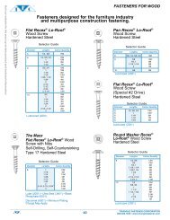
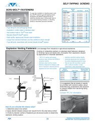
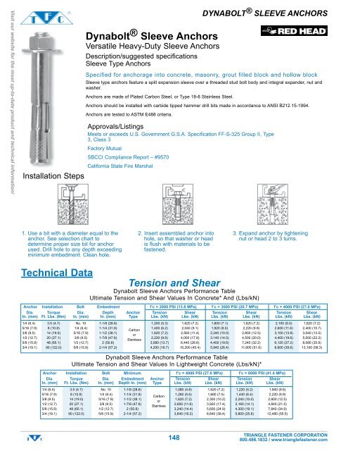
Visit our website for the most up-to-date product and technical information!Installation StepsDynabolt ® <strong>Sleeve</strong> <strong>Anchors</strong>Versatile Heavy-Duty <strong>Sleeve</strong> <strong>Anchors</strong>Description/suggested specifications<strong>Sleeve</strong> Type <strong>Anchors</strong>DYNABOLT ® SLEEVE ANCHORSSpecified for anchorage into concrete, masonry, grout filled block and hollow block<strong>Sleeve</strong> type anchors feature a split expansion sleeve over a threaded stud bolt body and integral expander, nut andwasher.<strong>Anchors</strong> are made of Plated Carbon Steel, or Type 18-8 Stainless Steel.<strong>Anchors</strong> should be installed with carbide tipped hammer drill bits made in accordance to ANSI B212.15-1994.<strong>Anchors</strong> are tested to ASTM E488 criteria.Approvals/ListingsMeets or exceeds U.S. Government G.S.A. Specification FF-S-325 Group II, Type3, Class 3Factory MutualSBCCI Compliance Report – #9570California State Fire Marshal1. Use a bit with a diameter equal to theanchor. See selection chart todetermine proper size bit for anchorused. Drill hole to any depth exceedingminimum embedment. Clean hole.2. Insert assembled anchor intohole, so that washer or headis flush with materials to befastened.3. Expand anchor by tighteningnut or head 2 to 3 turns.Technical DataTension and ShearDynabolt <strong>Sleeve</strong> <strong>Anchors</strong> Performance TableUltimate Tension and Shear Values In Concrete* And (Lbs/kN)Anchor Installation Bolt Embedment f’c = 2000 PSI (13.8 MPa) f’c = 3000 PSI (20.7 MPa) f’c = 4000 PSI (27.6 MPa)Dia. Torque Dia. Depth Anchor Tension Shear Tension Shear Tension ShearIn. (mm) Ft. Lbs. (Nm) In. (mm) In. (mm) Type Lbs. (kN) Lbs. (kN) Lbs. (kN) Lbs. (kN) Lbs. (kN) Lbs. (kN)1/4 (6.4) 3.5 (4.7) No. 10 1-1/8 (28.6) 1,200 (5.3) 1,620 (7.2) 1,600 (7.1) 1,620 (7.2) 2,100 (8.5) 1,620 (7.2)5/16 (7.9) 8 (10.8) 1/4 (6.4) 1-1/4 (31.8)Carbon1,400 (6.2) 2,040 (9.1) 1,920 (8.5) 2,220 (9.9) 2,600 (11.6) 2,400 (10.7)3/8 (9.5) 14 (19.0) 5/16 (7.9) 1-1/2 (38.1)or1,620 (7.2) 2,560 (11.4) 2,240 (10.0) 2,800 (12.5) 3,100 (13.8) 3,040 (13.5)1/2 (12.7) 20 (27.1) 3/8 (9.5) 1-7/8 (47.6)Stainless2,220 (9.9) 4,000 (17.8) 3,140 (14.0) 4,500 (20.0) 4,400 (19.6) 5,000 (22.2)5/8 (15.9) 48 (65.1) 1/2 (12.7) 2 (50.8) 3,080 (13.7) 6,440 (28.6) 4,400 (19.6) 7,240 (32.2) 6,120 (27.2) 8,080 (35.9)3/4 (19.1) 90 (122.0) 5/8 (15.9) 2-1/4 (57.2) 4,200 (18.7) 10,200 (45.4) 5,940 (26.4) 11,600 (51.6) 8,900 (39.6) 13,100 (58.3)Dynabolt <strong>Sleeve</strong> <strong>Anchors</strong> Performance TableUltimate Tension and Shear Values In Lightweight Concrete (Lbs/kN)*Anchor Installation Bolt Minimum f’c = 4000 PSI (27.6 MPa) f’c = 6000 PSI (41.4 MPa)Dia. Torque Dia. Embedment Anchor Tension Shear Tension ShearIn. (mm) Ft. Lbs. (Nm) In. (mm) Depth In. (mm) Type Lbs. (kN) Lbs. (kN) Lbs. (kN) Lbs. (kN)1/4 (6.4) 3.5 (4.7) No. 10 1-1/8 (28.6) 1,080 (4.8) 1,620 (7.2) 1,220 (5.2) 1,940 (8.6)5/16 (7.9) 8 (10.8) 1/4 (6.4) 1-1/4 (31.8)Carbon1,260 (5.6) 1,680 (7.5) 1,440 (6.4) 2,220 (9.9)3/8 (9.5) 14 (19.0) 5/16 (7.9) 1-1/2 (38.1)or1,620 (7.2) 2,300 (10.2) 2,240 (10.0) 2,800 (12.5)1/2 (12.7) 20 (27.1) 3/8 (9.5) 1-7/8 (47.6)Stainless2,600 (11.6) 3,920 (17.4) 3,160 (14.1) 4,840 (21.5)5/8 (15.9) 48 (65.1) 1/2 (12.7) 2 (50.8) 3,240 (14.4) 5,600 (24.9) 4,300 (19.1) 7,840 (34.9)3/4 (19.1) 90 (122.0) 5/8 (15.9) 2-1/4 (57.2) 3,640 (16.2) 8,640 (38.4) 5,800 (25.8) 12,480 (55.5)148TRIANGLE FASTENER CORPORATION800.486.1832 / www.trianglefastener.com
Dynabolt ® <strong>Sleeve</strong> <strong>Anchors</strong>Versatile Heavy-Duty <strong>Sleeve</strong> <strong>Anchors</strong>DYNABOLT ® SLEEVE ANCHORSSizesDynabolt Carbon SteelAnchorMax.Dia. & Thickness Qty/WtDrill Effective of Material PerBit Size Anchor Bolt Dia./ Minimum to be Qty/Wt MasterHead (Threads) Length* Threads Embedment Fastened Per Box CartonStyle Per Inch In. (mm) Per Inch In. (mm) In. (mm) Lbs. Lbs.Zinc Plating304 Stainless SteelAcorn Nut 1/4" - 20 5/8 (15.9) 3/16" /24 1/2 (12.7) 1/8 (3.2) 100/ 1.9 1000/ 20 1-3/8 (34.9) 3/16" /24 1-1/8 (28.6) 1/4 (6.4) 100/ 2.6 1000/ 27 2-1/4 (57.2) 3/16" /24 1-1/8 (28.6) 1-1/8 (28.6) 100/ 3.7 1000/ 38 Hex Nut 1/4" - 20 5/8 (15.9) 3/16" /24 1/2 (12.7) 1/8 (3.2) 100/ 1.6 1000/ 17 1-3/8 (34.9) 3/16" /24 1-1/8 (28.6) 1/4 (6.4) 100/ 2.3 1000/ 24 2-1/4 (57.2) 3/16" /24 1-1/8 (28.6) 1-1/8 (28.6) 100/ 3.4 1000/ 35 5/16" - 18 1-1/2 (38.1) 1/4" /20 1-1/4 (31.8) 1/4 (6.4) 100/ 4.0 1000/ 41 2-1/2 (63.5) 1/4" /20 1-1/4 (31.8) 1-1/4 (31.8) 100/ 5.9 800/ 47 3/8" - 16 1-7/8 (47.6) 5/16" /18 1-1/2 (38.1) 3/8 (9.5) 50/ 3.5 500/ 36 3 (76.2) 5/16" /18 1-1/2 (38.1) 1-1/2 (38.1) 50/ 4.9 400/ 40 1/2" - 13 2-1/4 (57.2) 3/8" /16 1-7/8 (47.6) 3/8 (9.5) 25/ 3.3 250/ 34 3 (76.2) 3/8" /16 1-7/8 (47.6) 1-1/8 (28.6) 25/ 4.0 200/ 33 4 (101.6) 3/8" /16 1-7/8 (47.6) 2-1/8 (54.0) 25/ 5.3 200/ 44 5/8" - 11 2-1/4 (57.2) 1/2" /13 2 (50.8) 1/4 (6.4) 25/ 6.3 150/ 38 3 (76.2) 1/2" /13 2 (50.8) 1 (25.4) 25/ 7.0 150/ 46 4-1/4 (108.0) 1/2" /13 2 (50.8) 2-1/4 (57.2) 10/ 3.9 100/ 41 6 (152.4) 1/2" /13 2 (50.8) 4 (101.6) 10/ 4.9 50/ 25 3/4" - 10 2-1/2 (63.5) 5/8" /11 2-1/4 (57.2) 1/4 (6.4) 10/ 4.7 50/ 25 4 (101.6) 5/8" /11 2-1/4 (57.2) 1-3/4 (44.5) 5/ 3.2 50/ 33 6-1/4 (158.8) 5/8" /11 2-1/4 (57.2) 4 (101.6) 5/ 4.3 50/ 44 Phillips 1/4" - 20 1-1/2 (38.1) 3/16" /24 1-1/8 (28.6) 3/8 (9.5) 100/ 1.9 1000/ 21 Flat Head (head dia. .477) 2-1/4 (57.2) 3/16" /24 1-1/8 (28.6) 1-1/8 (28.6) 100/ 2.7 1000/ 28 3-1/8 (79.4) 3/16" /24 1-1/8 (28.6) 2 (50.8) 100/ 3.8 1000/ 38 4 (101.6) 3/16" /24 1-1/8 (28.6) 2-7/8 (73.0) 100/ 4.7 1000/ 48 3/8" - 16 2-7/8 (73.0) 5/16" /18 1-1/2 (38.1) 1-3/8 (34.9) 50/ 3.8 500/ 40 (head dia. .722) 4 (101.6) 5/16" /18 1-1/2 (38.1) 2-1/2 (63.5) 50/ 5.3 400/ 4 5 (127.0) 5/16" /18 1-1/2 (38.1) 3-1/2 (88.9) 50/ 5.6 300/ 40 6 (152.4) 5/16" /18 1-1/2 (38.1) 4-1/2 (114.3) 50/ 8.0 300/ 48 Threshold 1/4" - 20 2-1/4 (57.2) 3/16" /24 1-1/8(28.6) 1-1/8 (28.6) 100/ 2.5 1000/ 25 Flat Head (head dia. .385) Round Head 1/4" - 20 1-3/8 (34.9) 3/16" /24 1-1/8 (28.6) 1/4 (6.4) 100/ 1.9 1000/ 20 2 (50.8) 3/16" /24 1-1/8 (28.6) 7/8 (22.2) 100/ 2.7 1000/ 28 2-7/8 (73.0) 3/16" /24 1-1/8 (28.6) 1-3/4 (44.5) 100/ 3.7 1000/ 38 3/8" - 16 2-5/8 (66.7) 5/16" /18 1-1/2 (38.1) 1-1/8 (28.6) 50/ 3.9 500/ 41 Tie Wire 5/16" - 18 1-1/2 (38.1) 1/4" /20 1-1/2 (38.1) 9/32 (7.1) 100/ 4.9 1000/ 50 Hex Coupling 3/8" - 16 1-7/8 (47.6) 3/8" /16 1-1/2 (38.1) -- -- 50/ 6.0 250/ 30 (Rod Hanger) Hanger 1/2" - 13 2-1/4 (57.2) 1/2" /13 1-7/8 (47.6) -- -- 25/ 6.5 125/ 34 HangerVisit our website for the most up-to-date product and technical information!Dynabolt <strong>Sleeve</strong> <strong>Anchors</strong> Performance TableUltimate Tension and Shear Values In Masonry Units (Lbs/kN)*Installation Lightweight Medium WeightAnchor Torque Bolt Minimum Anchor Hollow Core Grout Filled Hollow Core Grout FilledDia. Ft. Lbs. Dia. Embedment Type Tension Shear Tension Shear Tension Shear Tension ShearIn. (mm) (Nm) In. (mm) Depth In. (mm) (Steel) Lbs. (kN) Lbs. (kN) Lbs. (kN) Lbs. (kN) Lbs. (kN) Lbs. (kN) Lbs. (kN) Lbs. (kN)1/4 (6.4) 3.5 (4.7) 3/16 (4.8) 1-1/8 (28.6) Carbon 1,120 1,360 1,120 1,360 1,120 1,620 1,120 1,360(5.0) (6.0) (5.0) (6.0) (5.0) (7.2) (5.0) (6.0)Stainless 640 1,620 640 1,620 640 1,620 640 1,620(2.8) (7.2) (2.8) (7.2) (2.8) (7.2) (2.8) (7.2)3/8 (9.5) 15 (20.3) 5/16 (7.9) 1-1/2 (38.1) Carbon 1,360 2,560 1,360 2,560 1,360 2,560 1,360 2,560(6.0) (11.4) (6.0) (11.4) (6.0) (11.4) (6.0) (11.4)Stainless 1,160 2,560 1,160 2,560 1,160 2,560 1,160 2,560(5.2) (11.4) (5.2) (11.4) (5.2) (11.4) (5.2) (11.4)1/2 (12.7) 25 (33.9) 3/8 (9.5) 1-7/8 (47.6) Carbon -- -- 2,220 4,000 -- -- 2,220 4,000-- -- (9.9) (17.8) -- -- (9.9) (17.8)Stainless -- -- 2,100 4,000 -- -- 2,100 4,000-- -- (9.3) (17.8) -- -- (9.3) (17.8)5/8 (15.9) 55 (74.6) 1/2 (12.7) 2 (50.8) Carbon -- -- 3,080 6,440 -- -- 3,080 6,440-- -- (13.7) (28.6) -- -- (13.7) (28.6)Stainless -- -- 3,080 6,440 -- -- 2,820 6,440-- -- (13.7) (28.6) -- -- (12.5) (28.6)3/4 (19.1) 90 (122.0) 5/8 (15.9) 2-1/2 (63.5) Carbon -- -- 4,200 10,200 -- -- 4,200 10,200-- -- (18.7) (45.4) -- -- (18.7) (45.4)* Allowable values are based upon a 4 to 1 safety factor. Divide by 4 for allowable load values. The tabulated values are for anchors installed in a minimum of 12 diameters on center and aminimum edge distance of six diameters for 100 percent anchor efficiency. Spacing and edge distance may be reduced to six-diameter spacing and three-diameter edge distance,provided thevalues are reduced 50 percent. Linear interpolation may be used for intermediate spacings and edge distances.Combined Shear and Tension Loading—for Dynabolt <strong>Anchors</strong>Allowable loads for anchors subjected to combined shear and tension forces are determined by the following equation: (Ps/Pt) + (Vs/Vt)
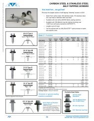
Visit our website for the most up-to-date product and technical information!Trubolt ® Wedge <strong>Anchors</strong>Dependable, Heavy-Duty, Inspectable, Wedge Type Expansion AnchorDescription/suggested specificationsWedge Type <strong>Anchors</strong>DYNABOLT ® WEDGE ANCHORSSpecified for anchorage into concrete.Wedge anchors feature a type 18-8 stainless steel split expansion ring and a threaded stud bolt body and integralcone expander, nut and washer. Anchor bodies are made of plated carbon steel, hot-dipped galvanized carbonsteel, type 304 stainless steel or type 316 stainless steel as identified in the drawings or other notations.The exposed end of the anchor is stamped to identify anchor length. Stampings should be preserved duringinstallation for any subsequent embedment verification.Use carbide tipped hammer drill bits made in accordance to ANSI B212.15-1994 to install anchors.<strong>Anchors</strong> are tested to ASTM E488 criteria and listed by ICBO and SBCCI. <strong>Anchors</strong> are listed by the followingagencies as required by the local building code: UL, FM, City of Los Angeles, California State Fire Marshal and CalTrans.Approvals/listings• Meets or exceeds U.S. Government G.S.A. Specification FF-S 325 Group II, Type 4, Class 1• Underwriters Laboratories• Factory Mutual• ICBO Evaluation Service, Inc. – #ER-1372 (including seismic loading conditions)• City of Los Angeles – #RR2748• SBCCI Compliance Report – #9570• California State Fire Marshal• Cal TransInstallation Steps• Using a bit whose diameter equalsthe anchor diameter, drill hole toany depth exceeding the minimumembedment. Clean hole.• Assemble anchor with nut andwasher so that the top of the nut isflush with the top of the anchor.Drive anchor through material to befastened so that nut and washer areflush with surface of material.• Expand anchor by tightening nut 3to 5 turns, or to the specific torquerequirement (see selection chart).150TRIANGLE FASTENER CORPORATION800.486.1832 / www.trianglefastener.com
SizesMax.Anchor Dia. Thickness Qty/wtThread & Drill Bit Overall of material Qty/Wt per masterLength Size (threads) Length to be fastened per box cartonIn. (mm) per inch In. (mm) In. (mm) lbs. lbs.3/4 (19.1) 1/4" - 20 1-3/4 (44.5) 3/8 (9.5) 100/ 3.1 1000/ 32 1-1/4 (31.8) 2-1/4 (57.2) 7/8 (22.2) 100/ 3.6 1000/ 37 2-1/4 (57.2) 3-1/4 (82.6) 1-7/8 (47.6) 100/ 4.7 800/ 39 1-1/8 (28.6) 3/8" - 16 2-1/4 (57.2) 3/8 (9.5) 50/ 4.1 500/ 41 1-5/8 (41.3) 2-3/4 (69.9) 7/8 (22.2) 50/ 4.7 400/ 39 1-7/8 (47.6) 3 (76.2) 1-1/8 (28.6) 50/ 5.0 400/ 41 2-5/8 (66.7) 3-3/4 (95.3) 1-7/8 (47.6) 50/ 5.9 300/ 36 2-3/4 (69.9) 5 (127.0) 3-1/8 (79.4) 50/ 7.4 250/ 38 2-1/4 (57.2) 7 (177.8) 5-1/8 (130.2) 50/ 10.4 250/ 53 1-1/4 (31.8) 1/2" - 13 2-3/4 (69.9) 1/8 (3.2) 25/ 4.6 200/ 38 2-1/4 (57.2) 3-3/4 (95.3) 1 (25.4) 25/ 5.7 150/ 35 2-3/4 (69.9) 4-1/4 (108.0) 1-1/2 (38.1) 25/ 6.2 150/ 38 3 (76.2) 4-1/2 (114.3) 1-3/4 (44.5) 25/ 6.5 150/ 39 3 (76.2) 5-1/2 (139.7) 2-3/4 (69.9) 25/ 7.7 150/ 47 4-1/2 (114.3) 7 (177.8) 4-1/4 (108.0) 25/ 9.3 150/ 57 1-3/4 (44.5) 5/8" - 11 3-1/2 (88.9) 1/8 (3.2) 10/ 3.6 100/ 37 2-1/2 (63.5) 4-1/4 (108.0) 7/8 (22.2) 10/ 4.1 100/ 42 3-1/4 (82.6) 5 (127.0) 1-5/8 (41.3) 10/ 4.7 100/ 48 3-1/2 (88.9) 6 (152.4) 2-5/8 (66.7) 10/ 5.4 50/ 28 4-1/2 (114.3) 7 (177.8) 3-5/8 (92.1) 10/ 6.2 30/ 19 3-1/2 (88.9) 8-1/2 (215.9) 5-1/8 (130.2) 10/ 8.0 30/ 25 1-3/4 (44.5) 10 (254.0) 6-5/8 (168.3) 10/ 9.4 30/ 29 1-3/4 (44.5) 3/4" - 10 4-1/4 (108.0) 1/4 (31.8) 10/ 6.8 60/ 42 2-1/4 (57.2) 4-3/4 (120.7) 3/4 (19.1) 10/ 7.4 60/ 45 3 (76.2) 5-1/2 (139.7) 1-1/2 (38.1) 10/ 8.1 50/ 41 3-3/4 (95.3) 6-1/4 (158.8) 2-1/4 (57.2) 10/ 9.1 30/ 28 4-1/2 (114.3) 7 (177.8) 3 (76.2) 10/ 9.7 30/ 30 3-1/2 (88.9) 8-1/2 (215.9) 4-1/2 (114.3) 10/ 12.3 30/ 38 1-3/4 (44.5) 10 (254.0) 6 152.4) 10/ 14.0 30/ 43 1-3/4 (44.5) 12 (304.8) 8 (203.2) 10/ 16.6 30/ 51 2-1/2 (63.5) 7/8" - 9 6 (152.4) 1-3/8 (34.9) 5/ 6.3 25/ 32 2-1/2 (63.5) 8 (203.2) 3-3/8 (85.7) 5/ 8.1 15/ 25 2-1/2 (63.5) 10 (254.0) 5-3/8 (136.5) 5/ 9.8 15/ 30 2-1/2 (63.5) 1" - 8 6 (152.4) 1/2 (12.7) 5/ 8.3 25/ 43 2-1/2 (63.5) 9 (228.6) 3-1/2 (88.9) 5/ 11.6 15/ 36 2-1/2 (63.5) 12 (304.8) 6-1/2 (165.1) 5/ 15.0 15/ 46 3-1/2 (88.9 1-1/4" - 7 9 (228.6) 5-1/4 (133.4) 5/ 18.0 15/ 55 Tie WireTruBolt Removable <strong>Anchors</strong> Selection ChartN/A 1/4" - 20 2-3/16 (55.6) 9/32 (7.1) 100/ 3.6 1000/ 36 DYNABOLT ® WEDGE ANCHORSTrubolt ® Wedge <strong>Anchors</strong>Dependable, Heavy-Duty, Inspectable, Wedge Type Expansion AnchorZinc PlatingHot-Dipped Galvanized304 Stainless Steel316 Stainless SteelVisit our website for the most up-to-date product and technical information!Meets ASTM B633 SC1, Type III specifications for electroplating of 5um = .0002" thickness.This material is well suited for non-corrosive environments.151TRIANGLE FASTENER CORPORATION800.486.1832 / www.trianglefastener.com
Visit our website for the most up-to-date product and technical information!Trubolt ® Wedge <strong>Anchors</strong>Dependable, Heavy-Duty, Inspectable, Wedge TypeExpansion AnchorTechnical DataTrubolt Wedge <strong>Anchors</strong> Performance TableUltimate Tension and Shear Values (Lbs/kN) In Concrete*Anchor Installation Embedment f’c = 2000 PSI (13.8 MPa) f’c = 4000 PSI (27.6 MPa) f’c = 6000 PSI (41.4 MPa)Dia. Torque Depth Anchor Tension Shear Tension Shear Tension ShearIn. (mm) Ft. Lbs. (Nm) In. (mm) Type Lbs. (kN) Lbs. (kN) Lbs. (kN) Lbs. (kN) Lbs. (kN) Lbs. (kN)1/4 (6.4) 8 (10.8) 1-1/8 (28.6) 1,180 (5.2) 1,400 (6.2) 1,780 (7.9) 1,400 (6.2) 1,900 (8.5) 1,400 (6.2)1-15/16 (49.2) 2,100 (9.3) 1,680 (7.5) 3,300 (14.7) 1.680 (7.5) 3,300 (14.7) 1,680 (7.5)2-1/8 (54.0) 2,260 (10.1) 3,300 (14.7) 3,300 (14.7)3/8 (9.5) 25 (33.9) 1-1/2 (38.1) Carbon 1,680 (7.5) 2,320 (10.3) 2,240 (10.0) 2,620 (11.7) 2,840 (12.6) 3,160 (14.1)3 (76.2) Steel 3,480 (15.5) 4,000 (17.8) 5,940 (26.4) 4,140 (18.4) 6,120 (27.2) 4,500 (20.0)4 (101.6) With 4,800 (21.4) 5,940 (26.4) 6,120 (27.2)1/2 (12.7) 55 (74.6) 2-1/4 (57.2) Zinc 4,660 (20.7) 4.760 (21.2) 5,100 (22.7) 4,760 (21.2) 7,040 (31.3) 7,040 (31.3)4-1/8 (104.8) Plating 4,660 (20.7) 7,240 (32.2) 9,640 (42.9) 7,240 (32.2) 10,820 (48.1) 8,160 (36.3)6 (152.4) or 5,340 (23.8) 9,640 (42.9) 10,820 (48.1)5/8 (15.9) 90 (122.0) 2-3/4 (69.9) Carbon 6,580 (29.3) 7,121 (31.7) 7,180 (31.9) 7,120 (31.7) 9,720 (43.2) 9,616 (42.8)5-1/8 (130.2) Steel 6,580 (29.3) 9,600 (42.7) 14,920 (66.4) 11,900(52.9) 16,380(72.9) 12,520(55.7)7-1/2 (190.5) With 7,060 (31.4) 15,020 (66.8) 16,380 (72.9)3/4 (19.1) 175 (237.3) 3-1/4(82.6) Hot-Dipped 7,120 (31.7) 10,120 (45.0) 10,840 (48.2) 13,720 (61.0) 13,300 (59.2) 15,980 (71.1)6-5/8 (168.3) Galvanizing 10,980 (48.8) 20,320 (90.4) 17,700 (78.7) 23,740 (105.6) 20,260 (90.1) 23,740 (105.6)10 (254.0) or 10,980 (48.8) 17,880 (79.5) 23,580 (104.9)7/8 (22.2) 250 (339.0) 3-3/4 (95.3) Type 304 9,520 (42.3) 13,160 (58.5) 14,740 (65.6) 16,580 (73.8) 17,420 (77.5) 19,160 (85.2)6-1/4 (158.8) Stainless 14,660 (65.2) 20,880 (92.9) 20,940 (93.1) 28,800 (128.1) 24,360 (108.4) 28,800 (128.1)8 (203.2) Steel 14,660 (65.2) 20,940 (93.1) 24,360 (108.4)1 (25.4) 300 (406.7) 4-1/2 (114.3) or 13,940 (62.0) 16,080 (71.5) 20,180 (89.8) 22,820 (101.5) 21,180 (94.2) 24,480 (108.9)7-3/8 (187.3) 14,600 (64.9) 28,680 (127.6) 23,980 (106.7) 37,940 (168.8) 33,260 (148.0) 38,080 (169.4)Type 3169-1/2 (241.3) 18,700 (83.2) 26,540 (118.1) 33,260 (148.0)Stainless1-1/4 (31.8) 500 (677.9) 5-1/2 (139.7) Steel 18,140 (80.7) 23,280 103.6) 26,380 (117.3) 29,460 (131.0) 33,640 (149.6) 33,780 (150.3)8 (203.2) 27,340 (121.6) 35,080 (156.0) 43,300 (192.6) 44,260 (196.9) 45,540 (202.6) 50,560 (224.9)* Allowable values are based upon a 4 to 1 safety factor. Divide by 4 for allowable load values.DYNABOLT ® WEDGE ANCHORSTrubolt Wedge <strong>Anchors</strong> Performance TableUltimate Tension and Shear Values (Lbs/kN) In Lightweight Concrete*Lower Flute Of Steel Deck withLightweight ConcreteLightweight Concrete FillAnchor Installation Embedment f’c = 3000 PSI (20.7 MPa) f’c = 3000 PSI (20.7 MPa)DIA. Torque Depth Anchor Tension Shear Tension ShearIn. (mm) Ft. Lbs. (Nm) In. (mm) Type Lbs. (kN) Lbs. (kN) Lbs. (kN) Lbs. (kN)3/8 (9.5) 25 (33.9) 1-1/2 (38.1) 2,120 (9.4) 3,720 (16.5) 1,900 (8.5) 3,160 (14.1)3 (76.2) Carbon Steel With 2,940 (13.1) 4,240 (18.9) 2,840 (12.6) 4,000 (17.8)Zinc Plating or1/2 (12.7) 55 (74.6) 2-1/4 (57.2) 3,600 (16.0) 7,040 (31.3) 3,400 (15.1) 5,380 (23.9)Carbon Steel With3 (76.2) 4,720 (21.0) 6,620 (29.4) 4,480 (19.9) 6,620 (29.4)Hot-Dipped4 (101.6) -- -- 6,920 (30.8) 4,800 (21.4) 6,440 (28.6)Galvanizing or5/8 (15.9) 90 (122.0) 3 (76.2) Type 304 Stainless 6,000 (26.7) 9,240 (41.1) 4,720 (21.0) 5,500 (24.5)5 (127.0) Steel or Type 316 5,960 (26.5) 9,280 (41.3) 6,580 (29.3) 9,140 (40.7)3/4 (19.1) 175 (237.3) 3-1/4 (82.6) Stainless Steel 7,160 (31.9) 12,600 (56.0) 5,840 (26.0) 8,880 (39.5)5-1/4 (133.4) 8,900 (39.6) 15,920 (70.8) 7,040 (31.3) -- --* Allowable values are based upon a 4 to 1 safety factor. Divide by 4 for allowable load values.152TRIANGLE FASTENER CORPORATION800.486.1832 / www.trianglefastener.com
DYNABOLT ® WEDGE ANCHORSTechnical DataTrubolt Wedge <strong>Anchors</strong> Performance TableRecommended Spacing And Edge Distance Requirements For Shear Loads*Edge Distance Min. Edge Min. Edge Distance Spacing Min. AllowableRequired To Distance At Which At Which The Required to Spacing BetweenAnchor Embedment Obtain Max. The Load Factor Load Factor Obtain Max. <strong>Anchors</strong> In. (mm)Dia. Depth Anchor Working Load Applied = .60 Applied = .20 Working Load Load FactorIn. (mm) In. (mm) Type In. (mm) In. (mm) In. (mm) In. (mm) Applied = .401/4 (6.4) 1-1/8 (28.6) 2 (50.8) 1-5/16 (33.3) -- -- 3-15/16 (100.0) 2 (50.8)1-15/16 (49.2) 1-15/16 (49.2) 1 (25.4) -- -- 3-7/8 (98.4) 1-15/16 (49.2)3/8 (9.5)Carbon Steel With1-1/2 (38.1) 2-5/8 (66.7) 1-3/4 (44.5) -- -- 5-1/4 (133.4) 2-5/8 (66.7)Zinc Plating3 (76.2) 3-3/4 (95.3) 3 (76.2) 1-1/2 (38.1) 6 (152.4) 3 (76.2)1/2 (12.7) 2-1/4 (57.2)or3-15/16 (100.0) 2-9/16 (65.1) -- -- 7-7/8 (200.0) 3-15/16 (100.0)4-1/8 (104.8) 5-3/16 (131.8) 3-1/8 (79.4) 1-9/16 (39.7) 6-3/16 (157.2) 3-1/8 (79.4)Carbon Steel With5/8 (15.9) 2-3/4 (69.9) 4-13/16 (122.2) 3-1/8 (79.4) -- -- 9-5/8 (244.5) 4-13/16 (122.2)Hot-Dipped5-1/8 (130.2) 6-7/16 (163.5) 3-7/8 (98.4) 1-15/16 (49.2) 7-11/16 (195.3) 3-7/8 (98.4)Galvanizing3/4 (19.1) 3-1/4 (82.6) 5-11/16 (144.5) 3-3/4 (95.3) -- -- 11-3/8 (288.9) 5-11/16 (144.5)or6-5/8 (168.3) 6-5/16 (160.3) 5 (127.0) 2-1/2 (63.5) 9-15/16 (252.4) 5 (127.0)Type 304 Stainless7/8 (22.2) 3-3/4 (95.3) Steel6-9/16 (166.7) 4-5/16 (109.5) -- -- 13-1/8 (333.4) 6-9/16 (166.7)6-1/4 (158.8)or8-1/2 (215.9) 6-1/4 (158.8) 3-1/8 (79.4) 12-1/2 (317.5) 6-1/4 (158.8)1 (25.4) 4-1/4 (108.0) 7-7/8 (200.0) 5-1/8 (130.2) -- -- 15-3/4 (400.1) 7-7/8 (200.0)Type 3167-3/8 (187.3) 10-1/16 (255.6) 7-3/8 (187.3) 3-11/16 (93.7) 14-3/4 (374.7) 7-3/8 (187.3)Stainless Steel1-1/4 (31.8) 5-1/2 (139.7) 9-5/8 (244.5) 6-1/4 (158.8) -- -- 19-1/4 (489.0) 9-5/8 (244.5)8 (203.2) 11-7/16 (290.5) 8 (203.2) 4 (101.6) 16 (406.4) 8 (203.2)* Spacing and edge distances shall be divided by 0.75 when anchors are placed in structural lightweight concrete. Linear interpolation may be used for intermediate spacing and edge distances.Visit our website for the most up-to-date product and technical information!Trubolt Wedge <strong>Anchors</strong> Performance TableRecommended Spacing and Edge Distance Requirements for Tension Loads*Edge Distance Min. Allowable Min. AllowableRequired To Edge Distance At Spacing Required Spacing At WhichAnchor Embedment Obtain Max. Which The Load To Obtain Max. The Load FactorDia. Depth Anchor Working Load Factor Applied = .65 Working Load Applied = .70In. (mm) In. (mm) Type In. (mm) In. (mm) In. (mm) In. (mm)1/4 (6.4) 1-1/8 (28.6) 2 (50.8) 1 (25.4) 3-15/16 (100.0) 2 (50.8)1-15/16 (49.2) 1-15/16 (49.2) 1 (25.4) 3-7/8 (98.4) 1-15/16 (49.2)2-1/8 (54.0) 1-5/8 (41.3) 13/16 (20.6) 3-3/16 (81.0) 1-5/8 (41.3)3/8 (9.5) 1-1/2 (38.1) 2-5/8 (66.7) 1-5/16 (33.3) 5-1/4 (133.4) 2-5/8 (66.7)3 (76.2) 3 (76.2) 1-1/2 (38.1) 6 (152.4) 3 (76.2)4 (101.6)Carbon Steel With3 (76.2) 1-1/2 (38.1) 6 (152.4) 3 (76.2)1/2 (12.7) 2-1/4 (57.2) Zinc Plating 3-15/16 (100.0) 2 (50.8) 7-7/8 (200.0) 3-15/16 (100.0)4-1/8 (104.8)or3-1/8 (79.4) 1-9/16 (39.7) 6-3/16 (157.2) 3-1/8 (79.4)6 (152.4) 4-1/2 (114.3) 2-1/4 (57.2) 9 (228.6) 4-1/2 (114.3)Carbon Steel With5/8 (15.9) 2-3/4 (69.9)Hot-Dipped4-13/16 (122.2) 2-7/16 (61.9) 9-5/8 (244.5) 4-13/16 (122.2)5-1/8 (130.2)Galvanizing3-7/8 (98.4) 1-15/16 (49.2) 7-1/16 (195.3) 3-7/8 (98.4)7-1/2 (190.5) 5-5/8 (142.9) 2-13/16 (71.4) 11-1/4 (285.8) 5-5/8 (142.9)or3/4 (19.1) 3-1/4 (82.6) 5-11/16 (144.5) 2-7/8 (73.0) 11-3/8 (288.9) 5-11/16 (144.5)6-5/8 (168.3) Type 304 Stainless 5 (127.0) 2-1/2 (63.5) 9-15/16 (252.4) 5 (127.0)10 (254.0) Steel7-1/2 (190.5) 3-3/4 (95.3) 15 (381.0) 7-1/2 (190.5)7/8 (22.2) 3-3/4 (95.3) or6-9/16 (166.7) 3-5/16 (84.1) 13-1/8 (333.4) 6-9/16 (166.7)6-1/4 (158.8) Type 3166-1/4 (158.8) 3-1/8 (79.4) 12-1/2 (317.5) 6-1/4 (158.8)8 (203.2) Stainless Steel6 (152.4) 3 (76.2) 12 (304.8) 6 (152.4)1 (25.4) 4-1/2 (114.3) 7-7/8 (200.0) 3-15/16 (100.0) 15-3/4 (400.1) 7-7/8 (200.0)7-3/8 (187.3) 7-3/8 (187.3) 3-11/16 (93.7) 14-3/4 (374.7) 7-3/8 (187.3)9-1/2 (241.3) 7-1/8 (181.0) 3-9/16 (90.5) 14-1/4 (362.0) 7-1/8 (181.0)1-1/4 (31.8) 5-1/2 (139.7) 9-5/8 (244.5) 4-13/16 (122.2) 19-1/4 (489.0) 9-5/8 (244.5)8 (203.2) 8 (203.2) 4 (101.6) 16 (406.4) 8 (203.2)* Spacing and edge distances shall be divided by 0.75 when anchors are placed in structural lightweight concrete. Linear interpolation may be used for intermediate spacing and edge distances.Combined Shear and Tension Loading for Trubolt <strong>Anchors</strong>Allowable loads for anchors subjected to combined shear and tension forces are determined by the following equation:(Ps/Pt)5/3 + (Vs/Vt)5/3 ≤ 1Ps = Applied tension load Vs = Applied shear load Pt = Allowable tension load Vt = Allowable shear load153TRIANGLE FASTENER CORPORATION800.486.1832 / www.trianglefastener.com