Phase coherent crossover networks - First Watt
Phase coherent crossover networks - First Watt
Phase coherent crossover networks - First Watt

You also want an ePaper? Increase the reach of your titles
YUMPU automatically turns print PDFs into web optimized ePapers that Google loves.
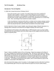
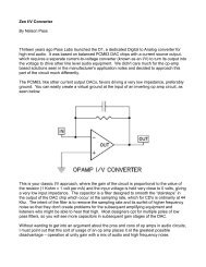
SIMPLE BUT EFFECTIVE.In applications where the drivers have wide bandwidth and cantolerate the low rolloff rate, the6dB/octave <strong>crossover</strong> can giveexcellent results, particularly with planar drivers, such aselectrostatic systems and Magnepans.The circuit of Fig. 4 has given me excellent results with theTympani 1D's and MG 2A's and serves as a good example ofhow well simple inexpensive approaches work. I have not hadthe opportunity to try it with their newer SMG's, but I expectsimilar improvements over the stock systems. Using bothcapacitors and coils, it presents a flat input impedance of10kohm or higher.possible. IC buffers (such as the LM 302 or LM 310) op amps(whose output is connected to the inverting input), and simpleone-device emitter/source/cathode voltage followers withoutnegative feedback are suitable. The circuits of Figs. 4-6 all passour square wave test and all have6dB/octave slopes.SUMMING FOR FLAT RESPONSE.Even more interesting is the technique illustrated in Fig. 7. Anactive circuit assembles a phase complementary output from thedifference between the input and the output of a single filter. Thisensures that the sum of the two outputs will be perfectly flat inamplitude and phase. To be effective, the filter should exhibitunity gain in its passband, or the rolloff characteristic will have ashelf hike a conventional tone controll, but otherwise it can beany type of filter.Those who wish to dispense with coils and whose preamp candrive a 5kohm load might try the equivalent circuit of Fig. 5,which gives the same results with a few decibels loss of gain.The circuit of Fig. 6 (which uses active impedance buffers to givethe circuit a very high input impedance and a very low outputimpedance) does not have this loss. Various types of buffers areThis approach allows the use of higher order filter slopes in aphase <strong>coherent</strong> <strong>crossover</strong> as shown in Fig. 8, where we notesome interesting phenomena. The precise complement of amaximally flat 12or 18dB/octave filter has a peak whichincreases with the slope and Q of the filter, and it always exhibitsa 6dB/octave slope. One of these minor drawbacks, the peak,
Unfortunately, I don't know of a way thecomplementary output can be made to rolloff at a slope greater than6dB/octave, andyou must choose whether it will be the lowpass or the high pass based oninformation about the drivers. Most of thetime you should assign the higher slope tothe tweeter, since it generally needs moreprotection from out of band signals.In such filters, the resistances in thedifferencing amplifier must be very muchgreater than the output impedance of thefilter. Figure 11 shows what happens whenthey are only 5 times greater: the rolloffcurve shelves at about -20dB.This is not avery desirable characteristic, but often it isnot very practical to place multimegohmresistances in the differencing circuitbecause of the noise and the input biascurrents of the op amp. Figure12 showsan easy solution to this potential problem.Buffering the output of the filter gives it anear-zero output impedance, andcompletely eliminates this effect.TOTAL SYSTEM RESPONSE.can be reduced by lowering the Q of the filter as in the examplesof Fig. 9 where the less than maximally flat characteristics arethose of Fig. 2.Figure 10 shows us that the effect is similar but reversed if youuse a low pass filter in this configuration instead of a high pass.So far we have considered only the phaseand amplitude performance of the<strong>crossover</strong> network and how easily you canachieve phase coherency in such adevice. However Mother Nature is not going to let us off solightly. These <strong>networks</strong> drive loudspeaker elements and while wecan make filters perfect, the acoustic sum includes the phaseand amplitude distortions of the drivers. Robert Bullock'sinteresting work on the sensitivity of conventional <strong>crossover</strong><strong>networks</strong> to the imperfections of drivers inspired me to examinephase <strong>coherent</strong> filters for the samephenomena.The computer model for two differenttweeters and two different woofers shownin Fig.13 is consistent with our previousanalysis of the mass controlled piston.One case allows for a one octave marginbetween the drivers' rolloffs and the<strong>crossover</strong> point (500Hz for the tweeter,2000Hz for the woofer, and 1000Hz<strong>crossover</strong>), and the second case allows fora two octave margin. The actual acousticaloutput is the sum of the <strong>crossover</strong> anddriver characteristics. I tried variouscombinations in the computer model andfound (Fig. 14) that severe amplitude andphase distortion occur in all cases.Does this mean that phase <strong>coherent</strong><strong>crossover</strong>s are useless? Not necessarily.
Examples of these filters have been known to work well,particularly with planar drivers, which are not precisely modeledas pistons, and do not exhibit the severe amplitude anomalieswe might expect. However, note that while the filter may beadvertised honestly as phase <strong>coherent</strong> this does not guaranteethe system will be also, and I recommend carefully auditioningsuch a <strong>crossover</strong> with the intended loudspeaker. The point is tomake the final acoustical response phase linear. The <strong>crossover</strong>smust be designed to compensate for the drivers' performance ifthe final output is to be flat.Much remains to be done in this area. The simulations can beperformed using some of the excellent linear circuit analysisprograms commercially available for the Apple, Hewlett-Packard, and other microcomputers, and I would be interested inany results readers may obtain.