The Zen Variations - Part 5 - First Watt
The Zen Variations - Part 5 - First Watt
The Zen Variations - Part 5 - First Watt

You also want an ePaper? Increase the reach of your titles
YUMPU automatically turns print PDFs into web optimized ePapers that Google loves.
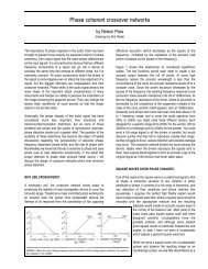
same input signal, but becauseone is an N channel device andthe other a P channel type device,their reactions to the input areopposite. If the input voltage ispositive in polarity, Q1 conductsless and Q2 conducts more, andthe output voltage goes negative,making this an inverting typeamplifier.R1 and R2 form the input andfeedback network of the amplifier,and the gain of the circuit willbe slightly less than the ratio ofR2/R1. On the positive side, R3and R5 form a network that setsup the proper DC voltage bias forthe Gate of Q2, meaning 3 to 4volts across R3. Similarly on thenegative half, R4 and R6 set upbias for the Gate of Q1. C1 andC2 conduct the input signal tothe Gates of these Mosfets whileblocking this DC Gate bias.More <strong>Part</strong>s!Figure 2 will work just fine as is,but it’s usually more convenientto add some little touches forextra stability. Figure 3 shows amore detailed schematic designedto make life easier for those ofyou fearless enough to build thisamplifier (and I certainly hopeyou do). <strong>First</strong> off, we never useMosfets without some resistancein series with the Gate pins, elsethey might just fly away withparasitic high frequency oscillationall by themselves, and so wehave R7 and R8 to damp out thatpossibility. <strong>The</strong> value is not at allcritical - somewhere between 100and 500 ohms will do the job.Also, you will notice that we haveadded Source pin power resistorsto Q1 and Q2. <strong>The</strong>se help stabilizethe DC bias a bit, and also give usconvenient spots across whichwe can measure the current flowthrough the circuit. In this case, Ihave chosen two parallel .47 ohm3 watt resistors to form a 6 watt.235 ohm resistor (because theDigikey catalog only offers theinexpensive metal film Panasonicpower resistors down to .47ohms). Like the Gate resistors, awide range of values will work fine.Fig. 3 Complementary <strong>Zen</strong>I suggest between .1 and .5 ohm,keeping in mind that they shouldbe able to handle as much as 4amps without overheating. All therest of the resistors will be happyat .25 watt ratings, and none ofthem are critical in value exceptR3 and R4.In a real amplifier, R3 and R4assume critical values, as theyPass D.I.Y Project: <strong>Zen</strong> <strong>Variations</strong> - part 5page 3
sensitively control the bias currentthrough the amplifier. We wantthis bias current to be in a welldefinedrange, as it bears stronglyupon the performance and alsothe heat dissipation of the circuit.Too little bias current gives highdistortion, and too much will cookthe transistors. As a consequence,R3 and R4 are adjustable resistors(potentiometers) which will beused to set up the bias currentexactly when the finished amplifieris first tested.Note in Figure 3 that C1 and C2have now assumed some valuesand are polarized electrolytic typecapacitors. I have no objection tofilm type capacitors, nor is thereany reason not to bypass the47 uF electrolytic caps with yourfavorite lower value film types. C1and C2 should be rated at least thevalue of the supply voltage, and Irecommend 35 volts minimum forthis project.Q1 and Q2 are not particularlycritical as to type. I use IRFP240and IRFP9240 as they work fine,are commonly available and nottoo expensive. Many other typeswill work fine. Matching of Q1 andQ2 is not important.<strong>The</strong> heat sinking for Q1 and Q2will be an important issue, as weintend to run them between 30and 75 watts each, dependingon the supply and bias. This issomewhat higher than we haveseen in the other <strong>Zen</strong> projects,and even more effort will have togo into keeping these devices atreliable temperatures. In general,we can accept 50 to 60 degrees C.on the heat sink near the transistormounting point.<strong>The</strong> circuit of Figure 3 is quitesensitive to power supply noiseand fluctuation. V+ and V- willneed to be stable and quiet,otherwise the bias will wander andnoise will appear at the output ofthe amplifier.Performance AnxietyWe built up two separate channelsof the circuit of Figure 3 and ran aseries of bench tests, measuringcharacteristics at different supplyvoltages and bias points.Fig. 4 Distortion vs Power20V supply rails.Figure 4 shows the Total HarmonicDistortion and Noise (THD+N)for the amplifier, measured at 1KHz and driving 8 ohms. <strong>The</strong>regulated supply voltages V+ andV- have been set at 20 volts each,and three separate curves havebeen run, showing THD+N versusoutput power in watts for biascurrents of 1.5 amps, 2.0 amps,and 2.5 amps. <strong>The</strong>se bias figurescreate heat dissipation for eachdevice at about 30 watts, 40 watts,and 50 watts, respectively.Fig. 5 Distortion vs Power25V supply rails.Pass D.I.Y Project: <strong>Zen</strong> <strong>Variations</strong> - part 5page 4
Fig. 6 Distortion vs Power30V supply rails.Fig. 6 Distortion vs Freqencyspite of this being a complementarycircuit, and reflects the imprecisematching of the complementarydevices. Because the devicesare slightly different in gainvariations, asymmetry appears inthe distortion waveform, creatingeven order harmonics. At powerlevels above a couple watts, thirdharmonic and other odd harmoniccomponents start to dominate,and of course at some point thecircuit simply clips pretty much likeany other amp.Figure 7 shows the THD plus noisefrom 20 Hz to 20 KHz measured at1 watt and without filtering. <strong>The</strong>distortion climbs at the highestfrequencies and is essentiallydoubled at 20 KHz. <strong>The</strong> frequencyresponse was measured as – 3dBat about 10 Hz and 100,000 Hz.<strong>The</strong> output impedance of theamplifier is relatively high,approximately 2 ohms, giving adamping factor of about 4. Thisis gain dependent, and improvesinversely with gain, so that ahigher value of R1 proportionatelyincreases the damping factor.Figure 5 shows the THD+N forthe amplifier with the regulatedsupply voltages V+ and V- at 25volts each and bias currents of 1.5amps, 2.0 amps, and 2.5 amps,dissipating about 37 watts, 50watts, and 62 watts, respectivelyfor each transistor.In Figure 6 we see the same test,but with the supply voltages raisedto +/- 30 volts, and the dissipationat about 45 watts, 60 watts, and75 watts for each transistor.From these curves we findperformance that is roughly similarto the <strong>Zen</strong> <strong>Variations</strong> 2 project,with a bit more distortion but alsoa bit more power. <strong>The</strong>re is nota lot of variation in performancebetween 1.5 amp, 2.0 amp and2.5 amp bias, although the higherbias tends to sound better and isalso better with low impedanceloads. Bias at only 1.0 amp gavemuch higher distortion under allconditions, and so 1.5 amps isthe minimum recommended biascurrent.<strong>The</strong> harmonic character ofdistortion is primarily secondharmonic at lower wattages, inQuiet, Please<strong>The</strong> ZV5 is much more sensitive tosupply noise than other amplifiers,and this is because the input ACsignal is referenced not to ground,but to the AC value of the supplyrails. To the extent that the supplyripple noise is symmetric, thereis some cancellation, but whatremains is still amplified by thegain of the amplifier. Typically youwill find that the value of the noiseon the supply is comparable to thenoise that appears at the output.This means that theComplementary <strong>Zen</strong> requires aPass D.I.Y Project: <strong>Zen</strong> <strong>Variations</strong> - part 5page 5
very quiet supply. Given a quietsupply however, the noise figuresare astonishingly good on oursamples; on the order of 18 uVover the audio band. As a rule,commercial manufacturers arehappy with 10 times that amount.Providing the appropriate supplyfor this circuit is an exercise in bighardware. Usually when we saythis we mean big transformers,capacitors and heat sinks, butin this case we mostly mean bigcapacitors.Alternatively, you could designan active supply using switching,feedback and other techniques toget the appropriate voltage andcurrent at the noise levels youwant. What you want is a sourceimpedance around .05 ohms orless and noise around 10 uV orless. I leave this approach asan exercise for the reader; in thisarticle we are going to do it the bigdumb way.Figure 8 shows the schematic ofsuch a power supply. In manyways this is typical of the powersupplies for the <strong>Zen</strong> amps, but ituses all the tricks to get low noiseand low source impedance. Bigas it is, this supply is meant forone channel only, as any signalimpressed on the supply by onechannel will show up on the otherchannel.Primary SchoolBecause the design of thiscircuit is flexible enough to takeadvantage of a range of supplylevels, we cannot specify aparticular transformer, and so wewill go through a quick exercise todetermine what we need.<strong>The</strong> power transformer will needto have the voltage and currentrating appropriate to the draw ofthe circuit. In general, you shoulduse a transformer whose VA ratingis more than twice that of thecircuit draw.<strong>The</strong> rule-of-thumb formula for theselection of the transformer is asfollows:VA rating (watts) = 2.5 * 2 *(regulated voltage + 8) * biascurrentFor the example of +/- 20 volts at1.5 amps (the smallest example)we get:VA = 2.5 * 2 * (20 + 8) * 1.5 = 210wattsFor the example of +/- 30 volts at2.5 amps (the largest example):VA = 2.5 * 2 * (30 + 8) * 2.5 = 475wattsRemember, this is per eachchannel!Secondary SchoolWe want the unregulated supplycoming off bridge rectifiers B1 andB2 to be about 8 volts higher thanthe desired regulated supply, andthat is why you see the number8 added to the regulated voltagein the above calculation. Of this8 volts, about a volt will be lostto ripple, about a volt will be lostto DC across the inductors L1 orL2, about 4 volts will be lost fromthe Gate to Source of regulatortransistors Q3 and Q4, and the 2volts left over will be needed torun a couple of milliamps currentthrough R13 and R14 to drive the<strong>Zen</strong>er diodes Z1 and Z2.A simple way to calculate thesecondary voltages required is tostart with the regulated rail voltage,add the 8 volts, add another 3 voltsfor Bridge and <strong>The</strong>rmistor losses,and divide by 1.4, which will giveyou the AC voltage rating of eachsecondary winding. For the 20Volt example, we have (20 + 8 +3) / 1.4 which gives 22 V AC.This figure should be under load,in other words this transformershould deliver this secondaryvoltage while operated at 200watts. If a 10% regulation figureis called out on the transformerspecs, then consider adding 10%to that 22 V AC. When in doubt,buy a heavier transformer with abigger VA rating.You may not get exactly thevoltage that you want, but this isnot likely to be a real problem.You may have to adjust yourexpectations for the voltage ratingof the <strong>Zen</strong>er diodes Z1 and Z2to be about 2 volts less than thevoltage appearing at the Drainsof Q3 and Q4, and everything willprobably be fine. If you want thedifference voltage to be other thanthe 2 volts, adjust R13 and R14so that the current flowing throughthem to the <strong>Zen</strong>er diodes is about2 mA.Fuse F1 is standard Slow Blowtype rated at 4 amps or so (for120V operation). If this provesto be too small, then try 5 amps.If you are running 240 VAC linepower, then you will want to halvethat figure, as well as running thetransformer primary coils in seriesrather than parallel.S1 should be a nice big high currentrated switch. While it’s true thatthermistor TH1 will help reducelarge turn-on current surges, thePass D.I.Y Project: <strong>Zen</strong> <strong>Variations</strong> - part 5page 6
ating of the switch should be at25 amps and 250 volts or better.<strong>The</strong>rmistor TH1 is a KeystoneCL60 type, rated at 5 amps steadystate current. Of course you canleave both the switch and/or thethermistor out if you wish, they arenot truly required for operation.C3 should be a line-ratedcapacitor, designed to sit acrossan AC power line in safety. Youcan leave it out also, if you wish.B3 is a power diode bridge, andcan be rated the same as B1 andB2, which are 35 amp at 200 voltsor so. B1 and B2 clearly have thefunction of rectifying the secondaryAC voltage into the unregulatedrails. Some of you will wish toexplore the variety of higher-endtypes of diodes that are availablefor this purpose, and of courseyou are encouraged to do so. <strong>The</strong>prototype was built with big dumbcheap rectifier bridges with nopretension whatsoever.In the case of B3, the function isto provide a connection to Earthground (the one provided by yourAC outlet) with a small voltagebarrier to prevent the everpresentground loop that hauntsmany systems. If your internalground starts exceeding about .6volts above Earth ground, B3 willconduct it off to Earth, hopefullykeeping you safe from shock incase of transformer failure or someother mishap which makes theground more lively than is wanted.<strong>The</strong>re are other approaches,and perhaps you can bypass B3altogether without picking up noise,but for safety reasons you shouldnever disable the Earth groundconnection of your system. Youwill note in Figure 8 that provisionis made on B3 for connection tothe ground of another channelsharing the same chassis. If thereis no other channel sharing thesame chassis, you can leave thispin unconnected, or better yet,attach it to the same circuit groundas the other pin.Capacitors C4 through C8 arerated at about 30,000 uF (ormore!) at a voltage exceedingthe unregulated rail voltage(remember: regulated voltage+ 8 volts). You cannot skimptoo much on these capacitancevalues and still get a sufficientlyquiet supply for this amplifier. Youcan parallel smaller values if youlike, and of course you can addthe always popular film capacitorsfor additional bypass.Regulation Rules<strong>The</strong> Mosfet regulators in thiscircuit are simply followers, drivenby the voltage appearing at theirGates. On a long term DC basisthis is determined by the valueof the <strong>Zen</strong>er diodes, but fairlylarge capacitors C10 and C11are provided not only to helpfilter noise, but to provide a veryslow startup voltage. ZV5 candraw quite a bit of extra current ifawakened rapidly due to C1 andC2, and so the 2200 uF values forC10 and C11 give it a gentle wakeupcall.You might imagine that largePass D.I.Y Project: <strong>Zen</strong> <strong>Variations</strong> - part 5page 7
capacitance would not be neededcoming off the output of the Mosfetregulators, but in fact they are.Q3 and Q4 are operated withoutfeedback, and their intrinsic“resistance” (the inverse of theirtransconductance) is about .25ohms, enough to create someundesirable modulation at ACfrequencies. This is squashed bythe 30,000 uF of C8 and C9 so thatit doesn’t become an issue untildown about 10 Hz or so, and bythen your woofer has much biggerproblems than the amplifier.We note that <strong>Zen</strong>er diodes Z1 andZ2 are chosen to be 4 volts higherthan the regulated voltage desired.<strong>The</strong> appropriate voltages can beformed by placing <strong>Zen</strong>er diodesin series, but the dissipationexperienced by each diode shouldbe considered. Typically, each<strong>Zen</strong>er diode will have about 2 mAcurrent running through it, and thismultiplied by the <strong>Zen</strong>er voltageforms the dissipation figure. Forexample, a 34 volt <strong>Zen</strong>er with2 mA current dissipates 78 mW(.078 watts). A nice .5 watt <strong>Zen</strong>erdiode would do well here, andwould be unlikely to break.Diode D1 and D2 are providedto drain off C10 and C11 quicklywhen the power is turned off, elsethe 20 Volt Gate to Source ratingsof Q3 and Q4 might be exceeded.<strong>The</strong> particular characteristics ofL1 and L2 are not very important.<strong>The</strong>y simply need to hold about2 mH of inductance at a DCcurrent up to 3 amps or so withoutsaturating or burning up. Yourstandard big coil with fat wire willdo the job, and remember not tolocate it near the amplifier’s input.If fact, with the exception of C8 andC9, the power supply in general isbest kept at a distance from theaudio portion of the circuit. Noneed to get carried away, a foot orso usually does the trick.Bias ChoicesIn previous <strong>Zen</strong> projects we havetended to limit the dissipation onthe gain devices to around 25watts or so, but in ZV5 we areclearly playing a bolder game,with dissipation figures as high as75 watts per device.<strong>The</strong> distortion curves of figures 4,5 and 6 clearly show that there isnot a big difference in distortionversus bias figure between 1.5amps and 2.5 amps, as the curvestend to cluster together for thesefigures.It’s true that in general the sounddoes get better with the higherbias figures, but the heat to beremoved climbs proportionately,and keeping these devices as coolas possible becomes critical whenyou start exceeding 25 watts or sodissipation.Let’s just say it outright: <strong>The</strong>re’sno such thing as too much heatsinking. Whatever you think willdo the job, go ahead and double it.Your friends and neighbors (if notyour wife) will stand in awe of yourmassive heat sinks, and probablyyour transistors will survive a fewyears.And if you find that youunderestimated your heat sinks,don’t despair; any kind of fanblowing air across the sinks willwork wonders.Construction TipsThis is a relatively simple circuitand can easily be built with pointto-pointwiring. We will be offeringa circuit board and maybe someparts for sale at www.passdiy.comand there is very little else thatcan’t be obtained from Digikeyand similar suppliers.As always, Mosfets are sensitiveto static electricity, and should behandled with some care until theyare soldered into the circuit. <strong>The</strong>gain devices need to be mountedto the heat sink with some care, asthe wattage is higher than usualfor these projects, and we want toremove as much heat as we canfrom the chip. Remember that themetal of the transistor cases areDrain connected, and unless youhave made special arrangements,they must be electrically insulatedusing Silicone material or Mica andthermal grease. If you can devotean electrically isolated heat sink tojust Q1 and Q2, you can dispensewith the insulator, as the circuitconnects the Drains of Q1 andQ2 anyway, and just use thermalgrease (<strong>The</strong> computer geeks loveArctic Silver).Virtually none of the parts in thiscircuit is critical in value, with theexception of R3 and R4, whichare adjustable. Take care in theselection of potentiometers for R3and R4, since an open wiper oneither of them will result in highcurrent and probable failure. Ifyou get to the point where you canprecisely replace R3 and R4 withfixed resistors, feel free to do so.Outside of R3 and R4, feel freeto alter the values of the parts oruse what you happen to have onhand.Pass D.I.Y Project: <strong>Zen</strong> <strong>Variations</strong> - part 5page 8
Similarly, a large variety ofcomplementary Mosfet parts willwork perfectly well. Don’t beafraid to try them out. Watch outfor the wattage ratings, and by thisI mean never run a part higherthan half of its power rating.You may find that in rare casesthe Vgs figure is different enoughto require a higher potentiometerrange than the 20 Kohm of R3 andR4, but this is unlikely.Start Me Up!At this point, assuming that youhave carefully constructed thiscircuit, checked everything twiceand then again the next day, it’stime to fire it up.<strong>First</strong>, the values of R3 andR4 should be set to thecounterclockwise (minimumresistance) setting. Don’tassume anything; check it with anohmmeter, because if anything willkill this amplifier it will be R3 andR4 set at maximum resistance.Ideally it is nice to start anamplifier up with a full range oftest equipment, monitoring all thevoltages and currents, analyzingthe distortion and temperatureand all that. I like to keepabout eight multimeters, threeoscilloscopes, an Audio PrecisionSystem 1, four soldering irons anda fire extinguisher on my bench.However, I’m going to suggestthat you can do this one with asingle Radio Shack voltmeter witha DC scale that goes from 1 mVto 100 volts. Also it will be helpfulto have some kind of load; somepower resistor or perhaps an olddisposable dinky speaker (like thecrummy one that came with yourcomputer). We aren’t planning onsending any real power through it;we just find that adjustment goesfaster with any kind of load.You can fully adjust the amplifierby alternately measuring thevoltage across two points: Outputto Ground, and across the parallelR9/R10 resistors (going fromthe Source of Q2 to the positiveregulated supply). <strong>The</strong> voltageacross the R9/R10 will tell youhow much current is going throughthe transistor Q2, and the voltageat the output to ground will tell youwhen Q1 is operating at the samecurrent.Start out with the DC voltmeteron the 2 volt scale, and attachthe probes across R9/R10. Turnthe AC power on, and stand back.After there is no explosion or fire,check to see that the voltage readby the voltmeter is 0 or maybeonly a millivolt or so. If this is thecase, now check to see what thevoltage at the output to ground is.It also should be quite low, 0 to afew millivolts.If these voltages are 0 and the fusehasn’t blown, then we are halfwayhome. Check the unregulatedand regulated supply voltagesand confirm that you really didturn the amplifier on. Confirm thatthere is about 2 volts across R13and R14 and the voltages acrossZ1 and Z2 and that the regulatedsupply voltages are about 4 voltsless than the measured <strong>Zen</strong>ervoltages. It takes a little while forC10 and C11 to charge, so don’tget excited if these voltages take10 or 20 seconds to settle in.Go back to R9/R10 and beginturning R3 clockwise slowly untila few millivolts DC appears acrossR9/R10. <strong>The</strong>n, looking at the DCvoltage from output to ground,turn R4 clockwise slowly until thevoltage goes from some millivoltspositive to about the same numberof millivolts negative.Repeat this procedure, increasingthe value of R3 slightly whilemeasuring the DC across R9/R10and then increasing the value ofR4 while measuring the DC outputvoltage.Ultimately, you will want to arriveat some stable DC voltages acrossR9/R10 while also having anoutput voltage near 0. Assumingthat you have chosen R9 and R10as .47 ohms each, the followingvoltages will correspond to thedesired range of bias current:353 mV = 1.5 amps470 mV = 2.0 amps588 mV = 2.5 ampsAs the amplifier warms up, youwill want to trim these values,alternately adjusting for the voltageacross R9/R10 and then for 0 DCvolts at the output. This procedurecould take a half hour, maybemore, to get just right. How muchoutput offset voltage is too much?More than 100 mV, in my personalopinion. As a rule, you should beable to get this circuit stable within50 mV after warmup.ConclusionThis is a very good sounding amp.It sounds most like ZV2, but witha bit more power and a little morepunch on the bottom. Whether itis actually better or not is a matterof taste. At higher bias currents, itdefinitely delivers more into lowerimpedance loads. As of this writingPass D.I.Y Project: <strong>Zen</strong> <strong>Variations</strong> - part 5page 9
I’m driving a set of Jordan 92’smounted into rear loaded horns(the upcoming J-Horn project). Ibelieve I could live with this for acouple of years.EpilogueAs always, many thanks toKaren Douglass and DesmondHarrington for their valuable help,and Sponge Bob Squarepants forinspiration.“Ohhhhhhh, Who lives in apineapple under the sea?…….”Pass D.I.Y Project: <strong>Zen</strong> <strong>Variations</strong> - part 5page 10