Proportional Pressure-Reducing Valve - Ksvalves.com
Proportional Pressure-Reducing Valve - Ksvalves.com
Proportional Pressure-Reducing Valve - Ksvalves.com

Create successful ePaper yourself
Turn your PDF publications into a flip-book with our unique Google optimized e-Paper software.
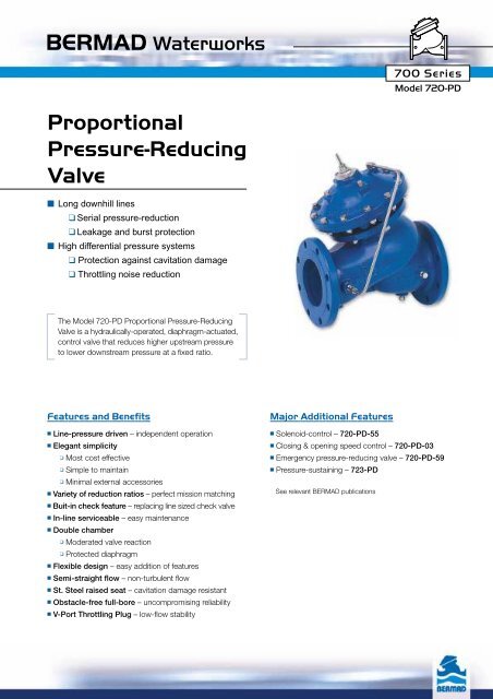
BERMAD Waterworks700 SeriesModel 720-PD<strong>Proportional</strong><strong>Pressure</strong>-<strong>Reducing</strong><strong>Valve</strong>■ Long downhill lines❑ Serial pressure-reduction❑ Leakage and burst protection■ High differential pressure systems❑ Protection against cavitation damage❑ Throttling noise reductionThe Model 720-PD <strong>Proportional</strong> <strong>Pressure</strong>-<strong>Reducing</strong><strong>Valve</strong> is a hydraulically-operated, diaphragm-actuated,control valve that reduces higher upstream pressureto lower downstream pressure at a fixed ratio.Features and Benefits■ Line-pressure driven – independent operation■ Elegant simplicity❑ Most cost effective❑ Simple to maintain❑ Minimal external accessories■ Variety of reduction ratios – perfect mission matching■ Buit-in check feature – replacing line sized check valve■ In-line serviceable – easy maintenance■ Double chamber❑ Moderated valve reaction❑ Protected diaphragm■ Flexible design – easy addition of features■ Semi-straight flow – non-turbulent flow■ St. Steel raised seat – cavitation damage resistant■ Obstacle-free full-bore – un<strong>com</strong>promising reliability■ V-Port Throttling Plug – low-flow stabilityMajor Additional Features■ Solenoid-control – 720-PD-55■ Closing & opening speed control – 720-PD-03■ Emergency pressure-reducing valve – 720-PD-59■ <strong>Pressure</strong>-sustaining – 723-PDSee relevant BERMAD publications
BERMAD WaterworksOperation700 SeriesModel 720-PDThe Model 720-PD is a pilotless, double-chambered, control valve. The downstream pressure is applied as the closing forceon the top-side of both the diaphragm and the seal-disk areas. The upstream pressure is applied as the opening force onthe bottom-side of the seal-disk area.The net force, resulting from the two opposing dynamic forces acting on the actuator's diaphragm, determines the degreeto which the valve is open. The valve seeks the point where these forces are equal. As the ratio of the areas of the seal-diskand the diaphragm is constant, the ratio of the upstream and downstream pressures is constant as well.A rise in downstream pressure causes a momentary increase of the closing force. As a result, the valve throttles closed reducingdownstream pressure according to the constant ratio.Adding a V-Port Throttling Plug modifies valve ratio by increasing the effective diaphragm area.When demand is zero, downstream pressure rises in proportion to the ratio, causing the valve to shut-off.<strong>Valve</strong> Regulates<strong>Valve</strong> Closed (no system demand)Tender SpecificationsThe <strong>Proportional</strong> <strong>Pressure</strong>-<strong>Reducing</strong> <strong>Valve</strong> shall reduce higher upstream pressure to lower downstream pressure at afixed ratio. The valves control loop shall not consists of any pilot.Main <strong>Valve</strong>: The main valve shall be a center-guided, diaphragm-actuated, globe valve of either oblique (Y) or anglepattern design. The body shall have a replaceable, raised, stainless steel seat ring. The valve shall have an unobstructedflow-path, with no stem guides, bearings, or supporting ribs. The body and cover shall be ductile iron. All external bolts,nuts, and studs shall be Duplex® coated. All valve <strong>com</strong>ponents shall be accessible and serviceable without removingthe valve from the pipeline.Actuator: The actuator assembly shall be double-chambered with a sealed inherent separating partition between thelower surface of the diaphragm and the main valve. The entire actuator assembly (seal disk to top cover) shall beremovable from the valve as an integral unit. The stainless steel valve-shaft shall be center-guided by a bearing in theseparating partition. The replaceable radial seal disk shall include a resilient seal and shall be capable of accepting aV-Port Throttling Plug by bolting.Control System: The control system shall consist of a control tube connecting the upper control-chamber to the valveoutlet. All fittings shall be forged brass or stainless steel. The assembled valve shall be hydraulically tested tocustomer requirements.Quality Assurance: The valve manufacturer shall be certified according to the ISO 9001 Quality Assurance Standard.The valve shall be certified as a <strong>com</strong>plete drinking water valve according to NSF, WRAS, and other recognized standards.
BERMAD WaterworksTypical Applications700 SeriesModel 720-PDThere are two major applications for the Model 720-PD <strong>Proportional</strong> <strong>Pressure</strong>-<strong>Reducing</strong> <strong>Valve</strong>:■ Long downhill lines:❏ Systems A1 and A2 prevent the downhill line from exceeding its pressure rating.■ High differential pressure systems:❏ System B reduces cavitation damage and noise level by distributing the load of the high differential pressure.❏ System C illustrates protecting a circulation valve from high differential pressure and resultant severe cavitation .❏ System D shows protecting a level-control valve from high differential pressure.A1DA2CBTypical InstallationsDownhill Serial <strong>Pressure</strong>-<strong>Reducing</strong>A1 A2High Differential <strong>Pressure</strong>-<strong>Reducing</strong> SystemBRelief <strong>Valve</strong>Model 73QRelief <strong>Valve</strong>Model 73QRelief <strong>Valve</strong>Model 73QStrainerModel 70FProprtional-<strong>Pressure</strong><strong>Reducing</strong> <strong>Valve</strong>Model 720-PDStrainerModel 70FProprtional-<strong>Pressure</strong><strong>Reducing</strong><strong>Valve</strong> Model 720-PD <strong>Pressure</strong>-<strong>Reducing</strong><strong>Valve</strong> Model 720High Differential <strong>Pressure</strong> Circulation SystemCPump Control<strong>Valve</strong> Model 740High Differential <strong>Pressure</strong> Level-Control SystemDProprtional<strong>Pressure</strong>-<strong>Reducing</strong><strong>Valve</strong> Model 720-PD<strong>Pressure</strong>-Sustaining <strong>Valve</strong>Model 730(used as circulation valve)Proprtional <strong>Pressure</strong>-<strong>Reducing</strong><strong>Valve</strong> Model 720-PDLevel Control<strong>Valve</strong> Model 750
BERMAD WaterworksTechnical DataDimensions and WeightsSize A, B C L H Weightmm inch mm inch mm inch mm inch mm inch kg lbs405065801001502002503003501 1 /2”22 1 /2”3”4”6”8”10”12”14”3503503503703954304755205455451414141516171921222218018018023027538546058068568577791115182327272052102222503204155006057257338.18.38.79.812.616.319.723.828.528.92392442573053664925847248408669.49.610.112.014.419.423.028.533.134.19.110.6132237751252173703812023294982165276478816840400 16” 645 26 965 38 990 39.0 1108 43.6 846 186545050018”20”645645262696596538381000 39.4 1127 44.41100 43.3 1167 45.9945 2083962 2121Data is for Y-pattern, flanged, PN16 valvesWeight is for PN16 basic valves“C” enables removing the actuator in one unit“L”, ISO standard lengths availableFor more dimensions and weights tables, refer to Engineering sectionMain <strong>Valve</strong><strong>Valve</strong> Patterns: “Y” (globe) & angleSize Range: 1 1 /2–32” (40-800 mm)End Connections (<strong>Pressure</strong> Ratings):Flanged: ISO PN16, PN25(ANSI Class 150, 300)Threaded: BSP or NPTOthers: Available on requestWorking Temperature:Water up to 80°C (180°F)Standard Materials:Body & Actuator: Ductile ironInternals:Stainless steel, bronze & coated steelDiaphragm:NBR (Buna N) Nylon fabric-reinforcedSeals: NBR (Buna N)Coating:Fusion Bonded Epoxy, RAL 5005 (Blue)NSF & WRAS approved or ElectrostaticPolyester Powder, RAL 6017 (Green)How to OrderPlease specify the requested valve in the following sequence: (for more options, refer to Ordering Guide)CHABReduction Ratios Table<strong>Valve</strong> Size1 1 /2- 2 1 /2”40- 65 mm3”80 mm4”100 mm6”150 mm8”200 mm10”250 mm12-14”300-350 mm16-20”400-500 mmStandard ratioL<strong>Pressure</strong> Loss - barFlow Chart1.00.90.80.70.60.50.40.30.2Plug TypeFlat-Disc V-Port3.72.52.62.22.52.02.52.02.42.02.32.02.22.02.22.0700 SeriesModel 720-PDFlow Rate - gpm50 100 500 1,000 5,000 10,0001.5"2"2.5"3"4"6"10987650.1150 500 5,00010 100 1,000 10,000Flow Rate - m 3 /hData is for Y-pattern, flat disc valvesFor more flow charts, refer to Engineering section4.02.72.92.42.82.22.72.22.62.22.52.22.42.22.32.2Optional ratio8"10"12"14"16"18"20"24”32"28"30"432<strong>Pressure</strong> Loss - psi■ The reduction ratios are based on flow velocityof 2.0-3.0 m/sec.■ Reduction ratio may vary at extreme flowvelocity & upstream pressure.■ 24-32” (600-800 mm) reduction ratio: 2.2Control SystemStandard Materials:Accessories: Bronze, brass, stainless steel &NBR (Buna N)Tubing: Copper or stainless steelFittings: Forged brass or stainless steelSectorSizePrimaryFeatureAdditionalFeaturePatternBodyMaterialEndConnectionsCoatingVoltage &PositionTubing& FittingsAdditonalAttributesWW - 6” - 720- PD - -Y-C16EB–CBVIWaterworks 1 1 /2 - 32” <strong>Proportional</strong>Oblique (up to 20”) Y Polyester Green PG<strong>Pressure</strong>-<strong>Reducing</strong> Angle (up to 18”) A Polyester Blue PBGlobe (24-32” only) G Epoxy FB Blue EBUncoatedUCCopper Tubing & Brass FittingsPlastic Tubings & Brass FittingsSt. St. 316 Tubing & FittingsCBPBNNAutomatic Regulation Override 09Solenoid-Controlled 55Electric Override 59Fixed Proportion Standard Ratio PDFixed Proportion Optional RatioPD3Multiple choices permittedDuctile Iron Standard CCast SteelSSt. Steel 316 NNickel Alumin. Bronze UISO-16 16ISO-25 25ANSI-150A5ANSI-300A3JIS-16J6JIS-20J224VAC/50Hz - N.C. 4AC24VAC/50Hz - N.O. 4AO24VDC - N.C. 4DC24VDC - N.O. 4DO24VDC - L.P.4DP220VAC/50-60Hz N.C. 2AC220VAC/50-60Hz N.O. 2AOUse when electric control additionalfeature is selected<strong>Valve</strong> Position IndicatorIV-Port Throttling PlugVElectric Limit-SwitchSSt. St. 316 Internal Trim (Closure & Seat) TSt. St. 316 Actuator Internal Assembly DDelrin BearingRViton Elastomers for Seals & Diaphragm E<strong>Pressure</strong> Gauge 6Multiple choices permittedinfo@bermad.<strong>com</strong> • www.bermad.<strong>com</strong>The information contained in this document is subject to change without notice. BERMAD shall not be liable for any errors contained herein. All rights reserved.© Copyright by BERMAD Control <strong>Valve</strong>s. • PC7WE20-PD 03