T W I N F L E X
T W I N F L E X
T W I N F L E X

Create successful ePaper yourself
Turn your PDF publications into a flip-book with our unique Google optimized e-Paper software.
A joint reliance<br />
T W I N F L E X<br />
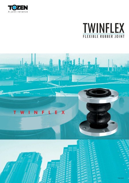
TWINFLEX<br />
FLEXIBLE RUBBER JOINT<br />
TWF-0107
TWINFLEX<br />
TWIN-SPHERE RUBBER JOINT with floating flanges<br />
FEATURES<br />
Resistance High Pressure : The excellent<br />
molding technique, combined with tough<br />
chemical fibers, give TWINFLEX an outstanding<br />
pressure withstandability. It can withstand the<br />
bursting pressure of over 780psi. (55kgf/cm 2 ) and<br />
the max. working pressure of 300psi. (20kgf/cm 2 )<br />
Allow large compression, elongation, and angular<br />
movement.<br />
Fit for suction and delivery (discharge).<br />
Outstanding in absorbing thermal expansion.<br />
TYPICAL APPLICATIONS<br />
1) Pressure piping systems for water and warm<br />
water used in building equipment and general<br />
industrial plants, etc.<br />
2) Pump lines and turbine lines used for power<br />
generation plants, industrial machinery and<br />
universal pump, blowers, etc.<br />
3) Feed-water and drainage lines for waterworks,<br />
sewerage and sanitary piping system, etc.<br />
Others : This connector has wide range of<br />
applications in waste water disposal plants, mines<br />
and chemical plants, etc.<br />
** Please note that TWINFLEX is not applicable<br />
to oils, circulation pumps for pool water, air,<br />
gases and hot water supply line. **<br />
APPLICABLE FLUID<br />
Applicable Fluid : water, warm water, sea water,<br />
weak acids, alkalines, etc.<br />
Other kinds of fluids may be applicable with the<br />
change of the composition or constituents of<br />
rubber. For details, please consult us.<br />
STRUCTURE<br />
Highly effective to eliminate sound and vibration.<br />
Excellent in resisting the effects of heat, water and<br />
weathering, etc.<br />
Other advantages :<br />
1. Neither gasket nor packing is needed.<br />
2. Mass production makes comparatively low prices<br />
possible.<br />
3. Fit for use as both expansion and flexible joint.<br />
4. A good insulator to electricity.<br />
No. Parts Materials<br />
1 Flange<br />
FCD450, SS400<br />
2 Reinforcing Ring Carbon Steel (SWRH)<br />
3 Inner Rubber Synthetic Rubber<br />
4 Outer Rubber Synthetic Rubber<br />
5 Reinforcing Cord Synthetic Fiber<br />
- Standard item employs JIS10K flange. May be<br />
replaced with ANSI, BS, DIN, and other standard<br />
(drilling).<br />
-<br />
Standard rubber is Neoprene. EPDM and other<br />
rubbers are available upon request.<br />
TWF-0107
Dimension and Allowable Movement<br />
Nominal Dia.<br />
(A)<br />
32<br />
40<br />
50<br />
65<br />
80<br />
100<br />
125<br />
150<br />
200<br />
250<br />
300<br />
Ply<br />
4<br />
4<br />
4<br />
4<br />
4<br />
6<br />
6<br />
6<br />
8<br />
8<br />
8<br />
T.M. = Transverse Movement<br />
A.E. = Axial Elongation<br />
A.C. = Axial Compression<br />
A.M. = Angular Movement<br />
Dimension (mm) Allowable Movement (mm) Installation Tolerance (mm)<br />
L OA Od T.M. A.E. A.C. A.M.( o ) T.M. A.E. A.C. A.M.( o )<br />
175<br />
175<br />
175<br />
175<br />
175<br />
225<br />
225<br />
225<br />
325<br />
325<br />
325<br />
Operating Condition<br />
80<br />
80<br />
96<br />
115<br />
125<br />
152<br />
182<br />
212<br />
263<br />
322<br />
370<br />
40<br />
40<br />
50<br />
65<br />
75<br />
100<br />
125<br />
150<br />
200<br />
250<br />
300<br />
20<br />
20<br />
20<br />
20<br />
20<br />
25<br />
25<br />
25<br />
30<br />
30<br />
30<br />
10<br />
10<br />
10<br />
10<br />
10<br />
15<br />
15<br />
15<br />
20<br />
20<br />
20<br />
2<br />
20<br />
20<br />
20<br />
20<br />
20<br />
30<br />
30<br />
30<br />
40<br />
40<br />
40<br />
30<br />
30<br />
30<br />
30<br />
30<br />
30<br />
30<br />
30<br />
30<br />
30<br />
30<br />
8<br />
8<br />
8<br />
8<br />
8<br />
10<br />
10<br />
10<br />
12<br />
12<br />
12<br />
3<br />
3<br />
3<br />
3<br />
3<br />
3<br />
3<br />
3<br />
3<br />
3<br />
3<br />
6<br />
6<br />
6<br />
6<br />
6<br />
6<br />
6<br />
6<br />
6<br />
6<br />
6<br />
10<br />
10<br />
10<br />
10<br />
10<br />
10<br />
10<br />
10<br />
10<br />
10<br />
10<br />
Use the products within the given allowable movements.<br />
Tolerances for installation are included in the allowable movements<br />
(Allowable movements = Tolerances for installation + Operating movements)<br />
Although allowable movements are given, no allowance for elongation is<br />
recommended when installing the joint.<br />
Normal Working Pressure (at normal temp) :<br />
Size 150A & below : Max 20 kgf/cm 2 (300 psi.)<br />
Size 200A & above : Max 16 kgf/cm 2 (240 psi.)<br />
Bursting Pressure : 55 kgf/cm 2 (780 psi.) or<br />
above at normal temp.<br />
Working Temperature : -10 to 70 deg. C.<br />
* For high temp. application, please consult us. *<br />
Control Unit<br />
In case of the following conditions, control unit is recommended to use for protection of connectors.<br />
In case that it is hard to support reaction force (thrust) by pressure during the test<br />
operation or normal operation.<br />
In case that lateral movement is anticipated more than the designed movement.<br />
In case that the connectors are anticipated to be compressed when installation.<br />
When control units are required to assist with the installation of joint, refer to the below table.<br />
Max Working<br />
Size<br />
Pressure 32-100A 125A 150-300A<br />
10 kgf/cm2 16, 20 kgf/cm2 No No Yes<br />
No Yes Yes<br />
Control units for Twinflex can be either back-plate type or integrated type. Next is the illustration of Twinflex<br />
Integrated Type. For back-plate type, please consult us.<br />
TWF-0107
Twinflex Integrated Type<br />
1.<br />
2.<br />
3.<br />
4.<br />
Structure<br />
Dimension (mm)<br />
Nominal Dia.<br />
(A)<br />
32<br />
40<br />
50<br />
65<br />
80<br />
100<br />
125<br />
150<br />
200<br />
250<br />
300<br />
Notes<br />
L OA Od<br />
175<br />
175<br />
175<br />
175<br />
175<br />
225<br />
225<br />
225<br />
325<br />
325<br />
325<br />
80<br />
80<br />
96<br />
115<br />
125<br />
152<br />
182<br />
212<br />
263<br />
322<br />
370<br />
40<br />
40<br />
50<br />
65<br />
75<br />
100<br />
125<br />
150<br />
200<br />
250<br />
300<br />
Information in the above table is for single displacement<br />
only. In case of complex displacement, follow the<br />
below expression.<br />
C.EL(C)=A.EL(C)x{1-(A.T.M.-T.M.xA.A.M.-A.M.)}<br />
A.T.M. A.A.M.<br />
C.EL(C) = Correct Elongation (Compression)<br />
T.M. = Transverse Movement<br />
A.EL(C) = Allowable Elongation (Compression)<br />
A.A.M. = Allowable Angular Movement<br />
A.T.M. = Allowable Transverse Movement<br />
Install the joint according to the above given allowable<br />
dimensions.<br />
Do not install joints at full limits of all allowable<br />
movements simultaneously.<br />
Always check suitability of the operating conditions<br />
when installation of the joint.<br />
OPTIONAL<br />
Ls<br />
320<br />
320<br />
320<br />
320<br />
320<br />
380<br />
380<br />
380<br />
480<br />
480<br />
480<br />
5.<br />
6.<br />
7.<br />
8.<br />
9.<br />
10.<br />
No. Parts Materials<br />
1<br />
2<br />
3<br />
4<br />
5<br />
6<br />
7<br />
Flange<br />
Reinforcing Ring<br />
Inner Rubber<br />
Outer Rubber<br />
Reinforcing Cord<br />
Bolt, Nut, Washer<br />
Bushing<br />
FCD450<br />
Carbon Steel (SWRH)<br />
Synthetic Rubber<br />
Synthetic Rubber<br />
Synthetic Fiber<br />
Mild Steel<br />
Hard Rubber<br />
- Standard item employs ANSI150 and JIS10K flanges.<br />
- Standard rubber is Neoprene. EPDM and other<br />
rubbers are available upon request.<br />
ANSI150LB JIS10K<br />
m-OQ (Md) Z m-OQ (Md) Z<br />
2-23 (M20) 247 2-23 (M20) 255<br />
2-23 (M20) 257 2-23 (M20) 260<br />
2-23 (M20) 262 2-23 (M20) 295<br />
2-23 (M20) 308 2-23 (M20) 315<br />
2-23 (M20) 321 2-23 (M20) 325<br />
2-23 (M20) 359 2-23 (M20) 350<br />
2-23 (M20) 384 3-23 (M20) 390<br />
2-23 (M20) 419 3-23 (M20) 420<br />
2-23 (M20) 483 4-23 (M20) 470<br />
4-23 (M20) 546 4-23 (M20) 540<br />
4-23 (M20) 623 4-23 (M20) 585<br />
- Please follow ANSI or JIS standard for OD, n-OH, and OC.<br />
- For other dimensions, allowable movements, and operating conditions, please refer to the previous table and<br />
graph.<br />
Before installation of the joint, check any cracks on<br />
rubber body surface, especially after a long period<br />
storage.<br />
In case of the joint movements, pay attention for rubber<br />
body not to be damaged by external objects (especially<br />
those with sharp edge).<br />
Keep joints away from heat when installation. Cover the<br />
joint with protection sheet to free from any harm of<br />
sparks resulted from welding, prearcing and grinding<br />
near the spot of installation.<br />
Avoid direct exposure to sunlight for outdoor piping to<br />
prevent aging and deterioration of rubber.<br />
If oil, fat, organic solvent (like thinner, toluene), acid or<br />
alkali are adhered, wipe them off quickly.<br />
To avoid elongation of the joint by reaction force resulted<br />
from water pressure, fix pipes before and after the joint.<br />
3 TWF-0107
TOZEN (THAILAND) CO., LTD.<br />
3388/62 18TH FLOOR, SIRINRAT BLDG.,<br />
RAMA IV RD., BANGKOK 10110 THAILAND<br />
TEL : (66) 0-2367-5721-8<br />
FAX : (66) 0-2367-5729, 0-2367-5066<br />
URL : www.tozen.co.th<br />
A joint reliance<br />
TOZEN SANGYO CO., LTD.<br />
8-4, ASAHI YOSHIKAWA<br />
SAITAMA 342-008 JAPAN<br />
TEL : 048-993-1030<br />
FAX : 048-993-1038<br />
TWF-0107