
Create successful ePaper yourself
Turn your PDF publications into a flip-book with our unique Google optimized e-Paper software.
<strong>SWITCH</strong>-<strong>4X2</strong>4 Input switch with 2 simultanousoutputsOperation Manual<strong>SWITCH</strong>-<strong>4X2</strong>
DisclaimersThe information in this manual has been carefully checked andis believed to be accurate. SPATZ assumes no responsibility for anyinfringements of patents or other rights of third parties which mayresult from its use.SPATZ assumes no responsibility for any inaccuracies that may becontained in this document. SPATZ also makesno commitment to update or to keep current the informationcontained in this document.SPATZ reserves the right to make improvements to thisdocument and/or product at any time and without notice.Copyright NoticeNo part of this document may be reproduced, transmitted,transcribed, stored in a retrieval system, or any of its part translatedinto any language or computer file, in any form or by any means- electronic, mechanical, magnetic, optical, chemical, manual,or otherwise - without express written permission and consent fromSPATZ.© Copyright 2011 by SPATZ. All Rights Reserved. Version 1.0January 2011Trademark AcknowledgmentsAll products or service names mentioned in this document may betrademarks of the companies with which they are associated.
Safety PrecautionsPlease read all instructions before attempting to unpack or install oroperate this equipment, and before connecting the power supply.Please keep the following in mind as you unpack and install thisequipment:‣ Always follow basic safety precautions to reduce the risk offire, electrical shock and injury to persons.‣ To prevent fire or shock hazard, do not expose the unit to rain,moisture or install this product near water.‣ Never spill liquid of any kind on or into this product.‣ Never push an object of any kind into this product throughmodule openings or empty slots, as you may damage parts.‣ Do not attach the power supply cabling to building surfaces.‣ Do not allow anything to rest on the power cabling or allow it tobe abused by persons walking on it.‣ To protect the equipment from overheating, do not block theslots and openings in the module housing that provide ventilation.Revision HistoryVersion No Date Summary of ChangeRDV1 20110103 Preliminary Release
Table of Contents1. Introduction.................................................................................. 12. Applications ................................................................................. 13. Package Contents ...................................................................... 14. System Requirements.................................................................. 15. Features ........................................................................................ 26. Specifications .............................................................................. 27. Operation Controls and Functions............................................. 37.1 Front Panel...................................................................... 37.2 Rear Panel ...................................................................... 48. Remote Control............................................................................ 59. RS-232 Protocol ............................................................................ 59.1 Pin Definition ................................................................... 59.2 Command ...................................................................... 510. Connection and Installation ........................................................ 6
1. IntroductionThis is a high performance four input & two outputs switcher.The output ports support Audio Return Channel (ARC) and HDMI EthernetChannel (HEC) according to HDMI v1.4 specification. The <strong>SWITCH</strong>-<strong>4X2</strong> providesa S/PDIF link from the sink to feed an AV receiver to get digital audio from thesink decoder. The most typical application for this is a TV with built in Satellitereceiver that decodes digital audio and forwards the SPDIF signal through theHDMI cable to the <strong>SWITCH</strong>-<strong>4X2</strong> instead of running an additional SPDIFconnection wire.Another HDMI 1.4 feature is the HEC that adds a connection to the HDMIlink that is capable of carrying the same data as a full duplex, 100MbpsEthernet connection. Connection a Fast speed HDMI cable with Ethernet allowsconvenient integration of Digital Televisions (DTVs) into the end user’s homenetwork system. Simply connect the network cable to the <strong>SWITCH</strong>-<strong>4X2</strong> and makeyour TV part of the IP network through the HDMI cable.2. Applications• Simultaneously display one HDMI source on 2 TVs• Professional audio display• Showroom display• Education demo• Commercial usage3. Package Contents• 4 x 2 HDMI Switcher with HEAC• 5V/2.6A DC power supply adaptor• Operation Manual4. System Requirements• Source equipments with HDMI output connector(s)• Displays TV/monitor with HDMI input connector(s)• Two output ports can be connect to the Ethernet Channel (HEC) of DigitalTelevisions (DTVs) from end user’s home network system and Audio ReturnChannel (ARC) can output to the AVR to get true audio from the sink.1
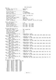
5. Features• Automatic input selection for active source• Both outputs ports support Ethernet Channel (HEC) and Audio ReturnChannel (ARC) according to HDMI v1.4 specification• HDMI 1.4 support:√ Audio Return Channel (ARC)√ 3D√ CEC 1.4√ HDMI Ethernet Channel (HEC), enabling high-speed, bi-directionalnetworking at up to 100Mb/sec• HDCP repeater support• Deep Color support 36/30/24-bit, 1080p@60Hz• EDID fowarding selectable from Standard or Learned from Output 1• Audio support:√√√HDMI 1.4 compatible audio interfaceDolby TrueHDDTS-HD Master Audio6. SpecificationsFrequency Bandwidth 2.25Gbps (single link)Input Ports4x HDMI (Female type)Output Ports2 x HDMI (Female type)2 x Ethernet2 x ARCOutput Resolution480i ~1080p 50/60, 1080p24, VGA~UXGAESD ProtectionHuman Body model: ±8kV (air-gap discharge)± 4kV (contact discharge)Dimensions (mm)(W) x (D) x (H)Weight(g)Chassis MaterialMetalSilkscreen ColorBlackOperating Temperature 0°C ~ 40°C/ 32°F ~104°FStorage Temperature -20°C ~ 60°C/ -4°F ~140°FRelative Humidity20~90% RH (non-condensing)Power Consumption 4.1W2
7. Operation Controls and FunctionsThe following sections describe the hardware components of the unit.7.1 Front Panel1. IR Remote Control Sensor.2. Audio/3D content indicator: The system will automatically detectincoming audio/video signal and the Green LEDs will illuminateaccordingly.3. Input selection: Press input button to select input source, the Blue LED willilluminate accordingly.4. EDID selection: This EDID control button is determining if the <strong>SWITCH</strong>-<strong>4X2</strong> isforwarding the EDID from the display attached to output 1 or use thepreprogrammed EDID. The STD or TV Green LED will illuminateaccordingly. When press EDID button longer then 3 seconds, the RED LEDwill illuminate which means the EDID has been locked to STD or TV EDID asselected previously.5. Power LED Indicator: The LED will illuminate when the power isconnected.3
7.2 Rear Panel1. RS-232: This slot is for RS-232 control signal and for service only.2. The Audio return and Ehternet connectors are part of the new HDMI 1.4features. Both outputs have their own individual audio return and Ethernetchannel. To make these outputs work the TV connected to the HDMI OUT 1and 2 have to support HDMI 1.4 and the cable must be of the Fast Speedwith Ethernet type.Typically the digital audio outputs are used to feed an AV receiver that islocated at the <strong>SWITCH</strong>-<strong>4X2</strong> location receiving the decoded audio signalfrom the TV through the HDMI cable. No additional audio return wire isnecessary.The Ethernet port serves a similar purpose, you may connect your IPconnection to the <strong>SWITCH</strong>-<strong>4X2</strong> and supply a network connection throughthe HDMI cable to your TVs.One HDMI cable can carry HD Video to your TV, receive the decodedaudio and pass IP network signals in both directions !3. HDMI input 1~4: Connect these to HDMI or DVI source equipment suchas DVD player or set-top-box.4. Power: Plug the DC 5V power supply into the s<strong>SWITCH</strong>-<strong>4X2</strong> andconnect the adaptor to AC wall outlet.4
8. Remote Control1 Power button: Press to switch On the device,press it again to set the device in standby mode.2 1~4: Press the number button to select theinput source.9. RS-232 Protocol9.1 Pin Definition<strong>SWITCH</strong>-<strong>4X2</strong>Remote Control ConsolePIN DefinitionPIN Definition1 NC 1 NC2 Tx 2 Rx3 Rx 3 Tx4 NC ►4 NC5 GND ◄5 GND6 NC 6 NC7 NC 7 NC8 NC 8 NC9 NC 9 NCBaud Rate: 9600bpsData bit: 8bitsParity: NoneStop bit: 1 bitFlow Control: None9.2 CommandCommandActionPOWER 00Power Off (standby)POWER 01Power OnPORT 11 Output Select Input 1PORT 12 Output Select Input 2PORT 13 Output Select Input 3PORT 14 Output Select Input 4PORT 21 Output Select Input 1PORT 22 Output Select Input 2PORT 23 Output Select Input 3PORT 24 Output Select Input 45
10. Connection and Installation