Grohtherm 1000 - GROHE
Grohtherm 1000 - GROHE
Grohtherm 1000 - GROHE

You also want an ePaper? Increase the reach of your titles
YUMPU automatically turns print PDFs into web optimized ePapers that Google loves.
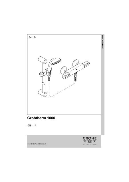
34 154<strong>Grohtherm</strong> <strong>1000</strong><strong>Grohtherm</strong> <strong>1000</strong>D .....1 I .....5 N .....9 GR .....13 TR .....17 BG .....21 RO .....25GB .....2 NL .....6 FIN .....10 CZ .....14 SK .....18 EST .....22 CN .....26F .....3 S .....7 PL .....11 H .....15 SLO .....19 LV .....23 RUS .....27E .....4 DK .....8 UAE .....12 P .....16 HR .....20 LT .....2494.645.131/ÄM 204198/06.07
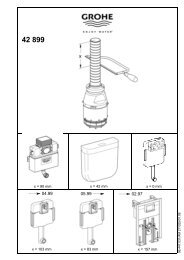
Prod.Nr.122mm2C30mmE34BADCFKL38 °CG HJ5max.min.LPlease pass these instructions on to the end user of the fitting.I
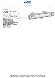
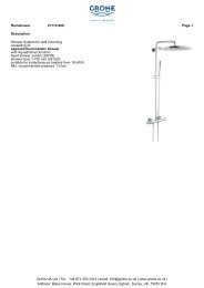
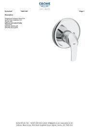
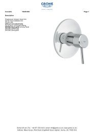
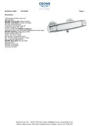
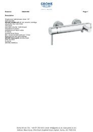
GBApplicationThermostat mixers are designed for hot water supply viapressurised storage heaters and, utilised in this way, providethe best temperature accuracy. With sufficient power output(from 18 kW or 250 kcal/min), electric or gas instantaneousheaters are also suitable.Thermostats cannot be used in conjunction withnon-pressurised storage heaters (displacement water heaters).All thermostats are adjusted in the factory at a flow pressureof 3 bar on both sides.Should temperature deviations occur on account of specialinstallation conditions, the thermostat must be adapted to localconditions (see Adjusting).SpecificationsMinimum flow pressure withoutdownstream resistances0.5 barMinimum flow pressure withdownstream resistances1 barMax. operating pressure10 barRecommended flow pressure1 - 5 barTest pressure16 barFlow rate at 3 bar flow pressureapprox. 26 l/minMax. water temperature at hot water supply 80 °CRecommended max. flow temperature (energy saving) 60 °CSafety stop 38 °CHot water temperature at supply connection min. 2 °C higherthan mixed water temperatureCold water connectionrightHot water connectionleftMinimum flow rate= 5 l/min MaintenanceIf static pressure exceeds 5 bar, a pressure reducing valve mustbe fitted.InstallationFlush pipes thoroughly.Install S-unions and screw-mount the mixer, see fold-out page I,Fig. [1].Refer to the dimensional drawing on fold-out page I.The projection can be increased by 20mm with an extension,see Replacement Parts, fold-out page II, Prod. no. 07 130.Reversed connection (hot on right - cold on left).Replace thermostatic compact cartridge (P), see Replacementparts, fold-out page II, Prod. no.: 47 175 (1/2”).AdjustingTemperature adjustment, see Figs. [2] and [3].1. Open the shut-off valve and check the temperature of thewater with a thermometer, see Fig. [2].2. Lever out cap (A), see Fig. [3].3. Remove screw (B).4. Detach temperature control handle (C).5. Turn regulating nut (D) until the water temperature hasreached 38 °C.6. Install temperature control handle (C) so that button (E)points towards the front, see Fig. [2].7. Screw in screw (B), see Fig. [3].8. Refit cap (A).Temperature limitationThe safety stop limits the temperature range to 38 °C.The 38 °C limit can be overridden by pressing the button (E).Temperature limit stopIf the temperature limit stop should be 43 °C, use handel ref.No. 47 739 (see fold-out page II.)Adjusting the economy stopVolume adjustment, see fold-out page I, Figs. [4] and [5].• The flow rate is limited by a stop adjusted at the factory. If ahigher flow rate is desired, the stop can be overridden bypressing the button (F), see Fig. [4].To adjust the stop, proceed as follows:1. Close shut-off valve.2. Lever out cap (G).3. Remove screw (H) and detach shut-off handle (J).4. Remove splined adapter (K) and economy stop (L).5. Reinstall economy stop (L) in the desired position. Foradjustment range, see Fig. [5].6. Fit splined adapter (K), see Fig. [4].7. Fit shut-off handle (J) so that the button (F) points towardsthe front.8. Screw in screw (H).9. Refit cap (G).Prevention of frost damageWhen the domestic water system is drained, thermostat mixersmust be drained separately, since non-return valves areinstalled in the hot and cold water connections. For thispurpose, the mixer must be removed from the wall.Inspect and clean all parts, replace if necessary and lubricatewith special valve grease.Shut off the hot and cold water supply.I. Non-return valve (M) or (N), see fold-out page III, Fig. [6].• Remove connection nipple (O) by turning clockwise (lefthandthread) using a 12mm allen key.Install in reverse order.II. Thermostatic compact cartridge (P), see fold-out page III,Fig. [7].• Loosen screw ring (R) using a 34mm tool.• If necessary, lever out thermostatic compact cartridge (P)via recess (P1).• Remove screw ring (R).Install in reverse order.Observe the correct installation position of thethermostatic compact cartridge (P), see detail (P2).Readjustment is necessary after every maintenance operationon the thermostatic compact cartridge (see Adjusting).III. Ceramic headpart (S), see fold-out page III, Fig. [8].Install in reverse order.Replacement Parts, see fold-out page II ( * = specialaccessories).CareFor directions on the care of this fitting, refer to theaccompanying Care Instructions.1
17mm612mm30mmOMN7*19 33234mmPRPP1P28SIII