
You also want an ePaper? Increase the reach of your titles
YUMPU automatically turns print PDFs into web optimized ePapers that Google loves.
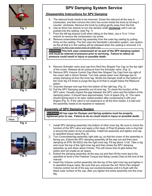
SPV Damping System <strong>Service</strong>Disassembly Instructions for SPV DampingFig. 1SPV CapFig. 25. The rebound knob needs to be removed. Screw the rebound all the way in(clockwise), and then remove the 2mm hex screw inside the knob by turning itcounter- clockwise. Remove the knob by pulling gently away from the fork.6. Use an 8mm hex wrench to turn the damper shaft clockwise until it can bepushed into the casting. (see Fig. 1)7. From the left leg dropout (Left when sitting on the bike), use a 10 or 11mmwrench to remove the compression rod screw.8. Remove crown/steer/inner leg assembly from the outer leg casting by pullingfirmly on the casting. The fork uses the Semibath Lubrication system, use cautionas the oil that is in the casting will be released when the casting is removed, it isbest to do this over some type of catch pan.WARNING This fork uses compressed air as part of the SPV damping systemand must be relieved of pressure prior to servicing. Failure to relieve airpressure could result in injury or possible death.OpenFig. 3Fig. 4Fig. 59. Remove Schrader valve dust cap from Red Hex Shaped Top Cap on the top rightof the crown. Release all air pressure from the Schrader valve. (Fig. 2)10. Remove SPV Volume Control Cap (Red Hex Shaped Top Cap) from top right ofthe crown with a 24mm Socket. Turn fork upside down over drainage pan toempty Damping oil from the inner leg. Stroke the Damper shaft on the bottom ofthe inner leg 3-5 times to purge the leg of oil that is caught below the Reboundpiston.11. Unscrew Damper end cap from the bottom of the right leg. (Fig. 3)12. Pull the SPV Damping assembly out of inner leg. To check the function of theSPV valve: Visually inspect the gap between the SPV valve and the bottom of thedamping piston. It should have approximately 1mm of space (Fig. 4). The valveshould spring back to its open rested position after compressing it with yourfingers (Fig. 5). If the valve is not responsive or all the time closed, it is bad andthe assembly needs to be repaired or replaced.Assembly of SPV Damping SystemWARNING All top caps for Damper and Spring systems must be properlytightened prior to use. Failure to do so could result in injury or possible death.1. Install SPV damping assembly into bottom of other inner leg. Be sure to check thefunction of the SPV valve and apply a thin layer of Prep M grease onto o-ring thatis around the piston at top of assembly. Install the assembly and tighten end capto specified torque value.(Fig. 6)2. Turn Crown/steer/leg assembly right side up, so that the crown of the assembly isfacing you. Extend the SPV damping assembly all the way out and then pourdamping oil (P/N: 85-0023) into the right inner leg. Fill leg about ¼ full. Take a ragand cover the top of the right inner leg and then stroke the SPV dampingassembly up and down about 5 times. This will insure that oil gets below thepiston and not create an air space.3. Extend the damping assembly all the way out and then fill the inner leg to thespecified oil level in the Fastener Torque and Setup Levels Chart at the end of themanual4. Insert the Volume control assembly into the top of the right inner leg and tighten itto specified torque value. Be sure that you unscrew the red 16mm Hex shapedVolume control nut all of the way out counterclockwise until it is flush with theblack outer surface of the cap, after you tighten the entire assembly into the innerleg.