
Create successful ePaper yourself
Turn your PDF publications into a flip-book with our unique Google optimized e-Paper software.
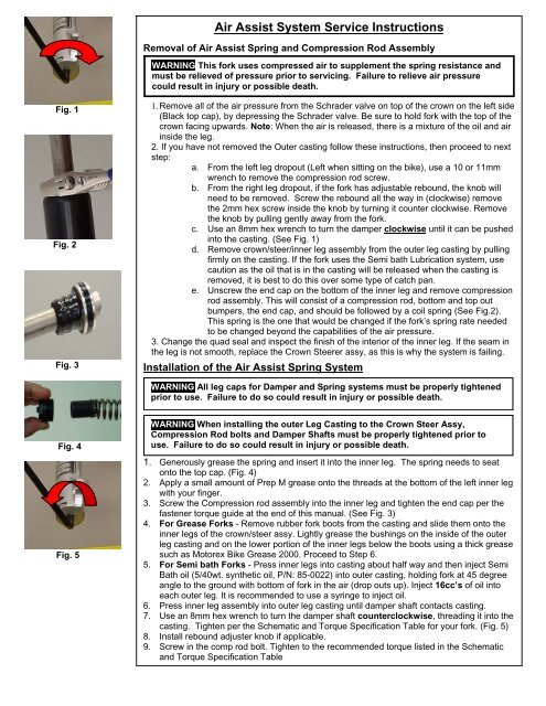
Air Assist System <strong>Service</strong> InstructionsRemoval of Air Assist Spring and Compression Rod AssemblyWARNING This fork uses compressed air to supplement the spring resistance andmust be relieved of pressure prior to servicing. Failure to relieve air pressurecould result in injury or possible death.Fig. 1Fig. 2Fig. 31. Remove all of the air pressure from the Schrader valve on top of the crown on the left side(Black top cap), by depressing the Schrader valve. Be sure to hold fork with the top of thecrown facing upwards. Note: When the air is released, there is a mixture of the oil and airinside the leg.2. If you have not removed the Outer casting follow these instructions, then proceed to nextstep:a. From the left leg dropout (Left when sitting on the bike), use a 10 or 11mmwrench to remove the compression rod screw.b. From the right leg dropout, if the fork has adjustable rebound, the knob willneed to be removed. Screw the rebound all the way in (clockwise) removethe 2mm hex screw inside the knob by turning it counter clockwise. Removethe knob by pulling gently away from the fork.c. Use an 8mm hex wrench to turn the damper clockwise until it can be pushedinto the casting. (See Fig. 1)d. Remove crown/steer/inner leg assembly from the outer leg casting by pullingfirmly on the casting. If the fork uses the Semi bath Lubrication system, usecaution as the oil that is in the casting will be released when the casting isremoved, it is best to do this over some type of catch pan.e. Unscrew the end cap on the bottom of the inner leg and remove compressionrod assembly. This will consist of a compression rod, bottom and top outbumpers, the end cap, and should be followed by a coil spring (See Fig.2).This spring is the one that would be changed if the fork’s spring rate neededto be changed beyond the capabilities of the air pressure.3. Change the quad seal and inspect the finish of the interior of the inner leg. If the seam inthe leg is not smooth, replace the Crown Steerer assy, as this is why the system is failing.Installation of the Air Assist Spring SystemWARNING All leg caps for Damper and Spring systems must be properly tightenedprior to use. Failure to do so could result in injury or possible death.Fig. 4Fig. 5WARNING When installing the outer Leg Casting to the Crown Steer Assy,Compression Rod bolts and Damper Shafts must be properly tightened prior touse. Failure to do so could result in injury or possible death.1. Generously grease the spring and insert it into the inner leg. The spring needs to seatonto the top cap. (Fig. 4)2. Apply a small amount of Prep M grease onto the threads at the bottom of the left inner legwith your finger.3. Screw the Compression rod assembly into the inner leg and tighten the end cap per thefastener torque guide at the end of this manual. (See Fig. 3)4. For Grease <strong>Fork</strong>s - Remove rubber fork boots from the casting and slide them onto theinner legs of the crown/steer assy. Lightly grease the bushings on the inside of the outerleg casting and on the lower portion of the inner legs below the boots using a thick greasesuch as Motorex Bike Grease 2000. Proceed to Step 6.5. For Semi bath <strong>Fork</strong>s - Press inner legs into casting about half way and then inject SemiBath oil (5/40wt. synthetic oil, P/N: 85-0022) into outer casting, holding fork at 45 degreeangle to the ground with bottom of fork in the air (drop outs up). Inject 16cc’s of oil intoeach outer leg. It is recommended to use a syringe to inject oil.6. Press inner leg assembly into outer leg casting until damper shaft contacts casting.7. Use an 8mm hex wrench to turn the damper shaft counterclockwise, threading it into thecasting. Tighten per the Schematic and Torque Specification Table for your fork. (Fig. 5)8. Install rebound adjuster knob if applicable.9. Screw in the comp rod bolt. Tighten to the recommended torque listed in the Schematicand Torque Specification Table