
Create successful ePaper yourself
Turn your PDF publications into a flip-book with our unique Google optimized e-Paper software.
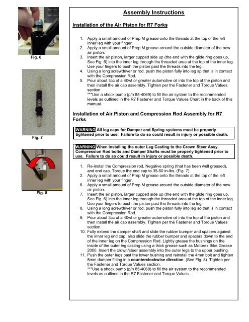
Assembly InstructionsInstallation of the Air Piston for R7 <strong>Fork</strong>sFig. 61. Apply a small amount of Prep M grease onto the threads at the top of the leftinner leg with your finger.2. Apply a small amount of Prep M grease around the outside diameter of the newair piston.3. Insert the air piston, larger cupped side up (the end with the glide ring goes up,See Fig. 6) into the inner leg through the threaded area at the top of the inner leg.Use your fingers to push the piston past the threads into the leg.4. Using a long screwdriver or rod, push the piston fully into leg sp that is in contactwith the Compression Rod.5. Pour about 3cc of a 40wt or greater automotive oil into the top of the piston andthen install the air cap assembly. Tighten per the Fastener and Torque Valuessection***Use a shock pump (p/n 85-4069) to fill the air system to the recommendedlevels as outlined in the R7 Fastener and Torque Values Chart in the back of thismanual.Installation of Air Piston and Compression Rod Assembly for R7<strong>Fork</strong>sFig. 7WARNING All leg caps for Damper and Spring systems must be properlytightened prior to use. Failure to do so could result in injury or possible death.WARNING When installing the outer Leg Casting to the Crown Steer Assy,Compression Rod bolts and Damper Shafts must be properly tightened prior touse. Failure to do so could result in injury or possible death.Fig. 81. Re-install the Compression rod, Negative spring (that has been well greased),and end cap. Torque the end cap to 35-50 in-lbs. (Fig. 7)2. Apply a small amount of Prep M grease onto the threads at the top of the leftinner leg with your finger.6. Apply a small amount of Prep M grease around the outside diameter of the newair piston.7. Insert the air piston, larger cupped side up (the end with the glide ring goes up,See Fig. 6) into the inner leg through the threaded area at the top of the inner leg.Use your fingers to push the piston past the threads into the leg.8. Using a long screwdriver or rod, push the piston fully into leg so that is in contactwith the Compression Rod.9. Pour about 3cc of a 40wt or greater automotive oil into the top of the piston andthen install the air cap assembly. Tighten per the Fastener and Torque Valuessection.10. Fully extend the damper shaft and slide the rubber bumper and spacers againstthe inner leg end cap, also slide the rubber bumper and spacers down to the endof the inner leg on the Compression Rod. Lightly grease the bushings on theinside of the outer leg casting using a thick grease such as Motorex Bike Grease2000. Insert the crown/steer assembly into the outer legs to the upper bushing.11. Push the outer legs past the lower bushing and reinstall the 4mm bolt and tighten8mm damper fitting in a counterclockwise direction. (See Fig. 8) Tighten perthe Fastener and Torque Values section.***Use a shock pump (p/n 85-4069) to fill the air system to the recommendedlevels as outlined in the R7 Fastener and Torque Values.