UEi M75A Analog Multimeter Manual PDF - Instrumart
UEi M75A Analog Multimeter Manual PDF - Instrumart
UEi M75A Analog Multimeter Manual PDF - Instrumart

Create successful ePaper yourself
Turn your PDF publications into a flip-book with our unique Google optimized e-Paper software.
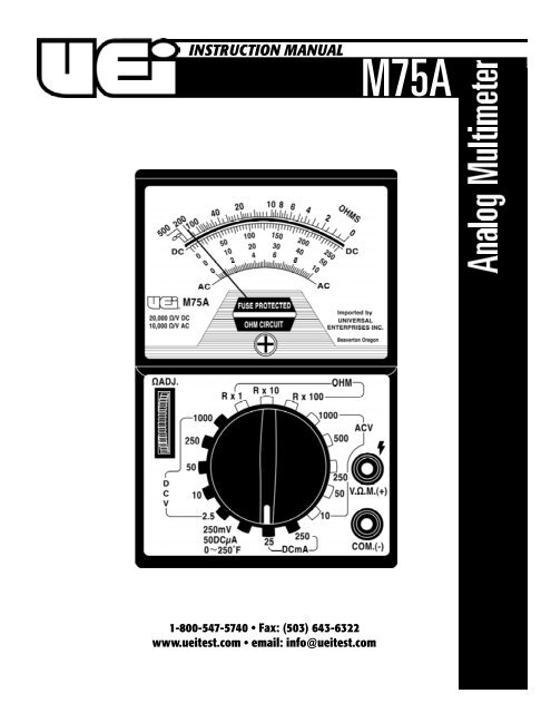
INSTRUCTION MANUAL<strong>M75A</strong>1-800-547-5740 • Fax: (503) 643-6322www.ueitest.com • email: info@ueitest.com
IntroductionThe <strong>M75A</strong> has the features you need for testing electrical and HVAC/Rsystems. Its voltage ranges are scaled to keep typical readings in themiddle of the scale for increased accuracy and resolution. It alsoincludes a low ohm scale to test critical connections as well asmicroamps and millivolts functions to verify heat anticipator and flamesafeguard circuits.Features include• 17 ranges• 1000 Volts AC and DC• Resistance 50 kilohm• DC micro/milli amps• DC millivolt scale allows use of adapters• Color-coded and mirrored scale plateSafety NotesBefore using this meter, read all safety information carefully. Inthis manual the word "WARNING" is used to indicate conditionsor actions that may pose physical hazards to the user. The word"CAUTION" is used to indicate conditions or actions that maydamage this instrument.C o n t rols and Indicators33. Mechanical Zero Adjust: Is a plastic screw located on themeter face just beneath the green “FUSE PROTECTED OHMCIRCUIT” label. This adjustment is used to set the pointer to thezero index mark at the left side of the scale plate.4. Input Jacks:COM (-): The black test lead is used to connect this jack to thenegative, or common, side of the circuit under test.VΩM (+): This adjustment is used to set the pointer to the zeroindex mark at the left side of the scale plate.Operating InstructionsWARNING!Observe all safety precautions when measuring higher voltages.Turn off power to the circuit under test. Set the <strong>M75A</strong> controls,connect the test leads to the meter and then to the circuit undertest. Reapply power. If the pointer does not move, make sure thatthe protective fuse is not open.Color CodingThe meter scale plate and front panel are color coded. The DC Voltagesand DC Current meter scale and “SELECTOR” switch positions are inblack. The OHMS meter scale and “SELECTOR” switch positions are ingreen. The AC Voltage meter scales and “SELECTOR” switch positionsare in red.To provide an uncrowded easy-to-read meter scale plate a single meterscale may be used for more than one position of the “SELECTOR”switch. For example, the meter scale numerals 0 - 50 are used for thefollowing positions of the “SELECTOR” switch: 50V DC, 50µA DC, 50VAC and 500V AC. To take a reading at any of the above “SELECTOR”switch positions the 0 - 50 scale numerals are either read directly ordivided by 10. Example: (1) If the “SELECTOR” switch is set on 50V DCthen read the numerals directly. (2) If the “SELECTOR” switch is set on500V AC then multiply the 0 - 50 numerals by 10 (this will give a scaleof 0 - 500).214Measuring DC VoltageSet the “SELECTOR” switch to the appropriate range. Always start withthe 1000V DC position if unsure of the magnitude of voltage present.Connect the black test lead to the “COM” jack and to the negative sideof the circuit under test. Connect the red test lead to the “+VΩM” jackand to the positive side of the circuit under test. Read the voltage on theblack meter scale corresponding to the “SELECTOR” switch setting.Note: the 250mV DC and the 50µA DC readings are taken at the sameposition of the “SELECTOR” switch.1. Selector Switch: Is used to select the circuit function and range.it is good practice to start with the highest range setting of theselector switch for a particular function if the magnitude of thefunction is unknown.2. ΩADJ: Is used only on the OHMS function. The purpose of thiscontrol is to calibrate the <strong>M75A</strong> on the particular range selected(Rx1, Rx10, etc.)<strong>M75A</strong>-MAN P. 1
Measuring DC CurrentSet the “SELECTOR” switch to the appropriate range. Always startwith the 250 mA DC position if unsure of the magnitude of currentpresent. When taking current measurements the meter must beconnected in SERIES with the circuit, or circuit element, under test.Break the connection at which current is to be measured. Place the<strong>M75A</strong> in series with the circuit be connecting the black test lead to the“COM” jack and to the lower voltage side of the circuit. Connect thered test lead to the “+VΩM“ jack and to the higher voltage side of thecircuit. Read the current on the black meter scale corresponding to the“SELECTOR” switch. The symbol “µ” is the standard symbol for theword “MICRO”. Hence, 50 µA DC = 50 DC microamp.Measuring ResistanceWARNING!Remove all power to the circuit under test when making resistancemeasurements. If any voltage is present in the test circuit an erroneousreading will result and the 1/4A fuse may open.Set the “SELECTOR” switch to the appropriate range. Connect one testlead to the “COM” jack and the other test lead to the “+VΩM“ jack.Touch the free ends of the test leads together. The pointer will swing tothe right hand side of thee scale. Adjust the “Ω ADJ“ control until thepointer is set on the green numeral 0. (Note: If this adjustment cannotbe made refer to the “MAINTENANCE” section). Re-zero the <strong>M75A</strong> eachtime the OHMS setting of the “SELECTOR” switch is changed. To makethe resistance measurement, connect the free ends of the test leadsacross the element to be measured. The measured resistance valuewill be the green numeral indicated on the OHMS scale times themultiplier on the “SELECTOR” switch. For example, if the pointer ison the numeral 4, and the “SELECTOR” switch is set on Rx 10, theresistance is 40 ohms (4Ω x 10 = 40Ω).Continuity tests are normally made to test a wire, or element, to see if itis unbroken. Because continuity tests involve low values or resistance,the “SELECTOR” switch should be set on the Rx1 position.Testing Diodes / TransistorsA simple check of diode or transistor quality may be made with the<strong>M75A</strong>. Using the same test procedure as for measuring resistance,connect one test lead to one end of the diode and the other end of thediode. Note the resistance reading. Then reverse the test leads andagain note the reading. If the two readings differ by a factor of ten thenthe diode, (or transistor junction) is probably good. If the readings areapproximately the same then the diode is shorted. If a reading cannotbe obtained in either direction, the diode is probably open. Transistorjunction measurements should be taken between the base and emitterleads, or between the base and collector leads.Measuring AC VoltageSet the “SELECTOR” switch to the appropriate range. Always startwith the 1000V AC position if unsure of the magnitude of voltagepresent. Connect the test leads to the “COM” jack and the “VΩM“jack and to the circuit under test. Read the voltage on the red meterscale corresponding to the “SELECTOR” switch setting.Periodic ServiceM a i n t e n a n c eWARNING!Repair and service of this instrument is to be performed by qualifiedpersonnel only. Improper repair or service could result in physicaldegradation of the meter. This could alter the protection fromelectrical shock and personal injury this meter provides to theoperator. Perform only those maintenance tasks that you arequalified to do.These guidelines will help you attain long and reliable service fromyour meter:• Calibrate your meter annually to ensure it meets originalperformance specifications• Keep your meter dry. If it gets wet, wipe dry immediately.Liquids can degrade electronic circuits• Whenever practical, keep the meter away from dust anddirt that can cause premature wear• Although your meter is built to withstand the rigors of dailyuse, it can be damaged by severe impacts. Use reasonablecaution when using and storing the meterCleaningPeriodically clean your meter’s case using a damp cloth. DO NOT useabrasive, flammable liquids, cleaning solvents, or strong detergents asthey may damage the finish, impair safety, or affect the reliability of thestructural components.Battery ReplacementThe purpose of the batteries is to supply power to the circuit under testwhile making resistance measurements. Eventually the batteries will ageto the point where it will not be possible to zero the meter with the“ΩADJ” control. When this happens the batteries should be replaced.The two 1.5V size “AA” batteries are used only on the Rx1, Rx10, andRx100 setting of the “SELECTOR” switch and should be replaced as apair. Observe the proper battery polarity when replacing batteries. It isrecommended that all batteries be removed if the <strong>M75A</strong> is not to beused for a long period of time. Remove the single screw in the rear ofthe case for access to the batteries.FusesThe 1/4A, 2.0 ohm, fuse is in series with the “+VΩM“ input jack. If thisfuse is open none of the circuit functions will work. When replacing thefuse be sure to replace it with a fuse of the same current rating andinternal resistance. The use of a fuse with a different internal resistancemay cause the accuracy of the OHMS scale to be off. Remove the singlescrew in the rear of the case for access to the fuse.Mechanical Zero AdjustmentThe pointer is set to register 0 at the left hand edge of the scale whenthere is no input to the M75 and it is laying face up on a flat surface. Ifthe pointer does not register 0, it may be reset to that position by carefullyadjusting the plastic screw in the meter face, just below the green“FUSE PROTECTED OHMS CIRCUIT” label.<strong>M75A</strong>-MAN P. 2
S p e c i f i c a t i o n sRangesDC Millivolts0 - 250 mVDC Volts0 - 2.5, 10, 50, 250, 1000 VDC Microamps 0 - 50 µADC Milliamps0 - 25, 250 mAOHMS0 - 500Ω, 5K, 50KAC Volts0 - 10, 50, 250, 500, 1000 VTemperature0 - 250˚FAccuracyDC±3% of full scaleOHMS±3% of scale lengthAC±4% of full scaleTemperature±2 divisionsGeneralInput Impedance 20KΩ / V DC, 10KΩ / V ACBatteriesTwo 1.5V, size AA (NEDA #15D) batteriesFuse1/4A (2.0 ohm internal resistance) 3AG seriesNote: To maintain calibration accuracy and instrumentprotection, replacement fuse must be of the propercurrent and resistance value.Standard and Optional AccessoriesStandardTest leads (set) . . . . . . . . . . . . . . . . . . . . . . . . . . . . . . . . . . . . . . .ATL3Test leads, rubber . . . . . . . . . . . . . . . . . . . . . . . . . . . . . . . . . . . . .ATL25Alligator clip adapters . . . . . . . . . . . . . . . . . . . . . . . . . . . . . . . . . .AACFuse 1/4A, 2Ω . . . . . . . . . . . . . . . . . . . . . . . . . . . . . . . . . . . . . . . .AF2Battery 1.5V, size AA . . . . . . . . . . . . . . . . . . . . . . . . . . . . . . . . . . .AB1OptionalTemperature adapter . . . . . . . . . . . . . . . . . . . . . . . . . . . . . . . . . .TA2K<strong>M75A</strong>-MAN P. 3
<strong>M75A</strong><strong>Analog</strong> <strong>Multimeter</strong>Limited WarrantyThe <strong>M75A</strong> is warranted to be free from defects in materials and workmanship for a period ofthree years from the date of purchase. If within the warra n ty period your instrument shouldbecome inoperative from such defects, the unit will be repaired or replaced at <strong>UEi</strong>’s option.This warra n ty covers normal use and does not cover damage which occurs in shipment orfailure which results from alteration, tampering, accident, misuse, abuse, neglect or impropermaintenance. Batteries and consequential damage resulting from failed batteries are notcovered by warra n ty.Any implied warranties, including but not limited to implied warranties of merchantabilityand fitness for a particular purpose, are limited to the express warranty. <strong>UEi</strong> shall not beliable for loss of use of the instrument or other incidental or consequential damages,expenses, or economic loss, or for any claim or claims for such damage, expenses oreconomic loss. A purchase receipt or other proof of original purchase date will be requiredbefore warra n ty repairs will be rendered. Instruments out of warra n ty will be repaired (whenr e p a i rable) for a service charge. Return the unit postage paid and insured to:1-800-547-5740 • FAX: (503) 643-6322www.ueitest.com • Email: info@ueitest.comThis warranty gives you specific legal rights. You may also have other rights which vary fromstate to state.PLEASERECYCLECopyright © 2007 <strong>UEi</strong> <strong>M75A</strong>-MAN 1/07