- Page 1: SSC - 419SUPPLEMENTAL COMMERCIALDES
- Page 4 and 5: CONVERSION FACTORS(Approximate conv
- Page 6: able to be applied to a naval ship.
- Page 9 and 10: Whipping—Vibration of the hull gi
- Page 11 and 12: Table of ContentsSection Title Page
- Page 13 and 14: Section Title Page8.2 Commercial Sh
- Page 15 and 16: Figure Title Page5.4 Design Code S/
- Page 17 and 18: 1.2 Commercial Approaches and Pract
- Page 19 and 20: Navy have standards for hull girder
- Page 21 and 22: 2. Current Commercial Practicesfor
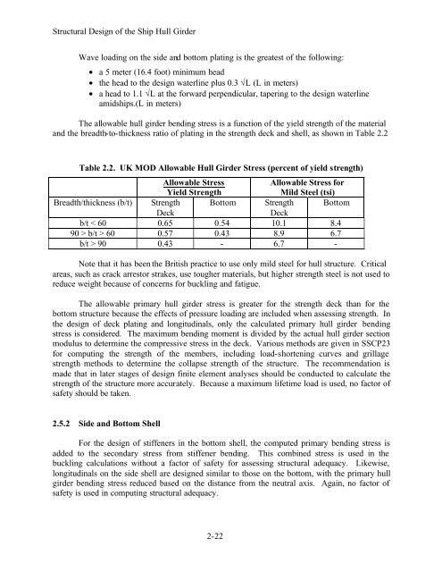
- Page 23 and 24: Structural Design of the Ship Hull
- Page 25 and 26: Structural Design of the Ship Hull
- Page 27 and 28: Structural Design of the Ship Hull
- Page 29 and 30: Structural Design of the Ship Hull
- Page 31 and 32: Structural Design of the Ship Hull
- Page 33 and 34: Structural Design of the Ship Hull
- Page 35 and 36: Structural Design of the Ship Hull
- Page 37 and 38: Structural Design of the Ship Hull
- Page 39 and 40: Structural Design of the Ship Hull
- Page 41: Structural Design of the Ship Hull
- Page 45 and 46: Structural Design of the Ship Hull
- Page 47 and 48: 3. Operational Environments Used in
- Page 49 and 50: Operational Environmentsfrom the U.
- Page 51 and 52: Operational Environmentsships monit
- Page 53 and 54: Operational Environmentsship specif
- Page 55 and 56: Operational Environmentsor North At
- Page 57 and 58: Operational EnvironmentsShip G Clas
- Page 59 and 60: Operational Environmentselement ana
- Page 61 and 62: Ship Lifetime Bending and Torsional
- Page 63 and 64: Ship Lifetime Bending and Torsional
- Page 65 and 66: Ship Lifetime Bending and Torsional
- Page 67 and 68: Ship Lifetime Bending and Torsional
- Page 69 and 70: Ship Lifetime Bending and Torsional
- Page 71 and 72: Ship Lifetime Bending and Torsional
- Page 73 and 74: Ship Lifetime Bending and Torsional
- Page 75 and 76: Fatigue Data for Ship Structural De
- Page 77 and 78: Fatigue Data for Ship Structural De
- Page 79 and 80: Fatigue Data for Ship Structural De
- Page 81 and 82: Fatigue Data for Ship Structural De
- Page 83 and 84: Fatigue Data for Ship Structural De
- Page 85 and 86: Fatigue Data for Ship Structural De
- Page 87 and 88: Fatigue Data for Ship Structural De
- Page 89 and 90: Fatigue Data for Ship Structural De
- Page 91 and 92: Fatigue Data for Ship Structural De
- Page 93 and 94:
Fatigue Data for Ship Structural De
- Page 95 and 96:
Fatigue Data for Ship Structural De
- Page 97 and 98:
Fatigue Data for Ship Structural De
- Page 99 and 100:
Supplemental Commercial Design Guid
- Page 101 and 102:
Supplemental Commercial Design Guid
- Page 103 and 104:
Supplemental Commercial Design Guid
- Page 105 and 106:
Supplemental Commercial Design Guid
- Page 107 and 108:
Supplemental Commercial Design Guid
- Page 109 and 110:
Supplemental Commercial Design Guid
- Page 111 and 112:
Supplemental Commercial Design Guid
- Page 113 and 114:
Supplemental Commercial Design Guid
- Page 115 and 116:
Supplemental Commercial Design Guid
- Page 117 and 118:
Supplemental Commercial Design Guid
- Page 119 and 120:
Supplemental Commercial Design Guid
- Page 121 and 122:
Supplemental Commercial Design Guid
- Page 123 and 124:
Supplemental Commercial Design Guid
- Page 125 and 126:
Supplemental Commercial Design Guid
- Page 127 and 128:
Supplemental Commercial Design Guid
- Page 129 and 130:
Supplemental Commercial Design Guid
- Page 131 and 132:
Supplemental Commercial Design Guid
- Page 133 and 134:
Supplemental Commercial Design Guid
- Page 135 and 136:
Supplemental Commercial Design Guid
- Page 137 and 138:
Supplemental Commercial Design Guid
- Page 139 and 140:
Supplemental Commercial Design Guid
- Page 141 and 142:
Supplemental Commercial Design Guid
- Page 143 and 144:
Supplemental Commercial Design Guid
- Page 145 and 146:
Supplemental Commercial Design Guid
- Page 147 and 148:
Supplemental Commercial Design Guid
- Page 149 and 150:
Supplemental Commercial Design Guid
- Page 151 and 152:
Supplemental Commercial Design Guid
- Page 153 and 154:
Supplemental Commercial Design Guid
- Page 155 and 156:
Supplemental Commercial Design Guid
- Page 157 and 158:
Supplemental Commercial Design Guid
- Page 159 and 160:
Supplemental Commercial Design Guid
- Page 161 and 162:
Supplemental Commercial Design Guid
- Page 164 and 165:
11. Suggested Modifications to the
- Page 166 and 167:
Suggested Modifications to the Safe
- Page 168 and 169:
Suggested Modifications to the Safe
- Page 170 and 171:
Suggested Modifications to the Safe
- Page 172 and 173:
Suggested Modifications to the Safe
- Page 174 and 175:
12. CONCLUSIONSThe ABS SafeHull Pha
- Page 176 and 177:
13. RECOMMENDATIONSThe following re
- Page 178 and 179:
14. REFERENCESAASHTO, Standard Spec
- Page 180 and 181:
ReferencesHeyburn, R. and D. Riker,
- Page 182 and 183:
ReferencesNaval Ships’ Technical
- Page 184 and 185:
ReferencesSNAME, Application of Pro
- Page 186 and 187:
Guide for the Use of Commercial Des
- Page 188 and 189:
Phase A analysis. This guide provid
- Page 190 and 191:
Table 1 Stiffener Library Data File
- Page 192 and 193:
SafeHull, so it is not necessary to
- Page 194 and 195:
Figure 4 General Data for Section D
- Page 196 and 197:
to define the Bilge, Gunwale, or In
- Page 198 and 199:
Figure 6 The Stiffener Properties S
- Page 200 and 201:
Figure 7 2-D Shell Shape Definition
- Page 202 and 203:
produce a screen similar to Figure
- Page 204 and 205:
in sequence. If errors are found in
- Page 206 and 207:
7.2.2.2 Once the SafeHull Phase A h
- Page 208 and 209:
many limitations associated with th
- Page 210 and 211:
App A-1APPENDIX AFATIGUE ANALYSIS S
- Page 212 and 213:
App A-3STF#SafeHullSTF IDTOE ID Dis
- Page 214 and 215:
App A-5Table A.2 SafeHull Phase A F
- Page 216 and 217:
App A-7STF#Table A.3 SafeHull Phase
- Page 218 and 219:
App A-9STF#SafeHullSTF IDTOE ID Dis
- Page 220 and 221:
App A-11CutoutLABELID LOCDist.fromB
- Page 222 and 223:
App B-2STF#SafeHullSTF IDTable B.1
- Page 224 and 225:
App B-4STF#SafeHullSTF IDTOE ID Dis
- Page 226 and 227:
App B-6STF#SafeHullSTF IDTOE ID Dis
- Page 228 and 229:
App B-8STF#SafeHullSTF IDTOE ID Dis
- Page 230 and 231:
App B-10CutoutLABEL ID LOCTable B.2
- Page 232 and 233:
App C-1APPENDIX CFATIGUE ANALYSIS S
- Page 234 and 235:
App C-3STF#SafeHullSTF IDTOE ID Dis
- Page 236 and 237:
App C-5STF#SafeHullSTF IDTOE ID Dis
- Page 238 and 239:
App C-7STF#SafeHullSTF IDTOE ID Dis
- Page 240 and 241:
App C-9CutoutLABELID LOCDist.fromBL
- Page 242 and 243:
App C-11STF#SafeHullSTF IDTOE IDDis
- Page 244 and 245:
App C-13STF#SafeHullSTF IDTOE IDDis
- Page 246 and 247:
App C-15STF#SafeHullSTF IDTOE IDDis
- Page 248 and 249:
App C-17CutoutLABELID LOC Dist.from
- Page 250 and 251:
App D-2Table D.1 SafeHull Phase A F
- Page 252 and 253:
App D-4STF#SafeHullSTF IDTOE IDDist
- Page 254 and 255:
App D-6Table D.2 SafeHull Phase A F
- Page 256 and 257:
App D-8STF#SafeHullSTF IDTOE IDDist
- Page 258 and 259:
App D-10STF#SafeHullSTF IDTOE IDDis
- Page 260 and 261:
App E-1APPENDIX EFATIGUE ANALYSIS S
- Page 262 and 263:
App E-3STF#SafeHullSTF IDTOE ID Dis
- Page 264 and 265:
App E-5STF#SafeHullSTF IDTOE ID Dis
- Page 266 and 267:
App E-7STF#SafeHullSTF IDTOE IDDist
- Page 268 and 269:
App E-9STF#SafeHullSTF IDTOE IDDist
- Page 270 and 271:
App F-2Table F.1 SafeHull Phase A F
- Page 272 and 273:
App F-4FatigueSTF Stiffener " ID Di
- Page 274 and 275:
App F-6FatigueSTF Stiffener " ID Di
- Page 276 and 277:
App F-8Table F.2 Phase A Fatigue An
- Page 278 and 279:
App G-2ST#StiffenerTable G.1 SafeHu
- Page 280 and 281:
App G-4ST#StiffenerTOE ID Dist.from
- Page 282 and 283:
App G-6ST#StiffenerTOE ID Dist.from
- Page 284 and 285:
App G-8CutoutTable G.2 Phase A Fati
- Page 286 and 287:
App G-10CutoutDist.fromBL(m)Long`lS
- Page 288 and 289:
App G-12STF#Stiffener TOE ID Dist.f
- Page 290 and 291:
App G-14STF#Stiffener TOE ID Dist.f
- Page 292 and 293:
App G-16STF#Stiffener TOE ID Dist.f
- Page 294 and 295:
App G-18Table G.4 Phase B Analysis
- Page 296 and 297:
App H-1APPENDIX HFATIGUE ANALYSIS S
- Page 298 and 299:
App H-3ST#StiffenerSafeHullSTF IDTO
- Page 300 and 301:
App H-5ST#StiffenerSafeHullSTF IDTO
- Page 302 and 303:
App H-7CutoutTable H.2 Phase A Fati
- Page 304 and 305:
App I-1APPENDIX IFATIGUE ANALYSIS S
- Page 306 and 307:
App I-3STF#SafeHullSTF IDTOEID Dist
- Page 308 and 309:
App I-5STF#SafeHullSTF IDTOEID Dist
- Page 310 and 311:
App I-7STF#SafeHullSTF IDTOEID Dist
- Page 312 and 313:
App I-9STF#SafeHullSTF IDTOEID Dist
- Page 314 and 315:
App I-11STF#SafeHullSTF IDTOEID Dis
- Page 316 and 317:
App I-13CutoutLABELID LOCTable I.2
- Page 318 and 319:
App I-15Table I.3 Phase A Fatigue A
- Page 320 and 321:
App I-17STF#SafeHullSTF IDTOEID Dis
- Page 322 and 323:
App I-19STF#SafeHullSTF IDTOEID Dis
- Page 324 and 325:
App I-21STF#SafeHullSTF IDTOEID Dis
- Page 326 and 327:
App I-23STF#SafeHullSTF IDTOEID Dis
- Page 328 and 329:
App I-25STF#SafeHullSTF IDTOEID Dis
- Page 330 and 331:
App I-27CutoutLABELID LOCDist.fromB
- Page 332 and 333:
App J-2STF#SafeHullSTF IDTOETable J
- Page 334 and 335:
App J-4STF#SafeHullSTF IDTOEID Dist
- Page 336 and 337:
App J-6CutoutLABELID LOCTable J.2 P
- Page 338 and 339:
App J-8CutoutLABELID LOCDist.fromBL
- Page 340 and 341:
App J-10CutoutLABELID LOCDist.fromB
- Page 342 and 343:
APPENDIX KOPNAV Instruction 4700.7J
- Page 344 and 345:
(4) Preventive maintenance actions
- Page 346 and 347:
the Integrated Logistic Support (IL
- Page 348 and 349:
(2) Operational Forces Resource Spo
- Page 350 and 351:
APPENDIX LS9086-CN-STM-040Naval Shi
- Page 352 and 353:
Naval Ship’s Technical Manual Cha
- Page 354 and 355:
Table 079-53-1. Source Documents fo
- Page 356 and 357:
1230/004Contaminated Oil Tank Clean
- Page 358 and 359:
is, full cleaning) is attributable
- Page 360 and 361:
Ships Technical Manual Chapter 631,
- Page 362 and 363:
090-1.70 Shaft Alley. Particular em
- Page 364 and 365:
cladding or surfacing shall be acco
- Page 366 and 367:
APPENDIX MUnderwater Ship Husbandry
- Page 368 and 369:
Section 2 Personnel and Equipment R
- Page 370 and 371:
the average percent of block areas
- Page 372 and 373:
APPENDIX NThe Corrosion Control Inf
- Page 374 and 375:
APPENDIX OUnited States CodeTitle 1