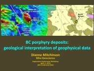
Final Report - Geoscience BC
Final Report - Geoscience BC
Final Report - Geoscience BC

Create successful ePaper yourself
Turn your PDF publications into a flip-book with our unique Google optimized e-Paper software.
… modelling the earth310 Victoria Avenue, Suite 309Westmount, QuébecCanada H3Z 2M9Tel: (514) 489-1890Fax: (514) 489-5536info@mirageoscience.comwww.mirageoscience.comDevelopment and Application of a Relational RockProperty Database System for British Columbia<strong>Geoscience</strong> <strong>BC</strong><strong>Report</strong> #: 2008-9a<strong>Geoscience</strong> <strong>BC</strong> Project #: 2006-015CAMIRO Project #: 06-E02November 7th, 2008
… modelling the earthTable of Contents1. Introduction........................................................................................................................... 12. Project Deliverables.............................................................................................................. 33. Project Data........................................................................................................................... 43.1. Data Distribution............................................................................................................. 43.1.1. Wireline Data.........................................................................................................................................43.1.2. Surface Sample Data .............................................................................................................................53.1.3. Borehole Core Data...............................................................................................................................53.2. Data on DVD Archive .................................................................................................... 84. RPDS Application ............................................................................................................... 124.1. General Overview ......................................................................................................... 124.2. Data Model.................................................................................................................... 134.3. Web Interface................................................................................................................ 165. Application Study................................................................................................................ 17Appendix 1 - Rock Properties Workshop Outline................................................................... 19Appendix 2 - DVD Data Archive ............................................................................................... 21
… modelling the earthList of FiguresFigure 1. Spatial distribution of data from <strong>BC</strong> entered in RPDS. The source of base layers is the <strong>BC</strong>GS Map Placeweb server. Map coordinates are in NAD83 Albers equal area conic projection. Surface samples are denotedby red circles, borecore samples by blue circles, and borehole wireline locations by white circles. ...................8Figure 2. Directory structure of data contained on the DVD included with this report. Inset shows organisationalstructure of borehole wireline data.....................................................................................................................11Figure 3. Schematic diagram of a theoretical borehole showing the data distillation process performed in RPDS. ...13Figure 4. Schematic diagram of the simplified RPDS data model, leading to the generation of the RegionalProperties summary table...................................................................................................................................14Figure 5. RPDS web query interface displaying the results of an example data filter.................................................16
… modelling the earthList of TablesTable 1. Distribution of data from <strong>BC</strong> collected and entered into RPDS summarized by (a) data type, (b) physicalproperty, and (c) location. *SS-surface sample, <strong>BC</strong>-borecore sample, BH-borehole wireline data. † M-magneticsusceptibility, D-density, DC-density counts, C-conductivity, R-resistivity, GC-gamma counts, SG-spectralgamma-gamma, IP-induced polarization, SP-self potential, SPG-self potential gradient, T-temperature, TGtemperaturegradient, V-Velocity.........................................................................................................................7
1. IntroductionPhysical rock property data, systematically recorded and comparable using standard formats, isintegral to successful interpretation of subsurface geology from geophysics. This projectrepresents a foundation in building a useful database for British Columbia. This data release isthe result of a significant amount of work by Mira <strong>Geoscience</strong> and the Geological Survey ofCanada to produce a standardized, high quality dataset of nearly 900,000 data points for theprovince. A significant amount of industry data remains to be added to the database.In April 2006, CAMIRO submitted a Proposal for 'Development of a Rock Property Database for<strong>BC</strong>' to <strong>Geoscience</strong> <strong>BC</strong>. In August 2006, the Proposal was accepted after confirmation that asignificant amount of data existed to be entered into the database. Project 2006-015 started up inOctober, 2006 when Mira <strong>Geoscience</strong> was contracted by the Canadian Mining Industry ResearchOrganization (CAMIRO), for a one year project involving the assembly and organization ofphysical rock property data for the Province of British Columbia. A large amount of rockproperty data exist for <strong>BC</strong>, however this data was in various hardcopy and digital formats,archived at many locations across the country making it difficult to amalgamate. One of theobjectives of this project was to bring together all available data for <strong>BC</strong> into standard digitizedformats on a common integration platform. The Project focused on rock property data collectedby the Geological Survey of Canada related to borehole surveys from the 1990’s, mapping of <strong>BC</strong>basins, TGI-3 program, and recent surveys in the Nechako Basin.The strategy was to compile the various rock property data for <strong>BC</strong> into “RPDS” (Rock PropertyDatabase System), a database application developed over the last 9 years by a consortium ofindustry and government agencies, and managed by Mira <strong>Geoscience</strong>. Data delivered in thisproject are in two formats: (1) summary database files on DVD to be downloadable from MapPlace and (2) files accessible from the Mira <strong>Geoscience</strong> server through the RPDS website. RPDSis an Oracle-based relational data management system, which brings together geological andgeophysical information and facilitates interpretation of rock properties and correspondinggeological description across geographic areas. This permits statistical and spatialcharacterization of the rock property environment for various ore deposit types in differentgeological settings. The significance of RPDS is that it provides a single repository for rockproperty data, as opposed to many disparate sources, thus allowing large-scale aggregation of1
data and in-depth analysis of rock property relationships. During the term of this project, publicaccess to RPDS data through Mira <strong>Geoscience</strong>'s website was considerably improved through aseparate contract with the GSC.Approximately 881,064 physical property measurements from borehole wireline, borecore, andsurface sample data from across <strong>BC</strong> have been procured from both government and industrysources. This data has been entered into RPDS at Mira <strong>Geoscience</strong>, adding to the existingarchive of greater than 5 million rock property measurements. In addition to data archiving andmanagement capabilities, RPDS also provides value-added summary tables of populationstatistics for various rock types across geographic areas. The summary tables for <strong>BC</strong> are includedon the DVD provided with this report. In addition, all data in RPDS are currently publiclyavailable through an online web interface at: www.mirageoscience.com/rpds.A significant amount of work was required to bring all data to RPDS standards. The result was asignificant “in-kind” effort by Mira <strong>Geoscience</strong> and GSC staff that exceeded the budget of theproject. The project would not have been possible without combined funding from <strong>Geoscience</strong><strong>BC</strong>, Mira <strong>Geoscience</strong>, the Geological Survey of Canada, BHP Billiton, Terrane Metals and TeckCominco.The remainder of this document describes the specific project deliverables, a description of theproject datasets, a summary of the RPDS application including the generation of the statisticalsummary output tables, as well as a description of the digital files included on the DVD with thisreport.2
2. Project DeliverablesDeliverables provided throughout the duration of the project timeframe:1. Abstract and location map at project start (Oct. 2006)2. Progress report (Nov. 2006)3. Poster presentation at Roundup 2007 (Jan. 2007)4. Entry of all available data for <strong>BC</strong> into RPDS (Oct. 2006-Jan.2008) and availability of datathrough the web interface on the Mira <strong>Geoscience</strong> web server.<strong>Final</strong> deliverables are:5. A workshop during Roundup 2008 for geoscience and industry users on how to access, useand apply the database (Jan. 2008). The workshop outline (Appendix 1) and workshopproceedings are included on the DVD with this data release (Appendix 2).a. Demonstration of the database system (presented by Sharon Parsons).b. An application study on how to analyze the data and to apply it to a field problemin the Mt. Milligan area (U<strong>BC</strong> study - presented by Nigel Phillips and DianneMitchinson).6. A summary report formatted to <strong>Geoscience</strong> <strong>BC</strong> standards to be submitted as a report on fieldactivities (Nov. 2008).7. A final report in digital format including: original input data from all sources for BritishColumbia with ready access to metadata, and physical rock property data and its correlativegeology (this document and accompanying files).a. A copy of the original input data from all parties re-formatted and organized intoa manageable folder structure.b. Copies of various summary tables generated by RPDS in Microsoft Excel andAccess format. The summary tables include: (a) general information metadatatables describing the characteristics of the <strong>BC</strong> data and (b) statistical summarycompilations of the physical rock properties of all boreholes/samples.3
3. Project Data3.1. Data DistributionRPDS currently houses 881,064 physical rock property records from borehole wireline, boreholedrillcore and surface sample data within British Columbia. Physical properties measured inboreholes include: density, magnetic susceptibility, conductivity, resistivity, density count,gamma ray count, IP, total field magnetics, spectral gamma-gamma ratio, SP, SP Gradient,single point resistivity, temperature, and temperature gradient. All data have been entered intoRPDS and meta-classifications, unit conversions, and coordinate system conversions have beenapplied, as well as general data quality assessment and control. The following sections describethe datasets in more detail. Tables 1a, 1b, and 1c summarize the <strong>BC</strong> data in RPDS. The spatialdistribution of data collected from <strong>BC</strong> and entered into RPDS is shown in Figure 1.3.1.1. Wireline DataBorehole wireline data (Figure 1, open circles) from 23 holes consisting of 198 logging runs,logged from 1986-1994, were provided by the Borehole Geophysics Group at the GeologicalSurvey of Canada in Ottawa. Mira <strong>Geoscience</strong> traveled to Ottawa to collect the digital andhardcopy data archived on multiple DVDs and over 150 hand-written field logging sheets.Multiple DVDs were copied from GSC archives, which contained various ascii-text filestransferred from original logging tapes. These ascii-text files contained raw and processed dataper logging run and, where available, lithology files per borehole. Logging run metadata werephotocopied from original hardcopy logging field sheets which provided critical informationpertaining to the logging runs as well as for deciphering raw data file names in order to associatethe appropriate raw data with processed data files. Additional metadata was acquired fromsupplementary hardcopy documents, open file reports, and personal communication with GSCcontributors. Where available, hole trace and assay files were generated manually from hardcopycorelogs and paper maps were digitized to pdf format. <strong>Final</strong>ly, data and metadata were formattedto RPDS import standards and entered into the system. This formatting involved applyinggeological and quality indicator classifications, performing unit and coordinate conversions, andminor data quality control. Due to the multiple sources of information, a significant amount ofwork was required to prepare the data for entry into RPDS. An additional 8 holes logged by the4
GSC in the Fraser Delta region (data largely for geotechnical purposes) were not entered at thispoint in time as the data was missing critical information such as processed data files andcorresponding geological rock descriptions.3.1.2. Surface Sample DataOriginally, physical property measurements from 3,666 surface samples were provided by theGeological Survey of Canada in Vancouver from various areas across <strong>BC</strong>. The data wereformatted and entered into RPDS. In a later phase of the project, new surface sample datatotalling 13,554 samples (Figure 1, red circles) were supplied by the GSC-Vancouver whichincluded an updated version of the previously supplied data. The older data were then deletedfrom the database and the new data entered. This new dataset contained mainly magneticsusceptibility and density measurements with a small population of conductivity measurements.The new data were provided as one large Excel spreadsheet. Prior to entry into RPDS, the datawere classified and formatted to fit RPDS import standards. For example, magnetic susceptibilitydata were converted from 10 -6 or 10 -3 SI to SI and density data from kg/m 3 to g/cm 3 . In somecases, rock codes and rock code descriptions were supplied in separate files. These rockdescriptions had to be attributed and then master lithologies assigned. Duplicate entries in theprovided datasets were removed and unique sample IDs (Location ID) were assigned. AlthoughRPDS uses an Excel spreadsheet for sample entry, each dataset required full reformatting prior toentry into the database system. A large part of the formatting was performed by Randy Enkin'sgroup at the GSC in collaboration with Mira <strong>Geoscience</strong>.In addition to the surface sample data supplied for this project, 118 density and velocitymeasurements from the Sullivan Deposit already existed in RPDS. This data is included in theoutput data files provided with this report.The surface sample data is a very important part of the database, particularly because it covers alarge areal extent of the province, compared to local borehole data. This data allows us tocharacterize the density and magnetic susceptibility of mappable rock units.3.1.3. Borehole Core DataThe borehole drillcore data (Figure 1, blue circles) were provided courtesy of Terrane MetalsCorp. The dataset was received as one Excel spreadsheet but needed a significant amount of5
eformatting and data preparation due to the large number of boreholes provided and to datastorage artefacts from the provider’s own database system, which were inconsistent with RPDSstandards. For example, the provider’s database stored depth as a depth start and depth end rangewhereas RPDS stores actual physical property data for samples at one depth value. Similarly tothe surface sample data, this dataset was attributed with rock code descriptions, masterlithologies assigned, measurements converted from 10 -3 SI to SI, negative and zero values wereremoved, and unique sample IDs (Location ID) were assigned.(a)General Data TypeCountHoles Logging Runs RecordsBorehole 23 198 854,851Borecore Sample 179 — 12,541Surface Sample — — 13,672Total 881,064(b)Geophysical Data SummaryParameterWireline Record CountSample/BorecoreTotalBorehole RecordRecord CountRecordsCount CountDensity 2,483 12 19,064 21,547Magnetic Susceptibility 23,644 19 127,516 151,160Conductivity 27 4 11,956 11,983Velocity 59 59Resistivity 21 107,063 107,063Density Count 8 26,637 26,637Gamma Ray Count 17 55,101 55,101Induced Polarization 11 50,122 50,122Total Field Magnetics 10 55,551 55,551Spectral Gamma-20 45,856 45,856Gamma RatioSelf Potential Gradient 11 55,459 55,459Self Potential 11 53,979 53,979Single Point Resistivity 10 55,976 55,976Temperature Gradient 22 94,918 94,918Temperature 22 95,653 95,653Total Records 26,213 198 854,851 881,0646
(c)Data Summary by LocationArea of Data Data Data TotalAcquisition Provider Type* RecordsPhysical Properties Measured †Adams Lake SS 559 M,D,CBowser &Sustut BasinsSS 1203 M,DCariboo SS 1865 M,DChilcotin SS 953 M,DCoastGSC-SS 81 MVancouverInterior Plateau SS 91 M(RandyKootenay Arc SS 1268 M,D,CEnkin,Nechako SS 6310 D,MCarmel Lowe,N. CascadesBobSS 8 MOminecaAnderson)SS 6 MQueenSS 850 M,DCharlotteRockies SS 68 MSkeena/Bulkley SS 67 MThompsonSS 225 M,DSullivan Previously inDeposit RPDSSS 118 D,VMt. Milligan TerraneMetals(Darren<strong>BC</strong> 12,541 MO’Brien)Chu Chua BH 43,899 C,DC,IP,M,R,SG,T,TGEquity Silver BH 55,495 C,D,IP,M,R,SG,T,TG,GCGoldstream BH 80,762 DC,GC,IP,M,R,SG,T,TGHighland GSC-Ottawa BH 77,211 DC,GC,IP,R,SG,SP,SPG,T,TG,MValley (JonathanLara/Buttle Mwenifumbo) BH 170,971 DC,GC,IP,M,R,SG,T,TGLakeMyra FallsD,GC,M,MAG,R,SG,BH 392,081SP,SPG,SPR,T,TGSullivanBH 34,432 C,DC,IP,M,R,SG,T,TG,GC,SPRTable 1. Distribution of data from <strong>BC</strong> collected and entered into RPDS summarized by (a) data type, (b) physicalproperty, and (c) location. *SS-surface sample, <strong>BC</strong>-borecore sample, BH-borehole wireline data. † M-magneticsusceptibility, D-density, DC-density counts, C-conductivity, R-resistivity, GC-gamma counts, SG-spectral gammagamma,IP-induced polarization, SP-self potential, SPG-self potential gradient, T-temperature, TG-temperaturegradient, V-Velocity.7
Figure 1. Spatial distribution of data from <strong>BC</strong> entered in RPDS. The source of base layers is the <strong>BC</strong>GS Map Placeweb server. Map coordinates are in NAD83 Albers equal area conic projection. Surface samples are denoted by redcircles, borecore samples by blue circles, and borehole wireline locations by white circles.3.2. Data on DVD ArchiveThis section summarizes the data contained on the DVD included with this report (Appendix 2).Within the root directory ‘<strong>Geoscience</strong> <strong>BC</strong> – Archive’, data have been organized into three sub-8
directories: ‘Input Data’, ‘Output Statistical Summary Tables’, and ‘Posters & Presentations’(Figure 2).1. Input Data - contains three sub-directories organized by data type: ‘Borehole-Wireline Data’,‘Borehole-Core Sample Data’, and ‘Surface Sample Data’.a. ‘Borehole – Wireline Data’ – contains a series of sub-directories organized byborehole name. Each borehole directory is divided into further sub-directoriescontaining the formatted data entered into RPDS as follows:i. AsciiFiles – lithology logs and look-up tables ± formation ± assay ± holetraceii. LiveRunData – default logging runsiii. MetaData – Excel files containing borehole and logging run metadata,which were manually entered into RPDS.iv. ZipFiles – compressed ZIP files of a) all raw data acquired for thatborehole and b) all processed data available for that borehole in addition tothe default logging runs.b. ‘Borehole – Core Sample Data’ and ‘Surface Sample Data’ – each contain twofurther self-explanatory sub-directories: ‘Original Files from Source Provider’ and‘Import Files for RPDS’.2. Output Summary Tablesa. Metadata_BH<strong>BC</strong>.xls - General metadata information entered into RPDS for eachborehole site from both wireline and borecore data types.b. Metadata_Data_SS.xls - General metadata information and actual physicalproperty data entered into RPDS for each surface sample site.c. RegionalProperties_BH<strong>BC</strong>.xls - Physical property population statistics fromborehole wireline and borecore data.d. RegionalProperties_SS_*.xls (4 files) - Physical property population statisticsfrom surface sample data per parameter. Four files representing the four physicalproperties measured on surface samples: conductivity, density, magneticsusceptibility, and velocity.e. Master_Lithology.xls - Summary of unique lithologies per area with MasterLithology Classification applied.9
Figure 2. Directory structure of data contained on the DVD included with this report. Inset shows organisationalstructure of borehole wireline data.11
4. RPDS Application4.1. General OverviewRPDS is designed to act as an integration platform to combine geophysical and geological datain order to effectively query rock property statistics for specific rock types across geographicareas. This allows for answering questions such as: What is the average density of basalts in theChilcotin area? or what is the average resistivity of a rhyolite in a VMS-type deposit? Thesetypes of questions are answered in RPDS by distillation of the large amount of data intomanageable, interpretable, queryable data tables. Figure 3 illustrates this distillation processshowing physical property logs for a theoretical borehole at depth including the associatedlithology, formation, and alteration information. Firstly, RPDS creates “geologic intervals” forcommon occurrences of lithology, formation, and alteration type (a geologic signature). Forexample, the first geologic interval is L1-F1-A1, the second is L2-F1-A2, and so on. Thisprocess is repeated at depth along the hole for each change in one of the geological variables.Then, for each interval, the physical property parameters are combined, calculating populationstatistics for that specific geological signature at that depth. The next phase of data distillationcombines each common interval, for example, all intervals with an L2-F1-A2 geologic signature(yellow zones on Figure 3) are combined, further summarizing the data. Next, the areaclassification (Country-Province-Area-Deposit) of each borehole is assessed and physicalproperties for all common geologic intervals across all holes within the same geographic area arecombined. Therefore physical properties of rocks with L2-F1-A2 signatures in the Sudburydeposit will not be combined with those having the same L2-F1-A2 signature in the Sullivandeposit. <strong>Final</strong>ly, this information is combined with the sample data having the same geologicalsignature for the same area. Therefore, all occurrences of L2-F1-A2 in any borehole or samplewithin the Bowser basin area in British Columbia are combined, providing, for example, onemean density value for a Sandstone with Argillic Alteration from the Brothers Peak Formationin the Bowser Basin area.12
Figure 3. Schematic diagram of a theoretical borehole showing the data distillation process performed in RPDS.4.2. Data ModelVarious tables in RPDS store information pertaining to all borehole and sample data entered intothe database. This information includes physical property data and metadata related to the entirelogging/sampling process (location, equipment, personnel, project descriptions, laboratorymethods, and processing/calibration history), as well as information related to geological units,and associated geochemical and geotechnical data. The simplified data model showing thesequence of tables used to generate the summary statistics described in the previous section isshown in Figure 4.13
Wireline DataRPDSSample DataProcess LogForced IntervalGeologicalSamplePhysical/SamplePropertiesRegional PropertiesFigure 4. Schematic diagram of the simplified RPDS data model, leading to the generation of the RegionalProperties summary table.The storage of borehole wireline physical property data in RPDS is based on the concept oflogging runs. Logging run data is stored in the Process Log Table, which contains the calibratedand processed logging run data for each borehole. This data is considered the “live data” inRPDS and is used for calculating the population statistics. Raw data is stored elsewhere in thedatabase for archival purposes only. The Process Log Table stores the physical property valuesfrom various depths as measured along the borehole. Since the depth intervals for eachmeasurement may vary per logging run, it is important to normalize these values to a constantdepth interval in order to correlate each of the parameters for different logging runs. This isperformed in the Forced Interval Table of RPDS.The Forced Interval Table interpolates the Process Log data for each physical property to acommon reference sampling interval of 10cm. Physical properties from the Forced Interval Tablemay be correlated since, as they are interpolated to the same depth, they represent measurementsof the same rock sample.In parallel, a significant amount of available laboratory measurements are stored in the SampleTable. This table accommodates the physical property data and all associated metadata fromlaboratory measurements of both borehole core samples originating from boreholes, and surfacesamples of varying origin.Geological information for borehole wireline, borecore, and surface samples are storedseparately in the database in the Geological Property Table. This table includes information on14
lithology, alteration, formation, geologic age, assay analyses, as well as space for storing corephotos which are rapidly visible on-the-fly. Lithology is stored as the specific lithological unitname using the local nomenclature from the data source. However, in addition to this naming, ageological “Master Lithology Classification” scheme has been developed to provide a moregeneral hierarchical description of the unit. This allows for consistent and more practical dataquerying within the RPDS environment. The geological data is combined with the borehole andsample data to produce the comprehensive Physical/Sample Properties Table.The Physical/Sample Properties Table is a composite table where logging run data taken fromthe Forced Interval Table and sample data taken from the Sample Table are correlated withgeological information. This is also where population statistics of physical properties as afunction of geological classification are pre-stored for rapid query. This table lists, for eachborehole, the mean values, standard deviations, and sample counts for physical properties perunique lithologic interval encountered in the borehole (as described in Section 4.1). At present,population statistics are calculated on the following 16 parameters, although others can be addedto this list: gamma-ray, potassium, uranium, thorium, density, magnetic susceptibility,conductivity, temperature, temperature gradient, IP, resistivity, self potential, self potentialgradient, velocity, neutron porosity, and caliper. This table is further summarized in the RegionalProperties Table.The Regional Properties Table is the final step in the data distillation process where physicalproperty data is summarized and stored by combining mean physical property values from thesame regional area that possess a common geological fingerprint, i.e. the sameformation/lithology/alteration combination. Therefore, the physical properties of all occurrencesof one geological unit in a borehole are averaged and combined with any other occurrences ofthat geological combination in the same area. As mentioned above, this provides one series ofstatistical summary values (mean, min, max, standard deviation, median, number of samples) foreach physical property, for each unique geological combination in the same regional geographicarea. Data for <strong>BC</strong> represented in the Regional Properties Table is included on the DVD providedwith this report (Appendix 2).15
4.3. Web InterfaceAll data within RPDS are publicly accessible through a map-based web query interface at:http://www.mirageoscience.com/rpds (Figure 5). The web interface is designed to communicatewith the RPDS Oracle database to provide rapid, up-to-date, query results on populationstatistics, including histograms, multiparameter cross-plots, and metadata. Queries can be refinedby physical property parameter, geological parameters, location information, location type(wireline vs. core vs. surface sample) and data quality. The map interface also includes a seriesof pre-rendered map layers for rapid visualization. These layers include base maps, geologicalmaps, and various symbolized layers showing the data distribution per physical propertyparameter. In addition, all data and selected metadata can be downloaded directly from thewebsite using the data downloading tools, which provide pre-rendered Log View plots forborehole data visualisation prior to download and various file format export options. <strong>Final</strong>ly,complete help documentation and a step-by-step tutorial on interface functionality is availablethrough the interface.Figure 5. RPDS web query interface displaying the results of an example data filter.16
5. Application StudyThe University of British Columbia Geophysical Inversion Facility (U<strong>BC</strong>-GIF) compiled acharacterization of the rock property environment of the Mt. Milligan ore deposit, using datafrom RPDS, in order to demonstrate the effectiveness of using physical rock property data inexploration models. The results of this study were presented as part of the Rock Propertiesworkshop at Roundup 2008. Presentations from Nigel Phillips and Dianne Mitchinson areincluded in the conference proceedings on the data DVD (Appendix 2). A written summary ofthese two presentations, compiled by Tom Lane of CAMIRO, is provided in a separate report:<strong>Geoscience</strong> <strong>BC</strong> <strong>Report</strong> 2008-9b.17
Appendix 1 - Rock Properties Workshop OutlineShort Course / Workshop for ROUNDUP 2008Sunday January 27, 2007Westin Bayshore Hotel Conference CentreSalon 3Vancouver, <strong>BC</strong>Extracting Geology from Geophysics and the Application of Physical Rock Properties toImprove Exploration TargetingParticipants: CAMIRO, Mira <strong>Geoscience</strong>, University of British Columbia MDRU and GIF, Geological Survey ofCanada, DGI, Schlumberger, <strong>Geoscience</strong> <strong>BC</strong>, <strong>BC</strong> Geophysics SocietyMorning Session: Principles and Tools8:20 to 8:30 Introduction – Tom Lane, CAMIRO8:30 to 9:10 Overview of Borehole Geophysics: Advances in the Utilization of Physical Properties –Unlockingknowledge and savings opportunities from exploration through production mining – MarkHammer, DGI <strong>Geoscience</strong> Inc.9:10 to 9:50 Borehole Gravity Applications in the Petroleum Industry – Harold Pfutzner, Schlumberger9:50 to 10:10 Coffee Break10:10 to 10:40 Use of Rock Properties to Refine Inversions – Nigel Phillips, Mira <strong>Geoscience</strong>,Nick Williams, U<strong>BC</strong> and Dianne Mitchinson, U<strong>BC</strong>10:40 to 11:10 Rock Properties and Drill Hole Targeting – John McGaughey, Mira <strong>Geoscience</strong>11:10 to 11:30 Panel Discussion / Q&A: Use and Value of Rock Property Data – Morning Speakers11:30 to 12:30 LunchAfternoon Session: Case Studies12:30 to 1:00 Rock Property Database System: A Rock Property Data Integration Tool for <strong>BC</strong> – Sharon Parsons,Mira <strong>Geoscience</strong>1:00 to 1:15 Rock Property Measurement and Compilation – Randy Enkin, GSC1:15 to 1:50 Regional Applications to Models of Subsurface Structure - Mapping – Mike Thomas, GSCwith R.G. Anderson, R. Enkin, K. Ford, P. Keating, C.Lowe, M. Pilkington, GSC1:50 to 2:20 Improving Exploration Through Physical Property Analysis and Modelling: Example form Mt.Milligan Cu-Au Deposit – Dianne Mitchinson, U<strong>BC</strong> and Nigel Phillips, Mira <strong>Geoscience</strong>2:20 to 2:40 Coffee Break19
2:40 to 3:10 Synthetic Model Testing and the Titan 24 Distributed Acquisition Results at Kemess North: aCase History Leading to a New Discovery at the Kemess North Copper Gold Porphyry - JeanLeGault, Quantec <strong>Geoscience</strong>3:10 to 3:40 Borehole Geophysics applied to Athabasca Basin Geology, Alteration and UraniumMineralization - EXTECH IV Study – Jonathon Mwenifumbo, GSC3:40 to 4:20 High Resolution Geological Interpretation and Regional Characterization as Developed fromComprehensive Physical Rock Property Analysis, Fort a la Corne, Saskatchewan, Canada –Susanne MacMahon, Innovation <strong>Geoscience</strong>, Shawn Harvey, Shore Gold, Chris Deisma, DGI<strong>Geoscience</strong>, Roxanne Leblanc, Innovation <strong>Geoscience</strong>4:20 to 4:35 Way Forward to a National Rock Property Database – Tom Lane, John McGaughey20
Appendix 2 - DVD Data ArchiveSee attached DVD21
… modelling the earth310 Victoria Avenue, Suite 309Westmount, QuébecCanada H3Z 2M9Tel: (514) 489-1890Fax: (514) 489-5536info@mirageoscience.comwww.mirageoscience.comApplication of Physical Rock Property Data forBritish Columbia: Mt. Milligan Case Study<strong>Geoscience</strong> <strong>BC</strong><strong>Report</strong> #: 2008-9b<strong>Geoscience</strong> <strong>BC</strong> Project #: 2006-015CAMIRO Project #: 06-E02November 7th, 2008
… modelling the earthTable of Contents1. The Importance of Physical Rock Properties to Exploration........................................... 12. What is Measured? ............................................................................................................... 33. Physical Properties................................................................................................................ 44. Correlation of Measurements with Rocks .......................................................................... 54.1. Magnetic Susceptibility .................................................................................................. 54.2. Density ............................................................................................................................ 54.3. Electrical Conductivity ................................................................................................... 64.4. Grounded Electrical Methods (Electrical Resistivity and Induced Polarization) ........... 74.5. Audio Magnetotellurics .................................................................................................. 74.6. Radiometric Gamma Ray Surveys.................................................................................. 74.7. Seismology and Acoustic Velocity................................................................................. 85. Case Study of Mt. Milligan Porphyry............................................................................... 105.1. Summary of Results Presented at Roundup Workshop ................................................ 105.2. Conclusions from Demonstration Study....................................................................... 12
… modelling the earthList of FiguresFigure 1. Mineral physical properties: density susceptibility cross-plot........................................................................8Figure 2. Processes of rock physical properties: density vs susceptibility cross-plot....................................................9Figure 3. Mt. Milligan geology....................................................................................................................................13Figure 4. Mt. Milligan mineralization .........................................................................................................................14Figure 5. Geology and alteration related to mineralization .........................................................................................15Figure 6. Susceptibility data for rock types mapped at Mt. Milligan ..........................................................................16Figure 7. Unaltered vs altered andesites ......................................................................................................................17Figure 8. Trends in magnetic susceptibility at Mt. Milligan........................................................................................18Figure 9. Inversion approach .......................................................................................................................................19Figure 10. Mt. Milligan synthetic models....................................................................................................................20Figure 11. Shell models ...............................................................................................................................................21Figure 12. Unconstrained synthetic model inversion result.........................................................................................22Figure 13. Variations to Milligan model .....................................................................................................................23Figure 14. Detection of other targets - lower contrast .................................................................................................24Figure 15. Detection of other targets - smaller targets.................................................................................................25Figure 16. Detection of other targets - buried 150m....................................................................................................26Figure 17. Detectability of a Milligan-like target ........................................................................................................27Figure 18. Mt. Milligan unconstrained inversion result (a) and data fit (b).................................................................29Figure 19. Constrained inversion geologic reference model for monzonite stock......................................................30Figure 20. Constrained inversion geologic reference model for stock margin ............................................................31Figure 21. Constrained inversion: geometry inversion................................................................................................32Figure 22. Constrained inversion: geologic contact ....................................................................................................33Figure 23. Constrained inversion: drill-hole bounds ...................................................................................................34Figure 24. Constrained inversion: interpolated reference and bounds.........................................................................35
… modelling the earth
1. The Importance of Physical Rock Properties to ExplorationAdvances of proven geophysical methods and techniques to interpret and visualize geophysicaldata require physical rock property data to relate the key geological aspects of ore deposits andtheir host rocks. Petrophysical analysis of specific ore systems is required to determine whatgeophysical techniques can best be used to target mineralization. The explorationist must startwith a concept of the ore deposit model which then provides clear guidance about possiblephysical property contrasts and can guide selection of the appropriate geophysical methods, theirappropriate use and how to interpret them. Various types of rock property data provideinformation on mineralogy, texture, grain size and porosity. Most importantly, differenttechniques exhibit contrasts that can then be imaged to reveal geometries between rock bodies.The process starts with a concept exploration model then data needs to be acquired that includesmeasurements of rock samples, outcrops and drill core. A preferred method is to measure a rangeof parameters from probes lowered into boreholes. Borehole measurements require planning fora budget as part of drilling programs, access to a representative number of boreholes, cost andtime, calibration of instruments and attention to the consistency of type of data received. If sucha plan is considered prohibitive, a company can measure selective borehole cores andrepresentative rock types to guide initial interpretations of geophysical surveys. Any programneeds communication between the geologist with respect to the geological model and thegeophysicist with respect to the geophysics. For all rock property data measured, a spreadsheetneeds to be set up to record the geophysical parameter, the location by GPS coordinates, the rocktype and the geological formation. It is also useful to record mineralogy, modal geochemistryalteration type as a confirmation of the rock type. Metadata is always important to enter into datafiles such as the method of geophysical measurement.The integration of all geological, geophysical and geochemical data into a 3D GIS model is thenext step and constitutes around 80% of the work. The whole earth models that are constructedshould provide structural geometry, lithological units, and alteration among other aspects.Geophysical data can be modeled synthetically as a forward model that krigs and smooths the1
geophysical data. The geophysical model is then compared to reference models, 2D models ofisosurfaces of geophysical parameters that are fitted to geological maps and sections. There areseveral programs available to invert geology-geophysics into 3D images, VPmg andGeomodeller. A number of geophysical inversion codes recover geophysical rock properties tothe whole earth model. These inversions may be unconstrained or constrained relative to thegeological patterns of the reference models. In constrained inversions the rock property data iskrigged to fit the geological boundary constraints. The inversion models give guidance on whatgeophysical parameters have sufficient magnitude and contrast such that a geophysical surveywould reveal drill targets.At early stages of exploration it is useful to construct synthetic forward models and inversionsbased on known geophysical surveys and rock property measurements. If these models suggestthat the ore type target could be detected geophysically, this exercise would provide rationale tofund new geophysical surveys and rock property measurements.2
2. What is Measured?Measured physical rock property data are a means of linking geophysical surveys to subsurfacegeology. The advent of forward modeling and inversion of geophysical data along with theability to rapidly compute large amounts of data on desktop computers now enables us tonumerically modify geophysical data in 3D that approximates the geometry of geological bodies.To inform these computer models it is important to redraw geological maps and cross-sections interms of the geophysical properties of the geological units. These geological – geophysicalreference maps should be simplified to emphasize units with distinct densities and / or magneticproperties and boundaries with physical contrasts. Other parameters such as resistivity,conductivity and chargeability may be mappable parameters. Direct rock property measurementsof this type of data are less available. Reference maps can then guide the computer models toselect a forward model or inversion that best fits the geology.Solutions for forward models and inversions of geophysical data are non-unique, in other wordsseveral geological geometries can explain a geophysical anomaly. Preferred geometric solutionscan be identified by preparing a likely geological geometry that corresponds to the knowndistribution of physical rock properties for rock units. Data for density and magneticsusceptibility are more commonly measured and available. Also inversions for gravity (densitycontrasts) and magnetics are more easily computable with existing codes. Rock property data forresistivity, chargeability and conductivity are less commonly measured. Also the computing timeand complexity for electrical properties and conductivity are a greater challenge. Geophysicalcontract companies do provide these services however.Sulphide geochemical analyses can be used as a proxy for chargeability. Electrical conductivityof samples can be directly measured in laboratories. Density is commonly measured by retrievalof a rock sample and measurement by weight in air – weight in water technique. An alternativeindirect measurement of relative density is by borehole measurement of gamma-gamma andmise-a –la-masse. It is also common to measure seismic velocities and acoustic properties ofrocks. Spectral gamma logs are means of correlation of rock units with radiometric surveys.Field spectral measurements are used to constrain airborne gamma spectral surveys. Table 1 listsa number of physical properties that are measured.3
3. Physical PropertiesProperty Method of Measurement UnitsMagnetic susceptibility susceptibility meter x 10 -3SIKoenigsberger ratio measured from oriented core Kn = remanence/ ms x fieldDensity wgt in air – wgt in water; spectral gamma gamma; g/cm3gravity meter; borehole gravity meterConductivity mhos/m; siemens/m (S m -1 )Resistivity apparent resistivity with applied current ohm meters x 104 or ohm mChargeability transient voltage millivolt/voltGamma Ray MeV gamma rays; calculate eUranium, eThorium; eThorium v ePotassium (ppm)Spectrometry ePotassium % potassiumSeismic velocity elastic wave velocity km/sec = vAcoustic impedance z = v x ρPorosity %Temperature measure degrees centigrade milliKelvin/m; ºc/mGradientNatural Gamma cps4
4. Correlation of Measurements with Rocks4.1. Magnetic SusceptibilityMagnetic ground, airborne surveys and magnetic susceptibility data is commonly available andrelatively inexpensive to acquire. High resolution airborne magnetic surveys are increasinglycovering the land and can reveal the detail of geological structure within the 200 m of thesurface. As a result inversions and 3D models of magnetic data are commonly used byexploration companies. Magnetic susceptibility is controlled by accessory minerals in a rock,principally terrimagnetic magnetite and pyrrhotite, distribution of which may not be uniform forsuch reasons as concentration in distinct layers, uneven hydrothermal alteration or variableconditions of differentiation, eg. oxygen fugacity in plutonic rocks. The upside of application ofmagnetics is that magnetic susceptibility measurements are easy to collect in the field and drillcores. The degree of variation of magnetic susceptibility is much greater than density, zero to300 x 10 -3 SI compared to 2.0 to 3.2 g/cm 3 . As a result much more variation and apparent detailcan be seen on high resolution magnetic maps, particularly first derivative maps. (Figs. 9 and 10Thomas). Geological units can have varying amounts of magnetic remanence with a suppressedsignal on airborne magnetics.. To understand the potential for remanence get type rock samplesmeasured for magnetic remanence and induced magnetism. The relative dominance ofremanence over induced magnetism is reported as Koenigsberg ratio or Q values.4.2. DensityDensity reflects mainly the principal minerals that constitute and define a particular rock type,eg. quartz, feldspar and pyroxene. In most rock types the defining mineralogy is essentiallyuniform, hence density characteristics are also uniform. For this reason density variation is apreferred method for mapping rock units. Intrepid Geophysics’ surveys of the Broken Hillterrane reported that that mapping of the variance of the density, the standard deviation, is aneffective way of mapping rock units. Gold exploration has found gravity effective at mapping thegeometry and structure of greenstone belts and specific intrusion targets in greenstones orsedimentary formations. On the downside it is expensive to acquire ground and airborne gravitysurveys in sufficient detail to image geology. The increasing access to airborne gravitygradiometer surveys means that in the future more density inversions will be possible. The AGG5
surveys have excellent resolution of 0.4mgal per 500 m. Ground follow-up can achieve 0.01mgal over < 1 m. Noise related to topographic and bouguer effects hinders the use of thistechnique for detailed geology. Borehole gravity meters are being developed that can measuretotal bulk density over vertical intervals to depths of 2000 m. The bulk density data needs toconsider density of the rock relative to the amount of pore space.A comparison of magnetic susceptibility versus density can be used to differentiate mineralogy,rock types and alteration (Figures 1 and 2). Carbonate, quartz and amphibole are less dense thensulphides and hematite. Olivine falls in between. Magnetite and pyrrhotite have distinctivelyhigh magnetic susceptibility and density, in other words these parameters can map outmineralization. Density variations can be used to differentiate metamorphism, igneous zonationand weathering. One of the more useful tools is that alteration destroys magnetic susceptibility asa result of the destruction of magnetite and mafic minerals.4.3. Electrical ConductivityConductivity is the most effective tool for Cu-Ni and other massive sulphides. Conductance,conductivity x thickness, is important to distinguish bodies of massive sulphide. Ability to detecthigh conductance, > 10 3 Siemens, is important for detection of nickel ores. Connectivity ofconductive minerals is essential. Some minerals like magnetite have intrinsically highconductance, but commonly are not connected. The comparison of density to electricalconductivity is a useful way to distinguish sulphides from iron rich silicates and oxides that mayform conductive patterns.In uranium exploration in Athabasca large moving loop EM and airborne EM surveys have beeneffective mapping graphite zones and regional fault zones. Similarly in gold exploration in-loophelicopter EM surveys (Newtem and VTEM) are effective ways of mapping graphitic structuralzones. Regional apparent conductivity can map out graphitic formations as a means of mappingregional geology from airborne EM surveys. In the Athabasca favourable basement terranes ofmetasedimentary rocks are mapped geophysically by low magnetic susceptibility and highapparent conductance in contrast to magnetic granitic terranes.6
4.4. Grounded Electrical Methods (Electrical Resistivity and Induced Polarization)Resistivity can be measured by probes in boreholes or directly from drill core. Resistivity is mosteffective in sedimentary basins. It has been most effectively employed to map alteration arounduranium and gold deposits. 3D pole to pole distributed array acquisition and deeper seekingaudio magnetotelluric surveys are able get the data required to do effective 2D and 3D inversionsacross alteration zones. Resistivity is less effective for direct ore targeting.Induced polarization (IP) has a long history of use and is effective at mapping large areas ofdisseminated pyrite mineralization. The method images large areas of phyllic alteration withdisseminated sulphides, as well as large pyrite–sericite alteration zones in volcanic systems.Geology – IP inversions take significant computational time and are still under development.Any targeting generated by inversions require thorough integration with deposit models andgeology of the target areas. Complete borehole logging is needed to sort out alteration zonationand vectoring in such large alteration systems. IP probes can be used in boreholes. Geochemicalanalyses of sulphur and visual estimates of sulphides in boreholes are inexpensive proxies forborehole IP surveys. IP surveys are also effective for Ni-Cu-PGE veins with high electricalchargeability. Radio imaging (RIM) is a complimentary tool, used across two boreholes, that canimage highly conductive veins.4.5. Audio MagnetotelluricsAudio Magnetotelluric Surveys (AMT) are increasingly popular for mapping conductivity andresistivity below 700 m. It is being applied to deep nickel and uranium exploration and providesa deeper extension to shallower IP-DC resistivity surveys. The latest software is venturing into3D imaging of conductivity and resistivity.4.6. Radiometric Gamma Ray SurveysGamma rays penetrate approximately one half meter into the ground. Spectral gamma andmagnetic surveys are useful for regional mapping of porphyry systems and some uraniferousterranes, for intrusions and uraniferous mineralization and boulders. The integration of magneticswith radiometrics in these surveys is quite effective for the corresponding detection of faultstructures and magnetite-rich intrusive zones and potassic alteration. Such spectral gamma ray7
surveys are commonly calibrated by ground spectral surveys on outcrops. Existing spectrallogging systems like Hylogger and hand-held short wave infrared instruments, PIMA II and ASDFieldspec, provide rock property readings that can be integrated with airborne gamma surveys.4.7. Seismology and Acoustic VelocityShallow 2D to 3D seismic surveys have been successfully employed for imaging complex faultstructures in the Athabasca basin and complex fold and fault structures that control goldmineralization (eg. Yilgarn, western Australia). Also the low acoustic velocity of massivesulphides lends these ore bodies to be detectable in cross-hole seismic surveys as documented atSudbury and Bathurst, New Brunswick. Faults and associated zones of rock weakness alsoappear as zones of low velocity in 2D and 3D surveys. Rock properties that are measured arerelative seismic velocity in meters per second (m s -1 ) and impedance (velocity + density) that is ameasure of reflectivity. Crystalline rocks tend to have high velocities and impedance comparedto sedimentary rocks. Plots of density versus seismic velocity are a useful way to differentiatedifferent lithologies to identify the best impedance contrasts for potential seismic surveys.Mineral Physical Properties: density–sus. sus. cross-plotRock Property ModellingFigure 1. Mineral physical properties: density susceptibility cross-plot8
Rock Physical Properties – Processes: density–sus. sus. cross-plotSerpentinisationMineralisationMetamorphismWeatheringIgneousdifferentiationFigure 2. Processes of rock physical properties: density vs susceptibility cross-plot9
5. Case Study of Mt. Milligan PorphyryBy Dianne Mitchinson and Nigel Phillips5.1. Summary of Results Presented at Roundup WorkshopTerrane Metals Ltd. contributed 12,541 measurements from 180 boreholes along with geologicaldescriptions and corresponding 2D and 3D models. Samples were measured every 1 to 2 metersdown each borehole. From this data and local geophysical surveys an analysis was done of theapplication of magnetic susceptibility. The recommended steps of analysis are summarized alongwith representative illustrations.Step 1 – Assemble Local and Regional Magnetic Surveys. High resolution surveys
c. Are there any relationships between susceptibility and mineralogy? Can susceptibilityact as a proxy for mineral abundance?d. Findings: Rock types have bimodal distribution of magnetic susceptibility. There is anabsence of systematic patterns (Figures 6 – 7).Step 7 – Examine the variation of magnetic susceptibility in borehole logs. They found that thehighest magnetic susceptibilities are with magnetite associated with potassic altered andesiteadjacent to the monzonite intrusion. Unaltered andesites have low susceptibility. Potassicalteration in the monzonite has moderate susceptibility related to biotite and minor magnetite(Figure 8).Step 8 – To examine the spatial relationships of magnetic susceptibility the physical propertiesare incorporated into inversion models. Modelling is done in three stages: 1. construction of asynthetic model, 2. Construction of a constrained inversion and 3. Interpretation of theinversions.a. The synthetic model. The exercises by Dianne Mitchinson illustrated how syntheticmodels can be used to show expectations of detectability as target contrast, size and depthis changed. A series of synthetic models were constructed.i. The mineralized stock has magnetic susceptibility (ms) of 32.3 x 10 -3 SI comparedto a background of 0.68 x 10 -3 SI (Figure 11).ii. Forward modeling of the distribution of ms data results in an annular geometry. Themodel uses a mesh of 2,525 m x 2,325 m with cell sizes 25 m on each side (Figure11).iii. An unconstrained synthetic model inversion generates a cone of anomalous ms thatapproximates the location of the intrusive stock. Higher ms values are at the top ofthe model and lower values at the bottom. Models indicate ms values similar towhat was measured in boreholes (Figure 12).iv. Experimentation with reduced contrast, smaller targets and burial at 150 m illustratethat detection would be more difficult. At depth a similar target could be detectedbut the target would be smoother with less definition. Targets of small size could11
merge into the background. Deposits of similar size but lower contrast could beidentified from surface surveys (Figures 13 – 18).b. Constrained inversions require significant input by geologists and communication withthe geophysicist, The Mt Milligan demonstration provided a model of the deposit geologyand the spatial distribution of magnetic susceptibility (ms) in boreholes, A series ofinversion models were constructed with each case based on specific constraints as follows:i. geological reference model for the monzonite stock (Figure 19)ii. geological reference model for the stock margin (Figure 20)iii. geometry of the magnetic body assuming uniform ms. This image providessignificant detail on the shape of the magnetic altered margin of the stock (Figure21)iv. the geological contact. Note that the shape of the magnetic anomaly changesconsiderably compared to the unconstrained model (Figure 22).v. drill hole controlled boundaries of the magnetic susceptibility. The borehole datasignificantly changes the configuration of magnetic bodies to steep planar zones(Figure 23).vi. Interpolated reference and bounds where values are krigged. This version alsoshows a steep geometry that corresponds faults and dikes (Figure 24).5.2. Conclusions from Demonstration StudyThe study has demonstrated that a limited amount of data can be informative. However, the dataneeds to be well correlated and rock types identified. It is essential to examine and to understandthe relationship between rock physical properties and geology, alteration and mineralization.This demonstration shows that physical properties can be used to refine inversions in manydifferent ways. As well, synthetic models can be used to test whether the geophysical methodcan be used to detect a deposit. The similarity of the different methods to constrain inversionsimplies that the data is good and the method robust. The constraint methodology depends on theinversion methodology, the amount and type of data and the exploration goal.12
Mt. Milligan - geologyRock Property ModellingFigure 3. Mt. Milligan geology13
Mount Milligan geologyFrom Jago (2008, MSc thesis, unpublished)• Cu-Au porphyry deposit• Monzonite stock hosted within andesites tobasaltic andesites, and related volcanicsedimentary units (tuffs, breccias, conglomerates)• Tilted, and faulted stratigraphy• Mineralization spatially associated with themonzonite stock, and hydrothermal breccias4 main mineralized zonesFigure 4. Mt. Milligan mineralization14
Geology and alteration related to mineralization• What defines mineralized zones at Mount Milligan?– Boundaries of monzonite stock, and associated dikes– Mineralization in permeable units, hydrothermal breccias, conglomerates,upper and lower trachytes, faults– Proximal biotite-Kspar-magnetite-chalcopyrite (‘potassic’ alteration)From Jago (2008, MSc thesis, unpublished)DWBX ZoneWBX ZoneMBX Zone“66” Zone– Distal epidote-albite-actinolite-pyrite (‘propylitic’ alteration)– Shallow, low T carbonate-sericite alteration (anomalously high gold grades;permeable pathways)Figure 5. Geology and alteration related to mineralization15
Susceptibilty data for rock types mapped at Mount Milligan12000200040002006004003000.001 0.01 0.1 1 10 100 1000Magnetic Susceptibility x 10 -3 SI UnitsAndesiteAndesite/monzonitehybridMonzoniteDioriteHydrothermalBrecciaTrachyteFaulted materialWhy multiple populations?Figure 6. Susceptibility data for rock types mapped at Mt. Milligan16
Consider alteration - may explain the various susceptibility populations observed in each rocktype/sub rock-typeUnaltered vs altered andesites250Unaltered0120Potassic alteration03000Propylitic alteration3000Propylliticoverprintingpotassic alteration20Carbonate alteration00.001 0.01 0.1 1 10 100 1000Magnetic Susceptibility x 10 -3 SI UnitsFigure 7. Unaltered vs altered andesites17
4 1 9 . 7 12 55 07 51 0 01 2 51 5 01 7 52 0 02 2 52 5 02 7 53 0 03 2 53 5 03 7 54 0 00R O C KA L T N0M A G S U S2 6 60 5m g0cp20 2 0p y02 55 07 51 0 01 2 51 5 01 7 52 0 02 2 52 5 02 7 53 0 03 2 53 5 03 7 54 0 04 1 9 . 7 1Trends in magnetic susceptibility at MilliganMonzonite Hybrid AndesiteAndesite0m420mLow magnetiteabundance, lowsusceptibility, ingenerally unalteredandesitic rocks.Increased pyrite withcarbonate/epidotealteration.Potassic alterationPropylitic alterationCarbonate alterationPropylitic overprintingpotassic alterationCarbonate overprintingpotassic alterationPotassic alteration in andesite yields magnetite.Overprinting by other alteration assemblagescauses irregular susceptibilityWhere unaltered – a drop in susceptibilityWhere potassic alteration occurs in monzonite,K-spar/biotite forms preferentially (less Fe formagnetite) thus slightly lower susceptibilities?GeolAltnMagSusMagCpyPyFigure 8. Trends in magnetic susceptibility at Mt. Milligan18
Inversion Approach• Physical Property-based Inversion–U<strong>BC</strong>-GIFRock Property ModellingFigure 9. Inversion approach19
Mount Milligan synthetic models for case studyModel features– Used monzonite stock volume from Milligan 3D geologic model to build twosynthetic models (mineralized stock and mineralized ‘shell’)– Altered 2 initial models to explore variations (deeper, smaller, lowercontrast)– Susceptibility ofmineralized zones(potassic alteration)Potassicalteration ofandesite– Susceptibility ofbackground (andesites,monzonites, propyliticalteration)Potassicalteration ofmonzoniteFigure 10. Mt. Milligan synthetic models20
Mineralized stock, and mineralized shell modelsStock model – entirestock is mineralizedMag Sus ( SI Units)Magnetic susceptibilityvalues used:Target:0.0323 SI Units(32.3 x 10 -3 SI units)Background:0.00068 SI Units(0.68 x 10 -3 SI Units)View looking north at mineralized zone• Mesh 2525 m x 2325 m x1025 m• Cell size 25 m• Process: synthetic Milliganmodel is forward modeled(12.5 m x 50 m spacing, 50 mheight), noise and errors areassigned, and the resultingsynthetic magnetic dataset isinvertedShell model – boundariesof stock are mineralizedMag Sus ( SI Units)Figure 11. Shell models21
Unconstrained synthetic model inversion resultMag Sus ( SI Units)• Deeper highsusceptibility zone notwell detected• Max susceptibilityvalues very close to truevalues• Deeper highsusceptibility zone notwell detected• Max susceptibilityvalues close to truevalues• The low susceptibilitycore of the shell modelis detectedMag Sus ( SI Units)Figure 12. Unconstrained synthetic model inversion result22
Variations to Milligan modelLower contrast (half)Smaller targetBuried 150mFigure 13. Variations to Milligan model23
Detection of other targets - lower contrastMag Sus ( SI Units)• Deeper highsusceptibility zone notwell detected• Max susceptibilityvalues close to truevalues• Despite lower contrast,target is still welldetected• Deeper highsusceptibility zone notwell detected• The low susceptibilitycore of the shell modelis detected• Despite lower contrast,target is still welldetectedMag Sus ( SI Units)Figure 14. Detection of other targets - lower contrast24
Detection of other targets - smaller targetMag Sus ( SI Units)• Deeper highsusceptibility zone notdetected• Max susceptibilityvalues much lower thanknown valuesMag Sus ( SI Units)• Deeper highsusceptibility zone notdetected• Low susceptibility coreundetected• Max susceptibilityvalues much lower thanknown valuesFigure 15. Detection of other targets - smaller targets25
Detection of other targets – buried 150 mMag Sus ( SI Units)• Target not as distinctunder 150 m cover• High susceptibilityextends to depth• Susceptibility valuesmuch lower than knownvaluesMag Sus ( SI Units)• Target not as distinct• Low susceptibility corenot detected• High susceptibilityextends to depth• Susceptibility valuesmuch lower than knownvaluesFigure 16. Detection of other targets - buried 150m26
Detectability of a Milligan-like like target• Examples of info to be derived fromsynthetic modeling:Known target 0.0323 SI0.016 SI– Recovered susceptibility for deeper,and smaller targets are low– Buried target - targets at depth notobscured, but may be smoother, andsusceptibility spreads to depth– Smaller anomalies - if too deep, or tooclose to another anomaly, won’t beeasily detected– Lower contrast - may still besignificant enough to be detectedFigure 17. Detectability of a Milligan-like target27
Mt. Milligan – unconstrained inversion result(a)Rock Property Modelling28
Mt. Milligan – data fit(b)Rock Property ModellingFigure 18. Mt. Milligan unconstrained inversion result (a) and data fit (b)29
Constrained Inversion:Unconstrained ModelGeologic Reference Model: Monzonite StockReference Model0.0323 S.I.Rock Property ModellingFigure 19. Constrained inversion geologic reference model for monzonite stock30
Constrained Inversion:Unconstrained ModelGeologic Reference Model: Stock MarginReference Model0.0323 S.I.Rock Property ModellingFigure 20. Constrained inversion geologic reference model for stock margin31
Constrained Inversion:Unconstrained ModelGeometry InversionProvides geometry of magnetic body if it wasa homogeneous susceptibility of 0.04 S.I.Rock Property ModellingFigure 21. Constrained inversion: geometry inversion32
Constrained Inversion:Unconstrained ModelGeologic ContactContact ModelRock Property ModellingFigure 22. Constrained inversion: geologic contact33
Constrained Inversion:Unconstrained ModelDrill-Hole BoundsDH Sus. dataRock Property ModellingFigure 23. Constrained inversion: drill-hole bounds34
Constrained Inversion:Unconstrained ModelInterpolated Reference and BoundsKrigged valuesRock Property ModellingMatches known faults and dykesFigure 24. Constrained inversion: interpolated reference and bounds35