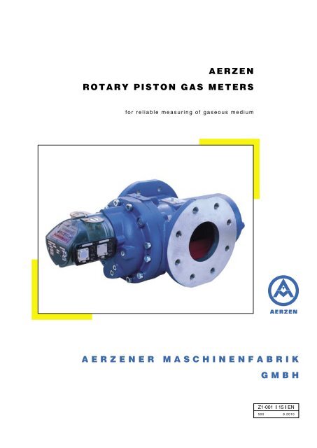
Aerzen Rotary Piston Gas Meters
Aerzen Rotary Piston Gas Meters
Aerzen Rotary Piston Gas Meters

Create successful ePaper yourself
Turn your PDF publications into a flip-book with our unique Google optimized e-Paper software.
<strong>Aerzen</strong> <strong>Rotary</strong> <strong>Piston</strong> <strong>Gas</strong> <strong>Meters</strong>Over 70 years of successful experience<strong>Rotary</strong> piston gas meters have been manufactured since 1930 by <strong>Aerzen</strong>er Maschinenfabrik, one of the largestand oldest manufacturers worldwide. The basis for the design of the gas meter series is from many years ofexperience and continual dialogue with the end users, as well as using the harmonized EU-standards whichwill apply to all installations within the European Market. They are manufactured in accordance with the <strong>Aerzen</strong>tradition for quality corresponding to the quality assurance system, certified to DIN ISO 9001 and as per pressuredevice guideline DGRL 97/23/EG.Advantages:• Largest series of all competitors up to G 4000 (6.500 m 3 /h)• In series HTB design 5 bar operating pressure (G 40 - G 400)• Extended measuring range up to 1:160• Guaranteed measuring resistance within the calibration validity• Re-calibration every 16 years, unlimited for sizes up to G 1600 and larger• Reduced assembly dimensions (3 x DN possible)• Minimum maintenance, oil change intervals are 16 years on gas streams with utmost purity• Double roller type counter in series makes change of the flow direction at site possible without supervision of acalibration inspector• No measured orifices required compared to turbine wheel counters• Pressure and temperature connections are available in the housing on both sides (please refer to page 9)• Flexible customer-orientated solutions by additional equipment (please refer to page 8)2
Mode of operationThe <strong>Rotary</strong> piston gas meter is used for volumetricmeasurement of gas in closed piping systems.A pressure difference between the inlet and outlet ofthe gas meter produces a rotation torque on the rotarypistons. Once the rotation torque exceeds the moment ofinertia of the rotors, they begin to rotate in the direction ofthe arrows. During rotation, the cavities formed betweenthe rotors and the cylinder housing fill and discharge witha volume of gas. Therefore, the rotation of the pistons isproportional to the gas flow. The rotation is transmittedvia an adjusting gear to the counter, it records the gasvolume that has passed across the gas meter in actualcubic meters.The rotors turn very freely, because no metal contacttakes place within the measuring chamber. Measuringstarts at ∆p < 0.1 mbar and Q~1/1000 Q maxFields of application<strong>Aerzen</strong> rotary piston gas meters are designed formetering gas volumes. They are primarily used• in the public gas supply network - in gas transferand metering stations - for the measurement of gasconsumption and distribution in municipal and gasprovider facilities, as well as the gas consumed by endusers. e.g. steelworks, tile and glass making plants, aswell as schools, hospitals, apartment complexes etc.• in the chemical industry for metering gas consumption,gas distribution, also for process gas flow control.• in the car industry, for measuring the inlet air flow ofcombustion engines on test and research benches.• in the industry for measuring the consumption ofcompressed air• in the compressor technology for determination of theair volume generated on test benchesMeasuring accuracy, flow resistanceWith increasing gas prices, high accuracy and reliabilityof measurements are paramount. <strong>Rotary</strong> piston gasmeters offer these advantages over other gas metertypes. The accuracy of repetitive measuring is excellentand under normal conditions remains constant fordecades. After approximately 50 years of operation,re-calibration of <strong>Aerzen</strong> gas meters has shown virtuallyno deviation from the accuracy curve at new condition.A special manufacturing process guarantees exactingtolerances and the highest precision of this „Roots type“measuring system.A measuring range of up to 1:160 and even higher cantherefore be achieved as a standard. The optimal designof bearings and gears results in very smooth operationand low pressure drop ∆p.The pressure drop is nearly proportional to the specificweight of the gas and to the square of the gas flow.The ∆p values for the various gas meter sizes at Q maxare given in the table on page 6.∆p max(at Q max)pressure dropQ minflow volumeat ρ = 2 kg/m 3at ρ = 1 kg/m 3Q maxTypical pressure drop diagram for gas specific weightsρ = 1 kg/m 3 and ρ = 2 kg/m 3.3
Design and layout<strong>Rotary</strong> piston gas meters are manufactured for pressurestages p max10 bar, 16 bar. The pressurized parts withinthe gas meter are made of nodular cast iron, up to sizeG 1000 the rotors are made of anodized light alloy, aboveG 1000 they are made of grey cast iron. The anodizinglayer achieves a considerably higher resistance to wearof the piston surface.Oversize bearings and ground timing gears ensure quietvibration-free operation. A frictionless and pressure tightmagnetic coupling transmits the rotation from the pressurechamber to the drive shaft of the counter mechanism.This shaft carries the magnet core and drives the countermechanism in its isolated housing. The counter mechanismfeatures a closely stepped adjusting gear and 8 countingwheels.The gas meters up to size G 400 are flange mounted.Larger gas meters feature bolted-on mounting feet.All <strong>Aerzen</strong> gas meters meet the requirements of DVGWsheetG 492/II and DIN 30690 T 1, DIN 3230 T 5 andpressure device guideline DGRL 97/23/EG.They are subject to the pressure and leakage tests prescribedby these standards.The housing materials correspond to the requirements ofDIN EN 13445-2 with PED-QM certification with acceptancetest certificate EN 10204/3.1.B.<strong>Aerzen</strong> rotary piston gas meters already now meet theessential requirements of the future European <strong>Rotary</strong> pistongas meter standard EN 12480. Until this standard becomesbinding the previous legal regulations (calibration law,calibration order) apply, according to which the <strong>Aerzen</strong>erMaschinenfabrik manufactures, tests and approves itsproducts. Works certificates for tests acc. to EN 12480can be issued on request.<strong>Gas</strong>es<strong>Aerzen</strong> gas meters can be used with any noncorrosivegas according to DVGW-worksheet G 260, includingnatural gas, town gas, coke oven gas, refinery gas, propane,butane, liquid gas/air mixtures, methane, ethylene,hydrogen and other gases.Operating temperatureThe normal operating temperature range is between -10°Cand +40°C. Please contact our sales department for higheror lower temperatures. The gas meters can be stored attemperatures between -20°C and +60°C.High Temperature Resistance (HTB - 5 bar)In the case of a fire, the gas meter must not be an additionalhazard. Therefore, the <strong>Aerzen</strong> gas meter sizes G 40to G 400 are designed to fulfill the HTB-requirements ofDIN 3374.single rowball bearingpressure measuringconnectiontemperature measuringconnectiontiming gearsmechanicaloutput (optional)double rollertype counteroil chamber4rotary pistonoil chambermagnetic couplingadjustment gearindication„piston rotating“counter housing,swivels
Mounting positionsThe meters are designed to operate in horizontal andvertical flow directions, the counter can be rotated(without supervision of a calibration inspector.)Sizes G 40 to G 400The oil level control screws are positioned forhorizontal and vertical flow. The gas meters cantherefore be rotated through 90 degrees, the counterhousing must be rotated to fit the actual orientationwithout supervision of a calibration inspector.Sizes G 650 to G 4000The oil level indicators and the mounting feet can be relocatedfor horizontal and vertical flow. The gas meters can therefore berotated through 90 degrees, and the counter housing can be rotatedwithout supervision of a calibration inspector.<strong>Aerzen</strong><strong>Rotary</strong> <strong>Piston</strong> <strong>Gas</strong> <strong>Meters</strong>G 160, PN 16More flexibility by new counter designThe <strong>Aerzen</strong> rotary piston gas meters are equipped with anew double roller type counter, which enables uponcommissioning an adjustment to the flow directionwithout adjustment of the counter and withoutsupervision by a calibration inspector.Consequently, less stock is necessary and costs ofshort-term modifications regarding planned projectscan be avoided. The adjustment at site to the requestedflow direction can be effected easily and without the useof tools. The counter provides two displays working inopposite direction which are covered by a shield whendelivered. After determination of the flow direction, the coveris removed and the corresponding display becomes visible.If necessary - the counter head can be turned by 90° byloosening 2 hexagon socket screws.Further features:• 1 unit low frequency impulse generatorinstalled as standard• further impulse generators(high- or low frequency) can be added• retrofit of mechanical output drivepossible acc. to DIN 33800Installation and maintenance<strong>Rotary</strong> piston gas meters require no inlet orifice’s. Both the gas andthe pipe line must be clean; it is advisable to temporarily install astarting strainer. The meters are splash lubricated.The oil level can be checked by oil level indicators. In case of normaloperation, an oil change is only necessary every 5 years (whenmeasuring gas streams with utmost purity every 16 years only). Thecounter does not require any particular maintenance for severalyears. For further details please refer to the corresponding operatingmanual.<strong>Aerzen</strong> <strong>Rotary</strong> <strong>Piston</strong> <strong>Gas</strong> <strong>Meters</strong> - universalflow directions (counter rotation withoutsupervision of a calibration inspector.5
Measuring ranges, sizes, pressure losses, volume per revolution U pConnectingflange side<strong>Gas</strong>metersizemodelnumberMeasuring range which can be calibratedEG-certificationEWG 1.33-3271.3-AEM-E01German national calibration1.33-3271.3-AEM-N01Q maxQ minQ minQ minQ minQ minQ min1 : 10 1 : 20 1 : 30 1 : 50 1 : 100 1 : 160Differentialpressure ∆pat Q maxandρ = 1 kg/m 3smallestindicatorwheelU pDN - - [m 3 /h] [m 3 /h] [m 3 /h] [m 3 /h] [m 3 /h] [m 3 /h] [m 3 /h] [mbar] [m 3 /U]50 G 40 Zc 038.05 65 6 3 2 1.3 0,65 - 3 0.150 G 65 Zc 038.06 100 10 5 3 2 1 0,6 3 0.180 G 100 Ze 039.0 160 16 8 5 3 1.6 1 4 1.080 G 160 Ze 039.1 250 25 13 8 5 2.5 1,6 4 1.0100 G 160 Ze 039.1 250 25 13 8 5 2.5 1,6 4 1.0100 G 250 Zc 11.3 400 40 20 13 8 4 2,5 5 1.0150 G 400 Zc 11.4 650 65 32 20 13 6.5 4 5 1.0150 G 650 Za 13.f7 1000 100 50 32 20 10 - 5 1.0200 G 1000 Za 13.8 1600 160 80 50 32 16 - 6 10.0250 G 1600 Za 15.11 2500 250 130 - - - - 5 10.0300 G 2500 Za 16.f13 4000 400 200 - - - - 5 10.0300 G 4000 Za 16.13 6500 650 320 - - - - 11 10.0All the meter sizes can be operated with a mechanical output drive without limitation of the measuring rangesQ max= maximum allowable volumetric gas flow at actual gas conditionsQ min= minimum allowable volumetric gas flow at actual gas conditions∆ p= pressure loss across the gas meter, measured between inlet- and outlet socketU p= value per revolution of the first indicator wheel (on the right)Measuring error<strong>Aerzen</strong> <strong>Rotary</strong> <strong>Piston</strong> <strong>Gas</strong> meters are measuring unitsappropriate for calibration. On customers’ request they arecalibrated at our factory in accordance with Germannational standards or to the latest rules established by theEuropean Union - the calibration is carried out undersupervision of an official inspector or by our own inspectorusing calibrated and registered instruments - and afterwardsdelivered accordingly.Our measuring system offers the following advantages:• wide measuring ranges while maintaining highestaccuracy• high repeatability (approximately 0.1 %)• negligible hysteresis• high reliability of the measurements, even underfluctuating flow volumes, such as heating systems• no run on, as e. g. with turbine wheel meters• long term measuring accuracy over many decades• excellent operation at high pressure due to the absenceof typical high pressure offset6The regulations governing the calibration prescribe themeasuring error limits (of the actual value). These limitsare shown on a measuring error curve such as in thefollowing figure.measuring errormeasuring rangeThe allowable measuring error not used:In the range from Q minto Q t± 2 % and from Q tto Q max± 1 %Q tvaries with the measuring range as follows:1:10 Q t= 0,20 Q max(EU-calibration)1:20 Q t= 0,20 Q max„ „1:30 Q t= 0,15 Q max(German national calibration)1:50 Q t= 0,10 Q max„ „ „1:100 Q t= 0,08 Q max„ „ „1:160 Q t= 0,06 Q max„ „ „
Dimension chart:<strong>Gas</strong> meter sizes G 40 and G 65, PN 16, housing GGG-40. Double roller type counter can be rotatednozzlesizeDN<strong>Gas</strong>metersizemodelnumberpressureratingPN*ammcmmemmfmm**h ³mmø kDimensions are not binding!For connecting flangesto EN 1092-2D***d 2Quantityd 2sweightapprox.kgs50 G 40 Zc 038.05 16 150 261 131,5 392 80 125 - M 16 4 20 2250 G 65 Zc 038.06 16 150 291 161,5 452 80 125 - M 16 4 20 26* construction length acc.to „Euro“-standard** recommended free space formaintenance work*** fully threaded /stud hole (depth = s)Dimension chart: <strong>Gas</strong> meter sizes G 100 to G 400, PN 16, housing GGG-40. Double roller type counter can be rotatednozzlesizeDN<strong>Gas</strong>metersizemodelnumberpressureratingPN*ammcmmemmfmm**h ³mmø kDimensions are not binding!For connecting flangesto EN 1092-2D***d 2Quantityd 2sweightapprox.kgs80 G 100 Ze 039.0 16 230 294 164 458 80 160 210 M 16 8 20 3880 G 160 Ze 039.1 16 230 349 164 513 80 160 210 M 16 8 20 45100 G 160 Ze 039.1 16 230 349 164 513 80 180 229 M 16 8 20 45100 G 250 Zc 11.3 16 340 333 189 522 85 180 229 M 16 8 20 90150 G 400 Zc 11.4 16 340 383 239 622 85 240 285 M 20 8 24 110* construction length acc.to „Euro“-standard** recommended free space formaintenance work*** fully threaded /stud hole (depth = s)Dimension chart: <strong>Gas</strong> meter sizes G 650 to G 4000, PN 10, PN 16, series 324 foot mounted, housing GGG-40.Double roller type counter can be rotatednozzlesizeDN<strong>Gas</strong>metersizemodelnumber150 G 650 Za 13.f7200 G 1000 Za 13.8250 G 1600 Za 15.11300 G 2500 Za 16.f13300 G 4000 Za 16.13pressureratingPN*ammcmmemm*construction length acc. to „Euro“-standard / **recommended free space for maintenance work / *** bored through)fmmgmm**h ³mmDimensions of the machine mountmmmimmkmmi 1mmk 1mm ø k DDimensions are not binding!For connecting flangesto EN 1092-2***d 2Quantityd 2sweightapprox.kgs10 400 452 268 862 440 100 270 570 510 440 380 240 285 23 8 26 26516 630 502 315 902 460 150 440 640 550 640 550 240 318 23 8 37 41510 400 522 268 1002 440 100 410 570 510 440 380 295 340 23 8 26 31016 630 572 315 1042 460 150 580 640 550 640 550 295 381 23 12 41 58010 630 592 420 1092 660 150 410 800 720 580 510 350 395 23 12 28 65016 900 642 465 1202 750 200 620 870 770 870 770 355 445 27 12 48 136010 710 752 490 1372 810 200 525 910 830 640 560 400 445 23 12 24 102016 900 792 465 1452 920 250 860 870 770 870 770 410 460 27 12 51 160010 710 812 490 1502 810 200 655 910 830 640 560 400 445 23 12 24 106016 900 852 465 1582 920 250 990 870 770 870 770 410 460 27 12 51 18007
Possibilities for connection and ancillary equipmentImpulse generators, installed in counter housingThis new <strong>Aerzen</strong> gas meter series is equipped with a low frequency impulse generator model IZ 9 as standard(optional double impulse generator model IZ 9-2). In addition the following impulse generators can be installed:• high frequency impulse generator type IZ 6• low frequency impulse generator type IZ 4• low frequency impulse generator type IZ 8<strong>Gas</strong>metersizeModelInstalled impulse generatorsMechanical output(Option)Optional impulse generators (Option)installed to output driveInduction switch Reed contact DiodeInduction switch Reed contact Displacement MaximumTyp IZ 4 Typ IZ 6 Typ IZ 9 Typ IZ 8 Ua M maxTyp IZ 10 Typ IZ 11 Typ IZ 50 Typ IZ 51 Typ IZ 111Option Option Standard Option per unit allowableno exapproval[m³/lmp] f bei Q max[m³/lmp] [m³/lmp] [m³/U] [N mm] [m³/lmp] [m³/lmp] [m³/lmp] [m³/lmp] [m³/lmp]G 40 Zc 038.05 0.01 360 Hz 0.1 0.01 0.01G 65 Zc 038.06 0.01 400 Hz 0.1 0.01 0.01G 100 Ze 039.0 0.1 400 Hz 1.0 0.1 0.1G 160 Ze 039.1 0.1 460 Hz 1.0 0.1 0.1G 250 Zc 11.3 0.1 400 Hz 1.0 0.1 0.1G 400 Zc 11.4 0.1 440 Hz 1.0 0.1 0.1G 650 Za 13.f7 0.1 250 Hz 1.0 0.1 0.1G 1000 Za 13.8 1.0 280 Hz 10.0 1.0 1.0G 1600 Za 15.11 1.0 170 Hz 10.0 1.0 1.0G 2500 Za 16.f13 1.0 120 Hz 10.0 1.0 1.0G 4000 Za 16.13 1.0 170 Hz 10.0 1.0 1.020.001oder 0.010Technical data sheets 4 SZ-372 4 SZ-376 4 SZ-377 4 SZ-2915200.010or0.100.10or1.00,01 x Ua up to 100 x Ua0.0100.101.00,1 x Ua up to 100 x Ua0,0005 x Ua up to 1 x UaImpulse generator, installed at mechanical output driveIn addition to the impulse generators installed another impulse generator can beinstalled - in accordance with the chart by means of the mechanical output drive.output drivelocationMechanical output driveAll meter sizes can be operated with a mechanical output drive without limitationto the measuring ranges!For connection of additional equipment a mechanical output drive is available exfactory or can be retrofitted at site under supervision of a calibration inspector. Theconnection sizes for the accessories correspond to DIN 33800, which has been the<strong>Aerzen</strong> standard since 1951.The values of rotation and admissible connection torques are shown in the abovechart. The mechanical output drive can be used e.g. for installation of the followingequipment, observing M max.• impulse generators (see chart)• mechanically driven volume converters• electronic compact converters (other makes)• encoder counterOptional accessories• for temperature measurement thermowells in different threads are available( G¼ / G½) – please also refer to drawing 4 SZ-464.• for protection against impurities optionally starting strainers in different designs(conical strainers – drawing 3 SZ-242 and filter screen – drawing 4 TZ-802)are available.• encoder counter on request8Mechanical output driveConnection dimensions perDIN 33800 (shown for U a= 0,1 m 3 )
Suggestions for connecting accessoriesAll the usual measuring tasks encountered in the public gas distribution industry canbe accomplished by using the impulse generators to be installed in the counter or viathe mechanical output drive - please refer to page 8 -. In addition the high frequencyimpulse generators allow for accurate indication of the instantaneous value (e.g. m 3 /h),as it is used for vehicle diagnostics. Here some examples:Impulse transmissionfrom IZ 9 or IZ 9/2Impulse transmission of the optionally installedimpulse generators (see page 8)Shown for gas meter sizes G 40 to G 400(For gas meter sizes G 650 to G 4000 -temperature connections provided in the pipe)Pressure transmission, G¼G¼ for temperature control measurementG½ for temperature measurementManual checking deviceAfter removing the lockingscrew (sealed), when thegas meter is at standstilland de-pressurized, theease of rotation of thepistons can be checkedmanually by using a boxspanner. Useful duringinstallation and to diagnosemalfunctions.Pressure transmission, G¼9
Electronic compact volume converter UNIGAS PTZ CompactThe volume converter UNIGAS PTZ Compact designedespecially for the requirements in gas measuring is optionallyavailable for <strong>Aerzen</strong> <strong>Rotary</strong> <strong>Piston</strong> <strong>Gas</strong> meters or caneven be retrofitted.Task:The state volume converter UNIGAS PTZ converts themeasured gas volume V bof one gas meter at operationcondition into m 3 dry gas from standard condition p n=1,01325 bar and T n= 273,15 K. The compressibility isconsidered as fixed value or acc. to charts stored in thecomputing device pressure- and temperature dependent.The conversion is effected acc. to the following formula:V n= volume at standard condition (DIN 1343) in m 3p n= standard value of pressure = 1,01325 barT n= standard value of temperature = 273,15 KV b= volume at operation condition in m 3p abs= operation value of gas pressure in barT = operation value of gas temperature in KelvinK = compressibility factorOperating principle:In operation the volume gas meter transmits impulsesproportional to the measured flow to the processor ofthe UNIGAS PTZ by means of a low frequency impulseconverter mounted in or at the gas meter. The processorreceives the values of the operation pressure and -temperaturefrom the sensors, which are either installed directlyat the gas meter or in the piping.Retrievable data:During operation the UNIGAS PTZ indicates the actualvolume at standard condition via the LCD-display. Bydepression of a key, the following values can be retrievedin addition:• operation cubic meter V b• gas temperature in °C• operation pressure p absin bar• condition indicator Z• fault codes• battery consumption in mAh• operating hours• fault register for V n• fault register for V b• compressibility factor K• remote data transfer on requestScope of supply:UNIGAS PTZ consists of the microprocessor controlledcomputing device, the pressure- and the temperaturesensors and an optimised 3-way test cock. The computingdevice can be mounted directly to the gas meter or separatelyand is certified for use in hazardous areas accordingto (EEX ia IIc T4).Pressure rangesP abs= 0,8 bar to 2,8 barP abs= 0,9 bar to 6,0 barP abs= 2,0 bar to 10,0 barTemperature ranges<strong>Gas</strong> temperatures -10 °C to 40 °CAmbient temperatures -25 °C to 55 °C<strong>Gas</strong> typesNatural gas acc. to DVGW-worksheet G 260,technical gasesAccuracyTotal errors of measurement (reproducibility, hysteresis,room temperature) within ± 0,3 % from measured value.Impulse outputA standard m 3 impulse output with pulse times of 10 ms,30 ms, 40 ms or 100 ms is programmable.Furthermore, an actual m 3 impulse output or a fault indicationoutput is also programmable.Data interface RS 232, as well as remote data transfer(protocol IEC 1107 Mode C, VDEW 2.0, Görlitz) are alsoavailable.10
Impulse inputPotential-free low frequency impulsesto 1,5 c/s frequencyPressure sensorCeramic measuring cell, diffusion-tight,stainless steel AISI 304, for -10 °C to 40 °CTemperature sensorPT 500 DIN 73760 (IEC) for -10 °C to 40 °C,stainless steelDimensions, weight, type of protectionCalculator: approx. height 120 mm,width 175 mm, depth 62 mm, type ofprotection IP 65, weight approx. 1,2 kgPressure sensor: approx. Ø 90 mm,height approx. 60 mm, type ofprotection IP 55, weight approx. 0,5 kgTemperature sensor: Ø 6 mm, length 50 mmAfter-Sales-Service on<strong>Aerzen</strong> <strong>Rotary</strong> <strong>Piston</strong> <strong>Gas</strong> metersPerformances of the <strong>Aerzen</strong> After-Sales-ServiceSince 1990, <strong>Aerzen</strong>er Maschinenfabrik counts itself amongthe manufacturers whose quality assurance has beencertified acc. to ISO 9001, worldwide.Recalibrations in 5 working days!• Recalibrated <strong>Gas</strong> meters meet the requirements ofbrand-new <strong>Gas</strong> meters• Most thorough examination guarantees longservice life• Exchange of mounting parts• You will receive a quotation for acceptance of costsRepair quotation leads to cost clarification!• Disassembly of the <strong>Gas</strong> meter for exact determinationof the damage• Preparation of an individual repair quotation• Repair and re-calibration will be commencedas soon as possible after receipt of your order numberto proceedTake an <strong>Aerzen</strong> exchange <strong>Gas</strong> meter!• Company exchange pool• Re-calibrated before dispatch• Return of your <strong>Gas</strong> meter after exchange at site• Invoicing of the real incurred costs• If required, please pre-bookRent an <strong>Aerzen</strong> <strong>Gas</strong> meter!• Re-calibrated before dispatch• Charge at fixed costs per commenced month• If required, please pre-book• All the mounting parts available at short notice!• Dispatch by courier servicesConnect volume converter at site? -With our technicians no problem!• Exchange counters (under supervision of acalibration inspector)• Assembly, operation tests and re-calibrationsof volume converters (under supervision of acalibration inspector)• Technicians sent by our parent company orby our Sales officesInternal budgeting ? -Achieve more planning safety with us!You can take from our price lists:• Prices for re-calibrations• Prices for standard repairs• Prices for rental gas meters• and much more besides11
A good address - everywhereA central point of the <strong>Aerzen</strong> company policy is thelocal presence at the customers.• 7 sales offi ces in Germany• 1700 employees worldwide• more than 30 international subsidiary companies• representations for more than 100 countries• more than 100 service technicians on all continentsare the guarantee for competent contact partnersnearby and with the corresponding nationallanguage.Addresses and communication data underwww.aerzen.comLocal representationRepresentation or subsidiary company<strong>Aerzen</strong>er Maschinenfabrik GmbHReherweg 28 . 31855 <strong>Aerzen</strong> / Germany – P.O. Box 1163 . 31849 <strong>Aerzen</strong> / GermanyPhone + 49 51 54 / 8 10 . Fax + 49 51 54 / 8 11 91 . www.aerzen.com . info@aerzener.de