Transient Stability Analysis Using MATLAB Simulink and ... - IRD India
Transient Stability Analysis Using MATLAB Simulink and ... - IRD India
Transient Stability Analysis Using MATLAB Simulink and ... - IRD India

Create successful ePaper yourself
Turn your PDF publications into a flip-book with our unique Google optimized e-Paper software.
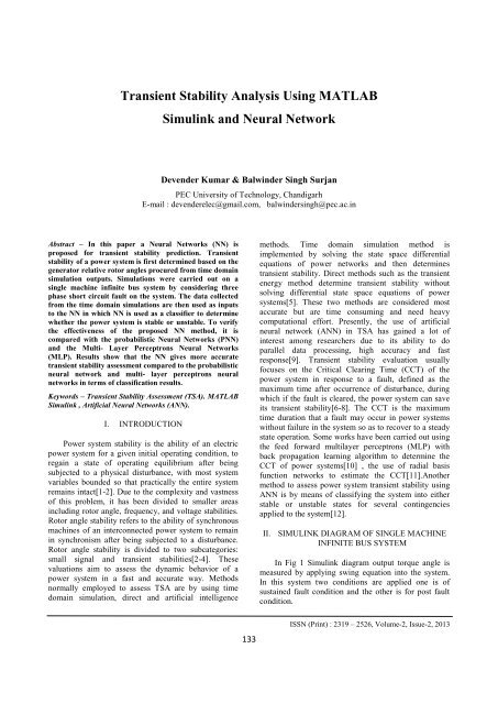
<strong>Transient</strong> <strong>Stability</strong> <strong>Analysis</strong> <strong>Using</strong> <strong>MATLAB</strong><strong>Simulink</strong> <strong>and</strong> Neural NetworkDevender Kumar & Balwinder Singh SurjanPEC University of Technology, Ch<strong>and</strong>igarhE-mail : devenderelec@gmail.com, balwindersingh@pec.ac.inAbstract – In this paper a Neural Networks (NN) isproposed for transient stability prediction. <strong>Transient</strong>stability of a power system is first determined based on thegenerator relative rotor angles procured from time domainsimulation outputs. Simulations were carried out on asingle machine infinite bus system by considering threephase short circuit fault on the system. The data collectedfrom the time domain simulations are then used as inputsto the NN in which NN is used as a classifier to determinewhether the power system is stable or unstable. To verifythe effectiveness of the proposed NN method, it iscompared with the probabilistic Neural Networks (PNN)<strong>and</strong> the Multi- Layer Perceptrons Neural Networks(MLP). Results show that the NN gives more accuratetransient stability assessment compared to the probabilisticneural network <strong>and</strong> multi- layer perceptrons neuralnetworks in terms of classification results.Keywords – <strong>Transient</strong> <strong>Stability</strong> Assessment (TSA). <strong>MATLAB</strong><strong>Simulink</strong> , Artificial Neural Networks (ANN).I. INTRODUCTIONPower system stability is the ability of an electricpower system for a given initial operating condition, toregain a state of operating equilibrium after beingsubjected to a physical disturbance, with most systemvariables bounded so that practically the entire systemremains intact[1-2]. Due to the complexity <strong>and</strong> vastnessof this problem, it has been divided to smaller areasincluding rotor angle, frequency, <strong>and</strong> voltage stabilities.Rotor angle stability refers to the ability of synchronousmachines of an interconnected power system to remainin synchronism after being subjected to a disturbance.Rotor angle stability is divided to two subcategories:small signal <strong>and</strong> transient stabilities[2-4]. Thesevaluations aim to assess the dynamic behavior of apower system in a fast <strong>and</strong> accurate way. Methodsnormally employed to assess TSA are by using timedomain simulation, direct <strong>and</strong> artificial intelligencemethods. Time domain simulation method isimplemented by solving the state space differentialequations of power networks <strong>and</strong> then determinestransient stability. Direct methods such as the transientenergy method determine transient stability withoutsolving differential state space equations of powersystems[5]. These two methods are considered mostaccurate but are time consuming <strong>and</strong> need heavycomputational effort. Presently, the use of artificialneural network (ANN) in TSA has gained a lot ofinterest among researchers due to its ability to doparallel data processing, high accuracy <strong>and</strong> fastresponse[9]. <strong>Transient</strong> stability evaluation usuallyfocuses on the Critical Clearing Time (CCT) of thepower system in response to a fault, defined as themaximum time after occurrence of disturbance, duringwhich if the fault is cleared, the power system can saveits transient stability[6-8]. The CCT is the maximumtime duration that a fault may occur in power systemswithout failure in the system so as to recover to a steadystate operation. Some works have been carried out usingthe feed forward multilayer perceptrons (MLP) withback propagation learning algorithm to determine theCCT of power systems[10] , the use of radial basisfunction networks to estimate the CCT[11].Anothermethod to assess power system transient stability usingANN is by means of classifying the system into eitherstable or unstable states for several contingenciesapplied to the system[12].II. SIMULINK DIAGRAM OF SINGLE MACHINEINFINITE BUS SYSTEMIn Fig 1 <strong>Simulink</strong> diagram output torque angle ismeasured by applying swing equation into the system.In this system two conditions are applied one is ofsustained fault condition <strong>and</strong> the other is for post faultcondition.133ISSN (Print) : 2319 – 2526, Volume-2, Issue-2, 2013
International Journal on Advanced Computer Theory <strong>and</strong> Engineering (IJACTE)In fig 3 torque angle response of the single machinesystem with various fault clearing time is shown. Thecritical clearing time of the system is 0.38sec., line 1 iswith fault clearing time of 0.49sec., this is the conditionfor sustained fault, means our system is suffering fromfault, the next line 2 is with fault clearing time of0.3sec., in response our system is out of the fault but dueto large fault clearing time it have more transients, thenext line 3 is with fault clearing time 0.2sec,Fig. 1 : <strong>Simulink</strong> model of single machine infinite bus systemWe can change from one condition to other condition byusing switch, <strong>and</strong> by varying the clock we can changethe fault clearing time of the system. As early we clearthe fault of the system the chances of attaining transientstability is more of the system. For stable operation ofthe system our torque angle should remain with limit..Fig. 2 : Angle v/s time relationship during post fault conditionFig 2 is when fault is cleared into the system <strong>and</strong>transients remain within the system after the clearing ofthe fault. If the fault clearing time is reduced of thesystem then our system would remain in stable state. Ifthe fault is cleared after critical clearing time them oursystem would no longer operate in stable state.in this response our torque angle is also above therequired limit, the next line 4 is with fault clearing timeof 0.1sec, this is the response where transients are verylow <strong>and</strong> our torque angle is within required limit.TABLE I output with fault clearing time of 0.10 sec.Accelerating power(Pa)angle0.288 21.640.539 24.210.439 31.59-4.46 37.65-0.63 38.92-0.66 38.64-0.56 36.40-0.327 29.850.04 22.440.435 16.250.50 13.10III. INTRODUCING DAMPING INTO THE SYSTEMBy introducing Damping into the system we canremove all the transients that are presented into thesystem after removing the fault of the system. Dampingcan be introduced into the system by providing anegative gain of very low value less than 1. Thisnegative feedback gain remove all the transients whichare present in the system.Fig 3 angle v/s time response of different fault clearing timeFig 4 Single machine infinite bus system with dampingISSN (PRINT) : 2320 – 8945, Volume -1, Issue -6, 2013134
International Journal on Advanced Computer Theory <strong>and</strong> Engineering (IJACTE)Fig 4 shows the smib system with damping, as wedecrease the value of negative gain it would decrease thetransient period, we can adjust gain as per ourrequirement. The output response with damping into thesystem is shown in the figure 5, it shows that thetransients are reduced to zero after 2-3 cycles, thisperiod can also be reduced by decreasing the value ofnegative feedback constant.Advantages:A neural network can perform tasks that a linearprogram can- not.When an element of the neural network fails, it cancontinue without any problem by their parallel nature.A neural network learns <strong>and</strong> does not need to bereprogrammed.It can be implemented in any application.It can be implemented without any problem.Disadvantages:The neural network needs training to operate.The architecture of a neural network is differentfrom the architecture of microprocessors therefore needsto be emulated.Requires high processing time for large neuralnetworks.Fig 5 ang v/s time response of smib system with dampingIV. NEURAL NETWORKA artificial neural network can be defined as amodel of reasoning based on the human brain. Thebrain consists of a densely interconnected set of nervecells, or basic information-processing units, calledneurons. An artificial neural network consists of anumber of very simple processors, also called neurons,which are analogous to the biological neurons in thebrain.Fig 6 Structure of biological neuronWhy would be necessary the implementation ofartificial neural networks? Although computing thesedays is truly advanced, there are certain tasks that aprogram made for a common microprocessor is unableto perform; even so a software implementation of aneural network can be made with their advantages <strong>and</strong>disadvantages.Application of neural networkCoEvolution of Neural Networks for Control ofPursuit & EvasionLearning the Distribution of Object Trajectories forEvent RecognitionRadiosity for Virtual Reality SystemsAutonomous Walker & Swimming EelRobocup: Robot World Cup<strong>Using</strong> HMM's for Audio-to-Visual ConversionArtificial Life: GalapagosSpeechreading (Lipreading)Detection <strong>and</strong> Tracking of Moving Targets Real-time Target Identification for SecurityApplicationsFacial AnimationAnother aspect of the artificial neural networks isthat there are different architectures, which consequentlyrequires different types of algorithms, but despite to bean apparently complex system, a neural network isrelatively simple. Artificial neural networks are amongthe newest signal processing technologies nowadays.The field of work is very interdisciplinary, but theexplanation I will give you here will be restricted to anengineering perspective. In the world of engineering,neural networks have two main functions: Patternclassifiers <strong>and</strong> as non- linear adaptive filters. As itsbiological predecessor, an artificial neural network is an135ISSN (PRINT) : 2320 – 8945, Volume -1, Issue -6, 2013
I n p u t S i g n a l sO u t p u t S i g n a l sInternational Journal on Advanced Computer Theory <strong>and</strong> Engineering (IJACTE)adaptive system. By adaptive, it means that eachparameter is changed during its operation <strong>and</strong> it isdeployed for solving the problem in matter. This iscalled the training phase.A artificial neural network is developed with asystematic step-by-step procedure which optimizes acriterion commonly known as the learning rule. Theinput/output training data is fundamental for thesenetworks as it conveys the information which isnecessary to discover the optimal operating point. Inaddition, a non- linear nature make neural networkprocessing elements a very flexible system.Input LayerMiddle LayerOutput LayerFig 7 Structure of Artificial neural networkThe neuron computes the weighted sum of the inputsignals <strong>and</strong> compares the result with a threshold value,. If the net input is less than the threshold, the neuronoutput is –1. But if the net input is greater than or equalto the threshold, the neuron becomes activated <strong>and</strong> itsoutput attains a value +1.X ix i w i1 1,if X Y 1,if X nThe neuron uses the following transfer or activationfunction. This type of activation function is called a signfunction.Fig 8 Possible active functions used in Neural NetworkV. TRAINING OF NEURAL NETWORKTraining to neural network small adjustments in theweights to reduce the difference between the actual <strong>and</strong>desired outputs of the perceptron. The initial weightsare r<strong>and</strong>omly assigned, usually in the range [0.5, 0.5],<strong>and</strong> then updated to obtain the output consistent with thetraining examples. It can be done by going to matlabnntoolbox.NN toolbox can be open by enteringcomm<strong>and</strong> >>nntool. It will open NN Network/ DataManager screen.Let P denote the input <strong>and</strong> T denote thetarget/output.In Matlab as per the guidelines of implementationthese are to be expressed in the form of matrices:T = [0 1 1 0]To use a network first design it, then train it beforestart simulation. We follow the steps in order to do theabove:Step-1: First we have to enter P <strong>and</strong> T to the NNNetwork Manager. This is done by clicking New Dataonce.Step-2: Type P as the Name, <strong>and</strong> corresponding matrixas the Value, select Inputs under Data Type, thenconfirm by clicking on Create.Step-3:Similarly, type in T as the Name, <strong>and</strong>corresponding matrix as the Value, select Targets, underData Type , then confirmStep-4: Now we try to create a Network. For this clickon New Network.Make Sure the parameters are as follows:Network Type = Feed forward – Back propTrain Function = TRAINLMAdaption Learning Function = LEARNGDMPerformance Function = MSENumbers of Layers = as per the requirementStep-5: Select Layer 1, type in 2 for the number ofneurons, & select TANSIG as Transfer Function.Select Layer 2, type in 1 for the number of neurons, &select TANSIG as Transfer Function.Step-6: Then, confirm by hitting the Create button,which concludes the network implementation phase.Step-7: Now, highlight Network with DOUBLE click,then click on Train button.Step-8: On Training Info, select P as Inputs, T asTargets.136ISSN (PRINT) : 2320 – 8945, Volume -1, Issue -6, 2013
International Journal on Advanced Computer Theory <strong>and</strong> Engineering (IJACTE)On Training Parameters, specify: epochs = 1000Goal = 0.000000000000001Max fail = 50After, confirming all the parameters have been specifiedas indented, hit Train Network.Fig 9 Training process of neural networkNow we can get following plots Performance plot, Itshould get a decaying plot (since you are trying tominimize the error).Training State PlotRegression PlotFig 11 Neural network implemented in smib system.Now for training this neural network according tothe output of our smib system, the output shown in table1 will be taken as the input to this neural network. Forthe better performance of neural our reference datashould be accurate. Output result with fault clearing0.1sec is the most accurate result available, so thisoutput result will be used for training the neuralnetwork. Neural network will obtain its final output bychanging its weight according to the requirement.Neural network is hit <strong>and</strong> trail method, it will improveits result iteration by iteration <strong>and</strong> when the final goal isreached it is finally trained. Untrained neural networkcan-not be used for the simulation purpose, training ofthe network is compulsory for its use.Fig 9 shows the training of neural network inmatlab, all the parameters should be within precise limitfor the better operation of the system, after the trainingof neural network is done, various plots for theperformance of neural network is shown, by seeingthese performance plot we are sure that our neuralnetwork is trained as per our requirement, shown in fig10, after verifying all the performance plot now we haveto implement this neural network in our smib system, bytaking power as input characteristic which control theoutput torque angle of the system, we can control theoutput performance of the smib by providing nueralnetwork into the system. The output response of thesystem with neural network <strong>and</strong> with time domainsolution is shown in fig 12 <strong>and</strong> fig 13.Fig10 Performance plot of neural networkFig 12 output response of smib system with neural network137ISSN (PRINT) : 2320 – 8945, Volume -1, Issue -6, 2013
International Journal on Advanced Computer Theory <strong>and</strong> Engineering (IJACTE)Fig 13 ang v/s time response of smib system with dampingwith neural network implemented in systemFig 12 shows that with same critical clearing timeour torque angle is limited to 50 degree in case of neuralnetwork as compare to 55 degree in case of time domainsolution. So nueral network can give better results whenused. Fig 13 shows the damping introduced into thesystem when neural network is implemented into thesystem. The results are even better in this case ascompared to time domain solutionVI. CONCLUSIONThe results shows that transient stability can becalculated with artificial neural network. The outputobtained from both the result are almost identical <strong>and</strong>best suited for transient stability stability analysis. Inthis paper smib system is simulated on matlab <strong>Simulink</strong><strong>and</strong> output generated from this <strong>Simulink</strong> work as theinput for neural network training <strong>and</strong> the result obtainedare compared. <strong>Transient</strong>s present in the system are alsobeen removed by providing damping into the system.VII. REFERENCES[1] P. kundur, j. paserba, v. ajjarapu, g. <strong>and</strong>erson, a.bose, c.canizares, n. hatziargyriou, d. hill, a.tankovic, c. taylor, t. v.cutsem, <strong>and</strong> v. vittal,“definition <strong>and</strong> classification of powersystemstability,” ieee trans. power syst., vol. 19,no. 3, pp. 1387–1401,aug. 2004.[2] N.amjady <strong>and</strong> s.f.majedi,2007, “transient stabilityprediction by a hybrid intelligent system”,ieeetransactions on power systems, vol 22, no. 3[3] P. kundur, “power system stability <strong>and</strong> control,”in the epri power system engineering series. newyork: mcgraw hill, 1994.[4] Z. racz <strong>and</strong> b. bokay, “power system stability”.new york: elsevierscience, 1988.[5] Noor izzri abdul wahab, azah mohamed <strong>and</strong> ainihussain, “an improved method in transientstability assessment of a power system usingprobabilistic neural network” journal of appliedsciences research, 3(11): 1267-1274, 2007[6] N. amjady <strong>and</strong> m. ehsan, “transient stabilityassessment of power systems by a new estimatingneural network,” can. j. elect. comp.eng., vol. 22,no. 3, pp. 131–137, jul. 1997.[7] C. w. liu, m. c. su, s. s. tsay, <strong>and</strong> y. j. wang,“application of a novel fuzzy neural network toreal-time transient stability swings predictionbased on synchronized phasor measurements,”ieee trans.power syst., vol. 14, no. 2, pp. 685–692, may 1999.[8] N. amjady, “application of a new artificial neuralnetwork in transient stability assessment,” inproc. ieee lescope conf., halifax, ns, canada, jun.1999, pp. 126–132.[10] Noor izzri abdul wahab, azah mohamed <strong>and</strong> ainihussain,, “an improved method in transientstability assessment of a power system usingprobabilistic neural network” journal of appliedsciences research, 3(11): 1267-1274, , 2007.[11] Sanyal, k. k., “transient stability assessment usingneural network”. ieee international conference onelectric utility deregulation, restructuring <strong>and</strong>power technologies, hong kong, 633-637, 2004.[12] Bettiol, a.l., a. souza, j.l. todesco, j. tesch, r jr.,“estimation of critical clearing times using neuralnetworks”. proc. ieee bologna power techconference, 3: 6, 2003.[13] Power system engineering Nagrath & Kothari,page no559-634, page no 981-988138ISSN (PRINT) : 2320 – 8945, Volume -1, Issue -6, 2013