Numerical study on plate anchor stability in clay
Numerical study on plate anchor stability in clay
Numerical study on plate anchor stability in clay

Create successful ePaper yourself
Turn your PDF publications into a flip-book with our unique Google optimized e-Paper software.
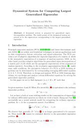
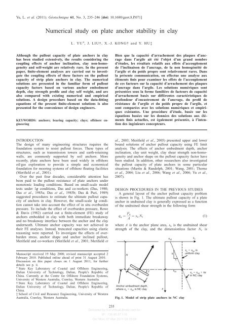
Yu, L. et al. (2011). Géotechnique 61, No. 3, 235–246 [doi: 10.1680/geot.8.P.071]<str<strong>on</strong>g>Numerical</str<strong>on</strong>g> <str<strong>on</strong>g>study</str<strong>on</strong>g> <strong>on</strong> <strong>plate</strong> <strong>anchor</strong> <strong>stability</strong> <strong>in</strong> <strong>clay</strong>L. YU , J. LIU†, X.-J. KONG† and Y. HU‡Although the pullout capacity of <strong>plate</strong> <strong>anchor</strong>s <strong>in</strong> <strong>clay</strong>has been studied extensively, the results c<strong>on</strong>sider<strong>in</strong>g thecoupl<strong>in</strong>g effects of <strong>anchor</strong> <strong>in</strong>cl<strong>in</strong>ati<strong>on</strong>, <strong>clay</strong> n<strong>on</strong>-homogeneityand self-weight are relatively rare. In the presentpaper, f<strong>in</strong>ite-element analyses are carried out to <strong>in</strong>vestigatethe coupl<strong>in</strong>g effects of these factors <strong>on</strong> the pulloutcapacity of strip <strong>plate</strong> <strong>anchor</strong>s <strong>in</strong> <strong>clay</strong>. The numericalsoluti<strong>on</strong>s are presented <strong>in</strong> the familiar form of pulloutcapacity factors based <strong>on</strong> various <strong>anchor</strong> embedmentdepth, <strong>clay</strong> strength profile and <strong>clay</strong> self weight, and arealso compared with exist<strong>in</strong>g numerical and empiricalsoluti<strong>on</strong>s. A design procedure based <strong>on</strong> the data-fitt<strong>in</strong>gequati<strong>on</strong>s of the present f<strong>in</strong>ite-element soluti<strong>on</strong>s is alsopresented for the c<strong>on</strong>venience of design eng<strong>in</strong>eers.KEYWORDS: <strong>anchor</strong>s; bear<strong>in</strong>g capacity; <strong>clay</strong>s; offshore eng<strong>in</strong>eer<strong>in</strong>gBien que la capacité d’arrachement des plaques d’ancragedans l’argile ait été l’objet d’un grand nombred’études, les résultats relatifs aux effets d’accouplementde l’<strong>in</strong>cl<strong>in</strong>ais<strong>on</strong> de l’ancrage, de la n<strong>on</strong> homogénéité del’argile et du poids propre s<strong>on</strong>t relativement rares. Dansla présente communicati<strong>on</strong>, <strong>on</strong> effectue une analyse auxéléments f<strong>in</strong>is pour exam<strong>in</strong>er les effets de l’accouplementde ces facteurs sur la capacité d’arrachement des plaquesd’ancrage dans l’argile. Les soluti<strong>on</strong>s numériques s<strong>on</strong>tprésentées sous la forme familière de facteurs de capacitéd’arrachement basés sur différentes caractéristiques deprof<strong>on</strong>deur d’encastrement de l’ancrage, du profil derésistance de l’argile et du poids propre de l’argile, ets<strong>on</strong>t comparées avec les soluti<strong>on</strong>s numériques et empiriquesexistantes. Une procédure d’étude, basée sur leséquati<strong>on</strong>s basées sur les d<strong>on</strong>nées des soluti<strong>on</strong>s aux élémentsf<strong>in</strong>is actuelles, est également présentée, à l’<strong>in</strong>tenti<strong>on</strong>des <strong>in</strong>génieurs c<strong>on</strong>cepteurs.INTRODUCTIONThe design of many eng<strong>in</strong>eer<strong>in</strong>g structures requires thefoundati<strong>on</strong> system to resist pullout forces. These types ofstructures, such as transmissi<strong>on</strong> towers and earth-reta<strong>in</strong><strong>in</strong>gwalls, are comm<strong>on</strong>ly supported by soil <strong>anchor</strong>s. Morerecently, <strong>plate</strong> <strong>anchor</strong>s have been used widely <strong>in</strong> offshoreoil/gas explorati<strong>on</strong> to provide a simple and ec<strong>on</strong>omicalfoundati<strong>on</strong> for moor<strong>in</strong>g systems of offshore float<strong>in</strong>g facilities(Merifield et al., 2001).Over the past four decades, c<strong>on</strong>siderable attenti<strong>on</strong> hasbeen paid to the pullout resistance of <strong>plate</strong> <strong>anchor</strong>s underm<strong>on</strong>ot<strong>on</strong>ic load<strong>in</strong>g c<strong>on</strong>diti<strong>on</strong>s. Based <strong>on</strong> small-scale modeltests under 1g c<strong>on</strong>diti<strong>on</strong>s, Das and co-workers (Das, 1980;Das et al., 1985a; Das et al., 1985b; Das & Puri, 1989)suggested procedures to estimate the ultimate pullout capacityof <strong>anchor</strong>s <strong>in</strong> <strong>clay</strong>. However, the small-scale 1g c<strong>on</strong>diti<strong>on</strong>cannot take <strong>in</strong>to account the effect of <strong>in</strong> situ overburdenpressure. To <strong>in</strong>clude the effect of overburden pressure, Rowe& Davis (1982) carried out a f<strong>in</strong>ite-element (FE) <str<strong>on</strong>g>study</str<strong>on</strong>g> of<strong>anchor</strong>s embedded <strong>in</strong> <strong>clay</strong> with both immediate breakawayand no breakaway <strong>in</strong>terface between the <strong>anchor</strong> and the <strong>clay</strong>underneath. Ultimate <strong>anchor</strong> capacity was not achieved <strong>in</strong>their FE analyses. Instead, truncated capacities us<strong>in</strong>g elasticreas<strong>on</strong><strong>in</strong>g were reported. To <strong>in</strong>vestigate the effects of overburdenstress, <strong>anchor</strong> shape and <strong>anchor</strong> <strong>in</strong>cl<strong>in</strong>ed pullout,Merifield and co-workers (Merifield et al., 2001; Merifield etal., 2003; Merifield et al., 2005) presented upper and lowerbound soluti<strong>on</strong>s of <strong>anchor</strong> pullout capacity us<strong>in</strong>g FE limitanalysis. The effects of <strong>anchor</strong> embedment depth, <strong>anchor</strong><strong>in</strong>cl<strong>in</strong>ati<strong>on</strong>, <strong>clay</strong> unit weight, <strong>clay</strong> shear strength n<strong>on</strong>-homogeneityand <strong>anchor</strong> shape <strong>on</strong> the pullout capacity factor havebeen studied. In additi<strong>on</strong>, other researchers also <strong>in</strong>vestigatedthe pullout capacity of <strong>plate</strong> <strong>anchor</strong>s <strong>in</strong> some particularsituati<strong>on</strong>s (Mart<strong>in</strong> & Randolph, 2001; Wang, 2001; Thorneet al., 2004; Liu et al., 2006; Wang et al., 2006; Yu et al.,2007).DESIGN PROCEDURES IN THE PREVIOUS STUDIESA general layout of the <strong>anchor</strong> pullout capacity problemis shown <strong>in</strong> Fig. 1. The ultimate pullout capacity of a <strong>plate</strong><strong>anchor</strong> <strong>in</strong> undra<strong>in</strong>ed <strong>clay</strong> is generally expressed as a functi<strong>on</strong>of the undra<strong>in</strong>ed shear strength <strong>in</strong> the follow<strong>in</strong>g formq u ¼ F uA ¼ s u N c (1)where A is the <strong>anchor</strong> plane area, s u is the undra<strong>in</strong>ed shearstrength of the <strong>clay</strong>, and the dimensi<strong>on</strong>less factor N c iss u0s uManuscript received 19 May 2008; revised manuscript accepted 2February 2010. Published <strong>on</strong>l<strong>in</strong>e ahead of pr<strong>in</strong>t 31 August 2010.Discussi<strong>on</strong> <strong>on</strong> this paper closes <strong>on</strong> 1 August 2011, for furtherdetails see p. ii. State Key Laboratory of Coastal and Offshore Eng<strong>in</strong>eer<strong>in</strong>g,Dalian University of Technology, Dalian, People’s Republic ofCh<strong>in</strong>a. Currently at the Centre for Offshore Foundati<strong>on</strong> Systems,University of Western Australia, Crawley, Western Australia.† State Key Laboratory of Coastal and Offshore Eng<strong>in</strong>eer<strong>in</strong>g,Dalian University of Technology, Dalian, People’s Republic ofCh<strong>in</strong>a.‡ School of Civil and Resource Eng<strong>in</strong>eer<strong>in</strong>g, University of WesternAustralia, Crawley, Western Australia.su suh <strong>in</strong>Hk uniform <strong>clay</strong>1βBAnchor embedment depth,where s s <strong>in</strong> NC <strong>clay</strong>uuhFig. 1. Model of strip <strong>plate</strong> <strong>anchor</strong>s <strong>in</strong> NC <strong>clay</strong>zs uhsu su0 kz<strong>in</strong> NC <strong>clay</strong>235Delivered by ICEVirtualLibrary.com to:IP: 130.95.57.110On: M<strong>on</strong>, 07 Mar 2011 03:15:09
236 YU, LIU, KONG AND HUusually referred to as the breakout/pullout capacity factor, ratio. However, the present <str<strong>on</strong>g>study</str<strong>on</strong>g> shows that the N cvalue ofwhich can be calculated froma shallowly embedded <strong>anchor</strong> is much lower than that of<strong>anchor</strong> roughness. Most of the available publicati<strong>on</strong>s providedthe N vertical sides. The soil doma<strong>in</strong> was def<strong>in</strong>ed <strong>in</strong> horiz<strong>on</strong>tal andc value of an <strong>anchor</strong> with very large embedment vertical dimensi<strong>on</strong>s as 20B for the cases of H/B ¼ 10 butN c ¼ F deeply embedded <strong>anchor</strong>. Moreover, the <strong>anchor</strong> <strong>in</strong>cl<strong>in</strong>ati<strong>on</strong>u(2) and <strong>clay</strong> n<strong>on</strong>-homogeneity also have significant effects <strong>on</strong>As uN c value of shallowly embedded <strong>anchor</strong>s. The ultimateFollow<strong>in</strong>g the term<strong>in</strong>ology of Rowe & Davis (1982), the bear<strong>in</strong>g factor of a very deep <strong>anchor</strong> is referred <strong>in</strong> theanalysis of <strong>anchor</strong> behaviour may be divided <strong>in</strong>to two present paper as the maximum ultimate bear<strong>in</strong>g capacitydist<strong>in</strong>ct categories, namely as ‘immediate breakaway – factor, N c,max .vented’ and ‘no breakaway – attached’ respectively. In the Step 4: for a n<strong>on</strong>-homogeneous <strong>clay</strong> profile, Merifield et‘immediate breakaway’ case the <strong>clay</strong>–<strong>anchor</strong> <strong>in</strong>terface separatesimmediately up<strong>on</strong> pullout acti<strong>on</strong>, so that a gap is freeto develop beh<strong>in</strong>d the <strong>anchor</strong>. This represents the case whereal. (2001) presented equati<strong>on</strong>s with the similar form to thefollow<strong>in</strong>g equati<strong>on</strong>s to calculate the weightless and ultimatepullout capacity factorsthere is no adhesi<strong>on</strong> or sucti<strong>on</strong> between the <strong>clay</strong> and <strong>anchor</strong>.NIn the ‘no breakaway’ case, the opposite is assumed, withc0,k6¼0 ¼ s k N c0,k¼0 (6)the <strong>clay</strong>–<strong>anchor</strong> <strong>in</strong>terface susta<strong>in</strong><strong>in</strong>g adequate tensi<strong>on</strong> to N c,k6¼0 ¼ s k N c,k¼0(7)ensure the <strong>anchor</strong> rema<strong>in</strong>s <strong>in</strong> c<strong>on</strong>tact with the <strong>clay</strong> at alltimes. In reality, it is likely that the true breakaway state of where s k and s k are def<strong>in</strong>ed <strong>in</strong> this paper as the soil n<strong>on</strong>homogeneityfactors to the <strong>anchor</strong> capacity factor <strong>in</strong> weight-an <strong>anchor</strong> will fall somewhere between the extremities ofthe immediate breakaway and no breakaway cases. The less uniform <strong>clay</strong> and to the ultimate <strong>anchor</strong> capacity factor<strong>anchor</strong> pullout capacity of the immediate breakaway case is <strong>in</strong> uniform <strong>clay</strong> respectively. Both s k and s kare functi<strong>on</strong>s ofalways applied for practical design because it is more embedment ratio (H/B) and degree of <strong>clay</strong> n<strong>on</strong>-homogeneity.c<strong>on</strong>servative when compared with the no breakaway case. In the <str<strong>on</strong>g>study</str<strong>on</strong>g> by Merifield et al. (2001) kB=s u0 was taken asFor a n<strong>on</strong>-homogeneous <strong>clay</strong> profile, the change <strong>in</strong> <strong>clay</strong> the degree of n<strong>on</strong>-homogeneity <strong>in</strong> the range ofshear strength with depth is assumed to vary l<strong>in</strong>early as kB=s u0 ¼ 0 . 1–1 . 0. However, for a practical <strong>clay</strong> strengths u ¼ s u0 þ kz (3)profile, as shown <strong>in</strong> Fig. 2(a), the upper bound and lowerbound of the <strong>clay</strong> shear strength are about s u ¼ 2 . 0+1 . 5zwhere s u0 is the undra<strong>in</strong>ed shear strength at the mud l<strong>in</strong>e, zis the depth below the mud l<strong>in</strong>e and k ¼ ds u =dz is thegradient of strength <strong>in</strong>creas<strong>in</strong>g with depth.Overall, the pullout capacity factor of a <strong>plate</strong> <strong>anchor</strong> <strong>in</strong>and 0 . 0+1 . 3z respectively. The <strong>clay</strong> n<strong>on</strong>-homogeneity ofthis practical case exceeds the <str<strong>on</strong>g>study</str<strong>on</strong>g> range of Merifield et al.(2001). For example, for a large <strong>anchor</strong> with 5 m <strong>anchor</strong>width, the <strong>clay</strong> strength at surface s u0 would be very low <strong>in</strong>the immediate breakaway case <strong>in</strong> <strong>clay</strong>, N c , is the functi<strong>on</strong> of offshore eng<strong>in</strong>eer<strong>in</strong>g. Thus kB=s u0 could be very large.<strong>anchor</strong> depth, <strong>anchor</strong> <strong>in</strong>cl<strong>in</strong>ati<strong>on</strong>, <strong>clay</strong> unit weight and the<strong>clay</strong> n<strong>on</strong>-homogeneity. A similar procedure was suggested <strong>in</strong>most of the exist<strong>in</strong>g publicati<strong>on</strong>s to obta<strong>in</strong> the pulloutcapacity of a <strong>plate</strong> <strong>anchor</strong> <strong>in</strong> <strong>clay</strong>. That procedure and theFurthermore, the <strong>anchor</strong> pullout capacity is determ<strong>in</strong>ed bythe <strong>clay</strong> <strong>in</strong> the vic<strong>in</strong>ity of the <strong>anchor</strong> rather than the <strong>clay</strong>close to the surface, especially for deeply embedded <strong>anchor</strong>s.Therefore, it could be more straightforward to take anotherattempts to improve it by the current FE <str<strong>on</strong>g>study</str<strong>on</strong>g> are described dimensi<strong>on</strong>less factor, kB=s uh , to describe the <strong>clay</strong> n<strong>on</strong>homogeneity,belowwhere s uh is the undra<strong>in</strong>ed shear strength ofStep 1: calculate the pullout capacity factor of the <strong>plate</strong><strong>anchor</strong> <strong>in</strong> weightless uniform <strong>clay</strong>, N c0,k¼0 . The representativethe <strong>clay</strong> at the <strong>anchor</strong> embedment depth.Therefore, the motivati<strong>on</strong>s of the present paper aresoluti<strong>on</strong>s of N c0,k¼0 were provided by Das (1980) us<strong>in</strong>g(a) to <strong>in</strong>vestigate the effect of <strong>anchor</strong> <strong>in</strong>cl<strong>in</strong>ati<strong>on</strong> andsmall-scale model tests, by Rowe & Davis (1982) us<strong>in</strong>g FEembedment depth <strong>on</strong> the ultimate pullout capacityanalyses and by Merifield et al. (2001) us<strong>in</strong>g numerical limitfactor, Nanalyses. The FE soluti<strong>on</strong>s of N c0,k¼0 will be presented andc(b) to <strong>in</strong>vestigate the effect of <strong>clay</strong> n<strong>on</strong>-homogeneity <strong>on</strong>compared with the previous results <strong>in</strong> this paper.NStep 2: for <strong>in</strong>cl<strong>in</strong>ed <strong>anchor</strong>s <strong>in</strong> weightless <strong>clay</strong>, the pulloutc0 and N c .capacity factor can be derived fromN c0, â6¼0 ¼ N c0, â¼08 þ ðN c0, â¼908The dimensi<strong>on</strong>less ratio of kB=s uh is taken as the <strong>clay</strong> n<strong>on</strong>homogeneityfactor <strong>in</strong> the present paper. Approximate equa- 2âN c0, â¼08 Þ(4) ti<strong>on</strong>s are presented to fit the FE results of pullout capacity908factors for various cases. Thus a design procedure based <strong>on</strong>the fitt<strong>in</strong>g equati<strong>on</strong>s is proposed to estimate the pulloutwhere â is the <strong>anchor</strong> <strong>in</strong>cl<strong>in</strong>ati<strong>on</strong> angle, as shown <strong>in</strong> Fig. 1.This equati<strong>on</strong> was proposed by Das & Puri (1989) and wasverified by Merifield et al. (2005). The current FE resultscapacity factor of a <strong>plate</strong> <strong>anchor</strong> with given depth, <strong>in</strong>cl<strong>in</strong>ati<strong>on</strong>,<strong>clay</strong> self-weight and <strong>clay</strong> strength profile <strong>in</strong> uniformand normally c<strong>on</strong>solidated (NC) <strong>clay</strong>.will show that equati<strong>on</strong> (4) is valid for pullout capacityfactors of vented <strong>plate</strong> <strong>anchor</strong>s <strong>in</strong> weightless soils, but notfor the cases when soil weight is <strong>in</strong>cluded, nor for the casesof attached <strong>plate</strong> <strong>anchor</strong>s.Step 3: with the assumpti<strong>on</strong> that the effects of <strong>clay</strong> unitweight and shear strength are <strong>in</strong>dependent of each other andmay be superimposed, the pullout capacity factor c<strong>on</strong>sider<strong>in</strong>g<strong>clay</strong> unit weight can be calculated fromFINITE-ELEMENT MODELSThe present numerical analyses were c<strong>on</strong>ducted by theAfena FE package (Carter & Balaam, 1995). The <strong>clay</strong> wassimulated by elasto-plastic model with Tresca failure criteri<strong>on</strong>.Poiss<strong>on</strong> ratio í ¼ 0 . 49 and fricti<strong>on</strong> and dilati<strong>on</strong> anglesj ¼ ł ¼ 0 were set to simulate the undra<strong>in</strong>ed c<strong>on</strong>diti<strong>on</strong>.N c ¼ N c0 þ ªH < N All of the FE calculati<strong>on</strong>s were based <strong>on</strong> six-nodedc(5) triangular elements with a three-po<strong>in</strong>t Gauss <strong>in</strong>tegrati<strong>on</strong> rules uhwhere N to calculate the element stiffness matrices. The analysescis the limit/ultimate pullout capacity factor forattached <strong>anchor</strong>s. The limit<strong>in</strong>g value of N assumed a perfectly rigid <strong>plate</strong> <strong>anchor</strong>, progressively displacedal<strong>on</strong>g the pullout directi<strong>on</strong>. A full fixity was appliedc for deeplyembedded <strong>anchor</strong>s is a functi<strong>on</strong> of the <strong>anchor</strong> geometry and at the base of the soil doma<strong>in</strong> and roller c<strong>on</strong>diti<strong>on</strong>s at itsDelivered by ICEVirtualLibrary.com to:IP: 130.95.57.110On: M<strong>on</strong>, 07 Mar 2011 03:15:09
NUMERICAL STUDY ON PLATE ANCHOR STABILITY IN CLAY 237s u : kPas u : kPa0 5 10 15 20 100 0 020 30 4012 4s u,CAUEDepth: m34su 0 1·3z8su 2 1·5z5Approximatel<strong>in</strong>ear relati<strong>on</strong>shipDepth: m6 12s u,CAUCs u,DSS7Vane 13Vane 358 16Vane 429 AverageApproximatel<strong>in</strong>ear relati<strong>on</strong>ship10 (a)20Fig. 2. Undra<strong>in</strong>ed shear strength of the <strong>clay</strong> from Gulf of Gu<strong>in</strong>ea (from NGI/COFS (2006)):(a) <strong>in</strong> situ vane tests; (b) laboratory test (CAUE, triaxial extensi<strong>on</strong>; CAUC, triaxial compressi<strong>on</strong>;DSS, simple shear)(b)10B for all the other cases. Calculati<strong>on</strong>s for a larger meshdoma<strong>in</strong> <strong>in</strong>dicated that extend<strong>in</strong>g the boundaries farther awayfrom the <strong>plate</strong> <strong>anchor</strong> did not <strong>in</strong>fluence the calculated limitresistance force. A typical model for a horiz<strong>on</strong>tal <strong>plate</strong><strong>anchor</strong> embedded at H/B ¼ 1.5 is shown <strong>in</strong> Fig. 3.The mesh close to the <strong>plate</strong> <strong>anchor</strong> is ref<strong>in</strong>ed. The meshdensity (h m<strong>in</strong> ) and the displacement <strong>in</strong>crement size (d i ) werechosen by the follow<strong>in</strong>g criteria given by Hu & Randolph(1998)h m<strong>in</strong>B ¼ 0 :01 (8) 0 : 8d i E kB¼ 0:17 (9)B s u s uhNodes of<strong>plate</strong> <strong>anchor</strong>Nodes ofsoil elementsNormal spr<strong>in</strong>gFig. 4. Sketch of nodal jo<strong>in</strong>t elementsShear sliderShearspr<strong>in</strong>gA numerical test shows that with further halv<strong>in</strong>g h m<strong>in</strong> and d igiven by equati<strong>on</strong>s (8) and (9) can <strong>on</strong>ly achieve a furtherc<strong>on</strong>vergence of not more than 0 . 2%, when the effective<strong>anchor</strong> breadth is extended by half of the size of theadjacent element to the <strong>anchor</strong> edge.Elasto-plastic nodal jo<strong>in</strong>t elements, which follow Herrmann’spr<strong>in</strong>ciple (Herrmann, 1978), were used to simulatethe soil–structure <strong>in</strong>teracti<strong>on</strong>. As shown <strong>in</strong> Fig. 4, a pair ofnodes is placed at the same <strong>in</strong>itial geometric locati<strong>on</strong>(separated <strong>in</strong> the figure for clarity). One stands for the rigidMesh ref<strong>in</strong>e z<strong>on</strong>e<strong>plate</strong> <strong>anchor</strong> and the other is the corresp<strong>on</strong>d<strong>in</strong>g node of theadjacent soil element. The node pair is l<strong>in</strong>ked with a normalspr<strong>in</strong>g and a shear spr<strong>in</strong>g. The stiffness of the normal spr<strong>in</strong>gwas set up with a very large value relative to the soilstiffness to avoid the penetrati<strong>on</strong> of the soil node <strong>in</strong>to the<strong>plate</strong>. For the vented (immediate breakaway) c<strong>on</strong>diti<strong>on</strong>, thenormal force of every nodal jo<strong>in</strong>t element will be checkedafter every calculati<strong>on</strong> step. If tensi<strong>on</strong> force occurs, thestiffness of the normal spr<strong>in</strong>g and the maximum shear forceof the slider are both set to zero and this is ma<strong>in</strong>ta<strong>in</strong>ed forall the follow<strong>in</strong>g calculati<strong>on</strong> steps. The maximum shearstrength of the shear slider, ô max , can be taken as ô max ¼ 0for smooth <strong>anchor</strong>s and ô max ¼ s u for rough <strong>anchor</strong>s, wheres u is the undra<strong>in</strong>ed shear strength of the adjacent soil.Smooth <strong>anchor</strong>s were analysed <strong>in</strong> this paper to providec<strong>on</strong>servative soluti<strong>on</strong>s. The effect of roughness <strong>on</strong> the<strong>anchor</strong> pullout capacity will be discussed briefly later.Fig. 3. Mesh detailsDisplacements applied <strong>on</strong>these nodesNUMERICAL RESULTS AND DISCUSSIONDef<strong>in</strong>iti<strong>on</strong> of failureFigure 5 shows the resp<strong>on</strong>ses of the <strong>anchor</strong> pulloutcapacity factor plotted aga<strong>in</strong>st its displacement for variouscases <strong>in</strong> weightless uniform <strong>clay</strong>s. For the cases withDelivered by ICEVirtualLibrary.com to:IP: 130.95.57.110On: M<strong>on</strong>, 07 Mar 2011 03:15:09
238 YU, LIU, KONG AND HU1412 β N cH/B 10, β 90°, vented10H/B 10, β 0°, vented86H/B 6, β 90°, ventedH/B 6, β 0°, vented42H/B 1, β 90°, ventedH/B 1, β 0°, vented00 200 400 600 800 1000 1200d E / BsFig. 5. Typical N c –pullout displacement curvestvented <strong>in</strong>terface, <strong>on</strong>ly shallowly embedded <strong>anchor</strong>s (H/B < 6) can reach limit pullout resistance before d t E/Bs u ¼ 100, where d t is the total displacement of the<strong>anchor</strong>. For the cases of H/B ¼ 10 (vented), N c cannotreach the limit value until d t E/Bs u ¼ 1000, where the <strong>clay</strong>failure mechanisms have just reached the <strong>clay</strong> surface, asshown <strong>in</strong> Fig. 6(b). For these deeply embedded <strong>anchor</strong>s <strong>in</strong>weightless <strong>clay</strong>s, the deformati<strong>on</strong> due to plastic flowbefore failure is so great that, for practical purposes,failure would be deemed to have occurred at a load wellbelow the collapse load. That is why Rowe & Davis(1982) def<strong>in</strong>ed the failure load as the load that would giverise to a displacement four times that predicted by anelastic analysis. However, for most deeply embedded <strong>anchor</strong>s<strong>in</strong> offshore eng<strong>in</strong>eer<strong>in</strong>g, the surcharge due to <strong>clay</strong>weight is quite large compared with the <strong>clay</strong> shearstrength (Wilde et al., 2001). This always ensures a fullylocalised <strong>clay</strong> flow mechanism and ‘attached’ c<strong>on</strong>diti<strong>on</strong>between <strong>anchor</strong> and <strong>clay</strong> when soil weight is relativelylarge (ª’H/s u . 6 . 4 for strip foot<strong>in</strong>g, S<strong>on</strong>g et al. (2008)).Whereas for attached cases, N c can reach the limit valuevery quickly for all the embedment ratios with any pulloutangles (<strong>on</strong>ly H/B ¼ 10, â ¼ 08 was plotted <strong>in</strong> Fig. 5). Inthis paper, the pullout capacity factors of weightless <strong>clay</strong>sare supposed to provide N c0 values (pullout capacity factor<strong>in</strong> weightless <strong>clay</strong>) for equati<strong>on</strong> (5). S<strong>in</strong>ce soil weightcannot be ignored <strong>in</strong> most offshore practices ow<strong>in</strong>g to thelarge <strong>anchor</strong> size and deep embedment, the ultimate values<strong>in</strong> the N c –displacement curves were selected as the breakoutfactors. Furthermore, this can ensure fully developedsoil failure mechanisms.The pullout capacity factors of strip <strong>anchor</strong>s <strong>in</strong> weightlessuniform <strong>clay</strong>The pullout capacity factors of strip <strong>anchor</strong>s <strong>in</strong> uniform<strong>clay</strong> (s u ¼ 20 kPa, ª ¼ 0) are calculated first and the resultsare presented <strong>in</strong> Fig. 7. The FE results of Rowe & Davis(1982) and the numerical limit soluti<strong>on</strong>s of Merifield et al.(2001) are also presented for comparis<strong>on</strong>. It can be seen thatfor the cases with attached bases (no breakaway), N c of bothhoriz<strong>on</strong>tal and vertical <strong>plate</strong> <strong>anchor</strong>s agree well with theresults of Rowe & Davis (1982). The current N c of ahoriz<strong>on</strong>tal <strong>plate</strong> <strong>anchor</strong> reaches the limit value ofN c,max ¼ 11 .59 when H/B > 3, which is very close to thesoluti<strong>on</strong> of N c,max ¼ 11. 42 by Rowe & Davis (1982).For the cases with vented bases (immediate breakaway),the current N c0 values fall favourably <strong>in</strong> the range of theupper and lower bound soluti<strong>on</strong>s from H/B ¼ 1–10. Noteu7γ 8 2·5, 5, 7·5 and 10 10(a)7γ 8 2·5, 5, 7·5 and 10 10(b)Fig. 6. Soil collapse mechanisms as depicted by arrows of nodaldisplacement <strong>in</strong>crements and c<strong>on</strong>tours of the octahedral shearstra<strong>in</strong> <strong>in</strong>crement (ª 8 ) for H/B 10 <strong>in</strong> uniform weightless soil:(a) d t E=Bs u 100; (b) d t E=Bs u 1000that the current FE results are a little lower than the upperbound soluti<strong>on</strong>s when the <strong>anchor</strong> is deeply embedded. Thismight be because of the much denser mesh (h m<strong>in</strong> /B , 0 . 01here but h m<strong>in</strong> /B ¼ 0 . 125 <strong>in</strong> Merifield et al. (2001)) used <strong>in</strong>the current paper.For vented <strong>anchor</strong>s with small embedment ratios (H/B , 3), all results by current FE analysis, Rowe & Davis(1982) and Merifield et al. (2001) stay closely together.However, for the vented <strong>anchor</strong>s with large embedmentratios (H/B . 3), the soluti<strong>on</strong>s of Rowe & Davis (1982)appear much lower than the other results. This might bema<strong>in</strong>ly due to the truncati<strong>on</strong> criteri<strong>on</strong> applied <strong>in</strong> Rowe andDavis’ analysis, whereas the ultimate failure capacity wasselected <strong>in</strong> the current FE analysis. The current FE resultsagree well with the soluti<strong>on</strong>s by Merifield et al. (2001),s<strong>in</strong>ce the limit analysis provides the ultimate capacities ofthe <strong>anchor</strong>s by us<strong>in</strong>g rigid plasticity.The effect of <strong>anchor</strong> <strong>in</strong>cl<strong>in</strong>ati<strong>on</strong> <strong>on</strong> the pullout capacityfactors of vented <strong>anchor</strong>s <strong>in</strong> weightless <strong>clay</strong>Figure 8 shows the pullout capacity factors of vented <strong>plate</strong><strong>anchor</strong>s with various <strong>in</strong>cl<strong>in</strong>ati<strong>on</strong>s <strong>in</strong> weightless uniformDelivered by ICEVirtualLibrary.com to:IP: 130.95.57.110On: M<strong>on</strong>, 07 Mar 2011 03:15:09
N cN c14121086420114121086420122334455H/B(a)H/B(b)66Attached, current FE <str<strong>on</strong>g>study</str<strong>on</strong>g>Attached, FE (Rowe & Davis, 1982)Vented, current FE <str<strong>on</strong>g>study</str<strong>on</strong>g>Vented, UB (Merifield et al., 2001)Vented, LB (Merifield et al., 2001)Vented, FE (Rowe & Davis, 1982)77HB8N* c,max 11·598B9910N*c,max 11·59Fig. 7. Comparis<strong>on</strong> of the bear<strong>in</strong>g capacity factors for <strong>plate</strong><strong>anchor</strong>s <strong>in</strong> weightless uniform <strong>clay</strong>: (a) horiz<strong>on</strong>tal <strong>anchor</strong>;(b) vertical <strong>anchor</strong>N c09876543210NUMERICAL STUDY ON PLATE ANCHOR STABILITY IN CLAY 239β 90° (vertical), 67·5 ° , 45°,22·5° and 0° (horiz<strong>on</strong>tal)1 2 3 4 5 6 7 8 9 10H/BFig. 8. Effect of <strong>in</strong>cl<strong>in</strong>ati<strong>on</strong> <strong>on</strong> N c of vented <strong>anchor</strong>s <strong>in</strong> uniformweightless <strong>clay</strong>sH10<strong>clay</strong>s. At all embedment ratios, the pullout capacity factorN c0 is the highest for the vertical <strong>anchor</strong> and lowest for thehoriz<strong>on</strong>tal <strong>anchor</strong>. The soil displacement <strong>in</strong>crements atH=B ¼ 1 are shown <strong>in</strong> Fig. 9. The dashed l<strong>in</strong>es, which wereformed accord<strong>in</strong>g to the c<strong>on</strong>tours of the maximum shearstra<strong>in</strong> <strong>in</strong> the octahedral plane, show the approximate shearslip planes. The shear c<strong>on</strong>tours are not plotted for clarity. Itcan be seen that shear failure occurs <strong>on</strong>ly <strong>in</strong> fr<strong>on</strong>t of the<strong>plate</strong> <strong>anchor</strong> but not beh<strong>in</strong>d, ow<strong>in</strong>g to the vented c<strong>on</strong>diti<strong>on</strong>.For the horiz<strong>on</strong>tal <strong>anchor</strong>, the <strong>clay</strong> failure develops verticallyfrom both <strong>anchor</strong> edges to the surface (Fig. 9(a)). For thevertical <strong>anchor</strong>, the length of total <strong>clay</strong> shear failure planesis obviously greater than that for the horiz<strong>on</strong>tal <strong>anchor</strong>. Thisresults <strong>in</strong> the N c0 of the vertical <strong>anchor</strong> be<strong>in</strong>g higher thanthat of the horiz<strong>on</strong>tal <strong>anchor</strong> at H/B ¼ 1 <strong>in</strong> weightless uniform<strong>clay</strong>. The soil flow mechanisms for rough <strong>anchor</strong>s arealso depicted <strong>in</strong> Fig. 9. The effect of <strong>anchor</strong> roughness willbe discussed later.A simple relati<strong>on</strong>ship to estimate the capacity of <strong>in</strong>cl<strong>in</strong>ed<strong>anchor</strong>s, as shown <strong>in</strong> equati<strong>on</strong> (4), has been proposed byDas & Puri (1989) and c<strong>on</strong>firmed by Merifield et al.(2005). This equati<strong>on</strong> is also valid for the current FEresults.The values of the pullout capacity factors of horiz<strong>on</strong>taland vertical <strong>plate</strong> <strong>anchor</strong>s <strong>in</strong> weightless uniform <strong>clay</strong> can beapproximated by the follow<strong>in</strong>g equati<strong>on</strong>sN c0, â¼08,k¼0 ¼ 2:483ln ðH=BÞþ 1:974R 2 ¼ 0:9999N c0, â¼908,k¼0 ¼ 2:174ln ðH=BÞþ 3:391R 2 ¼ 0:9999(10)Thus, the pullout capacity factor of a strip <strong>plate</strong> <strong>anchor</strong>embedded at any depth and any <strong>in</strong>cl<strong>in</strong>ati<strong>on</strong> <strong>in</strong> weightlessuniform <strong>clay</strong> can be calculated by equati<strong>on</strong>s (10) and (4).The effect of overburden pressureThe exist<strong>in</strong>g publicati<strong>on</strong>s (Rowe & Davis, 1982;Merifield et al., 2001) show that the N c of a <strong>plate</strong> <strong>anchor</strong><strong>in</strong>creases l<strong>in</strong>early with the dimensi<strong>on</strong>less overburden pressure,ªH=s u , but rema<strong>in</strong>s not larger than the ultimatepullout capacity factor N c , as shown <strong>in</strong> equati<strong>on</strong> (5). Bothof the publicati<strong>on</strong>s gave <strong>on</strong>ly a limit value of N c for<strong>anchor</strong>s at very deep embedment ratios. In expand<strong>in</strong>g theirresults, the effects of <strong>clay</strong> self-weight <strong>on</strong> <strong>plate</strong> <strong>anchor</strong>s both<strong>in</strong> uniform and <strong>in</strong> NC <strong>clay</strong>s are calculated <strong>in</strong> this paper.Only the cases <strong>in</strong> NC <strong>clay</strong> are presented <strong>in</strong> Fig. 10. Thecurrent FE results show that the assumpti<strong>on</strong> of superimpositi<strong>on</strong>of the overburden pressure is also valid <strong>in</strong> NC <strong>clay</strong>;however, the ultimate limit pullout capacity factor N cvaries severely with <strong>anchor</strong> embedment ratios and <strong>in</strong>cl<strong>in</strong>ati<strong>on</strong>s<strong>in</strong> NC <strong>clay</strong>.Once the <strong>clay</strong> self-weight is <strong>in</strong>cluded <strong>in</strong> the <strong>anchor</strong> analysis,the soil flow around the <strong>anchor</strong> becomes localised at arather shallow embedment. At the same time, the soiladjacent to the <strong>anchor</strong> base is attached to the <strong>anchor</strong> withouta gap form<strong>in</strong>g beneath it. This is due to the overburdenpressure generated from the soil weight and act<strong>in</strong>g at the<strong>anchor</strong> base. The current FE results show that, for <strong>plate</strong><strong>anchor</strong>s at any embedment ratio with any <strong>in</strong>cl<strong>in</strong>ati<strong>on</strong> angle,the ultimate pullout capacity factors of vented <strong>anchor</strong>s withvery large overburden stress ratios of ªH=s uh are almostidentical to those of attached <strong>anchor</strong>s, <strong>on</strong>ly with a m<strong>in</strong>imaldifference of less than 0.5% due to computer round-offerrors. For attached <strong>plate</strong> <strong>anchor</strong>s, the <strong>clay</strong> weight (or overburdenstress) has no effect <strong>on</strong> the pullout capacity, s<strong>in</strong>ceDelivered by ICEVirtualLibrary.com to:IP: 130.95.57.110On: M<strong>on</strong>, 07 Mar 2011 03:15:09
240 YU, LIU, KONG AND HUβ 0°β 45°(a)β 90°β 0°β 45°(b)β 90°Fig. 9. Flow mechanisms of the soil around the <strong>plate</strong> <strong>anchor</strong>s with vented bases <strong>in</strong> weightless uniform <strong>clay</strong> (H/B 1):(a) smooth <strong>in</strong>terface; (b) rough <strong>in</strong>terface12108N c 61:1N c 642H/B 1, 3, 1000 1 2 3 4 5 6 7γH/s uh(a)121084200121:1H/B 1, 3, 4, 6, 10345γH/s uh(b)Fig. 10. Effect of overburden pressure (s u 1+2z kPa): (a) â 08;(b) â 90867HB88B9H91010the <strong>clay</strong> weight does not change the soil flow mechanismaround the <strong>anchor</strong>. Thus there are two ways to obta<strong>in</strong> theultimate pullout capacity factor N c : vented <strong>anchor</strong> with alarge overburden stress ratio of ªH=s uh , or, attached <strong>anchor</strong>with or without <strong>clay</strong> weight. Under these two scenarios, the<strong>clay</strong>s are both attached to the <strong>anchor</strong> bases and the N cvalues should be identical.The ultimate pullout capacity factors (N c ) of <strong>plate</strong> <strong>anchor</strong>sat various embedment ratios <strong>in</strong> uniform and NC <strong>clay</strong>sare plotted <strong>in</strong> Fig. 11. A vented base was assumed here andthe overburden stress ratio was taken as ªH=s uh ¼ 10, whichwas large enough to ensure a fully localised <strong>clay</strong> flowmechanism. It can be seen from Fig. 11(a) that all of thepullout capacity factors reach a limit value of 11 . 59 at theembedment ratio of H/B > 3. This limit value was def<strong>in</strong>edas the maximum ultimate pullout capacity factor (N c,max )<strong>in</strong>this paper. Exact soluti<strong>on</strong>s for deeply embedded (<strong>in</strong>f<strong>in</strong>itelyth<strong>in</strong>) circular <strong>plate</strong>s range from 12 . 42 for a smooth <strong>in</strong>terfaceto 13 . 11 for a rough <strong>in</strong>terface (Mart<strong>in</strong> & Randolph, 2001).The corresp<strong>on</strong>d<strong>in</strong>g soluti<strong>on</strong> for a smooth strip <strong>anchor</strong> is11.42 for the FE result by Rowe & Davis (1982), 11.16 forlower bound and 11 . 86 for upper bound by Merifield et al.(2001). The N c,max ¼ 11 .59 by the current FE analysis fallswith<strong>in</strong> the range of exist<strong>in</strong>g soluti<strong>on</strong>s.It can also be seen from Fig. 11(a) that the N cvalues ofshallowly embedded <strong>anchor</strong>s (H/B , 3) <strong>in</strong>crease with <strong>in</strong>creas<strong>in</strong>gembedment ratio H/B and decrease with <strong>in</strong>creas<strong>in</strong>g<strong>anchor</strong> <strong>in</strong>cl<strong>in</strong>ati<strong>on</strong> angle â. These variati<strong>on</strong>s have similartrends and become more profound <strong>in</strong> NC <strong>clay</strong>, as shown <strong>in</strong>Fig. 11(b). For vertical <strong>plate</strong> <strong>anchor</strong>s <strong>in</strong> NC <strong>clay</strong> (â ¼ 908 <strong>in</strong>Fig. 11(b)), the ultimate pullout capacity factor varies fromN c ¼ 4. 88 at H/B ¼ 1 to N c ¼ 11. 01 at H/B ¼ 10. Themaximum ultimate pullout capacity factor <strong>in</strong> this NC <strong>clay</strong>(s u ¼ 0 . 1+3z kPa) is also N c,max ¼ 11. 59.The values of the ultimate pullout capacity factors of <strong>plate</strong><strong>anchor</strong>s <strong>in</strong> uniform <strong>clay</strong>s can be fitted by the follow<strong>in</strong>gexpressi<strong>on</strong>sDelivered by ICEVirtualLibrary.com to:IP: 130.95.57.110On: M<strong>on</strong>, 07 Mar 2011 03:15:09
1412108N * c642011412108N * c6422N* c,max 11·59β 0° (horiz<strong>on</strong>tal), 22·5°, 45°, 67·5°, 90° (vertical)34NUMERICAL STUDY ON PLATE ANCHOR STABILITY IN CLAY 2415H/B(a)6N* c,max 11·59 for β 0°N*c 11·01 for H / B 10, β 90°β 0° (horiz<strong>on</strong>tal), 22·5°, 45°, 67·5°, 90° (vertical)78910Note that equati<strong>on</strong> (12) is different from equati<strong>on</strong> (4) <strong>on</strong> theright-hand side.In both uniform and NC <strong>clay</strong>s, the ultimate <strong>anchor</strong> pulloutcapacity factor N cis the highest for a horiz<strong>on</strong>tal <strong>plate</strong>and lowest for a vertical <strong>plate</strong>. This trend is opposite to theresults <strong>in</strong> weightless <strong>clay</strong> presented above (Fig. 8). The soilflow mechanisms of shallow <strong>plate</strong> <strong>anchor</strong>s (H/B ¼ 1) <strong>in</strong>uniform <strong>clay</strong> with ªH=s uh ¼ 10 are shown <strong>in</strong> Fig. 12. Itcan be seen that the soil failure planes of a horiz<strong>on</strong>tal<strong>anchor</strong> (Fig. 12(a)) develop deeply <strong>in</strong>to the <strong>clay</strong> and thelength of failure planes is l<strong>on</strong>ger than those of a vertical<strong>anchor</strong> (Fig. 12(b)). This is why the ultimate pulloutcapacity factor of a horiz<strong>on</strong>tal <strong>anchor</strong> is larger than that ofa vertical <strong>anchor</strong>.The soil flow mechanisms of deeply embedded <strong>anchor</strong>swith attached bases are depicted by the octahedral shearstra<strong>in</strong> <strong>in</strong>crements <strong>in</strong> Fig. 13. In uniform <strong>clay</strong>, the flowmechanism of â ¼ 08 (Fig. 13(a)) is almost identical withthat of â ¼ 908 (Fig. 13(b)), except rotated by 908. Thisc<strong>on</strong>firms that the ultimate pullout capacity factors are thesame for horiz<strong>on</strong>tal and vertical <strong>plate</strong> <strong>anchor</strong>s with H/B > 3<strong>in</strong> uniform <strong>clay</strong>, as shown <strong>in</strong> Fig. 11(a). Whereas, <strong>in</strong> NC<strong>clay</strong>, the flow mechanism of â ¼ 08 is almost the same asthat <strong>in</strong> uniform <strong>clay</strong>. However, for an <strong>anchor</strong> with â ¼ 908 <strong>in</strong>NC <strong>clay</strong>, although the flow mechanism is still localised(without reach<strong>in</strong>g the soil surface), it is obviously asymmetricalto the <strong>anchor</strong> pullout directi<strong>on</strong> and c<strong>on</strong>centrates <strong>on</strong> theupper side of the <strong>plate</strong> <strong>anchor</strong>, s<strong>in</strong>ce the soil is weaker atshallower depth. This is why the N cvalue for an <strong>anchor</strong>with â ¼ 08 is higher than that for an <strong>anchor</strong> with â ¼ 908<strong>in</strong> NC <strong>clay</strong>, as shown <strong>in</strong> Fig. 11(b).0123N c, â¼08,k¼0 ¼ 2 :90ðH=BÞþ 6:02 < N c,max ¼ 11 :59R 2 ¼ 0:9999N c, â¼908,k¼0 ¼ 2 :72ðH=BÞþ 4:02 < N c,max ¼ 11 :59R 2 ¼ 0:999745H/B(b)Fig. 11. Ultimate pullout capacity factors N c<strong>in</strong> <strong>clay</strong>: (a) <strong>in</strong>uniform <strong>clay</strong>; (b) <strong>in</strong> NC <strong>clay</strong> (s u 0.1 +3z kPa)(11)The N c of an <strong>in</strong>cl<strong>in</strong>ed <strong>plate</strong> <strong>anchor</strong> can be calculated fromN c, â ¼ N c, â¼908 þ N c, â¼08N 2908 âc, â¼908908(12)678910The effect of <strong>clay</strong> n<strong>on</strong>-homogeneity <strong>on</strong> the <strong>anchor</strong> pulloutcapacity factorAs discussed <strong>in</strong> the <strong>in</strong>troducti<strong>on</strong>, the dimensi<strong>on</strong>less ratioof kB=s uh is taken <strong>in</strong> this paper as the degree of <strong>clay</strong> n<strong>on</strong>homogeneity,where s uh is the undra<strong>in</strong>ed shear strength of<strong>clay</strong> at the <strong>anchor</strong> embedment depth, as shown <strong>in</strong> Fig. 1.When <str<strong>on</strong>g>study</str<strong>on</strong>g><strong>in</strong>g the effect of <strong>clay</strong> n<strong>on</strong>-homogeneity, s uh waskept c<strong>on</strong>stant. The <strong>in</strong>crease <strong>in</strong> kB=s uh was realised by <strong>in</strong>creas<strong>in</strong>gthe gradient of soil strength k. The range of the<strong>clay</strong> n<strong>on</strong>-homogeneity kB=s uh is from uniform <strong>clay</strong> to NC<strong>clay</strong> of s u ¼ 0 . 1+3z kPa, which covers the practical range <strong>in</strong>geotechnical design.The effect of kB/s uh <strong>on</strong> N c0 . Start<strong>in</strong>g from uniform <strong>clay</strong>, the<strong>in</strong>crease of <strong>clay</strong> n<strong>on</strong>-homogeneity, kB=s uh , will enlarge thereducti<strong>on</strong> of the shear strength of the <strong>clay</strong> above the <strong>anchor</strong>embedment depth and also enlarge the <strong>in</strong>crement of the shearstrength of the <strong>clay</strong> below the <strong>anchor</strong> embedment depth. Inweightless <strong>clay</strong>, <strong>on</strong>ly the <strong>clay</strong> <strong>in</strong> fr<strong>on</strong>t of the <strong>plate</strong> <strong>anchor</strong> failsand flows plastically. The <strong>clay</strong> failure planes develop from the<strong>anchor</strong> edges to the <strong>clay</strong> surface, as shown <strong>in</strong> Fig. 9.Therefore, it is expected that the <strong>clay</strong> n<strong>on</strong>-homogeneitywould decrease the pullout capacity factor of a vented <strong>plate</strong>Anchor embedmentdepth level(a)Anchor embedmentdepth level(b)Fig. 12. Soil flow mechanisms of shallowly embedded <strong>plate</strong> <strong>anchor</strong>s with attached bases (H/B 1):(a) â 08; (b) â 908Delivered by ICEVirtualLibrary.com to:IP: 130.95.57.110On: M<strong>on</strong>, 07 Mar 2011 03:15:09
242 YU, LIU, KONG AND HU1·1γ 81·0(a)0·00050·00040·0003s k N ckN c00·90·80·70·6H/B 1, 1·5, 2, 3, 4, 6, 10HB0·50·400·20·40·60·81·0kB/s uh(a)1·11·0H/B 1, 1·5, 2, 3, 4, 6, 100·9H(b)(c)s k N ckN c00·8BFig. 13. Soil flow mechanisms of deeply embedded <strong>plate</strong> <strong>anchor</strong>swith attached bases (H/B 6, depicted by the shear stra<strong>in</strong><strong>in</strong>crement <strong>in</strong> the octahedral plane, ª 8 ): (a) â 08, kB/s uh 0 (orkB/s uh 0.17); (b) â 908, kB/s uh 0; (c) â 908, kB/s uh 0.17<strong>anchor</strong> <strong>in</strong> weightless <strong>clay</strong>. Here a n<strong>on</strong>-homogeneity factor, s k ,is def<strong>in</strong>ed to express the effect of <strong>clay</strong> n<strong>on</strong>-homogeneity <strong>on</strong>the <strong>anchor</strong> pullout capacity factor <strong>in</strong> weightless <strong>clay</strong>0·70·600·20·4 0·6kB/s uh(b)Fig. 14. Effect of soil n<strong>on</strong>-homogeneity <strong>on</strong> the bear<strong>in</strong>g capacityfactors of <strong>plate</strong> <strong>anchor</strong>s <strong>in</strong> weightless soil: (a) horiz<strong>on</strong>tal<strong>anchor</strong>; (b) vertical <strong>anchor</strong>0·81·0s k ¼ N c0,k6¼0(13)kBN c0,k¼0s k, â¼908 ¼ 1 f 90s uhfwhere N c0 is the pullout capacity factor of the <strong>plate</strong> <strong>anchor</strong>90 ¼ 0:68H 0 : 50:41 when H BB , 4 (15)<strong>in</strong> weightless <strong>clay</strong>.Figure 14 shows the relati<strong>on</strong>ship between s k and kB=s uh f 90 ¼ 0:153 H for horiz<strong>on</strong>tal and vertical <strong>plate</strong> <strong>anchor</strong>s at various embedmentratios. It can be seen that for the horiz<strong>on</strong>tal <strong>anchor</strong> atB þ 0 :341 when H B > 4where the maximum difference between sany embedment ratios (Fig. 14(a)), s k decreases l<strong>in</strong>early withk, â¼908 by thisequati<strong>on</strong> and that by the FE analysis is also less than 1<strong>in</strong>creas<strong>in</strong>g kB=s uh . The gradient of the l<strong>in</strong>ear relati<strong>on</strong>ship is. 4%.a functi<strong>on</strong> of <strong>anchor</strong> embedment ratio, H/B. The <strong>clay</strong> n<strong>on</strong>homogeneityfactor of a horiz<strong>on</strong>tal <strong>plate</strong> <strong>anchor</strong> <strong>in</strong> weightless<strong>clay</strong>, s k, â¼08 , can be approximately expressed by theuh <strong>on</strong> N c . Similar to the def<strong>in</strong>iti<strong>on</strong> of s kThe effect of kB/sdescribed above, a n<strong>on</strong>-homogeneity factor of the ultimatefollow<strong>in</strong>g equati<strong>on</strong>spullout capacity factor is def<strong>in</strong>ed askBs k, â¼08 ¼ 1 f 0ss uhk ¼ N c,k6¼0N (16)c,k¼0f 0 ¼ 1:77H 0 : 31:289 when H BB , 4 (14) where N cis the ultimate pullout capacity factor.For the cases with high overburden stress ratios, the <strong>clay</strong>f 0 ¼ 0:192 H B þ 0 :644 when H beh<strong>in</strong>d the vented <strong>plate</strong> <strong>anchor</strong>s would flow together with theB > 4 <strong>anchor</strong> similar to the cases of attached <strong>anchor</strong>s. Thus <strong>clay</strong>s <strong>on</strong>both sides of the <strong>anchor</strong> c<strong>on</strong>tribute to the <strong>anchor</strong> pulloutcapacity. Whether s k is less or more than 1 . 0 depends <strong>on</strong>where the maximum difference between the s k, â¼08 soluti<strong>on</strong> which part of the <strong>clay</strong> (over or under the <strong>anchor</strong> embedmentby this equati<strong>on</strong> and that by the FE analysis is less than depth) c<strong>on</strong>tributes more to the pullout capacity. For a shallowly1.4%.embedded horiz<strong>on</strong>tal <strong>plate</strong> <strong>anchor</strong>, for example H/B ¼ 1 withFor a vertical <strong>anchor</strong>, the relati<strong>on</strong>ship between s k,â¼908 â ¼ 08, the total length of the <strong>clay</strong> failure planes below theand kB=s uh is shown <strong>in</strong> Fig. 14(b). By apply<strong>in</strong>g l<strong>in</strong>ear <strong>anchor</strong> embedment depth is l<strong>on</strong>ger than that above the <strong>anchor</strong>functi<strong>on</strong>s, the follow<strong>in</strong>g equati<strong>on</strong> can be used to calculate embedment depth (Fig. 12(a)). This means, for this case, thes k, â¼908 <strong>clay</strong> n<strong>on</strong>-homogeneity would have a positive effect <strong>on</strong> theDelivered by ICEVirtualLibrary.com to:IP: 130.95.57.110On: M<strong>on</strong>, 07 Mar 2011 03:15:09
******NUMERICAL STUDY ON PLATE ANCHOR STABILITY IN CLAY 243ultimate pullout capacity factor. The FE results of s kareshown <strong>in</strong> Fig. 15(a). As expected, s where the maximum error between equati<strong>on</strong> predicti<strong>on</strong>s andk . 1. 0 for H/B ¼ 1 and the FE results is less than 2 . 1%. For vertical <strong>anchor</strong>s1.5 with â ¼ 08. For the case of H/B ¼ 2, the <strong>in</strong>crease ofkB=s uh has little effect <strong>on</strong> N c before kB=s uh ¼ 0 . 2, but has anobvious negative effect when kB=s uh . 0 . s k,â¼908 ¼ 1 f kB902. For horiz<strong>on</strong>tals uh<strong>anchor</strong>s with deeper embedment (H/B > 3), the fully localised f 90<strong>clay</strong> flow mechanisms are mobilised, as shown <strong>in</strong> Fig. 13(a),¼ 0 :267 H when Hthus the effect of kB=s uh <strong>on</strong> N BB < 3(18)c of a deep horiz<strong>on</strong>tal <strong>anchor</strong> isfm<strong>in</strong>imal (as shown <strong>in</strong> Fig. 15(a)). 90 ¼ 0 :60 when H B . 3For all vertical <strong>anchor</strong>s <strong>in</strong> NC <strong>clay</strong>, kB=s uh has a negativeeffect and leads to approximately l<strong>in</strong>ear reducti<strong>on</strong> <strong>on</strong> N c where the maximum error between equati<strong>on</strong> predicti<strong>on</strong>s andvalue, as shown <strong>in</strong> Fig. 15(b). With <strong>in</strong>creas<strong>in</strong>g <strong>anchor</strong> the FE results is less than 3 . 0%.embedment ratios from H/B ¼ 1 to H/B ¼ 3, the negativegradient of the s For both horiz<strong>on</strong>tal and vertical <strong>anchor</strong>s, the effect of <strong>clay</strong>kto kB=s uh <strong>in</strong>creases gradually. When n<strong>on</strong>-homogeneity tends to have less effect <strong>on</strong> either N c0 or<strong>anchor</strong> embedment ratio becomes higher (H/B > 4), fully N c values with <strong>in</strong>creas<strong>in</strong>g <strong>anchor</strong> embedment ratio.localised <strong>clay</strong> flow mechanisms are mobilised, for exampleH/B ¼ 6 with â ¼ 908 <strong>in</strong> Fig. 13(b) and (c), so the gradientof s kto kB=s uh does not change much when the embedment The effect of <strong>anchor</strong> roughnessratio varies from H/B ¼ 4 to 10.Smooth <strong>anchor</strong>–<strong>clay</strong> <strong>in</strong>terfaces were assumed <strong>in</strong> the aboveEfforts have also been made to obta<strong>in</strong> fitt<strong>in</strong>g equati<strong>on</strong>s ofs analyses to provide lower bound soluti<strong>on</strong>s for <strong>anchor</strong> pulloutk for horiz<strong>on</strong>tal <strong>anchor</strong>s. Although it is difficult to achieve capacity. Some selected cases with rough <strong>in</strong>terfaces wereperfect agreement with simple equati<strong>on</strong>s, the follow<strong>in</strong>g equati<strong>on</strong>sare proposed. For horiz<strong>on</strong>tal <strong>anchor</strong>seffect of <strong>anchor</strong> roughness. The percentage <strong>in</strong>creases <strong>on</strong> N c0also carried out to provide an overall dem<strong>on</strong>strati<strong>on</strong> <strong>on</strong> thes k, â¼08 ¼ 1 þ 0 :8 0:3 H kB0:383 kB 1 : 36 and N c<strong>in</strong> both uniform and NC <strong>clay</strong>s (s u ¼ 0 . 1+3z kPa)are presented <strong>in</strong> Fig. 16. The comparis<strong>on</strong> of the <strong>clay</strong> flowB s uh s uhmechanisms of shallow <strong>plate</strong> <strong>anchor</strong>s between smooth andwhen H rough <strong>in</strong>terfaces are presented <strong>in</strong> Fig. 9.B < 2(17) For horiz<strong>on</strong>tal <strong>plate</strong> <strong>anchor</strong>s, the weightless pullout capacityfactor, N c0 , is not noticeably affected by the <strong>anchor</strong>s k, â¼08 ¼ 1 :0 when H B . 2 roughness both <strong>in</strong> uniform <strong>clay</strong> and <strong>in</strong> NC <strong>clay</strong> (as shown <strong>in</strong>Fig. 16). This is because the symmetry of the soil flowmechanism prevents the development of significant shear1·15N c0s k N cksN k N ckc01·101·051·000·950·9001·11·00·90·80·7H/B 3~10H/B 6H/B 40·2H/B 10H/B 3H/B 1·5H/B 20·4 0·6kB/s uh(a)H/B 2H/B 1BH0·8H/B 1·5BHH/B 11·0N * c,rough N * c,smooth 100%: %N* c,smoothN c0,rough N c0,smooth 100%: %N c0,smooth302520151050130252015105234su 0·1 3zkPa, β 90°su 0·1 3zkPa, β 0°Uniform <strong>clay</strong>, β 90°Uniform <strong>clay</strong>, β 0°5H/B(a)67su 0·1 3zkPa, β 90°su 0·1 3zkPa, β 0°8Uniform <strong>clay</strong>, β 90°Uniform <strong>clay</strong>, β 0°9100·600·20·4kB/s uh(b)0·60·81·0012345H/B(b)678910Fig. 15. Effect of soil n<strong>on</strong>-homogeneity <strong>on</strong> the limit bear<strong>in</strong>gcapacity factors of <strong>plate</strong> <strong>anchor</strong>s: (a) horiz<strong>on</strong>tal <strong>anchor</strong> (â 08);(b) vertical <strong>anchor</strong> (â 908)Fig. 16. Effect of <strong>anchor</strong> roughness <strong>on</strong> <strong>anchor</strong> capacity factors:(a) <strong>anchor</strong> <strong>in</strong> weightless <strong>clay</strong> (ª 0); (b) <strong>anchor</strong> <strong>in</strong> <strong>clay</strong> withenough weight (ªH=s uh >8)Delivered by ICEVirtualLibrary.com to:IP: 130.95.57.110On: M<strong>on</strong>, 07 Mar 2011 03:15:09
244 YU, LIU, KONG AND HUstresses at the <strong>anchor</strong>–<strong>clay</strong> <strong>in</strong>terface. The <strong>clay</strong> flow mechanismsof â ¼ 08 smooth and â ¼ 08 rough shown <strong>in</strong> Fig. 9 arealmost identical. This agrees with the f<strong>in</strong>d<strong>in</strong>gs of Rowe &Davis (1982). However, the soil failure mechanism of vertical<strong>anchor</strong>s is asymmetric and shear stresses can be developedal<strong>on</strong>g a rough <strong>anchor</strong>–<strong>clay</strong> <strong>in</strong>terface. From the cases ofâ ¼ 908 <strong>in</strong> Fig. 9, it can be seen that the <strong>clay</strong> flow mechanismof the rough <strong>anchor</strong> is obviously more extended thanthat of the smooth <strong>anchor</strong>. From the zoom-<strong>in</strong> figures aroundthe top edge of the <strong>anchor</strong>s it can be seen that, for thesmooth <strong>anchor</strong>, the <strong>clay</strong> adjacent to the fr<strong>on</strong>t face of the<strong>anchor</strong> moves freely upwards while the nodes stand forthe rigid <strong>anchor</strong> mov<strong>in</strong>g horiz<strong>on</strong>tally. However, for the rough<strong>anchor</strong>, <strong>on</strong>ly the two nodes nearest to the <strong>anchor</strong> top edgemove upwards a little bit, all the other nodes move togetherwith the <strong>anchor</strong> nodes. The pullout capacity factor of avertical rough <strong>plate</strong> <strong>anchor</strong> at H/B ¼ 1 is about 8% higherthan that of a vertical smooth <strong>plate</strong> <strong>anchor</strong> <strong>in</strong> the current FEanalysis. This value is smaller than the 22% <strong>in</strong>crease givenby the lower bound soluti<strong>on</strong>s (Merifield et al., 2001) for thesame case (H/B ¼ 1, â ¼ 908) and also smaller than the 30%<strong>in</strong>crease given by Rowe & Davis (1982). However, therewere no detailed discussi<strong>on</strong>s <strong>on</strong> the effect of <strong>anchor</strong> roughnessby Rowe & Davis (1982) and Merifield et al. (2001).Therefore, the reas<strong>on</strong> for such a large difference is not clear.The effect of <strong>anchor</strong> roughness <strong>on</strong> the ultimate pulloutcapacity factor, N c , is similar to that <strong>on</strong> the <strong>anchor</strong> pulloutcapacity factor <strong>in</strong> weightless <strong>clay</strong>, N c0 . Anchor roughnesshas very little effect <strong>on</strong> a deep <strong>anchor</strong> and a horiz<strong>on</strong>tal<strong>anchor</strong>.It can also be seen from Fig. 16 that the roughness effectis much larger <strong>in</strong> NC <strong>clay</strong> than <strong>in</strong> uniform <strong>clay</strong>. The <strong>in</strong>creasefor a shallow vertical <strong>anchor</strong> <strong>in</strong> NC <strong>clay</strong> with s u ¼0.1+3.0z kPa can be more than 20%, for either N c0 or N c .This is because the <strong>in</strong>creas<strong>in</strong>g shear strength gradient <strong>in</strong>creasesthe degree of asymmetry, which is displayed <strong>in</strong> Fig.13(c), where a vertical <strong>anchor</strong> is deeply embedded at H/B ¼ 6. Thus, a n<strong>on</strong>-horiz<strong>on</strong>tal <strong>anchor</strong> would have a n<strong>on</strong>symmetricalsoil failure mechanism, which would <strong>in</strong> turngenerate shear force <strong>on</strong> the <strong>plate</strong>. This is why a 5% <strong>in</strong>crease<strong>in</strong> the ultimate pullout capacity factor was still obta<strong>in</strong>ed fora deeply embedded vertical <strong>anchor</strong> <strong>in</strong> NC <strong>clay</strong>.Suggested procedure for estimat<strong>in</strong>g the <strong>anchor</strong> pulloutcapacityThe pullout capacity factor of a strip <strong>plate</strong> <strong>anchor</strong> <strong>in</strong>uniform or NC <strong>clay</strong>, N c , can be calculated by the follow<strong>in</strong>gprocedure, and the flow chart for design is summarised <strong>in</strong>Fig. 17.(a) Determ<strong>in</strong>e representative values of the soil parameterss uh (s uh ¼ s u0 þ kH <strong>in</strong> NC <strong>clay</strong>), ª and kB=s uh , the<strong>anchor</strong> size B , <strong>in</strong>cl<strong>in</strong>ati<strong>on</strong> angle â and embedmentdepth H.(b) Calculate the weightless pullout capacity factor ofhoriz<strong>on</strong>tal and vertical <strong>anchor</strong>s <strong>in</strong> uniform <strong>clay</strong>,N c0, â¼08,k¼0 and N c0, â¼908,k¼0 us<strong>in</strong>g equati<strong>on</strong> (10).(c) Calculate the <strong>clay</strong> n<strong>on</strong>-homogeneity factors of theweightless pullout capacity factor, s k , for horiz<strong>on</strong>taland vertical <strong>anchor</strong>s by equati<strong>on</strong>s (14) and (15). Thus,the pullout capacity factors of horiz<strong>on</strong>tal and vertical<strong>anchor</strong>s <strong>in</strong> weightless NC <strong>clay</strong>, N c0, â¼08,k6¼0 andN c0, â¼908,k6¼0 , can be obta<strong>in</strong>ed by equati<strong>on</strong> (6).(d) Calculate the pullout capacity factor of an <strong>in</strong>cl<strong>in</strong>ed<strong>plate</strong> <strong>anchor</strong> <strong>in</strong> weightless NC <strong>clay</strong>, N c0 , us<strong>in</strong>g equati<strong>on</strong>(4).(e) Obta<strong>in</strong> the ultimate pullout capacity factor of horiz<strong>on</strong>taland vertical <strong>anchor</strong>s, N c, â¼08,k¼0 and N c, â¼908,k¼0 , fromequati<strong>on</strong> (11).( f ) Calculate the n<strong>on</strong>-homogeneity factors of the ultimatepullout capacity factors of horiz<strong>on</strong>tal and vertical<strong>anchor</strong>s, s k , us<strong>in</strong>g equati<strong>on</strong>s (17) and (18). Thus theultimate pullout capacity factors of horiz<strong>on</strong>tal andvertical <strong>plate</strong> <strong>anchor</strong>s <strong>in</strong> NC <strong>clay</strong>, N c, â¼08,k6¼0andN c, â¼908,k6¼0, can be obta<strong>in</strong>ed by equati<strong>on</strong> (7).(g) Predict the ultimate pullout capacity factor of an<strong>in</strong>cl<strong>in</strong>ed <strong>plate</strong> <strong>anchor</strong>, N c, us<strong>in</strong>g equati<strong>on</strong> (12).(h) Superpose the overburden pressure; the f<strong>in</strong>al pulloutcapacity factor N c can be calculated from equati<strong>on</strong> (5).CONCLUSIONSAn FE <str<strong>on</strong>g>study</str<strong>on</strong>g> <strong>in</strong>to the pullout capacity of strip <strong>plate</strong><strong>anchor</strong>s <strong>in</strong> uniform and NC <strong>clay</strong>s has been presented. C<strong>on</strong>siderati<strong>on</strong>has been given to the coupl<strong>in</strong>g effects of <strong>anchor</strong>embedment ratios, <strong>anchor</strong> <strong>in</strong>cl<strong>in</strong>ati<strong>on</strong>, <strong>clay</strong> self-weight and<strong>clay</strong> n<strong>on</strong>-homogeneity. The results have been presented aspullout capacity factors <strong>in</strong> both graphical and numericalform to facilitate their use <strong>in</strong> solv<strong>in</strong>g practical designproblems. A systematic design procedure has also beenproposed.The follow<strong>in</strong>g c<strong>on</strong>clusi<strong>on</strong>s can be drawn from the resultspresented <strong>in</strong> this paper.(a) The <strong>anchor</strong> <strong>in</strong>cl<strong>in</strong>ati<strong>on</strong> has two dist<strong>in</strong>ct effects <strong>on</strong> the<strong>anchor</strong> pullout capacity factor. In weightless <strong>clay</strong>,N c0, â¼908 of the vertical vented <strong>anchor</strong> is the highestand N c0, â¼08 of the horiz<strong>on</strong>tal vented <strong>anchor</strong> is thelowest at a given embedment ratio. On the other hand,when ªH=s uh is large enough, or with attached<strong>anchor</strong>–<strong>clay</strong> <strong>in</strong>terfaces, N c, â¼08of the horiz<strong>on</strong>tal <strong>anchor</strong>is the highest and N c, â¼908of the vertical <strong>anchor</strong> is thelowest.(b) The assumpti<strong>on</strong> of superimpositi<strong>on</strong> of the overburdenpressure is valid for vented <strong>plate</strong> <strong>anchor</strong>s <strong>in</strong> bothuniform and NC <strong>clay</strong>s. The ultimate pullout capacityfactor, N c, decreases with <strong>in</strong>creas<strong>in</strong>g <strong>anchor</strong> <strong>in</strong>cl<strong>in</strong>ati<strong>on</strong>angle, â, and <strong>in</strong>creases with <strong>in</strong>creas<strong>in</strong>g <strong>anchor</strong> embedmentratio, H/B, until the maximum pullout capacityfactor, N c,max , is reached. The effect of <strong>anchor</strong><strong>in</strong>cl<strong>in</strong>ati<strong>on</strong> <strong>on</strong> N c<strong>in</strong> NC <strong>clay</strong> is greater than that <strong>in</strong>uniform <strong>clay</strong>.(c) The pullout capacity factors of attached <strong>anchor</strong>s are thesame as those of vented <strong>anchor</strong>s with large soiloverburden stress ratio, ªH=s uh , which is the ultimatepullout capacity factor, N c .(d) The degree of soil n<strong>on</strong>-homogeneity, kB=s uh , has anapproximately l<strong>in</strong>ear negative effect <strong>on</strong> <strong>anchor</strong> pulloutcapacity <strong>in</strong> weightless <strong>clay</strong>. The reducti<strong>on</strong> was up to50% for horiz<strong>on</strong>tal <strong>anchor</strong>s and 30% for vertical<strong>anchor</strong>s.(e) For horiz<strong>on</strong>tal <strong>anchor</strong>s, the <strong>in</strong>crease <strong>in</strong> the degree of<strong>clay</strong> n<strong>on</strong>-homogeneity, kB=s uh , will <strong>in</strong>crease the valueof the ultimate pullout capacity factor, N c, for shallow<strong>anchor</strong>s (H/B < 1 . 5), but decrease N c value for deeper<strong>anchor</strong>s (H/B > 2). The change <strong>in</strong> N cvalue due to <strong>clay</strong>n<strong>on</strong>-homogeneity for horiz<strong>on</strong>tal <strong>anchor</strong>s is less than15%. For vertical <strong>anchor</strong>s, the <strong>in</strong>crease <strong>in</strong> the degree of<strong>clay</strong> n<strong>on</strong>-homogeneity, kB=s uh , decreases N c value for<strong>anchor</strong>s at any embedment ratios. The reducti<strong>on</strong> <strong>in</strong> N cvalue is up to 30% for shallow <strong>anchor</strong>s. The reducti<strong>on</strong>becomes less with <strong>in</strong>creas<strong>in</strong>g <strong>anchor</strong> embedment ratio.( f ) The <strong>anchor</strong> roughness has an obvious positive effect <strong>on</strong><strong>anchor</strong> pullout capacity where an asymmetrical soilflow mechanism is formed. Because of this, the <strong>anchor</strong>roughness has more effect <strong>on</strong> a vertical <strong>anchor</strong> than <strong>on</strong>Delivered by ICEVirtualLibrary.com to:IP: 130.95.57.110On: M<strong>on</strong>, 07 Mar 2011 03:15:09
NUMERICAL STUDY ON PLATE ANCHOR STABILITY IN CLAY 245Input design parameters ( s uh s u0 kH , γ, H , B , β, kB/s uh )Nc0, β0°, k 0 2·483 ln( H/B ) 1·974N c0, β90°, k 0 2·174 ln( H/B ) 3·391Eq. (10)N * c, β0°, k 0 2·90( H/B ) 6·02 N * c,max 11·59N * c, β90°, k 0 2·72( H/B ) 4·02 N * c,max 11·59Eq. (11)sk, β 0° 1 f0f 0 1·77⎛H⎞⎜⎝⎟B ⎠0.3−Hf 0 0·192 0·644BkBEq. (14)skBuh sk, β 90° 1 f901.289whenwhenHBHB 4 4f 90 0·68⎛H⎞⎜⎝⎟B ⎠0.5s uh−0.41Hf 90 0·153 0·341BEq. (15)whenwhenHBHB 4 4s* k, β 0° 1 s* k, β 0° 1·0s*k, β 90° 1 f * 90⎛ H⎞kB⎜0.8 −0.3⎟ ⋅⎝ B⎠ suhkBs uhf * 90 0·267f * 90 0·601.36⎛ kB ⎞ 0·383 ⎜⎝s⎟ when⎠HBwhenwhenuhHBHB 3 3whenHBHB 2 2Eq. (18)k k ·N sc0, β0°, 0 , β0° N c0, β 0°, k 0Nc0, β90°, k0 sk, β9 0 ° · N c0, β 90°, k 0Eq. (6)N* s*c, β0°, k0 k, β0° · N* s*·N* c, β0°, 0k kk c, β90°, 0 , β90°N* c, β90°, k 0Nc0 N c0, β 0° ( Nc0, β90° Nc0, β 0° ) ·2⎛ β ⎞⎛90°− β ⎞⎜⎝⎟Eq. (4)N*c N* c, β 90° ) ⎜ ⎟90 ⎠ N*c, β 90° ( N* c, β 0° ·⎝ 90° ⎠°2Eq. (12)F<strong>in</strong>al result,Nc N*Eq. (5) Nc0 γH s uhc Fig. 17. Design flow chartEq. (17)Eq. (7)Delivered by ICEVirtualLibrary.com to:IP: 130.95.57.110On: M<strong>on</strong>, 07 Mar 2011 03:15:09
246 YU, LIU, KONG AND HUa horiz<strong>on</strong>tal <strong>anchor</strong>. At the same time, it has moreeffect <strong>on</strong> the <strong>anchor</strong>s <strong>in</strong> NC <strong>clay</strong> than those <strong>in</strong> uniform<strong>clay</strong>.ACKNOWLEDGEMENTThe research presented here is supported by the Nati<strong>on</strong>alNatural Science Foundati<strong>on</strong> of Ch<strong>in</strong>a (50978045, 90815024).This support is gratefully acknowledged.NOTATIONA plane area of the <strong>plate</strong> <strong>anchor</strong>d i displacement <strong>in</strong>crement applied to the <strong>anchor</strong>d t total displacement applied to the <strong>plate</strong> <strong>anchor</strong>F u pullout force <strong>on</strong> the <strong>plate</strong> <strong>anchor</strong>H embedment depth of a <strong>plate</strong> <strong>anchor</strong> (as the <strong>anchor</strong>centre)k soil strength gradientkB=s uh degree of soil n<strong>on</strong>-homogeneityN c <strong>anchor</strong> pullout capacity factorN c0 <strong>anchor</strong> pullout capacity factor <strong>in</strong> weightless <strong>clay</strong> withvented baseN cultimate <strong>anchor</strong> pullout capacity factorN c,maxmaximum <strong>anchor</strong> pullout capacity factor with deepembedmentq u average <strong>anchor</strong> pullout pressures k n<strong>on</strong>-homogeneity factor for <strong>anchor</strong> <strong>in</strong> weightless soilwith vented bases k n<strong>on</strong>-homogeneity factor for <strong>anchor</strong> ultimate pulloutcapacitys u <strong>clay</strong> undra<strong>in</strong>ed shear strengths uh <strong>clay</strong> undra<strong>in</strong>ed shear strength at the <strong>anchor</strong> embedmentdepths u0 undra<strong>in</strong>ed shear strength at the <strong>clay</strong> surfacez soil depthâ <strong>anchor</strong> <strong>in</strong>cl<strong>in</strong>ati<strong>on</strong> angleª unit weight of the <strong>clay</strong>ªH=s uh overburden stress ratioª 8 shear stra<strong>in</strong> <strong>in</strong>crement <strong>in</strong> the octahedral planeREFERENCESCarter, J. P. & Balaam, N. P. (1995). AFENA users manual. Sydney,Australia: Geotechnical Research Center, University of Sydney.Das, B. M. (1980). A procedure for estimati<strong>on</strong> of ultimate capacityof foundati<strong>on</strong>s <strong>in</strong> <strong>clay</strong>. Soils Found. 20, No. 1, 77–82.Das, B. M., Moreno, R. & Dallo, K. F. (1985a). Ultimate pulloutcapacity of shallow vertical <strong>anchor</strong>s <strong>in</strong> <strong>clay</strong>. Soils Found. 25,No. 2, 148–152.Das, B. M., Tarqu<strong>in</strong>, A. J. & Moreno, R. (1985b). Model tests forpullout resistance of vertical <strong>anchor</strong>s <strong>in</strong> <strong>clay</strong>. Civ. Engng Practic<strong>in</strong>gDes. Engrs 4, No. 2, 191–209.Das, B. M. & Puri, V. K. (1989). Hold<strong>in</strong>g capacity of <strong>in</strong>cl<strong>in</strong>edsquare <strong>plate</strong> <strong>anchor</strong>s <strong>in</strong> <strong>clay</strong>. Soils Found. 29, No. 3, 138–144.Herrmann, L. R. (1978). F<strong>in</strong>ite element analysis of c<strong>on</strong>tact problems.J. Engng Mech., ASCE 104, No. 5, 1043–1057.Hu, Y. & Randolph, M. F. (1998). H-adaptive FE analysis of elastoplasticn<strong>on</strong>-homogeneous soil with large deformati<strong>on</strong>. Comput.Geotech. 23, No. 1–2, 61–83.Liu, J., Wu, L. & Hu, Y. (2006). Pullout capacity of circular <strong>plate</strong><strong>anchor</strong>s <strong>in</strong> NC <strong>clay</strong>. J. Dalian Univ. Technol. 46, No. 5, 712–719.Mart<strong>in</strong>, C. M. & Randolph, M. F. (2001). Applicati<strong>on</strong> of the lowerbound and the upper bound theorems of plasticity to collapse ofcircular foundati<strong>on</strong>s. Proc. 10th Int. C<strong>on</strong>f. Comp. Methods Adv.Geol., Tucs<strong>on</strong> 2, 1417–1428.Merifield, R. S., Sloan, S. W. & Yu, H. S. (2001). Stability of <strong>plate</strong><strong>anchor</strong>s <strong>in</strong> undra<strong>in</strong>ed <strong>clay</strong>. Géotechnique 51, No. 2, 141–153,doi: 10.1680/geot.2001.51.2.141.Merifield, R. S., Lyam<strong>in</strong>, A. V., Sloan, S. W. & Yu, H. S. (2003).Three-dimensi<strong>on</strong>al lower bound soluti<strong>on</strong>s for <strong>stability</strong> of <strong>plate</strong><strong>anchor</strong>s <strong>in</strong> <strong>clay</strong>. J. Geotech. Geoenvir<strong>on</strong>. Engng, ASCE 129, No.3, 243–253.Merifield, R. S., Lyam<strong>in</strong>, A. V. & Sloan, S. W. (2005). Stability of<strong>in</strong>cl<strong>in</strong>ed strip <strong>anchor</strong>s <strong>in</strong> purely cohesive soil. J. Geotech.Geoenvir<strong>on</strong>. Engng, ASCE 131, No. 6, 792–799.NGI/COFS (2006). Shear strength parameters determ<strong>in</strong>ed by <strong>in</strong> situtests for deep water soft soils, NGI Report 20041618. NorwegianGeotechnical Institute/Centre for Offshore Foundati<strong>on</strong>Systems.Rowe, R. K. & Davis, E. H. (1982). The behaviour of <strong>anchor</strong> <strong>plate</strong>s<strong>in</strong> <strong>clay</strong>. Géotechnique 32, No. 1, 9–23, doi: 10.1680/geot.1982.32.1.9.S<strong>on</strong>g, Z., Hu, Y. & Randolph, M. F. (2008). <str<strong>on</strong>g>Numerical</str<strong>on</strong>g> simulati<strong>on</strong>of vertical pullout of <strong>plate</strong> <strong>anchor</strong>s <strong>in</strong> <strong>clay</strong>. J. Geotech. Geoenvir<strong>on</strong>.Engng, ASCE 134, No. 6, 866–875.Thorne, C. P., Wang, C. X. & Carter, J. P. (2004). Pullout capacityof rapidly loaded strip <strong>anchor</strong>s <strong>in</strong> uniform strength <strong>clay</strong>. Géotechnique54, No. 8, 507–517, doi: 10.1680/geot.2004.54.8.507.Wang, C. X. (2001). Large deformati<strong>on</strong> and n<strong>on</strong>-tensi<strong>on</strong> analysis ofselected problems <strong>in</strong> soil mechanics. PhD thesis, University ofSydney, Australia.Wang, D., Hu, Y. & J<strong>in</strong>, X. (2006). Two-dimensi<strong>on</strong>al large deformati<strong>on</strong>f<strong>in</strong>ite element analysis for the pull<strong>in</strong>g-up of <strong>plate</strong> <strong>anchor</strong>.Ch<strong>in</strong>. Ocean Engng 20, No. 2, 269–278.Wilde, B., Treu, H. & Fult<strong>on</strong>, T. (2001). Field test<strong>in</strong>g of sucti<strong>on</strong>embedded <strong>plate</strong> <strong>anchor</strong>s. Proc. 11th Int. Offshore Polar EngngC<strong>on</strong>f., Stavanger 2, 544–551.Yu, L., Liu, J. & K<strong>on</strong>g, X.-J. (2007). Stability of <strong>plate</strong> <strong>anchor</strong>s <strong>in</strong>NC <strong>clay</strong>. Rock Soil Mech. 28, No. 7, 1427–1434.Delivered by ICEVirtualLibrary.com to:IP: 130.95.57.110On: M<strong>on</strong>, 07 Mar 2011 03:15:09