Digital Video Recorder, H.264 Models: DMR-5008/500 (8-Channel ...
Digital Video Recorder, H.264 Models: DMR-5008/500 (8-Channel ...
Digital Video Recorder, H.264 Models: DMR-5008/500 (8-Channel ...

You also want an ePaper? Increase the reach of your titles
YUMPU automatically turns print PDFs into web optimized ePapers that Google loves.
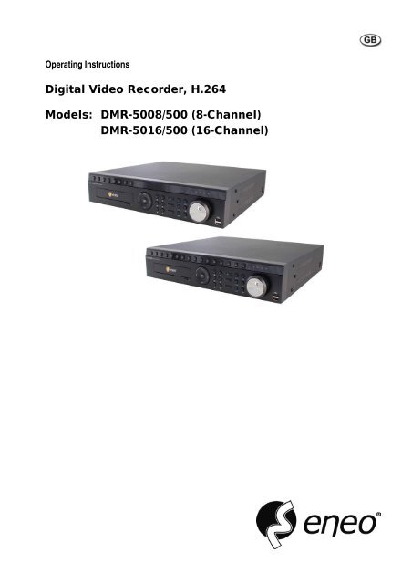
Operating Instructions<strong>Digital</strong> <strong>Video</strong> <strong>Recorder</strong>, <strong>H.264</strong><strong>Models</strong>: <strong>DMR</strong>-<strong><strong>500</strong>8</strong>/<strong>500</strong> (8-<strong>Channel</strong>)<strong>DMR</strong>-5016/<strong>500</strong> (16-<strong>Channel</strong>)
<strong>Digital</strong> <strong>Video</strong> <strong>Recorder</strong>WARNINGRISK OF ELECTRIC SHOCKDO NOT OPENWARNING: TO REDUCE THE RISK OF ELECTRIC SHOCK,DO NOT REMOVE COVER (OR BACK).NO USER-SERVICEABLE PARTS INSIDE.REFER SERVICING TO QUALIFIEDSERVICE PERSONNEL.The lightning flash with arrowhead symbol, within an equilateral triangle, is intended to alertthe user to the presence of uninsulated "dangerous voltage" within the product’s enclosurethat may be of sufficient magnitude to constitute a risk of electric shock.The exclamation point within an equilateral triangle is intended to alert the user to the presenceof important operating and maintenance (servicing) instructions in the literature accompanyingthe appliance.COMPLIANCE NOTICE OF FCC:THIS EQUIPMENT HAS BEEN TESTED AND FOUND TO COMPLY WITH THE LIMITS FOR A CLASS A DIGITALDEVICE, PURSUANT TO PART 15 OF THE FCC RULES. THESE LIMITS ARE DESIGNED TO PROVIDEREASONABLE PROTECTION AGAINST HARMFUL INTERFERENCE WHEN THE EQUIPMENT IS OPERATED INA COMMERCIAL ENVIRONMENT. THIS EQUIPMENT GENERATES, USES, AND CAN RADIATE RADIOFREQUENCY ENERGY AND IF NOT INSTALLED AND USED IN ACCORDANCE WITH THE INSTRUCTIONMANUAL, MAY CAUSE HARMFUL INTERFERENCE TO RADIO COMMUNICATIONS. OPERATION OF THISEQUIPMENT IN A RESIDENTIAL AREA IS LIKELY TO CAUSE HARMFUL INTERFERENCE, IN WHICH CASEUSERS WILL BE REQUIRED TO CORRECT THE INTERFERENCE AT THEIR OWN EXPENSE.WARNING: CHANGES OR MODIFICATIONS NOT EXPRESSLY APPROVED BY THE PARTY RESPONSIBLE FORCOMPLIANCE COULD VOID THE USER’S AUTHORITY TO OPERATE THE EQUIPMENT.THIS CLASS OF DIGITAL APPARATUS MEETS ALL REQUIREMENTS OF THE CANADIAN INTERFERENCE-CAUSING EQUIPMENT REGULATIONS.The information in this manual is believed to be accurate as of the date of publication. We are not responsible for anyproblems resulting from the use thereof. The information contained herein is subject to change without notice. Revisionsor new editions to this publication may be issued to incorporate such changes.The software included in this product contains some Open Sources. You may obtain the complete corresponding sourcecode from us. See the Open Source Guide on the software CD (OpenSourceGuide\OpenSourceGuide.pdf) or as a printeddocument included along with the User's Manual.i
User’s ManualImportant Safeguards1. Read InstructionsAll the safety and operating instructions should be read before theappliance is operated.2. Retain InstructionsThe safety and operating instructions should be retained for futurereference.3. CleaningUnplug this equipment from the wall outlet before cleaning it. Do notuse liquid aerosol cleaners. Use a damp soft cloth for cleaning.4. AttachmentsNever add any attachments and/or equipment without the approval ofthe manufacturer as such additions may result in the risk of fire, electricshock or other personal injury.5. Water and/or MoistureDo not use this equipment near water or in contact with water.6. VentilationPlace this equipment only in an upright position. This equipment has anopen-frame Switching Mode Power Supply (SMPS), which can cause afire or electric shock if anything is inserted through the ventilation holeson the side of the equipment.7. AccessoriesDo not place this equipment on an unstable cart, stand or table. Theequipment may fall, causing serious injury to a child or adult, andserious damage to the equipment. Wall or shelf mounting should followthe manufacturer's instructions, and should use a mounting kit approvedby the manufacturer.This equipment and cart combination should be moved with care. Quickstops, excessive force, and uneven surfaces may cause the equipmentand cart combination to overturn.8. Power SourcesThis equipment should be operated only from the type of power sourceindicated on the marking label. If you are not sure of the type of power,please consult your equipment dealer or local power company.9. Power CordsOperator or installer must remove power and TNT connections beforehandling the equipment.10. LightningFor added protection for this equipment during a lightning storm, or whenit is left unattended and unused for long periods of time, unplug it from thewall outlet and disconnect the antenna or cable system. This will preventdamage to the equipment due to lightning and power-line surges.11. OverloadingDo not overload wall outlets and extension cords as this can result in therisk of fire or electric shock.12. Objects and LiquidsNever push objects of any kind through openings of this equipment as theymay touch dangerous voltage points or short out parts that could result in afire or electric shock. Never spill liquid of any kind on the equipment.13. ServicingDo not attempt to service this equipment yourself. Refer all servicing toqualified service personnel.14. Damage requiring ServiceUnplug this equipment from the wall outlet and refer servicing toqualified service personnel under the following conditions:A. When the power-supply cord or the plug has been damaged.B. If liquid is spilled, or objects have fallen into the equipment.C. If the equipment has been exposed to rain or water.D. If the equipment does not operate normally by following the operatinginstructions, adjust only those controls that are covered by the operatinginstructions as an improper adjustment of other controls may result indamage and will often require extensive work by a qualified technicianto restore the equipment to its normal operation.E. If the equipment has been dropped, or the cabinet damaged.F. When the equipment exhibits a distinct change in performance ─ thisindicates a need for service.15. Replacement PartsWhen replacement parts are required, be sure the service technician hasused replacement parts specified by the manufacturer or that have the samecharacteristics as the original part. Unauthorized substitutions may resultin fire, electric shock or other hazards.16. Safety CheckUpon completion of any service or repairs to this equipment, ask the servicetechnician to perform safety checks to determine that the equipment is inproper operating condition.17. Field InstallationThis installation should be made by a qualified service person andshould conform to all local codes.18. Correct BatteriesWarning: Risk of explosion if battery is replaced by an incorrect type.Dispose of used batteries according to the instructions.19. TmraA manufacturer’s maximum recommended ambient temperature (Tmra)for the equipment must be specified so that the customer and installer maydetermine a suitable maximum operating environment for the equipment.20. Elevated Operating Ambient TemperatureIf installed in a closed or multi-unit rack assembly, the operating ambienttemperature of the rack environment may be greater than room ambient.Therefore, consideration should be given to installing the equipment in anenvironment compatible with the manufacturer’s maximum rated ambienttemperature (Tmra).21. Reduced Air FlowInstallation of the equipment in the rack should be such that the amountof airflow required for safe operation of the equipment is not compromised.22. Mechanical LoadingMounting of the equipment in the rack should be such that a hazardouscondition is not caused by uneven mechanical loading.23. Circuit OverloadingConsideration should be given to connection of the equipment to supplycircuit and the effect that overloading of circuits might have on over currentprotection and supply wiring. Appropriate consideration of equipmentnameplate ratings should be used when addressing this concern.24. Reliable Earthing (Grounding)Reliable grounding of rack mounted equipment should be maintained.Particular attention should be given to supply connections other than directconnections to the branch circuit (e.g., use of power strips).WEEE (Waste Electrical & Electronic Equipment)Correct Disposal of This Product(Applicable in the European Union and other European countries with separate collection systems)This marking shown on the product or its literature, indicates that it should not be disposed with other household wastes at theend of its working life. To prevent possible harm to the environment or human health from uncontrolled waste disposal, pleaseseparate this from other types of wastes and recycle it responsibly to promote the sustainable reuse of material resources.Household users should contact either the retailer where they purchased this product, or their local government office, fordetails of where and how they can take this item for environmentally safe recycling.Business users should contact their supplier and check the terms and conditions of the purchase contract. This product shouldnot be mixed with other commercial wastes for disposal.ii
<strong>Digital</strong> <strong>Video</strong> <strong>Recorder</strong>Table of ContentsChapter 1 — Introduction .........................................................................................................1Feature ................................................................................................................................1Technical Overview..............................................................................................................1Chapter 2 — Installation...........................................................................................................3Package Contents................................................................................................................3Required Installation Tools...................................................................................................3<strong>Video</strong> Input ......................................................................................................................3<strong>Video</strong> Loop Through ........................................................................................................4Factory Reset Switch.......................................................................................................4HD/SD Out Selector.........................................................................................................4Network Port....................................................................................................................4iSCSI Port........................................................................................................................4eSATA Port......................................................................................................................5RS232C Port....................................................................................................................5RS485 Port ......................................................................................................................5Alarm Input/Output...........................................................................................................5Audio In/Out.....................................................................................................................6<strong>Video</strong> Out.........................................................................................................................6Power Cord Connector ....................................................................................................7Chapter 3 — Configuration.......................................................................................................8Front Panel Controls ............................................................................................................8Camera Buttons (1 to 16).................................................................................................9Enter Button.....................................................................................................................9Arrow Buttons ..................................................................................................................9Menu Button ....................................................................................................................9ZOOM Button.................................................................................................................10PTZ Button ....................................................................................................................10Panic Button ..................................................................................................................10LED................................................................................................................................10Display Button................................................................................................................10Monitor Button ...............................................................................................................10Bookmark Button ...........................................................................................................10Freeze Button ................................................................................................................10Alarm Button..................................................................................................................10Playback Buttons ...........................................................................................................10Jog Dial, Shuttle Ring ....................................................................................................11USB Port........................................................................................................................11ID Button on Remote Control.........................................................................................11Sequence Button on Remote Control ............................................................................11Clip Copy Button on Remote Control .............................................................................11Turning on the Power.........................................................................................................12Initial Unit Setup.................................................................................................................12Setup Screen .....................................................................................................................13System Setup.....................................................................................................................14General..........................................................................................................................14Date/Time ......................................................................................................................16iii
User’s ManualAccount..........................................................................................................................17Storage..........................................................................................................................19Monitoring......................................................................................................................20Recording Setup ................................................................................................................21General..........................................................................................................................21Schedule........................................................................................................................23Pre-Event.......................................................................................................................25Archive...........................................................................................................................25Network Setup ...................................................................................................................26General..........................................................................................................................26IP Address .....................................................................................................................27DVRNS ..........................................................................................................................29RTSP.............................................................................................................................30Notification.....................................................................................................................31iSCSI .............................................................................................................................32Event Setup .......................................................................................................................34Motion............................................................................................................................34Alarm-In .........................................................................................................................35<strong>Video</strong> Loss.....................................................................................................................36<strong>Video</strong> Blind ....................................................................................................................36Text-In ...........................................................................................................................37Device Setup......................................................................................................................39Audio .............................................................................................................................39Alarm-Out ......................................................................................................................39Remote Control..............................................................................................................40Display Setup.....................................................................................................................41OSD...............................................................................................................................41Primary Monitor .............................................................................................................42Secondary Monitor.........................................................................................................43Spot Monitor ..................................................................................................................44Status Setup ......................................................................................................................45Event .............................................................................................................................45Storage..........................................................................................................................46Camera Setup....................................................................................................................47General..........................................................................................................................47PTZ................................................................................................................................47Chapter 4 — Operation ..........................................................................................................49Turning on the Power.........................................................................................................49Live Monitoring...................................................................................................................49Live Monitoring Menu.....................................................................................................50Active Cameo Mode ......................................................................................................51Zoom Mode ...................................................................................................................52PTZ Mode......................................................................................................................52Event Monitoring............................................................................................................53Covert Camera ..............................................................................................................53Spot Monitoring..............................................................................................................54Recording <strong>Video</strong> ................................................................................................................54Panic Recording ............................................................................................................54Recording Audio ................................................................................................................54Playing Recorded <strong>Video</strong>.....................................................................................................54iv
<strong>Digital</strong> <strong>Video</strong> <strong>Recorder</strong>Searching <strong>Video</strong>.................................................................................................................56Search Menu .................................................................................................................56Event Log Search ..........................................................................................................58Record Table Search.....................................................................................................59Motion Search................................................................................................................61Text-In Search ...............................................................................................................62Bookmarks.....................................................................................................................64Clip-Copy.......................................................................................................................64Print ...............................................................................................................................66Disk Mirroring.....................................................................................................................67Appendix ................................................................................................................................68USB Hard Disk Drive Preparation ......................................................................................68Preparing the USB hard disk drive in Windows 2000.....................................................68Preparing the USB hard disk drive in Windows 98.........................................................68Text-In Search Examples...................................................................................................69Search Example I ..........................................................................................................69Search Example II .........................................................................................................69WebGuard..........................................................................................................................70Web Monitoring Mode....................................................................................................71Web Search Mode .........................................................................................................73Time Overlap .....................................................................................................................74System Log Notices ...........................................................................................................75Error Code Notices.............................................................................................................75Connector Pin Outs............................................................................................................76I/O Connector Pin Outs..................................................................................................76RS485 Connector Pin Outs............................................................................................76Map of Screens..................................................................................................................77Troubleshooting .................................................................................................................78Specifications.....................................................................................................................78List of IllustrationsFigure 1 : Typical DVR installation. ...........................................................................................................2Figure 2 : 16-<strong>Channel</strong> DVR rear panel......................................................................................................3Figure 3 : 16-<strong>Channel</strong> DVR front panel.....................................................................................................8Figure 4 : Infrared remote control..............................................................................................................9Figure 5 : Login screen. ..........................................................................................................................12Figure 6 : Logout screen. ........................................................................................................................12Figure 7 : Setup screen...........................................................................................................................13Figure 8 : System – General setup screen..............................................................................................14Figure 9 : System – Date/Time setup screen. .........................................................................................16Figure 10 : System – Account setup screen............................................................................................17Figure 11 : System – Storage setup screen. ...........................................................................................19Figure 12 : System – Monitoring setup screen........................................................................................20Figure 13 : Record – General setup screen. ...........................................................................................21Figure 14 : Record – Schedule setup screen. .........................................................................................23Figure 15 : Schedule – Settings (Advanced Mode) setup screen. ..........................................................24v
User’s ManualFigure 16 : Record – Pre-Event setup screen. ........................................................................................25Figure 17 : Record – Archive setup screen. ............................................................................................25Figure 18 : Network – General setup screen...........................................................................................26Figure 19 : Network – IP Address (Manual) setup screen.......................................................................27Figure 20 : Network – DVRNS setup screen...........................................................................................29Figure 21 : Network – RTSP setup screen..............................................................................................30Figure 22 : Network – Notification setup screen......................................................................................31Figure 23 : Network – iSCSI setup screen. .............................................................................................32Figure 24 : Event – Motion setup screen.................................................................................................34Figure 25 : Event – Alarm-In setup screen..............................................................................................35Figure 26 : Event – <strong>Video</strong> Loss setup screen..........................................................................................36Figure 27 : Event – <strong>Video</strong> Blind setup screen. ........................................................................................36Figure 28 : Event – Text-In setup screen. ...............................................................................................37Figure 29 : Text-In Device screen. ..........................................................................................................38Figure 30 : Device – Audio setup screen. ...............................................................................................39Figure 31 : Device – Alarm-Out setup screen. ........................................................................................39Figure 32 : Device – Remote Control setup screen. ...............................................................................40Figure 33 : Display – OSD setup screen.................................................................................................41Figure 34 : Display – Primary Monitor setup screen. ..............................................................................42Figure 35 : Display – Secondary Monitor setup screen...........................................................................43Figure 36 : Display – Spot Monitor setup screen. ...................................................................................44Figure 37 : Status – Event setup screen. ................................................................................................45Figure 38 : Status – Storage setup screen..............................................................................................46Figure 39 : Camera – General setup screen. ..........................................................................................47Figure 40 : Camera – PTZ setup screen.................................................................................................47Figure 41 : Live Monitoring menu............................................................................................................49Figure 42 : PTZ Select Camera menu. ...................................................................................................52Figure 43 : PTZ Preset menu..................................................................................................................52Figure 44 : Select Playback Camera menu.............................................................................................55Figure 45 : Search menu.........................................................................................................................56Figure 46 : Event Log Search screen......................................................................................................58Figure 47 : Record Table Search screen. ...............................................................................................60Figure 48 : Motion Search screen. ..........................................................................................................61Figure 49 : Text-In Search screen...........................................................................................................62Figure 50 : Bookmarks screen. ...............................................................................................................64Figure 51 : Clip-Copy screen. .................................................................................................................64Figure 52 : Print screen...........................................................................................................................66Figure 53 : System – Storage setup screen. ...........................................................................................67vi
<strong>Digital</strong> <strong>Video</strong> <strong>Recorder</strong>Chapter 1 — IntroductionFeatureYour color digital video recorder (DVR) provides recording capabilities for eight or 16 camera inputs. It providesexceptional picture quality in both live and playback modes, and offers the following features:• 8 or 16 Composite <strong>Video</strong> Input Connectors• Compatible with Color (NTSC or PAL) and B&W (CCIR and EIA-170) <strong>Video</strong> Sources• Auto Detection for NTSC and PAL• <strong>H.264</strong> Codec• Multiple Monitor Connectors: 1 HDMI, 2 VGA, 2 BNC <strong>Video</strong> Out, 1 Spot• Multiple Search Engines (Date/Time, Record Table, Event)• Real-time Recording (480/400 Images per Second (NTSC/PAL) with Very High (D1) Resolution)• “Loop-Through” <strong>Video</strong> Connectors• Continuous Recording in Disk Overwrite Mode• Pentaplex Functionality (Monitoring, Recording, Playback, Archiving and Transmission at the same time)• <strong>Video</strong> Archiving via eSATA Interface• 2 USB 2.0 Ports• Continues Recording while Archiving, Transmitting to Remote Site and during Playback• User-friendly Graphical User Interface (GUI) Menu System• Multiple Recording Modes (Time-lapse, Pre-event, Event and Panic)• Two-way Audio Communication• 16-<strong>Channel</strong> Audio Recording and 1-<strong>Channel</strong> Audio Playback• Text Input for ATM and POS• Alarm Connections Include: Input, Output and Reset Input• Built-in Alarm Buzzer• Live or Recorded <strong>Video</strong> Access via Ethernet• Time Synchronization using industry standard protocol• Built-in DVD RW Drive• IR Remote Control• Self-diagnostics with automatic notification including hard disk drive S.M.A.R.T. protocolTechnical OverviewIn addition to replacing both a time-lapse VCR and a multiplexer in a security installation, your DVR has many featuresthat make it much more powerful and easier to use than even the most advanced VCR.The DVR converts analog NTSC or PAL video to digital images and records them on a hard disk drive. Using a harddisk drive allows you to access recorded video almost instantaneously; there is no need to rewind tape. The technologyalso allows you to view recorded video while the DVR continues recording video.<strong>Digital</strong>ly recorded video has several advantages over analog video recorded on tape. There is no need to adjust tracking.You can freeze frames, fast forward, fast reverse, slow forward and slow reverse without image streaking or tearing.<strong>Digital</strong> video can be indexed by time or events, and you can instantly view video after selecting the time or event.Your DVR can be set up for event or time-lapse recording. You can define times to record, and the schedule can changefor different days of the week and user defined holidays.The DVR can be set up to alert you when the hard disk drive is full, or it can be set to record over the oldest video oncethe disk is full.Your DVR supports disk mirroring functions to prevent any unexpected loss of recorded video data that might be causedby disk damage or corruption.1
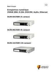
User’s ManualYour DVR uses a proprietary encryption scheme making it nearly impossible to alter video.You can view video and control your DVR remotely by connecting via Ethernet. There are eSATA and iSCSI portsthat can be used to record or archive (eSATA interface only) video to external hard disk drives, and there are two USBports that can be used to upgrade the system or copy video clips to external hard disk and flash drives.Figure 1 : Typical DVR installation.NOTE: This manual covers the 8- and 16-channel digital video recorders. The DVRs are identical except for thenumber of cameras and alarms that can be connected and the number of cameras that can be displayed.For simplicity, the illustrations and descriptions in this manual refer to the 16-camera model.2
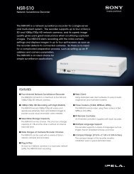
<strong>Digital</strong> <strong>Video</strong> <strong>Recorder</strong>Chapter 2 — InstallationPackage ContentsThe package contains the following:• <strong>Digital</strong> <strong>Video</strong> <strong>Recorder</strong>• Power Cord• User’s Manual (This Document)• RAS Software CD and User’s Manual• Rack-mount Kit• Assembly Screws for Adding Hard Disk Drives• SATA Cables• Audio Extension Cable• Infrared Remote ControlRequired Installation ToolsNo special tools are required to install the DVR. Refer to the installation manuals for the other items that make up partof your system.Figure 2 : 16-<strong>Channel</strong> DVR rear panel.<strong>Video</strong> Input <strong>Video</strong> Loop Through Factory Reset SwitchHD/SD Out Selector Network Port iSCSI PorteSATA Port RS232C Port RS485 PortAlarm Input/Output Audio In/Out <strong>Video</strong> OutPower Cord ConnectorYour DVR can be used with either NTSC or PAL equipment.NOTE: You cannot mix NTSC and PAL equipment. For example you cannot use a PAL camera and an NTSCmonitor.<strong>Video</strong> InputConnect the coaxial cables from the video sources to the BNC <strong>Video</strong> In connectors.3
<strong>Digital</strong> <strong>Video</strong> <strong>Recorder</strong>CAUTION: If the iSCSI device is shut down while the device is operating, the DVR system might notoperate normally.eSATA PortAn eSATA port is provided to connect external storage devices for recording or archiving video. Connectthe external eSATA hard disk drive (RAID) cable to the eSATA port.CAUTION: Do NOT connect or disconnect eSATA devices while the DVR power is on. The DVR mustbe powered down to connect or disconnect eSATA devices. Power up eSATA devicesso they are ready for operation before powering up the DVR. Power down eSATA devicesafter powering down the DVR and then disconnect eSATA devices.CAUTION: If the eSATA device is shut down while the device is operating, the DVR system mightnot operate normally.RS232C PortAn RS232 port is provided to connect a remote control keyboard.RS485 PortThe DVR can be controlled remotely by an external device or control system, such as a control keyboard,using RS485 half-duplex serial communications signals. The RS485 connector can also be used to controlPTZ (pan, tilt, zoom) cameras. Connect RX+/TX+ and RX-/TX- of the control system to the + and –(respectively) of the DVR. See Chapter 3 ─ Configuration and the PTZ camera or remote controllermanufacture’s manual for configuring the RS485 connection.Alarm Input/OutputNOTE: To make connections on the Alarm Connector Strip, press and hold the button and insert the wire in thehole below the button. After releasing the button, tug gently on the wire to make certain it is connected.To disconnect a wire, press and hold the button above the wire and pull out the wire.AI 1 to 16 (Alarm-In): You can use external devices to signal the DVR to react to events. Mechanical or electricalswitches can be wired to the AI (Alarm-In) and GND (Ground) connectors. The threshold voltage of electrical switchesfor NC (Normally Closed) is above 2.4V and for NO (Normally Open) is below 0.3V, and should be stable at least 0.5seconds to be detected. The voltage range of alarm input is from 0V to 5V. See Chapter 3 ─ Configuration for configuringalarm input.GND (Ground): Connect the ground side of the Alarm input and/or alarm output to the GND connector.NOTE: All the connectors marked GND are common.NC/NO (Relay Alarm Outputs): The DVR can activate external devices such as buzzers or lights. Connect the deviceto the C (Common) and NC (Normally Closed) or C and NO (Normally Open) connectors. NC/NO is a relay outputwhich sinks 2A@125VAC and 1A@30VDC. See Chapter 3 ─ Configuration for configuring alarm output.ARI (Alarm Reset In): An external signal to the Alarm Reset In can be used to reset both the Alarm Out signal andthe DVR’s internal buzzer. Mechanical or electrical switches can be wired to the ARI (Alarm Reset In) and GND (Ground)connectors. The threshold voltage is below 0.3V and should be stable at least 0.5 seconds to be detected. Connect thewires to the ARI and GND connectors.5
User’s ManualAudio In/OutNOTE: It is the user’s responsibility to determine if local laws and regulations permit recording audio.<strong>Video</strong> OutYour DVR can record audio from up to 16 sources. Connect the audiosources to Audio In 1 to Audio In 16 as needed using RCA jacks. ConnectAudio Out to your amplifier. Use the provided audio extension cable toconnect the audio sources to Audio In 5 to 16.The DVR does not have amplified audio output, so you will need a speaker with an amplifier. The DVRdoes not have a pre-amplifier for audio input, so the audio input should be from an amplified source, notdirectly from a microphone.A HDMI (High-Definition Multimedia Interface) connector is provided so that you can use a HDMImonitor as your primary monitor. Use the cable supplied with your monitor to connect it to the DVR.A VGA connector is provided so that you can use a standard, multi-sync computer monitor as yourprimary or secondary monitor. Use the cable supplied with your monitor to connect it to the DVR.Connect the primary or secondary monitor to the <strong>Video</strong> Out connector.Connect the spot monitor to the SPOT connector as needed.NOTE: When using HDMI monitors, change the monitor display mode to HD mode by setting the HD/SD Outselector on the rear panel to the HD OUT position. HDMI video out will only enable in the HD display mode.VGA video out on the primary monitor will disable in the SD display mode.Composite (BNC) video out on the primary monitor will disable in the HD display mode.Monitor Connection Examples:< HD Display Mode > < SD Display Mode >NOTE: Connect the monitor before the DVR boots so that video can be displayed on the monitor with the resolutionyou have set during system setup.6
<strong>Digital</strong> <strong>Video</strong> <strong>Recorder</strong>Power Cord ConnectorConnect the AC power cord to the DVR and then to a wall outlet.WARNING: ROUTE POWER CORDS SO THAT THEY ARE NOT A TRIPPING HAZARD. MAKECERTAIN THE POWER CORD WILL NOT BE PINCHED OR ABRADED BY FURNITURE.DO NOT INSTALL POWER CORDS UNDER RUGS OR CARPET.THE POWER CORD HAS A GROUNDING PIN. IF YOUR POWER OUTLET DOES NOTHAVE A GROUNDING PIN RECEPTACLE, DO NOT MODIFY THE PLUG. DO NOTOVERLOAD THE CIRCUIT BY PLUGGING TOO MANY DEVICES IN TO ONE CIRCUIT.Your DVR is now ready to operate. Refer to Chapter 3 ─ Configuration and Chapter 4 ─ Operation.7
User’s ManualChapter 3 — ConfigurationNOTE: Your DVR should be completely installed before proceeding. Refer to Chapter 2 — Installation.Front Panel ControlsFigure 3 : 16-<strong>Channel</strong> DVR front panel.Camera Buttons Enter Button Arrow Buttons Menu ButtonZoom Button PTZ Button Panic Button LEDDisplay Button Monitor Button Bookmark Button Freeze ButtonAlarm Button Playback Buttons Jog Dial, Shuttle Ring USB PortThe front panel looks and operates much like a VCR combined with a multiplexer. Many of the buttons have multiplefunctions. The buttons on the infrared remote control, while laid out differently, perform the same functions as thoseon the front panel. The following describes each button and control. Take a few minutes to review the descriptions.You will use these to initially set up your DVR and for daily operations.NOTE: The infrared sensor on the DVR is just to the left of LEDs. Make certain that nothing blocks the sensor,or the remote control will not function properly.You can also use a USB mouse (not supplied) to navigate through the screens and menus much like youwould on a computer.8
<strong>Digital</strong> <strong>Video</strong> <strong>Recorder</strong>Figure 4 : Infrared remote control.NOTE: For simplicity, the button descriptions in this manual refer to the front panel buttons.Camera Buttons (1 to 16)Pressing the individual camera buttons will cause the selected camera to display full screen. Buttons 1 to 9 are alsoused to enter passwords.Enter ButtonThe(Enter) button selects a highlighted item or completes an entry that you have made during system setup.Arrow ButtonsThese buttons are used to navigate through menus and GUI. You can also use them to change numbers by highlightinga number in the menu and using the Up and Down arrow buttons to increase or decrease the number’s value.These buttons are also used to control Pan and Tilt when in the PTZ mode.Menu ButtonPressing the MENU button enters the Setup screen. You will need to enter the authorized user and password to accessSetup. Pressing the button also closes the current menu or setup dialog box. In the Playback mode, pressing the buttondisplays the Search menu. In the Search mode clip-copying can be done instantly by pressing and holding the buttonfor three or more seconds.9
User’s ManualZOOM ButtonPressing the ZOOM button zooms the current image on the screen. A PIP with a rectangle temporarily displays showingwhat area of the screen has been enlarged. You can use the arrow buttons to move the rectangle to another area.NOTE: Entering the zoom mode will NOT be supported while in the SD display mode.PTZ ButtonPressing the PTZ button enters the PTZ (Pan/Tilt/Zoom) mode which allows you to control properly configured cameras.Panic ButtonPressing the PANIC button starts panic recoding of all camera channels, and displays on the screen. Pressing the buttonagain will stop panic recording.LED• Power LED: The Power LED is lit when the unit is On.• Network LED: The Network LED is lit when the unit is connected to a network via Ethernet.• iSCSI LED: The iSCSI LED is lit when the iSCSI device is connected to the DVR.• HDD LED: The HDD LED flickers when the DVR is recording or searching video on the hard disk drive.Display ButtonPressing the DISPLAY button toggles between different display formats. The available formats are: 2x2, 3x2, 3x3, 4x3or 4x4 (2x2 or 4x4 on a Spot Monitor).Monitor ButtonPressing the MONITOR button toggles the monitor selection between Primary (MONITOR 1 on the remote control),Secondary (MONITOR 2) and Spot (MONITOR 3). You can select the screen format and sequence monitoring of theselected monitor.Bookmark ButtonWhen in the playback mode, pressing the BOOKMARK button adds the current playback point to the bookmark list ormoves to the registered bookmark point.Freeze ButtonPressing the FREEZE button freezes the current live screen.Alarm ButtonThe ALARM button has two functions. First, it will reset the DVR’s outputs including the internal buzzer during analarm. Second, it will display the event log when you are in the live monitoring mode unless there is an active alarm.Playback Buttons• Backward: When in the pause mode, pressing theto Zoom Out while in the PTZ mode.button moves to the next image. The button is also used10
<strong>Digital</strong> <strong>Video</strong> <strong>Recorder</strong>• Forward: When in the pause mode, pressing the button moves to the previous image. The button is also usedto Zoom In while in the PTZ mode.• Rewind: Pressing the button plays video backward at high speed. Pressing the button again toggles the playbackspeed from , and . The button is also used for Near Focus in the PTZ mode.• Play/Pause: Pressing the button plays back video at regular speed. The screen displays when the DVR isin the Pause mode and the screen displays when the DVR is playing back video. The button is also used for FarFocus in the PTZ mode.• Fast Forward: Pressing the button plays video forward at high speed. Pressing the button again toggles theplayback speed from , and . The button is also used to load a Preset View in the PTZ mode.• Search/Stop: Pressing the button while in the Live Monitoring mode enters the Search mode. Pressing thebutton while in the Search mode returns the DVR to the Live Monitoring mode. The button is also used to savePresets while in the PTZ mode.Jog Dial, Shuttle Ring• Jog Dial: When in the playback mode, you can play video forward image-by-image by turning the Jog Dial clockwiseand backward image-by-image by turning the Jog Dial counterclockwise. When in the Setup mode, you can changenumber values by highlighting the item in the menu and turning Jog Dial clockwise or counterclockwise to increaseor decrease the number.• Shuttle Ring: The Shuttle Ring only functions in the Playback mode. The Shuttle Ring is spring loaded and returnsto the center position when released. Turning the ring clockwise plays video forward. Turning the ring counterclockwiseplays video backward. Playback speed varies with the amount the ring is turned. The playback speeds are , ,, x0.5, , , and . When you release the ring, it snaps back to the center position and the videopauses.USB PortTwo USB ports on the front panel are provided to connect external hard disk or flash drives for video clip copying orsystem upgrades. Position external drives close enough to the DVR so that you can make the cable connections, usuallyless than 6 feet. Use the USB cable provided with the hard disk drive to connect it to the DVR.A USB mouse (not supplied) can be connected to one of the ports. You can use the mouse to navigate through thescreens and menus much like you would on a computer.A PostScript USB printer (not supplied) can be connected to one of the ports. You can print selected images resultingfrom a search. Refer to Chapter 4 — Operation, Searching <strong>Video</strong>.A USB to Serial converter can be connected to the USB port. Multiple text-in devices can be used with a USB to Serialconverter.ID Button on Remote ControlIf a DVR System ID is set to 0, the infrared remote control will control that DVR without any additional operations.(Refer to the System General setup screen in this chapter for further information on setting the System ID.) If the systemID is 1 to 16, you must to press the ID button on the remote control and then press the number button (1 to 16) in orderto control that DVR. If the System ID of two or more DVRs is set to 0, those DVRs will react to the infrared remotecontrol at the same time.Sequence Button on Remote ControlPressing SEQUENCE button displays live channels sequentially.Clip Copy Button on Remote ControlPressing the CLIP COPY button allows you to copy video clips.11
User’s ManualTurning on the PowerConnecting the power cord to the DVR turns on the unit. The unit takes approximately 60 seconds to initialize.Initial Unit SetupBefore using your DVR for the first time, you will want to establish the initial settings. This includes items such astime and date, display language, camera, remote control, record mode, network and password. Your DVR can be setup using various screens and dialog boxes.Throughout the screens you will see . Highlighting the and pressing the button gives you the opportunity toreset that screen to its default settings. After you are finished with any setup screen, you can highlight Save and pressthe button to save the changes and exit the screen. If you do not wish to save the changes, highlight Cancel andpress the button to exit the screen.Press the MENU button or move the mouse pointer to the top of the screen and then selectMonitoring menu to enter the setup screens. The Login screen appears.(Login) in the LiveSelect a User and enter the password by pressing the appropriatecombination of Camera number buttons and then the button. Thereis no default password when logging in the admin user for the firsttime.Figure 5 : Login screen.NOTE: To assure the secure management of the system, setting up a password is strongly recommended.If you cannot use the front panel buttons, click the button using the mouse to enter a password, andthe virtual keyboard displays. See instructions below for using the virtual keyboard.To log the user out of the system, press the MENU button or move the mouse pointer to the top of thescreen and then select (Logout) in the Live Monitoring menu. The Logout screen displays asking youto confirm whether or not you want to log out the current user.Figure 6 : Logout screen.12
<strong>Digital</strong> <strong>Video</strong> <strong>Recorder</strong>Setup ScreenSystemRecordNetworkEventDeviceDisplayStatusCameraFigure 7 : Setup screen.Press the MENU button or move the mouse pointer to the top of the screen and then selectMonitoring menu to enter the setup screen.(Setup) in the LiveWhile setting up the DVR, there will be many opportunities to enter names and titles. When making these entries, aVirtual Keyboard will appear.Use the arrow keys to highlight the character you want in the name or title and pressthe button. That character appears in the title bar and the cursor moves to the nextposition. Pressing toggles between the upper and lower case keyboards,backspaces, and deletes entered characters.Special characters can be created using ^ and a capital letter; e.g., ^J for NL (New Line),^M for CR (Carriage Return). Special characters are commonly used by text input devicesand will be useful when performing Text-In Searches.13
User’s ManualSystem SetupGeneralHighlight General and press thebutton, and the General screen appears.Figure 8 : System – General setup screen.In the General screen, you can name the site location, assign a System ID number, select the language the screens aredisplayed in, display software version number, upgrade the software, show the System Log, display recorded time data,and clear all data.Highlight the Site box and press the button. A virtual keyboard appears that you can use to enter a Site Name. Onceyou have entered your title, highlight OK and press the button.Highlight the box beside System ID and press the button. Change the number by highlighting it and using the Upand Down arrow buttons to increase and decrease the number from 0 to 99.NOTE: The System ID number is used to identify the unit when it is connected with other DVRs through theRS485 port. You cannot use the same ID number for two or more DVRs that are in the same RS485network. It is possible to have multiple DVRs with System ID 0 that are in the same area as long as theyare not part of an RS485 network. If this is the case, all will be controlled at the same time when usingthe infrared remote control.Highlight the box beside Language and pressthe desired language and press the button.The box beside Version displays the software version of the DVR.button. A drop-down menu displays the available languages. HighlightTo upgrade the software, connect a USB device containing the upgrade package file to the DVR. Highlight Upgrade…and press the button. The Upgrade screen appears. The screen displays the upgrade package file names that areavailable. The “.rui” indicates that the file is for software upgrades and “.ofi” indicates that the file is for optical drivefirmware upgrades.Select the desired file and press the button. Highlighting the Install button and pressing the button will installthe selected software package. Highlighting the Cancel button and pressing the button will close the window withoutupgrading the software. If the upgrade package file is not installed on the DVR properly, you will get an error message.The system restarts automatically after completing the upgrade.14
<strong>Digital</strong> <strong>Video</strong> <strong>Recorder</strong>CAUTION: The USB device must be FAT16 or FAT32 format.You can import saved DVR settings or export the current DVR settings. To import saved DVR settings, connect theUSB device containing the setup file (.dat) to the DVR. Highlight Setup – Import… and press the button. Selectthe desired setup file and press the Import button to import the selected settings and change the DVR settings accordingly.Highlight Include Network Setup and press the button to toggle between On and Off. When set to Off, the networksettings will not be changed.To export the current DVR settings, connect the USB device to the DVR. Highlight Setup – Export… and press thebutton. Highlight the box beside File name and press the button. A virtual keyboard allows you to enter thefile name. Selecting Export will save the current settings in .dat file format on the USB device.NOTE: Even after changing the DVR settings by importing saved settings, the time-related settings (Date/Time,Time Zone and Daylight Saving Time) will NOT be changed.CAUTION: The USB device must be FAT16 or FAT32 format.Highlight Show System Log… and press thebutton to display the System Log.The System Log screen lists system activities (up to 5,000 from the latest) that have occurred along with the time anddate. The icon will be displayed in the last column for system activities of the remote site. You can scroll throughthe log pages by using the Up and Down arrows, or you can go directly to a log page by entering the log page numberin the box at the bottom left of the screen. Highlight Close and press the button to exit the screen.To export the system log information, connect the USB device to the DVR. Highlight Export… and press the button.Highlight the box beside File name and press the button. A virtual keyboard allows you to enter the file name.Selecting Export will save the log information in .txt file format on the USB device.15
User’s ManualNOTE: When opening the saved .txt file, setting to the proper character encoding and using fixed width fontswill be required to read the file properly.Highlighting Clear All Data and pressing the button will clear all video data. You will be asked to verify that youwish to clear all data before the DVR erases the video data. Clear All Data will not clear the System Log.Highlighting System Shutdown and pressing thewhether or not you want to shut the system down.button. The Shutdown screen displays asking you to confirmAfter selecting Shutdown and pressing thewhen it is safe to disconnect power.button, a screen will appear telling youDate/TimeHighlight Date/Time and press thebutton, and the Date/Time setup screen appears.Figure 9 : System – Date/Time setup screen.Highlight the first box beside Date and press the button. The individual sections of the date will highlight. Usethe Up and Down arrow buttons to change the number. Use the Left and Right arrow buttons to move between month,date and year. Once you have the correct date, press the button.Highlight the Format box beside Date and press thethe button to save your selected format.button. Select from the three available date formats and pressHighlight the first box beside Time and press the button. The individual sections of the time will highlight. Usethe Up and Down arrow buttons to change the number. Use the Left and Right arrow buttons to move between hour,minutes and seconds. Once you have the correct time, press the button.Highlight the Format box beside Time and press thethe button to save your selected format.button. Select from the three available time formats and pressNOTE: The clock will not start running until you have highlighted Save and pressed thebutton.Highlight the box beside Time Zone and press the button. Select your time zone from the list and press the button.Highlight Use Daylight Saving Time and press the button. Pressing the button toggles between On and Off.Highlighting Time Sync.… and pressing the button displays the Time Sync. screen. You can set up timesynchronization between the DVR and standard time servers that are available in most time zones and countries, orbetween the DVR and another DVR.16
<strong>Digital</strong> <strong>Video</strong> <strong>Recorder</strong>Highlight the box beside Automatic Sync. and press thebutton. This toggles between On and Off.Highlight the box beside Time Server and press the button.A virtual keyboard appears that you can use to enter the IPaddress or domain name of the time server.NOTE: You can use the domain name instead of IP addressif you already set up the DNS Server when settingup the LAN.Highlight the box beside Interval and press theto 1 day at various time intervals.button. Set the time interval for synchronization from 30 minutesLast Sync-Time displays the last time the DVR was synchronized with the time server.Highlight Run as Server and press the button. Pressing the button toggles between On and Off. When it isOn, the DVR you are setting up will run as a time server.Highlighting Holiday… and pressing thebutton displays the Holiday screen.You can set up holidays by highlighting + and pressing thedate appears.button. The currentHighlight the month and day and change them by using the Up and Down arrowbuttons. Press the button to add the date. Dates can be deleted by highlightingthe beside the date and pressing the button.NOTE: Holidays that do not fall on the same date each year should be updatedonce the current year’s holiday has passed.AccountHighlight Account and press the button. The Account setup screen displays the authorized groups and users. Youcan add and delete groups and users. When adding a group, you can assign authority levels to the group.Figure 10 : System – Account setup screen.17
User’s ManualThe +/– column is used to collapse and expand user groups. If there is a + or – in this column, it indicates the item isa Group Name. If there is a – in front of the Group Name, it indicates that the group has been “expanded” and all ofthe User Names within that group are displayed below the Group Name. If there is a + in front of the Group Name, itindicates that the group has been “collapsed” and all of the User Names within that group are hidden. To collapse orexpand a group, highlight the +/– column in front of the desired group and press the button.Highlighting a Group Name and pressing thebutton allows you to change the authority levels assigned to the group.CAUTION: Write down the new password and save it in a secure place. If the password is forgotten,the unit must be reset using the Factory Reset Button and all data settings will be lost.Highlighting a User Name and pressing the button allows you to add or change the password assigned to that user.You can also change the group to which the user is assigned.The column can be used to delete a User Name or an entire Group. If the is grayed out, that Group or User cannotbe deleted. Highlight the and press the button. You will be asked to confirm that you want to delete the User orGroup. To delete the User currently logged into the DVR on a local system or a PC running RAS, log the user out ofthe system first and then delete the user.To add a Group, highlight the + Group… box and press the button. A virtual keyboard appears allowing you toenter the Group name. You can use up to 15 characters including spaces in the group name. Enter the name and assignauthority levels to the group.Highlighting the Authority box and pressing the button will togglebetween all authority levels being turned On and Off. Highlightingthe individual authority level boxes and pressing the button willtoggle between that authority level being turned On and Off. Theauthority levels that can be turned On and Off are:• Shutdown – The user can shut the system down on a local system.• Upgrade – The user can upgrade the software on a local system or a PCrunning RAS.• Color Control – The user can control brightness, contrast, hue and saturationfor cameras on a local system or a PC running RAS.• System Check – The user can view the remote system status or checkthe remote system status as a batch process on a PC running RAS.• PTZ Control – The user can control the PTZ camera on a local system or a PC running RAS.• Alarm-Out Control – The user can reset the DVR’s outputs including the internal buzzer during an alarm by pressing the ALARMbutton on a local system or alarm-out control button on a PC running RAS.• Covert Camera View – The user can view video from cameras set as Covert while in the Live Monitoring or Search mode ona local system or a PC running RAS.• Search – The user can access the Search mode on a local system or a PC running RAS.• Clip-Copy – The user can copy video clips on a local system or a PC running RAS.• Setup – The user without Setup authority cannot establish any system settings excluding system shutdown and logout on a localsystem or a PC running RAS.• System Time Change – The user can change the system date and time on a local system or a PC running RAS.• Data Clear – The user can clear all video data or format disks on a local system or a PC running RAS.• PTZ Setup – The user can establish all PTZ settings on a local system or a PC running RAS.• Alarm-Out Setup – The user can establish all Alarm-Out settings on a local system or a PC running RAS.• Covert Camera Setup – The user can establish all Covert Camera settings on a local system or a PC running RAS.• Record Setup – The user can establish all Record settings on a local system or a PC running RAS.To add a User, highlight the + User… box and press the button. Avirtual keyboard appears allowing you to enter the User Name. Enter thename and assign the User to a Group and password. You can use camerabuttons 1 to 9 on the front panel to assign the password. The passwordcan be up to 8 digits. You will be asked to confirm the password.NOTE: In addition to using the front panel buttons or the infrared remote control, you can use the virtual keyboardto assign the password. To display the virtual keyboard click the button using the mouse (not supplied).18
<strong>Digital</strong> <strong>Video</strong> <strong>Recorder</strong>Highlighting the box beside Auto Login allows you to select a User to be automatically logged in when the DVR ispowered up. It can also be set to never automatically login a user.Highlighting the box beside Auto Logout allows you to select from a list of times that the user will be automaticallylogged out. The options are: Never, 1 min., 3 min., 5 min., 10 min., 15 min., 20 min., 30 min. and 1 hr.StorageHighlight Storage and press thestorage devices.button. The Storage setup screen appears and displays information about the DVR’sFigure 11 : System – Storage setup screen.The information in the Type column describes the storage device.The capacity of the storage device is displayed in the Capacity column.The Format column displays whether the device is used for recording (Record), archiving (Archive) or not (Not Using).Not formatted indicates the device is not formatted. indicates when the device has temporary space set aside sothat video clips can be saved on a DVD RW.Highlight the box in the Format column for the desired storage device andpress the button. You will be able to format the device for recording orarchiving. When selecting Not Using from Use As and highlighting theFormat button, the device will not be used for either recording or archiving.You can also set aside space to store temporary files for CD or DVD burningby selecting Partition – CD/DVD Burn.NOTE: The DVR does NOT support USB hard disk drives with a version lower than 2.0.NOTE: iSCSI devices cannot be formatted for archiving.The Information column displays whether the device is being used or not. Other indicates the device has been usedfor another DVR.Highlight the box in the Information column for the desired storage device and press theto check the time information about recorded data.button. You will be able19
User’s ManualIf you want to erase recorded data on the selected device,highlight Clear and press the button. You will be askedwhether or not you want to delete the data.If you want to use a USB hard disk drive, highlight Use andpress the button after connecting the device. HighlightDon’t Use and press the button if you want to stop usingthe device.CAUTION: Do NOT disconnect the USB cable or the power from the device while copying video clips.If the USB cable is disconnected while copying video clips, archived data might be lost.Highlight the boxes beside Mirror and press the button. The DVR can be set up to mirror Source disks to designatedDest. (destination) disks selected from internal hard disk drives. Refer to the Chapter 4 – Disk Mirroring for furtherinformation on setting up disk mirroring.MonitoringHighlight Monitoring and press thebutton, and the Monitoring setup screen appears.Figure 12 : System – Monitoring setup screen.The DVR can be configured to run self-diagnostics and report the results.Highlight the Settings box beside the desired event (System, Check Recording, Check Alarm-In, Disk Almost Full,Disk Bad, or Disk Temperature), and press the button.Highlight the Settings box beside System and press the button. You can select the interval that you want the DVRto run self-diagnostics on the system. You can select from 1 hr. to 30 days or Never.Highlight the Settings box beside Check Recording and press thebutton. The Check Recording screen appears.Highlighting Schedule On and pressing the button toggles On andOff. When set to On, you can select the day, time range and intervalthat you want the DVR to run self-diagnostics on the recorder. TheInterval can be selectable from 1 min. to 7 days or Never. Highlightthe + and press the button to add a schedule item. The box allowsyou to delete a check recording schedule.20
<strong>Digital</strong> <strong>Video</strong> <strong>Recorder</strong>Highlight the Settings box beside Check Alarm-In and press the button. You can select the interval that you wantthe DVR to run self-diagnostics on Alarm Inputs. You can select from 1 hr. to 30 days or Never.Highlight the Settings box beside Disk Almost Full, and press the button. Select the percentage level of disk usageat which you want the DVR to trigger an alert. Percentage levels range from 80% to 99%.Highlight the Settings box beside Disk Bad, and press the button. Select percentage level of bad disk sectors atwhich you want the DVR to trigger an alert. Percentage levels range from 10% to 90%.Highlight the Settings box beside Disk Temperature, and press the button. Select the temperature of hard diskdrive at which you want the DVR to trigger an alert if the temperature exceeds the defined threshold. Refer to the harddisk drive manufacturer’s documentation for the correct temperature setting.The DVR can be set to react to system events. Highlight the Actions box beside the desired event and press thebutton. System events can be associated with an Alarm-Out connector, sound the DVR’s internal buzzer, and/or notifya number of different devices.NOTE: Alarm-Out action cannot be set to System and Panic Record events.Mail notify is the only option available for the System event.For the Notify action to work, the DVR should be registered in the RAS (Remote Administration System).Recording SetupGeneralHighlight General and press thebutton, and the General setup screen appears.Figure 13 : Record – General setup screen.Highlighting Recycle and pressing the button toggles between On and Off. In the Recycle mode, the DVR recordsover the oldest video data once all available storage space has been used. When Recycle is turned off, the DVR stopsrecording once all available storage space has been used.Highlight the Event Record Dwell box and set the length of time you would like to record for the associated event.You can set the dwell from 5 seconds to 15 minutes. Refer to Event Actions screen in this chapter for informationregarding event recording.Highlighting De-Interlace and pressing the button toggles between On and Off. When set to On, the DVR willturn the de-interlace filter on while recording video with Very High (D1) resolution.21
User’s ManualNOTE: The video signal has a time difference of 1/60 second (1/50 second for PAL) between odd and even fieldsbecause it is composed of 60 interlaced fields per second (50 fields for PAL). When recording video withVery High (D1) resolution, video is made up of frame units combining two fields – one odd field and oneeven field. This can cause horizontal scan lines or flashes in areas with motion because of the timedifference between the two fields. Turning on the de-interlace filter provides clearer video by eliminatingthese horizontal scan lines and flashes.The DVR can record up to 16 audio inputs. Highlighting Record Audio and pressing theOn and Off.button toggles betweenHighlight the slide bar beside Auto Deletion, and use the Left and Right arrow buttons or Up and Down arrow buttonsto adjust the length of time recorded data will be kept from 1 to 999 days. The DVR automatically deletes video recordedearlier than the user-defined period under three conditions: at midnight, whenever the system reboots or whenever theuser changes the Auto Deletion settings. Selecting Never will disable the Auto Deletion function.Highlight the slide bar beside Limit Time-Lapse Recording, and use the Left and Right arrow buttons to adjust thelength of the maximum storage time for time-lapse recording from 1 to 99 days. The Limit Time-Lapse Recordingfeature will function when the storage device has enough space to record video data longer than the preset period. Whenthis feature is On, the DVR records over the oldest “time-lapse” video once all available storage has been used in theRecycle mode, so more event video can be saved. Selecting Never will disable the Limit Time-Lapse Recording function.NOTE: When the storage device does not have enough space to record video data longer than the preset LimitTime-Lapse Recording period, the DVR records over the oldest video data (time-lapse or event video)as it would in the Recycle mode even if this feature is turned On.The maximum storage time is only an estimate because the amount of space required to store video variesdepending on many factors such as motion and image complexity.CAUTION: When more than one disk is installed in the unit, the DVR records video on the diskssequentially based on time. And these sequentially recorded videos have the advantagethat you can search recorded video easily even though a disk is removed from the unit.However, video recorded in the same time range might be saved on different disks bychannel and by the type of recording mode. Once the Limit Time-Lapse Recording is setto On, the DVR will maintain this recording limitation even after disabling the function.If you want the DVR to record video on the disks sequentially based on time again, youmust format all disks that are currently used for recording.Highlighting Use Panic Recording and pressing thebutton toggles between On and Off.Highlight the Panic Recording – Duration box and set the duration of panic recording. Panic recording will stopautomatically after the preset duration as long as the PANIC button is not pressed to stop the panic recording. You canset the dwell from 5 minutes to 1 hour. Select No Limit if you want to stop panic recording manually.Highlighting the Panic Recording – ips and pressing the button allows you to set the images per second for Panicrecording. You can select from 1.00 to 30.00 ips (25.00 ips PAL).Highlighting the Panic Recording – Quality and pressing the button allows you to set the recorded image qualityfor Panic recording. You can select from: Very High, High, Standard and Basic.Highlighting the Panic Recording – Resolution and pressing the button allows you to set the recorded imageresolution for Panic recording. You can select from: Very High (D1), High (Half D1) and Standard (CIF).22
<strong>Digital</strong> <strong>Video</strong> <strong>Recorder</strong>ScheduleHighlight Schedule and press thebutton, and the Schedule setup screen appears.< Simple Mode > < Advanced Mode >Figure 14 : Record – Schedule setup screen.You can program the DVR to record only during certain times based on time, day of the week, and holidays. The smallesttime segment you can use is 15 minutes.Highlighting Schedule On and pressing the button toggles between On and Off. In the Schedule On mode, theDVR records video based on the schedule established in the Schedule screen. When turning Schedule recording Off,you will be asked to confirm your decision, and displays at the top-left corner of each camera screen. Panic recordingwill function even when Schedule is turned off. displays during panic recording.Highlight the Schedule Mode box and press the button. You can select between Simple Mode and AdvancedMode. Selecting Advanced Mode allows you to set up individual recording schedule for each event.NOTE: Changing the schedule mode will reset all event and action statuses.Highlight the + and press thebutton to add a schedule item.Highlight the box under the Day heading and press the button to change the days that the scheduled recording willtake place. Choose from: Sun, Mon, Tue, Wed, Thu, Fri, Sat, M~F, Hol and All.Highlight the box under the Range heading and press the button to change the time range that the scheduled recordingwill take place. The smallest time segment you can use is 15 minutes.Highlight the box under the Mode heading and press the button to change the recording mode that will be used.Choose from: No Record, Time, Event and Time & Event. (Simple Mode Only)When the DVR is in the No Record mode, it will not record during the preset day and time range as long as the PANICbutton is not pressed. Use the No Record mode when you do NOT want the DVR to record during certain times.When the DVR is in the Time mode, the icon displays at the top-left corner of the screen. The DVR will recordand displays the icon at the top-left corner of the screen during the scheduled times.When the DVR is in the Event mode, the red icon displays at the top-left corner of the screen. The DVR will recordand displays the icon at the top-left corner of the screen when any event occurs. When the DVR is in the Pre-Eventrecoding mode, the yellow icon displays when there is no event, and the DVR is not recording. When the DVR isin the Pre-Event mode, the red and display when any event occurs and the DVR starts recoding.When the DVR is in the Time & Event mode, the DVR will follow the Time settings and thetop-left corner of the screen. The DVR follows the Event settings and the icon displays.Highlight the box under the <strong>Channel</strong>s heading and press theMode Only)icon displays at thebutton to select which cameras will be recorded. (Simple23
User’s ManualHighlight the box under the Settings heading and press thebutton to define the recording settings.Figure 15 : Schedule – Settings (Advanced Mode) setup screen.You can set the ips, Quality and Resolution (ips, Quality, Resolution and Dwell for Advanced Mode setup) of the recordingfor any modes you set up in the Mode column. If you do not set the ips, Quality, Resolution and Dwell in the Settingscolumn, the DVR will follow the default settings. See below for details.NOTE: Descriptions of the Record icons in the Type column are as follows:Time-lapse (Time) Alarm-In Motion<strong>Video</strong> Loss <strong>Video</strong> Blind Text-In<strong>Channel</strong>s that are not defined will use the setting values of the previous schedule item.NOTE: When multiple events are detected at the same time from a specific channel, the DVR will record eventvideo with the high setting values if the ips, Quality, Resolution and Dwell values of events are differentfrom each other. However, the ips will be reset to the supported maximum value when the ips, Quality,Resolution and Dwell are all set to the highest value. (Advanced Mode Only)Highlight the box under the heading and press the button to delete the recording settings. You will be asked toconfirm that you want to delete the settings.Highlight Default… and press thebutton. The Default screen appears.Highlighting boxes under ips and pressing the button allows you to set the images per second for Time and Eventrecording. You can select from 1.00 to 30.00 ips (25.00 ips PAL).Highlighting boxes under Quality and pressing the button allows you to set the recorded image quality for Timeand Event recording. You can select from: Very High, High, Standard and Basic.Highlighting boxes under Resolution and pressing the button allows you to set the recorded image resolution forTime and Event recording. You can select from: Very High (D1), High (Half D1) and Standard (CIF).Highlighting boxes under Dwell and pressing the button allows you to set the length of time you would like to recordfor the associated event. (Advanced Mode Only)24
<strong>Digital</strong> <strong>Video</strong> <strong>Recorder</strong>Pre-EventHighlight Pre-Event and press the button, and the Pre-Event setup screen appears. If you do not have Event setup in the Record Schedule, a message will display alerting you to this fact.Figure 16 : Record – Pre-Event setup screen.When the DVR is in the Event Record mode it is possible to have it record images before the event occurs. The Pre-Eventscreen allows you to define how to handle pre-event recording.You can turn individual cameras On or Off for pre-event recording. The image speed can be set from 1.00 to 30.00 ips(25.00 ips PAL), image quality can be selectable from Very High, High, Standard and Basic, and image resolutioncan be selectable from Very High (D1), High (Half D1) and Standard (CIF).You can set the amount of time to record prior to the event by adjusting the Dwell. You can set the Dwell from 5 secondsto 30 minutes. The longer the dwell set, the fewer maximum ips can be set.NOTE: When the DVR is in the Time or Time & Event mode, it ignores the pre-event settings and follows the timesettings.ArchiveHighlight Archive and press thebutton, and the Archive setup screen appears.Figure 17 : Record – Archive setup screen.25
User’s ManualHighlight Archive On and press thebutton to toggle between On and Off.NOTE: If you have not set up a storage device for archiving, a message appears notifying you of this.Select the Days and Time Range you want archived.You can accept the Archive Data Range by leaving the default checkmarks in the Last Archived and Continue boxes.If you wish to enter specific times and dates in From and To, toggle the checkmarks Off and then enter the time anddate.Highlight Recycle and press the button to toggle between On and Off. When Recycle is On and the storage deviceis full, the newest archived video data will overwrite the oldest archived data. When Recycle is Off, the DVR will stoparchiving video data until more space is made available.CAUTION: When the Recycle is On, changing the start date and time for archiving will delete allarchived data after the hanged start date and time.Network SetupGeneralHighlight General and press thebutton, and the General setup screen displays.Figure 18 : Network – General setup screen.Highlight the first box beside Remote Watch – bps/ips. Press the Up and Down arrow buttons to set the TransferSpeed from 50Kbps to 1Gbps.Highlight the second box beside Remote Watch – bps/ips. You can select the unit of measure for the transfer speedbetween: bps and ips. Press the button to set the transfer speed.Highlight the box beside Remote Watch – Quality and press the button. You can select the Quality from: VeryHigh, High, Standard and Basic. Press the button to set the Quality.Highlight the box beside Remote Watch – Resolution and press the button. You can select the Resolution from:High (Half D1) and Standard (CIF). Press the button to set the Resolution.NOTE: The higher Quality and Resolution settings require higher Transfer Speed settings. The transfer speedyou set is the maximum speed. Depending on the network environment, this speed may not be achieved.You can limit the network bandwidth settings so that system does not consume too much network bandwidth. Highlightthe box beside Network Bandwidth Limit and press the Up and Down arrow buttons to set the desired maximumbandwidth from 50Kbps to 1Gbps.26
<strong>Digital</strong> <strong>Video</strong> <strong>Recorder</strong>NOTE: When limiting the network bandwidth, the remote watch image on the PC running RAS or WebGuard mightnot be displayed properly.The DVR supports two-way audio communication between a local system and a PC running RAS. Highlighting thebox beside Remote Audio <strong>Channel</strong> and pressing the button allows you to select the audio channel that sends audioto the remote site. Selecting Select From RAS will send audio of the channel selected from RAS.NOTE: Depending on network conditions, audio might be interrupted or out of synchronization duringtransmission.Highlight Use WebGuard Service and press thefor detailed descriptions of the WebGuard service.button to toggle between On and Off. See Appendix – WebGuardHighlight the box beside Port and press the button. Set the port number used when accessing WebGuard by usingthe Up and Down arrow buttons to increase or decrease the numbers.Highlight Use SSL for Transferring Data and press the button to toggle between On and Off. When it is On, thesecurity of data except video and audio transmitted for remote monitoring or remote recording can be enhanced byusing the SSL (Secure Sockets Layer) authentication. When using the SSL function, the DVR cannot be connectedwith a remote program or a network keyboard which does not support the SSL function.CAUTION: The remote connection will be disconnected temporarily after changing the SSL settings.NOTE: This product includes software developed by the OpenSSL Project for use in the OpenSSL Toolkit(http://www.openssl.org/).IP AddressHighlight IP Address and press thebutton, and the IP Address setup screen displays.Figure 19 : Network – IP Address (Manual) setup screen.Highlight the box beside Type and press the button. You can select the type of network configuration from:Manual, DHCP and ADSL (with PPPoE). Select the desired type and press the button.Selecting Manual from the Type allows you to set up LAN parameters manually.Change the numbers by highlighting them and using the Up and Down arrow buttons to increase or decrease thenumber. The factory default LAN settings are:IP Address: 192.168.1.129Gateway: 192.168.1.254Subnet Mask: 255.255.255.0NOTE: You will need to get the appropriate IP Address, Gateway and Subnet Mask from your networkadministrator.27
User’s ManualHighlight the box beside DNS Server. Press the Up and Down arrow buttons to set the IP address of the DNS server.Highlight the Port Number Setup… box and press thebutton. The Port Number Setup screen appears.NOTE: You will need to get the appropriate Port Numbers for each RAS and WebGuard related program (Admin,Callback, Watch, Search and Audio) from your network administrator.NOTE: The system restarts automatically after changing the port settings.Change the numbers by highlighting them and using the Up and Downarrow buttons to increase or decrease the number. The factory defaultPort settings are:Remote Admin: 8200Remote Callback: 8201Remote Watch: 8016Remote Search: 10019Remote Audio: 8116Do NOT use the same port number for two different programs, otherwise, the DVR cannot be connectedwith the PC running RAS or WebGuard.CAUTION: When changing the port settings, you must change the port settings on the PC runningRAS as well. Refer to the RAS manual for details.Selecting DHCP from the Type and highlighting Save button reads the current IP address of the DVR configured byDHCP (Dynamic Host Configuration Protocol) network.Selecting ADSL (with PPPoE) allows you to set up the ADSL network.Highlight the box beside ID and press theconnection.Highlight the box beside Password and press thepassword for ADSL connection.button. A virtual keyboard appears allowing you to enter the ID for ADSLbutton. A virtual keyboard appears allowing you to enter theNOTE: Entering the ID and Password and highlighting OK reads the current IP address of the DVR configuredby the ADSL network.If the DVR is configured for DHCP or an ADSL network, the IP address of the DVR might change wheneverthe unit is turned on.28
<strong>Digital</strong> <strong>Video</strong> <strong>Recorder</strong>DVRNSHighlight DVRNS and press thebutton, and the DVRNS setup screen displays.Highlight Use DVR Name Service and press theFigure 20 : Network – DVRNS setup screen.button to toggle between On and Off.NOTE: The DVRNS (DVR Name Service) allows the DVR to use Dynamic IP addresses for remote connection.When this feature is On, you can access your DVR remotely using the DVR name instead of its IP address.For the DVRNS feature, the DVR should be registered on the DVRNS server.Highlight the box beside DVRNS Server and press thethe IP address or domain name of the DVRNS server.button. A virtual keyboard appears allowing you to enterNOTE: You will need to get the IP Address or domain name of the DVRNS Server from your network administrator.You can use the domain name instead of IP address if you already set up the DNS Server when settingup the LAN.Highlight the box beside Port and press the button. Set the port number of the DVRNS server using the Up andDown arrow buttons to increase or decrease the numbers.Highlight Use NAT and press thebutton to toggle between On and Off.NOTE: When using the NAT (Network Address Translation) device, refer to the NAT manufacturer’s instructionsfor the proper network settings.Highlight the box beside DVR Name and press theDVR name to be registered on the DVRNS server.Highlight the Check box and press thebutton. A virtual keyboard appears allowing you to enter thebutton to check whether or not the name you entered can be used.NOTE: The DVR name you entered should be checked by selecting Check, otherwise the DVRNS changes willnot be saved.When entering no name or a name already registered on the DVRNS server, an error message displays.Highlighting Save and pressing the button registers the DVR on the DVRNS server. Proper DVRNS settings willdisplay the help desk information of the DVRNS server in the box beside Help Desk.29
User’s ManualRTSPHighlight RTSP and press thebutton. The RTSP setup screen displays.Figure 21 : Network – RTSP setup screen.Highlight Enable RTSP (Real-Time Streaming Protocol) and press thewill be able to change the settings if Enable RTSP is enabled.Highlight the box beside RTSP Port and press theyour system administrator.Highlight the box beside RTP Start Port and press thefrom your system administrator.Highlight the box beside RTP End Port and press thefrom your system administrator.button to toggle between On and Off. Youbutton. Set the port number of the RTSP server obtained frombutton. Set the start port number of the RTP server obtainedbutton. Set the end port number of the RTP server obtainedHighlight Use Mobile and press the button to toggle between On and Off. When set to on, you can access a remoteDVR using a Blackberry or other mobile devices.NOTE: Selecting Use Mobile sets the WebGuard service to be enabled automatically regardless of your WebGuardsettings.You can access a remote DVR and monitor live video images using media players, such as VLC Player,supporting RTSP service. Start the media player on your local PC and enter “rtsp://ID:Password@IPaddress:RTSP port number/track ID=‘channel number’”, or start Internet Explorer on your Blackberryor other mobile devices and enter “http://IP address:Webguard port number/”.RTSP service might not be supported, depending on the type of media player.30
<strong>Digital</strong> <strong>Video</strong> <strong>Recorder</strong>NotificationHighlight Notification and press the button. The Notification setup screen displays. The DVR can be set up to contacta computer running RAS (Remote Administration System) or to send an email when an event occurs.Highlight Callback Enable and press thethe IP addresses if Callback is enabled.Figure 22 : Network – Notification setup screen.button to toggle between On and Off. You will only be able to changeHighlight the IP Address box that you want to change and press the button. Use the arrow buttons to enter the IPaddress of the computer you want contacted during an event. You can enter up to five IP addresses.Highlight the box beside Retry and enter the number of times you would like the DVR to try contacting thecomputer. You can select from 1 to 10 retries.Highlight Mail Enable and press thesettings if Mail is enabled.Highlight the box beside SMTP Server and press thethe IP address or domain name of the SMTP server.button to toggle between On and Off. You will only be able to change thebutton. A virtual keyboard appears that you can use to enterNOTE: You will need to get the IP Address or domain name of the SMTP Server from your network administrator.You can use the domain name instead of IP address if you already set up the DNS Server when settingup the LAN.Highlight the box beside Port and press the button. Use the arrow buttons to enter the SMTP Server port numberobtained from your system administrator. The default port number is 25.Highlight Use SSL/TLS and press the button to toggle between On and Off. When it is On, the DVR can send anemail via an SMTP server requiring SSL (Secure Sockets Layer) authentication.Highlight the box beside Authentication and press the button. AnAuthentication screen appears. Highlight Use and press the buttonto toggle between On and Off. Highlight the box beside User/Passwordand press the button. A virtual keyboard appears allowing you toenter the user ID and password.NOTE: In addition to using the front panel buttons or the infrared remote control, you can use the virtual keyboardto assign the password. To display the virtual keyboard click the button using the mouse (not supplied).This product includes software developed by the OpenSSL Project for use in the OpenSSL Toolkit(http://www.openssl.org/).31
User’s ManualHighlight the box beside Sender and enter the sender’s e-mail address. Use the virtual keyboard to enter the e-mailaddress.NOTE: The e-mail address must include the “@” character to be a valid address.Highlight the box beside Recipient and enter the recipient’s e-mail address. Use the virtual keyboard to enter the e-mailaddress.Highlight the Test box and press theiSCSIbutton to test emailing with the current settings you made.Highlight iSCSI and press thebutton. The iSCSI setup screen displays.Highlight Use iSCSI Name Service and press theHighlight the DVR – Initiator Address box and press theDVR.Figure 23 : Network – iSCSI setup screen.button to toggle between On and Off.NOTE: You will need to get the IP address from your network administrator.button. Use the arrow buttons to enter the IP address ofDo NOT use the same IP address for the Initiator Address set here and IP address set during Network –IP Address setup, otherwise the iSCSI changes will not be saved.Highlight the DVR – Initiator Node Name box and press theenter the DVR name to be registered on the iSCSI device.Highlight the iSCSI – Target Address box and press thethe iSCSI device that you are connecting to the DVR.Highlight the iSCSI – Target Port box and press thethe iSCSI device that you are connecting to the DVR.button. A virtual keyboard appears allowing you tobutton. Use the arrow buttons to enter the IP address ofbutton. Use the arrow buttons to enter the port number of32
<strong>Digital</strong> <strong>Video</strong> <strong>Recorder</strong>Highlight the iSCSI – Target Nodes box and press thebutton, and the Target Nodes screen appears.Highlighting Discover and pressing the button. Proper iSCSI settings will display the list of iSCSI hard disk drivescurrently connected to the DVR in the Target Node Name list, and selecting a specific device from the list displaysits full name in the Full Node Name box. Selecting a desired device and selecting OK allows you to use the selecteddevice for recording.Highlight the box beside iSCSI – CHAP Authentication and press thebutton. An Authentication screen appears.Highlight Use and press the button to toggle between On and Off.Highlight the box beside User/Password and press the button.A virtual keyboard appears allowing you to enter the user ID andpassword.NOTE: Setting up the Authentication will be required to access the iSCSI device that uses the CHAP Authenticationfunction.The box beside Session displays the current connection status between the DVR and iSCSI device.NOTE: The system restarts automatically after changing the iSCSI settings.When using the iSCSI device, refer to the device manufacturer’s instructions for the proper settings.Recorded video and audio on the iSCSI device might not be played properly depending on the networkconditions.CAUTION: The iSCSI device should be connected directly to the iSCSI connector on the rear panelof the DVR.33
User’s ManualEvent SetupMotionHighlight Motion and press thebutton, and the Motion setup screen appears.Figure 24 : Event – Motion setup screen.Your DVR has built-in video motion detection. <strong>Video</strong> motion detection can be turned On or Off for each camera.Highlighting the box under the Sensitivity heading and pressing the buttonallows you to adjust the DVR’s sensitivity to motion for Daytime and Nighttimeindependently. There are five settings with 1 being the least sensitive and 5being the most sensitive.You can define the area of the image where you want to detect motion; e.g., a doorway. Highlight the box under theZone heading, and press the button. The Motion Detection Zone screen displays.The Motion Detection Zone screen is laid over the video for the selectedcamera. You can set up motion detection zones by selecting or clearingblocks.NOTE: You can set up motion zones one block at a time in groups of 8individual block groups. A block group is positioned withinthe image area using the Up and Down arrow buttons, andindividual blocks within the block groups are selected orcleared using the camera buttons.Press thebutton to display the menu screen. The menu on the setup screen has the following functions:Select — Activates highlighted blocks to detect motion.Clear — Deactivates highlighted blocks so that they will not detect motion.Reverse — Activates inactive highlighted blocks and deactivates active highlighted blocks.Select All — Activates all blocks to detect motion.Clear All — Deactivates all blocks so that they will not detect motion.Reverse All — Activates inactive blocks and deactivates active blocks.Zone View — Displays any detected motion within the zone in red.OK — Accepts changes and closes Zone setup.Cancel — Exits Zone setup without saving changes.34
<strong>Digital</strong> <strong>Video</strong> <strong>Recorder</strong>NOTE: Displaying the detection zone is supported only in the HD display mode.You can adjust the minimum number of detection blocks that must beactivated to trigger a motion alarm. Highlighting the box under the Min.Blocks heading and pressing the button allows you to adjust the minimumnumber of detection blocks for Daytime and Nighttime independently.Smaller numbers provide greater sensitivity because fewer detection blocksmust be activated.Highlighting the box under the Actions and pressing the button. The DVR can be set to react to motion detectiondifferently for each camera. Each camera can be associated with another camera, trigger an Alarm-Out connector,sound the DVR’s internal buzzer, notify a number of different devices, move PTZ cameras to preset positions, and/ordisplay a camera on a SPOT monitor.You can control excessive event logging and remote notification of motions detected after the motion dwell time byadjusting the motion ignoring dwell intervals. Highlight the box beside Motion Ignoring Interval and press thebutton. A list of intervals ranging from 1 to 5 seconds or Never appears. The DVR will not log and notify motion eventsoccurred during the preset interval range.NOTE: The record action for motion events will not be affected by the Motion Ignoring function.Highlighting Daytime Setup and pressing thebutton allows you to set up the Daytime range.Highlight the box beside Daytime and press the button. Use theUp and Down arrow buttons to set the Daytime range. The DVR willconsider the remaining time range as the Nighttime.Alarm-InHighlight Alarm-In and press thebutton, and the Alarm-In setup screen appears.Figure 25 : Event – Alarm-In setup screen.The alarm terminal strip on the back of the DVR has inputs associated with each alarm. You can set up each input onthe Alarm-In screen. You can turn each input On or Off by highlighting the alarm number and pressing the button.Each input can be given a title. Highlight the desired Title box and press theallowing you to enter a title name.Each input can be set as NO (normally open) or NC (normally closed).button. A virtual keyboard appearsHighlighting the box under the Actions and pressing the button. You can set the actions the DVR will take wheneverit senses an input on one of its alarm input connectors. Alarm input can be associated with cameras, trigger an Alarm-Out35
User’s Manualconnector, sound the DVR’s internal buzzer, notify a number of different devices, move PTZ cameras to preset positions,and/or display a camera on a SPOT monitor.<strong>Video</strong> LossHighlight <strong>Video</strong> Loss and press thebutton, and the <strong>Video</strong> Loss setup screen appears.Figure 26 : Event – <strong>Video</strong> Loss setup screen.Highlighting the box under the Actions and pressing the button. The DVR can be set to react to video loss differentlyfor each camera. Each camera can be associated with another camera, trigger an Alarm-Out connector, sound the DVR’sinternal buzzer, notify a number of different devices, move PTZ cameras to preset positions, and/or display a cameraon a SPOT monitor.The DVR checks to see if anything is obscuring the camera. Highlight the box beside Check Obscuration, and pressthe button. A list of sensitivity ranging from 1 to 10 or Never appears. The sensitivity can be set from Never to10 (extremely sensitive).<strong>Video</strong> BlindHighlight <strong>Video</strong> Blind and press theanything is blinding a camera.button, and the <strong>Video</strong> Blind setup screen appears. The DVR checks to see ifFigure 27 : Event – <strong>Video</strong> Blind setup screen.36
<strong>Digital</strong> <strong>Video</strong> <strong>Recorder</strong>You can turn individual cameras On or Off for video blind detection by highlighting the camera number and pressing thebutton.Highlighting the box under the Sensitivity headingallows you to adjust the DVR’s sensitivity to video blindfrom 1 (least sensitive) to 10 (most sensitive).NOTE: <strong>Video</strong> blind might NOT be detected for a camera with a very noisy image especially when set for lowsensitivity values.Highlighting the box under the Activation Time heading allows you to set the duration before the DVR will report a<strong>Video</strong> Blind. The DVR will not consider any blinded camera to be a <strong>Video</strong> Blind if the detected blindness is less thanthe Activation Time set on this screen.Highlighting the box under the Actions and pressing the button. The DVR can be set to react to video blind differentlyfor each camera. Each camera can be associated with another camera, trigger an Alarm-Out connector, sound the DVR’sinternal buzzer, notify a number of different devices, move PTZ cameras to preset positions, and/or display a cameraon a SPOT monitor.Highlight Use Ignoring Time and press the button to toggle between On and Off. When set to On, the DVR willignore video blind events occurred during the preset period. Highlighting Time Setup and press the button allowsyou to set up event ignoring time.Text-InHighlight Text-In and press thebutton, and the Text-In setup screen appears.Figure 28 : Event – Text-In setup screen.The DVR can be set to react to text input from devices such as ATMs (Automated Teller Machines) and POS (Pointof Sale; i.e., cash registers). This screen allows you to configure the DVR for each text-in device.Highlight the box under the Setup heading, and press the button. Selecting the Setup heading changes all theparameters excluding Port settings of all the text input channels.NOTE: The system performance might be affected when a large quantity of text inputs are detected from severalchannels at the same time.37
User’s ManualHighlight the box beside Port, and press the(1~4).Figure 29 : Text-In Device screen.button. Select from None, RS232, RS485, USB-Serial (1~8) and LANNOTE: If you have set the Port as None, you will not be able to make any changes to the screen.When using the USB to serial text-in device, do NOT remove the USB cable from the port while the systemis running.Highlight Setup…, and press the button. Use the ATM or POS manufacturer’s recommended settings when configuringthe RS232, RS485, USB-Serial or LAN ports.Highlight the box beside Text-In Product, and press thebutton. Select your device from the list.NOTE: The following description is for a Generic Text Device. The screen changes for different types of textinput devices, and there will be different parameter boxes for you to enter information.Highlight the box beside Transaction Start, and press the button. Use the virtual keyboard to enter the TransactionStart string. Refer to the device manufacturer’s documentation for the text string that the device first sends when atransaction starts.If you want the DVR to react to any character sent from the text input device, you will want to turn On Any Character.Highlight Any Character, and press the button to toggle between On and Off.NOTE: If Any Character is turned On, you will not be able to enter any text in the Transaction Start box.Highlight the box beside Transaction End, and press the button. Use the virtual keyboard to enter the TransactionEnd string. Refer to the device manufacturer’s documentation for the text string that the device sends when a transactionends.Highlight the more line(s) box, and press the button. Select the number of additional lines of text that you wantthe DVR to record. You can choose from 0 to 10.Highlight the box beside Line Delimiter, and press the button. Use the virtual keyboard to enter the character(s)that the device uses to indicate the end of a line. Special characters can be created using ^ and a capital letter; e.g., ^Jfor NL (New Line), ^M for CR (Carriage Return). Refer to the device manufacturer’s documentation for Line Delimitercharacter(s).Highlight the box beside Ignore String, and press the button. Use the virtual keyboard to enter any strings of textthat you want the DVR to ignore. Refer to the device manufacturer’s documentation for text strings that the devicesends during transactions, so you will know which ones you do not want recorded.Highlight the Case Sensitive box, and press the button to toggle between On and Off. Refer to the devicemanufacturer’s documentation to determine if the text strings are Case Sensitive. If the device distinguishes betweenupper and lower case letters, make certain the Case Sensitive box is turned On.Highlight the box beside Time Out, and press the button. Set the length of time to wait for the new text string. TheDVR will consider a transaction complete if no new text strings are entered between the last text input and the dwelltime out. You can adjust the Time Out dwell from 5 seconds to 15 minutes.Highlighting the box under the Actions and pressing thebutton. The DVR can be set to react to text input. Text38
<strong>Digital</strong> <strong>Video</strong> <strong>Recorder</strong>input can be associated with cameras, trigger an Alarm-Out connector, sound the DVR’s internal buzzer, notify a numberof different devices, move PTZ cameras to preset positions, and/or display a camera on a SPOT monitor.Device SetupAudioHighlight Audio and press thebutton, and the Audio setup screen appears.Figure 30 : Device – Audio setup screen.The DVR can record up to 16 audio inputs. Highlight the box beside the input and press the button. A list of camerasappears, and you can select which camera you want associated with that audio input.Highlight Enable Audio-Out and press the button. This toggles between enabling and disabling audio out.Alarm-OutHighlight Alarm-Out and press the button. The Alarm-Out screen allows you to change the settings and establisha schedule for each alarm output from the DVR.Figure 31 : Device – Alarm-Out setup screen.39
User’s ManualHighlighting the box beside Dwell Time and pressing theDwell times range from 5 seconds to 15 minutes.Each alarm output can be given its own title by highlighting Title… and pressing theappears allowing you to enter the title.button allows you to set the dwell time of the alarm output.button. A virtual keyboardYou can add and edit alarm output schedules. Highlight the + and press the button to add a schedule. Highlightingthe boxes under the Column heading and pressing the button allows you to edit the information in those boxes.Highlighting the boxes under the Day box and pressing the button allows you to select the days that the alarm schedulewill be active. The choices are: Sun, Mon, Tue, Wed, Thu, Fri, Sat, M~F, Hol and All.Highlighting the boxes under the Range box and pressing thewill be active in 15-minute increments from 00:00 to 24:00.button allows you to set the time that the alarm scheduleHighlighting the boxes under the Mode box and pressing the button allows you to set how the alarm reacts duringthe scheduled time. When set to On, the Alarm-Out is active during the scheduled time. When set to Event, theAlarm-Out is only active when there is an Event during the scheduled time.Highlighting the boxes under the <strong>Channel</strong>s box and pressing thebe active. You can also select the DVR’s internal buzzer.button allows you to set which alarm outputs willThe box allows you to delete an alarm output schedule. You will be asked to confirm whether or not you really wishto delete the schedule.Remote ControlHighlight Remote Control and press the button. The Remote Control setup screen allows you to select a port andmake correct settings for a remote keyboard.Figure 32 : Device – Remote Control setup screen.Highlight the box beside Port and select from None, RS232 and RS485. If the RS232 port and RS485 port are in usefor PTZ control, networking or text input, the remote keyboard cannot be configured.Highlight Setup… and select the correct Baud Rate, Parity, Data Bits and Stop Bits for the device you are connectingto the DVR.Highlight the box beside Remote Control Product and select the device from the list.40
<strong>Digital</strong> <strong>Video</strong> <strong>Recorder</strong>Display SetupOSDHighlight OSD and press thethe monitor.button. The OSD screen allows you to select what information will be displayed onFigure 33 : Display – OSD setup screen.Highlighting an item and pressing the button toggles that item On and Off. When an item is On, there is a checkmarkin the box beside it. The following items can be turned On or Off:• Remote Control – The icon displays when the DVR can be controlled by the infrared remote control.• Zoom – The icon displays on the enlarged video.• Network – The icon displays when the unit is connected to a network via Ethernet. The icon displays on each camerawhen audio communication is available between the DVR and a PC running RAS via Ethernet.• Freeze & Sequence – The icon displays while in the Freeze mode, and the displays while in the Sequence mode.• Screen Group – The number of screen group displays when the DVR is not in the 4x4 display mode of the 16-channel DVR,and 3x3 mode of the 8-channel DVR.• Free Space – The icon displays when the DVR is in the Recycle mode, and the percentage of available storage space displayswhen the DVR is not in the Recycle mode.• Archive – The icon displays when the DVR is archiving recorded data.• Mirror – The icon displays when the DVR is disk mirroring.• Date/Time – The current date and time information displays.• User Name – The name of the current user logged in displays.• Background Panel – The background panel at the bottom of the screen displays in black.• Camera No. – The camera number displays at the top-left corner of each camera screen.• Camera Title – The camera title displays at the top-left corner of each camera screen.• Record – The record related icons display on each camera screen.• Audio – The icon displays on each camera screen for which the DVR can play live audio.• PTZ – The icon displays on each PTZ camera screen.• Text-In – The text input strings display on the screen. You can adjust the Display Dwell time (sec.) for the text input strings displayedon the screen.You can adjust the transparency of the setup screens by highlighting Transparency and using the Left and Right arrowbuttons.Highlighting OSD Margin… and pressing the button displays how OSD text will bedisplayed on the monitor. You can adjust the horizontal and vertical margins so that textand icons will not be hidden beyond the edges of the monitor.NOTE: Adjusting the OSD margin is supported only in the SD display mode.41
User’s ManualPrimary MonitorHighlight Primary Monitor and press thebutton, and the Primary Monitor setup screen appears.Highlight the box beside Mode and press theFigure 34 : Display – Primary Monitor setup screen.button. You can select between Full Sequence and Cameo Sequence.Pressing the SEQUENCE button on the remote control or selecting (Sequence) in the Live Monitoring menu causesthe DVR to sequence cameras, and the DVR can sequence cameras in two modes: “Full” and “Cameo”. In the Fullmode, the DVR sequences through the cameras and displays them full screen. In the Cameo mode, the bottom rightwindow in a multi-screen format sequences through the cameras.NOTE: Any cameras that are Off, have lost video or are set to Covert (unless the user has authority to view covertcameras) will be excluded from the Cameo sequence.You can define the screen layout in a variety of formats and set the DVR to sequence through the different screen layouts(pages) so that all the cameras will be displayed. You can also set up the DVR to display one camera or a group ofcameras all the time while cycling through the remaining cameras in a “cameo” window. This can be done with onecamera displayed full screen while displaying the cameo window as a PIP (picture in picture), or displaying the camerasin a grid pattern with the bottom right window as the cameo.NOTE: Sequence cannot be used in the 4x4 display mode of the 16-channel, and 3x3 mode of the 8-channel DVR.You can adjust the display dwell time by highlighting the box beside Interval and pressing theselect dwell intervals ranging from 1 second to 1 minute.button. You canHighlight Event Monitoring On and press the button. Pressing the button toggles between On and Off. Whenit is On, the DVR will display the camera associated with the event when an event occurs.Highlight the box beside Resolution and press the button. You can select from 1280x1024, 1440x900, 1600x900,1680x1050 and 1920x1080 for NTSC video, and 1280x1024, 1440x900, 1600x900, 1680x1050 and 1920x1080 (@60Hz or 50Hz) for PAL video.Highlight the box beside Hide Unsupported Resolution and press the button. Pressing the button toggles betweenOn and Off. When it is On, the unsupported resolution on the connected monitor will not be shown.NOTE: When selecting unsupported resolution, video might NOT be displayed on the monitor screen. In thiscase, pressing the DIPSLAY button for more than five seconds will change to the different frequency (Hz)resolution or restart the system and display video with the maximum resolution supported on the monitor.Highlight Fit To Screen and press the button. Pressing the button toggles between On and Off. When it is On,the DVR will resize video to fit to the primary monitor screen.Highlight the box beside Apply Monitor Information and press the button. Pressing the button toggles betweenOn and Off. When it is On, the DVR will provide clearer display by applying the monitor information.42
<strong>Digital</strong> <strong>Video</strong> <strong>Recorder</strong>Highlight the box beside HDMI Mode and press the button. Pressing the button toggles between On and Off.When it is On, the DVR will optimize the HDMI video out.NOTE: The system restarts automatically after changing the resolution settings. If the system restarts whenthe monitor is not connected, the resolution will be set to 1280x1024@60Hz as default without savingyour changes.When the individual primary monitors are connected to the HDMI and VGA connectors for simultaneousoperation, it is recommended to use monitors supported with the same resolution. If monitors unsupportedwith the same resolution are connected, video might not be displayed on either of the two monitors ordisplayed with the minimum resolution supported on the monitor.Secondary MonitorHighlight Secondary Monitor and press thebutton, and the Secondary Monitor setup screen appears.Highlight the box beside Mode and press theFigure 35 : Display – Secondary Monitor setup screen.button. You can select between Full Sequence and Cameo Sequence.Pressing the SEQUENCE button on the remote control or selecting (Sequence) in the Live Monitoring menu causesthe DVR to sequence cameras, and the DVR can sequence cameras in two modes: “Full” and “Cameo”. In the Fullmode, the DVR sequences through the cameras and displays them full screen. In the Cameo mode, the bottom rightwindow in a multi-screen format sequences through the cameras.NOTE: Any cameras that are Off, have lost video or are set to Covert (unless the user has authority to view covertcameras) will be excluded from the Cameo sequence.You can define the screen layout in a variety of formats and set the DVR to sequence through the different screen layouts(pages) so that all the cameras will be displayed. You can also set up the DVR to display one camera or a group ofcameras all the time while cycling through the remaining cameras in a “cameo” window. This can be done with onecamera displayed full screen while displaying the cameo window as a PIP (picture in picture), or displaying the camerasin a grid pattern with the bottom right window as the cameo.NOTE: Sequence cannot be used in the 4x4 display mode of the 16-channel, and 3x3 mode of the 8-channel DVR.You can adjust the display dwell time by highlighting the box beside Interval and pressing theselect dwell intervals ranging from 1 second to 1 minute.button. You can43
User’s ManualSpot MonitorHighlight Spot Monitor and press thebutton, and the Spot Monitor setup screen appears.Figure 36 : Display – Spot Monitor setup screen.Highlight the box in the <strong>Channel</strong>s column and press thebutton.You can define which cameras display sequentiallyon the Spot Monitor when in the single-screen displayformat. Highlighting the box under the Camera andpressing the button toggles between On and Off.You can adjust the display dwell time by highlightingthe box under the Dwell and pressing the button.You can select dwell intervals ranging from 1 to 20seconds.Pressing the SEQUENCE button on the remote control or selecting (Sequence) in the Live Monitoring menu causesthe DVR to sequence cameras.NOTE: Sequence cannot be used in the 4x4 display mode of the 16-channel.44
<strong>Digital</strong> <strong>Video</strong> <strong>Recorder</strong>Status SetupEventHighlight Event and press thebutton, and the Event setup screen appears.Figure 37 : Status – Event setup screen.The Event Status screen displays the status of the DVR’s systems and inputs. Events will be highlighted, and relatedchannels or events will flicker for five seconds when detected.Alarm-In, Motion, <strong>Video</strong> Loss, <strong>Video</strong> Blind and Text-In will be highlighted when each event is detected based onthe settings you made in the Alarm-In, Motion, <strong>Video</strong> Loss, <strong>Video</strong> Blind and Text-In setup screen on the Event menu.Check Alarm-In and Check Recording will be highlighted when each event is detected based on the settings youmade in the Monitoring setup screen on the System menu.Panic Record will be highlighted while the DVR is in the panic recording mode.Disk Almost Full will be highlighted when the DVR is not in the Recycle mode and the level of disk usage reachesthe Disk Almost Full percentage you made in the System Event setup screen on the Event menu. Disk Full will behighlighted when the DVR is not in the Recycle mode and all available storage space has been used.Fan Error will be highlighted when the cooling fan to the left of the power cord on the rear panel is not working formore than four seconds.45
User’s ManualStorageHighlight Storage and press thebutton, and the Storage setup screen appears.The Type column displays the type of storage device.Figure 38 : Status – Storage setup screen.The Disk Bad column displays the percentage of bad sectors. Not formatted indicates the device is not formatted.The Temperature column displays the temperature of the storage device.The S.M.A.R.T. column displays “Good”, “Bad” or “N/A”, depending on storage conditions.• Good – The storage condition is normal.• Bad – Data cannot be written on or read from the storage device.• N/A – Storage conditions are normal, however, the S.M.A.R.T. monitoring is not working or supported.NOTE: When the storage condition is “Bad”, the Event Status – Storage screen displays and you can checkthe storage condition for details. Once the “Bad” message displays, replacing the hard disk drive isrecommended, usually within 24 hours.Temperature and S.M.A.R.T. information will be available only for internal hard disk drives supportingthe SMART (Self-Monitoring Analysis and Reporting Technology) monitoring program.The box beside Recorded Data – From / To displays the time information of recorded data.46
<strong>Digital</strong> <strong>Video</strong> <strong>Recorder</strong>Camera SetupGeneralHighlight General and press thebutton, and the General setup screen appears.Figure 39 : Camera – General setup screen.You can turn the camera number On or Off, and you can change the Title of each camera using the virtual keyboard.You can also determine which cameras will display on the monitors by selecting Normal, Covert 1 or Covert 2 froma drop-down list in the Use column.NOTE: When selecting the Covert 1, the DVR displays the camera title and status icons on the covert video. Whenselecting the Covert 2, the DVR displays only camera title on the covert video.PTZA user who does not have Covert Camera View authority cannot view video from cameras set to Covert1 or Covert 2 in both the live monitoring and playback modes.Highlight PTZ and press thebutton, and the PTZ setup screen appears.Figure 40 : Camera – PTZ setup screen.47
User’s ManualNOTE: You will only be able to set up PTZ devices if the PTZ port is set to RS232 or RS485.Highlight the box in the Product column for the PTZ camera you wish to configureand press the button. A list of PTZ devices appears. Select your camerafrom the list and press the button. You will need to connect the camera tothe RS232 or RS485 connector on the back of the DVR following the cameramanufacturer’s instructions.You can assign IDs to each camera by highlighting the box under the ID heading and pressing the button. Changethe number by highlighting it and using the Up and Down arrow buttons to increase and decrease the number. ThePTZ ID number can be set from 0 to 256.Highlight the Setup… box and press thebutton. The Port Setup window appears.Configure the port’s setting based on the PTZ camera manufacturer’s instructions.48
<strong>Digital</strong> <strong>Video</strong> <strong>Recorder</strong>Chapter 4 — OperationNOTE: This chapter assumes your DVR has been installed and configured. If it has not, please refer to Chapters2 and 3.The DVR’s controls are similar to a VCR. As with a VCR, the main functions are recording and playing back video.However, you have much greater control over recording and playing back video. You can establish recording schedulesbased on time of day and day of the week. The DVR allows you to search through the recorded video using muchmore sophisticated tools than those available with VCRs. Additional DVR features that are not available with VCRsare remote control and viewing, and recording video at the same time you are watching previously recorded video.The front panel controls are described in Chapter 3 — Configuration.Turning on the PowerOnce you have installed the DVR following the instructions in Chapter 2 — Installation, it is ready to record.NOTE: Depending on the monitor display mode between HD mode and SD mode, the menu layout of monitorscreen will be different. For simplicity, the menus and descriptions in this manual refer to the HD displaymode.Live MonitoringAs soon as the DVR completes its initialization process, it will begin showing live video on the attached monitor andplaying live audio through the attached speaker. The default mode is to display all cameras at once. Pressing any camerabutton will cause that camera to display full screen. It displays live video and plays live audio until the user entersanother mode.While in the live monitoring mode, pressing the MENU button displays the following Live Monitoring menu at thetop of the screen. Pressing the MENU button again hides the menu. You can navigate through menus and items bypressing the arrow buttons.Login/LogoutMonitorDisplayFreezeAlarmPanicSequenceCamera MenuSearchSetupFigure 41 : Live Monitoring menu.NOTE: The Live Monitoring menu also can be displayed by moving the mouse pointer to the right edge of thescreen.49
User’s ManualLive Monitoring MenuLogin/LogoutSelecting (Login) in the Live Monitoring menu accesses the Login screen, and you will be asked to select a Userand enter the password to log into the system. Selecting (Logout) in the Live Monitoring menu displays the Logoutscreen asking you to confirm whether or not you want to log out the current user.MonitorSelecting (Monitor) in the Live Monitoring menu will allow you to select the monitor between Primary, Secondaryand Spot. It is the same as pressing the MONITOR button. Selecting Primary displays , Secondary displaysand Spot displays . You can select the screen format and sequence monitoring of the selected monitor.Display• Camera: Selecting (Display) → Camera and choosing the camera number displays the selected camera fullscreen. It is the same as pressing the individual camera buttons on the front panel or clicking the left mouse buttonon a camera image when in one of the multiview formats (i.e., 2x2, 3x2, 3x3, 4x3 or 4x4). Clicking the left mousebutton on the screen again returns to the previous display mode.• Screen Format: Selecting (Display) → Screen Format and choosing the screen mode displays the camerasin the selected multiview screen mode (2x2, 3x2, 3x3, 4x3 or 4x4). Selecting each display mode is the same aspressing the DISPLAY button or scrolling the mouse wheel up and down when in one of the multiview formats.• Previous Group, Next Group: Selecting (Display) → Previous Group or Next Group moves to the previousor next page.• Edit Group: Selecting (Display) → Edit Group enters to the Active Cameo mode. It is the same as pressingthe button in any multiview formats. Refer to the following Active Cameo Mode section for details.• Camera OSD, Status OSD: Selecting (Display) → Camera OSD or Status OSD toggles Camera OSDor Status OSD On and Off.FreezeSelecting (Freeze) in the Live Monitoring menu will freeze the current image on the screen until you select again.It is the same as pressing the FREEZE button. While in the Freeze mode, the icon displays in bottom-left corner ifFreeze is selected in the Display setup screen (OSD tab).AlarmSelecting (Alarm) in the Live Monitoring menu resets the DVR’s outputs including the internal buzzer during analarm. It is the same as pressing the ALARM button.PanicSelecting (Panic) in the Live Monitoring menu starts panic recording of all cameras, and selecting again stopspanic recording. It is the same as pressing the PANIC button.SequenceSelecting (Sequence) in the Live Monitoring menu causes the cameras to display sequentially. It is the same aspressing the SEQUENCE button on the remote control. When in one of the multi-view formats, selecting (Sequence)will cause the DVR to go through predefined screen layouts (Full Sequence). Or, the bottom, right screen will displaylive cameras sequentially (Cameo Sequence). For example, if you select (Sequence) in the 2x2 format, the DVRchanges pages as follows:50
<strong>Digital</strong> <strong>Video</strong> <strong>Recorder</strong>< Full Sequence > < Cameo Sequence >Selecting again in the Live Monitoring menu exits the Sequence mode. While in the Sequence mode, the icondisplays in bottom-left corner if Sequence is selected in the Display setup screen (OSD tab). If all the cameras in apage are Off, or have lost video or are set to Covert (unless the user has authority to view covert cameras), that pagewill be excluded from the sequence.NOTE: The Full Sequence for the full sequence monitoring and the Cameo Sequence for the cameo sequencemonitoring should be selected in the Display setup screen (Primary Monitor tab).Camera Menu• PTZ: Selecting (Camera Menu) → PTZ and choosing the camera number allows you to control the selectedcamera as long as it has Pan, Tilt and Zoom capabilities. It is the same as pressing the PTZ button. Refer to thefollowing PTZ Mode section for details.• Zoom: Selecting (Camera Menu) → Zoom and choosing the camera number zooms the current image of theselected camera on the screen. It is the same as pressing the ZOOM button. Selecting Zoom again in the CameraMenu again exits the Zoom mode. Refer to the following Zoom Mode section for details.• Audio: Selecting (Camera Menu) → Audio toggles audio output On and Off.• Color Control: Selecting (Camera Menu) → Color Control and choosing the camera number allows you tocontrol brightness, contrast, hue and saturation for each camera for the selected camera if a user who has Color Controlauthority logs into the system. It is the same as pressing and holding a camera button for a few seconds.NOTE: It is important that cameras and monitors are correctly installed and adjusted prior to making any imageadjustments using the DVR’s controls.Any image adjustments you make will be applied to both the live video on the monitors and the recordedvideo.The Camera Menu also can be displayed by clicking the right mouse button on the screen while in thelive monitoring mode.• Spot Monitor: Selecting Spot Monitor allows you to select the camera you want to display on a Spot monitor.Refer to the following Spot Monitoring section for details.SearchSelecting (Search) in the Live Monitoring menu exits the live monitoring mode and enters the search mode. It isthe same as pressing the (Search/Stop) button.SetupSelecting (Setup) in the Live Monitoring menu enters the Main Setup screen. Refer to Chapter 3 ─ Configurationfor detailed descriptions of system setup.Active Cameo ModeYou can enter the Active Cameo mode by selecting Edit Group from the Live Monitoring – Display menu or pressingbutton on the front panel in any multi-view format. The yellow outline surrounding the video indicates the activecameo, and pressing the arrow buttons moves the active cameo. Pressing the button exits the Active Cameo mode.Selecting Exit Group Edit in the cameo menu displayed when pressing the MENU button also exits the Active Cameomode. The active cameo mode will remains in effect for 15 seconds if there is no further operation.In active cameo mode, press the button for the camera you want to display in the active cameo. After setting the cameranumber to active cameo, the DVR moves the active cameo to the next cameo. When the camera number exists on thecurrent screen, the active cameo is changed with the existing camera number. When the camera number does not existon the current screen, the active cameo is replaced by the camera number. You can change the screen layout in this way.51
User’s ManualZoom ModeYou can enlarge an area of the video by pressing the ZOOM button. For a few seconds after pressing the ZOOM button,a rectangle displays on the screen. A rectangle shows the area that will be enlarged. You can move the rectangle aroundusing the arrow buttons. Pressing the button or turning the Jog Dial counterclockwise in the Zoom mode togglesthe zoom size between 2x, 3x and 4x. Exit the Zoom mode by pressing the ZOOM button. While in the Zoom mode,the icon displays if Zoom is selected in the Display setup screen (OSD tab).NOTE: Entering the zoom mode will NOT be supported while in the SD display mode.PTZ ModeIf a user who has PTZ Control authority logs into the system, the user can control PTZ cameras. The DVR will controlcameras with Pan, Tilt and Zoom capabilities. Press and hold the PTZ button to display the PTZ camera menu and enterthe PTZ mode, and press the button again to exit the PTZ mode.Select the PTZ camera you wish to control by selecting it from the menu. The icondisplays on the PTZ camera screen.To use the front panel buttons, press the Left and Right arrow buttons to pan left and right. Press theUp and Down arrow buttons to tilt the camera up and down. Press the button to zoom in, andpress the button to zoom out. You can use the and buttons to focus the image.You can establish preset positions for PTZ cameras. Press theYou can quickly move PTZ cameras to Preset positions. Press thePreset position.to establish Presets.to view an established cameraFigure 42 : PTZ Select Camera menu.You can save camera position settings as “presets” so that you can go directlyto desired views.Once you have the camera at the desired settings, press the button, andthe Set Preset dialog box will appear. Select the number you want to assignto the preset and press the button. Use the virtual keyboard to enter thepreset name.Press the button to load the PTZ preset and the Move to Preset dialog boxwill appear. Select the desired preset and press the button to load the preset.< Set Preset > < Move to Preset >Figure 43 : PTZ Preset menu.52
<strong>Digital</strong> <strong>Video</strong> <strong>Recorder</strong>While in the PTZ mode, pressing the MENU button and selecting (Advanced PTZ) in the menudisplaying at the top of the screen displays the Advanced PTZ menu.Set the feature you wish to control by selecting it from the menu. Refer to the camera manufacturer’sinstructions for the proper settings. Depending on the camera specifications, some features may notbe supported.You can use a mouse for convenient PTZ control. Click the left mouse button on the image and move that image inthe direction you want to by dragging the mouse. Use the mouse wheel to zoom in and out. Position the mouse pointerat the bottom of the screen, and the following PTZ toolbar will display.Event MonitoringClicking on the left side exits the toolbar. If you want to display the toolbar again, positionthe mouse pointer at the bottom of the screen. Change the toolbar location by clicking theempty space on the left side of the toolbar and drag it to where you want it located on thescreen. Use the arrow buttons on the toolbar to pan or tilt the camera in the direction youwant. The other controls on the toolbar perform as described below:Zoom In / OutIris Open / CloseFocus Near / FarSet / Load PresetWhen an event occurs, the DVR will display the camera associated with the event and the iconif Event Monitoring On is selected in the Display setup screen (Primary Monitor tab).displays on screenHow the cameras are displayed depends on the number of cameras associated with the event. If one camera is associatedwith the event, the DVR will display the camera full screen. If two to four cameras are associated with the event, theDVR will display the cameras on a 2x2 screen. If five to nine cameras are associated with the event, the DVR willdisplay the cameras on a 3x2 or 3x3 screen. If 10 or more cameras are associated with the event, the DVR will displaythe cameras on a 4x3 or 4x4 screen.Event monitoring lasts for the dwell time set for event recording. After the dwell time has elapsed, the monitor returnsto the previous screen unless another event has occurred. If you want to return to the live monitoring mode before thedwell time has elapsed, press the DISPLAY button or one of the camera buttons.Covert CameraIf a camera is set up as Covert 1 in the Camera setup screen (General tab), that camera will not be displayed unless auser with Covert Camera View authority logs into the system. However the camera title and status icons will bedisplayed on the monitor.If a camera is set up as Covert 2 in the Camera setup screen (General tab), that camera appears to be Off unless a userwith Covert Camera View authority logs into the system. The camera title will be grayed out and status icons willnot be displayed on the monitor.NOTE: When a camera is set up as Covert 1, the DVR displays the camera title and status icons on the covertvideo. When set up as Covert 2, the DVR displays only the camera title on the covert video.If a user who has Covert Camera View authority logs into the system, the user can view video from cameras set toCovert 1 or Covert 2 including the camera titles and status icons.53
User’s ManualSpot MonitoringThe multiview screen display (2x2 or 4x4) and sequence monitoring will be supported on a Spot Monitor. SelectingSpot after pressing the MONITOR button or selecting (Monitor) in the Live Monitoring menu allows you to control aSpot Monitor.Select (Display) → Screen Format in the Live Monitoring menu and then select the screen mode between 2x2and 4x4 you want to display on a Spot Monitor.Select (Sequence) in the Live Monitoring menu causes the cameras to display sequentially, and select (Sequence)again to stop sequencing on a Spot Monitor. Any cameras that are Off, have lost video or are set to Covert (unless theuser has authority to view covert cameras) will be excluded from the sequence. When the Spot Monitor is in the sequencemode, you can set the camera’s display dwell time. Refer to Chapter 3 – Configuration – Display Setup section for details.NOTE: Sequence cannot be used in the 4x4 display mode of the 16-channel.Recording <strong>Video</strong>Once you have installed the DVR following the instructions in Chapter 2 — Installation, it is ready to record. The DVRwill start recording based on the settings you made in the Record setup screen. See Chapter3 — Configuration.Recycle On or Recycle Off. The factory default is Recycle On. It does this by recording over the oldest video oncethe hard disk is full. Setting the DVR to Recycle Off causes it to stop recording once the hard disk is full.Although you will be able to record without changing the unit from its original factory settings, you will want to takeadvantages of the DVR’s many tools. See Chapter 3 — Configuration for detailed descriptions of the recording modeoptions.Panic RecordingSelecting (Panic) in the Live Monitoring menu or Search menu, or pressing the PANIC button starts panic recordingof all cameras. Selecting or pressing the button again stops panic recording. If you set the Panic Recording Durationin the Panic Record setup screen, panic recording will stop automatically according to the preset duration as long asis not selected or the PANIC button is not pressed.NOTE: When the DVR is not in the Recycle mode and all available storage space has been used, panic recordingwill not operate.Recording AudioIf the DVR was set up to record audio, it will record audio from up to 16 inputs when video is recording.NOTE: Make certain you comply with all local and federal laws and regulations when recording audio.Playing Recorded <strong>Video</strong>If a user who has Search authority logs into the system, the user can view recorded image. Once video has been recorded,you can view it by pressing the (Play/Pause) button.The DVR supports the Triplex function: monitoring, recording and playing back at the same time. Pressing the(Search/Stop) button when in one of the multi-view formats enters the Triplex mode and displays the Select PlaybackCamera menu.54
<strong>Digital</strong> <strong>Video</strong> <strong>Recorder</strong>Selecting All <strong>Channel</strong>s plays back video of all cameras. The DVR maintains the same display formatas it does in the live mode. You can also change the screen layout in the same way as you do in thelive mode.Selecting the camera number under Triplex enters the Triplex mode and plays back video of the selectedcamera. When in the single-screen display format, the camera currently displayed on the screen willbe selected and when in the PIP display format, the camera displayed on the PIP screen will be selectedfor the search channel. During the Triplex mode, the DVR maintains the same display format as it doesin the live mode. A red outline surrounding the video and the camera title indicates the search channel.While in the Triplex Mode, the DVR continues recording cameras as they were set up in the recordingschedule. Also, live monitoring will continue except for the camera that has been selected for playback.Figure 44 : Select Playback Camera menu.When playing video for the first time, the DVR will display the most recent image. When playing video subsequenttimes, the DVR will start playing video from the last recalled image. Recorded audio will be played when the DVRdisplays a camera with recorded audio in full screen mode.NOTE: Only the administrator and users with Covert Camera View authority can view video from covert cameras.The covert cameras in the playback mode are determined by the current camera settings.Camera Buttons (1 to 16): Pressing the individual camera buttons will cause the selected camera to display full screen.Playback Buttons• Backward: When in the pause mode, pressing the button moves to the next image.• Forward: When in the pause mode, pressing the button moves to the previous image.• Rewind: Pressing the button plays video backward at high speed. Pressing the button again toggles the playbackspeed from , and .• Play/Pause: Pressing the button plays back video at regular speed. The screen displays when the DVR isin the Pause mode and the screen displays when the DVR is playing back video.• Fast Forward: Pressing the button plays video forward at high speed. Pressing the button again toggles theplayback speed from , and .• Search/Stop: Pressing the button while in the Live Monitoring mode enters the Search mode. Pressing thebutton while in the Search mode returns the DVR to the Live Monitoring mode.Jog Dial, Shuttle Ring• Jog Dial: The Jog Dial only functions when playback video has been paused. By turning the jog dial clockwise,you can play video forward image-by-image. By turning the jog dial counterclockwise, you play video backwardimage-by-image.• Shuttle Ring: The Shuttle Ring only functions in the Playback mode. The Shuttle Ring is spring loaded and returnsto the center position when released. Turning the ring clockwise plays video forward. Turning the ring counterclockwiseplays video backward. Playback speed varies with the amount the ring is turned. The playback speeds are , ,, x0.5, , , and . When you release the ring, it snaps back to the center position and the video pauses.ZOOM Button: Pressing the ZOOM button zooms in the current image on the screen.DISPLAY Button: Pressing the DISPLAY button toggles different display formats. The available formats are: 2x2,3x2, 3x3, 4x3 and 4x4.You can use a mouse for convenient playback control. Position the mouse pointer on the playback screen, and thefollowing Record Table Search (Compact View Mode) screen will display. The individual controls on the toolbarperform the following functions as described below:55
User’s ManualGo to the previous image Play/Pause Go to the next imageFast backward playFast forward playSearching <strong>Video</strong>While in the search mode, pressing the MENU button displays the following Search menu at the top of the screen.Pressing the MENU button again hides the menu. You can navigate through menus and items by pressing the arrowbuttons.SearchGo ToDisplayAlarmPanicCamera MenuExportData SourceExitFigure 45 : Search menu.NOTE: The Search menu also can be displayed by moving the mouse pointer to the right edge of the screen.Search MenuSearch• Event Log Search: Selecting (Search) → Event Log Search selects video from the event log. See the followingEvent Log Search section for details.• Record Table Search: Selecting (Search) → Record Table Search selects using a recording table. Seethe following Record Table Search section for details.• Motion Search: Selecting (Search) → Motion Search selects motion events. See the following Motion Searchsection for details.• Text-In Search: Selecting (Search) → Text-In Search selects video from the event log. See the followingText-In Search section for details.Go To• Go to the First: Selecting (Go To) → Go to the First displays the first recorded image.• Go to the Last: Selecting (Go To) → Go to the Last displays the last recorded image.• Go to the Date/Time: Selecting (Go To) → Go to the Date/Time displays the Go to the Date/Time screen.Move the cursor over the date and time and press the button. You can usethe Left and Right arrow buttons to highlight the year, month, day, hours, minutesand seconds. Use the Up and Down arrow buttons to change to the date and timeyou want to search for video.Once you have set the date and time you want, press the button. Then highlight Go and press the button. Theselected date and time will display. (If no video was recorded during the selected time, a message appears alertingyou that no image was recorded at that time.) The playback buttons, Jog and Shuttle can now be used to review thesurrounding video.56
<strong>Digital</strong> <strong>Video</strong> <strong>Recorder</strong>• Bookmark: Selecting (Go To) → Bookmark adds the current playback point to the bookmark list. See thefollowing Bookmarks section for details.Display• Camera: Selecting (Display) → Camera and choosing the camera number displays the selected camera fullscreen. It is the same as pressing the individual camera buttons on the front panel or clicking the left mouse buttonon a camera image when in one of the multiview formats (i.e., 2x2, 3x2, 3x3, 4x3 or 4x4). Clicking the left mousebutton on the screen again returns to the previous display mode.• Screen Format: Selecting (Display) → Screen Format and choosing the screen mode displays the camerasin the selected multiview screen mode (2x2, 3x2, 3x3, 4x3 or 4x4). Selecting each display mode is the same aspressing the DISPLAY button or scrolling the mouse wheel up and down when in one of the multiview formats.• Previous Group, Next Group: Selecting (Display) → Previous Group or Next Group moves to the previousor next page.• Edit Group: Selecting (Display) → Edit Group enters to the Active Cameo mode. It is the same as pressingthe button in any multiview formats. Refer to the previous Live Monitoring – Active Cameo Mode section fordetails.• Camera OSD, Status OSD: Selecting (Display) → Camera OSD or Status OSD toggles Camera OSD orStatus OSD On and Off.AlarmSelecting (Alarm) in the Search menu resets the DVR’s outputs including the internal buzzer during an alarm. Itis the same as pressing the ALARM button.PanicSelecting (Panic) in the Search menu starts panic recording of all cameras, and selecting again stops panic recording.It is the same as pressing the PANIC button.Camera Menu• Zoom: Selecting (Camera Menu) → Zoom and choosing the camera number zooms the current playback imageof the selected camera on the screen. It is the same as pressing the ZOOM button. Selecting Zoom again exits theZoom mode.NOTE: Entering the zoom mode will NOT be supported while in the SD display mode.• Audio: Selecting (Camera Menu) → Audio toggles audio playback On and Off. Recorded audio will be playedwhen the DVR displays a camera with recorded audio in full screen mode.• Show/Hide Text-In: Selecting (Camera Menu) → Show Text-In or Hide Text-In show or hides the text-indata on the screen if the video was recorded with text-in data.NOTE: The Camera Menu also can be displayed by clicking the right mouse button on the screen while in thesearch mode.• Spot Monitor: Selecting Spot Monitor allows you to select the camera you want to display on a Spot monitor.Refer to the previous Live Monitoring – Spot Monitoring section for details.Export• A–B Clip-Copy: Selecting (Export) → A–B Clip-Copy will set the starting point of the video to be clip copied,and the icon displays at the bottom-left corner of the screen. Selecting A–B Clip-Copy again will set the endingpoint of the video to be clip copied and displays the Clip-Copy screen. See the following Clip Copy section for details.• Clip-Copy: Select (Export) → Clip-Copy, and the Clip-Copy screen appears to allow clip copy setup. Seethe following Clip Copy section for details.• Print: Selecting (Export) → Print allows you to print a selected image. See the following Print section for details.57
User’s ManualData SourceSelecting (Data Source) in the Search menu allows you to select the data source to be searched. Selecting Recordsearches recorded data on primary storage installed in the DVR, and selecting Archive searches archived data on secondarystorage installed in the DVR.ExitSelecting(Exit) in the Search menu exits the search mode and enters the live monitoring mode.Event Log SearchFigure 46 : Event Log Search screen.The DVR maintains a log of each time the Alarm Input port is activated. The Event Log Search screen displays thislist. Use the arrow buttons to highlight the event for which you would like to see video.The Event Log Search screen can also be accessed by pressing the ALARM button unless there is an alarm. There isno determined user authority to display the Event Log Search screen, however, the event video will not be played unlessa user with Search authority logs into the system.Pressing the button will extract the event video and display the first image of the event. Pressing the (Play/Pause)button will start playing the “event” video segment. Pressing (Search/Stop) returns to live monitoring.NOTE: It is possible that no recorded image displays on the current screen. Press the DISPLAY button and changethe screen mode to 4x4. You will be able to easily see the camera have recorded video during target time.You can also narrow your event search by selecting the Option… button and setting up the new search condition.58
<strong>Digital</strong> <strong>Video</strong> <strong>Recorder</strong>You can search video from the first to last recorded images, or you can set the start and stop times and dates.Highlight the box beside From and press the button to toggle between On and Off. When set to Off, you can entera specific Date and Time. When set to On, the search will be from the first recorded image.Highlight the box beside To and press the button to toggle between On and Off. When set to Off, you can enter aspecific Date and Time. When set to On, the search will be from the last recorded image.Highlight the box beside Check Time Overlap and press the button. It toggles between On and Off. You will onlybe able to turn the Check Time Overlap on or off if a user-defined date and time is set to From and To. If the DVR’sdate and time have been reset, it is possible for the DVR to have more than one overlapping start and stop time. Whenset to On, you will be asked to select one of the overlapping start and stop time. When set to Off, the DVR will displaysearch results from all start times to all stop times.Highlight the box beside Alarm-In and press thein your search.Highlight the box beside Motion and press theof motion detection.Highlight the box beside <strong>Video</strong> Loss and press thereports of lost video.Highlight the box beside <strong>Video</strong> Blind and press thereports of blind video.Highlight the box beside Text-In and press theof text input.button. You can select the alarm inputs that you want to includebutton. You can select the cameras for which you want any reportsbutton. You can select the cameras for which you want anybutton. You can select the cameras for which you want anybutton. You can select the text-in devices which you want any reportsHighlight the box beside Record <strong>Channel</strong>s and press the button. You can select the cameras that you want to searchfor any reports of event recorded data. The DVR will display the events (not the camera channels) that occurred andthat also are recorded on the camera channel that you selected. If you do not select a camera channel in this field, theDVR will search events that are not associated with cameras.You can also toggle On and Off self-diagnostic System Events as part of your search. The choices are:• Panic Record• Check Recording• Check Alarm-In• Disk Almost Full• Disk Bad• Disk Temperature• Disk S.M.A.R.T.• Fan ErrorOnce you set your desired search conditions, highlight Search and press the button to display the search results inthe Event Log Search screen. Selecting Cancel exits the screen without saving the changes.Record Table Search< Compact View >< Standard View >59
User’s Manual< Expanded View >Figure 47 : Record Table Search screen.Recording information about video images currently displayed on the screen displays on the recording status bar. Agrey vertical line indicates the current search position. To search specific video, move the vertical line by using theLeft or Right arrow buttons on the front panel or by clicking the mouse on the desired segment.If the DVR’s time and date have been reset to a time that is earlier than some recorded video, it is possible for the DVRto have more than one video stream in the same time range. In this case, the overlapping time range in the record tablewill be separated by a yellow vertical line.NOTE: The recorded data in the time range located after the white vertical line is the latest.There are three view modes. Standard view, Expanded view and Compact view. Standard view (default) displayscombined recording information of all camera channels currently displayed on the screen. In the Standard view mode,selecting the icon located at the bottom switches to the Expanded view mode. The Expanded view displays therecording information of each camera channel currently displayed on the screen. Selecting the icon in the Standardview mode switches to the Compact view mode which displays only the toolbar. Selecting the icon in the Compactview mode switches to the Standard view mode, and selecting the icon in the Expanded view mode switches to theStandard view mode.Selecting or located at the bottom zooms the record table. Selecting displays eight hours (1-minute based),and selecting displays 24 hours (3-minute based) at once. To move to earlier or later times that are not shown inthe current record table screen, select the arrows located at the end of the times by using the arrow buttons on the frontpanel.NOTE: If the DVR has images recorded in more than one recording mode in the same time range, the recordingstatus bar displays recording information in the following priority order: Panic → Pre-Event → Event →Time. The color of the bar indicates different recording modes: Red for Panic, Yellow for Pre-Event, Purplefor Event, and Blue for Time.Selectinglocated at the bottom displays the Calendar Search screen.Days with recorded video display on the calendar with white numbers. You can highlightthe days with recorded video by using the arrow buttons. Once you have highlighteda day, press the button to select it. The first recorded image of the selected date willpause on the screen. Once you have selected the date you want to search, review thesurrounding video by using the playback controls located at the bottom of the RecordTable Search screen.60
<strong>Digital</strong> <strong>Video</strong> <strong>Recorder</strong>Selectinglocated at the bottom displays the Search menu.• Go To: Displays the first or last recorded image, searches by date and time, or adds the current playbackpoint to the bookmark list (see the previous Searching <strong>Video</strong> – Go To and Bookmarks sections of thischapter for more details).• Clip-Copy: Clips a video segment and saves it (see the following Clip Copy section for more details).• Print: Prints the current playback image.• Zoom: Zooms the current playback image.• Slow Play: Plays video at low speed (x1/2, x1/3, x1/4, x1/6 and x1/8).The individual playback controls at the bottom perform the following functions as described below:SelectingMotion SearchGo to the previous image Play/Pause Go to the next imageFast backward playFast forward playin the top-left corner exits the Record Table Search screen.Figure 48 : Motion Search screen.The Motion Search… can be selected from the Search menu while the DVR displays the camera full screen. The MotionSearch screen displays a list of motion events. Use the arrow buttons to highlight the event for which you would liketo see video and press the button to display the video associated with the selected event on the small search screen.Highlighting Close and pressing the button will extract the video associated with the Motion event and display thefirst image of the event. Pressing the (Play/Pause) button will start playing the “event” video segment. Pressing(Search/Stop) returns to live monitoring.You can also narrow your event search by selecting the Option… button and setting up the new search condition.You can search video from the first to last recorded images, or you can set the start and stop times and dates.61
User’s ManualHighlight the box beside From and press the button to toggle between On and Off. When set to Off, you can entera specific Date and Time. When set to On, the search will be from the first recorded image.Highlight the box beside To and press the button to toggle between On and Off. When set to Off, you can enter aspecific Date and Time. When set to On, the search will be from the last recorded image.Highlight the box beside Type and press the button. You can select between Motion Search and Museum Search.Motion Search detects motion in the defined area. Museum Search detects if a defined object has moved.Highlight the box beside Zone and press the button. An image from the video appears with a grid overlaid. Youcan turn sensor blocks On and Off to define the area of the picture in which you want to search for motion.NOTE: Defining the area of the image in which you want to search for motion is nearly identical to setting upthe DVR for Motion Detection. Please refer to Motion Setup Screen in Chapter 3 — Configuration for moredetailed instructions on setting up the detection blocks.When setting the Museum Search Zone, the zone should be placed inside of the border line of the targetobject. If the selected block is placed on the border line, the sensitivity of the Museum Search maydecrease.The zone should be placed or focused on the centre or, at least, within the outline of targeted object.Highlight the box beside Sensitivity and press the button. You will be able to select from 1 (low sensitivity) to 5(high sensitivity).Highlight the box beside Min. Blocks and press the button. You will be able to set the number of sensor blocksthat must be activated. Setting the Min Blocks will only be available if Motion Search is selected.Once you set your desired search conditions, highlight Search and press the button to display the search results inthe Motion Search screen. Selecting Cancel exits the screen without saving the changes.When you search for motion events of another camera, you will be asked whether or not you want to delete the previoussearch results from the list.Text-In SearchFigure 49 : Text-In Search screen.The DVR maintains a log of each time there is Text Input. The Text-In Search screen displays this list. Use the arrowbuttons to highlight the event for which you would like to see video.Pressing the button will extract the video associated with the Text Input and display the first image of the event.Pressing the (Play/Pause) button will start playing the “event” video segment. Pressing (Search/Stop) returnsto live monitoring.62
<strong>Digital</strong> <strong>Video</strong> <strong>Recorder</strong>NOTE: It is possible that no recorded image displays on the current screen. Press the DISPLAY button and changethe screen mode to 4x4. You will be able to easily see the camera have recorded video during target time.Text Input information will be overlaid on the image while the recorded video is played at regular speed.You can also narrow your event search by selecting the Option… button and setting up the new search condition.You can search video from the first to last recorded images, or you can set the start and stop times and dates.Highlight the box beside From and press the button to toggle between On and Off. When set to Off, you can entera specific Date and Time. When set to On, the search will be from the first recorded image.Highlight the box beside To and press the button to toggle between On and Off. When set to Off, you can enter aspecific Date and Time. When set to On, the search will be from the last recorded image.Highlight the <strong>Channel</strong> and press theHighlight the Text Input Device box and press thebutton. Select the text-in devices that you want to search for text input.button. Select your Text Input Device from the list.Highlighting the + and pressing the button allows you to add a new set of search parameter. Set up the desired searchparameter. Refer to the Appendix – Text-In Search Examples for further information on setting up search parameters.The column can be used to delete a set of search parameter or entire sets of search parameters.Highlight Case Sensitive and press the button. This will toggle between On and Off. When this feature is On,the search will find only those text strings in which the case matches.Highlight Load and press thebutton to load saved search option settings. Select the desired search option settings.Highlight Save and press the button to save the current search option settings. A virtual keyboard appears that youcan use to enter the search option name.Once you set your desired search conditions, highlight Search and press the button to display the search results inthe Text-In Search screen. Selecting Cancel exits the screen without saving the changes.63
User’s ManualBookmarksThe Bookmarks screen can also be accessed by pressing the BOOKMARK button when in playback mode.Highlight the Add Current Position box and press the buttonto add the current playback point to the bookmark list. Highlightthe Title box and enter the name of the registered bookmark. Usethe virtual keyboard to enter the bookmark name.NOTE: Up to eight bookmarks can be registered.Use the arrow buttons to highlight the bookmark point for whichyou would like to see video. The selected bookmark will displayon the screen. The playback buttons, Jog and Shuttle can now beused to review the surrounding video.Figure 50 : Bookmarks screen.Clip-Copy<strong>Video</strong> clips can be copied on an internal DVD RW drive, or external USB hard disk or flash drive. The copied videoclips can be viewed on computers running Microsoft Windows 98, ME, 2000, XP, Vista or 7. Refer to the Appendix –USB Hard Disk Drive Preparation for information on preparing the external drive for clip copy.Selecting A–B Clip-Copy in the Search – Export menu or pressing the CLIP COPY button on the remote control duringplayback will set the starting point of the video to be clip copied, and the icon displays at the bottom-left corner ofthe screen. Selecting A–B Clip-Copy in the Search – Export menu or pressing the CLIP COPY button on the remotecontrol again will set the ending point of the video to be clip copied by displaying the Clip-Copy screen.Pressing and holding the MENU button on the front panel or the CLIP COPY button on the remote control for more thanthree seconds while in the Search mode or Live Monitoring mode initiates the One-Touch Clip Copy function. Thelast recorded image will be the ending point of video to be clip copied, and the system will automatically begin to calculatethe possible video data size that the selected storage media can handle.Select Clip-Copy in the Search – Export menu or press the CLIP COPY button on the remote control while in the Searchmode or Live Monitoring mode, and the Clip-Copy screen appears to allow clip copy setup.Figure 51 : Clip-Copy screen.The Data Source box displays the source from which you make a video clip copy. The data source can be selectedfrom Record or Archive in the Search menu.64
<strong>Digital</strong> <strong>Video</strong> <strong>Recorder</strong>You can search video from the first to last recorded images, or you can set the start and stop times and dates.Highlight the box beside From and press the button to toggle between On and Off. When set to Off, you can entera specific Date and Time. When set to On, the search will be from the first recorded image.Highlight the box beside To and press the button to toggle between On and Off. When set to Off, you can enter aspecific Date and Time. When set to On, the search will be from the last recorded image.Highlight the box beside <strong>Channel</strong>s and press thein your video clip.Highlight the box beside Password and press thepassword for reviewing the video clips.button. You can select the cameras that you would like to includebutton. A virtual keyboard appears allowing you to enter theHighlight the box beside Dest. and press the button. You can select the storage device on which you would liketo record the video clip. You can choose from Internal DVD RW and USB Storage.CAUTION: The USB device for clip copy must be FAT 16 or FAT32 format.NOTE: While copying video clips on the DVD RW, the recording speed might decrease.When the error message “Firmware update of the optical drive is required” displays, update the firmwareof the installed DVD RW drive. Please follow the instructions described in Chapter 3 – Configuration –System Setup section.The DVR automatically assigns a file name to the video clip. However, you can give the video clip file a different name.Highlight the box beside File Name and press the button. A virtual keyboard appears. Enter a file name for thevideo you are backing up and select Close. The DVR will automatically add the camera number (for example “01”)and “.exe” to the file name.NOTE: When naming a file, you cannot use the following characters: \, /, :, ;, *, ?, !, “, , |.Highlight Include Text-In Data and press the button. This will toggle between On and Off. When this feature isOn, you can include text-in data when copying video if the video was recorded with text-in data.Highlight Verify After Burning and press the button. This will toggle between On and Off. When this feature isOn, you can verify that the data is written on the DVD RW properly.Highlight Use Site Info and press the button. This will toggle between On and Off. When this feature is On, youcan add the site name to the file name for the video you are backing up.NOTE: When the site name is added to the file name, some special characters \, /, :, ;, *, ?, !, “, , |) in the sitename will be converted to “_”.Once you have given the video clip a file name, highlight the Start button and press the button. The confirmationscreen displaying data size will appear. When the storage device does not have enough space, the DVR will ask if youwant to copy as much of the video clip as possible in the available space. Highlight the Continue button and pressthe button to continue clip copy.Once the clip copy starts, you can cancel it by selecting Cancel or hide the screen by selecting Close. When selectingClose, Clip Copy continues and a confirmation screen will display when complete.NOTE: Only 4.7GB DVD media is available. To clip copy video on DVD media using remaining space, the sizeof previously recorded data on the DVD media should be less than 4GB.Select the Full Erase option when erasing recorded data on DVD media, otherwise the media will notoperate properly when rewritten.The file size for clip copy is limited to 30GB. When copying video clips larger than 2GB, the video clipswill be save in units of 2GB. For example, 3 individual 2GB files will be created when saving a 6GB videoclip. However, the file size for the One-Touch Clip Copy is limited to 2GB.You can use other functions on the DVR while video is being backed up. To do this, highlight the Close button andpress the button. You can return to the Clip-Copy screen at any time to check the progress.You do not need to install any special software on your personal computer to review the video clips. Refer to RASmanual for instructions on how to review video clips you have copied.65
User’s ManualNOTE: During Clip Copy, you cannot shut the system down, clear data on the storage device, or format thestorage device.CAUTION: Do NOT disconnect the USB cable or the power from the external drive while copyingvideo clips. If the external drive is shut down or the USB cable is disconnected whilecopying video clips, THE DVR SYSTEM MAY NOT WORK NORMALLY OR THE EXTERNALDRIVE COULD BE DAMAGED, and you will get an error message the next time you tryto copy video clips. You will need to power down the DVR and restart it to get rid of theerror message. Once the file system of the USB hard disk drive has been corrupted, thiserror message cannot be dismissed. Even after restarting the DVR it may automaticallyrestart while preparing to clip copy. You must recover the file system using the recoveryprogram, or you must reformat the hard disk drive.PrintYou can print images on a printer. Connect a PostScript printer, or external hard disk drive or flash drive to one ofthe USB ports.Highlight the box beside Printer Model and press the button. SelectingPostScript Printer will print images on a PostScript printer connectedto the DVR. Selecting File Printer will save the current image as a PDFfile on an external USB hard disk drive or flash drive.NOTE: Images saved as PDF files can be printed on any printerconnected to your PC.Highlight the box beside Paper Size and press theselect the paper size.button. You canFigure 52 : Print screen.Once you have selected the printer model and paper size, highlight the Print button and press the button. A messageappears asking you if you want to print the current image. Highlight the Continue button and press the button to print.NOTE: If your printer only supports an LPT connection (parallel), use an LPT to USB converter cable. The printercable is not provided.66
<strong>Digital</strong> <strong>Video</strong> <strong>Recorder</strong>Disk MirroringThe DVR supports disk mirroring to prevent unexpected loss of recorded video data that might be caused by disk damageor corruption. You can set up disk mirroring by highlighting Storage in the System menu and pressing the button.Figure 53 : System – Storage setup screen.You can enable mirroring between two disks by designating the source disk and the destination disk from a list of internalhard disk drives. Up to two Mirrors are supported.Highlighting the boxes under Source and Dest. and pressing thethe destination disk for the selected Mirror.NOTE: The source disk can be designated only from devices formatted for recording.A device formatted for archiving cannot be used for disk mirroring.button allows you to select the source disk andThe manufacturer, model and capacity of the source disk and the destination disk should be same forthe proper mirroring between two disks.CAUTION: Any existing data on the Destination Disk will be erased once it is designated as a mirrordestination disk.Highlighting Start and pressing the button displays a confirmation screen asking you to confirm whether or not youwant to start mirroring the selected disk. Once you start mirroring, the two disks will be resynchronized. Any data onthe destination disk will be erased, and the data on the source disk will be copied to the destination disk. If the sourcedisk is formatted and has no data, the disks will not be resynchronized. Resynchronization takes about 40 minutes pereach 10GB of capacity. After resynchronization is complete, disk mirroring (writing data on the two disks at the sametime) will start.NOTE: Resynchronization will pause while searching video.Once disk mirroring starts, you can cancel it by highlighting Stop and pressing the button. Selecting Stop displaysa confirmation screen asking you to confirm whether or not you want to stop mirroring for the selected disk.NOTE: Once disk mirroring stopped, the destination disk will be set to Not Used. If resynchronization has beenfinished, the destination disk cannot be used for recording or archiving, but it can be used for searching.If you want to use the disk for recording or archiving, you must reformat it.CAUTION: Disk mirroring will NOT automatically restart from an interrupted state. Once mirroringis stopped, you must restart it by following the mirroring setup procedures.67
User’s ManualAppendixUSB Hard Disk Drive PreparationPreparing the USB hard disk drive in Windows 2000NOTE: Preparing a USB hard disk drive under Windows XP, Window Vista and Window 7 is almost identical toWindows 2000.1. Connect the USB hard disk drive to your computer using the USB Cable.2. Turn on your computer.3. The USB device icon should display on the Taskbar.4. If the USB hard disk drive is partitioned or has data, it will show up in My Computer as a hard disk driveicon. Check the file system by right clicking on the icon and checking under Properties > General > FileSystem. If the file system is NOT FAT32 format, format the USB hard disk drive using the FAT32 format.5. If the USB hard disk drive is not partitioned, go to Administrative Tools in Control Panel and launch ComputerManagement. Open Disk Management in Storage and right click an unallocated region of the USB harddisk drive. Then, click Create Partition.6. In the Create Partition wizard, click Next then Primary Partition, and follow the instructions on the screen.Make sure that the FAT32 is selected for the file system.NOTE: The partition size should be less than 32GB because of Microsoft limitations.After formatting is complete, the USB hard disk drive will be added to My Computer.7. Connect the USB hard disk drive to the DVR.Preparing the USB hard disk drive in Windows 98NOTE: Preparing a USB hard disk drive under Windows ME is almost identical to Windows 98.1. Connect the USB hard disk drive to your computer using the USB Cable.2. Turn on your computer. The Add New Hardware wizard window will appear.3. Install the device driver for the USB backup device following the instructions provided with your USB harddisk drive.4. If the USB hard disk drive is partitioned or contains data, it will show up in My Computer as a hard diskdrive icon. Check the file system in Properties > General > File System. If the file system is NOT FAT32format, format the USB hard disk drive with FAT32 format.5. Run the FDISK utility by clicking Start then RUN. Type “fdisk” and click OK.6. When the MS-DOS command prompt appears, type “Y” and hit the enter key.7. In the FDISK Option menu, choose “5. Change current fixed disk drive.”8. Choose the appropriate letter corresponding to the USB hard disk drive.9. In the FDISK Option menu, choose “1. Create DOS partition or Logical DOS Drive.”10. In the Create DOS Partition or Logical DOS Drive menu, choose “1. Create Primary DOS Partition.” AndType “Y” to use all available space and hit the enter key. Hit ESC to exit the screen after the USB hard diskdrive partition is created.11. Restart your computer and verify the newly created drive is in My Computer.12. Right click the newly created hard disk drive icon and select “Format”.13. In the Format Screen, select “Full” as the “Format type” and click “Start”.14. After formatting is complete, connect the USB hard disk drive to the DVR.68
<strong>Digital</strong> <strong>Video</strong> <strong>Recorder</strong>Text-In Search ExamplesSearch Example I1 2 3 4 5 6123456789012345678901234567890123456789012345678901234567890Item Unit price Qty amount==================================================Coke | $ 2.20 | 1(s) | $ 2.20Fanta | $ 2.20 | 1(s) | $ 2.20Hotdog | $ 3.50 | 3(s) | $ 10.50Pepsi | $ 1.95 | 1(s) | $ 1.95==================================================total : $ 16.85Thank you~~In the above text-in data, you can find that the comparison value is located at 17th (Unit price, $ mark will be ignoredautomatically), 28 th (Qty) and 40 th (amount) characters (including spaces) from the left. In this case, you can enter“17”, “28” and “40” in each Column box.For example, if you want to search for Coke with a Qty (Quantity) of more than 1 and Hotdog with an amount totalingover $8, the following search condition can be set.Search Example II1 2 3 4 5 6123456789012345678901234567890123456789012345678901234567890Item Unit price Qty amount==================================================Coke | $ 2.20 | 1(s)$ 2.20Fanta | $ 2.20 | 1(s)$ 2.20Hotdog | $ 3.50 | 3(s)$ 10.50Pepsi | $ 1.95 | 1(s)$ 1.95==================================================total : $ 16.85Thank you~~69
User’s ManualIn the above text-in data, you can find that the comparison value is located at 17th (Unit price, $ mark will be ignoredautomatically), 28 th (Qty) and 40 th (amount) characters (including spaces) from the left, but the value of amountcategory is located on a different line from Item. In this case, you can enter “17”, “28” and “40” in each Column boxand enter “1” in the Line box for the next line.For example, if you want to search for Coke with a Qty (Quantity) of more than 1 and Hotdog with an amount totalingover $8, the following search condition can be set.WebGuardWebGuard allows you to access a remote DVR, monitor live video images and search recorded video using InternetExplorer web browser anytime from virtually anywhere.Computer system requirements for using the WebGuard program are:• Operating System: Microsoft ® Windows ® 2000, Microsoft ® Windows ® XP, Microsoft ® Windows ® Vista or Microsoft ®Windows ® 7• CPU: Intel Pentium III (Celeron) 600MHz or faster• RAM: 128MB or higher• VGA: 8MB or higher (1024x768, 24bpp or higher)• Internet Explorer: Version 6.0 or laterStart Internet Explorer on your local PC. You can run the WebGuard program by entering the following informationin the address field.– “http://IP address:port number” (The DVR IP address and the WebGuard port number (default: 12088) set in theNetwork setup screen (General tab))– Or, “http://DVRNS server address/DVR name” (The DVRNS server address and the DVR name registered on theDVRNS server)– Or, “http://www.dvronline.net” (Entering the DVR IP address or the DVR name will be required when logging in)NOTE: You will need to get the appropriate IP address for the DVR you want to connect to and the WebGuardport number from your network administrator.WebGuard only works with Microsoft Internet Explorer and will NOT work with other browsers.Select between the WEBWATCH (Web monitoring) and WEBSEARCH(Web search) modes. Entering ID and PASSWORD and clicking the[LOGIN] button logs in using the selected mode.70
<strong>Digital</strong> <strong>Video</strong> <strong>Recorder</strong>You will need to enter the DVR IP address in the DVR ADDRESS field when running the WebGuard program byentering http://www.dvronline.net. Selecting the Use DVRNS option allows you to enter the DVR name registeredon the DVRNS server instead of the IP address. You must enter the DVRNS server address and port number in theSETUP setting when selecting the Use DVRNS option.NOTE: Do NOT close the LOGIN window during the WebGuard operation, otherwise, it will cause a script errorwhen switching between Web monitoring and Web search modes, and you will need to restart the WebGuardprogram.When running the updated WebGuard for the first time, Internet Explorer might occasionally load theinformation of the previous version. In this case, delete the temporary internet files by selecting Tools →Internet Options → General tab, and then run WebGuard again.There might be a problem that the bottom of WebGuard page is cropped due to the address or statusbars in Microsoft Internet Explorer 7.0. In this situation, it is recommended that websites open windowswithout address or status bars by changing the internet setting. (Go to the Tools → Internet Options →Security tab → Click the Custom level… button → Select Enable for the Allow websites to open windowswithout address or status bars option)When running WebGuard in the Microsoft Windows Vista or higher operating system, it is recommendedto start Internet Explorer with elevated administrator permissions. Click the right mouse button on theInternet Explorer icon and select the Run as administrator option from the context menu. Otherwise,some functions of the WebGuard might be limited to use.There might be a problem with screen display or screen update due to low image transmission speedwhen using the Microsoft Windows Vista or higher operating system. In this situation, it is recommendedthat you disable the Auto Tuning capability of your computer.Run the Command Prompt with elevated administrator permissions (Go to the Start Menu →Accessories → Command Prompt → Click the right mouse button and select the Run as administratoroption). Then enter “netsh int tcp set global autotuninglevel=disable” and hit the enter key. Restartyour computer to apply the changes.If you want to enable the Auto Tuning capability again, enter “netsh int tcp set global autotuninglevel=normal” after running the Command Prompt with elevated administrator permissions. Restart yourcomputer to apply the changes.Web Monitoring ModeWebWatch is a remote web monitoring program that allows you to monitor live video transmitted in real-time fromthe remote DVR.71
User’s Manual1 Click the2 Click theto log out the WebGuard program.to access to the web search mode.3 Position the mouse pointer on the WebWatch logo to see the version of the WebGuard program.4 The DVR information window displays the login information of WebGuard.5 Click the screen format to select the desired display mode. When changing the screen format, the selected cameraon the current screen will be located in the first cell of the new layout.6 Click the camera button to select the camera to be viewed.7 Click the8 Click the9 Click theto adjust the brightness, contrast, saturation and hue of monitoring image.to control pan, tilt and zoom of the camera from a remote site.to control alarm out devices at the remote site.10 Click theto save the current image as a bitmap or JPEG file format.11 Click the to set up the image drawing mode and OSD display. You can adjust the display speed by changingthe image drawing mode, and select OSD information to be displayed on the screen.12 The event status window at the bottom displays a list of events that were detected from the remote site.13 Selecting a camera on the screen and clicking the right mouse button displays the text menu screen.• Change Camera Title: Changes the camera name.• Enable Audio: Enables audio communication with the remote site. When the audio controlpanel displays, click the to send audio to the connected remote site and click the buttonagain to stop sending audio. Click the to monitor live audio from the connected remotesite through the attached speaker and click the button again stop monitoring live audio.Clicking both and allows two-way communication. Clicking the disables audiocommunication.• Aspect Ratio: Changes the image aspect ratio.• Deinterlacing: Using a deinterlace filter for interlaced video enhances image display qualityby eliminating horizontal scan lines and noise in areas with motion.• Anti-Aliasing Screen: Enhances image display quality by eliminating stair stepping(aliasing) effects in the enlarged image.NOTE: A camera name change in the Web Watch mode does not affect the camera name set up on the remotesite. Leaving the Camera Title blank causes the camera name set up on the remote site to display.The icon will display on each camera screen when audio communication is available between theWebGuard system and a DVR.72
<strong>Digital</strong> <strong>Video</strong> <strong>Recorder</strong>Web Search ModeWebSearch is a remote web search program that allows you to search recorded video on the remote DVR.NOTE: The remote site connection in the Web Search mode will automatically be disconnected if there is noactivity for 30 minutes.1 Click the2 Click theto log out the WebGuard program.to access to the web monitoring mode.3 Position the mouse pointer on the WebSearch logo to see the version of the WebGuard program.4 The DVR information window displays the time information of recorded data on the remote DVR and login informationof WebGuard.5 Click the to blur, sharpen, equalize and interpolate playback images. Click the to zoomout or zoom in the recorded image. Click the to adjust the brightness of the recorded images.NOTE: Image processing works only in the pause mode.6 The playback function buttons include fast backward, pause, play, fast forward, go to the firstimage, go to the previous image, go to the next image, and got to the last image.7 Click the screen format to select the desired display mode.8 Click the to enter the time-lapse search mode which allows you to search for recorded data bytime and then play back images found within the time parameters. The Timetable window locatedat the bottom displays the time information for the image of the date selected on the calendar.If more than one video stream in the same time range, you can select the video stream you wantto search. Clicking a specific time displays the image recorded at that time on the screen. Selectingthe allows you to display an image from a specific time.9 Click the to enter the event search mode which allows you to search for event log entries using specific conditionsand play back the images associated with those event entries.10 Click the to save any video clip of recorded data as an executable file, or click the to save the current imagein a bitmap or JPEG file format. Click the to print the current image on a printer connected to your computer.73
User’s Manual11 Click the to set up the image drawing mode and OSD display. You can adjust the display speed by changingthe image drawing mode, and select OSD information to be displayed on the screen.12 Click theto reload the recording data.13 The Timetable displays recorded data of the selected camera by time (in hour segments).14 Selecting a camera on the screen and clicking the right mouse button displays the text menu screen.• Change Camera Title: Changes the camera name.• Enable Audio: Plays audio while playing back recorded video that has recorded audio.(Single-Screen Layout Only)• Aspect Ratio: Changes the image aspect ratio.• Deinterlacing: Using a deinterlace filter for interlaced video enhances image displayquality by eliminating horizontal scan lines and noise in areas with motion.• Anti-Aliasing Screen: Enhances image display quality by eliminating stair stepping(aliasing) effects in the enlarged image.NOTE: A camera name change in the Web Search mode does not affect the camera name set up on the remotesite. Leaving the Camera Title blank causes the camera name set up on the remote site to display.Time OverlapIf the DVR’s time and date have been reset to a time that is earlier than the existing recorded video, it is possible forthe DVR to have more than one video stream in the same time range. In this case, you can search overlapping videostreams individually by selecting a specific segment. For example, when the DVR has recorded video from one tofive o’clock and the user changes the time backward from five to three o’clock and then continues recording until sixo’clock, there will be two video streams and segments from three to five o’clock.You can search overlapping video streams by selecting a specific time or time range. If you want to search recordedvideo at four o’clock during the overlapping time range using a search menu such as Go to the Date/Time, select thesegment you want to search.If you want to search recorded video from four to five o’clock during the overlapping time range using a search menusuch as Event Log Search, Text-In Search or Motion Search, it is possible for the DVR to have two overlappingstart and stop times. You will be asked to select one of the overlapping start and stop times from the search time rangesas follows:• From four o’clock of the first segment to five o’clock of the first segment• From four o’clock of the first segment to five o’clock of the second segment• From four o’clock of the second segment to five o’clock of the second segment74
<strong>Digital</strong> <strong>Video</strong> <strong>Recorder</strong>System Log NoticesBoot UpShutdownRestartUpgradeUpgrade FailPower FailureTime ChangeTime Zone ChangeTime SyncTime Sync FailDisk BadLoginLogoutSetup BeginSetup EndRemote Setup ChangeRemote Setup FailureSetup ImportedSetup Import FailureSetup ExportedSetup Export FailureSetup Export CancelSchedule OnSchedule OffPanic OnPanic OffClear All DataClear DiskFormat DiskDisk FullAuto DeletionSearch BeginSearch EndClip-Copy BeginClip-Copy EndClip-Copy CancelClip-Copy FailClip-Copy User:Clip-Copy From:Clip-Copy To:Clip-Copy Duration of <strong>Video</strong>:Clip-Copy Camera:Callback FailPrint BeginPrint EndPrint CancelArchive OnArchive OffMirror 1 (2) StartedMirror 1 (2) Start FailedMirror 1 (2) StoppedMirror 1 (2) Stop FailedFactory ResetError Code NoticesSystem Upgrade RelatedClip Copy RelatedNo. Description No. Description0 Unknown error. 0 Unknown error.1 File version error. 1 Device error.2 Operating system version error. 2 Mounting failed.3 Software version error. 3 No media.4 Kernel version error. 4 Invalid media.100 Upgrade device mounting failed. 5 File already existed.101 Package is not found. 6 Not enough space.102 Extracting package failed. 7 Creating temporary file failed.103 LILO failed. 8 Opening disk failed.104 Rebooting failed. 9 Formatting disk failed.75
User’s ManualSystem Upgrade RelatedClip Copy RelatedNo. Description No. Description105 Invalid package. 10 Database has been changed.106 ODD firmware upgrade failed. 11 Appending failed.300 Remote connection failed. 12 Bad sector.301 Remote network error. 13 No executable file.302 Remote upgrade is not authorized. 14 Opening executable file failed.303 Saving remote package failed. 15 Writing executable file failed.304 Remote upgrade is cancelled by the user. 16 Creating image failed.400 USB device mounting failed. 17 Burning failed.401402Reading upgrade package on the USB devicefailed.Copying upgrade package on the USB devicefailed.18 Burning is out of time.19 Connecting device failed.403 USB device is not connected. 20 Device is busy.404 USB device is being used. 21 Unsupported file system.405 Unsupported file system. 22 Verify failed.<strong>500</strong> System is busy clip copying.Connector Pin OutsI/O Connector Pin OutsAI (1 to 16) Alarm Inputs 1 to 16GND Chassis Ground (5 connectors)NC Relay Alarm Output (Normally Closed)C Relay CommonNO Relay Alarm Output (Normally Open)ARI Alarm Reset InRS485 Connector Pin OutsMaster UnitSlave Unit+ To TX+/ RX+− To TX-/ RX-76
<strong>Digital</strong> <strong>Video</strong> <strong>Recorder</strong>Map of Screens77
User’s ManualTroubleshootingNo PowerProblemNo Live <strong>Video</strong>No <strong>Video</strong> on the PrimaryMonitorChanging the screen formatdoes not applied to the monitorscreenLive <strong>Video</strong> Very BrightDVR has stopped recordingThe icon displays,however, the DVR is notrecording.Possible Solution• Check power cord connections.• Confirm that there is power at the outlet.• Check camera video cable and connections.• Check monitor video cable and connections.• Confirm that the camera has power.• Check camera lens settings.• Check the current primary monitor resolution.• Check the position of HD/SD Out selector on the rear panel of the DVR.− HDMI video out on the primary monitor will only enable in the HD display mode.− VGA video out on the primary monitor will disable in the SD display mode.− Composite (BNC) video out on the primary monitor will disable in the HD displaymode.Check the current monitor mode by pressing the MONITOR button on the front panelor selecting the (Monitor) in the Live Monitoring menu. Changing the screenformat will be applied only to the selected monitor.If a cable is attached to the “Loop” connector, make certain it is connected to aproperly terminated device.If hard disk drive is full, you will either need to delete video or set the DVR to theOverwrite Mode.When the DVR is in the Pre-Event recording mode, the yellow and displaywhen there is no event, and the DVR is not recording. The red and displaywhen any event occurs and the DVR starts recording.SpecificationsSignal Format<strong>Video</strong> InputMonitor Outputs<strong>Video</strong> ResolutionRecord Speed(images per second)Playback Speed(images per second)VIDEONTSC or PAL (Auto Detect)Composite: 8 or 16 looping inputs, 1 Vp-p, auto-terminating, 75 OhmsPrimary MonitorHDMI: 1 HDMIVGA: 1Composite: 1 BNC, 1 Vp-p, 75 OhmsSecondary MonitorVGA: 1Composite: 1 BNC, 1 Vp-p, 75 OhmsSPOT: 1 BNC, 1 Vp-p, 75 OhmsPrimary MonitorHDMI: 1920x1080, 1680x1050, 1600x900, 1440x900, 1280x1024VGA: 1920x1080, 1680x1050, 1600x900, 1440x900, 1280x1024Composite: 720x480 (NTSC), 720x576 (PAL)Secondary MonitorVGA: 800x600Composite: 720x480 (NTSC), 720x576 (PAL)Composite (SPOT): 720x480 (NTSC), 720x576 (PAL)Real-time: 480ips (NTSC), 400ips (PAL) @ D1 (16-ch Model)Real-time: 240ips (NTSC), 200ips (PAL) @ D1 (8-ch Model)Full Duplex: 480ips (NTSC), 400ips (PAL) @ CIF (16-ch Model)Full Duplex: 240ips (NTSC), 200ips (PAL) @ CIF (8-ch Model)78
<strong>Digital</strong> <strong>Video</strong> <strong>Recorder</strong>Alarm InputAlarm OutputAlarm Reset InputInternal BuzzerNetwork ConnectivityAudio InputAudio OutputText InputINPUTS/OUTPUTS8 or 16 terminal, programmable as NC or NO, 2.4V (NC) or 0.3V (NO) threshold, 5VDC4 relay output, programmable as NC or NO, 2A@125VAC, 1A@30VDC1 TTL, terminal block80dB at 10cm10Mbps/1Gbps Ethernet (RJ-45)RCA Input: 16 Line InRCA Output: 1, Line OutPOS Interface, ATM InterfaceCONNECTORS<strong>Video</strong> InputComposite: 8 or 16 BNC<strong>Video</strong> LoopComposite: 8 or 16 BNC (Auto Terminating)HDMI: 1 HDMIMonitor OutputComposite: 1 BNCVGA: 1 VGASPOT (Composite): 1 BNCAudio In16 RCA connectorAudio Out1 RCA connectorAlarm Input/Output Terminal BlocksEthernet Port2 RJ-45eSATA PorteSATARS232C Serial Port DB9 (P)RS485 Serial Port Two-connector terminal blockIR Port1 Remote ControlUSB Port 2 (USB 2.0)Primary StorageSecondary Storage*STORAGESATA hard disk drive (up to 5) (up to 4 with an eSATA hard disk drive)eSATA hard disk drive (RAID)iSCSI hard disk drive (RAID)Built-in DVD RW driveUSB hard disk drive or flash drive* When installing an internal DVD RW drive, connect the SATA I/O cable to the SATA ODD socket.GENERALDimensions (W x H x D) 16.9" x 3.5" x 19.3" (430mm x 88mm x 490mm)Unit Weight22.9 lbs. (10.4kg)Shipping Weight30.9 lbs. (14.0kg)Shipping Dimensions(W x H x D)26.9" x 10.7" x 21.2" (683mm x 271mm x 538mm)Operating Temperature 41°F to 104°F (5°C to 40°C)Operating Humidity 0% to 90%Power100 to 240 VAC, 2.0 – 1.0 A, 50/60HzPower Consumption Max. 100WApprovalsFCC, UL**, CB, CE** CAUTION: Risk of Explosion if Battery is replaced by an Incorrect Type. Dispose of Used Batteries According to the Instructions. This equipmentis indoor use and all the communication wiring are limited to inside of the building.Specifications are subject to change without notice.V1.0 79
eneo ® is a registered trademark of <strong>Video</strong>r E. Hartig GmbHExclusive distribution through specialised trade channels only.<strong>Video</strong>r E. Hartig GmbHCarl-Zeiss-Straße 8 · 63322 Rödermark, GermanyTel. +49 (0) 6074 / 888-0 · Fax +49 (0) 6074 / 888-100Technical changes reserved.www.videor.com © Copyright by <strong>Video</strong>r E. Hartig GmbH 01/2011