Image based PTM synthesis for Realistic Rendering of Low ... - CVIT
Image based PTM synthesis for Realistic Rendering of Low ... - CVIT
Image based PTM synthesis for Realistic Rendering of Low ... - CVIT
Create successful ePaper yourself
Turn your PDF publications into a flip-book with our unique Google optimized e-Paper software.
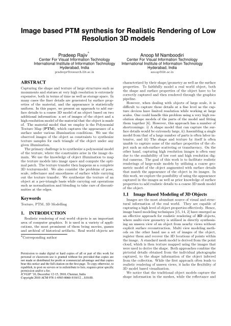
<strong>Image</strong> <strong>based</strong> <strong>PTM</strong> <strong>synthesis</strong> <strong>for</strong> <strong>Realistic</strong> <strong>Rendering</strong> <strong>of</strong> <strong>Low</strong>Resolution 3D modelsPradeep Rajiv ∗Center For Visual In<strong>for</strong>mation TechnologyInternational Institute <strong>of</strong> In<strong>for</strong>mation TechnologyHyderabad, Indiapradeepr@research.iiit.ac.inABSTRACTCapturing the shape and texture <strong>of</strong> large structures such asmonuments and statues at very high resolution is extremelyexpensive, both in terms <strong>of</strong> time as well as storage space. Inmany cases the finer details are generated by surface properties<strong>of</strong> the material, and the appearance is statisticallyuni<strong>for</strong>m. In this paper, we present an approach to add surfacedetails to a coarse 3D model <strong>of</strong> an object <strong>based</strong> on twoadditional in<strong>for</strong>mation: a set <strong>of</strong> images <strong>of</strong> the object and ahigh resolution model <strong>of</strong> the material that the object is made<strong>of</strong>. The material model that we employ is the PolynomialTexture Map (<strong>PTM</strong>), which captures the appearance <strong>of</strong> asurface under various illumination conditions. We use theobserved images <strong>of</strong> the object as constraints to synthesizetexture samples <strong>for</strong> each triangle <strong>of</strong> the object under anygiven illumination.The primary challenge is to synthesize a polynomial model<strong>of</strong> the texture, where the constraints arise in the image domain.We use the knowledge <strong>of</strong> object illumination to mapthe texture models into image space and compute the optimalpatch. The texture transfer then happens as a complete3D texturemodel. We also consider the problems <strong>of</strong> pose,scale, reflectance and smoothness <strong>of</strong> surface while carryingout the texture transfer. We synthesize the texture <strong>of</strong> anobject at a per-triangle basis while carrying out operationssuch as normalization and blending to take care <strong>of</strong> discontinuitiesat the edges.KeywordsTexture, <strong>PTM</strong>, 3D Modelling1. INTRODUCTION<strong>Realistic</strong> rendering <strong>of</strong> real world objects is an importantarea <strong>of</strong> computer graphics. It is used in a variety <strong>of</strong> applications,the most prominent <strong>of</strong> them being movies, gamesand archival <strong>of</strong> historical artifacts. Real world objects are∗ Corresponding authorPermission to make digital or hard copies <strong>of</strong> all or part <strong>of</strong> this work <strong>for</strong>personal or classroom use is granted without fee provided that copies arenot made or distributed <strong>for</strong> pr<strong>of</strong>it or commercial advantage and that copiesbear this notice and the full citation on the first page. To copy otherwise, torepublish, to post on servers or to redistribute to lists, requires prior specificpermission and/or a fee.ICVGIP ’10, December 12-15, 2010, Chennai, IndiaCopyright 2010 ACM 978-1-4503-0060-5/10/12 ...$10.00.Anoop M NamboodiriCenter For Visual In<strong>for</strong>mation TechnologyInternational Institute <strong>of</strong> In<strong>for</strong>mation TechnologyHyderabad, Indiaanoop@iiit.ac.incharacterized by their shape/geometry as well as the surfaceproperties. To faithfully model a real world object, boththe shape and surface properties <strong>of</strong> the object have to becorrectly captured and then rendered through the graphicspipeline.However, when dealing with objects <strong>of</strong> large scale, it isdifficult to capture these details at a fine level as the capturedevices have limited resolution while working at largescales. One could handle this problem using a very high resolutionshape models <strong>of</strong> the parts <strong>of</strong> the model and fittingthem together [6]. However, this approach has a number <strong>of</strong>shortcomings: i) A shape model that can capture the surfacedetails would be extremely large, ii) Assembling a singlemodel from that <strong>of</strong> a large number <strong>of</strong> parts is <strong>of</strong>ten labor intensive,and iii) The shape and texture by itself is <strong>of</strong>tenunable to capture some <strong>of</strong> the surface properties <strong>of</strong> the objectsuch as sub-surface scattering or translucency. On theother hand, capturing high resolution images is <strong>of</strong>ten easydue to the availability <strong>of</strong> low cost and high resolution digitalcameras. The goal <strong>of</strong> this work is to facilitate realisticrenderings <strong>of</strong> large-scale models by utilizing a coarse geometricmodel <strong>of</strong> the object augmented with surface detailsthat match the appearance <strong>of</strong> the object in its images. Inthis work, we explore the possibility <strong>of</strong> using the appearancecaptured in the images as well as prior knowledge <strong>of</strong> surfaceproperties to add realistic details to a coarse 3D mesh model<strong>of</strong> the object.1.1 <strong>Image</strong> Based Modeling <strong>of</strong> 3D Objects<strong>Image</strong>s are the most abundant source <strong>of</strong> visual and structuralin<strong>for</strong>mation <strong>of</strong> the real world. They are capable <strong>of</strong>capturing a high level <strong>of</strong> object properties effectively. Hence,image <strong>based</strong> modeling techniques [15, 14, 2] have emerged asan effective approach <strong>for</strong> realistic rendering <strong>of</strong> 3D objects,where multi-view geometry is utilized in directly synthesizingan unseen view <strong>of</strong> an object from nearby views withoutexplicit surface reconstruction. Multi view modeling methodson the other hand use a set <strong>of</strong> images <strong>of</strong> the object,register them and recover the 3D locations <strong>of</strong> points withinthe image. A standard mesh model is derived from the pointcloud, which is then texture mapped using the images thatwere used to derive the shape. Both approaches combine thepictorial details obtained from the individual photographscaptured, to the shape in<strong>for</strong>mation <strong>of</strong> the object inferredfrom the collection. While the first approach <strong>of</strong>ten leads torealistic rendering <strong>of</strong> unseen views, it lacks the flexibility <strong>of</strong>3D model <strong>based</strong> visualization.We notice that the traditional object models capture theshape in<strong>for</strong>mation in the meshes, while the reflectance and
surface properties are relegated to the texture. 3D texturemodels such as Polynomial Texture Maps (<strong>PTM</strong>s) [12] capturethe surface properties far more faithfully, including theeffects <strong>of</strong> small scale height variations on the surface. Hencethe combination <strong>of</strong> 3D texture models along with a coarsemodel <strong>of</strong> the object shape is capable <strong>of</strong> realistic rendering<strong>of</strong> objects. However, the acquisition <strong>of</strong> 3D textures such as<strong>PTM</strong>s is close to impossible in uncontrolled environments.In this work we look at synthesizing 3D textures on coarseobject models that retains the appearance characteristics <strong>of</strong>the captured images.Many texture <strong>synthesis</strong> algorithms [13, 7, 5, 17, 10, 4]have been developed to generate large samples <strong>of</strong> texturefrom scanned photographs. These methods are effective andmake the texture mapping process more efficient and robustby facilitating the generation <strong>of</strong> textures <strong>of</strong> any requiredsize. These have been later extended to texture 3D modelsand arbitrary manifold surfaces[16, 11, 18]. However, unliketraditional texture <strong>synthesis</strong>, where the goal is to generatea new texture patch that retains the characteristics <strong>of</strong> thesurface, we need to synthesize a 3D texture that agrees witha given image <strong>of</strong> the object in appearance. Be<strong>for</strong>e we lookinto the process <strong>of</strong> <strong>synthesis</strong>, we will explore some <strong>of</strong> thebasic aspects <strong>of</strong> 3D texture.(a)(c)(b)(d)Figure 1: <strong>Image</strong>s <strong>of</strong> a rough plaster surface obtainedunder varying light conditions. Note the change insurface appearance in each <strong>of</strong> (a), (b), (c) and (d)1.2 Reflectance Properties <strong>of</strong> Natural MaterialsThe visual characteristics <strong>of</strong> natural surfaces arise fromthe variation <strong>of</strong> two properties across its surface: i) the variationin normals, and ii) reflectance. These cause effects suchas shadows, self occlusions, inter reflections, and specularity,which affect the visual appearance <strong>of</strong> the surface. As aresult, a surface looks considerably different under differentlighting and viewing conditions. These effects are observedin all natural surface reliefs that are abundant in real world.Simple 2D texture models ignore these two properties <strong>of</strong>the natural textures. Hence they cannot model these variationsin visual appearance caused under varying illumination/viewingconditions. Moreover, in 2D texture mapping,the images that are texture mapped on to the 3D modelsinherently contain the lighting conditions under whichthey have been captured. Hence the texture model so obtainedlooks good in lighting conditions similar to that <strong>of</strong> theavailable images, but very poor when viewed under differentlighting conditions. Hence 2D texture mapping <strong>of</strong> 3D objectsis insufficient and falls short <strong>of</strong> accomplishing the task<strong>of</strong> realistic modeling and rendering real world objects.The characterization <strong>of</strong> surface reflectance properties isessential to achieve realistic rendering. The reflectance properties<strong>of</strong> a surface affects its appearance under different lightingand viewing conditions. This led to the study <strong>of</strong> relationbetween surface luminance and illumination/viewing conditions<strong>of</strong> natural material surfaces, and such models are <strong>of</strong>tenreferred to as 3D textures. This led to further investigationinto the problem <strong>of</strong> representation, recognition, <strong>synthesis</strong> <strong>of</strong>natural materials and their rendering under arbitrary viewing/lightingconditions [9]. <strong>Image</strong> <strong>based</strong> re-lighting techniques[12,3, 1] have been used to model the surface reflectanceproperties <strong>of</strong> the natural materials. In these techniquesmultiple images <strong>of</strong> the Object/surface are capturedunder different lighting/view point conditions and then thevariations in visual appearance modeled as Reflectance TextureMaps.1.3 Reflectance Texture MapsReflectance Texture Maps have emerged as the compactrepresentation <strong>of</strong> 3D textures. They model the spatial variationin surface luminance as a function <strong>of</strong> viewing and illuminationconditions. BTF(Bi-Directional Texture Functions)and UTF(Uni-Directional Texture Functions) are thetwo reflectance texture functions usually used to model thesurface reflectance properties <strong>of</strong> natural materials.Bi-Directional Texture Functions(BTF) [3] measures theratio <strong>of</strong> radiance L emitted at solid angle (φ 1, θ 1) to thatincident at a different solid angle (φ 2, θ 2) at a spacial location(u, v). BTF effectively captures all the complex phenomenalike shadows, specularities, self-occlusions, etc. However,the storage requirement <strong>of</strong> BTF is high and the generationis complex.Uni-Directional Texture Functions(UTF) are less exhaustivebut tractable representation <strong>of</strong> reflectance propertiesand confine themselves to the modeling <strong>of</strong> surface reflectanceproperties in relation to the lighting conditions. They donot consider the view point in surface intensity calculation.Hence they cannot model view point phenomenon such asspecularities. But they are easy to capture and do not requireany camera calibration. They require only a movablelight source and a stationary camera. UTF implicitlymodels surface normal in<strong>for</strong>mation. Hence surface normalscan be retrieved and then used to artificially introduce viewpoint phenomena at the time <strong>of</strong> rendering.Polynomial Texture Maps(<strong>PTM</strong>)[12] belonging to the class<strong>of</strong> UTF are a compact representation <strong>of</strong> reflectance textures.They model the surface luminance variations as aBi-quadratic polynomial function at each pixel <strong>of</strong> the texture.
Techniques to synthesize 2D textures on arbitrary shapedobjects[16, 11, 18] have also been extended to <strong>synthesis</strong> reflectancetexture maps on the same. In these techniques, the<strong>synthesis</strong> starts from an arbitrary patch and then it growson till the complete mesh-model is covered. The only constraintimposed on the <strong>synthesis</strong> process is that a patch tobe synthesized agrees with the already synthesized neighboringpatches. This constraint makes sure that no visibleseams appear on the textured model. Using these approaches,<strong>PTM</strong>s have been efficiently synthesized over 3Dmodels and rendered[8].The above mentioned 3D texturing algorithms when coupledwith image <strong>based</strong> modeling techniques provide an effectiveplat<strong>for</strong>m <strong>for</strong> realistic modeling <strong>of</strong> real world objects.Pictorial in<strong>for</strong>mation <strong>of</strong> the object can be obtained in a smallset <strong>of</strong> images and later used to constrain the texture <strong>synthesis</strong>procedure, which is otherwise unconstrained (except <strong>for</strong>inter-patch consistency). This hybrid approach provides aneffective way to synthesize the texture model <strong>of</strong> the object<strong>based</strong> on its appearance in the real world images. Hence itcan be employed to generate the 3D texture models <strong>of</strong> thereal world objects.We want to address this problem <strong>of</strong> constrained 3D texturing<strong>of</strong> mesh-models to make them more realistic and nearto their real world objects. Our goal is to capture a small set<strong>of</strong> images <strong>of</strong> the object under known lighting conditions, anduse these to systematically synthesize a <strong>PTM</strong> model <strong>of</strong> theobject from a sample <strong>PTM</strong> <strong>of</strong> the object’s material. Thesesparse set <strong>of</strong> images decide the sub-samples <strong>of</strong> the texturesample P T M in that are stitched across the mesh model sothat the resultant texture model would behave more similarto its real world counterpart.This work draws from the ideas <strong>of</strong> Efros et. al [4] <strong>for</strong>effective Texture transfer and the other that <strong>of</strong> Yacov Hel-Oret. al [8] <strong>for</strong> <strong>synthesis</strong> <strong>of</strong> 3D texture models <strong>for</strong> 3D objects.We present a method to effectively 3D texture the standardmesh model <strong>of</strong> a real world object from a sample <strong>PTM</strong> <strong>of</strong> itsmaterial using a small set <strong>of</strong> images captured <strong>of</strong> the objectunder different known lighting conditions as constraints, soas to make the model appear realistic and similar to theoriginal. The <strong>PTM</strong> model so generated can be efficientlyrendered under arbitrary lighting conditions.2. IMAGE BASED <strong>PTM</strong> SYNTHESISThe goal is to generate a 3D texture <strong>for</strong> a coarse meshmodel <strong>of</strong> a real world object, using a sample <strong>PTM</strong> <strong>of</strong> itsmaterial and a small set (atleast one) <strong>of</strong> images <strong>of</strong> the objectcaptured under different known lighting conditions. Theimages provide in<strong>for</strong>mation about the visual appearance <strong>of</strong>the object and make the <strong>synthesis</strong> process more effective inselection <strong>of</strong> subsamples that go into the making <strong>of</strong> the texturemodel. The resultant model not only appears realisticbut more similar to the original. The <strong>PTM</strong> model so generatedcan be efficiently rendered under arbitrary lightingconditions.2.1 Polynomial Texture MapsPolynomial Texture Map(<strong>PTM</strong>)[12] is a concise model <strong>of</strong>surface reflectance properties which can be used to introducephotorealism in the texture mapping process. Theyproperly model the real world phenomena such as self shadowing,inter-reflections, and sub-surface scattering, whichcause variations in the visual appearance <strong>of</strong> an object surfaceunder different lighting conditions. In order to synthesize a<strong>PTM</strong>, a set <strong>of</strong> images {I k } <strong>of</strong> the object surface are obtainedunder different light conditions {(lu k , lv k )}. These imagesamply capture the variations in the visual appearance <strong>of</strong> thesurface with changing light conditions and are used to buildthe reflectance model <strong>of</strong> the surface. The behavior at eachtexel is modeled independently with a reflectance functionthat encodes its behavior with respect to the lighting conditions.Hencethe <strong>PTM</strong> is parameterized on spatial location(u, v) and lighting position (φ, θ). Hence the Number <strong>of</strong>degrees <strong>of</strong> freedom is 4.The chromaticity <strong>of</strong> a pixel fairly remains constant underdifferent lighting conditions and it is only the luminance thatvaries. Hence only the luminance L(u, v) is modeled using<strong>PTM</strong>. The variations in luminance L at each pixel (u, v) isapproximated using a bi-quadratic polynomial given by:L(u, v; lu, lv) = a o(u, v)l 2 u + a 1(u, v)l 2 v + a 2(u, v)l ul v +a 3(u, v)l u + a 4(u, v)l v + a 5(u, v), (1)where L is the luminance at pixel (u, v) and (lu, lv) theprojection <strong>of</strong> a unit vector in the direction <strong>of</strong> the light sourceon the texture co-ordinate system. The luminance L(u, v)so obtained is modulated with the normalized color value(R n(u, v), G n(u, v), B n(u, v)) <strong>of</strong> the pixel to get the actualcolor.R(u, v) = L(u, v)R n(u, v)G(u, v) = L(u, v)G n(u, v) (2)B(u, v) = L(u, v)B n(u, v)The above representation is called LRGB <strong>PTM</strong> and ittakes advantage <strong>of</strong> the redundancy in surface color. At eachtexel (u, v) <strong>of</strong> the texture map, the coefficients (ao, . . . , a5)(u, v)<strong>of</strong> the corresponding bi-quadratic polynomial along with thenormalized color value (R n(u, v), G n(u, v), B n(u, v)) are stored.The luminance coefficients (ao, ..., a5)(u, v) <strong>of</strong> each texel areestimated, so as to fit the corresponding pixel data in theimages. Polynomial Texture Maps consisting <strong>of</strong> these surfaceluminance coefficients at each texel (u, v) approximatelymodel the behavior <strong>of</strong> the surface under different lightingconditions. The visual appearance <strong>of</strong> the object surface underarbitrary lighting conditions can be generated from thebi-quadratic approximation <strong>of</strong> L <strong>for</strong> each texel, given thelight vector (lu, lv).Patch <strong>based</strong> 2D texture <strong>synthesis</strong> techniques can be extendedto synthesize large patches <strong>of</strong> <strong>PTM</strong> from a giveninput sample and can also be extended to synthesize <strong>PTM</strong>son 3D models [8].2.2 Constrained <strong>PTM</strong> SynthesisGiven a <strong>PTM</strong> sample and a triangular mesh model <strong>of</strong>an object, small patches extracted from the sample can beseamlessly stitched across the mesh model and a <strong>PTM</strong> model<strong>of</strong> the object synthesized. The <strong>PTM</strong> model so synthesizedbehaves like a real world object in terms <strong>of</strong> its visual appearanceunder different lighting conditions. These patch<strong>based</strong> texture <strong>synthesis</strong> algorithms when coupled with image<strong>based</strong> modeling techniques provide an effective approachto synthesize the 3D texture models <strong>of</strong> real world objects.A set <strong>of</strong> images <strong>of</strong> the object captured varying light and
viewpoints decide the set <strong>of</strong> texture patches that are to bestitched across the mesh model. Hence the texture model soobtained not only looks realistic but also similar to its realworld counter part.We study the problem <strong>of</strong> generating a <strong>PTM</strong> model <strong>of</strong> areal world object by constraining the <strong>synthesis</strong> procedureusing the in<strong>for</strong>mation obtained from a set <strong>of</strong> images <strong>of</strong> theobject captured under known lighting conditions. Our workessentially builds on the work by Efros et. al [4] <strong>for</strong> TextureTransfer and the work by Yacov Hel-or et. al [8] <strong>for</strong> <strong>PTM</strong>modeling <strong>of</strong> 3D objects. We suggest an approach to generatethe reflectance texture model <strong>of</strong> a real world object from a<strong>PTM</strong> sample <strong>of</strong> the object material and a set <strong>of</strong> images <strong>of</strong>the object. We extended the patch <strong>based</strong> <strong>PTM</strong> <strong>synthesis</strong>algorithm to also include the image <strong>based</strong> in<strong>for</strong>mation ininfluencing the selection <strong>of</strong> the texture patches so as to makethe resultant texture model more similar to the object. The<strong>PTM</strong> model so obtained can be used to generate the views<strong>of</strong> the object under arbitrary lighting conditions.In the next section, we detail our method <strong>for</strong> <strong>PTM</strong> modeling<strong>of</strong> planar rectangular surfaces and then follow it up withanother section <strong>for</strong> the same on real world objects.B nB iB mBjBkInput Texture Sampleoverlapping regionOutput Texture<strong>Image</strong> Based Constraints(x,y) (x,y) (x,y)B kInput Set <strong>of</strong> <strong>Image</strong>sBmCandidate blocks <strong>for</strong> Overlapping ConstraintsFigure 2: Blocks from input sample are checked <strong>for</strong>image <strong>based</strong> and overlap constraints and the bestones are transferred to the output.2.3 <strong>Image</strong> constrained <strong>PTM</strong> <strong>synthesis</strong> <strong>for</strong> PlanarRectangular SurfacesIn this section we describe how the patch <strong>based</strong> 2D texture<strong>synthesis</strong> algorithm[10, 4] and <strong>PTM</strong> <strong>synthesis</strong> algorithm byYacov Hel-or et. al [8] is extended to synthesize the texturemodel <strong>of</strong> a planar rectangular surface from a sample <strong>PTM</strong><strong>of</strong> the surface material and a set <strong>of</strong> images <strong>of</strong> the surfacetaken under various known lighting conditions.A Polynomial Texture Map P T M out <strong>of</strong> the same dimensionsas the planar surface being modeled is generated asthe output <strong>of</strong> this procedure. The algorithm uses patchestaken from input sample P T M in as the building blocks tosynthesize the output texture P T M out. At each step k, acandidate block B k is taken from the input sample P T M inand stitched into the output texture P T M out. The selectedblocks are stitched into P T M out with an overlap W e betweenneighboring blocks and then blended in the overlappingregion. The texture map so obtained can be used togenerate novel views <strong>of</strong> the surface under arbitrary lightingconditions.The selection strategy <strong>of</strong> candidate block B k that is stitchedinto the output texture P T M out at every step is the core <strong>of</strong>our algorithm. The output texture P T M out is traversed ina raster scan fashion from left to right starting at lower leftcorner and moving upwards. At step k, a candidate block B kis selected to go into the next position (x, y). The selection<strong>of</strong> the patch B k is governed by two constraints namely:1 <strong>Image</strong> <strong>based</strong> constraints2 Overlapping constraintsThe set <strong>of</strong> images {I n} that are captured under varyinglight positions (l un, l vn) decide the candidate patches thatgo into the making <strong>of</strong> the output texture. The texture blockB k that is selected to go into the position (x, y) should agreewith the set <strong>of</strong> image blocks {b(I n, x, y)} that are covers theposition (x, y) in each <strong>of</strong> the images {I n}. Let the P T Mevaluation function be denoted by f(P, (l u, l v)), where Pis a P T M patch and (l u, l v) projection <strong>of</strong> unit light vectoron to the texture co-ordinate system. The P T M patchB k , when evaluated with the light vector (l un, l vn) correspondingto the image I n, should result in an image patchf(B k , (l un, l vn)) that matches the image block b(I n, x, y).Hence each image I n <strong>of</strong> the set {I n} imposes constraint onthe selection <strong>of</strong> the patch B k . These together constitutethe image <strong>based</strong> constraints involved in the <strong>synthesis</strong>. Eachtexture block B from the input sample P T M in is rankedaccording to a scoring measure S which is given as follows:S(B) =N∑‖f(B, (l un, l vn)) − b(I n, x, y)‖ 2 (3)n=1The blocks from the input sample P T M in are ranked accordingto the scoring mechanism S and a fraction <strong>of</strong> thetop candidates selected.At every step k <strong>of</strong> the <strong>synthesis</strong> procedure, the patch B kthat is selected to go into the output texture P T M out shouldalso agree with the patches {B 0, B 1, ...., B k−1 } that have s<strong>of</strong>ar been pasted in the previous steps. The candidate blockB k that is currently being pasted should agree with its neighboringpatches in the overlapping region. This constitutesthe overlapping constraint and is a must <strong>for</strong> seamless stitching<strong>of</strong> input blocks.The set <strong>of</strong> candidates that are selected <strong>based</strong> on image<strong>based</strong> constraints in step(1) are again ranked <strong>based</strong> on theiroverlapping measure. L2 norm is calculated over the difference<strong>of</strong> luminance coefficients in the overlapping regionbetween P T M out that has been synthesized so far and eachB <strong>of</strong> the candidate blocks picked by step(1). The norm iscalculated with the coefficients <strong>of</strong> both P T M out and blockB in the overlapping region trans<strong>for</strong>med to a orthogonalspace so that the distance between functions is same as thatbetween function coefficients. The block B k with minimalerror measure is introduced into the output P T M out.The complete algorithm is outlined as follows:Alpha-blending is usually employed to blend the texturecoefficients in the overlapping regions. The texture coefficientsare trans<strong>for</strong>med to an orthogonal space be<strong>for</strong>e blendingis employed. After blending, the coefficients are trans<strong>for</strong>medback by applying an inverse trans<strong>for</strong>mation.The above approach generates a better estimated <strong>PTM</strong>model <strong>of</strong> the given surface and it can be used to calculate
Algorithm 1 The Constrained <strong>PTM</strong> Synthesis Algorithm1: Traverse P T M out in a raster-scan order block by blockstarting at lower-left corner.2: At every new position (x, y), select a small set s <strong>of</strong> candidateblocks from P T M in using the image <strong>based</strong> constraints.3: Pick the best block B k among the set s which best fitsthe overlapping constraint.4: Paste the block B k at the location (x, y) in the outputtexture P T M out and blend it in the overlapping region.the appearance <strong>of</strong> the given surface under arbitrary lightingconditions.1(b)1(a)1(d)1(c)2(b)2(a)2(d)2(c)3(b)3(a)3(d)3(c)1(e) 2(e) 3(e)Figure 3: Demonstration <strong>of</strong> Our 2D Synthesis Algorithm<strong>for</strong> Natural Material Surfaces:. Top row, 1(a)-3(a),shows high resolution texture samples <strong>of</strong> three different rough plastersurfaces. <strong>Image</strong>s 1(b), 2(b), 3(b) are low resolution samples <strong>of</strong> surfacesabove and 1(c), 2(c), 3(c) shows the results <strong>of</strong> <strong>synthesis</strong> using images in(b) as constraint.Row 1(d)-3(d) are the textures synthesized at highresolution using images in (b) and 1(e)-3(e) shows the scaled versions <strong>of</strong>(b) <strong>for</strong> comparison.In Figure 3, we demonstrated the results <strong>of</strong> our 2D <strong>synthesis</strong>algorithm on three different surfaces. <strong>PTM</strong>s <strong>of</strong> variants<strong>of</strong> plaster surface were created from their high resolution images.<strong>Image</strong>s 1(a), 2(a) and 3(a) show the high resolutiontexture samples used in the creation <strong>of</strong> their correspondingsample textures. From a sparse set <strong>of</strong> low resolution images<strong>of</strong> an object and its sample <strong>PTM</strong>, the texture model <strong>of</strong> theobject was constructed and its views shown at the resolutionat which the object was captured as well as at a higher resolution.The material in<strong>for</strong>mation present at high resolutionaffirms our <strong>synthesis</strong> procedure.<strong>Image</strong>s 1(b), 2(b) and 3(b)are the object views captured at low resolution and 1(c), 2(c)and 3(c) represent the corresponding low resolution views <strong>of</strong>their texture models generated using our method. <strong>Image</strong>s1(d),2(d) ad 3(d) are the high resolution views <strong>of</strong> 1(c),2(c)and 3(c) respectively and 1(e),2(e),3(e) were obtained byscaling images 1(b), 2(b) and 3(b) respectively. Comparingthe results with the scaled versions, we note that while thesynthesized images has minor variations with the originalhigh resolution images (in a), the finer details visible in thesynthesized patches are missing in the plain scaled version.3. IMAGE CONSTRAINED <strong>PTM</strong> SYNTHE-SIS FOR REAL WORLD OBJECTSPatch-<strong>based</strong> 2D Texture Synthesis algorithms use squarepatches as the quilting blocks because <strong>of</strong> their simplicity towork with. The same cannot be said about <strong>synthesis</strong> <strong>for</strong> realworld objects which are 3D in nature. The 3D objects areusually represented with standard triangular mesh models.Triangle is the basic primitive <strong>for</strong> rendering 3D models.Hence it is more appropriate to consider triangle as the quiltingblock and texture map triangles rather than the usualsquare patches. But the triangles <strong>of</strong> the mesh model are<strong>of</strong> different sizes and shapes unlike the square patches usedin the previous section which are all <strong>of</strong> uni<strong>for</strong>m size. Itbecomes only difficult that all the triangles having varioustexture orientations.Considering all the above mentioned issues, we devisedan approach to synthesize image <strong>based</strong> <strong>PTM</strong> models <strong>of</strong> realworld objects. Given a set <strong>of</strong> images {I n} <strong>of</strong> the object capturedunder known light and camera positions {(l un, l vn), C n}and a texture sample P T M in <strong>of</strong> the object material, wesynthesize a texture model <strong>of</strong> the object by pasting triangularsubsamples taken from P T M in all across the triangularmesh model <strong>of</strong> the object. Like the earlier approach <strong>for</strong> planarsurfaces, this approach also considers the image-<strong>based</strong>constraints and overlapping constraints in selection <strong>of</strong> triangularpatches <strong>for</strong> the texture model.We outline the basic steps <strong>of</strong> our <strong>synthesis</strong> algorithm followedby a detailed description <strong>of</strong> each <strong>of</strong> them.Algorithm 2 <strong>PTM</strong> Synthesis <strong>of</strong> Real world Objects1: Assign each triangle T <strong>of</strong> the mesh model, an imageI k ∈ {I n} in which it is best visible and calculate itsmapping t in I k .2: Generate the normal view t n from t, find its best matchingtriangular texture patch p in P T M in and extract arectangular patch B containing p.3: Per<strong>for</strong>m Alpha-blending across every edge <strong>of</strong> the meshmodel, update the texture patches {B i} with blendedvalues.4: Extract the minimal bounding box b i contained insideB i <strong>of</strong> each triangular texture patch p i, and pack all suchb i into a number <strong>of</strong> texture atlases.3.0.1 Step1The object is imaged multiples times from different knownlighting directions and view-points {(l un, l vn), C n} to obtaina set <strong>of</strong> images {I n}. Each triangle T <strong>of</strong> the mesh model isthen mapped to an image I k ∈ {I n} in which it is best visible.The images in which the triangle T is completely visibleare picked and then an image I k among them in which it isbest visible is taken. The criteria <strong>for</strong> visibility is the anglemade by the normal n <strong>of</strong> the triangle T with the directional
vector <strong>of</strong> the camera C from its center. We rely on theassumption that each triangle T <strong>of</strong> the mesh model is completelyvisible in at least one image.The camera matrix M kcorresponding to the image I k is calculated and then usedto obtain the mapping t <strong>of</strong> triangle T in the image I k .3.0.2 Step2After step 1, each T is mapped to its best-view t in an<strong>Image</strong> I k . Now <strong>based</strong> on the angle θ between the normal n<strong>of</strong> T and the direction <strong>of</strong> the camera center C, the lengths<strong>of</strong> sides <strong>of</strong> the triangle in the normal view t n are obtainedusing the following <strong>for</strong>mulal in = l i/ cos θ, (4)where l i is the length <strong>of</strong> ith side <strong>of</strong> t in the image I k .The geometry <strong>of</strong> t n is determined by the sides {l in} andangles A, B, C <strong>of</strong> the original triangle T . For simplicity, theside connecting the first 2 vertices <strong>of</strong> t n is made parallel toX-axis. The color in<strong>for</strong>mation from t to t n is transferredusing a re-sampling algorithm.Calculate the local light vector l T with respect to a coordinatesystem placed at the centroid <strong>of</strong> T . The X-axis <strong>of</strong>this co-ordinate system aligns with the side connecting thefirst two vertices <strong>of</strong> T , Z-axis along the normal <strong>of</strong> T andY-axis decided by the <strong>for</strong>mer two.Evaluate the input sample P T M in using l T and searchthe resultant image <strong>for</strong> a set <strong>of</strong> patches {t′} which best agreewith t n. This constitutes the image <strong>based</strong> constraints. Eacht′ corresponds to a triangular texture patch p′ in the inputtexture sample P T M in.Now pick the best texture patch p ∈ {p′} which best agreeswith the texture patches <strong>of</strong> already processed neighboringtriangles {T j} <strong>of</strong> T . This constitutes the overlapping constraintimposed on the <strong>synthesis</strong>. In order to impose overlappingconstraints, at least one <strong>of</strong> the three neighbors <strong>of</strong>the current triangle T should have been already processed.Hence random processing <strong>of</strong> triangles <strong>of</strong> the mesh modelmight result in occasional weakening <strong>of</strong> the selection strategyand the quality <strong>of</strong> texture model so obtained.To prevent this, the triangles <strong>of</strong> the mesh model are processedin a Breadth-First-Search(BFS) order. By doing so,overlapping constraints are imposed in the selection <strong>of</strong> texturepatch p <strong>for</strong> every triangle T <strong>of</strong> the mesh model except<strong>for</strong> the first one.For each triangle T i, a minimal bounding box b i surroundits triangular texture patch p i is identified and a bigger rectangularpatch B i containing b i surrounded by a extra texelstrip (5 to 10 texels) all around is extracted from the texturesample P T M in. The extra strip <strong>of</strong> texels is used <strong>for</strong>blending with texture patches <strong>of</strong> neighboring triangles.3.0.3 Step3Each <strong>of</strong> the above mentioned boxes B i include an extrastrip <strong>of</strong> W e on all the 4 sides <strong>of</strong> the corresponding minimalbounding box b i. This strip is essentially used <strong>for</strong> alphablendingacross edges. The extra texel padding around theactual triangular texture is blended with the border in<strong>for</strong>mation<strong>of</strong> neighboring triangle as shown in Figure 4. Thealpha-blended in<strong>for</strong>mation is written back to the set <strong>of</strong> boxes{B i}3.0.4 Step4Minimal bounding boxes {b i} are extracted from {B i} byT 1W e W eT 2T 1T2b1b2B1B2Red region inside T 1gets blended with Blue region <strong>of</strong> T 2Figure 4: Blending <strong>of</strong> neighboring triangles. Redregion <strong>of</strong> T1 blends with blue region <strong>of</strong> T2 and viceversa.cutting <strong>of</strong>f the extra strip <strong>of</strong> texels present around. These{b i} are then packed in to a number <strong>of</strong> atlas maps <strong>of</strong> desireddimensions W and H using any <strong>of</strong> the standard bin-packingalgorithms. The texture mapping co-ordinates <strong>of</strong> all thetriangles T i are updated all along the procedure and thefinal mapping co-ordinates with respect to the <strong>PTM</strong> atlases{P j} are stored.The above process <strong>of</strong> <strong>PTM</strong> <strong>synthesis</strong> <strong>for</strong> a real world objectis an <strong>of</strong>f-line process. Hence we limit ourselves to onlythe <strong>synthesis</strong> procedure and not the time complexity, techniquesto speed it, etc.3.1 <strong>Rendering</strong> <strong>of</strong> the <strong>PTM</strong> ModelThe <strong>PTM</strong> model <strong>of</strong> the object obtained can be efficientlyrendered at run time to generate novel views <strong>of</strong> the real worldobject under different lighting conditions. In this procedure,each triangle T is considered separately and the position <strong>of</strong>light with respect to it calculated. The unit vector (lu T , lv T )so obtained is used to evaluate its <strong>PTM</strong> patch p to generatean image patch. Hence we get image atlases correspondingto the set <strong>of</strong> <strong>PTM</strong> atlases. These image atlases are used astexture objects, loaded and the textured model rendered.4. EXPERIMENTAL RESULTS AND ANAL-YSISWe demonstrate our 3D <strong>synthesis</strong> algorithm on a set <strong>of</strong>rough surface models created using displacement mapping.Synthetic 3D textures and object models are used so thatthe same texture model can be used to generate surface textures<strong>for</strong> the mesh model. We generated a height map andapplied it individually on the plane surface, a smooth sphereand a cylinder using displacement mapping to create roughobjects. A sample <strong>PTM</strong> is then created using a set <strong>of</strong> images<strong>of</strong> the rough planar surface. A small set <strong>of</strong> images <strong>of</strong> therough sphere and cylinder were taken to provide the image<strong>based</strong> constraints. These images and the sample <strong>PTM</strong> wereused to construct the <strong>PTM</strong> models <strong>of</strong> the rough sphere andthe cylinder. In Figure 5, the images (a), (b) and (c) show
(a) View1: Rough Planar Surface (b) View2 (c) View3(d) Rough Sphere (e) View1: Textured SphericalMesh(f) View2(g) Rough Cylinder(h) View1: Textured CylindricalMesh(i) View2Figure 5: Synthesis Results <strong>for</strong> 3D object:<strong>Image</strong>s (a), (b) and (c) show three different views <strong>of</strong> a rough planarsurface. <strong>Image</strong>(d) shows a rough sphere and (e),(f) show two views <strong>of</strong> the textured mesh model that was generated.Likewise images (g),(e) and (f) show the same <strong>for</strong> a cylinder <strong>of</strong> similar texture.
three views <strong>of</strong> a rough plane and these are used to constructthe texture sample employed in <strong>synthesis</strong>. <strong>Image</strong>s (d) and(g) show a rough sphere and a cylinder created using displacementmapping. <strong>Image</strong>s (e) and (f) show two arbitraryviews <strong>of</strong> the constructed <strong>PTM</strong> model <strong>of</strong> the rough sphere andimages (h) and (i) show the same <strong>for</strong> the rough cylinder.As we note, the synthesized model is able to capture thesurface properties, as the lighting directions change, whichwould be impossible in the case <strong>of</strong> 2D textures. Moreover,as seen from <strong>synthesis</strong> <strong>of</strong> the planar object, the synthesized3D texture generates images resemble the observed images<strong>of</strong> the original object.However, there are primarily two issues that still remainto achieve photo-realistic rendering <strong>of</strong> 3D mesh models: i)The <strong>PTM</strong> model itself does not handle shadows and specularitiesin the texture well as it creates an overly smoothapproximation <strong>of</strong> the transition from light to shadows withchange in light direction, ii) Variations in appearance withlighting direction is accentuated at the triangle boundaries.Currently we are working on developing improved models <strong>of</strong>the <strong>PTM</strong> to handle the first issue, and with <strong>synthesis</strong> techniquesthat directly create smooth transitions over triangleboundaries.5. CONCLUSION AND FUTURE WORKWe demonstrated an image <strong>based</strong> texture <strong>synthesis</strong> techniqueto effectively synthesize reflectance textures <strong>for</strong> materialsurfaces and objects. We developed the idea <strong>of</strong> transferringtexture on to the mesh models <strong>of</strong> real world objects torealistically reproduce the natural visual appearance, perceptionand their interaction with the lighting environment.Polynomial texture maps implicitly contain the surfacenormal in<strong>for</strong>mation. We are presently working on artificiallyintroducing viewpoint phenomenon such as specularities inthe rendering <strong>of</strong> <strong>PTM</strong>s <strong>of</strong> 3D models <strong>of</strong> real world objects.We also want to investigate the idea <strong>of</strong> manipulation <strong>of</strong> luminancecoefficients in influencing the visual perception <strong>of</strong>shape in<strong>for</strong>mation <strong>of</strong> the object surface, so that the seamsthat occur at the join <strong>of</strong> adjacent patches can be effectivelyremoved and smooth transitions introduced in place.6. REFERENCES[1] M. Ashikhmin and P. Shirley. Steerable illuminationtextures. ACM Trans. Graph., 21(1):1–19, 2002.[2] A. Baumberg. Blending images <strong>for</strong> texturing 3dmodels. In Proc. Conf. on British Machine VisionAssociation, pages 404–413, 2002.[3] K. J. Dana, B. van Ginneken, S. K. Nayar, and J. J.Koenderink. Reflectance and texture <strong>of</strong> real-worldsurfaces. ACM Trans. Graph., 18(1):1–34, 1999.[4] A. Efros and W. T. Freeman. <strong>Image</strong> quilting <strong>for</strong>texture <strong>synthesis</strong> and transfer. In SIGGRAPH ’01:Proceedings <strong>of</strong> the 28th annual conference onComputer graphics and interactive techniques, pages341–346, New York, NY, USA, Aug. 2001. ACM.[5] A. Efros and T. Leung. Texture <strong>synthesis</strong> bynon-parametric sampling. In International Conferenceon Computer Vision, pages 1033–1038, 1999.[6] M. L. et al. The digital michelangelo project: 3dscanning <strong>of</strong> large statues. In Proceedings <strong>of</strong>SIGGRAPH, pages 131–144, New Orleans, LA, USA,2000.[7] D. J. Heeger and J. R. Bergen. Pyramid-<strong>based</strong> textureanalysis/<strong>synthesis</strong>. In SIGGRAPH ’95: Proceedings <strong>of</strong>the 22nd annual conference on Computer graphics andinteractive techniques, pages 229–238, New York, NY,USA, 1995. ACM.[8] Y. Hel-Or, T. Malzbender, and D. Gelb. Synthesis andrendering <strong>of</strong> 3d textures. 3rd International Workshopon Texture Analysis and Synthesis, 2003.[9] T. Leung and J. Malik. Representing and recognizingthe visual appearance <strong>of</strong> materials usingthree-dimensional textons. International Journal OnComputer Vision, 43(1):29–44, 2001.[10] L. Liang, C. Liu, Y. Xu, B. Guo, and H. yeung Shum.Real-time texture <strong>synthesis</strong> by patch-<strong>based</strong> sampling.ACM Transactions on Graphics, 20:127–150, 2001.[11] S. Magda and D. Kriegman. Fast texture <strong>synthesis</strong> onarbitrary meshes. In SIGGRAPH ’03: ACMSIGGRAPH 2003 Sketches & Applications, New York,NY, USA, 2003. ACM.[12] T. Malzbender, D. Gelb, and H. Wolters. Polynomialtexture maps. In Computer Graphics, SIGGRAPH2001 Proceedings, pages 519–528, 2001.[13] K. Popat and R. W. Picard. Novel cluster-<strong>based</strong>probability model <strong>for</strong> texture <strong>synthesis</strong>, classification,and compression. In Visual Communications and<strong>Image</strong> Processing, pages 756–768, 1993.[14] C. Rocchini, P. Cignoni, C. Montani, and R. Scopigno.Multiple textures stitching and blending on 3dobjects. In Eurographics <strong>Rendering</strong> Workshop, pages119–130. Springer-Verlag, 1999.[15] M. Soucy, G. Godin, R. Baribeau, F. Blais, andM. Rioux. Sensors and algorithms <strong>for</strong> the construction<strong>of</strong> digital 3-d colour models <strong>of</strong> real objects. pages II:409–412, 1996.[16] G. Turk. Texture <strong>synthesis</strong> on surfaces. InSIGGRAPH ’01: Proceedings <strong>of</strong> the 28th annualconference on Computer graphics and interactivetechniques, pages 347–354, Aug. 2001.[17] L.-Y. Wei and M. Levoy. Fast texture <strong>synthesis</strong> usingtree-structured vector quantization. In SIGGRAPH’00: Proceedings <strong>of</strong> the 27th annual conference onComputer graphics and interactive techniques, pages479–488, New York, NY, USA, 2000. ACMPress/Addison-Wesley Publishing Co.[18] L.-Y. Wei and M. Levoy. Texture <strong>synthesis</strong> overarbitrary manifold surfaces. In SIGGRAPH ’01:Proceedings <strong>of</strong> the 28th annual conference onComputer graphics and interactive techniques, pages355–360, New York, NY, USA, 2001. ACM.


