QSDT4PCRC and QSDT8PCRS_web.pdf - Q-See
QSDT4PCRC and QSDT8PCRS_web.pdf - Q-See
QSDT4PCRC and QSDT8PCRS_web.pdf - Q-See

You also want an ePaper? Increase the reach of your titles
YUMPU automatically turns print PDFs into web optimized ePapers that Google loves.
SYSTEM REQUIREMENTS ANDSPECIFICATIONS2.1 SYSTEM REQUIREMENTSNOTE! If recorded disk partition’s format is FAT32 <strong>and</strong> the system has runfor a long time, the system will create a lot of data fragments that may resultin system running slowly. It’s recommended to run a disk defragmenter every10 to 30 days. We strongly suggest that you use NTFS format for recording disk partition.CardPC Module<strong>QSDT4PCRC</strong>CPUIntel P4 2.8G minimum or later Intel processorMotherboard Intel with Intel system chipsetHard Drive 250GB minimumRAM1GB minimumSupports MOST* AGP <strong>and</strong> PCI-E Video CardsVideo Card with 128MB of RAM or more with full Direct Draw support.*Some newer PCI-E cards are not yet supportedOS Windows XP (SP2 <strong>and</strong> above), Windows Vista, Windows 7DirectX 9.0CardPC Module<strong>QSDT8PCRS</strong>CPUIntel P4 2.8G minimum or later Intel processorMotherboard Intel with Intel system chipsetHard Drive 500GB minimumRAM1GB minimumSupports MOST* AGP <strong>and</strong> PCI-E Video CardsVideo Card with 256MB of RAM or more with full Direct Draw support.*Some newer PCI-E cards are not yet supportedOS Windows XP (SP2 <strong>and</strong> above), Windows Vista, Windows 7DirectX 9.0CHAPTER 22.2 SYSTEM SPECIFICATIONSFormat: NTSC /PALResolution: 320x240 / 640x480 (NTSC), 320x288 / 640x576(PAL)Maximum Frame rate per channel: 30 fps (NTSC), 25 fps (PAL)Screen set: resolution 1024×768, color quality 16 bits or 32 bits.Compression code rate: 50kbps – 1.2Mbps.Data format: H.264 (files saved as AVI)ComponentSpecificationInput TypeD typeVideo Input<strong>QSDT4PCRC</strong>: 4 Cameras <strong>QSDT8PCRS</strong>: 8 CamerasDisplay Rate (per channel) 30fps (NTSC), 25 fps (PAL)Recording Rate (perchannel)320x240: 30fps (NTSC) 640x480:7.5fps (NTSC)/320x248:25fps (PAL), 640x576: 6.25 fps (PAL),Compression Format H.264 SoftwarePlayback Resolution 320x240, 640x480(NTSC), 320x288, 640x576 (PAL)Recorder MediaHDD, USB Disk, ZIP, CD-R/W via PCRecord ModeMotion/Sensor/Schedule/ManualNetworkTCP/IPI/O Device Alarm <strong>QSDT4PCRC</strong> 4 Ch Sensor Input, 1 Ch Relay Output (on board)<strong>QSDT8PCRS</strong> 8 Ch Sensor Input, 1 Ch Relay Output (on board)Audio <strong>QSDT4PCRC</strong> 4 Channels on Dongle<strong>QSDT8PCRS</strong> 8 Channel Inputs on DonglesPTZProtocol Configurable, Remote Control CapabilityRemote Software Supports Internet Explorer Web BrowserInterfacePCICHAPTER 2 SYSTEM REQUIREMENTS AND SPECIFICATIONSNOTE! We do not recommend AMD systems because the SuperDVRprogram usually has problems communicating with the video card on thesystem through the chipset on the AMD motherboard. There are often similarproblems with Intel processors on motherboards that use chipsets other then Intel, <strong>and</strong>there are known issues with the Intel G31 chipset.10 11
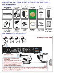
VIDEO CAPTURE CARDHARDWARE AND CONNECTIONS3.1 <strong>QSDT4PCRC</strong> CARD HARDWARECHAPTER 3SPOT OUTThe Spot Out feature allows you to send selected video channels to a separate monitor.Menus <strong>and</strong> controls will not display in this monitor. If you do not wish to use this feature thenyou do not have to attach this port.Alarm PortSpot Out PortAudio In PortsPICTURE 3-1Spot Out with Multiple CardsIn situations where multiple cards areinstalled, only one card can provide the signalto the remote monitor.Link the con2 to con1 ports on the cards,with the last card linking to the Spot Out porton the face plate.PICTURE 3-3AUDIOYou will only need to install the Audio dongle if you have audio-equipped cameras,microphones or other audio input devices.Use of this dongle will take up an additionalI/O port on the computer.The audio connector’s pins are mapped outin Picture 3-4.PIN1 AUDIO-1 PIN2 GNDPIN3 AUDIO-2 PIN4 GNDPIN5 AUDIO-3 PIN6 GNDPIN7 AUDIO-4 PIN8 GNDJ5GiL-G-8P-S3T2-E12345678CallMonitorOutCHAPTER 3 VIDEO CAPTURE CARD HARDWARE AND CONNECTIONSPICTURE 3-4Video In DongleVIDEOThe video dongle connects to the 15-pinreceiver on the card. The four video inputsuse BNC connectors to interface with thecamera leads.VideoVideoVideoVideoNot UsedNot UsedNot UsedNot Used123456789101112131415GroundPICTURE 3-2PICTURE 3-512 13
3.2 <strong>QSDT8PCRS</strong> CARD HARDWARESPOT OUTThe Spot Out feature allows you to send selected video channels to a separate monitor.Menus <strong>and</strong> controls will not display in this monitor. If you do not wish to use this feature thenyou do not have to attach this port.Video- <strong>and</strong> Audio-In Dongles (2)PICTURE 3-6Alarm PortSpot Out PortSpot Out with Multiple CardsIn situations where multiple cards areinstalled, only one card can provide the signalto the remote monitor.Link the con2 to con1 ports on the cards,with the last card linking to the Spot Out porton the face plate.PICTURE 3-8VIDEO AND AUDIO PIN LAYOUTVideo <strong>and</strong> audio input is provided through the two dongles which attach to the two 15-pinreceivers on the card. Each dongle supports four channels of video <strong>and</strong> four channels ofaudio.P4PinPIN 11 2 VIDEO-5 3 4 5 6 7 8GNDVideo 4GNDVideo 3GNDVideo 2GNDVideo 12 GNDP2 P4 P1 Pin ConnectionConnection3 VIDEO-64 GND5 VIDEO-7GNDNullAudio 4Audio 3Audio 2Audio 1GND6 GND7 VIDEO-8PIN 9 10 11 12 13 14 158 GND9 GND10 AUDIO-511 AUDIO-612 AUDIO-713 AUDIO-814 NULL15 GNDPIN 1 2 3 4 5 6 7 8GNDVideo 8GNDVideo 7GNDVideo 6GNDVideo 5GNDNullAudio 8Audio 7Audio 6Audio 5GNDPIN 9 10 11 12 13 14 15P3 P2PIN 1 2 3 4 5 6 7 8GNDVideo 4GNDVideo 3GNDVideo 2GNDVideo 1GNDNullAudio 4Audio 3Audio 2Audio 1GNDPIN 9 10 11 12 13 14 15P31 VIDEO-12 GND3 VIDEO-24 GND5 VIDEO-36 GND7 VIDEO-48 GNDP1CallMonitorOut9 GNDPIN 1 2 3 4 5 6 7 810 AUDIO-1GNDVideo 8GNDVideo 7GNDVideo 6GNDVideo 511 AUDIO-212 AUDIO-313 AUDIO-414 NULLGNDNullAudio 8Audio 7Audio 6Audio 5GND15 GNDPIN 9 10 11 12 13 14 15CHAPTER 3 VIDEO CAPTURE CARD HARDWARE AND CONNECTIONSPICTURE 3-7PICTURE 3-914 15
3.3 ALARM PORTInstall this dongle only if you wish to use external alarm sensors. The DVR card has built-inmotion detection software which can be used to trigger alarms when motion is detected by acamera.Use of this dongle will take up an additionalI/O port on the computer.To connect an alarm, you will need to attacha DB25 25-pin male solder cup <strong>and</strong> solderthe wires from the alarm to the cup. The pinorder is shown in Picture 3-10.3940PICTURE 3-10123.4 CONNECTING A PTZ CAMERAIn order to operate a PTZ camera from your computer, you will need to have first installed thecard into a PCI slot within the computer <strong>and</strong> attached the video dongle.You will also need an RS485 to RS232 (Serial) adapter as well as having a serial port on theback of your PC.PTZ CameraRS485 toSerial Adapter2PCPins highlighted in yellow in the chart below are only used by the <strong>QSDT8PCRS</strong>.Pin Port Define Interpret Pin Port Define InterpretPin1 Alarm_in1 Alarm Input 1 Pin21Pin2 Alarm_in2 Alarm Input 2 Pin22Pin3 Alarm_in3 Alarm Input 3 Pin23Pin4 Alarm_in4 Alarm Input 4 Pin24Pin5 Alarm_in5 Alarm Input 5 Pin25Pin6 Alarm_in6 Alarm Input 6 Pin26Pin7 Alarm_in7 Alarm Input 7 Pin27Pin8 Alarm_in8 Alarm Input 8 Pin28Pin9Pin29Pin10Pin30Pin11Pin31Pin12Pin32Pin13Pin33Pin14 Pin34 Alarm_Com Alarm COMPin15 Pin35 Alarm_NO Alarm Normal OpenPin16 Pin36 GND GroundPin17 Pin37 GND GroundPin18 Pin38 5V Power Source (5V)Pin19 Pin39 Alarm_NC Alarm Normal ClosePin20Pin4013 4PICTURE 3-11STEP 1. Connect the RS485 cables from the PTZ camera to the RS485-to-Serial AdapterSTEP 2. Connect the Adapter to the serial port on the back of the PCSTEP 3. Connect the video line from the camera to any Video In port on the DVR card(Item 4)You may now connect your camera to a power source.Please see Chapter 8 for instructions on operating the PTZ camera with the SuperDVRsoftware.CHAPTER 3 VIDEO CAPTURE CARD HARDWARE AND CONNECTIONS16 17
BASIC OPERATION CHAPTER 5 5.2 DISPLAY CONTROL PANELWhen you launch the SuperDVR program, it will open to the Main Display Interface whichwill show the video feeds from the cameras as well as the Display Control Panel.1The Display Control Panel includes the Display Mode buttons along with buttons which allowyou to cycle automatically or manually through individual or groups of channels.Buttons currently in effect are highlighted.The Drive Capacity Indicator Bar will fill in asmore files are recorded to the drive. When thedrive is at capacity, the bar will be red.PICTURE 5-32345 6 7 8 9PICTURE 5-1No. Item No. Item1 Display Window 2 Record Status Panel3 Display Modes 4 Display Control Panel5 Dwell Time 6 Page Flip7 Drive Capacity Indicator Bar 8 Snapshot9 Urgent Record 10 Date <strong>and</strong> Time11 Login 12 Emap13 Search <strong>and</strong> Playback 14 Configurations15 PTZ Control 16 Exit10111213141516DISPLAY MODESChoose the number of channels you wish to view simultaneously. If you have fewer camerasthan portions of the screen, those channels without cameras will remain black.Available modes are single-, four-, nine-. 16-<strong>and</strong> 36-screen displays. The software will onlydisplay the modes appropriate to the numberPICTURE 5-4of cameras you have connected.AUTO DWELL DISPLAYIf the Main Display is currently showing fewer channels than are available, you can have theDVR automatically cycle through <strong>and</strong> show the feed from each camera or group of camerasby selecting the button.PAGE FLIPThis button allows you to manually cycle through the channels. Like the Auto Dwell feature, ifthere are more channels available than are currently being displayed in a multi-screen displaymode, this button will take you to the next group of video feeds.CHAPTER 5 BASIC OPERATION5.3 OTHER CONTROLSLog In will be covered in the following section <strong>and</strong> the remaining operations on the lefth<strong>and</strong> side of the Main Display Interface will be covered in Chapter 7. The two remainingfunctions are Snapshot <strong>and</strong> Urgent Record.5.1 LOG INLocated on the left side of the Main DisplayInterface, clicking on the lock icon will openthe Login window. Enter your user name <strong>and</strong>password to access the controls. The defaultuser name is System with no passwordrequired. You can add a password <strong>and</strong> createother user accounts as described in Section7.4 User Configuration.SNAPSHOTUsable in single image display mode, pressing this button will take a series of still imagesfrom the camera currently being displayed <strong>and</strong> will save them to a location on the hard drive.Settings to determine the number of images (up to 32) as well as the location to where theywill be saved will be covered in Chapter 6.URGENT RECORDClicking the Urgent Record icon will cause all cameras to begin recording regardless of theirschedule or recording mode. Video will be saved to the location designated by the user. LikeSnapshot, the settings for this feature will be covered in Chapter 6.PICTURE 5-222 23
RECORDING, PLAYBACK ANDRECORD SEARCHCHAPTER 66.1 RECORDING CONFIGURATIONThe system can be set to record in four different modes; scheduled recording, manual recording,motion detection <strong>and</strong> sensor alarm.Once you have logged into your system, you can access the control settings through theConfiguration window by clicking on the wrench icon located on the left of the Main DisplayInterface.Upon accessing the Configuration window, the icons on the left will change as will the contentsof the Display Window.BASIC CONFIGURATIONThe Record Panel, in the bottom half of the Basic Configuration page, allows users to setrecording modes along with other parameters for each camera. More than one recordingmode can be activated at one time.It should be noted that the higher the recording quality <strong>and</strong> frame rate, the more space therecorded file(s) will occupy on the hard drive.Basic ConfigurationVideo configurationAlarm ConfigurationUser ConfigurationPICTURE 6-1Schedule configurationMotion Detection ConfigurationP.T.Z ConfigurationSave <strong>and</strong> ReturnPICTURE 6-2Time Stamp - By selecting this option, the record date / time message appears in therecorded file images.Switch - Turns on corresponding cameras. If there is no camera on a channel, do not selectthis option <strong>and</strong> you will save system resources.Manual Record - Images from the selected camera will be recorded <strong>and</strong> saved all the time(24 hour recording).Manual Recording Frame Rate - Select the recording frame rate for manual record mode.Schedule Record - This option allows you to record on a set schedule.Schedule Record Frame Rate - Select Schedule Recording frame rate.Motion Detection - By selecting this option, users can set the selected channels to recordwhen motion is detected in front of the camera.Motion Record Frame Rate - Select recording frame rate for Motion Detection record mode.Sensor Record Frame Rate - If sensors are utilized to trigger recording, users can selectrecording frame rate here.Camera Security - Users are divided into three types: Normal user, Power user <strong>and</strong>Administrator. By selecting this option, only administrators can see the selected channels.Record Quality - Select recording image quality here.Audio In - SuperDVR 6.3 can support one channel of microphone audio input signal on thePC motherboard <strong>and</strong> any audio inputs that are on the card if any. Users can choose one videochannel for each available audio input.CHAPTER 6 RECORDING, PLAYBACK AND RECORD SEARCHFor the purposes of this chapter, we will only be concerned with; Schedule Configuration,Video Configuration <strong>and</strong> Motion Detection Configuration. The remaining functions will becovered in Chapter 7.24 25
RECORD STATUS PANELA series of indicator lights will convey the recording status of each attached camera.PICTURE 6-3Grey Normal Light Green Manual RecordDark Green Schedule Record YellowIf an indicator light color turns, it means there is an alarm output.Motion DetectionRecordRed Sensor Alarm Record Blue Video Loss State6.2 RECORDING MODESAs mentioned at the beginning of this chapter, there are four different recording modes;scheduled recording, manual recording, motion detection <strong>and</strong> sensor alarm. Motion Detectionrecord mode <strong>and</strong> Sensor Alarm record mode are called Alarm Record.If users use multiple cameras to record, every camera works separately <strong>and</strong> the recorded filesare also saved separately. The parameters, i.e. camera ID, record date/time, <strong>and</strong> record modeare all saved together with the recorded file.MANUAL RECORD MODEManual Record mode is the most commonly used recording mode. If a special event occurs,users can select this recording mode <strong>and</strong> record immediately. It may be desirable to increasethe framerate <strong>and</strong> recording quality in such cases - especially for shorter duration recordings.If you intend to have the cameras recording non-stop, then it is advisable to reduce the framerate to conserve hard drive space.SENSOR ALARM RECORD MODEUsers can use sensors to trigger sensor alarm recording on relative channels. At that time, therecord status indicator light will turn red.MOTION DETECTION RECORD MODEThis will enable the system to detect image changes <strong>and</strong> begin to record by activating motiondetection <strong>and</strong> motion alarm recording. For instance, somebody opens the door, <strong>and</strong> thesystem detects image changes from the camera <strong>and</strong> begins to record, then users can playback the recorded file <strong>and</strong> find out who opened the door. When there is no movement, thesystem will not record which saves system resources, <strong>and</strong> makes it easier to find recordedevents. The indicator light color in the record status panel will be yellow.Configuring Motion DetectionSelecting the running man icon will bring up the Motion Detection Configuration page,where you can configure the settings for each camera according to your situation.Sensitivity - Users can set motion detectionsensitivity here.Speed - Motion detection speedBlock Number - Set grid’s number.Defaults - Reset to default settings.Select All - Select the entire area of thechannel as detection sensitiveClear - Clear all the detection areas <strong>and</strong> thenyou can select a customized detection areausing the cursor.PICTURE 6-4To customize the detection area for a certain channel:STEP 1. Select the camera in the pull down list.STEP 2. Select ClearSTEP 3. Click <strong>and</strong> drag the cursor in the camera view. You will see a green box appearwhich shows the motion detection area. You can select a maximum of 16 customizedareas for each channel.SCHEDULE RECORDINGUsers can set working schedule for all of the recording modes in ‘Schedule Configuration’.The dark green light in record status panel shows the corresponding channel is in ScheduleRecord mode. Users can change record mode to manual record at any time, <strong>and</strong> the darkgreen light will change into a light green light.Schedule ConfigurationClicking on the calendar icon willchange the display window to theSchedule Configuration page.Each camera can be scheduled to recordbased on motion detection, sensor alarm,<strong>and</strong> time of day. Sensor alarm mode hashighest priority <strong>and</strong> it will take precedenceregardless of what other modes the camerais also set for.PICTURE 6-5CHAPTER 6 RECORDING, PLAYBACK AND RECORD SEARCHNOTE! When configuring for Motion Detection recording, you will need todo so in three areas:1. Select Motion Detection for the desired channels in Basic Configuration.2. Configure the specific areas to detect motion in Motion DetectionConfiguration.3. Set the schedule for these cameras to operate in this mode in Schedule Configuration.26 27
Schedules can be set individually for each day. The cameras are default configured tobe recording in both Motion Detection <strong>and</strong> Schedule recording 24/7 <strong>and</strong> will have fulllengthcolored bars in the schedule window. Above each window is a 0-24 with segmentscorresponding to each hour of the day. This will show when a camera has been scheduled torecord in that mode.NOTE! When setting up your recording schedule for the first time, it is faster<strong>and</strong> easier to begin by selecting the mode’s schedule window <strong>and</strong> selectingDelete All to clear the schedule before making changes.To create a new schedule;STEP 1. Select the camera name in oneof the three record mode groups.STEP 2. Click on Add.6.3 RECORDING TO HARD DRIVEUsers can determine where recorded files will be saved on their hard drive(s). In addition,the recorder can save to a series of drives or partitions by automatically jumping to the nextpartition when the current one is full. If all the partitions are full <strong>and</strong> Recycling Record modehas been enabled prior to recording by checking the box below the Storage Disk list, the newdata will overwrite the oldest recorded data automatically.The destination drive(s) for recordings -which also applies to images captured usingthe Snapshot button - is set in the BasicConfiguration window. You can also seta HDD minimum storage alarm which willcause the system to alert you once the thatthreshold has been reached. If the presentstorage space is less than the minimumstorage needed <strong>and</strong> Recycling Recordings isnot selected, the recording will automaticallystop.STEP 3. This will open a new window.Set the start time <strong>and</strong> end time alongwith the day(s) to which you wish theschedule to apply.STEP 4. Click OK to exit the Addwindow.PICTURE 6-6PICTURE 6-7Your new schedule will appear as a series of colored bars corresponding to the day(s) <strong>and</strong>time(s) you’ve selected.To edit a schedule, select a block of time <strong>and</strong> click Edit. You will be able to adjust theschedule for that day <strong>and</strong> any other day in the same manner you used to create the schedulein the Add window.PICTURE 6-8WARNING! You should have your files record to a disk or partition OTHERthan your “C” drive. This will avoid issues with the Recycling function.CHAPTER 6 RECORDING, PLAYBACK AND RECORD SEARCHNOTE! When adding a new schedule, it should not duplicate an existingschedule as this may cause a system error.To add another block of time, such as an evening recording schedule to go with an earlymorning schedule, you will need to repeat the process.Clicking on Delete will remove a specific block of time from a specific day’s schedule.Copy To allows you to apply the settings for one camera to another camera as well.28 29
6.4 RECORD SEARCH AND PLAYBACKClicking the Search icon in the lower right of the Main Display Interface will cause it toswitch to the Search <strong>and</strong> Playback Interface. This interface h<strong>and</strong>les both the RecordSearch <strong>and</strong> Playback functions in addition to allowing you to back up your records.RECORD SEARCHSearches are based on date <strong>and</strong> time. Additional criteria can be selected to narrow thesearch. These criteria include the type of the recording <strong>and</strong> where the files are saved.STEP 1. Select whether the programshould search in the normaldestination location (<strong>See</strong> Section6.3 Recording to Hard Drive)<strong>and</strong>/or where you’ve backed uprecorded files (Covered in Section6.5 Other functions)STEP 2. Select the nature of therecording - whether it was ascheduled record, recorded as aresult of motion detection or etc. Youcan select more than one category.PICTURE 6-10PICTURE 6-9Pressing the back arrow in the upper right of the display will return you to livesurveillance in the Main Display Interface.STEP 3. Enter the date <strong>and</strong> time. Acalendar will pop up. If there was anevent recorded on that date it will behighlighted.PICTURE 6-11CHAPTER 6 RECORDING, PLAYBACK AND RECORD SEARCHSTEP 4. The program will display thesearch results at the bottom of thescreen. They will be color coded toindicate the mode in which they wererecorded.PICTURE 6-1230 31
DELETING RECORDED FILESWhile older files will get overwritten by the Recycling Recording function as the hard drivefills up, you can delete unnecessary or unwanted recordings before then.Pressing the Snapshot button will bring up the Snap window.Number of Framesto be CapturedSnapshotShowTitleShowTimeSelectSave PathThis function will delete a file or blocks offiles from a specific camera or which wererecorded during a set time.Select the channel on the left side, <strong>and</strong> thenthe select start date <strong>and</strong> time <strong>and</strong> end date<strong>and</strong> time of the files you wish to delete.Click Start to delete files.You can also remove files manually bydeleting them from the folder where they arestored, just as with any other PC file.PICTURE 6-17CAPTURE PICTURESThis feature allows you to capture still images from a recorded event so they can be saved orprinted out.When the Search <strong>and</strong> Playback Interface is displaying only a single channel <strong>and</strong> the userhits the Play/Pause button a second time to pause playback, then the video is in PlaybackPause mode.At this time the function buttons above theFile Search panel will be enabled.PICTURE 6-18Snapshot Print setup Print pictureNOTE! This feature is only available in Playback Pause mode on a singlechannel.In addition, a second menu will appear below the Search panel. This allows you to makepicture quality adjustments for the present channel, including brightness, contrast, saturation<strong>and</strong> hue.These changes will not affect the actualrecorded image. Pressing the Default iconin the lower right of the panel will restore theoriginal settings.Make the desired adjustments to the image<strong>and</strong> then select the Snapshot icon.PICTURE 6-20Select the number of sequential images you wish to capture <strong>and</strong> set the save path. The savepath can also be set in the Basic Configuration menu in the Capture Browse setting. Youcan also chose to include which camera took the video <strong>and</strong>/or the date <strong>and</strong> time that it wasrecorded within the image itself.Once you have made your selections, pressing the Snap button will save the images. PressSave to preserve your settings for future use or Exit, if you do not wish to retain the settings.The Print Setup button will bring up aconventional Print Setup window to allow youto make settings as normal.Clicking the Print button will open a PrintPreview dialog that includes some extrafeatures.Select the Position radio button <strong>and</strong> adjustthe position of the image on the page usingthe + <strong>and</strong> - buttons.Selecting the Size radio button will allow youto adjust the image size using those same +<strong>and</strong> - buttons.PICTURE 6-21CHAPTER 6 RECORDING, PLAYBACK AND RECORD SEARCHPICTURE 6-1934 35
DIGITAL IMAGE ZOOMDuring multi-screen playback, clicking on one channel will cause the display to shift to a singlechannel display mode.While in single channel playback mode thedigital zoom controls are enabled. Theseallow you to zoom in or out of an area of therecording.PICTURE 6-22SYSTEM SETTINGS CHAPTER 7Beyond the recording settings, there are other features of this video capture card which needto be enabled or configured.The Settings window is entered by clicking on the wrench icon on the left of the Main DisplayInterface.Zoom InZoom OutRevert to original sizePICTURE 7-1CHAPTER 7 SYSTEM SETTINGSBasic ConfigurationSchedule configurationVideo configurationMotion Detection ConfigurationAlarm ConfigurationP.T.Z ConfigurationUser ConfigurationSave <strong>and</strong> Return36 37
7.1 BASIC CONFIGURATIONYour card is pre-configured with default settings which meet the needs of most users,however it is designed to allow you maximum flexibility in configuring the system to meet yourspecific needs.In the upper portion of the Basic Configuration window are settings which control additionalaspects of your cameras. We have already covered the recording-specific settings in theprevious chapter.CAMERA DISPLAY SETTINGSDwell IntervalIf you have enabled Auto Dwell function on the main interface page, then you can set thedwell time, in seconds, of a screen here.CaptionThere are four options, None, ID, Name,<strong>and</strong> ID/Name for users to select for all thechannels.‘None’ means no title or name;‘ID’ means camera numbers, i.e. 1, 2, 3<strong>and</strong> so on;‘Name’ means camera names, i.e.Cam1, Cam2 <strong>and</strong> so on;‘ID/Name’ means both camera number<strong>and</strong> camera name, i.e. 1/Cam1, 2/Cam2 <strong>and</strong> so on.PICTURE 7-2ResolutionYou may have resolution options of 320×240, 640x480, or 704x480 (NTSC) for users to selectfor all the channels depending on the card you are using.Call MonitorYou can connect another monitor to the Spot Out port on the card <strong>and</strong> select the displaymodes here.SYSTEM LOG IN AND REBOOTYou can enter your User Name <strong>and</strong> Password that you use to log into Windows so that theSuperDVR can log in upon startup or reboot.Since the windows system may becomeunstable after a couple of days of continuousoperating, it may cause SuperDVR tobecome unstable. You can use the softwaresupport auto-reboot option to help avoid this.PICTURE 7-3Select the PC Auto Reboot tab in the centerof the Basic Configuration screen <strong>and</strong> thencheck the box next to PC Auto Reboot <strong>and</strong>set the interval by day, which will cause thesystem to reboot automatically according toyour schedule.VIDEO CONFIGURATIONClicking on the video configuration icon will open a new page which will allow you tochange the contrast, brightness, hue, saturation <strong>and</strong> auto gain of individual cameras, bymoving the levers on the bars. Clicking Default will restore the default values.The range of values is from 0 to 255.Contrast - Set image color contrast.Brightness - Set image brightness.Hue - Set image hue.Saturation - Set image SaturationPICTURE 7-4CHAPTER 7 SYSTEM SETTINGS38 39
7.2 ALARM CONFIGURATIONThe system can receive alarm signals generated both by attached devices as well asfrom those from over a network. Alarms can also be generated when motion is detected.TRIGGERED ACTIONSEach type of alarm can be configured to generate an audible alarm - externally or internally, aswell as triggering other, pre-defined actions.PICTURE 7-7Buzzer - Select whether to activate the computer buzzer if alarms have been triggered <strong>and</strong>also select how long the buzzer sounds.Pre-Alarm Record - Select whether the system will pre-record <strong>and</strong> for how long.Big Screen Holding Time - The corresponding channel will be full screen when an alarm istriggered. Set the full screen hold time here.Motion Holding Time - How long the recording continues after motion stops.Sensor Holding Time - How long the recording continues after sensor stops.Disk Shortage Alarm - If the Partition free space is less than the set percent, the system willstop recording or recycling, but will sound an alert according to the settings.Alarm RecordEvery sensor can trigger multiple channels to record. For example: if CAM1, CAM4 <strong>and</strong> CAM5are selected for Sensor2, then once the sensor is activated, CAM1, CAM4 <strong>and</strong> CAM5 willbegin to record.PICTURE 7-5ALARM TYPESDifferent conditions can be set to trigger an alarm.Video Loss - Users can select alarm outputfor this option.For example: If you select alarm_out1 <strong>and</strong>alarm_out3 for video loss. Then video loss ofany channel will trigger alarm_out1, alarm_out3 to show a red light in the Alarm outputstatus panelDisk Alarm - When HDD available space isless than the set value, it will trigger alarm.Sensor - If users have mounted sensors,when the sensors have been activated, it willtrigger the selected output alarms.Motion - Users can set the output of motiondetection alarm by different alarms <strong>and</strong>remote alarm.PICTURE 7-6CHAPTER 7 SYSTEM SETTINGSUsers can also select the voltage (high or low) for alarm signals.40 41
Auto MailAny of the alarm types can be configured to generate an alert e-mail but it is especially usefulwhen triggered by a motion detection event.If Attachment is enabled,then a picture ofwhat triggered the alarm will be sent to theselected mailbox.NOTE! Before configuring the Auto Mail function, be sure to set up MotionDetection.Click the Auto Mail icon on the left top side of alarm configuration page to enter the AutoMail Setup Interface.PICTURE 7-10NOTE! Only one picture will be attached for each alarm event.7.3 E-MAP CONFIGURATIONE-map is used to show full geographic range covered by the whole monitoring system in theform of map. An E-map features simple operation <strong>and</strong> direct display of status.NOTE! The system only supports bmp or jpg image format for E-Map files.Users can set receiving <strong>and</strong> sending E-mailSMTP server <strong>and</strong> address. The addressof receiver <strong>and</strong> sender can be the same.However, this is not recommended as it canoverflow your e-mail account. Some freee-mail providers also place a daily limit onthe number of e-mails sent <strong>and</strong> received by asingle account.To test the settings, click Send Mail Test.If all settings are okay, response ‘MessageSent Successfully’ will pop up. If somesettings are wrong, a warning message willpop up.PICTURE 7-8Sender's E-mail AddressSender's SMTPReceiver's E-mail AddressPICTURE 7-9Sender's User NameE-mail SubjectSender's PasswordYou will need to draw the floor plan of whereyou want to install the cameras in a programsuch as Paint or Photoshop <strong>and</strong> save it inBMP or JPG format before using this feature.Files will be proportionally scaled to 833x678pixels when in use.Click on Emap Edit <strong>and</strong> then right-click inthe demonstration map currently displayed.Select Load Picture in the pop-up. Navigateto where the image is stored on yourcomputer <strong>and</strong> open the file. The map will bedisplayed in this interface, allowing you toadd the cameras to the map.Drag the icon of a camera to thecorresponding position on the map, amaximum of 32 cameras can be setsimultaneously, Click Change icon of cameraby right key to change icon or click Delete tocancel a camera. After editing, right-click inthe map display area <strong>and</strong> select Save Map inthe pop-up to save the current map.PICTURE 7-11PICTURE 7-1242 43CHAPTER 7 SYSTEM SETTINGS
ADD USERClick Add in User Configuration to accessthe Add User area.Enter the user name, password, confirmpassword <strong>and</strong> select user rights, <strong>and</strong> thenclick OK.Delete UserSelect the user name in UserConfiguration, <strong>and</strong> click Delete, <strong>and</strong>confirm delete.PICTURE 7-16P.T.Z. CAMERAS CHAPTER 8If you are installing a PTZ camera, then the PTZ controls must be set up before operating thecamera. You should have your PTZ camera’s manual h<strong>and</strong>y when configuring <strong>and</strong> operatingthe PTZ camera for the first time. You should have the information regarding the Baud Rate,Protocol <strong>and</strong> Address ready before you begin.8.1 P.T.Z CONTROL CONFIGURATIONThe PTZ settings are found in the Configuration menu. Click on the wrench icon on theright side of the Display Interface to enter the Configuration menu <strong>and</strong> then click on thePTZ menu to configure its settings.PICTURE 7-17PROTOCOL SETUPYou can select different protocols, serial portnumber for P.T.Z devices.The settings you enter here must match thesetting on the PTZ camera.PICTURE 8-1CHAPTER 8 P.T.Z. CAMERASPort - Users can set serial port number.Protocol - Communication protocol of theP.T.Z device.SuperDVR supports the following protocols:DSCP, DH-SD, Lilian, Minking, Neon, PelcoD,PelcoP, Star, VIDO, VISCAAddress - Communication address of P.T.Zdevice (ID number)PICTURE 8-246 47
SERIAL PORTS SETUPUsers should first enable the P.T.Z control function of a camera <strong>and</strong> then select a port numberin P.T.Z Protocol Setup. The values entered for each parameter should match those on thecamera itself.Port - Set the port number.Baud Rate - Set P.T.Z device Baud Rate tomatch setting on camera. The defaultvalue is 9600.Data Bits - Default value is 8.Parity - Odd <strong>and</strong> even parity bit, defaultNone.Stop Bits - The Default value is 1.PICTURE 8-38.2 PTZ OPERATIONThe PTZ Controls can be accessed directly from the Main Display Interface by clickingon the PTZ Control icon on the right side of the display. This will replace the buttons <strong>and</strong>functions on the right side of the display with the PTZ controls.Clicking on Set PTZ speed allows you toadjust the Pan Speeds, Tilt Speeds, FocusSpeeds <strong>and</strong> Zoom Speeds for all connectedPTZ cameras.Pan Speed - Set horizontal rotating speed.Tilt Speed - Set vertical rotating speed.Focus Speed - Set camera focus speed.Zoom Speed - Set zoom in/ zoom outspeed.Click <strong>and</strong> a pop-up window willappear; users can choose different presets orgroup sets.PICTURE 8-6PICTURE 8-7You can control P.T.Z. devices by clicking onits display. The selected camera channel willbe highlighted in red indicating that it is readyto be controlled.Focus, Zoom <strong>and</strong> Iris (light level) are adjustedby the use of the + <strong>and</strong> - keys to either side.A PTZ function (direction, zoom, etc.) willcontinue as long as the user is holding downthe left mouse button while the cursor is overthe button or until it reaches a physical limit.PICTURE 8-4PICTURE 8-5PRESET AND GROUP SELECTClick to set Preset point <strong>and</strong>change Preset point name. Every Groupincludes multiple Preset points. If usersselect preset1, preset2 <strong>and</strong> preset3 forgroup1, preset1, preset2 <strong>and</strong> preset3 will beautomatically accessed in sequence afterusers select group1 for auto scout.PresetClick, <strong>and</strong> a pop-up willappear allowing you to configure settings fora Preset.Dwell- Set the dwell time for a Preset. Thecamera will wait this long before moving on tothe next action.PICTURE 8-8PICTURE 8-948 49CHAPTER 8 P.T.Z. CAMERAS
PART 2: DETERMINE THE NUMBER OF ROUTERS ON THE NETWORKTo find out the number of routers on your network, you will need to download a FREE routerdetection program.STEP 6. If there is only one router detected, then you may skip to Part 3: Simple PortForwarding.STEP 1. Go tohttp://www.pcwintech.com/shanes-toolboxSTEP 2. Click on Detect MultipleRouters to begin the download.If Multiple Routers are DetectedIf there are multiple routers, you will see adisplay similar to Picture 9-8.If so, it may be preferable to connect yourDVR <strong>and</strong> computer to the router thatconnects directly to the Internet. However, thisis not always possible depending upon yourparticular situation.STEP 3. Unzip the application to install it.STEP 4. Click on the detect_routersapplication to run it.PICTURE 9-5PICTURE 9-8In this case, you will need to proceed with the next section using the IP address for Router 1to forward its ports. After that, you will need to proceed to Part 4.PICTURE 9-6STEP 5. Click on CHECK NOW todetect how many Routers are in thenetwork.CHAPTER 9 REMOTE SURVEILLANCE & PLAYBACKPICTURE 9-752 53
PART 3: SIMPLE PORT FORWARDINGDownload the FREE Simple Port Forwarding program from:http://www.simpleportforwarding.com/downloadSTEP 5. Click on ADD CUSTOM.STEP 1. Click on Download in any of the mirrors or the Direct Download link to download<strong>and</strong> install this program.PICTURE 9-9STEP 2. Once the program is installed,go to the Windows Start Menu(Windows icon in the lower left ofyour monitor) <strong>and</strong> look for SimplePort Forwarding in the program list.Click on the program to launch it.STEP 6. Input the required information:PICTURE 9-12PICTURE 9-10STEP 3. Once Simple Port Forwarding has launched, select your router from the list.The default Router IP <strong>and</strong> Login information will automatically come up. If you havepreviously changed the login information, then you will have to enter it manuallyName: (You can name your DVR if youwish)Type: TCPStart Port: 80End Port:80IP add: IP of DVR obtained inPart 1.Click on ADDRepeat for port 1159 <strong>and</strong> 1160.PICTURE 9-13CHAPTER 9 REMOTE SURVEILLANCE & PLAYBACKPICTURE 9-11STEP 4. Click on “+” at the bottom to open the window allowing you to set your ports.54 55
STEP 7. You will now be returned to the main window of the program. The ports youadded will now show on the list. Click on Update Router at the bottom.If for some reason, a port or ports that you forwarded are not listed in the Router <strong>and</strong> if yousee a message in the Scripts list on the left side of the window stating that the port alreadyexists (Red box in Picture 9-16), then you will need to change the Port 80 to 85 in the DVR<strong>and</strong> start over again.PICTURE 9-16PICTURE 9-14STEP 8. You will see the “Updating is in progress” message. Please wait until you see itsay DONE at the bottom.STEP 9. Once you receive the DONE message that the ports have been successfullyforwarded, test if the ports are working by clicking on item number 7 in the CheckList - Test that the ports now work.PICTURE 9-15PICTURE 9-17CHAPTER 9 REMOTE SURVEILLANCE & PLAYBACK56 57
STEP 10. Click on Begin.If you receive a message stating that the port is online <strong>and</strong> can be reached, then you haveset it up correctly.PART 4: SETTING UP DMZ IN ROUTER 2NOTE! You will only need to proceed with this section if you detected asecond router in Section 2.PICTURE 9-18To connect to your DVR from the Internet, you will need to put the Internet IP address shownafter “Your Internet Address:” message into your Internet Explorer browser or access programwindow.NOTE! The default value is 80. If port 80 is already occupied by another deviceon the network, then another port will need to be selected. Choose anothernumber in the same range; 81-89. In this case, you will have to add the port tothe IP address when entering it into the Internet Explorer window. For example,if the port is now 82, then you will need to enter http://192.168.0.25:82IMPORTANT! Do not use 255 or higher to complete your IP address as theseaddresses are reserved for other devices <strong>and</strong> components.STEP 1. Login into Router 1 by puttingthe IP of Router 1 into the InternetExplorer browser, as in the exampleshown in Picture 9-19 where the IPaddress of Router 1 is 192.168.0.1STEP 2. Find the status page on therouter settings that shows the WAN/Internet IP address <strong>and</strong> write it downthis WAN IP address.STEP 3. Log into the Router 2 by puttingthe IP of Router 2 into the InternetExplorer browser, as in exampleshown in Picture 9-19 where the IPaddress of Router 2 is 192.168.1.1STEP 4. Find the DMZ page in the routersettings.STEP 5. Enter the WAN IP for Router 1into the DMZ page <strong>and</strong> enable DMZ.PICTURE 9-19NOTE! If you do not have a DMZ setting in the router, check to see if thereis a Bridge setting. If so, then use the Bridge setting instead of DMZ.STEP 6. Save your changes.You have forwarded the ports on the router to which the DVR is connected, to the IP addressof the DVR, <strong>and</strong> set the primary router to pass the connection to this router.CHAPTER 9 REMOTE SURVEILLANCE & PLAYBACK58 59
9.3 DDNS (DYNAMIC DOMAIN NAME SERVICE)You can access the system over the Internet using a static or dynamic IP address. However,your service provider can change this dynamic address from time to time. When it changes,you will have to return to www.MyIPAaddress.com to get the new public IP address.There are two solutions to this problem. The first would be to obtain a static IP address fromyour ISP – which can be expensive. A second – <strong>and</strong> free – option is to use a dynamic domainname service (DDNS) to get a domain name that can be linked to your dynamic IP address. Inaddition to automatically keeping up with the changes in the address, you will now be able toenter a domain name rather than a string of digits when accessing the DVR in Internet Explorer.We recommend using www.MyQ-<strong>See</strong>.com or www.DynDNS.com as the DVR has beenalready configured to accept account information from these two services.NOTE! Before setting up DDNS, you must have previously set up PortForwarding as described in the previous section.9.4 ACCESSING THE DVR USING INTERNET EXPLOREROnce you have configured the network settings on the DVR to match those on your router<strong>and</strong> forwarded the ports needed by the DVR to enable remote access over the Internet, youwill be ready to remotely view your cameras using a <strong>web</strong>cam program based on an ActiveXcontrol. For this to work, you will have to enable the ActiveX control options that are built intoInternet Explorer. It is strongly suggested that you be running the latest version of InternetExplorer (currently IE8). The instructions below will describe the process using that version ofthe browser. Instructions for users with IE6 or 7 are available in the Resources library of ourTechnical Support page.USER ACCOUNT CONTROL FOR WINDOWS VISTA AND WINDOWS 7Some users of computers using Windows Vista or Windows 7 operating systems may receivean error message informing of a codec that is missing or not installed. This conflict can beresolved by turning off User Account Control (UAC).SETTING UP DDNSThe following instructions are for setting up DDNS with MyQ-<strong>See</strong>, instructions for DynDNS areavailable on their <strong>web</strong>site.STEP 1. Using a computer that isconnected to the same router as theDVR, use Internet Explorer to go towww.MyQ-<strong>See</strong>.comWindows VistaSTEP 1. Open the Control Panel(accessible by clicking on theWindows icon in the lower left of yourscreen.PICTURE 9-23STEP 2. Fill out the required informationto register <strong>and</strong> click the Submitbutton at the bottom of the screen.STEP 2. Select User Accounts <strong>and</strong>Family Safety.STEP 3. The next page will ask youto create a domain name. Domainnames must begin with a letter (a-z)or a number (0-9) <strong>and</strong> cannot containa hyphen. Once you’ve decidedupon a name, click on the “RequestDomain” button. If it is available youwill see a confirmation screen alongwith the IP address associated with it.Confirm that this matches the numberobtained in Network Settings. Yourdomain name will look like this:http://example.myq-see.comSTEP 4. Once you have obtained yourdomain name, you will need toconfigure the DVR for access using it.PICTURE 9-20PICTURE 9-21STEP 3. Select “Add or Remove UserAccount.”STEP 4. Select the desired user account.PICTURE 9-24PICTURE 9-25CHAPTER 9 REMOTE SURVEILLANCE & PLAYBACKSTEP 5. Once you have completed steps 1-4, click on the link on the MyQ-<strong>See</strong> <strong>web</strong>siteto download the MyQ-<strong>See</strong> software program onto your computer <strong>and</strong> install it so thatit can monitor the IP address assigned to your account. The computer must always beon in order to update the link to the public IP address when it changes.PICTURE 9-2660 61
STEP 5. Select Turn User AccountControl on or offPICTURE 9-27Setting Up ActiveX ControlSTEP 1. Open Internet ExplorerSTEP 2. Click on ToolsSTEP 3. Select Internet Options in thepull-down menuSTEP 6. Uncheck the box next to “UseUser Account Control (UAC) to helpprotect your computer.”PICTURE 9-32STEP 4. Click on the Security TabSTEP 5. Select Trusted SitesSTEP 7. You will then be asked to restartyour computer for the change to takeeffect.STEP 6. Click on the Sites buttonPICTURE 9-33Windows 7STEP 1. Open up the Start Menu(accessible by clicking on theWindows icon in the lower left of yourscreen.STEP 2. Type “uac” into the search bar<strong>and</strong> hit ENTER. The User AccountControl will open or you will be offereda link to click to open it.STEP 3. Move slider to lowest setting<strong>and</strong> press OK.PICTURE 9-28Microsoft Office Outlook 2007Devices <strong>and</strong> PrintersSticky NotesDefault ProgramsiTunesHelp <strong>and</strong> SupportAdobe AcrobatAll ProgramsuacShut downPICTURE 9-29STEP 7. Uncheck the “Require serververification (https:) for all sites inthis zone” button.STEP 8. Type the DVR’s IP address(obtained during Network Setup)or DDNS domain name into the “Addthis <strong>web</strong>site to the zone:” box.STEP 9. Click the Add buttonSTEP 10. Close the window.PICTURE 9-34CHAPTER 9 REMOTE SURVEILLANCE & PLAYBACKPICTURE 9-3162 63
STEP 11. Click the Custom level…button.STEP 13. Click the Reset buttonSTEP 14. Click “Yes” when asked, “Areyou sure you want to change thesetting for this zone?”STEP 15. Click OKSTEP 16. Click ApplySTEP 17. Click OKSTEP 18. Close Internet ExplorerPICTURE 9-37PICTURE 9-35You are now ready to access the DVR using Internet Explorer.STEP 12. Pull down the “Reset to:”menu button <strong>and</strong> select LowPICTURE 9-36Open a browser window in Internet Explorer<strong>and</strong> enter the IP address or DDNS name(obtained in Section 9.3 DDNS (DynamicDomain Name Service)) into the addressbar.You will see a log in screen similar to thatshown in Picture 9-38 or yellow alert bar atthe top of the window asking for permissionto open an ActiveX application. Allow it toinstall <strong>web</strong>rec.cab control to reach thesign-in screen.Instructions for controlling your systemremotely are in the next section.PICTURE 9-38CHAPTER 9 REMOTE SURVEILLANCE & PLAYBACK64 65
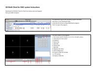
ACCESSING THE INTERNET EXPLORER CLIENTAfter enabling network server on the unit, <strong>and</strong> enabling ActiveX, users can view the videofrom the cameras over the LAN or Internet through Internet Explorer. This unit only supportsInternet Explorer browser, no other browsers are supported. It also supports Win2000, WinXP,Vista, <strong>and</strong> Win7.Input the IP address of the computer with the card if accessing from LAN, or the public IPaddress of the router if accessing from the internet, into the Internet Explorer window to reachthe window that prompts you to install the ActiveX control.You will get a message asking you to installthe file NetVideo.cab. Install it as normal.IconDescriptionControls for PTZ Cameras: Move Up. Move Down.Move Left rotate left. Move Right. Stop Rotating.PTZ ‘Focus’ buttons. Far Focus Near FocusPTZ ‘Zoom’ buttons. Zoom In Zoom OutPTZ ‘Iris’ button. Increase light. Decrease lightGo to a Preset PointSet a Preset PointSpeed dome. Adjust PTZ speed.Single channel with full screen displayPICTURE 9-39Four channel mode - four cameras displayedYou will then be asked to log in. Use thesame User Name <strong>and</strong> Password as youwould when logging in from the computeritself. The default User Name is SYSTEMwithout a password.Contrast adjustmentBrightness adjustmentHue adjustmentSaturation adjustmentOnce you have entered the User Name <strong>and</strong>Password, click OK to log in.As you can see, theWebCam main interfaceis very similar to theSuperDVR main interface.PICTURE 9-40Log in/ Log outRecord playbackSystem ConfigurationLAN or Master stream is for users on the same network asyour system. It has higher frame rate <strong>and</strong> needs higher networkb<strong>and</strong>widthInternet, or sub stream, has a lower frame rate <strong>and</strong> requireslower network b<strong>and</strong>width. Users can select the streamaccording to their b<strong>and</strong>width.CHAPTER 9 REMOTE SURVEILLANCE & PLAYBACKPICTURE 9-4166 67
Right-clicking the mouse in the main interfacewill open a sub menu.9.5 REMOTE PLAYBACKRECORD PLAYBACK AND CONTROLOpen Stream - Click this item, selectedchannel will openClose Stream - Click this item, selectedchannel will closeClose All - Click this item, all channels willcloseFull Screen - Select this item, the picturewill display full screen. Double click orclick right mouse to return to the previousinterface.PICTURE 9-42Clickbutton on the Webcam maininterface, <strong>and</strong> the remote playback interfacewill appear:PICTURE 9-43Play/ PauseStopAdjust the speed of playing back. Users can adjust play speed as needed.Playing back backup. Users can click Backup to enter into the RemoteBackup interface:REMOTE BACKUPSTEP 1. Select the date, channel, thenclick Search button. It will list all filesrecorded for the day.STEP 2. Click Browse button, set thesaving path.STEP 3. Select files in the search area.Users can hold shift button on thekeyboard <strong>and</strong> select multi files withmouse simultaneously.STEP 4. Click Backup button to doremote backup.PICTURE 9-44The backup files will be saved in AVI format. Most computer users can play with most thirdparty players directly.If you do not have a media player installed, we suggest using Windows Media Player Classicwhich is available as a free download from many <strong>web</strong> sites <strong>and</strong> is easily found via an onlinesearch.CHAPTER 9 REMOTE SURVEILLANCE & PLAYBACK68 69
Right-clicking the mouse in the search areawill open a sub menu.PICTURE 9-45If you want to view all channels, click Select all, then all check boxes before channels will beselected.Click Clear all to clear all selected channels; if users select a certain channel, click Select thischannel, then just this channel be selected.Click Clear this channel to deselect that channel.The ruler on top of the bar shows the hours of the day. Right-click the ruler, it will be magnified10 times allowing users to see the time marks more clearly.When searching for a certain section of a record, draw the bar to the desired position. Ifnecessary, right-click the bar to see the magnified time marks for precise search.You can click the Play button to play the selected record, Then return to live display mode afterfinishing remote playback, it will display a message ‘Connecting…’on the screen. And youmay click “Large Picture” or “Quad Picture” button to refresh the screen to get live picture.Return to previous main interfaceMultiple Channels playback controlThe system default playback modesare single <strong>and</strong> four channel. If you needto change to other channels, then clickthe single channel button to bring up the1-channel configuration window where youcan select one channel from all the availablechannels for playing back.PICTURE 9-46The four channel configuration windowwill display when the four channel iconis selected allowing you to select any fourchannels from all the available channels forplay back.PICTURE 9-47Data preview shows the recorded data for different channels during corresponding time, theleft side shows the available channels. When a certain channel has been selected for playingback, the background color will be highlighted, or its dark gray <strong>and</strong> a tick sign will appearbeside the channel title.PICTURE 9-48The data preview area at the center gives details of the recorded files. Different colors of thebar show different types of records.CHAPTER 9 REMOTE SURVEILLANCE & PLAYBACKBLUE Manually Recorded GREEN Schedule RecordedYELLOW Motion Detection RED Sensor Alarm70 71
9.6 SYSTEM SETUPClick <strong>and</strong> enter the main setup interface.Server PC SetupYou can enter the user name <strong>and</strong> passwordfor the computer which houses the videocapture card in the appropriate boxes. Thisway, when the computer system restarts, itwill access to the system with the user name<strong>and</strong> password input in these boxes to beginrunning the SuperDVR application.PICTURE 9-51As the Windows system may become unstable after a couple of days of continuous operation.It may cause the SuperDVR system to become unstable. The software supports auto-reboot.Select PC Autoreboot <strong>and</strong> set the interval by day, which will instruct the system to rebootautomatically according to your settings.PICTURE 9-49ALARM SETUPThe Alarm setup configuration is similar to that in the SuperDVR software.NOTE! When multiple clients access the system configuration interfacesimultaneous, the user who enters into that interface first gets priority <strong>and</strong>then others will not be able to access it.BASIC CONFIGURATIONCaptionThere are four options: None, ID, Name <strong>and</strong>PICTURE 9-50ID/Name to select from.‘None’ means no title or name.‘ID’ means camera numbers, i.e. 1,2,3 <strong>and</strong> so on.‘Name’ means camera names,i.e. Cam1, Cam2 <strong>and</strong> so on.‘ID/Name’ means both camera number <strong>and</strong> camera name,i.e. 1/Cam1, 2/Cam2 <strong>and</strong> so on.Live audioYour card supports accepts audio input through the RCA ports on the Audio In dongle. Youcan choose the video channel to associate with these audio signals.Buzzer - Users can select whether to soundthe computer buzzer if the alarms havebeen triggered also select how long thebuzzer sounds.Full screen alarm - Users can selectPICTURE 9-52whether channel will be full screen whenalarm triggered. Set the full screen holdtime herePre-alarm record - Users can select whether to enable alarm pre-recording <strong>and</strong> also prerecordtimeDisk storage alarm - If the Partition’s free space is less than the assigned percentage, it willstop recording or recycling, but give alarm tips according to the settingsMotion holding time - The continuous recording time after motion stoppedSensor holding time - The continuous recording time after sensor stoppedCHAPTER 9 REMOTE SURVEILLANCE & PLAYBACK72 73
CAMERA SETUPClick the camera icon <strong>and</strong> the Camera Setup configuration will appearALARM CONFIGURATIONClick the alarm icon to open the Alarm Configuration windowTitle - Channel name. Users can set thechannel name from Cam1, Cam2, Cam3<strong>and</strong> Cam4.Camera security - Users are divided intotwo st<strong>and</strong>ards: normal user <strong>and</strong> superadmin. By selecting this option, onlyadministrator can see correspondingPICTURE 9-53channels.Time stamp - If selecting the check box, record time will be displayed on the screen whenplaying back the record.Net quality - There are five options to choose from: lowest, lower, medium, higher <strong>and</strong>highest. The higher the picture quality is, the clearer the picture is, but the more b<strong>and</strong>widthit takes to transmit the files.Audio in - If users select the check box, Webcam will record audio along with the video.Otherwise, it will not record audio.You can set the alarm type: Motion <strong>and</strong> other.There are two alarm out options to choosefrom: Buzzer <strong>and</strong> Auto mail.Buzzer - Enable buzzer on board for alarmAuto mail - When alarm is triggered, thePICTURE 9-55system will send an e-mail to usersautomatically.By clicking Copy To you can copy the setting of this channel to any other selected channel.RECORD CONFIGURATIONClick the Record icon to open the Record Configuration interface.NOTE! The default setting is that Audio input1 matches channel1 <strong>and</strong>Audio input2 matches channel2By clicking Copy To you can copy the setting of this channel to any other selected channel.SCHEDULE CONFIGURATIONClick the Calendar icon to enter the Schedule Configuration page.PICTURE 9-56There are three kinds of recording modes:manual record, schedule record, motiondetection/Sensor alarm record. Users can setschedules from Sunday to Monday separatelyfor all of the three recording modes. Sensoralarm recording mode has the highest priorityof the options.When users need to edit the schedule for achannel, select the camera name in the leftCamera group first.PICTURE 9-54Click icon <strong>and</strong> brush on the weekday schedule to add time; click icon <strong>and</strong> click on theweekday schedule to delete time.By clicking Copy To you can copy the setting of this channel to any other selected channel.Record setupThere are three kinds of recording modes:Manual record, Schedule record <strong>and</strong> MotionrecordYou can use multiple cameras to record.Every camera works separately <strong>and</strong> recordedfiles are also saved separately.PICTURE 9-57Record quality - There are five quality options to select from: lowest, lower, medium, higher<strong>and</strong> highest. The higher the record quality is, the clearer the recorded image is <strong>and</strong> themore hard space the recording takes up.Manual record - By selecting this option, the selected camera image will be recorded <strong>and</strong>saved all the time.Schedule record - By selecting this option, the selected camera image will be recordedaccording to the times you setup on the schedule.Motion record - By selecting this option, users can set selected channels to record whenthere is motion detected in front of the camera.CHAPTER 9 REMOTE SURVEILLANCE & PLAYBACK74 75
STORAGE DISKYou can choose where to store recorded files by selecting storage disk. By checking theRecycle check box, users can setup the software to continue recording after the hard drive isfull by recording over the oldest files on the hard drive.By clicking Copy To you can copy the settingof this channel to any other selected channel.Mail setupSend to - Receiver’s E-mail AddressE-Mail from - Sender’s E-mail AddressSubject - E-mail SubjectYou can select the ‘Set Mail Internal’ checkbox to set e-mail send time, such as 5seconds, 10 seconds <strong>and</strong> so on.PICTURE 9-62PICTURE 9-58MOTION CONFIGURATIONClick the running figure icon to access the Motion Configuration interface.Sensitivity - Set motion detection sensitivityhere.Speed - Motion detection speedBlock number - Set grid’s numberSelect all - Select all the areas of the channelas detection areaClear all - Clear all the detection areas<strong>and</strong> then users can select customizeddetection areas using mouse curser.Attachment setupSelect ‘Attachment’ <strong>and</strong> the system will attach an image from the camera that triggered thealarm to the designated recipient.Camera - Channel NameTime - Display TimeFormat - Image FormatResolution - CIF or QCIFPICTURE 9-63PICTURE 9-59By clicking Copy To you can copy the setting of this channel to any other selected channel.E-MAIL CONFIGURATIONClick the E-mail icon to access to E-mail Configuration interface.Mail server setupIn this area, users can set receiver <strong>and</strong>sender’s E-mail SMTP server <strong>and</strong> address.Note: the address of receiver <strong>and</strong> sender canbe the same.SMTP server - Sender’s SMTP, such assmtp.yahoo.comUser name - Sender’s User NameSMTP PORT - Mail server’s port, the defaultvalue of mail server is 25.Password - Sender’s PasswordYou can select ‘My server requires a secureconnections’ or ‘My outgoing server(SMTP)requires authentication’ check boxaccording to server mail service policy of mailservice provider.PICTURE 9-60PICTURE 9-6176 77CHAPTER 9 REMOTE SURVEILLANCE & PLAYBACK
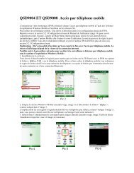
9.7 P.T.Z CONFIGURATIONClick the PTZ icon to configure the PTZ camera’s controlsMOBILE SURVEILLANCE CHAPTER 10This video surveillance card supports mobile surveillance on smart phones <strong>and</strong> other devicesrunning Android,Symbian <strong>and</strong> Windows Mobile Pro operating systems along with the iPad<strong>and</strong> iPhone on 3G networks. To access the card from these devices you must have firstconfigured your card for remote access as shown beginning with Section 9.2 ConfiguringRouter for Remote Access.10.1 WINDOWS MOBILE PROWindows Mobile Pro 6.1 <strong>and</strong> 6.5PROTOCOL SETUPProtocol - Communication protocol of P.T.ZdevicePort - Set the serial port numberAddress - The communication address ofP.T.Z device (ID number)PICTURE 9-64PICTURE 9-65STEP 1. Activate mobile network access on themobile phone.STEP 2. Run Internet ExplorerSTEP 3. Input the DVR’s IP address or DDNSdomainSTEP 4. You will be asked to download thesoftware PCam. Click on the software nameto open the download dialog pop-upSERIAL PORT SETUPYou should first enable the P.T.Z control function of selected camera <strong>and</strong> select a port numberin P.T.Z Protocol Setup <strong>and</strong> then set corresponding parameters. You should get the Baudrate, Protocol <strong>and</strong> Address from your PTZ camera or its manual before proceeding.PICTURE 10-1Port - Set the port numberBaud rate - Set the P.T.Z device Baud rate,default value is 9600, used value must matchBaud rate on PTZ control boardData bits - The default value is 8, used valuemuch match Baud rate on PTZ control board.Parity - Odd <strong>and</strong> even parity bit, default Null,used value must match Baud rate on PTZcontrol boardStop bits - Default value is 1, used value mustPICTURE 9-66match Baud rate on PTZ control boardNotice: Users should look into the P.T.Zdevice <strong>and</strong> get Baud rate, Protocol <strong>and</strong>Address first, <strong>and</strong> then set other valuesaccordingly.By clicking Copy To you can copy the setting of this channel to any other selected channel.STEP 5. Click Yes to start downloading <strong>and</strong>installing.PICTURE 10-2CHAPTER 10 MOBILE SURVEILLANCE78 79
OPERATING INSTRUCTIONS FORIPHONE/IPADSTEP 1. Launch SuperCam. This will bring upthe Login interface.Live View InterfaceYou can access the different viewing functions of the DVR in a similar manner to the controlson the DVR itself.STEP 2. Input the DVR’s IP address or DDNSdomain name, User Name <strong>and</strong> Password.Check the “Remember Server” box to savePICTURE 10-22this setting. The User Name <strong>and</strong> Passwordare the same as used on the DVR. Thedefault is SYSTEM with no password.If you are monitoring multiple devices,previously saved login data for these devicescan be accessed using the button onthe right.Main MenuThis window contains the function buttons needed to access <strong>and</strong> control your system.PICTURE 10-24 PICTURE 10-25Clicking on the help icon will list the functions aswell as how to use them. They are also definedbelow:PICTURE 10-23Button Function Button FunctionPlayback Playback recorded files Image Image viewLog Log record Server List Device listLive Live view Settings Software settingsInformation Device information view Help Software help centerLogoff Logoff <strong>and</strong> return to logininterfaceButton Function Button FunctionSwitch channelsSnap picturePICTURE 10-26 PICTURE 10-27Close the video of the currentchannelSwitch to single image viewMove the dome horizontally<strong>and</strong> vertically. The centersquare stops the movement.PresetSwitches to PTZ interfaceRecordSwitch to 4-image viewZoom In/Focus In/Iris OpenZoom Out/Focus Out/Iris CloseSelect the preset pointCHAPTER 10 MOBILE SURVEILLANCEGroup Set the cruise line Speed Rotate speed of the PTZH-Reverse Inverts PTZ control (up is down) V-Reverse Inverts PTZ control (left is right)86 87
Image View InterfaceButtonFunctionPrevious pictureNext pictureTo first pictureTo last pictureCopy pictures to albumDeletePICTURE 10-28Record Playback InterfaceClicking on a recorded file will start the playback. The controls at the bottom of the screenallow the user to move through the video.ButtonButtonFunctionPlayPauseStopReverseFast ForwardFunctionAdd a serverModify a server connectionPICTURE 10-29Server List InterfaceThis allows you to add, delete or modify the DVR connection or connections if you areremotely monitoring multiple systems.Configuration InterfaceThis window allows you to configure the main settings for how files are recorded <strong>and</strong> saved aswell as how alerts are h<strong>and</strong>led.Record file clip size – This is the maximum size ofa single video clip.Reserved disk space – This is the amount ofspace reserved for video recordings on the internalmemory. If the available disk space is less than thatselected, the video will stop.Display mode – Select between single or fourscreenlive displayRemember display order – The user can choosewhether the phone remembers the display order ornot.Alarm – If turned on, this will trigger an audiblealarm when a Video Loss, Sensor or Motion eventoccurs.Shake Alarm – If turned on, this will cause thedevice to vibrate when a Video Loss, Sensor orMotion event occurs.PICTURE 10-31Information View InterfaceThis presents information on the cell phone you are using the SuperCam software version onas well as the software itself.Device ID: This is the ID of the DVR you areconnected to.Software Version: The current connection devicesoftware versionBuild Date: The date the software was releasedSoftware Version: The current version of theSuperCam software in use on your phoneSoftware Build Date: The date this version ofSuperCam was releasedPICTURE 10-32CHAPTER 10 MOBILE SURVEILLANCEDelete a serverPICTURE 10-3088 89
10.4 ANDROIDSOFTWARE INSTALLATIONSTEP 1. Enter the Android MarketSTEP 2. Search for “SuperCam”STEP 5. You can view the download <strong>and</strong>installation process in Notifications. Oncedownload is complete, the software willinstall automatically.PICTURE 10-33STEP 3. Click the Install buttonOPERATING SUPERCAMLoginSTEP 1. Launch SuperCam. This will bring upthe Login interface.PICTURE 10-36PICTURE 10-34STEP 4. Click the OK button to confirm thedownloadSTEP 2. Input the DVR’s IP address or DDNSdomain name, User Name <strong>and</strong> Password.Check the “Remember Server” box to savethis setting. The User Name <strong>and</strong> Passwordare the same as used on the DVR. Thedefault is SYSTEM with no password.If you are monitoring multiple devices,previously saved login data for these devicescan be accessed using the button onthe right.PICTURE 10-37CHAPTER 10 MOBILE SURVEILLANCEPICTURE 10-35PICTURE 10-3890 91
Main MenuThis window contains the function buttons needed to access <strong>and</strong> control your system.Image ViewButton FunctionPrevious pictureNext pictureClicking on the help icon will list the functions aswell as how to use them. They are also definedbelow:Zoom inZoom outDeleteReturnPICTURE 10-40Button Function Button FunctionPlayback Playback recorded files Image Image viewPICTURE 10-39Record PlaybackClicking on a recorded file in the Recorded Filewindow will start the playback.Log Log record Server List Device listLive Live view Settings Software settingsInformation Device information view Help Software help centerLogoffLogoff <strong>and</strong> return to logininterfaceLive ViewIn this display you can access the different viewing functions of the DVR in a similar manner tothe controls on the DVR itself.Button Function Button FunctionSwitch channelsSnap pictureTalkFull ScreenMove the dome horizontally<strong>and</strong> vertically. The centersquare stops the movement.PresetSwitches to PTZ interfaceRecordReturnZoom In/Focus In/Iris OpenZoom Out/Focus Out/Iris CloseSelect the preset pointGroup Set the cruise line Speed Rotate speed of the PTZThe controls at the bottom of the screen allow theuser to move through the video.ButtonFunctionPlayPauseStopFull screenReturnPICTURE 10-41CHAPTER 10 MOBILE SURVEILLANCEPICTURE 10-4292 93
Server ListThis allows you to add, delete or modify the DVR connection or connections if you areremotely monitoring multiple systems.APPENDIXFREQUENTLY ASKED QUESTIONSInstallationCannot Install the SuperDVR DriverPossible causes:ButtonFunctionAdd a serverModify a server connectionDelete a serverReturn to Main Menu• H.264 series capture card has not been installed. Before installing driver, users shouldinstall capture card hardware in the PCI slot in the computer case before installing theSuperDVR program.• H.264 series capture card has not been installed correctly. Please unplug the card <strong>and</strong>install it again or change to another PCI slot, preferably next to the slot it was originallyinstalled in.• The card is not compatible with the PC system.PICTURE 10-43Information ViewThis presents information on the cell phone you are using the SuperCam software version onas well as the software itself.Device ID: This is the ID of the DVR you areconnected to.Software Version: The current connection devicesoftware versionBuild Date: The date the software was releasedSoftware Version: The current version of theSuperCam software in use on your phoneSoftware Build Date: The date this version ofSuperCam was releasedCan’t find H.264 Series Devices in Device ManagerEnter the Device Manager <strong>and</strong> cannot find corresponding H.264 series Devices, the possiblecause may be:• Windows system error. Restart computer.• Problem with H.264 series card. Replace the card.• Install SuperDVR to see if it finds card <strong>and</strong> installs the driver.OperationMeanings of the indicator lightsGrey- Normal stateRed - Sensor alarmYellow - Motion detection alarmBlue - Video lossLight Green - Manual record state Dark Green - Schedule record stateHow do the different record modes work?Users can set more than one record mode in Record setup (refer to Figure3-5), but actually,there is only one valid record mode for recording.The priority order of the recording modes is: Sensor Alarm Record > Motion Detection Record> Manual Record > Schedule RecordHow to set recycling record mode on the systemSelect ‘Recycle’ in basic configuration, refer to Figure4-1.PICTURE 10-44Users can select the percent of used disk space to set up “disk shortage alarm.” You caninput percent manually or choose the selectable options such as, 25%, 50%, <strong>and</strong> 75% toset up. For example, if selecting 50%, an alarm will warn you when your disk space usagereaches 50%.TIP It is recommended that you install SuperDVR onto the partition with yourWindows system (normally C:), <strong>and</strong> save recorded files on a different partition.APPENDIX94 95
How to set auto reboot functionWhen a Microsoft Windows system runs continuously for a couple of days the system maybecome unstable; therefore, it is suggested you restart the computer every few days.In the basic configuration, input Windows user name <strong>and</strong> password (It is not SuperDVR username <strong>and</strong> password), <strong>and</strong> select time interval, then the Windows system will automaticallyrestart according to the set time.If the Windows system shutdown unexpectedly, i.e. power supply is cut off, when computerreboots, SuperDVR system will automatically restart, <strong>and</strong> keep the settings you have entered.Users do not need to enable auto reboot function, but it’s suggested to inputTIP the Windows user name <strong>and</strong> password in the relative area, therefore when thesystem shuts down unexpectedly, users don’t need to input Windows <strong>and</strong>SuperDVR user names <strong>and</strong> passwords.How to quickly setup the schedule record functionPress ‘Shift’ or ‘Ctrl’ key, <strong>and</strong> draw the cursor in corresponding areas to make schedules formultiple channels.The frame rate seems to be lower than what I setThere is frame loss in image switch therefore the real recording frame rate is relatively lowerthan the theoretic value.Why can’t I select more channels to backup?Please draw the mouse in the channel selection area, or utilize Shift <strong>and</strong> Ctrl key for assistance.How to Use Network FunctionHow to monitor on the client-sideFirst enable ‘Web cameras service’ in basic configuration.Input the server Internet address in IE browser on the client-side, <strong>and</strong> the necessary <strong>web</strong>camdriver will be downloaded automatically, then users need to install the driver. After accessingthe <strong>web</strong>cam main interface, click ‘Login’ <strong>and</strong> input user name <strong>and</strong> password to log in thesystem.Why can’t I see the images?The possible causes:• The VGA card is too outdated or does not have enough Video RAM.• You need to install a newer version of DirectDraw.• SuperDVR cannot run on a version of Windows before Windows XP or on server versionsof Windows• Data port or comm<strong>and</strong> port is conflicting with other network services (please see section7.2)• The user is connected to Internet through LAN, <strong>and</strong> the network administrator has notenabled corresponding data port or comm<strong>and</strong> port.• The client-side has installed firewall software that may stop video transmission.• H.264 codec has not been installed properly, please download new version of Webcam(newer version of SuperDVR).• Slow network speed.What should I do if the Internet speed is quite slow?The more channels opened, <strong>and</strong> the slower the video transmission speed, therefore try to useone channel display mode when the network speed is slow.TIP There may be some surplus channels that have no video input. Switching offthe channels will help to improve transmission speed. (Refer to ‘4.1 BasicConfiguration’ about switching on/off channels.)Why can’t I start WebCam or Remote Playback programs?Possible causes:Other software is using these ports. If so, please change WebCam ports configuration or stopother software.Why can’t I download the WebCam software through Internet Explorer?The possible causes:• The client-side computer is not properly connected to Internet or LAN.• The server-end has not enabled ‘Web Camera Service’.• The default HTTP port is 80. It may be conflict with other Web servers, for example IIS. Ifso, please change to another port• Windows XP SP2 will block the OCX download. You should enable ‘Internet Option >Security Settings > Download unsigned ActiveX controls’.Why can’t the server be configured at the client-side?The possible causes:APPENDIX• It cannot be configured at the client-side, when the server is being configured at theserver-end.• Only the last configuration is valid if different configurations are deployed simultaneously.96 97
How much hard drive space do the recorded files take up?While the physical data capacity of a hard drive is fixed, how much video you can record uponit depends on your recording configurations. Higher quality recordings will take up more spaceon the drive <strong>and</strong> setting the DVR to record for more frequently will fill it up more rapidly.To determine the optimal capacity for your purposes, the chart below to estimate the size ofhard drive that you’ll need.VIDEOFORMATRESOLUTIONFRAMERATE(FPS)VIDEOQUALITYBITRATE(kbps)SPACEUSED(MB/h)NTSC CIF 30 Highest 1000k 465Higher 768k 297Medium 512k 230Low 384k 173Lower 256k 115Lowest 128k 56D1 7.5 Highest 500k 228Higher 375k 128Medium 250k 117Lower 192k 75Lowest 128k 61PAL CIF 25 Highest 1000k 466Higher 768k 295Medium 512k 235Low 384k 175Lower 256k 112Lowest 128k 56.4D1 7.5 Highest 500k 228Higher 375k 128Medium 250k 117Lower 192k 75Lowest 128k 61The formula for calculating the required disk space is:Total Recording Capacity = Used space per hour (MB/h) x Recording time (hour) xnumber of channelsExample: A customer is using the NTSC format (30 frames per second), CIF resolutionwith video quality set to Lowest <strong>and</strong> a total of 16 Channels. He wants the unit to recordcontinuously for a month. Therefore, the calculation will look like this:56(MB/h), x 24 (hours/day) x 30 (days) x 16 (channels) = 645,120MB or 650GBInstalling a 750GB SATA hard drive should provide enough space for one month’s continuousrecording time at those settings.Other QuestionsWhy doesn’t the computer display work, or why can’t I access Window system?The capture card may not be well installed. Unplug the card <strong>and</strong> try it again.IMPORTANT! Please unplug the power plug of the computer beforere-installing the card to avoid damaging the motherboard chip set.Why I can’t find the recorded files?You do not have enough hard drive space available for recording.Why is the screen’s display unstable with dithering <strong>and</strong> water-wave images?Possible causes:• Camera does not have enough power• There is external electromagnetic disturbance, or electrostatic disturbance on camera’sBNC connector. Use a shielded RG59 or RG6 cable.• You may need to update the driver for the video card on the system.• Problem with the video card. Try reinstalling the video card, or changing the video card.Why does it delay playing back, <strong>and</strong> why is it slow to close <strong>and</strong> open the driver?Possible causes:• Problem with the Windows system. Try rebooting the computer.• There are too many recorded files or too many fragments on the HDD, therefore it takestime to search for the files, you need delete the files that you don’t need, or need to rundisk defragmenter.• Capture card problem.• Computer hardware system is too outdated (processor too slow, not enough memory, ornot enough free space on hard drive).Why can’t I play back?Windows Media Player has been damaged, or decoder has not been installed properly. It issuggested you reinstall the player program or download a codec pack from K-litewww.free-codecs.com/download/K_lite_codec_pack.htm or www.divx.com.Computer problem, recorded files have been damaged. It is suggested to fix these files usingSuperAVIFix program.Why do I see some gray blocks on time progress bar area when playing back?Possible causes:• User has deleted these recorded files.• SuperDVR has deleted recorded file when recycling hard drive space.• Recorded files cannot be opened because the recording is on.Why could I see some old recording sections that weren’t available for play back?Possible causes:• You previously selected disk partitions different from the current partitions.• Database of recorded log was damaged.• You have installed SuperDVR on different directories.APPENDIX98 99
Precautions on changing system time• The SuperDVR system provides the retrieving mechanism for video files, which must takethe system time as a retrieving reference. To change the computer time after installationwill create a high risk of wrong time reference.• Before SuperDVR is used, it must be confirmed whether the current computer time iscorrect.• Deactivate computer auto time updating function of system.• Make sure the motherboard of the computer is in normal state.If system time must be changed, please do following preparations firstIf new time is later than current computer time (for example, change 2006/01/01 0:0:0(current system time) to 2007/01/01 0:0:0 (target time)), the change can be made directly.If new time is before the current computer time (for example, change 2007/01/01 0:0:0(current system time) to 2006/01/01 0:0:0 (target time)), first stop the video recording, backupall video data. Turn off SuperDVR, change computer time, <strong>and</strong> re-start SuperDVR.How to use REPAIRDB to repair SuperDVR databaseEnter the installation directory of SuperDVR.C:\ProgramFiles\SuperDVR\SuperDVR,open the REPAIRDB.EXE file. The user ID is ‘SYSTEM’,<strong>and</strong> no password is needed to enter. After entering, please select database to repair.How to set power options of Microsoft VISTA systemAfter installing VISTA system, you should enter the Start menu to choose ‘ControlPanel’. Select ‘System <strong>and</strong> Maintenance’ link. And select ‘Power’ option in ‘System <strong>and</strong>Maintenance’ window. Finally, Select the ‘High Performance Change Plan Setting’ option.QUICK START INSTRUCTIONSINSTALLATION INSTRUCTIONSSTEP 1. Insert the PCI card (But do not connect the Camera yet).STEP 2. Launch Windows.Windows will come up with Hardware wizard. Just click ‘Cancel’.STEP 3. Put the installation CD in the drive <strong>and</strong> open up SuperDVR folder <strong>and</strong> run the‘Setup’ file.Step 4. Follow the steps <strong>and</strong> in WinXP, it will come up with a message saying theprogram has not passed Windows logo testing, just select ‘Continue anyway’.STEP 5. Reboot computer once installation has completed.Once Booted up, On Desktop there will be a ‘SuperDVR’ icon.If this program recognizes the PCI card, program will open OK. Please log in to the program.Once your program is opened, now connect the Cameras.TROUBLESHOOTINGWhen opening the SuperDVR program, it says ‘ Can’t find card ’.Reboot one more time. If you still have the same problem, click ‘Start - Program - SuperDVR -Install’ <strong>and</strong> then uninstall the program. Reboot the computer. After reboot, go backto ‘Start - Program - SuperDVR - Install’. Now click on ‘Install’ to reinstall driver. ThenReboot.If for some reason still ‘Can’t find card ’, uninstall driver again. Shut down the computer. MovePCI Card to another slot. Reboot it. And click ‘Cancel’ when Windows detects it.Then reinstall driver by going to ‘Start - Program - SuperDVR - Install’.How to setup the <strong>web</strong> client to monitor from InternetOn Main Computer where DVR Card InstalledSTEP 1. Make sure the computer is connected to Internet. DSL or Cable Modem, or T1/T3 line.STEP 2. Find out your router’s public IP address. You can go to www.myipaddress fromthe computer the card is installed in.STEP 3. Open up the SuperDVR program <strong>and</strong> go to basic configuration. CheckmarkENABLE Web Camera Service <strong>and</strong> Remote Play Back Service.STEP 4. Make Note of Data Port, Comm<strong>and</strong> Port <strong>and</strong> RPB port.NOTE! If you are connecting to internet using a router, you need to configurethe setup of the router <strong>and</strong> do the port forwarding. Ports that need to beforwarded: 80, 1159 <strong>and</strong> 1160. Check your router manual on how to set thatup.APPENDIX100 101
On the Remote Client ComputerSTEP 1. Minimum Requirement for the client computer:- 2.8 GHZ processor or later-512 MB RAM- Windows 2000 (SP4 minimum), Win XP (SP2 minimum), Vista, Windows 7- MOST AGP <strong>and</strong> PCI-E cards with 128MB of Video RAM <strong>and</strong> full Direct Draw support aresupported.- DirectX 9.0 minimum- 500 GB free space on HDDSTEP 2. Open up Internet Explorer.If you are running XP with SP2 on Internet explorer, click ‘Tools - Internet Option - Security -Custom Level’, <strong>and</strong> enable ‘Download unsigned ActiveX controls’.STEP 3. In the IE textbox of the Internet explorer, input the router’s Public IP.STEP 4. Select ‘Live Surveillance’ <strong>and</strong> click ‘OK’ on displayed page.This will download the Webcam program. And then you can download Remote Playbackas well.STEP 5. On Desktop now you should see ‘WebCam’ <strong>and</strong> ‘Remote Playback’ icon.STEP 6. Open up Webcam, click ‘Key’ symbol icon.Username: system (Password blank unless you setup a password on the main computer).Server: this the IP address of the Main Computer.Data port: 1159 <strong>and</strong> Comm<strong>and</strong> port: 1160.STEP 7. Click ‘OK’. Now you should be able to view the live video from main computer.STEP 8. To play back the Video that has been recorded in Main Computer, Select‘Remote Playback’ on displayed page.STEP 9. Click on ‘Config’.Remote server: the IP address of main computer.IP port: 1161.STEP 10. Then click ‘OK’.STEP 11. Click ‘Login’. Now you should be able to play back the recorded video fromMain Computer.FUNCTION TREEAPPENDIX102 103
SYSTEM CONFIGURATION TREEIE CLIENT FUNCTION TREEConfigBasic ConfigVideo ProcAmpAlarm ConfigPTZ ConfigSchedule ConfigMotion Detect ConfigAuthorizationSystem ConfigCaption ModeInterval of AutoDwellCallMonitor ModeResolutionDeInterlaceStorage DiskSelect DiskRecycleWindows Auto LoginUserNamePasswordAuto RebootEnableIntervalTime SetLive AudioAudio ConfigSelect ChannelGain AdjustSelect CameraBrightnessContrastHueSaturationGain ModeAuto Gain EnabledGain ValueSystem ConfigBuzzerDisk ShortageMotion Hold TimeSensor Hold TimePrerecord EnablePrerecord TimeRemote AlarmEnablePC ListSensor Alarm ConfigOutput Device ConfigAutoMail ConfigSMTP ServerUser NameEmail FromPasswordSend ToSubjectMessage BodyAttach PictureSend Mail TestSerial PortPort IndexBaud rateData bitsParity bitsStop bitsProtocolSelect CameraEnableProtocol TypeAddressSelect Schedule TypeSchedule recordMotion DetectSensor AlarmAlarm OutputSchedule OperateSelect ScheduleAddEditDeleteSelect CameraMotion AreaSensitivityAdd UserEdit RightsDelete UserNetwork ServiceHttp PortWebCam ServiceEnableData PortComm<strong>and</strong> PortRPB ServiceEnableRPB PortVideo QualityCamera ConfigSwitchNameTime StampRecord ModeScheduleManualMotion DectectSensorRecord QualityRecord Frame RateScheduleManualMotion DectectSensorSecurityAPPENDIX104 105
QUESTIONS OR COMMENTS? CONTACT USPRODUCT SUPPORT, DOWNLOADS,FIRMWARE UPDATES & MANUALS24/7 Technical ResourcesLive Chat (M-F, 9-5 PST)www.Q-<strong>See</strong>.com/Support108 109
Digital Peripheral Solutions, Inc.8015 E. Crystal DriveAnaheim, CA 92807110