CASE STUDY - Keystone
CASE STUDY - Keystone
CASE STUDY - Keystone

Create successful ePaper yourself
Turn your PDF publications into a flip-book with our unique Google optimized e-Paper software.
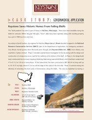
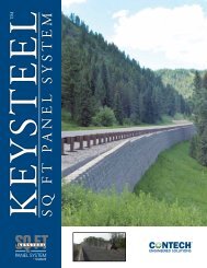
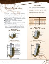
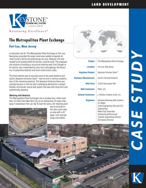
LAND DEVELOPMENTThe Metropolitan Plant ExchangeFort Lee, New JerseyA relocation site for The Metropolitan Plant Exchange in Fort Lee,New Jersey provided the larger-sized area needed to operate itsretail nursery, florist and greenhouse services. However, the landneeded to be leveled before the facility could be built. The proposedsite solution of building a structural retaining wall, first thought tobe routine, was complicated by area rock outcroppings, the discoveryof subsurface bedrock and local construction codes.The final solution was to excavate some of the area’s bedrock andbuild a <strong>Keystone</strong> Victorian Stone wall on and in vertical coordinationof the remaining bedrock. The <strong>Keystone</strong> Victorian Stone wasselected because it met the site’s challenging demand for a designflexible,structurally sound wall system that was both long-term andaesthetically-pleasing.Working with BedrockThe Metropolitan Plant Exchange’s site is located only a little morethan 10 miles from New York City, at an intersection of major highwaysin downtown Fort Lee, NJ. To level the land, a 36' retaining wallwas to be built onthe site’s south side,an area with a 45°slope, rock outcroppingsand relatedProject:Location:<strong>Keystone</strong> Product:<strong>Keystone</strong> Manufacturer:Wall Area:Wall Contractor:General Contractor:Engineers:The Metropolitan Plant ExchangeFort Lee, New Jersey<strong>Keystone</strong> Victorian StoneAnchor Concrete Products11,923 total square feetPillari, LLCJ. Fletcher Creamer & Son, Inc.<strong>Keystone</strong> Retaining Wall Systems,Inc.(Wall)Costa Engineering (Site and CivilEngineering)Melick-Tully Associates(Geotechnical/Structural)Creamer Engineering Services(Surveying Services)<strong>CASE</strong> <strong>STUDY</strong>
<strong>CASE</strong> <strong>STUDY</strong>subsurface bedrock. In some areas, the bedrock reached a height ofapproximately five feet above finished grade. The related subsurfacebedrock varied in its depth. Along with the site conditions, the projectwas further complicated by a construction code that restricted anyblasting to occur on the area. Also, all construction plans and buildinghad to be approved by the New Jersey Turnpike Authority and localmunicipal authorities.“Local codes did not allow for any blasting and hammering out all thebedrock would have used more time and equipment. It was cheaper tojust go over the bedrock, so you had to work with it,” said George Kreis,General Contractor, J. Fletcher Creamer & Son, Inc.LAND DEVELOPMENTwould continue driving in the rock dowels as we got to a certain elevation.Overall, the installation went well, it was just a coordinationeffort,” said Joseph Pillari, Wall Contractor, Pillari, LLC.The presence of bedrock in many sections of the wall’s reinforced zoneprevented some geogrid from being placed at its required length. Rockanchors were used in these areas. More than 200 rock anchors wereused at various elevations at the base of the wall. Some anchors wereplaced up to eight feet high on the wall. A five-inch diameter galvanizedschedule 40 steel spreader pipe was drilled and fastened to the rockanchors.Since excavation of all bedrock was not an option, the wall was to bereinforced with a combination of geogrid and drilled-in-place rockanchors. Extensive site surveying and soil testing established what portionof the bedrock was competent to hold the anchors. The testing alsoclassified some of the soils as SM or SP/SM soils and suitable for use asa controlled compacted fill for the retaining wall.The weaker bedrock was removed in a non-benched excavation bydrilling, splitting and hammering. The excavation of the establishednon-competent bedrock produced gaps along the wall’s base which werefilled with crushed stone. Excavation efforts also included establishingthe retaining wall’s leveling pad and drilling holes for rock dowel placement.After the dowels were placed, the concrete leveling was pouredand pinned to the bedrock and the first course of the wall was pinnedand grouted to the leveling pad.“It was a restricted space and we couldn’t work from the front at all.Also, both contractors had to work simultaneously in the same area. Atsome points, we would build the wall to a certain elevation and theyAccording to Jon Hansberger, Engineer, <strong>Keystone</strong> Retaining WallSystems, Inc., much of the remaining bedrock occurs at varying anglesthat produce additional forces exerted on the anchors and grid. Theadditional forces required extensive analysis that included a combinationof hand and design software calculations. Also engineered was alength extension for the wall. The <strong>Keystone</strong> Victorian Stone wall system’sflexibility allowed the wall to be extended to take advantage ofadditional parking space, however the extension required the executionof an acute angle. The engineered design solution combined the reinforcementgrid and lean concrete to accommodate the 60° angledcorner.The Metropolitan Plant Exchange presented unique design and installationchallenges requiring a flexible wall system. <strong>Keystone</strong> VictorianStone provided a long-term and aesthetically-pleasing solution thatproduced the maximum structural integrity while maintaining a reasonableproject cost.For more information on <strong>Keystone</strong> Victorian Stone or other innovative<strong>Keystone</strong> products, please visit www.keystonewalls.com or call800-747-8971. <strong>Keystone</strong> Retaining Wall Systems, Inc. is a subsidiary ofCONTECH Earth Stabilization Solutions (ESS) Inc.(www.contechess.com).©2007 <strong>Keystone</strong> Retaining Wall Systems, Inc. • A CONTECH Company4444 West 78th Street Minneapolis, Minnesota 55435 • 800.747.8971 • www.keystonewalls.com CS.0744