bascom-avr manual 1.11.7.4 - G. Heinrichs´ Homepage
bascom-avr manual 1.11.7.4 - G. Heinrichs´ Homepage
bascom-avr manual 1.11.7.4 - G. Heinrichs´ Homepage

You also want an ePaper? Increase the reach of your titles
YUMPU automatically turns print PDFs into web optimized ePapers that Google loves.
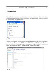
TIME TCPWRITE TCPWRITESTR TCPREADSWAP TAN TANH THIRDLINETOGGLE TRIM UCASE UPPERLINEUDPREAD UDPWRITE UDPWRITESTRVARPTR WAIT WAITKEY WAITMSWRITEWHILE-WEND WRITEEEPROM X10SEND X10DETECTInstallation of BASCOM -AVRWhen you downloaded the ZIP files from our website you need to UNZIP them all.The first file will unzip the file named SETUP.EXEThe second will unzip the file named SETUP.W02The third will unzip the file named SETUP.W03The fourth will unzip into SETUP.W04.The files can also come on diskettes. In that case there are no zip files and you can continuewithout unzipping.And finally the files can be on a CD-ROM. In that case the files are unzipped already too.International ResellersSupported ProgrammersAssembly MnemonicsMixing BASIC with assemblyIf you have questions, remarks or suggestions please let us know.You can contact us by sending an email to <strong>avr</strong>@mcselec.comOur website is located at http://www.mcselec.comFor info on updates : please read the readme.txt file that is installed into the BASCOM -AVRdirectoryThe commercial edition comes with a license file in the form of a dll. This file is always on the diskwhere the file SETUP.EXE is located. When explorer does not show this file, you must set theoption in explorer to view system files(because a DLL is a system file).Some resellers might distribute the DLL file in a zipped file. Or the file might have the extension of anumber like 123. In this case you must rename the number into DLL.Make sure the DLL is in the same directory as the SETUP.EXE file.When you are using the DEMO you don't need to worry about the license file.When you are installing on a NT machine like NT4 or W2000, you need to have Administratorrights.After installing BASCOM you need to run BASCOM once as an administrator too. After that youmay run BASCOM as any other user.Now run the SETUP.EXE by double clicking on it in explorer. Or from the DOS command prompt.MCS Electronics may update this documentation without notice.Products specification and usage may change accordingly.The following window will appear:(screen shots may differ a bit)MCS Electronics will not be liable for any mis-information or errors found in this document.All software provided with this product package is provided ' AS IS' without any warranty expressedor implied.MCS Electronics will not be liable for any damages, costs or loss of profits arising from the usage ofthis product package.No part of this document may be reproduced or transmitted in any form or by any means, electronicor mechanical, including photocopying and recording, for any purpose, without written permission ofMCS Electronics.Copyright MCS Electronics. All rights reserved.
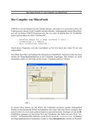
After reading the information, click the Next button.Now the following window appears:Click on the Next button to continue installation.The following license info window will appear:Fill in your name and company name.Click the Next button to continue.Now you have the change to select the directory in which BASCOM will be installed.Read the license agreement and click the Yes button when you agree.A window with additional information is then displayed. This information will be installed as areadme.txt file and contains information on how to get free updates. It also contains the passwordneeded to unzip updates.Select the Browse button to change the directory path if required.By default BASCOM-AVR will be installed into:
C:\Program Files\MCS Electronics\BASCOM-AVRAfter selecting the installation directory, click the Next button.This time you will be asked in which program group the BASCOM-AVR icon must be placed.By default, a new program group named MCS Electronics will be made.When the installation is completed you must click the Finish-button, and restart Windows.A sub directory named SAMPLES contains all the BASCOM-AVR sample files.A sub directory named LIB contains the Library files.After selecting the group, click the Next button to continue.A summary will be shown. You may go back and change your settings. Otherwise, click the Nextbutton to complete the installation of BASCOM-AVR.
File OpenWith this option you can load an existing program from disk.BASCOM saves files in standard ASCII format. Therefore, if you want to load a file that was madewith another editor be sure that it is saved as an ASCII file.Close the current program.File CloseWhen you have made changes to the program, you will be asked to save the program first.Note that you can specify that BASCOM must reformat the file when it opens it with the OptionsEnvironment option. This should only be necessary when loading files made with another editor.File close shortcut :File open shortcut :, CTRL+O
File SaveWith this option, you save your current program to disk under the same file name.If the program was created with the File New option, you will be asked to name the file first. Use theFile Save As option to give the file another name.Note that the file is saved as an ASCII file.File Save AsWith this option, you can save your current program to disk under a different file name.Note that the file is saved as an ASCII file.File save as shortcut :File save shortcut :, CTRL+S
File Print PreviewWith this option, you can preview the current program before it is printed.Note that the current program is the program that has the focus.File PrintWith this option, you can print the current program.Note that the current program is the program that has the focus.File print preview shortcut :File print shortcut :, CTRL+P
File ExitWith this option, you can leave BASCOM.If you have made changes to your program, you can save them upon leaving BASCOM.File exit shortcut :Edit UndoWith this option, you can undo the last text manipulation.Edit Undo shortcut : , CTRL+Z
With this option, you can redo the last undo.Edit RedoEdit CutWith this option, you can cut selected text into the clipboard.Edit Redo shortcut :, CTRL+SHIFT+ZEdit cut shortcut :, CTRL+X
Edit CopyWith this option, you can copy selected text into the clipboard.Edit PasteWith this option, you can paste text from the clipboard into the current cursor position.Edit copy shortcut :, CTRL+CEdit paste shortcut :, CTRL+V
Edit FindWith this option, you can search for text in your program.Text at the cursor position will be placed in the find dialog box.Edit Find shortcut : , CTRL+FEdit Find NextWith this option, you can search for the last specified search item.Edit Find Next shortcut : , F3
Edit ReplaceWith this option, you can replace text in your program.Edit GotoWith this option, you can immediately go to a line .Edit Replace shortcut :, CTRL+REdit go to line shortcut :,CTRL+G
Edit Toggle BookmarkWith this option, you can set/reset a bookmark, so you can jump in your code with the Edit Go toBookmark option. Shortcut : CTRL+K + x where x can be 1-8With this option, you can jump to a bookmark.Edit Goto BookmarkThere can be up to 8 bookmarks. Shortcut : CTRL+Q+ x where x can be 1-8
Edit Indent BlockWith this option, you can indent a selected block of text.With this option, you can un-indent a block.Edit Unindent BlockEdit Indent Block shortcut :, CTRL+SHIFT+IEdit Unindent Block shortcut :, CTRL+SHIFT+U
Program CompileWith this option, you can compile your current program.Your program will be saved automatically before being compiled.The following files will be created depending on the Option Compiler Settings.Program Syntax CheckWith this option, your program is checked for syntax errors. No file will be created except for anerror file, if an error is found.Program syntax check shortcut, CTRL + F7Filexxx.BINxxx.DBGxxx.OBJxxx.HEXxxx.ERRxxx.RPTxxx.EEPDescriptionBinary file which can be programmed into the microprocessorDebug file that is needed by the simulator.Object file for simulating using AVR Studio. Also needed by the internalsimulator.Intel hexadecimal file, which is needed by some programmers.Error file. Only created when errors are found.Report file.EEPROM image fileIf a serious error occurs, you will receive an error message in a dialog box and the compilation willend.All other errors will be displayed at the bottom above the status bar.When you click on the line with the error info, you will jump to the line that contains the error. Themargin will also display the sign.At the next compilation, the error window will disappear.Program compile shortcut:, F7
Program Show ResultUse this option to view the result of the compilation.See the Options Compiler Output for specifying which files must be created.The files that can be viewed are report and error._RAMSIZE : size of SRAM_ERAMSIZE : size of EEPROM_XTAL : value of crystal_BUILD : number that identifies the version of the compilerFile show result shortcut :,CTRL+WInformation provided in the report:InfoReportDate and timeCompilerProcessorSRAMEEPROMROMSIZEROMIMAGEBAUDXTALBAUD errorXRAMStack startS-StacksizeS-StackstartFramesizeFramestartLCD addressLCD RSLCD modeLCD DB7-DB4LCD ELCD RSVariableConstantDescriptionName of the programThe compilation date and time.The version of the compiler.The selected target processor.Size of microprocessor SRAM (internal RAM).Size of microprocessor EEPROM (internal EEPROM).Size of the microprocessor FLASH ROM.Size of the compiled program.Selected baud rate.Selected XTAL or frequency.The error percentage of the baud rate.Size of external RAM if available.The location in memory, where the hardware stack points to. The HW-stack pointergrows down.The size of the software stack.The location in memory where the software stack pointer points to. The softwarestack pointer grows down.The size of the frame. The frame is used for storing local variables.The location in memory where the frame starts.The address that must be placed on the bus to enable the LCD display E-line.The address that must be placed on the bus to enable the LCD RS-lineThe mode the LCD display is used with. 4 bit mode or 8 bit mode.The port pins used for controlling the LCD in pin mode.The port pin used to control the LCD enable line.The port pin used to control the LCD RS line.The variable name and address in memoryConstants name and valueSome internal constants are :_CHIP : number that identifies the selected chip
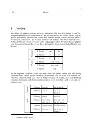
With this option, you can simulate your program.Program SimulateYou can simulate your programs with AVR Studio or any other Simulator available or you can usethe build in Simulator.Which one will be used when you press F2 depends on the selection you made in the OptionsSimulator TAB.Program Simulate shortcut :, F2To use the build in Simulator the files DBG and OBJ must be selected from the Options CompilerOutput TAB.The OBJ file is the same file that is used with the AVR Studio simulator.The DBG file contains info about variables and many other info needed to simulate a program.This is sthe STEP button. Pressing this button(or F8) will execute one code line of your BASICprogram. After the line is executed the simulator will be in the pause state.This is the STEP OVER button. It has the same effect as the STEP button but sub programsare executed and there is no step into the SUB program. You can also press SHIFT+F8This is the RUN TO button. The simulator will RUN to the current line. The line must containexecutable code.This button will show the register window.The values are show in hexadecimal format. To change a value click the cell of the Val column andtype the new value.This is the IO button and will show the IO registers.The Sim window is divided into a few sections:The ToolbarThe toolbar contains the buttons you can press to start an action.This starts a simulation. It is the RUN button. The simulation will pause when you press thepause button. You can also press F5.This is the pause button. Pressing this button will pause simulation.This is the STOP button. Pressing this button will stop simulation and you can't continue. Thisbecause all variables are reset. You need to press this button when you want to simulate yourprogram again.The IO window works the same like the Register window. Blank rows indicate that there is no IOregisterassigned to that address.( The blank rows might be deleted later.)Pressing this button shows the Memory window.
Changing the value of the variables works the same as for the Variable TAB.WATCHThe Watch-TAB can be used to enter an expression that will be evaluated during simulation. Whenthe expression is true the simulation is paused.Type the expression in the text-field and press the Add-button.When you press the Modify-button the current selected expression from the list is modified with thetyped value.To delete an expression you must select the expression from the list and press the Remove-button.When the expression becomes true the expression that matches will be selected and the Watch-TAB will be shown.The values can be changed the same way like in the Register window.When you move from cell to cell you can view in the status bar which variable is stored in theaddress.UPThe refresh variables button will refresh all variables during a run(F5). When you use the hardwaresimulator, the LEDS will only update their state when you have enabled this option. Note that usingthis option will slow down simulation.Under the toolbar section there is a TAB with the pages:VARIABLESThis TAB shows the status of the microprocessor SREG register.The flags can be changed by clicking their checkboxes.The software stack , hardware stack and frame pointer v alues are also shown. The minimum ormaximum value during simulation is shown. When one of the data is entering another one there is acase of stack/frame overflow.This will be signaled with a pause and a checkbox.You can add variables by double clicking in the Variable-column. A list will pop up from which youcan select the variable.To watch an array variable you can type the name of the variable with the index.During simulation you can change the values of the variables in the Value-column, Hex-column orBin-column. You must press ENTER to store the change.To delete a row you can press CTRL+DEL.To enter more variables, press the DOWN-key so a new row will become visible.It is also possible to select a variable by selecting it from the code window, and then pressing enter.The snapshot button will create a snapshot of the registers and HW registers.So it will create a copy of the memory once you press the snapshot button.You will notice that the snapshot button will change into ‘Stop’Now execute some code by pressing F8 and press the Snapshot button again.A window will pop up that will show all modified address locations.This can help at determining which registers a statement uses.When you write an ISR with the NOSAVE option you can determine the used registers and saveonly the modified registers.INTERRUPTSLOCALSThis TAB shows the interrupt sources. When no ISR's are programmed all buttons will be disabled.The LOCAL window show the variables in a SUB or FUNCTION. LOCAL variables are also shown.You can not add variables.By clicking a button the corresponding ISR is executed.
The pulse generator can be used to supply pulses to the timer when used in counter mode.Select the pin from the pull down box. Depending on the chip one or more pins are available. Mostchips have 2 counter so 2 input pins.Select the number of pulse and the delay time and press the Pulse-button to generate the pulses.The delay time is needed since other tasks must be processed as well.The option ‘Enable timers’ must be selected when you want to simulate timers/counters.The top section is a virtual LCD display. It works for display code in PIN mode and bus mode. Forbus mode only 8-bit bus mode is supported by the simulator.The LED bars below are a visual indication of the ports.By clicking a LED it will toggle.PA means PORTA, PB means PORTB etc.IA means PINA, IB means PINB etc.It depends on the kind of microprocessor you have selected, which ports will be shown.TERMINAL SectionUnder the TAB window you will find the terminal emulator window.When you use PRINT, the output will be shown in this window.When you use INPUT in your program, you must set the focus to the terminal window and type theneeded value.You can also print the values directly to the COM port.Check the Terminal option to enable this feature.The terminal emulator settings will be used for the baud rate and COM port.SOURCE SectionUnder the Terminal section you find the Source Window.It contains the program you simulate. All lines that contain executable code have a yellow point inthe left margin.You can set a breakpoint on these lines by pressing F9.By moving the mouse cursor over a variable name the value is shown in the status bar.When you select a variable and press ENTER it will be added to the Variable window.When you want to use the keys (F8 for stepping for example) the focus must be set to the SourceWindow.A blue arrow will show the line that will be executed next.The hardware simulator.By pressing the hardware simulation buttonthe windows shown below will be displayed.Right beside the PIN leds, there is a track bar. This bar can be used to simulate the input voltage ofthe ADC converter. Note that not all chips have an ADC converter. You can set a value for eachchannel.Beside the trackbar is a numeric keypad. This keypad can be used to simulate the GETKBD()function.When you simulate the getkbd() it is important that you press/click the keyboard button beforerunning the getkbd() line !!!With the Comparator simulator, you can specify the logic level on IN0.Enable Real Hardware SimulationBy clicking thebutton you can simulate the ports in circuit!In order to get it work you must compile the basmon.bas file.When compiled program a chip.Lets say you have the DT006 simmstick. And you are using a 2313 AVR chip.Open the basmon.bas file and change the line with $REGFILE = "xxx" into $REGFILE ="2313def.dat"Now compile the program. Program the chip. It is best to set the lock bits so the monitor does notget overwritten when you accidentally press F4.The real hardware simulation only works when the target micro system has a serial port. Most haveand so does the DT006.Connect a cable between the COM port of your PC and the DT006. You probably already have oneconnected. Normally it is used to send data to the terminal emulator with PRINT.The monitor program is compile with 19200 baud. The Options Communication settings must be setto the same baud rate!The same settings for the monitor program are used as for the Terminal emulator. So select theCOM port and the baud rate of 19200.Power up the DT006. It probably was since you created the basmon program and stored it in the2313.When you press the real hardware simulation button now the simulator will send and receive datawhen a port, pin or ddr register is changed.This allows you to simulate an attached LCD display for example. Or something simpler, the LED.In the SAMPLE dir you will find a program DT006. You can compile thie program and press F2.When you step through the program the LED's will change!All statements can be simulated this way but the have to be static. Which means that 1wire will notwork because it depends on timing. I2C has a static bus and that will work.It is important that when you finish your simulation sessions that you click the button again todisable the Real hardware simulation.
When the program hangs it probably means that something wend wrong in the communication. Theonly way to escape is to press the Real hardware simulation again.I think the simulation is a cost effective way to test attached hardware.Program Send to ChipThis option will bring up the selected programmer or will program the chip directly if this option isselected from the Programmer options.The refresh variables button will refresh all variables during a run(F5). When you use the hardwaresimulator, the LEDS will only update their state when you have enabled this option. Note that usingthis option will slow down simulation.Program send to chip shortcutMenu itemFile ExitFile, TestBuffer ClearBuffer Load from fileBuffer Save to fileChip IdentifyWrite buffer into chipRead chipcode intobufferChip blank checkChip eraseChip verifyChip Set lockbitsChip autoprogramRCEN, F4DescriptionReturn to editorWith this option you can set the logic level to the LPT pins. This is onlyintended for the Sample Electronics programmer.Clears bufferLoads a file into the bufferSaves the buffer content to a fileIdentifies the chipPrograms the buffer into the chip ROM or EEPROMReads the code or data from the chips code memory or data memoryChecks if the chip is blankErase the content of both the program memory and the data memoryVerifies if the buffer is the s ame as the chip program or data memoryWrites the selected lock bits LB1 and/or LB2. Only an erase will reset thelock bitsErases the chip and programs the chip. After the programming iscompleted, verification is performed.Writes a bit to enable the internal oscillator. This RCEN bit is only availableon some AVR chips.The following window will be shown:
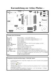
Note that a chip must be ERASED before it can be programmed.Tools Terminal EmulatorWith this option you can communicate via the RS-232 interface to the microcomputer. The followingwindow will appear:Information you type and information that the computer board sends are displayed in the samewindow.Note that you must use the same baud rate on both sides of the transmission. If you compiled yourprogram with the Compiler Settings at 4800 baud, you must also set the Communication Settings to4800 baud.The setting for the baud rate is also reported in the report file.File UploadUploads the current program in HEX format. This option is meant forloading the program into a monitor program.File EscapeAborts the upload to the monitor program.File ExitCloses terminal emulator.Terminal ClearClears the terminal window.Terminal Open LogOpen or closes a LOG file. When there is no LOG file selected you will be asked to enter or select afilename. All info that is printed to the terminal window is captured into the log file. The menucaption will change into 'Close Log' and when you choose this option the file will be closed.The terminal emulator has a strange bug that you can't select the menu options by using thekeyboard. This is an error in the terminal component and I hope the third party will fix this bug.
Tools LCD DesignerWith this option you can design special characters for LCD-displays.The following window will appear:With this option the following window will appear:Tools LIB ManagerThe LCD-matrix has 7x5 points. The bottom row is reserved for the cursor but can be used.You can select a point by clicking the left mouse button. If a cell was selected it will be deselected.Clicking the Set All button will set all points.Clicking the Clear All button will clear all points.When you are finished you can press the Ok button : a statement will be inserted in your activeprogram-editor window at the current cursor position. The statement looks like this :Deflcdchar ?,1,2,3,4,5,6,7,8You must replace the ?-sign with a character number ranging from 0-7.The Libraries are shown in the left pane. When you select one the routines that are in the library willbe shown in the right pane.By selecting a routine you can DELETE it.By clicking the ADD button you can add an ASM routine to the library.The COMPILE button will compile the lib into a LBX file. When an error occurs you will get an error.By watching the content of the generated lbx file you can determine the error.A compiled LBX file does not contain comment and a huge amount of mnemonics is compiled intoobject code. This object code is inserted at compile time of the main BASIC program. And thisresults in faster compilation.The DEMO version comes with the compiled MCS.LIB file and is named MCS.LBX. The ASMsource is included with the commercial edition.With the ability to create LBX files you can create add on packages for BASCOM and sell them.The LBX files could be distributed for free and the ASM source could be sold.Some examples :?? - MODBUS crc routine for the modbus slave program.?? - Glcd.lib contains the graphical LCD asm codeCommercial packages available from MCS:?? - I2CSLAVE library
?? - BCCARD for communication with www.basiccard.com chipcardsSee $LIB for writing your own librariesTools Graphic ConverterThe Graphic converter is intended to convert BMP files into BASCOM Graphic Files (BGF) that canbe used with Graphic LCD displays.The following dialog box will be shown :To load a picture click the Load button.The picture can be maximum128 pixels high and 240 pixels width.When the picture is larger it will be adjusted.You can use your favorite graphic tool to create the bitmaps and use the Graphic converter toconvert them into black and white images.When you click the Save-button the picture will be converted into black and white.Any non-white color will be converted into black.The resulting file will have the BGF extension.You can also paste a picture from the clipboard by clicking the Paste button.Press the Ok-button to return to the editor.The picture can be shown with the ShowPic statement or the ShowpicE statement.The BGF files are RLE encoded to save space.When you use your own drawing routine you can also save the pictures uncompressed by settingthe Uncompressed checkbox. The resulting BGF files can not be shown with the showpic orshowpicE statements anymore in that case!The BGF format is made up as following:?? - first byte is the height of the picture?? - second byte is the width of the picture
?? - for each row, all pixels are scanned from left to right in steps of 6 or 8 depending on the fontsize. The resulting byte in stored with RLE compressionRLE used is : byte value, AA(hex), repeats.So a sequence of 5, AA, 10 means that a byte with the value of 5 must be repeated 16 times (hexnotation used)Tools Stack AnalyzerThe Stack analyzer helps to determine the proper stack size.See $DBG for the proper usage of this option.
Tools Auto UpdateThe auto update feature allows you to update BASCOM automatic.Before choosing this option you must close all editor windows.The auto update window looks like :You must first fill in the setting by clicking the Setup TAB.The setup options are described below.To check if there is a newer version of BASCOM available press the Info button.You must have a connection to the internet in order to use this option.The program will check the file update.ver on the internet and will compare the files on your system.The compare is based on the file size. The files are compared with the zipped files in yourBASCOM directory. There fore it is important that once you have updated the system, you do notmove or delete the downloaded zip files.When the zip files are not in the BASCOM\ZIPS directory or the file size is different, the file will beadded to the white window. A checkbox is set to indicate that you need to download it.Once Auto update knows which files are needed you may click the checkbox to skip the file fordownloading.When ready press the Update button to start the update process.All selected files will be downloaded and after the last file is downloaded the application will end.The application mcsunzip.exe is started automatic and this application unzips the downloaded files.After the files are unzipped the mcsunzip.exe will start BASCOM again.The Setup tab looks like:ItemDescriptionHTTP Port This should be set to 80PasswordProxyserverProxyportPrivacy noticeThe password is the password that you can find in the BASCOM application dir in thereadme.txt file. Copy it from there and paste it with CTRL+V. The –s shown as part ofthe password should not be copied.This is the name or IP address of the proxy server. Home users typically don’t have aproxy server. Ask your administrator for the TCP address.This is the proxy port number. Set it to 0 when you don’t have a proxy server.The auto update process only checks the MCS electronics website for the update.ver file. And willdownload the needed zipped files. The application will not send any information from your PC toeither the MCS website or any other location.It is good practice to use a firewall so you can check all in and out going data from your applicationswhen you are connected to the Internet.When you do not have an internet connection on your BASCOM PC.Follow this procedure to get the update:??- Download the zip files <strong>manual</strong> from the website www.mcselec.com/download/<strong>avr</strong> orwww.mcselec.com/download/<strong>avr</strong>/beta??- Copy the zip files to the BASCOM PC in a subdirectory named ZIPS??- ZIPS must be a subdir in the BASCOM application directory??- Create a file with notepad in the BASCOM application folder named uzp.lst??- Add all the ZIP file names to this files and save and close the uzp.lst file??- Run BASCOM and select Tools, Auto Update??- Select the Password-TAB??- Enter the password. The password can be found in the readme.txt file that is located in theBASCOM application folder??- As an alternative for typing in the password, use copy(CTRL+C) & paste(CTRL+V) so youdo not make type errors??- Exit BASCOM and run the program named mcsunzip.exe
??- This program will unzip the zip files and will start BASCOM when readyTools Plugin ManagerThe Plugin Manager allows you to specify which Plug-ins needs to be loaded the next time you startBASCOM.Just select the plug ins you want to load/use by setting the checkbox.The plug ins will be loaded under the Tools Menu.You need to add a button to the toolbar by pressing the right mouse button while the mouse cursoris pointed to the toolbar.When you want to write your own plug ins, contact plugin@mcselec.com
Options CompilerWith this option, you can modify the compiler options.The following TAB pages are available:Options Compiler ChipOptions Compiler ChipOptions Compiler OutputOptions Compiler CommunicationOptions Compiler I2C , SPI, 1WIREOptions Compiler LCDThe following options are available:Options Compiler ChipItemChipXRAMHW StackSoft StackFrame sizeXRAM waitstateExternal AccessenableDescriptionSelects the target chip. Each chip has a corresponding x.DAT file withspecifications of the chip. Note that some DAT files are not available yet.Selects the size of the external RAM. KB means Kilo Bytes.For 32 KB you need a 62256 STATIC RAM chip.The amount of bytes available for the hard ware stack. When you use GOSUB orCALL, you are using 2 bytes of HW stack space.When you nest 2 GOSUB’s you are using 4 bytes (2*2). Most statements needHW stack too. An interrupt needs 32 by tes.Specifies the size of the software stack.Each local variable uses 2 bytes. Each variable that is passed to a sub programuses 2 bytes too. So when you have used 10 locals in a SUB and the SUBpasses 3 parameters, you need 13 * 2 = 26 bytes.Specifies the size of the frame.Each local is stored in a space that is named the frame space.When you have 2 local integers and a string with a length of 10, you need a framesize of (2*2) + 11 = 15 bytes.The internal conversion routines used when you use INPUT num,STR(),VAL() etc,also use the frame. They need a maximum of 16 bytes. So for this example 15+16= 31 would be a good value.Select to insert a wait state for the external RAM.Select this option to allow external access of the micro. The 8515 for example canuse port A and C to control a RAM chip.
DefaultPress or click this button to use the current Compiler Chip settings as default forall new projects.Options Compiler OutputOptions Compiler OutputItemBinary fileDebug fileHex fileReport fileError fileAVR Studio objectfileSize warningSwap wordsOptimize codeShow internalvariablesDescriptionSelect to generate a binary file. (xxx.bin)Select to generate a debug file (xxx.dbg)Select to generate an Intel HEX file (xxx.hex)Select to generate a report file (xxx.rpt)Select to generate an error file (xxx.err)Select to generate an AVR Studio object file (xxx.obj)Select to generate a warning when the code size exceeds the Flash ROMsize.This option will swap the bytes of the object code words. Useful for someprogrammers. Should be disabled for most programmers.Don’t use it with the internal supported programmers.This options does additional optimization of the generated code. Since it takesmore time it is an option.Internal variables are used. Most of them refer to a register. Like _TEMP1 =R24. This option shows these variables in the report.
Options Compiler CommunicationOptions Compiler I2C, SPI, 1WIREOptions Compiler CommunicationItemBaud rateFrequencyDescriptionSelects the baud rate for the serial statements. You can also type in a new baud rate.Select the frequency of the used crystal. You can also type in a new frequency.The settings for the internal hardware UART are:No parity8 data bits1 stop bitNote that these settings must match the settings of the terminal emulator. In the simulator theoutput is always shown correct since the baud rate is not taken in consideration during simulation.With real hardware when you print data at 9600 baud, the terminal emulator will show weirdcharacters when not set to the same baud rate, in this example, to 9600 baud.Options Compiler I2C, SPI, 1WIREItemSCL portSDA port1WIREClockMOSIMISOSSUse hardware SPIDescriptionSelect the port that serves as the SCL-line for the I2C related statements.Select the port that serves as the SDA-line for the I2C related statements.Select the port that serves as the 1WIRE-line for the 1Wire related statements.Select the port that serves as the clock-line for the SPI related statements.Select the port that serves as the MOSI-line for the SPI related statements.Select the port that serves as the MISO-line for the SPI related statements.Select the port that serves as the SS-line for the SPI related statements.Select to use built-in hardware for SPI, otherwise software emulation of SPI willbe used. The 2313 does not have internal HW SPI so can only be used withsoftware spi mode.
Options Compiler LCDOptions CommunicationWith this option, you can modify the communication settings for the terminal emulator.Options Compiler LCDItemLCD typeBus modeData modeLCD addressRS addressEnableRSDB7-DB4Make upper 3 bitshigh in LCddesignerDescriptionThe LCD display used.The LCD can be operated in BUS mode or in PIN mode. In PIN mode, the datalines of the LCD are connected to the processor pins. In BUS mode the datalines of the LCD are connected to the data lines of the BUS.Select 4 when you have only connect DB4-DB7. When the data mode is 'pin' ,you should select 4.Select the mode in which the LCD is operating. In PIN mode, individualprocessor pins can be used to drive the LCD. In BUS mode, the external databus is used to drive the LCD.In BUS mode you must specify which address will select the enable line of theLCD display. For the STK200, this is C000 = A14 + A15.In BUS mode you must specify which address will select the RS line of the LCDdisplay. For the STK200, this is 8000 = A15For PIN mode, you must select the processor pin that is connected to the enableline of the LCD display.For PIN mode, you must select the processor pin that is connected to the RS lineof the LCD display.For PIN mode, you must select the processor pins that are connected to theupper four data lines of the LCD display.Some displays require that for setting custom characters, the upper 3 bits mustbe 1. Should not be used by default.ItemComportBaud rateParityDescriptionThe communication port of your PC that you use for ther terminal emulator.The baud rate to use.Parity, default None.Data bits Number of data bits, default 8.Stop bits Number of stop bits, default 1.HandshakeEmulationFontBack colorThe handshake used, default is none.Emulation used, default BBS ANSI.Font type and color used by the emulator.Background color of the terminal emulator.Note that the baud rate of the terminal emulator and the baud rate setting of the compiler options,must be the same in order to work correctly.
Options EnvironmentOPTIONAuto IndentDon't change caseReformat BAS filesDESCRIPTIONWhen you press return, the cursor is set to the next line at the currentcolumn positionWhen set, the reformat won't change the case of the text.Default is that the text is reformatted so every word begins with upper case.Reformat files when loading them into the editor.This is only necessary when you are loading files that where created withanother editor. Normally you won't need to set this option.OPTIONBackground colorKeyword colorComment colorASM colorDESCRIPTIONThe background color of the editor window.The color of the reserved words. Default Navy.The keywords can be displayed in bold too.The color of comment. Default green.Comment can be shown in Italic too.Color to use for ASM statements. Default purple.Reformat codeReformat code when entered in the editor.HW registers colorThe color to use for the hardware registers/ports. Default maroon.Smart TABWhen set, a TAB will go to the column where text starts on the previous line.Editor fontClick on this label to select another font for the editor window.Syntax highlightingThis options highlights BASCOM statements in the editor.Show marginShows a margin on the right side of the editor.CommentThe position of the comment. Comment is positioned at the right of yoursource code.TAB-sizeNumber of spaces that are generated for a TAB.KeymappingChoose default, Classic, Brief or Epsilon.No reformat extensionFile extensions separated by a space that will not be reformatted whenloaded.Size of new editorwindowWhen a new editor window is created you can select how it will be made.Normal or Maximized (full window)
Options SimulatorWith this option you can modify the simulator settings.OPTIONUse integratedsimulatorRun simulator aftercompilationProgramParameterDESCRIPTIONSet this option to use BASCOM’s simulator. You can also use AVR Studio byclearing this option.Run the selected simulator after a successful compilation.The path with the program name of the simulator.The parameter to pass to the program. {FILE}.OBJ will supply the name of thecurrent program with the extension .OBJ to the simulator.OPTIONTooltipsShow toolbarSave File As … for newfiles.Program after CompileFile locationUse HTML HelpAuto backupDESCRIPTIONShow tool tips.Shows the toolbar with the shortcut icons.Will display a dialogbox so you can give new files a name when they mustbe saved. When you dont select this option the default name will be giveto the file (nonamex.bas). Where x is a number.This option will run the programmer after the program is compiled withsuccess.Double click to select a directory where your program files are stored. Bydefault Windows will use the My Documents path.HTML help is available for download and when your OS supports HTMLhelp, you can turn this option on.W98,W98SE,W98ME and W2000 support HTML Help.Check this option to make periodic backups. When checked you canspecify the backup time in minutes.
Options ProgrammerWith this option you can modify the programmer settings.Use HEXProgramParameterOtherSelect when a HEX file must be sent instead of the bin file.The program to execute. This is your programmer software.The optional parameter that the program might need.Use {FILE} to insert the binary filename(file.bin) and {EEPROM} to insert thefilename of the generated EEP file.When ‘Use Hex’ is checked the filename (file.hex) will be inserted for {FILE}. In allcases a binary file will be inserted for {EEPROM} with the extension .EEPOPTIONProgrammerPlay soundErase WarningAuto flashAuto verifyUpload code anddataDESCRIPTIONSelect one from the list.Name of a WAV file to be played when programming is finished.Press the ..-button to select the file.Set this option when you want a confirmation when the chip is erased.Some programmers support auto flash. Pressing F4 will program the chip withoutshowing the programmer window.Some programmers support verifying. The chip content will be verified afterprogramming.Set this option to program both the FLASH memory and the EEPROM memoryParallel printer port programmersLPT addressPort address of the LPT that is connected to the programmer.Serial port programmerCOM portSTK500 EXEThe com port the programmer is connected to.The path of stk500.exe. This is the full file location to the files stk500.exe thatcomes with the STK500.
Options MonitorWith this option you can modify the monitor settings.Options PrinterWith this option you can modify the printer settings.There are only settings to change the margins of the paper.OPTIONUpload speedMonitor prefixMonitor suffixMonitor delayPrefix delayDESCRIPTIONSelects the baud rate used for uploadingString that will be send to the monitor before the upload startsString that us sent to the monitor after the download is completed.Time in millions of seconds to wait after a line has been sent to the monitor.Time in millions of seconds to wait after a prefix has been sent to the monitor.OPTIONLeftRightTopBottomDESCRIPTIONThe left margin.The right margin.The top margin.The bottom margin.
Cascade all open editor windows.Window CascadeTile all open editor windows.Window Tile
Window Arrange IconsArrange the icons of the minimized editor windows.Minimize all open editor windows.Window Minimize All
Help AboutThis option shows an about box as showed below.Shows the BASCOM help file.Help IndexWhen you are in the editor window, the current word will be used as a keyword.Your serial number is shown in the about box.You will need this when you have questions about the product.The library version is also shown. In this case, it is 1.00.You can compare it with the one on our web site in case you need an update.Click on Ok to return to the editor.
Help on HelpShows help on how to use the Windows help system.Help CreditsI would like to thank the following people for their contributions to BASCOM:?? Dr.-Ing. Claus Kuehnel for his book 'AVR RISC' , that helped me a lot when I began to studythe AVR chips. Check his website at http://www.ckuehnel.ch?? Atmel, who gave permission to use the AVR picture in the start up screen. And for the greattech support. Check their website at http://www.atmel.com?? Brian Dickens, who did most of the Beta testing. He also checked the documentation ongrammar and spelling errors.?? Eddie McMullen, who provided me with source code for the new parallel printer port SPIprogrammer. Check his website with 8051 and AVR related hardware athttp://www.eedevl.com?? Jack Tidwell. I used his FP unit. It is the best one I found and it saved lots of work.?? Josef Franz Vögel. He wrote the complete trig FP library.
KeyLEFT ARROWRIGHT ARROWUP ARROWDOWN ARROWHOMEENDPAGE UPPAGE DOWNCTRL+LEFTCTRL+RIGHTCTRL+HOMECTRL+ENDCTRL+ YINSF1F2F3F4F5F7F8F9F10CTRL+F7CTRL+FCTRL+GBASCOM Editor KeysActionOne character to the leftOne character to the rightOne line upOne line downTo the beginning of a lineTo the end of a lineUp one windowDown one windowOne word to the leftOne word to the rightTo the start of the textTo the end of the textDelete current lineToggles insert/overstrike modeHelp (context sensitive)Run simulatorFind next textSend to chip (run flash programmer)RunCompile FileStepSet breakpointRun toSyntax CheckFind textGo to lineCTRL+Q+x Go to Bookmark. X can be 1-8CTRL+RCTRL+SCTRL+TCTRL+PCTRL+WCTRL+XCTRL+ZSHIFT+CTRL+ZCTRL+INSSHIFT+INSCTRL+SHIFT+JCTRL+SHIFT+USelect textReplace textSave FileTerminal emulatorCompiler OptionsShow result of compilationCut selected text to clipboardUndo last modificationRedo last undoCopy selected text to clipboardCopy text from clipboard to editorIndent BlockUnindent BlockHold the SHIFT key down and use the cursor keys to select text. or keep the leftmouse key pressed and tag the cursor over the text to select.CTRL+K+x Toggle bookmark. X can be 1-8CTRL+LCTRL+MCTRL+NCTRL+OCTRL+PLCD DesignerFile SimulationNew FileLoad FilePrint File
Developing OrderStart BASCOM;Open a file or create a new one;Check the chip settings, baud rate and frequency settings for the target system;Save the file;Com pile the file;If an error occurs fix it and recompile (F7);Run the simulator;Program the chip(F4);Font EditorThe Font Editor is a Plugin that is intended to create Fonts that can be used with the SED Graphicaldisplay.When you have installed the Font Editor , a menu opion becomes available under the Tools menu :Font Editor.When you choose this option the following window will appear:You can open an existing Font file, or Save a modified file.The font files are installed into the Samples directorie.You can copy an image form the clipboard and you can move the image up , down, left and right.When you select a new character, the current character is saved. The suggest option will draw animage of the current selected character.When you keep the left mouse button pressed, you can set the pixels in the grid. When you keepthe right mouse button pressed, you can clear the pixels in the grid.When you choose the option to create a new Font, you can provide the name of the font, the heightof the font in pixels and thw width of the font in pixels.The Max ASCII is the last ASCII character value you want to use. Each character will occupyspace. So it is important that you do not choose a value that is too high and will not be used.
When you display normal text, the maximum number is 127 so it does not make sense to specify avalue of 255.PinOutThis plugin is based on the PinOut Viewer from Karl Jan Skontorp.You can download the Karl Jan’s program from www.mcselec.com/download/appnotes/<strong>avr</strong>-pins.zipThis program contains all the pictures from the AVR chips.The PinOut Plugin uses the same pictures , or you can add your own pictures.When the plugin is selected it will show asmall window :After you have choosen a picture from the list it will be displayed.
Additional HardwareOf course just running a program on the chip is not enough. You will probably attach all kind ofelectronics to the processor ports.BASCOM supports a lot of hardware and so has lots of hardware related statements.Before explaining about programming the additional hardware, it might be better to talk about thechip.The AVR internal hardwareAttaching an LCD displayUsing the I2C protocolUsing the 1WIRE protocolUsing the SPI protocolAVR Internal HardwareThe AVR chips all have internal hardware that can be used.For the description we have used the 8515 so some described hardware will not be available whenyou select a 2313 for example.Timer / CountersThe AT90S8515 provides two general purpose Timer/Counters - one 8-bit T/C and one 16-bit T/C.The Timer/Counters have individual pre-scaling selection from the same 10-bit pre-scaling timer.Both Timer/Counters can either be used as a timer with an internal clock time base or as a counterwith an external pin connection which triggers the counting.You can attach additional hardware to the ports of the microprocessor.The following statements will become available:I2CSEND and I2CRECEIVE and other I2C related statements.CLS, LCD, DISPLAY and other related LCD-statements.1WRESET , 1WWRITE and 1WREADMore about TIMEROMore about TIMER1The WATCHDOG Timer.Almost all AVR chips have the ports B and D. The 40 pin devices also have ports A and C that alsocan be used for addressing an external RAM chip. Since all ports are identical but the PORT B andPORT D have alternative functions, only these ports are described.PORT B
PORT DAVR Internal RegistersYou can manipulate the register values directly from BASIC. They are also reserved words. Theinternal registers for the AVR90S8515 are :Addr.Register$3F SREG I T H S V N Z C$3E SPH SP15 SP14 SP13 SP12 SP11 SP10 SP9 SP8$3D SPL SP7 SP6 SP5 SP4 SP3 SP2 SP1 SP0$3C Reserved$3B GIMSK INT1 INT0 - - - - - -$3A GIFR INTF1 INTF0$39 TIMSK TOIE1 OCIE1A OCIE1B - TICIE1 - TOIE0 -$38 TIFR TOV1 OCF1A OCF1B -ICF1 -TOV0-$37 Reserved$36 Reserved$35 MCUCR SRE SRW SE SM ISC11 ISC10 ISC01 ISC00$34 Reserved$33 TCCR0 - - - - - CS02 CS01 CS00$32 TCN T0 Timer/Counter0 (8 Bit)$31 Reserved$30 Reserved$2F TCCR1A COM1A1 COM1A0 COM1B1 COM1B0 - -PWM11 PWM10$2E TCCR1B ICNC1 ICES1 - - CTC1 CS12 CS11 CS10$2D TCNT1H Timer/Counter1 - Counter Register High Byte$2C TCNT1L Timer/Counter1 - Counter R egister Low Byte$2B OCR1AH Timer/Counter1 - Output Compare Register A High Byte$2A OCR1AL Timer/Counter1 - Output Compare Register A Low Byte$29 OCR1BH Timer/Counter1 - Output Compare Register B High Byte$28 OCR1BL Timer/Counter1 - Output Compare Register B Low Byte$27 Reserved$26 Reserved$25 ICR1H Timer/Counter1 - Input Capture Register High Byte$24 ICR1L Timer/Counter1 - Input Capture Register Low Byte$23 Reserved
$22 Reserved$21 WDTCR - - - WDTOE WDE WDP2 WDP1 WDP0$20 Reserved$1F Reserved - - - - - - - EEAR8$1E EEARL EEPROM Address Register Low BytePORTB = 40 will place a value of 40 into port B.Note that internal registers are reserved words. This means that they can't be dimensioned asBASCOM variables!So you can't use the statement DIM SREG As Byte because SREG is an internal register.You can however manipulate the register with the SREG = value statement.$1D EEDR EEPROM Data Register$1C EECR - - - - - EEMWE EEWE EERE$1B PORTA PORTA7 PORTA6 PORTA5 PORTA4 PORTA3 PORTA2 PORTA1PORTA0$1A DDRA DDA7 DDA6 DDA5 DDA4 DDA3 DDA2 DDA1 DDA0$19 PINA PINA7 PINA6 PINA5 PINA4 PINA3 PINA2 PINA1 PINA0$18 PORTB PORTB7 PORTB6 PORTB5 PORTB4 PORTB3 PORTB2 PORTB1PORTB0$17 DDRB DDB7 DDB6 DDB5 DDB4 DDB3 DDB2 DDB1 DDB0$16 PINB PINB7 PINB6 PINB5 PINB4 PINB3 PINB2 PINB1 PINB0$15 PORTC PORTC7 PORTC6 PORTC5 PORTC4 PORTC3 PORTC2 PORTC1PORTC0$14 DDRC DDC7 DDC6 DDC5 DDC4 DDC3 DDC2 DDC1 DDC0$13 PINC PINC7 PINC6 PINC5 PINC4 PINC3 PINC2 PINC1 PINC0$12 PORTD PORTD7 PORTD6 PORTD5 PORTD4 PORTD3 PORTD2 PORTD1PORTD0$11 DDRD DDD7 DDD6 DDD5 DDD4 DDD3 DDD2 DDD1 DDD0$10 PIND PIND7 PIND6 PIND5 PIND4 PIND3 PIND2 PIND1 PIND0$0F SPDR SPI Data Register$0E SPSR SPIF WCOL - - - - - -$0D SPCR SPIE SPE DORD MSTR CPOL CPHA SPR1 SPR0$0C UDR UART I/O Data Register$0B USR RXC TXC UDRE FE OR - - -$0A UCR RXCIE TXCIE UDRIE RXEN TXEN CHR9 RXB8 TXB8$09 UBRR UART Baud Rate Register$08 ACSR ACD - ACO ACI ACIE ACIC ACIS1 ACIS0$00 ReservedThe registers and their addresses are defined in the xxx.DAT files which are placed in theBASCOM-AVR application directory.The registers can be used as normal byte variables.
The 8-Bit Timer/Counter0AVR Internal Hardware TIMER0AVR Internal Hardware TIMER1The 16-Bit Timer/Counter1 (8515 other timers may be different)The 8-bit Timer/Counter0 can select its clock source from CK, pre-scaled CK, or an external pin. Inaddition it can be stopped.The overflow status flag is found in the Timer/Counter Interrupt Flag Register - TIFR. Controlsignals are found in the Timer/Counter0 Control Register - TCCR0. The interrupt enable/disablesettings for Timer/Counter0 are found in the Timer/Counter Interrupt Mask Register - TIMSK.When Timer/Counter0 is externally clocked, the external signal is synchronized with the oscillatorfrequency of the CPU. To assure proper sampling of the external clock, the minimum time betweentwo external clock transitions must be at least one internal CPU clock period. The external clocksignal is sampled on the rising edge of the internal CPU clock.The 16-bit Timer/Counter1 can select clock source from CK, pre-scaled CK, or an external pin. Inaddition it can be stopped.The different status flags (overflow, compare match and capture event) and control signals arefound in the Timer/Counter1 Control Registers - TCCR1A and TCCR1B.The interrupt enable/disable settings for Timer/Counter1 are found in the Timer/Counter InterruptMask Register - TIMSK.When Timer/Counter1 is externally clocked, the external signal is synchronized with the oscillatorfrequency of the CPU. To assure proper sampling of the external clock, the minimum time betweentwo external clock transitions must be at least one internal CPU clock period.The external clock signal is sampled on the rising edge of the internal CPU clock.The 16-bit Timer/Counter1 features both a high resolution and a high accuracy usage with the lowerprescaling opportunities.Similarly, the high prescaling opportunities make the Timer/Counter1 useful for lower speedfunctions or exact timing functions with infrequent actions.The Timer/Counter1 supports two Output Compare functions using the Output Compare Register 1A and B -OCR1A and OCR1B as the data sources to be compared to the Timer/Counter1 contents.The Output Compare functions include optional clearing of the counter on compareA match, andactions on the Output Compare pins on both compare matches.Timer/Counter1 can also be used as a 8, 9 or 10-bit Pulse With Modulator. In this mode the counterand the OCR1A/OCR1B registers serve as a dual glitch-free stand-alone PWM with centeredpulses.The Input Capture function of Timer/Counter1 provides a capture of the Timer/Counter1 contents tothe Input Capture Register - ICR1, triggered by an external event on the Input Capture Pin - ICP.The actual capture event settings are defined by the Timer/Counter1 Control Register -TCCR1B.In addition, the Analog Comparator can be set to trigger the Input Capture.The 8-bit Timer/Counter0 features both a high resolution and a high accuracy usage with the lowerpre-scaling opportunities. Similarly, the high pre-scaling opportunities make the Timer/Counter0useful for lower speed functions or exact timing functions with infrequent actions.
The Watchdog TimerAVR Internal Hardware Watchdog timerThe Watchdog Timer is clocked from a separate on-chip oscillator which runs at 1MHz. This is thetypical value at VCC = 5V.By controlling the Watchdog Timer pre-scaler, the Watchdog reset interval can be adjusted from16K to 2,048K cycles (nominally 16 - 2048 ms). The RESET WATCHDOG - instruction resets theWatchdog Timer.Eight different clock cycle periods can be selected to determine the reset period.If the reset period expires without another Watchdog reset, the AT90Sxxxx resets and executesfrom the reset vector.
Port BAVR Internal Hardware Port B1 1 Output No Push-Pull One OutputPort B is an 8-bit bi-directional I/O port. Three data memory address locations are allocated for thePort B, one each for the Data Register - PORTB, $18($38), Data Direction Register - DDRB,$17($37) and the Port B Input Pins - PINB, $16($36). The Port B Input Pins address is read only,while the Data Register and the Data Direction Register are read/write.All port pins have individually selectable pull-up resistors. The Port B output buffers can sink 20mAand thus drive LED displays directly. When pins PB0 to PB7 are used as inputs and are externallypulled low, they will source current if the internal pull-up resistors are activated.The Port B pins with alternate functions are shown in the following table:When the pins are used for the alternate function the DDRB and PORTB register has to be setaccording to the alternate function description.Port B Pins Alternate FunctionsPort Pin Alternate FunctionsPORTB.0 T0 (Timer/Counter 0 external counter input)PORTB.1 T1 (Timer/Counter 1 external counter input)PORTB.2 AIN0 (Analog comparator positive input)PORTB.3 AIN1 (Analog comparator negative input)PORTB.4 SS (SPI Slave Select input)PORTB.5 MOSI (SPI Bus Master Output/Slave Input)PORTB.6 MISO (SPI Bus Master Input/Slave Output)PORTB.7 SCK (SPI Bus Serial Clock)The Port B Input Pins address - PINB - is not a register, and this address enables access to thephysical value on each Port B pin. When reading PORTB, the PORTB Data Latch is read, andwhen reading PINB, the logical values present on the pins are read.PortB As General Digital I/OAll 8 bits in port B are equal when used as digital I/O pins. PORTB.X, General I/O pin: The DDBn bitin the DDRB register selects the direction of this pin, if DDBn is set (one), PBn is configured as anoutput pin. If DDBn is cleared (zero), PBn is configured as an input pin. If PORTBn is set (one)when the pin configured as an input pin, the MOS pull up resistor is activated.To switch the pull up resistor off, the PORTBn has to be cleared (zero) or the pin has to beconfigured as an output pin.DDBn Effects on Port B PinsDDBn PORTBn I/O PullupComment0 0 Input No Tri-state (Hi-Z)0 1 Input Yes PBn will source current if ext. pulled low.1 0 Output No Push-Pull Zero Output
Port DPort D Pins Alternate FunctionsAVR Internal Hardware Port DThe UCR register will by default not set bits 3 and 4 that enable the TXD and RXD pins for RS-232communication. It is however reported that this not works for all chips. In this case you must clearthe bits in the UCR register with the following statements:RESET UCR.3RESET UCR.4Port Pin Alternate FunctionPORTD.0 RDX (UART Input line )PORTD.1 TDX (UART Output line)PORTD.2 INT0 (External interrupt 0 input)PORTD.3 INT1 (External interrupt 1 input)PORTD.5 OC1A (Timer/Counter1 Output compareA match output)PORTD.6 WR (Write strobe to external memory)PORTD.7 RD (Read strobe to external memory)RD - PORTD, Bit 7RD is the external data memory read control strobe.WR - PORTD, Bit 6WR is the external data memory write control strobe.OC1- PORTD, Bit 5Output compare match output: The PD5 pin can serve as an external output when theTimer/Counter1 com-pare matches.The PD5 pin has to be configured as an out-put (DDD5 set (one)) to serve this f unction. See theTimer/Counter1 description for further details, and how to enable the output. The OC1 pin is alsothe output pin for the PWM mode timer function.INT1 - PORTD, Bit 3External Interrupt source 1: The PD3 pin can serve as an external interrupt source to the MCU. Seethe interrupt description for further details, and how to enable the sourceINT0 - PORTD, Bit 2INT0, External Interrupt source 0: The PD2 pin can serve as an external interrupt source to theMCU. See the interrupt description for further details, and how to enable the source.TXD - PORTD, Bit 1Transmit Data (Data output pin for the UART). When the UART transmitter is enabled, this pin isconfigured as an output regardless of the value of DDRD1.RXD - PORTD, Bit 0Receive Data (Data input pin for the UART). When the UART receiver is enabled this pin isconfigured as an output regardless of the value of DDRD0. When the UART forces this pin to be aninput, a logical one in PORTD0 will turn on the internal pull-up.When pins TXD and RXD are not used for RS-232 they can be used as an input or output pin.No PRINT, INPUT or other RS-232 statement may be used in that case.
Adding XRAMSome AVR chips like the 8515 for example can be extended with external RAM memory.On these chips Port A serves as a Multiplexed Address/Data input/output.Port C also serves as Address output when using external SRAM.The maximum size of a XRAM chip can be 64Kbytes.The STK200 has a 62256 ram chip (32K x 8 bit).Here is some info from the BASCOM userlist :If you do go with the external ram , be careful of the clock speed.Using a 4Mhz crystal , will require a SRAM with 70nS access timeor better. Also the data latch (74HC573) will have to be from a fasterfamily such as a 74FHC573 if you go beyond 4Mhz.You can also program an extra wait state, which slow it down a bit.Here you find a pdf file showing STK200 schematics:http://www.<strong>avr</strong> -forum.com/Stk200_schematic.pdfIf you use 32kRAM, then connect the /CS signal to A15 which giveto the range of &H0000 to &H7FFF, if you use a 64kRAM, thentie /CS to GND, so the RAM is selected all the time.Thanks to Colin O'Flynn for creating this circuit :
Attaching an LCD DisplayA LCD display can be connected with two methods.? ???By wiring the LCD -pins to the processor port pins.This is the pin mode. The advantage is that you can choose the pins and that they don't have tobe on the same port. This can make your PCB design simple. The disadvantage is that morecode is needed.? ???By attaching the LCD-data pins to the data bus. This is convenient when you have an externalRAM chip and will adds little code.The LCD-display can be connected in PIN mode as follows:Memory usageEvery variable uses memory. This memory is also called SRAM.The available memory depends on the chip.A special kind of memory are the registers in the AVR. Registers 0-31 have addresses 0-31.Almost all registers are used by the compiler or might be used in the future.Which registers are used depends on the statements you used.This brings us back to the SRAM.No SRAM is used by the compiler other than the space needed for the software stack and frame.Some statements might use some SRAM. When this is the case it is mentioned in the help topic ofthat statement.LCD DISPLAY PORT PINDB7 PORTB.7 14DB6 PORTB.6 13DB5 PORTB.5 12DB4 PORTB.4 11E PORTB.3 6RS PORTB.2 4RW Ground 5Vss Ground 1Vdd +5 Volt 2Vo 0-5 Volt 3Each 8 used bits occupy one byte.Each byte occupies one byte.Each integer/word occupies two bytes.Each Long or Single occupies four bytes.Each String occupies at least 2 byes.A string with a length of 10. occupies 11 byes. The extra byte is needed to indicate the end of thestring.Use bits or bytes where you can to save memory. (not allowed for negative values)The software stack is used to store the addresses of LOCAL variables and for variables that arepassed to SUB routines.Each LOCAL variable and passed variable to a SUB, uses two bytes to store the address. So whenyou have a SUB routine in your program that passes 10 variables, you need 10 * 2 = 20 bytes.When you use 2 LOCAL variables in the SUB program that receives the 10 variables, you needadditional 2 * 2 = 4 bytes.This leaves PORTB.1 and PORTB.0 and PORTD for other purposes.You can change these settings from the Options LCD menu.BASCOM supports many statements to control the LCD-display.For those who want to have more control the example below shows how to use the internalroutines.$ASMLdi _temp1, 5 'load register R24 with valueRcall _Lcd_control 'it is a control value to control the displayLdi _temp1,65 'load register with new value (letter A)Rcall _Write_lcd 'write it to the LCD-display$END ASMNote that _lcd_control and _write_lcd are assembler subroutines which can be called fromBASCOM.See the manufacturer's details from your LCD display for the correct assignment.The software stack size can be calculated by taking the maximum number of parameters in a SUBroutine, adding the number of LOCAL variables and multiplying the result by 2. To be safe, add 4more bytes for internally used LOCAL variables.LOCAL variables are stored in a place that is named the frame.When you have a LOCAL STRING with a size of 40 bytes, and a LOCAL LONG, you need 41 + 4bytes = 45 bytes of frame space.When you use conversion routines such as STR(), VAL() etc. that convert from numeric to stringand vice versa, you also need a frame. It should be 16 bytes in that case.Add additional space for the local data.Note that the use of the INPUT statement with a numeric variable, or the use of the PRINT/LCDstatement with a numeric variable, will also force you to reserve 16 bytes of frame space. Thisbecause these routines use the internal numericstring conversion routines.XRAMYou can easy add external memory to an 8515. Then XRAM will become available.(extendedmemory).
When you add a 32KB RAM, the first address wil be 0.But because the XRAM can only start after the SRAM, which is &H 0260, the lower memorylocations of the XRAM will not be used.Using the I2C protocolThe I2C protocol is a 2-wire protocol designed by Philips. Of course you also need power andground so it really needs 4 wires.ERAMMost AVR chips have internal EEPROM on board.This EEPROM can be used to store and retrieve data.In BASCOM, this data space is called ERAM.An important difference is that an ERAM variable can be written for a maximum of 100.000 times.So only assign an ERAM variable when it is needed and not in a loop.Constant code usageConstants are stored in a constant table.Each used constant in your program will end up in the constant table.The I2C protocol was invented for making designs of TV PCB's more simple. But with theavailability of many I2C chips, it is ideal for the hobbyist too.The PCF8574 is a nice chip - it is an I/O extender with 8 pins that you can use either as input oroutput.The design below shows how to implement an I2C-bus. The circuit shown is for the 8051 micro theAT89C2051 which is pin compatible with the AT90S2313. It also works for the AVR.R1 and R2 are 330 ohm resistors.R3 and R4 are 10 kilo-ohm resistors. For 5V, 4K7 is a good value in combination with AVR chips.For example:Print "ABCD"Print "ABCD"You can select which port pins you want to use for the I2C interface with the compiler settings.This example will only store one constant (ABCD).Print "ABCD"Print "ABC"In this example, two constants will be stored because the strings differ.The following information was submitted by Detlef Queck."Many people have over and over problems width I2C(TWI) Termination, use 4,7k or 10 k pullup?How long can the SCL,SDA Line width used pullup's go etc.etc.You can bring this incredible situation's down. Here is a Schematic for an active Termination of I2Cand TWI. We have this Schematic used for over 10 years, and have no problem's with it. The I2C(TWI) Line's can be up to 80cm(400KHz) without any problem when the Terminator is at the end ofthe Lines."
Using the 1 WIRE protocolThe 1 wire protocol was invented by Dallas Semiconductors and needs only 1 wire for thecommunication. You also need power and ground of course.This topic is written by Göte Haluza. He tested the new 1wire search routines and is building aweather station. Thanks!Dallas Semiconductor (DS) 1wire. This is a brief description of DS 1wirebus when used incombination with BASCOM. For more detailed explanations about the 1w-bus, please go tohttp://www.dalsemi.com. Using BASCOM, makes the world a lot easier. This paper will approachthe subject from a "BASCOM-user-point-of-view".1wire-net is a serial communication protocol, used by DS devices. The bus could be implemented intwo basic ways :With 2 wires, then DQ and ground is used on the device. Power is supplied on the DQ line, whichis +5V, and used to charge a capacitor in the DS device. This power is used by the device for itsinternal needs during communication, which makes DQ go low for periods of time. This bus is calledthe 1wirebus.With 3 wires, when +5V is supplied to the VDD line of the device, and DQ + ground as above. Thisbus is called the 2wirebus.So, the ground line is "not counted" by DS. But hereafter we use DS naming conventions.How it works. (1wire)The normal state of the bus is DQ=high. Through DQ the device gets its power, and performs thetasks it is designed for.When the host (your micro controller (uC)) wants something to happen with the 1w-bus, it issues areset-command. That is a very simple electric function that happens then; the DQ goes active lowfor a time (480uS on original DS 1w-bus). This put the DS-devices in reset mode; then (they) senda presence pulse, and then (they) listen to the host.The presence pulse is simply an active low, this time issued by the device(s).Now, the host cannot know what is on the bus, it is only aware of that at least 1 DS device isattached on the bus.All communication on the 1w-bus is initialized by the host, and issued by time-slots of active-low ona normally high line (DQ), issued by the device, which is sending at the moment. The devices(s)internal capacitor supplies its power needs during the low-time.How you work with 1w-busThereafter, you can read a device, and write to it. If you know you only have 1 sensor attached, or ifyou want to address all sensors, you can start with a "Skip Rom" - command. This means; take nonotice about the Ids of the sensors - skip that part of the communication.When you made a 1w-reset, all devices of the bus are listening. If you chose to address only one ofthem, the rest of them will not listen again before you have made a new 1w-reset on the bus.I do not describe BASCOM commands in this text - they are pretty much self-explaining. But the uChas to write the commands to the bus - and thereafter read the answer. What you have to write as acommand depends on devices you are using - and what you want to do with it. Every DS chip has adatasheet, which you can find at http://www.dalsemi.com/datasheets/pdfindex.html. There you canfind out all about the actual devices command structure.
There are some things to have in mind when deciding which of the bus-types to use.The commands, from BASCOM, are the same in both cases. So this is not a problem.The +5V power-supply on the VDD when using a 2wire-bus has to be from separate power supply,according to DS. But it still works with taking the power from the same source as for the processor,directly on the stabilizing transistor. I have not got it to work taking power directly from theprocessor pin.Some devices consume some more power during special operations. The DS1820 consumes a lotof power during the operation "Convert Temperature". Because the sensors knows how they arepowered (it is also possible to get this information from the devices) some operations, as "ConvertT" takes different amount of time for the sensor to execute. The command "Convert T" as example,takes ~200mS on 2wire, but ~700mS on 1wire. This has to be considered during programming.And that power also has to be supplied somehow.If you use 2wire, you don't have to read further in this part. You can do simultaneously "Convert T"on all the devices you attach on the bus. And save time. This command is the most powerconsumingcommand, possible to execute on several devices, I am aware of.If you use 1wire, there are things to think about. It is about not consuming more power than youfeed. And how to feed power? That depends on the devices (their consumption) and what you aredoing with them (their consumption in a specific operation).Short, not-so-accurate description of power needs, not reflecting on cable lengthsOnly the processor pin as power supplier, will work < 5 sensors. (AVR, 1w-functions use an internalpull-up. 8051 not yet tested). Don't even think of simultaneously commands on multiple sensors.With +5V through a 4K7 resistor, to the DQ-line, 70 sensors are tested. But, take care, causeissuing "Convert T" simultaneously, would cause that to give false readings. About ~15 sensors isthe maximum amount of usable devices, which simultaneously performs some action. Thisapproach DS refers to as "pull-up resistor".With this in mind, bus up to 70 devices has been successfully powered this way.The resistor mentioned, 4K7, could be of smaller value. DS says minimum 1K5, I have tested downto 500 ohm - below that the bus is not usable any more. (AVR). Lowering the resistor feeds morepower - and makes the bus more noise -resistant. But, the resistor minimum value is naturally alsodepending on the uC-pin electric capabilities. Stay at 4K7 - which is standard recommendation.DS recommends yet another approach, called "strong pull-up" which (short) works via a MOS-FETtransistor, feeding the DQ lines with enough power, still on 1wire, during power-consuming tasks.This is not tested, but should naturally work. Cause this functionality is really a limited one;BASCOM has no special support for that. But anyway, we tell you about it, just in case you wonder.Strong pull-up has to use one uC pin extra - to drive the MOS-FET.Cable lengths (this section is only for some limitation understanding)For short runs up to 30 meters, cable selection for use on the 1W bus is less critical. Even flatmodular phone cable works with limited numbers of 1-Wire devices. However, the longer the 1Wbus, the more pronounced cable effects become, and therefore the greater importance placed oncable selection.DS standard examples show 100 meters cable lengths, so they say, that's no problem. They alsoshow examples with 300m cabling, and I think I have seen something with 600-meter bus (but Icant find it again).Noise and CRCThe longer cable and the noisier environment, the more false readings will be made. The devicesare equipped with a CRC-generator - the LSByte of the sending is always a checksum. Look inprogram examples to learn how to re-calculate this checksum in your uC. AND, if you notice thatthere are false readings - do something about your cables. (Shield, lower resistor)Transfer speedOn the original 1w-bus, DS says the transfer speed is about 14Kbits /second. And, if that was notenough, some devices has an overdrive option. That multiplies the speed by 10. This is issued bymaking the communication-time-slots smaller (from 60 uS to 6uS ) which naturally will make thedevices more sensitive, and CRC-error will probably occur more often. But, if that is not an issue,~140Kbit is a reachable speed to the devices. So, whatever you thought before, it is FAST.The BASCOM scanning of the bus is finds about 50 devices / second , and reading a specificsensors value to a uC should be about 13 devices / second.TopologyOf the 1w-net - that is an issue we will not cover so much. Star-net, bus-net? It seems like you canmix that. It is a bus-net, but not so sensitive about that.The benefit of the 1w-busEach device is individual - and you can communicate with it over the media of 2 wires. Still, you canaddress one individual device, if you like. Get its value. There are 64 ^ 2 unique identificationsnumbers.Naturally, if lot of cables are unwanted, this is a big benefit. And you only occupy 1 processor pin.DS supplies with different types of devices, which all are made for interfacing an uC - directly. Noextra hardware. There are sensors, so you can get knowledge about the real world, and there arealso potentiometers and relays, so you can do something about it. On the very same bus.And the Ibutton approach from DS (ever heard of it?) is based on 1wire technology. Maybesomething to pick up.BASCOM let you use an uC with 1wire-devices so easy, that (since now) that also has to count as abenefit - maybe one of the largest. ;-)The disadvantages of the 1w-busSo far as I know, DS is the only manufacturer of sensors for the bus. Some people think theirdevices are expensive. And, until now, it was really difficult to communicate with the devices.Particularly when using the benefit of several devices on one bus. Still some people say that the1w-bus is slow - but I don't think so.Göte HaluzaSystem engineerFor longer distances, DS recommends twisted-pair-cable (CAT5).
General description of the SPIUsing the SPI protocolThe SPI allows high-speed synchronous data transfer between the AVR and peripheral devices orbetween several AVR devices. On most parts the SPI has a second purpose where it is used for InSystem Programming (ISP).The interconnection between two SPI devices always happens between a master device and aslave device. Compared to some peripheral devices like sensors which can only run in slave mode,the SPI of the AVR can be configured for both master and slave mode.The mode the AVR is running in is specified by the settings of the master bit (MSTR) in the SPIcontrol register (SPCR).Special considerations about the /SS pin have to be taken into account. This will be described laterin the section "Multi Slave Systems - /SS pin Functionality".The master is the active part in this system and has to provide the clock signal a serial datatransmission is based on. The slave is not capable of generating the clock signal and thus can notget active on its own.The slave just sends and receives data if the master generates the necessary clock signal. Themaster however generates the clock signal only while sending data. That means that the masterhas to send data to the slave to read data from the slave.interrupts are enabled. Setting the SPI Interrupt Enable (SPIE) bit in the SPCR enables the interruptof the SPI while setting the I bit in the SREG enables the global interrupts.Pins of the SPIThe SPI consists of four different signal lines. These lines are the shift clock (SCK), the Master OutSlave In line (MOSI), the Master In Slave Out line (MISO) and the active low Slave Select line (/SS).When the SPI is enabled, the data direction of the MOSI, MISO, SCK and /SS pins are overriddenaccording to the following table.Table 1. SPI Pin OverridesPin Direction Overrides Master SPI Mode Direction Overrides Slave SPI ModesMOSI User Defined InputMISO Input User DefinedSCK User Defined InputSS User Defined InputThis table shows that just the input pins are automatically configured. The output pins have to beinitialized <strong>manual</strong>ly by software. The reason for this is to avoid damages e.g. through drivercontention.Multi Slave Systems - /SS pin FunctionalityThe Slave Select (/SS) pin plays a central role in the SPI configuration. Depending on the mode thepart is running in and the configuration of this pin, it can be used to activate or deactivate thedevices. The /SS pin can be compared with a chip select pin which has some extra features. Inmaster mode, the /SS pin must be held high to ensure master SPI operation if this pin is configuredas an input pin. A low level will switch the SPI into slave mode and the hardware of the SPI willperform the following actions:1. The master bit (MSTR) in the SPI Control Register (SPCR) is cleared and the SPI systembecomes a slave. The direction of the pins will be switched according to Table 1.2. The SPI Interrupt Flag (SPIF) in the SPI Status Register (SPSR) will be set. If the SPI interruptand the global interrupts are enabled the interrupt routine will be executed. This can be useful insystems with more than one master to avoid that two masters are accessing the SPI bus at thesame time. If the /SS pin is configured as output pin it can be used as a general purpose output pinwhich does not affect the SPI system.Data transmission between Master and SlaveThe interaction between a master and a slave AVR is shown in Figure 1. Two identical SPI units aredisplayed. The left unit is configured as master while the right unit is configured as slave. TheMISO, MOSI and SCK lines are connected with the corresponding lines of the other part.The mode in which a part is running determines if they are input or output signal lines. Because abit is shifted from the master to the slave and from the slave to the master simultaneously in oneclock cycle both 8-bit shift registers can be considered as one 16-bit circular shift register. Thismeans that after eight SCK clock pulses the data between master and slave will be exchanged.The system is single buffered in the transmit direction and double buffered in the receive direction.This influences the data handling in the following ways:1. New bytes to be sent can not be written to the data register (SPDR) / shift register before theentire shift cycle is completed.2. Received bytes are written to the Receive Buffer immediately after the transmission is completed.3. The Receive Buffer has to be read before the next transmission is completed or data will be lost.4. Reading the SPDR will return the data of the Receive Buffer.After a transfer is completed the SPI Interrupt Flag (SPIF) will be set in the SPI Status Register(SPSR). This will cause the corresponding interrupt to be executed if this interrupt and the globalNote: In cases where the AVR is configured for master mode and it can not be ensured that the /SSpin will stay high between two transmissions, the status of the MSTR bit has to be checked before anew byte is written. Once the MSTR bit has been cleared by a low level on the /SS line, it must beset by the application to re-enable SPI master mode.In slave mode the /SS pin is always an input. When /SS is held low, the SPI is activated and MISObecomes output if configured so by the user. All other pins are inputs. When /SS is driven high, allpins are inputs, and the SPI is pas-sive, which means that it will not receive incoming data.Table 2 shows an overview of the /SS Pin Functionality.Note: In slave mode, the SPI logic will be reset once the /SS pin is brought high. If the /SS pin isbrought high during a transmission, the SPI will stop sending and receiving immediately and bothdata received and data sent must be considered as lost.TABLE 2. Overview of SS pin.Mode /SS Config /SS Pin level DescriptionSlave Always input High Slave deactivated
MasterInputLowHighSlave activatedMaster activatedMaster deactivatedtransfer formats. To ensure a proper communication between master and slave both devices haveto run in the same mode. This can require a reconfiguration of the master to match therequirements of different peripheral slaves.The settings of CPOL and CPHA specify the different SPI modes, shown in Table 3. Because this isno standard and specified different in other literature, the configuration of the SPI has to be donecarefully.OutputLowHighLowMaster activatedAs shown in Table 2, the /SS pin in slave mode is always an input pin. A low level activates the SPIof the device while a high level causes its deactivation. A Single Master Multiple Slave System withan AVR configured in master mode and /SS configured as output pin is shown in Figure 2. Theamount of slaves, which can be connected to thisAVR is only limited by the number of I/O pins to generate the slave select signals.Table 3. SPI Mode configurationSPI Mode CPOL CPHA Shift SCKedge0 0 0 Falling RisingCapture SCKedge1 0 1 Rising Falling2 1 0 Rising Falling3 1 1 Falling RisingThe clock polarity has no significant effect on the transfer format. Switching this bit causes the clocksignal to be inverted (active high becomes active low and idle lowbecomes idle high). The settings of the clock phase, how-ever, selects one of the two differenttransfer timings, which are described closer in the next two chapters. Since the MOSI and MISOlines of the master and the slave are directly connected to each other, the diagrams show thetiming of both devices, master and slave. The /SS line isthe slave select input of the slave. The /SS pin of the master is not shown in the diagrams. It has tobe inactive by a high level on this pin (if configured as input pin) or by configuring it as an outputpin.A.) CPHA = 0 and CPOL = 0 (Mode 0) and CPHA = 0 andCPOL = 1 (Mode 1)The timing of a SPI transfer where CPHA is zero is shown in Figure 3. Two wave forms are shownfor the SCK signal -one for CPOL equals zero and another for CPOL equals one.The ability to connect several devices to the same SPI-bus is based on the fact that only onemaster and only one slave is active at the same time. The MISO, MOSI and SCK lines of all theother slaves are tristated (configured as input pins of a high impedance with no pullup resistorsenabled). A false implementation (e.g. if two slaves are activated at the same time) can cause adriver contention which can lead to a CMOS latchup state and must be avoided. Resistances of 1 to10 k ohms in series with the pins of the SPI can be used to prevent the system from latching up.However this affects the maximum usable data rate, depending on the loading capacitance on theSPI pins.Unidirectional SPI devices require just the clock line and one of the data lines. If the device is usingthe MISO line or the MOSI line depends on its purpose. Simple sensors for instance are justsending data (see S2 in Figure 2), while an external DAC usually just receives data (see S3 inFigure 2).SPI TimingThe SPI has four modes of operation, 0 through 3. These modes essentially control the way data isclocked in or out of an SPI device. The configuration is done by two bits in the SPI control register(SPCR). The clock polarity is speci-fied by the CPOL control bit, which selects an active high oractive low clock. The clock phase (CPHA) control bit selects one of the two fundamentally differentWhen the SPI is configured as a slave, the transmission starts with the falling edge of the /SS line.This activates the SPI of the slave and the MSB of the byte stored in its data register (SPDR) isoutput on the MISO line. The actual transfer is started by a software write to the SPDR of themaster. This causes the clock signal to be generated. In cases where the CPHA equals zero, theSCK signal remains zero for the first half of the first SCK cycle. This ensures that the data is stableon the input lines of both the master and the slave. The data on the input lines is read with the edgeof the SCK line from its inactive to its active state (rising edge if CPOL equals zero and falling edgeif CPOL equals one). The edge of the SCK line from its active to its inactive state (falling edge ifCPOL equals zero and rising edge if CPOL equals one) causes the data to be shifted one bit furtherso that the next bit is output on the MOSI and MISO lines.After eight clock pulses the transmission is completed. In both the master and the slave device theSPI interrupt flag (SPIF) is set and the received byte is transferred to thereceive buffer.B.) CPHA = 1 and CPOL = 0 (Mode 2) and CPHA = 1 and
CPOL = 1 (Mode 3)The timing of a SPI transfer where CPHA is one is shown in Figure 4. Two wave forms are shownfor the SCK signal -one for CPOL equals zero and another for CPOL equals one.the slave has to have valid output data ready and how long after the clock edge this data has to bevalid.If the Setup and Hold time are long enough the slave suits to the requirements of the AVR but doesthe AVR suit to the requirements of the slave?The time "6" (Out to SCK) specifies the minimum time the AVR has valid output data ready beforethe clock edge occurs. This time can be compared to the Setup time "4" of the slave.The time "7" (SCK to Out) specifies the maximum time after which the AVR outputs the next data bitwhile the time "8" (SCK to Out high) the minimum time specifies during which the last data bit isvalid on the MOSI line after the SCK was set back to its idle state.Like in the previous cases the falling edge of the /SS lines selects and activates the slave.Compared to the previous cases, where CPHA equals zero, the transmission is not started and theMSB is not output by the slave at this stage. The actual transfer is started by a software write to theSPDR of the master what causes the clock signal to be generated. The first edge of the SCK signalfrom its inactive to its active state (rising edge if CPOL equals zero and falling edge if CPOL equalsone) causes both the master and the slave to output the MSB of the byte in the SPDR.As shown in Figure 4, there is no delay of half a SCK-cycle like in Mode 0 and 1. The SCK linechanges its level immediately at the beginning of the first SCK-cycle. The data on the input lines isread with the edge of the SCK line from its active to its inactive state (falling edge if CPOL equalszero and rising edge if CPOL equals one).After eight clock pulses the transmission is completed. In both the master and the slave device theSPI interrupt flag (SPIF) is set and the received byte is transferred to the receive buffer.Considerations for high speed transmissionsParts which run at higher system clock frequencies and SPI modules capable of running at speedgrades up to half the system clock require a more specific timing to match the needs of both thesender and receiver. The following two diagrams show the timing of the AVR in master and in slavemode for the SPI Modes 0 and 1. The exact values of the displayed times vary between thedifferent pars and are not an issue in this application note. However the function-ality of all parts isin principle the same so that the following considerations apply to all parts.In principle the timings are the same in slave mode like previously described in master mode.Because of the switching of the roles between master and slave the requirements on the timing areinverted as well. The minimum times of the master mode are now maximum times and vice versa.SPI Transmission ConflictsA write collision occurs if the SPDR is written while a transfer is in progress. Since this register isjust single buffered in the transmit direction, writing to SPDR causes data to be written directly intothe SPI shift register. Because this write operation would corrupt the data of the current transfer, awrite-collision error in generated by setting the WCOL bit in the SPSR. The write operation will notbe executed in this case and the transfer continues undisturbed. A write collision is generally aslave error because a slave has no control over when a master will initiate a transfer. A master,however, knows when a transfer is in progress. Thus a master should not generate write collisionerrors, although the SPI logic can detect these errors in a master as well as in a slave mode.When you set the SPI option from the Options, Compiler, SPI menu SPCR will be set to 01010100which means ; enable SPI, master mode, CPOL = 1When you want to control the various options with the hardware SPI you can use the CONFIG SPIstatement.The minimum timing of the clock signal is given by the times "1" and "2". The value "1" specifies theSCK period while the value "2" specifies the high / low times of theclock signal. The maximum rise and fall time of the SCK signal is specified by the time "3". Theseare the first timings of the AVR to check if they match the requirements ofthe slave.The Setup time "4" and Hold time "5" are important times because they specify the requirementsthe AVR has on the interface of the slave. These times determine how long before the clock edge
Power UpAt power up all ports are in Tri-state and can serve as input pins.When you want to use the ports (pins) as output, you must set the data direction first with thestatement : CONFIG PORTB = OUTPUTIndividual bits can also be set to be used as input or output.For example : DDRB = &B00001111 , will set a value of 15 to the data direction register of PORTB.PORTB.0 to PORTB.3 (the lower 4 bits) can be used as outputs because they are set high. Theupper four bits (PORTB.4 to PORTB.7), can be used for input because they are set low.You can also set the direction of a port pin with the statement :CONFIG PINB.0 = OUTPUT | INPUTThe internal RAM is cleared at power up or when a reset occurs. Use $NORAMCLEAR to disablethis feature.Supported ProgrammersBASCOM supports the following programmersAVR ICP910 based on the AVR910.ASM application noteSTK200 ISP programmer from Atmel/KandaThe PG302 programmer from Iguana LabsThe simple cable programmer from Sample Electronics.Eddie McMullen's SPI programmer.KITSRUS KIT122 ProgrammerMCS Universal Interface ProgrammerSTK500 programmer and Extended STK500 programmer.Lawicel BootLoader
ISP programmerBASCOM supports the STK200 and STK200+ and STK300 ISP programmer from Kanda.This is a very reliable parallel printer port programmer.The STK200 ISP programmer is included in the STK200 starter kit.PG302 programmerThe PG302 is a serial programmer. It works and looks exactly as the original PG302 software.All programs were tested with the STK200.For those who don't have this kit and the programmer the following schematic shows how to makeyour own programmer:The dongle has a chip with no identification but since the schematic is all over the web, I haveincluded it. Kanda also sells a very cheap separate programmer dongle. So I suggest you buy thisone!Here is a great tip received from a user :If the parallel port is disconnected from the interface and left floating, the '244 latch outputs willwaver, causing your microcontroller to randomly reset during operation. The simple addition of a100K pull-up resisistor between pin 1 and 20 of the latch, and another between pin 19 and 20, willeliminate this problem. You'll then have HIGH-Z on the latch outputs when the cable isdisconnected (as well as when it's connected and you aren't programming), so you can use theMOSI etc. pins for I/O.Select the programmer from The Option Programmer menu or right click on thethe Option Programmer menu.button to show
Sample Electronics cable programmerSample Electronics submitted the simple cable programmer.They produce professional programmers too. This simple programmer you can make yourself within10 minutes.What you need is a DB25 centronics male connector, a flat cable and a connector that can beconnected to the target MCU board.The connections to make are as following:DB25 pinTarget MCUpin(AT90S8535)Target MCUM103/M128Target MCUpin 8515DT1042, D0 MOSI, pin 6 PE.0, 2 MOSI, 6 J5, pin 44, D2 RESET, pin 9 RESET, 20 RESET, 9 J5, pin 85, D3 CLOCK, pin 8 PB.1,11 CLOCK, 8 J5, pin 611, BUSY MISO, pin 7 PE.1, 3 MISO, 7 J5, pin 5to add some buffers when I came across an Atmel app note for their serialprogrammer"During this first phase of the programming cycle, keeping the SCK linefree from pulses is critical, as pulses will cause the target AVR to loosesynchronization with the programmer. When synchronization is lost, the onlymeans of regaining synchronization is to release the RESET line for morethan 100ms."I have added a 100pF cap from SCK to GND and works first time every timenow. The SCK rise time is still sad but there must have been enough noiseto corrupt the initial command despite using a 600mm shielded cable.This may be useful to your users.Regards,Mark Hayne18-25,GND GROUND GROUND GND,20 J5, pin 1The MCU pin numbers are shown for an 8535! And 8515Note that 18-25 means pins 18,19,20,21,22,23,24 and 25You can use a small resistor of 100-220 ohm in series with the D0, D2 and D3 line in order not toshort circuit your LPT port in the event the MCU pins are high.But it was tested without these resistors and my PC still works :-)Tip : when testing programmers etc. on the LPT it is best to buy an I/O card for your PC that has aLPT port. This way you don’t destroy your LPT port that is on the motherboard in the event youmake a mistake!The following picture shows the connections to make. Both a setup for the DT104 and stand-alonePCB are shown.I received the following useful information:Hi Mark,I have been having spurious success with the simple cable programmer fromSample Electronics for the AVR series.After resorting to hooking up the CRO I have figured it out (I think). Whentrying to identify the chip, no response on the MISO pin indicates that theProgramming Enable command has not been correctly received by the target.The SCK line Mark/Space times were okay but it looked a bit sad with a slowrise time but a rapid fall time. So I initially tried to improve the risetime with a pull-up. No change ie still could not identify chip. I was about
KITSRUS ProgrammerThe K122 is a KIT from KITSRUS. (www.kitsrus.com)The programmer supports the most popular 20 and 40 pins AVR chips.On the Programmer Options tab you must select this programmer and the COM port it is connectedto.On the Monitor Options tab you must specify the upload speed of 9600, Monitor delay of 1 andPrefix delay 1.When you press the Program button the Terminal Emulator screen will pop up:MCS Universal Interface ProgrammerThe MCS Universal Interface programmer allows you to customize the pins that are used for theISP interface. The file prog.settings stores the various interfaces.The content :;how to use this file to add support for other programmers;first create a section like [newprog]; then enter the entries:; BASE= $hexaddress; MOSI= address in form of BASE[+offset] , bit [,inverted]; CLOCK= same as MOSI; RESET=same as MOSI; MISO=same as MOSI; The bit is a numer that must be written to set the bit; for example 128 to set bit 7; Optional is ,INVERTED to specify that inverse logic is used; When 128 is specified for the bit, NOT 128 will be written(127)A special toolbar is now visible.You must press the Program enable button to enable the programmer.When you enable the programmer the right baud rate will be set.When you are finished you must press the Enable button again to disable it.This way you can have a micro connected to your COM port that works with a different BAUD rate.There is an option to select between FLASH and EEPROM.The prompt will show the current mode which is set to FLASH by default.The buttons on the toolbar allow you to :ERASE, PROGRAM, VERIFY, DUMP and set the LOCK BITS.When DUMP is selected you will be asked for a file name.When the DUMP is ready you must CLOSE the LOGFILE where the data is stored. This can bedone to select the CLOSE LOGFILE option form the menu.[FUTURELEC];tested and okBASE=$378MOSI=BASE+2,1,invertedCLOCK=BASE,1RESET=BASE,2MISO=BASE+1,64[sample];tested and okBASE=$378MOSI=BASE,1CLOCK=BASE,8RESET=BASE,4MISO=BASE+1,128,INVERTED[stk200];tested and okBASE=$378MOSI=BASE,32CLOCK=BASE,16RESET=BASE,128MISO=BASE+1,64
Four programmers are supported : Futurelec, Sample and STK200/STK300 and WinAVR/ SP12.To add your own programmer open the file with notepad and add a new section name. For theexample I will use stk200 that is already in the file.[stk200]The LPT base address must be specified. For LPT1 this is in most cases $378. $ meanshexadecimal.The pins that are needed are MOSI, CLOCK, RESET and MISO.Add the pin name MOSI =After the pin name add the address of the register. For the STK200 the data lines are used soBASE must be specified. After the address of the register, specify the bit number value to set thepin high. Pin 0 will be 1, pin 1 would be 2, pin 2 would be 4 etc. D5 is used for the stk so we specify32.STK500 ProgrammerWhen you select the STK500 programmer, BASCOM will run the files named stk500.exe that isinstalled with AVR Studio.That is why you have to specify the file location of the stk500.exeThe normal STK500 support will erase, and program the flash.The extended STK500 support will show the following window:When the value is set by writing a logic 0, also specify, INVERTED.After you have specified all pins, save the file and restart BASCOM.Select the Universal Programmer Interface and select the entry you created.After you have selected an entry save your settings and exit BASCOM. At the next startup ofBASCOM, the settings will be used.The following picture shows the LPT connector and the relation of the pins to the LPT registers.Always add your entry to the bottom of the file and email the settings to <strong>avr</strong>@mcselec.com so it canbe added to BASCOM.OptionProgramming modeInput Flash FileInput EEPROM FileOutput Flash FileOutput EEPROM FileModeDescriptionSerial or parallel. Some options require the parallel mode.The program HEX file. It is loaded automaticThe program EEP file. It is loaded automatic when it existsThe name of the output flash file. Only needed when you want toread a device.The name of the output EEPROM file. Only needed when you wantto read the EEPROM from a deviceBoth will work on the FLASH and EEPROM, Flash will only work onthe FLASH ROM and EEPROM will only work on the EEPROM.Use both when you want to program both a program and an
EraseProgramRead deviceVerify deviceRead signatureRead/Write Lock ByteRead/Write Fuse BytesRead/Write VtargetRead/Write ArefRead/Write oscillatorRead/Write frequencyEEPROM (EEP) file.Erase chip. Must be done before programming the chip.Program the chipRead the flash and or EEPROM content and store in the specifiedfiles.Verify the chip content with the files.Read the signature bytes that identify the chip.Read and write the lock byte. Hex notation!Read and write the fuse bytes. Hex notation!Read or set the Vtarget voltageRead or set the Aref voltageRead or write the oscillator settingsRead or set the board frequencyAll options will set the command line parameters. A file named stk500.cmd will be created by thecompiler with the proper syntax.This file will be executed and the result is stored in the stk500.log file.Lawicel BootLoaderThe Lawicel Bootloader must be used with the StAVeR. The StAVeR contains a bootloader so youonly need a serial interface, no parallel programmer or other programmers.You can also use Hyperterminal.When you have selected the Lawicel Bootloader from the Options, Programmer, the followingwindow will appear when you press F4.As the window suggests, press the reset button on the activity board or StAVeR, and the chip willbe programmed. This is visible by a second wind that will be shown during programming.When the programming succeeds, both windows will be closed.When an error occurs, you will get an error message and you can clock the Cancel button in orderto return to the Editor.
AVR ISP ProgrammerThe AVRISP programmer is AVR ICP910 based on the AVR910.ASM application note.The old ICP910 does not support Mega chips. Only a modified version of the AVR910.ASMsupports Universal commands so all chips can be programmed.AT90S2313This page is intended to show user comments about the chip.Your comment is welcome.The new AVRISP from Atmel that can be used with AVR Studio, is not compatible!When you do not want to use the default baud rate that AVR910 is using, you can edit the filebasc<strong>avr</strong>.ini from the Windows directory.Add the section [AVRISP]Then add : COM=19200,n,8,1This is the default. When you made your own dongle, you can increase the baud rateYou need to save the file and restart BASCOM before the settings will be in effect.
AT90S2323This page is intended to show user comments about the chip.Your comment is welcome.AT90S2333This page is intended to show user comments about the chip.Your comment is welcome.
AT90S2343This page is intended to show user comments about the chip.Your comment is welcome.[tip from Martin Verschuren]When using the AT90S2343 with BASCOM-AVR 1.11.6.4 and the STK200. Programming must bedone with jumper ext-clk.The BASCOM build in programmer will detect a Tiny22, which seems to have the same ID string asthe 2343 (Atmel source) so no wonder.By using the internal clock RCEN=0, then the jumper of the STK200 must be on int.clk afterprogramming.Don't leave this away, some AT90S2343 will not correctly startup.In your own project notice that you have to pullup the clk pin(2) at power up else it won't work. (I justlooked for it for a day to get this problem solved:-)Note : the at90s2343 and tiny22 have the same chip ID. In BASCOM you need to choose the tiny22even if you use the 2343.I note from MCS : only the AT23LS43-1 has the internal oscillator programmed by default! All other2343 chips need an external clock signal. Tip: use a AT90S2313 and connect X2 to the clock inputof the 2343.[tip from David Chambers]Using the AT90S2343 with BASCOM 1.11.7.3 the DT006 hardware there are no problems withprogramming the chip ie no special jumper conditions to enable programming. However it is best toremove links connecting ports to the DT006 LED’s before programming. If access to PB3 and PB4is desired then jumpers J11 & J12 must be installed with pins 2 and 3 linked in both cases. Notethat PB3 and PB4 are each connected to a momentary pushbutton on the DT006 board. These canbe used to check contact closure functions, so bear this in mind when writing code for contactmonitoring.The current ATMEL data sheet specifies that all versions –1, -4 and –10 are supplied with a fuse bitset for the internal clock that operates at approximately 1Mhz. If using the internal clock make sureto enter 1000000 under Options \Complier\Communication\frequency.A great little chip with minimal external components. Only the resistor and capacitor required forRESET during power up.Note that the LED’s on the DT006 are not connected to the same programmed port pins whenchanging the chip type. This is because the special functions assigned ports varies between the8pin, 20 pin and 28 pin products eg the MOSI, MISI and SCK functions are assigned to PB0, PB1and PB2 for an 8 pin processor and PB5, PB6 and PB7 for a 20 pin processor. The result is that fora given program the LED’s that respond are different.
AT90S4414This page is intended to show user comments about the chip.Your comment is welcome.AT90S4433This page is intended to show user comments about the chip.Your comment is welcome.
AT90S4434This page is intended to show user comments about the chip.Your comment is welcome.AT90S8515This page is intended to show user comments about the chip.Your comment is welcome.
MEGA8515MEGA8535
AT90S8535This page is intended to show user comments about the chip.Your comment is welcome.MEGA603This page is intended to show user comments about the chip.Your comment is welcome.
MEGA103This page is intended to show user comments about the chip.Your comment is welcome.ATtiny22This page is intended to show user comments about the chip.Your comment is welcome.
ATtiny12This page is intended to show user comments about the chip.Your comment is welcome.ATtiny15This page is intended to show user comments about the chip.Your comment is welcome.
M161This page is intended to show user comments about the chip.Your comment is welcome.M162This page is intended to show user comments about the chip.Your comment is welcome.The M162 has a clock-16 divider enabled by default. See the M162.bas sample file
M163The M163 by default uses the internal clock running at 1 MHzWhen you have problems with timing set the right fuse bit A987= 0101. This will solve this problem.M323This page is intended to show user comments about the chip.Your comment is welcome.I have just found a small difference in PortB when using the Mega163 in place of a 8535. Thedifference is in regard to PortB.4 - PortB.7 when not used as a SPIinterface. The four upper bits of PortB are shared with the hardware SPI unit.If the SPI is configured in SLAVE mode (DEFAULT) the MOSI , SCK , /SSAre configured as inputs, Regardless of the DDRB setting !The /SS (slave select) pin also has restrictions on it when using it as a general input.- see datasheet ATmega163 - p57.This sample allows you to use the upper nibble of PortB as outputs.Portb = &B0000_0000DDRB = &B1111_0000 'set upper bits for output.Spcr = &B0001_0000 ' set SPI to Master and Disable.If The SPCR register is not set for Master, you cannot set the pins forOutput.The JTAG interface is enabled by default. This means that portC.2-portC.5 pins can not be used.Program the JTAG fuse bit to disable the JTAG interface.
M8This page is intended to show user comments about the chip.Your comment is welcome.M16This page is intended to show user comments about the chip.Your comment is welcome.
M64This page is intended to show user comments about the chip.Your comment is welcome.M128This page is intended to show user comments about the chip.Your comment is welcome.
AT90S1200This chip is not really supported because it does not have internal memory. You can write yourprogram using asm and program the chip via <strong>bascom</strong>.AT86RF401This page is intended to show user comments about the chip.Your comment is welcome.
Changes compared to BASCOM-8051The design goal was to make BASCOM-AVR compatible with BASCOM-8051.For the AVR compiler I had to remove some statements.New statements are also added. And some statements were changed.They need specific attention, but the changes to the syntax will be made available to BASCOM-8051 too in the future.CONSTDECLAREDIMmost significant bit of a variable or the least significant bit of a variable.String were added to the CONST statement. I also changed it to be compatiblewith QB.BYVAL has been added since real subprograms are now supported.You can now specify the location in memory of the variable.Dim v as byte AT 100, will use memory location 100.Statements that were removedSTATEMENT$LARGEDESCRIPTIONNot needed anymore.$ROMSTART Code always starts at address 0 for the AVR. Added again in 1.11.6.2$LCDHEXUse LCD Hex(var) instead.$NOINIT Not needed anymore. Added in 1.11.6.2$NOSP$NOBREAK$OBJBREAKPRIORITYPRINTHEXLCDHEXNot needed anymoreCan't be used anymore because there is no object code that can be used for it.Removed.Can't be used anymore because there is no object code that can be used for it.AVR does no allow setting priority of interruptsYou can use Print Hex(var) nowYou can use Lcd Hex(var) nowStatements that were addedSTATEMENTFUNCTIONLOCALDESCRIPTIONYou can define your own user FUNCTIONS.You can have LOCAL variables in SUB routines or FUNCTIONS.^ New math statement. Var = 2 ^ 3 will return 2*2*2SHIFTLTRIMRTRIMTRIMBecause ROTATE was changed, I added the SHIFT statement. SHIFT worksjust like ROTATE, but when shifted left, the LS BIT is cleared and the carrydoesn't go to the LS BIT.LTRIM, trims the leftmost spaces of a string.RTRIM, trims the rightmost spaces of a string.TRIM, trims both the leftmost and rightmost spaces of a string.Statements that behave differentlySTATEMENTROTATEDESCRIPTIONRotate now behaves like the ASM rotate, this means that the carry will go to themost significant bit of a variable or the least significant bit of a variable.
Language FundamentalsCharacters from the BASCOM character set are put together to form labels, keywords, variablesand operators.These in turn are combined to form the statements that make up a program.This chapter describes the character set and the format of BASCOM program lines. In particular, itdiscusses:? ???The specific characters in the character set and the special meanings of some characters.? ???The format of a line in a BASCOM program.? ???Line labels.? ???Program line length.Character SetThe BASCOM BASIC character set consists of alphabetic characters, numeric characters, andspecial characters.The alphabetic characters in BASCOM are the uppercase letters (A-Z) and lowercase letters (az) ofthe alphabet.The BASCOM numeric characters are the digits 0-9.The letters A-H can be used as parts of hexadecimal numbers.The following characters have special meanings in BASCOM statements and expressions:CharacterENTER'NameTerminates input of a lineBlank ( or space)Single quotation mark (apostrophe)* Asterisks (multiplication symbol)+ Plus sign, Comma- Minus sign. Period (decimal point)/ Slash (division symbol) will be handled as \: Colon" Double quotation mark; Semicolon< Less than= Equal sign (assignment symbol or relational operator)> Greater than\ Backslash (integer/word division symbol)^ExponentThe BASCOM program lineBASCOM program lines have the following syntax:[[line-identifier]] [[statement]] [[:statement]] ... [[comment ]]Using Line IdentifiersBASCOM support one type of line-identifier; alphanumeric line labels:An alphabetic line label may be any combination of from 1 to 32 letters and digits, starting with aletter and ending with a colon.BASCOM keywords are not permitted.The following are valid alphanumeric line labels:Alpha:ScreenSUB:Test3A:Case is not significant. The following line labels are equivalent:alpha:Alpha:ALPHA:Line labels may begin in any column, as long as they are the first characters other than blanks onthe line.Blanks are not allowed between an alphabetic label and the colon following it.A line can have only one label. When there is a label on the line, no other identifiers may be usedon the same line. So the label is the sole identifier on a line.BASCOM StatementsA BASCOM statement is either "executable" or " non-executable".An executable statement advances the flow of a programs logic by telling the program what to donext.Non executable statement perform tasks such as allocating storage for variables, declaring anddefining variable types.The following BASCOM statements are examples of non-executable statements:? REM or (starts a comment)? DIMA "comment" is a non-executable statement used to clarify a programs operation and purpose.A comment is introduced by the REM statement or a single quote character(').The following lines are equivalent:PRINT " Quantity remaining" : REM Print report label.PRINT " Quantity remaining" ' Print report label.More than one BASCOM statement can be placed on a line, but colons(:) must separatestatements, as illustrated below.FOR I = 1 TO 5 : PRINT " Gday, mate." : NEXT IBASCOM LineLengthIf you enter your programs using the built-in editor, you are not limited to any line length, although itis advised to shorten your lines to 80 characters for clarity.Data TypesEvery variable in BASCOM has a data type that determines what can be stored in the variable. Thenext section summarizes the elementary data types.Elementary Data Types????Bit (1/8 byte). A bit can hold only the value 0 or 1.A group of 8 bits is called a byte.
? ???Byte (1 byte).Bytes are stores as unsigned 8-bit binary numbers ranging in value from 0 to 255.? ???Integer (two bytes).Integers are stored as signed sixteen-bit binary numbers ranging in value from -32,768 to+32,767.? ???Word (two bytes).Words are stored as unsigned sixteen-bit binary numbers ranging in value from 0 to 65535.? ???Long (four bytes).Longs are stored as signed 32-bit binary numbers ranging in value from -2147483648 to2147483647.? ???Single.Singles are stored as signed 32 bit binary numbers. Ranging in value from1.5 x 10^–45 to 3.4 x 10^38? ???String (up to 254 bytes).Strings are stored as bytes and are terminated with a 0-byte.A string dimensioned with a length of 10 bytes will occupy 11 bytes.Variables can be stored internal (default) , external or in EEPROM.VariablesA variable is a name that refers to an object--a particular number.A numeric variable, can be assigned only a numeric value (either integer, byte, long, single or bit).The following list shows some examples of variable assignments:? ???A constant value:A = 5C = 1.1? ???The value of another numeric variable:abc = defk = g? ???The value obtained by combining other variables, constants, and operators: Temp = a + 5Temp = C + 5? ???The value obtained by calling a function:Temp = Asc(S)Variable NamesA BASCOM variable name may contain up to 32 characters.The characters allowed in a variable name are letters and numbers.The first character in a variable name must be a letter.A variable name cannot be a reserved word, but embedded reserved words are allowed.For example, the following statement is illegal because AND is a reserved word.AND = 8However, the following statement is legal:ToAND = 8Reserved words include all BASCOM commands, statements, function names, internal registersand operator names.(see BASCOM Reserved Words , for a complete list of reserved words).You can specify a hexadecimal or binary number with the prefix &H or &B.a = &HA , a = &B1010 and a = 10 are all the same.Before assigning a variable, you must tell the compiler about it with the DIM statement.Dim b1 As Bit, I as Integer, k as Byte , s As String * 10The STRING type needs an additional parameter to specify the length.You can also use DEFINT, DEFBIT, DEFBYTE ,DEFWORD ,DEFLNG or DEFSNG.For example DEFINT c tells the compiler that all variables that are not dimensioned and that arebeginning with the character c are of the Integer type.Expressions and OperatorsThis chapter discusses how to combine, modify, compare, or get information about expressions byusing the operators available in BASCOM.Anytime you do a calculation you are using expressions and operators.This chapter describes how expressions are formed and concludes by describing the following kindof operators:? Arithmetic operators, used to perform calculations.? Relational operators, used to compare numeric or string values.? Logical operators, used to test conditions or manipulate individual bits.? Functional operators, used to supplement simple operators.Expressions and OperatorsAn expression can be a numeric constant, a variable, or a single valueobtained by combining constants, variables, and other expressions with operators.Operators perform mathematical or logical operations on values.The operators provided by BASCOM can be divided into four categories, as follows:1. Arithmetic2. Relational3. Logical4. FunctionalArithmeticArithmetic operators are +, - , * , \, / and ^.? IntegerInteger division is denoted by the backslash (\).Example: Z = X\ Y? Modulo ArithmeticModulo arithmetic is denoted by the modulus operator MOD.Modulo arithmetic provides the remainder, rather than the quotient, of an integer division.Example: X = 10 \ 4 : remainder = 10 MOD 4? Overflow and division by zeroDivision by zero, produces an error.At the moment no message is produced, so you have to make sure yourself that this won'thappen.Relational OperatorsRelational operators are used to compare two values as shown in the table below.
The result can be used to make a decision regarding program flow.Operator Relation Tested Expression= Equality X = Y Inequality X Y< Less than X < Y> Greater than X > Y= YThe exponent is biased by 128. Above 128 are positive exponents andbelow are negative. The sign bit is 0 for positive numbers and 1 fornegative. The mantissa is stored in hidden bit normalized format sothat 24 bits of precision can be obtained.All mathematical operations are supported by the single.You can also convert a single to an integer or word or vise versa:Dim I as Integer, S as SingleS = 100.1 'assign the singleI = S 'will convert the single to an integerHere is a fragment from the Microsoft knowledge base about FP:Logical OperatorsLogical operators perform tests on relations, bit manipulations, or Boolean operators.There four operators in BASCOM are :Floating-point mathematics is a complex topic that confuses many programmers. The tutorial belowshould help you recognize programming situations where floating-point errors are likely to occur andhow to avoid them. It should also allow you to recognize cases that are caused by inherent floatingpointmath limitations as opposed toactual compiler bugs.OperatorNOTANDORXORMeaningLogical complementConjunctionDisjunctionExclusive orIt is possible to use logical operators to test bytes for a particular bit pattern.For example the AND operator can be used to mask all but one of the bitsof a status byte, while OR can be used to merge two bytes to create a particular binary value.ExampleA = 63 And 19PRINT AA = 10 Or 9PRINT AOutput1911Floating point (ASM code used is supplied by Jack Tidwell)Single numbers conforming to the IEEE binary floating point standard.An eight bit exponent and 24 bit mantissa are supported.Using four bytes the format is shown below:31 30________23 22______________________________0s exponent mantissaDecimal and Binary Number SystemsNormally, we count things in base 10. The base is completelyarbitrary. The only reason that people have traditionally used base10 is that they have 10 fingers, which have made handy countingtools.The number 532.25 in decimal (base 10) means the following:(5 * 10^2) + (3 * 10^1) + (2 * 10^0) + (2 * 10^-1) + (5 * 10^-2)500 + 30 + 2 + 2/10 + 5/100_________= 532.25In the binary number system (base 2), each column represents a powerof 2 instead of 10. For example, the number 101.01 means the following:(1 * 2^2) + (0 * 2^1) + (1 * 2^0) + (0 * 2^-1) + (1 * 2^-2)4 + 0 + 1 + 0 + 1/4_________= 5.25 DecimalHow Integers Are Represented in PCs-----------------------------------Because there is no fractional part to an integer, its machinerepresentation is much simpler than it is for floating-point values. Normalintegers on personal computers (PCs) are 2 bytes (16 bits) long with themost significant bit indicating the sign. Long integers are 4 bytes long.Positive values are straightforward binary numbers. For example:
1 Decimal = 1 Binary2 Decimal = 10 Binary22 Decimal = 10110 Binary, etc.This will NOT PRINT "Equality!" because 69.82 cannot be represented exactly in binary, whichcauses the value that results from the assignment to be SLIGHTLY different (in binary) than thevalue that is generated from the expression. In practice, you should always code such comparisonsin such a way as to allow for some tolerance.However, negative integers are represented using the two's complementscheme. To get the two's complement representation for a negativenumber, take the binary representation for the number's absolute valueand then flip all the bits and add 1. For example:4 Decimal = 0000 0000 0000 01001111 1111 1111 1011 Flip the Bits-4 = 1111 1111 1111 1100 Add 1Note that adding any combination of two's complement numbers togetherusing ordinary binary arithmetic produces the correct result.Floating-Point ComplicationsEvery decimal integer can be exactly represented by a binary integer; however, this is not true forfractional numbers. In fact, every number that is irrational in base 10 will also be irrational in anysystem with a base smaller than 10.General Floating-Point ConceptsIt is very important to realize that any binary floating-point system can represent only a finite numberof floating-point values in exact form. All other values must be approximated by the closestrepresentable value. The IEEE standard specifies the method for rounding values to the "closest"representable value. BASCOM supports the standard and rounds according to the IEEE rules.Also, keep in mind that the numbers that can be represented in IEEE are spread out over a verywide range. You can imagine them on a number line. There is a high density of representablenumbers near 1.0 and -1.0 but fewer and fewer as you go towards 0 or infinity.The goal of the IEEE standard, which is designed for engineering calculations, is to maximizeaccuracy (to get as close as possible to the actual number). Precision refers to the number of digitsthat you can represent. The IEEE standard attempts to balance the number of bits dedicated to theexponent with the number of bits used for the fractional part of the number, to keep both accuracyand precision within acceptable limits.For binary, in particular, only fractional numbers that can be represented in the form p/q, where q isan integer power of 2, can be expressed exactly, with a finite number of bits.Even common decimal fractions, such as decimal 0.0001, cannot berepresented exactly in binary. (0.0001 is a repeating binary fractionwith a period of 104 bits!)This explains why a simple example, such as the followingSUM = 0FOR I% = 1 TO 10000SUM = SUM + 0.0001NEXT I%PRINT SUM ' Theoretically = 1.0.will PRINT 1.000054 as output. The small error in representing 0.0001in binary propagates to the sum.IEEE DetailsFloating-point numbers are represented in the following form, where[exponent] is the binary exponent:X = Fraction * 2^(exponent - bias)[Fraction] is the normalized fractional part of the number, normalized because the exponent isadjusted so that the leading bit is always a 1. This way, it does not have to be stored, and you getone more bit of precision. This is why there is an implied bit. You can think of this like scientificnotation, where you manipulate the exponent to have one digit to the left of the decimal point,except in binary, you can always manipulate the exponent so that the first bit is a 1, since there areonly 1s and 0s.[bias] is the bias value used to avoid having to store negative exponents.The bias for single-precision numbers is 127 and 1023 (decimal) for double-precision numbers.The values equal to all 0's and all 1's (binary) are reserved for representing special cases. Thereare other special cases as well, that indicate various error conditions.For the same reason, you should always be very cautious when makingcomparisons on real numbers. The following example illustrates acommon programming error:item1# = 69.82#item2# = 69.20# + 0.62#IF item1# = item2# then print "Equality!"Single-Precision Examples2 = 1 * 2^1 = 0100 0000 0000 0000 ... 0000 0000 = 4000 0000 hexNote the sign bit is zero, and the stored exponent is 128, or100 0000 0 in binary, which is 127 plus 1. The stored mantissa is(1.) 000 0000 ... 0000 0000, which has an implied leading 1 and
inary point, so the actual mantissa is 1.-2 = -1 * 2^1 = 1100 0000 0000 0000 ... 0000 0000 = C000 0000 hexSame as +2 except that the sign bit is set. This is true for allIEEE format floating-point numbers.4 = 1 * 2^2 = 0100 0000 1000 0000 ... 0000 0000 = 4080 0000 hexSame mantissa, exponent increases by one (biased value is 129, or100 0000 1 in binary.6 = 1.5 * 2^2 = 0100 0000 1100 0000 ... 0000 0000 = 40C0 0000 hexSame exponent, mantissa is larger by half -- it's(1.) 100 0000 ... 0000 0000, which, since this is a binaryfraction, is 1-1/2 (the values of the fractional digits are 1/2,1/4, 1/8, etc.).1 = 1 * 2^0 = 0011 1111 1000 0000 ... 0000 0000 = 3F80 0000 hexSame exponent as other powers of 2, mantissa is one less than2 at 127, or 011 1111 1 in binary..75 = 1.5 * 2^-1 = 0011 1111 0100 0000 ... 0000 0000 = 3F40 0000 hexThe biased exponent is 126, 011 1111 0 in binary, and the mantissais (1.) 100 0000 ... 0000 0000, which is 1-1/2.2.5 = 1.25 * 2^1 = 0100 0000 0010 0000 ... 0000 0000 = 4020 0000 hexExactly the same as 2 except that the bit which represents 1/4 isset in the mantissa.(1.)10100011011011100010111 * 2^(-14+Bias) (13 Leading 0s inBinary!)0.9900 will be represented as:(1.)11111010111000010100011 * 2^(-1+Bias)Now to actually add these numbers, the decimal (binary) points must be aligned. For this they mustbe Unnormalized. Here is the resulting addition:.000000000000011010001101 * 2^0
You can override the default IEEE rounding method by specifying the $LONG2FLOAT.LBX librarywhich rounds up to the next number. This is the method used up to <strong>1.11.7.4</strong> of the compiler.The following table shows the difference in rounding methods. While the result seem strange at first,the IEEE rounding gives the best result .For C = 1 To 10'assign array elementA(c) = C' print itPrint A(c)Next'you can add an offset to the index tooC = 0A(c + 1) = 100Print A(c + 1)EndStringsA string is used to store text. A string must be dimensioned with the length specified.DIM S as STRING * 5Will create a string that can store a text with a maximum length of 5 bytes.The space used is 6 bytes because a string is terminated with a null byte.To assign the string:s = "abcd"To insert special characters into the string :s= "AB{027}cd"The {ascii} will insert the ASCII value into the string.The number of digits must be 3. s = "{27} will assign "{27}" to the string instead of escape character27!ArraysAn array is a set of sequentially indexed elements having the same type. Each element of an arrayhas a unique index number that identifies it. Changes made to an element of an array do not affectthe other elements.The index must be a numeric constant, a byte, an integer, word or long.The maximum number of elements is 65535.The first element of an array is always one. This means that elements are 1-based.Array s can be used on each place where a 'normal' variable is expected.Example:'create an array named a, with 10 elements (1 to 10)Dim A(10) As Byte'create an integerDim C As Integer'now fill the arrayCastingIn BASCOM-AVR when you perform operations on variables they all must be of the same data type.long = long1 * long2 ' for exampleThe assigned variables data type determines what kind of math is performed.For example when you assign a long, long math will be used.If you try to store the result of a LONG into a byte, only the LSB of the LONG will be stored into theBYTE.Byte = LONGWhen LONG = 256 , it will not fit into a BYTE. The result will be 256 AND 255 = 0.Of course you are free to use different data types. The correct result is only guaranteed when youare using data types of the same kind or that that result always can fit into the target data type.When you use strings, the same rules apply. But there is one exception:Dim b as Byteb = 123 ' ok this is normalb = "A" ' b = 65When the target is a byte and the source variable is a string constant denoted by "", the ASCII valuewill be stored in the byte. This works also for tests :IF b = "A" then ' when b = 65END IFThis is different compared to QB/VB where you can not assign a string to a byte variable.SINGLE CONVERSIONWhen you want to convert a SINGLE into a byte, word, integer or long the compiler will automaticconvert the values when the source string is of the SINGLE data type.
integer = singleYou can also convert a byte, word, integer or long into a SINGLE by assigning this variable to aSINGLE.single = longMixing ASM and BASICBASCOM allows you to mix BASIC with assembly.This can be very useful in some situations when you need full control of the generated code.Almost all assembly mnemonics are recognized by the compiler. The exceptions are : SUB,SWAP,CALL and OUT. These are BASIC reserved words and have priority over the ASMmnemonics. To use these mnemonics precede them with the ! - sign.For example :Dim a As Byte At &H60 'A is stored at location &H60Ldi R27 , $00 'Load R27 with MSB of addressLdi R26 , $60 'Load R26 with LSB of addressLd R1, X 'load memory location $60 into R1!SWAP R1 'swap nibblesAs you can see the SWAP mnemonic is preceded by a ! sign.Another option is to use the assembler block directives:$ASMLdi R27 , $00 'Load R27 with MSB of addressLdi R26 , $60 'Load R26 with LSB of addressLd R1, X'load memory location $60 into R1SWAP R1 'swap nibbles$END ASMA special assembler helper function is provided to load the address into the register X or Z. Y canmay not be used because it is used as the soft stack pointer.Dim A As Byte 'reserve spaceLOADADR a, X 'load address of variable named A into register pair XThis has the same effect as :Ldi R26 , $60 'for example !Ldi R27, $00 'for example !Some registers are used by BASCOMR4 and R5 are used to point to the stack frame or the temp data storageR6 is used to store some bit variables:R6 bit 0 = flag for integer/word conversionR6 bit 1 = temp bit space used for swapping bitsR6 bit 2 = error bit (ERR variable)R6 bit 3 = show/noshow flag when using INPUT statementR8 and R9 are used as a data pointer for the READ statement.All other registers are used depending on the used statements.To Load the address of a variable you must enclose them in brackets.
Dim B As BitLds R16, {B} 'will replace {B} with the address of variable BTo refer to the bitnumber you must precede the variable name by BIT.Sbrs R16 , BIT. B 'notice the point!Since this was the first dimensioned bit the bit number is 7. Bits are stored in bytes and the firstdimensioned bit goes in the LS bit.To load an address of a label you must use :LDI ZL, Low(lbl * 1)LDI ZH , High(lbl * 1)Where ZL = R30 and may be R24, R26, R28 or R30And ZH = R31 and may be R25, R27, R29 or R31.These are so called register pairs that form a pointer.When you want to use the LPM instruction to retrieve data you must multiply the address with 2since the AVR object code consist of words.LDI ZL, Low(lbl * 2)LDI ZH , High(lbl * 2)LPM ; get data into R0Lbl:Atmel mnemonics must be used to program in assembly.You can download the pdf from www.atmel.com that shows how the different mnemonics are used.Some points of attention :* All instructions that use a constant as a parameter only work on the upper 16 registers (r16 -r31)So LDI R15,12 WILL NOT WORK* The instruction SBR register, Kwill work with K from 0-255. So you can set multiple bits!The instruction SBI port, K will work with K from 0-7 and will set only ONE bit in a IO-port register.The same applies to the CBR and CBI instructions.You can use constants too:.equ myval = (10+2)/4ldi r24,myval+2 '5ldi r24,asc("A")+1 ; load with 66Or in BASIC with CONST :CONST Myval = (10+2) / 4Ldi r24,myvalHow to make your own libraries and call them from BASIC?The files for this sample can be found as libdemo.bas in the SAMPLES dir and as mylib.lib in theLIB dir.First determine the used parameters and their type.Also consider if they are passed by reference or by valueFor example the sub test has two parameters:x which is passed by value (copy of the variable)y which is passed by reference(address of the variable)In both cases the address of the variable is put on the soft stack which isindexed by the Y pointer.The first parameter (or a copy) is put on the soft stack firstTo refer to the address you must use:ldd r26 , y + 0ldd r27 , y + 1This loads the address into pointer XThe second parameter will also be put on the soft stack so :The reference for the x variable will be changed :To refer to the address of x you must use:ldd r26 , y + 2ldd r27 , y + 3To refer to the last parameter y you must useldd r26 , y + 0ldd r27 , y + 1Write the sub routine as you are used too but include the name within brackets [][test]test:ldd r26,y+2 ; load address of xldd r27,y+3ld r24,x ; get value into r24inc r24 ; value + 1st x,r24 ; put backldd r26,y+0 ; address of yldd r27,y+1st x,r24 ; storeret ; ready[end]To write a function goes the same way.A function returns a result so a function has one additional parameter.
It is generated automatic and it has the name of the function.This way you can assign the result to the function nameFor example:Declare Function Test(byval x as byte , y as byte) as byteA virtual variable will be created with the name of the function in this case test.It will be pushed on the softstack with the Y-pointer.To reference to the result or name of the function (test) the address will be:y + 0 and y + 1The first variable x will bring that to y + 2 and y + 3And the third variable will cause that 3 parameters are saved on the soft stackTo reference to test you must use :ldd r26 , y + 4ldd r27 , y + 5To reference to xldd r26 , y + 2ldd r27 , y + 3And to reference yldd r26 , y + 0ldd r27 , y + 1When you use exit sub or exit function you also need to provide an additional label. It starts withsub_ and must be completed with the function / sub routine name. In our example:sub_test:'also define the used routines$external Test'this is needed so the parameters will be placed correct on the stackDeclare Sub Test(byval X As Byte , Y As Byte)'reserve some spaceDim Z As Byte'call our own sub routineCall Test(1 , Z)'z will be 2 in the used exampleEndWhen you use ports in your library you must use .equ to specify the address:.equ EEDR=$1dIn R24, EEDRThis way the library manager know the address of the port during compile time.As an alternative precede the mnemonic with a * so the code will not be compiled into the lib. Theaddress of the register will be resolved at un time in that case.This chapter is not intended to learn you ASM programming. But when you find a topic is missing tointerface BASCOM with ASM send me an email.When you use local variables thing become more complicated.Each local variable address will be put on the soft stack tooWhen you use 1 local variable its address will becomeldd r26, y+0ldd r27 , y + 1All other parameters must be increased with 2 so the reference to y variable changes fromldd r26 , y + 0 to ldd r26 , y + 2ldd r27 , y + 1 to ldd r27 , y + 3And of course also for the other variables.When you have more local variables just add 2 for each.Finally you save the file as a .lib fileUse the library manager to compile it into the lbx format.The declare sub / function must be in the program where you use the sub / function.The following is a copy of the libdemo.bas file :'define the used library$lib "mylib.lib"
Assembler mnemonicsBASCOM supports the mnemonics as defined by Atmel.The Assembler accepts mnemonic instructions from the instruction set.MinusCLR Rd Clear Register Rd = Rd Å Rd Z,N,V 1SER Rd Set Register Rd = $FF None 1A summary of the instruction set mnemonics and their parameters is given here. For a detaileddescription of the Instruction set, refer to the AVR Data Book.ADIWAdiw r24, K6Rdl, K6Add Immediate toWordRdh:Rdl = Rdh:Rdl+ KZ,C,N,V,S 2SBIWSbiw R24,K6Rdl, K6SubtractImmediate fromWordRdh:Rdl = Rdh:Rdl- KZ,C,N,V,S 2Mnemonics Operands Description Operation Flags ClockARITHMETIC ANDLOGICINSTRUCTIONSADD Rd, Rr Add without Carry Rd = Rd + Rr Z,C,N,V,H 1ADC Rd, Rr Add with Carry Rd = Rd + Rr + C Z,C,N,V,H 1SUB Rd, Rr Subtract withoutCarrySUBI Rd, K SubtractImmediateSBC Rd, Rr Subtract withCarrySBCI Rd, K SubtractImmediate withCarryRd = Rd – Rr Z,C,N,V,H 1Rd = Rd – K Z,C,N,V,H 1Rd = Rd - Rr - C Z,C,N,V,H 1Rd = Rd - K - C Z,C,N,V,H 1AND Rd, Rr Logical AND Rd = Rd · Rr Z,N,V 1ANDI Rd, K Logical AND withImmediateRd = Rd · K Z,N,V 1OR Rd, Rr Logical OR Rd = Rd v Rr Z,N,V 1ORI Rd, K Logical OR withImmediateRd = Rd v K Z,N,V 1EOR Rd, Rr Exclusive OR Rd = Rd Å Rr Z,N,V 1COM Rd OnesComplementNEG Rd TwosComplementSBR Rd,K Set Bit(s) inRegisterCBR Rd,K Clear Bit(s) inRegisterRd = $FF - Rd Z,C,N,V 1Rd = $00 - Rd Z,C,N,V,H 1Rd = Rd v K Z,N,V 1Rd = Rd · ($FFh -K)Z,N,V 1INC Rd Increment Rd = Rd + 1 Z,N,V 1DEC Rd Decrement Rd = Rd - 1 Z,N,V 1TST Rd Test for Zero orMinusRd = Rd · Rd Z,N,V 1MUL Rd,Rr Multiply Unsigned R1, R0 = Rd * Rr C 2 *BRANCHINSTRUCTIONSRJMP K Relative Jump PC = PC + k + 1 None 2IJMPIndirect Jump to(Z)PC = Z None 2JMP K Jump PC = k None 3RCALL K Relative CallSubroutinePC = PC + k + 1 None 3ICALL Indirect Call to (Z) PC = Z None 3CALL K Call Subroutine PC = k None 4RET Subroutine Return PC = STACK None 4RETI Interrupt Return PC = STACK I 4CPSE Rd,Rr Compare, Skip ifEqualif (Rd = Rr) PC =PC + 2 or 3None 1 / 2CP Rd,Rr Compare Rd - Rr Z,C,N,V,H, 1CPC Rd,Rr Compare withCarryCPI Rd,K Compare withImmediateSBRC Rr, b Skip if Bit inRegister ClearedSBRS Rr, b Skip if Bit inRegister SetSBIC P, b Skip if Bit in I/ORegister ClearedSBIS P, b Skip if Bit in I/ORegister SetBRBS s, k Branch if StatusFlag SetBRBC s, k Branch if StatusFlag ClearedRd - Rr - C Z,C,N,V,H 1Rd - K Z,C,N,V,H 1If (Rr(b)=0) PC =PC + 2 or 3If (Rr(b)=1) PC =PC + 2 or 3If(I/O(P,b)=0) PC =PC + 2 or 3If(I/O(P,b)=1) PC =PC + 2 or 3if (SREG(s) = 1)then PC=PC+k + 1if (SREG(s) = 0)then PC=PC+k + 1None 1 / 2None 1 / 2None 2 / 3None 2 / 3None 1 / 2None 1 / 2
BREQ K Branch if Equal if (Z = 1) then PC =PC + k + 1BRNE K Branch if NotEqualBRCS K Branch if CarrySetBRCC K Branch if CarryClearedBRSH K Branch if Same orHigherif (Z = 0) then PC =PC + k + 1if (C = 1) then PC =PC + k + 1if (C = 0) then PC =PC + k + 1if (C = 0) then PC =PC + k + 1BRLO K Branch if Lower if (C = 1) then PC =PC + k + 1BRMI K Branch if Minus if (N = 1) then PC =PC + k + 1BRPL K Branch if Plus if (N = 0) then PC =PC + k + 1BRGE K Branch if Greateror Equal, SignedBRLT K Branch if LessThan, SignedBRHS K Branch if H alfCarry Flag SetBRHC K Branch if HalfCarry FlagClearedBRTS K Branch if T FlagSetBRTC K Branch if T FlagClearedBRVS K Branch if OverflowFlag is SetBRVC K Branch if OverflowFlag is ClearedBRIE K Branch if InterruptEnabledBRID K Branch if InterruptDisabledDATA TRANSFERINSTRUCTIONSif (N V= 0) then PC= PC+ k + 1if (N V= 1) then PC= PC + k + 1if (H = 1) then PC =PC + k + 1if (H = 0) then PC =PC + k + 1if (T = 1) then PC =PC + k + 1if (T = 0) then PC =PC + k + 1if (V = 1) then PC =PC + k + 1if (V = 0) then PC =PC + k + 1if ( I = 1) then PC =PC + k + 1if ( I = 0) then PC =PC + k + 1None 1 / 2None 1 / 2None 1 / 2None 1 / 2None 1 / 2None 1 / 2None 1 / 2None 1 / 2None 1 / 2None 1 / 2None 1 / 2None 1 / 2None 1 / 2None 1 / 2None 1 / 2None 1 / 2None 1 / 2None 1 / 2MOV Rd, Rr Copy Register Rd = Rr None 1LDI Rd, K Load Immediate Rd = K None 1LDS Rd, k Load Direct Rd = (k) None 2LD Rd, X Load Indirect Rd = (X) None 2LD Rd, X+ Load Indirect andPost-IncrementLD Rd, -X Load Indirect andPre-DecrementRd = (X), X = X + 1 None 2X = X- 1, Rd =(X) None 2LD Rd, Y Load Indirect Rd = (Y) None 2LD Rd, Y+ Load Indirect andPost-IncrementLD Rd, -Y Load Indirect andPre-DecrementLDD Rd,Y+q Load Indirect withDisplacementRd = (Y), Y = Y + 1 None 2Y = Y - 1, Rd = (Y) None 2Rd = (Y + q) None 2LD Rd, Z Load Indirect Rd = (Z) None 2LD Rd, Z+ Load Indirect andPost-IncrementLD Rd, -Z Load Indirect andPre-DecrementLDD Rd, Z+q Load Indirect withDisplacementRd = (Z), Z = Z+1 None 2Z = Z - 1, Rd = (Z) None 2Rd = (Z + q) None 2STS k, Rr Store Direct (k) = Rr None 2ST X, Rr Store Indirect (X) = Rr None 2ST X+, Rr Store Indirect andPost-IncrementST -X, Rr Store Indirect andPre-Decrement(X) = Rr, X = X + 1 None 2X = X- 1, (X) = Rr None 2ST Y, Rr Store Indirect (Y) = Rr None 2ST Y+, Rr Store Indirect andPost-IncrementST -Y, Rr Store Indirect andPre-DecrementSTD Y+q,Rr Store Indirect withDisplacement(Y) = Rr, Y = Y + 1 None 2Y = Y - 1, (Y) = Rr None 2(Y + q) = Rr None 2ST Z, Rr Store Indirect (Z) = Rr None 2ST Z+, Rr Store Indirect andPost-IncrementST -Z, Rr Store Indirect andPre-DecrementSTD Z+q,Rr Store Indirect withDisplacementLPMLoad ProgramMemory(Z) = Rr, Z = Z + 1 None 2Z = Z - 1, (Z) = Rr None 2(Z + q) = Rr None 2R0 =(Z) None 3
IN Rd, P In Port Rd = P None 1OUT P, Rr Out Port P = Rr None 1PUSH Rr Push Register onStackPOP Rd Pop Register fromStackBIT AND BIT-TESTINSTRUCTIONSLSL Rd Logical Shift Left Rd(n+1)=Rd(n),Rd(0)=0,C=Rd(7)LSR Rd Logical Shift Right Rd(n) = Rd(n+1),Rd(7) =0, C=Rd(0)ROL Rd Rotate LeftThrough CarryROR Rd Rotate RightThrough CarryASR Rd Arithmetic ShiftRightSTACK = Rr None 2Rd = STACK None 2Rd(0) =C, Rd(n+1)=Rd(n),C=Rd(7)Rd(7) =C,Rd(n)=Rd(n+1),C¬Rd(0)Rd(n) = Rd(n+1),n=0..6Z,C,N,V,H 1Z,C,N,V 1Z,C,N,V,H 1Z,C,N,V 1Z,C,N,V 1SWAP Rd Swap Nibbles Rd(3..0) « Rd(7..4) None 1BSET S Flag Set SREG(s) = 1 SREG(s) 1BCLR S Flag Clear SREG(s) = 0 SREG(s) 1SESCLSSEVCLVSet Signed TestFlagClear Signed TestFlagSet TwosComplementOverflowClear TwosComplementOverflowS = 1 S 1S = 0 S 1V = 1 V 1V = 0 V 1SET Set T in SREG T = 1 T 1CLT Clear T in SREG T = 0 T 1SHECLHSet Half CarryFlag in SREGClear Half CarryFlag in SREGH = 1 H 1H = 0 H 1NOP No Operation None 1SLEEP Sleep None 1WDR Watchdog Reset None 1* ) Not available in base-line microcontrollersThe Assembler is not case sensitive.SBI P, b Set Bit in I/ORegisterI/O(P, b) = 1 None 2The operands have the following forms:CBI P, b Clear Bit in I/ORegisterBST Rr, b Bit Store fromRegister to TBLD Rd, b Bit load from T toRegisterI/O(P, b) = 0 None 2T = Rr(b) T 1Rd(b) = T None 1SEC Set Carry C = 1 C 1CLC Clear Carry C = 0 C 1Rd: R0-R31 or R16-R31 (depending on instruction)Rr: R0-R31b: Constant (0-7)s: Constant (0-7)P: Constant (0-31/63)K: Constant (0-255)k: Constant, value range depending on instruction.q: Constant (0-63)Rdl: R24, R26, R28, R30. For ADIW and SBIW instructionsSEN Set Negative Flag N = 1 N 1CLNClear NegativeFlagN = 0 N 1SEZ Set Zero Flag Z = 1 Z 1CLZ Clear Zero Flag Z = 0 Z 1SEICLIGlobal InterruptEnableGlobal InterruptDisableI = 1 I 1I = 0 I 1
Reserved WordsThe following table shows the reserved BASCOM statements or characters.^!;$BAUD$BAUD1$BOOT$CRYSTAL$DATA$DBG$DEFAULT$END$EEPROM$EXTERNAL$INCLUDE$LCD$LCDRS$LCDPUTCTRL$LCDPUTDATA$LCDVFO$LIB$MAP$REGFILE$SERIALINPUT$SERIALINPUT1$SERIALINPUT2LCD$SERIALOUTPUT$SERIALOUTPUT1$TINY$WAITSTATE$XRAMSIZE$XRAMSTART1WRESET1WREAD1WWRITEACKABS()ALIASANDACOSASASC()ASINATATNATN2BAUDBCD()BINBIN2GREYBINVALBITBITWAITBLINKBOOLEANBYTEBYVALCALLCAPTURE1CASECHECKSUMCHR()CIRCLECLSCLOSECOMPARE1ACOMPARE1BCONFIGCONSTCOSCOSHCOUNTERCOUNTER0COUNTER1COUNTER2CPEEK()CPEEKH()CRC8CRC16CRYSTALCURSORDATADATE$DBGDEBOUNCEDECRDECLAREDEFBIT
DEFBYTEDEFLNGDEFWORDDEG2RADDEGSNGDEFLCDCHARDEFINTDEFWORDDELAYDIMDISABLEDISKSIZEDISKFREESIZEDISPLAYDODOWNTODTMFOUTELSEELSEIFENABLEENDEOFERAMERASEERREXITEXPEXTERNALFIXFLUSHFORFOURTHFOURTHLINEFREEFILEFUNCTIONGATEGETGETADC()GETKBDGETATKBDGETRC5()GLCDDATAGLCDCMDGOSUBGOTOGREY2BINHEXVAL()HIGH()HOMEI2CINITI2CRECEIVEI2CSENDI2CSTARTI2CSTOPI2CRBYTEI2CWBYTEIDLEIFINCRINKEYINP()INPUTINPUTBININPUTHEXINTINT0INT1INTEGERINTERNALINSTRISISCHARWAITINGLCASE()LCDLCDATLEFTLEFT()LEN()LINELOADLOADLABELLOCLOFLOCALLOCATELOGLOG10LONGLOOKUP()LOOKUPSTR()
LOOPLTRIM()LOOKDOWNLOW()LOWERLOWERLINEMAKEBCD()MAKEDEC()MAKEINT()MID()MINMAXMODMODENACKNEXTNOBLINKNOSAVENOTOFFONOROUTOUTPUTPEEK()POKEPORTAPORTBPORTCPORTDPORTEPORTFPORTGPOWERPOWERDOWNPRIN TPRINTBINPULSEOUTPUTPWM1APWM1BRAD2DEGRC5SENDRC6SENDREADREADEEPROMREMRESETRESTORERETURNRIGHTRIGHT()ROTATEROUNDRTRIM()SEEKSELECTSERIALSETSERINSEROUTSETFONTSGNSHIFTSHIFTLCDSHIFTCURSORSHIFTINSHIFTOUTSHOWPICSHOWPICESINSIN HSONYSENDSOUNDSPACE()SPCSPIINITSPIINSPIMOVESPIOUTSTARTSTEPSTR()STRING()STOPSTOP TIMERSUBSWAPSQR
TANTANHTHENTIME$THIRDTHIRDLINETIMER0TIMER1TIMER2TOTRIM()UCASE()UNTILUPPERUPPERLINEVAL()VARPTR()WAITWAITKEY()WAITMSWAITUSWATCHDOGWRITEEEPROMWENDWHILEWORDXORXRAMError CodesThe following table lists errors that can occur.Error Description1 Unknown statement2 Unknown structure EXIT statement3 WHILE expected4 No more space for IRAM BIT5 No more space for BIT6 . expected in filename7 IF THEN expected8 BASIC source file not found9 Maximum 128 aliases allowed10 Unknown LCD type11 INPUT, OUTPUT, 0 or 1 expected12 Unknown CONFIG parameter13 CONST already specified14 Only IRAM bytes supported15 Wrong data type16 Unknown Definition17 9 parameters expected18 BIT only allowed with IRAM or SRAM19 STRING length expected (DIM S AS STRING * 12 ,for example)20 Unknown DATA TYPE21 Out of IRAM space22 Out of SRAM space23 Out of XR AM space24 Out of EPROM space25 Variable already dimensioned26 AS expected27 parameter expected28 IF THEN expected29 SELECT CASE expected30 BIT's are GLOBAL and can not be erased31 Invalid data type
32 Variable not dimensioned33 GLOBAL v ariable can not be ERASED34 Invalid number of parameters35 3 parameters expected36 THEN expected37 Invalid comparison operator38 Operation not possible on BITS39 FOR expected40 Variable can not be used with RESET41 Variable can not be used with SET42 Numeric parameter expected43 File not found44 2 variables expected45 DO expected46 Assignment error47 UNTIL expected50 Value doesn't fit into INTEGER51 Value doesn't fit into WORD52 Value doesn't fit into LONG60 Duplicate label61 Label not found62 SUB or FUNCTION expected first63 Integer or Long expected for ABS()64 , expected65 device was not OPEN66 device already OPENED68 channel expected70 BAUD rate not possible71 Different parameter type passed then declared72 Getclass error. This is an internal error.73 Printing this FUNCTION not yet supported74 3 parameters expected80 Code does not fit into target chip81 Use HEX(var) instead of PRINTHEX82 Use HEX(var) instead of LCDHEX85 Unknown interrupt source86 Invalid parameter for TIMER configuration87 ALIAS already used88 0 or 1 expected89 Out of range : must be 1-490 Address out of bounds91 INPUT, OUTPUT, BINARY, or RANDOM expected92 LEFT or RIGHT expected93 Variable not dimensioned94 Too many bits specified95 Falling or rising expected for edge96 Prescale value must be 1,8,64,256 or 102497 SUB or FUNCTION must be DECLARED first98 SET or RESET expected99 TYPE expected100 No array support for IRAM variables101 Can't find HW-register102 Error in internal routine103 = expected104 LoadReg error105 StoreBit error106 Unknown register107 LoadnumValue error108 Unknown directive in device file109 = expected in include file for .EQU110 Include file not found111 SUB or FUNCTION not DECLARED112 SUB/FUNCTION name expected113 SUB/FUNCTION already DECLARED114 LOCAL only allowed in SUB or FUNCTION115 #channel expected116 Invalid register file117 Unknown interrupt
200 .DEF not found201 Low Pointer register expected202 .EQU not found, probably using functions that are not supported by the selected chip203 Error in LD or LDD statement204 Error in ST or STD statement205 } expected206 Library file not found207 Library file already registered210 Bit definition not found211 External routine not found212 LOW LEVEL, RISING or FALLING expected213 String expected for assignment214 Size of XRAM string 0215 Unknown ASM mnemonic216 CONST not defined217 No arrays allowed with BIT/BOOLEAN data type218 Register must be in range from R16-R31219 INT0-INT3 are always low level triggered in the MEGA220 Forward jump out of range221 Backward jump out of range222 Illegal character223 * expected224 Index out of range225 () may not be used with constants226 Numeric of string constant expected227 SRAM start greater than SRAM end228 DATA line must be placed after the END statement229 End Sub or End Function expected230 You can not write to a PIN register231 TO expected232 Not supported for the selected micro233 READ only works for normal DATA lines, not for EPROM data234 ') block comment expected first235 '( block comment expected first236 Value does not fit into byte238 Variable is not dimensioned as an array239 Inva lid code sequence because of AVR hardware bug240 END FUNCTION expected241 END SUB expected242 Source variable does not match the target variable243 Bit index out of range for supplied data type244 Do not use the Y pointer245 No arrays supported with IRAM variable246 No more room for .DEF definitions247 . expected248 BYVAL should be used in declaration249 ISR already defined250 GOSUB expected251 Label must be named SECTIC252 Integer or Word expected253 ERAM variable can not be used254 Variable expected255 Z or Z+ expected256 Single expected257 "" expected258 SRAM string expected259 - not allowed for a byte260 Value larger than string length261 Array expected262 ON or OFF expected263 Array index out of range264 Use ECHO OFF and ECHO ON instead265 offset expected in LDD or STD like Z+1266 TIMER0, TIMER1 or TIMER2 expected267 Numeric constant expected268 Param must be in range from 0-3269 END SELECT expected270 Address already occupied
322 Data type not supported with statement323 Label too long324 Chip not supported by I2C slave library325 Pre-scale value must be 1,8,32,128,256 or 1024326 #ENDIF expected327 Maximum size is 255328 Not valid for SW UART999 DEMO/BETA only supports 2048 bytes of codeOther error codes are internal ones. Please report them when you get them.Newbie problemsWhen you are using the AVR without knowledge of the architecture you can experience someproblems.-I can not set a pin high or low-I can not read the input on a pinThe AVR has 3 registers for each port. A port normally consist of 8 pins. A port is named with aletter from A-F.All parts have PORTB.When you want to set a single pin high or low you can use the SET and RESET statements. Butbefore you use them the AVR chip must know in which direction you are going to use the pins.Therefore there is a register named DDRx for each port. In our sample it is named DDRB. Whenyou write a 0 to the bit position of the pin you can use the pin as an input. When you write a 1 youcan use it as output.After the direction bit is set you must use either the PORTx register to set a logic level or the PINxregister to READ a pin level.Yes the third register is the PINx register. In our sample PINB.For example :DDRB = &B1111_0000 ' upper nibble is output, lower nibble is inputSET PORTB.7 'will set the MS bit to +5VRESET PORTB.7 'will set MS bit to 0 VTo read a pin :Print PINB.0 'will read LS bit and send it to the RS-232You may also read from PORTx but it will return the value that was last written to it.To read or write whole bytes use :PORTB = 0 'write 0 to register making all pins lowPRINT PINB 'print input on pinsI want to write a special character but they are not printed correct:Well this is not a newbie problem but I put it here so you could find it.Some ASCII characters above 127 are interpreted wrong depending on country settings. To printthe right value use : PRINT "Test{123}?"The {xxx} will be replaced with the correct ascii character.You must use 3 digits otherwise the compiler will think you want to print {12} for example. Thisshould be {012}
Tips and tricksThis section describes tips and tricks received from users.Kyle Kronyak : Using all the RAM from an external RAM chip.I have found a way to use the 607 bytes of external SRAM that are normally not available whenusing hardware SRAM support with BASCOM-AVR. It's actually quite simple. Basically the user justhas to disconnect A15 from /CE on the SRAM module, and tie /CE to ground. This makes the chipenabled all the time. Addresses 1-32768 will then be available! The reason is because normallywhen going above 32768, the A15 pin would go high, disabling the chip. When A15 is notconnected to /CE, the chip is always enabled, and allows the address number to "roll over".Therefore address 32162 is actually 0, 32163 is actually 1, 32164 is actually 2, etc. I have onlytested this on a 32k SRAM chip. It definitely won't work on a 64k chip, and I believe it already workson any chip below 32k without modification of the circuit.LinksHere are some links to software or information that might be useful:A WINZIP clone to ZIP and UNZIP softwarehttp://ipsoft.cjb.net/Programming problems??- When you have unreliable results, use a shielded LPT cable??- The AVR chips have a bug, if the erase is not complete.. It tend's to hang at some point.sometimes although the system reports erased but blank check report "not empty". As perAtmel Data Errrta You must drop the vcc by 0.5V ( a diode 1N4148 in Series ) if the eraseis not happening. ( Such Chip's are unreliable and hence can be used only if you are sure). This can happen after you have programmed the chip many times??-
ActionStart of inline assembly code block.Syntax$ASMRemarks$ASMUse $ASM together with $END ASM to insert a block of assembler code in your BASIC code. Youcan also precede each line with the ! sign.Most ASM mnemonics can be used without the preceding ! too.See also the chapter Mixing BASIC and Assembly and assembler mnemonicsExampleDim C As ByteLoadadr C , X 'load address of variable C into register X$asmLdi R24,1 'load register R24 with the constant 1St X,R24 ;store 1 into variable c$end AsmPrint CEndAction$BAUDInstruct the compiler to override the baud rate setting from the options menu.Syntax$BAUD =varRemarksVarvar : Constant.The baud rate that you want to use.The baud rate is selectable from the Compiler Settings. It is stored in a configuration file. The$BAUD statement is provided for compatibility with BASCOM-8051.In the generated report, you can view which baud rate is actually generated.When you simulate a program you will not notice any problems when the baud rate is not set to thevalue you expected. In real hardware a wrong baud rate can give weird results on the terminalemulator screen. For best results use a XTAL that is a multiple of the baud rate.See also$CRYSTAL , BAUDExample$baud = 2400$crystal = 14000000 ' 14 MHz crystalPrint "Hello"'Now change the baud rate in a programBaud = 9600 'Print "Did you change the terminal emulator baud rate too?"End
Action$BAUD1Instruct the compiler to set the baud rate for the second hardware UART.Syntax$BAUD1 =varRemarksActionIncludes a BASCOM Graphic File.Syntax$BGF "file"$BGFVarThe baud rate that you want to use.var : Constant.In the generated report, you can view which baud rate is actually generated.When you simulate a program you will not notice any problems when the baud rate is not set to thevalue you expected. In real hardware a wrong baud rate can give weird results on the terminalemulator screen. For best results use a XTAL that is a multiple of the baud rate.See also$CRYSTAL , BAUD , $BAUDExample$baud1 = 2400$crystal = 14000000 ' 14 MHz crystalOpen "COM2:" For BINARY As #1Print#1, "Hello"'Now change the baud rate in a programBaud1 = 9600 'Print#1, "Did you change the terminal emulator baud rate too?"Close #1EndRemarksfileThe file name of the BGF file to include.Use SHOWPIC to display the BGF file.See alsoSHOWPIC , PSET , CONFIG GRAPHLCDExampleDim X as Byte, Y as ByteFor X = 0 To 10For Y = 0 To 10Pset X , Y , 1 'make a nice blockNextNextEnd
$BOOTActionInstruct the compiler to include boot loader support.Syntax$BOOT = addressPrint "Checking bootloader"Portd.7 = 1If Pind.7 = 0 ThenPrint "Entering bootloader"jmp $1e00 ' make a jump to the boot code location. See the datasheet forthe entrypointEnd IfPrint "Not entering bootloader"'you code would continue hereEndRemarksaddressThe boot loader address.Some new AVR chips have a special boot section in the upper memory of the flash.By setting some fuse bits you can select the code size of the boot setion.The code size also determines the address of the boot loader.With the boot loader you can reprogram the chip when a certain condition occurs.The sample checks a pin to see if a new program must be loaded.When the pin is low there is a jump to the boot address.The boot code must always be located at the end of your program.It must be written in ASM since the boot loader may not access the application flash rom. Thisbecause otherwise you could overwrite your running code!The example is written for the M163. You can use the Upload file option of the terminal emulator toupload a new hex file. The terminal emulator must have the same baud rate as the chip. UnderOptions, Monitor, set the right upload speed and set a monitor delay of 20. Writing the flash taketime so after every line a delay must be added while uploading a new file.See alsoBOOT128.BAS example and BOOT128X.BAS example from the sample dir.Partial ExampleLook at the BOOT.BAS example for the boot loader section.'--------------------------------------------------------------' BOOT.BAS' Bootloader example for the M163' set fusebit FE to 512 bytes for bootspace for this example'At start up a message is displayed. When you make PIND.7 low the'bootloader will be started'This program serves as an example. It can be changed for other chips.'Especially the page size and the boot entry location might need a change'--------------------------------------------------------------'Our communication settings$crystal = 4000000$baud = 19200
Action$CRYSTALInstruct the compiler to override the crystal frequency options setting.Syntax$CRYSTAL =varRemarksvarvar : Constant.Frequency of the crystal.The frequency is selectable from the Compiler Settings. It is stored in a configuration file. The$CRYSTAL directive overrides this setting.See also$BAUD , BAUDExample$baud = 2400$crystal = 4000000Print "Hello"EndAction$DATAInstruct the compiler to store the data in the DATA lines following the $DATA directive, in codememory.Syntax$DATARemarksThe AVR has built-in EEPROM. With the WRITEEEPROM and READEEPROM statements, youcan write and read to the EEPROM.To store information in the EEPROM, you can add DATA lines to your program that hold the datathat must be stored in the EEPROM.A separate file is generated with the EEP extension. This file can be used to program the EEPROM.The compiler must know which DATA must go into the code memory or the EEP file and thereforetwo compiler directives were added.$EEPROM and $DATA.$EEPROM tells the compiler that the DATA lines following the compiler directive, must be stored inthe EEP file.To switch back to the default behavior of the DATA lines, you must use the $DATA directive.The READ statement that is used to read the DATA info may only be used with normal DATA lines.It does not work with DATA stored in EEPROM.See also$EEPROM , READEEPROM , WRITEEEPROMASMNONEExample'-------------------------------------------------------------' READDATA.BAS' Copyright 1999-2002 MCS Electronics'-------------------------------------------------------------Dim A As Integer , B1 As Byte , Count As ByteDim S As String * 15Dim L As LongRestore Dta1 'point to stored dataFor Count = 1 To 3 'for number of data itemsRead B1 : Print Count ; " " ; B1NextRestore Dta2 'point to stored dataFor Count = 1 To 2 'for number of data itemsRead A : Print Count ; " " ; A
NextRestore Dta3Read S : Print SRead S : Print SRestore Dta4Read L : Print L 'long type$DBGActionEnables debugging output to the hardware UART.Syntax$DBGEndDta1:Data &B10 , &HFF , 10Dta2:Data 1000% , -1%Dta3:Data "Hello" , "World"'Note that integer values (>255 or
See alsoDBGEvery DBG record will be shown as a row.The columns are:ColumnSubFSSSHSFrame spaceSoft stackHW stackDescriptionName of the sub or function from where the DBG was usedUsed frame spaceUsed software stack spaceUsed hardware stack spaceFrame spaceSoft stack spaceHardware stack spaceThe Frame space is used to store temp and local variables.It also stores the variables that are passed to subs/functions by value.Because PRINT , INPUT and the FP numString conversion routines require a small buffer, thecompiler always is using 16 bytes of frame space.When the advise is to use 2 bytes of frame space, the setting will be 16+2=18.For example when you use : print var, var need to be converted into a string before it can be printedor shown with LCD.An alternative for the buffer would be to setup a temp buffer and free it once finished. This givesmore code overhead.In older version of BASCOM the start of the frame was used for the buffer but that gave conflictswhen variables were printed from an ISR.The buffer solution will be changed in a future version of BASCOM when a different approach willbe used.
Action$DEFAULTSet the default for data types dimensioning to the specified type.Syntax$DEFAULT = varRemarksVarSRAM, XRAM, ERAMEach variable that is dimensioned will be stored into SRAM, the internal memory of the chip. Youcan override it by specifying the data type.Dim B As XRAM Byte , will store the data into external memory.When you want all your variables to be stored in XRAM for example, you can use the statement :$DEFAULT XRAMEach Dim statement will place the variable in XRAM in that case.To switch back to the default behavior, use $END $DEFAULTSee alsoNONEASMNONEAction$EEPLEAVEInstructs the compiler not to recreate or erase the EEP file.Syntax$EEPLEAVERemarksWhen you want to store data in the EEPROM, and you use an external tool to createthe EEP file, you can use the $EEPLEAVE directive.Normally the EEP file will be created or erased, but the directive will not touch anyexisting EEP file.Otherwise you would erase an existing EEP file, created with another tool.See also$EEPROMHEXExampleNONEExample$default XramDim A As Byte , B As Byte , C As Byte'a,b and c will be stored into XRAM$default SramDim D As Byte'D will be stored in internal memory, SRAM
Action$EEPROMInstruct the compiler to store the data in the DATA lines following the $DATA directive in an EEPfile.Syntax$EEPROMRemarksThe AVR has build in EEPROM. With the WRITEEEPROM and READEEPROM statements, youcan write and read to the EEPROM.To store information in the EEPROM, you can add DATA lines to your program that hold the datathat must be stored in the EEPROM.A separate file is generated with the EEP extension. This file can be used to program the EEPROM.The build in STK200/300 programmer supports the EEP file.Dim B As ByteRestore Lbl 'point to code dataRead BPrint BRestore Lbl2Read BPrint BEndLbl:DATA 100$eeprom 'the following DATA lines data will go to the EEP 'fileData 200$data 'switch back to normalLbl2:Data 300The compiler must know which DATA must go into the code memory or the EEP file and thereforetwo compiler directives were added.$EEPROM and $DATA.$EEPROM tells the compiler that the DATA lines following the compiler directive, must be stored inthe EEP file.To switch back to the default behavior of the DATA lines, you must use the $DATA directive. In factyou need to switch back with $DATA always to the normal mode after your last DATA line when youare using $EEPROM.When you use the normal mode there is no need to add $DATA or to switch back with $DATA.It is important to know that the RESTORE and READ statements do NOT work with DATA lines thatare stored in the EPROM.RESTORE and READ only work with normal DATA lines.The $EEPROM directive is only added to allow you to create a memory image of the EPROM.To store and retrieve data from EPROM you should use an ERAM variable :Dim Store As Eram Byte , B As ByteB = 10 'assign value to bStore = B 'value is stored in EPROM !B = Store 'get the value backSee also$DATA , WRITEEEPROM , READEEPROMASMNONEExample
Action$EEPROMHEXInstruct the compiler to store the data in the EEP file in Intel HEX format instead of binary format.Syntax$EEPROMHEXRemarksThe AVR has build in EEPROM. With the WRITEEEPROM and READEEPROM statements, youcan write and read to the EEPROM.To store information in the EEPROM, you can add DATA lines to your program that hold the datathat must be stored in the EEPROM. $EEPROM must be used to create a EEP file that holds thedata.The EEP file is by default a binary file. When you use the STK500 you need an Intel HEX file. Use$EEPROMHEX to create an Intel Hex EEP file.$EEPROMHEX must be used together with $EEPROM.See also$EEPROMLEAVEExample$eeprom 'the following DATA lines data will go to the EEP fileData 200 , 100,50$dataThis would create an EEP file of 3 bytes. With the values 200,100 and 50.Add $eepromhex in order to create an Intel Hex file.This is how the EEP filecontent looks when using $eepromhex:0A00000001020304050A141E283251:00000001FFAction$EXTERNALInstruct the compiler to include ASM routines from a library.Syntax$EXTERNAL Myroutine [, myroutine2]RemarksYou can place ASM routines in a library file. With the $EXTERNAL directive you tell the compilerwhich routines must be included in your program.An automatic search will be added later so the $EXTERNAL directive will not be needed anylonger.See also$LIBExample'-------------------------------------------------------------------------' LIBDEMO.BAS' (c) 2002 MCS Electronics'In order to let this work you must put the mylib.lib file in the LIB dir'And compile it to a LBX'-------------------------------------------------------------------------'define the used library$lib "mylib.lbx"'you can also use the original ASM :'$LIB "mylib.LIB"'also define the used routines$external Test'this is needed so the parameters will be placed correct on the stackDeclare Sub Test(byval X As Byte , Y As Byte)'reserve some spaceDim Z As Byte'call our own sub routineCall Test(1 , Z)'z will be 2 in the used exampleEnd
Action$INCIncludes a binary file in the program at the current position.Action$INCLUDEIncludes an ASCII file in the program at the current position.Syntax$INC label , size | nosize , "file"RemarksLabelNosizeFileThe name of the label you can use to refer to the data.Specify either nosize or size. When you use size, the size of the data will beincluded. This way you know how many bytes you can retrieve.Name of the file which must be included.Use RESTORE to get a pointer to the data. And use READ, to read in the data.The $INC statement is an alternative for the DATA statement.While DATA works ok for little data, it is harder to use on large sets of data.Example'-------------------------------------------------------------------' (c) 2004 MCS Electronics' $INC demo'-------------------------------------------------------------------'do not confuse $inc with INC and $INCLUDE$regfile = "m162def.dat"$crystal = 4000000Dim Size As Word , W As Word , B As ByteSyntax$INCLUDE "file"RemarksFileExampleName of the ASCII file, which must contain valid BASCOM statements.This option can be used if you make use of the same routines in many programs.You can write modules and include them into your program.If there are changes to make you only have to change the module file, not all yourBASCOM programs.You can only include ASCII files!'--------------------------------------------------------------' (c) 1999-2002 MCS Electronics'--------------------------------------------------------------' file: INCLUDE.BAS' demo: $INCLUDE'--------------------------------------------------------------Print "INCLUDE.BAS"'Note that the file 123.bas contains an error$include "123.bas" 'include file that prints HelloPrint "Back in INCLUDE.BAS"EndTo get the program working rename the file a_rename.bas into a.basThe file a.bas is located in the samples dir.Restore L1 ' set pointer to labelRead Size ' get size of the dataPrint Size ; " bytes stored at label L1"For W = 1 To SizeRead B : Print Chr(b);NextEnd'include some data here$inc L1 , Size , "c:\test.bas"'when you get an error, insert a file you have on your system
Action$LCDInstruct the compiler to generate code for 8-bit LCD displays attached to the data bus.Action$LCDPUTCTRLSpecifies that LCD control output must be redirected.Syntax$LCD = [&H]addressSyntax$LCDPUTCTRL = labelRemarksAddressSee also$LCDRSThe address where must be written to, to enable the LCD display and the RSline of the LCD display.The db0-db7 lines of the LCD must be connected to the data lines D0-D7. (oris 4 bit mode, connect only D4-D7)The RS line of the LCD can be configured with the LCDRS statement.On systems with external RAM, it makes more sense to attach the LCD to thedata bus. With an address decoder, you can select the LCD display.RemarksLabelThe name of the assembler routine that must be called when a control byte is printedwith the LCD statement. The character must be placed in R24.With the redirection of the LCD statement, you can use your own routines.See also$LCDPUTDATAExample'define chip to use$regfile = "8535def.dat"ExampleREM We use a STK200 board so use the following addresses$LCD = &HC000 'writing to this address will make the E-line of the LCD'high and the RS-line of the LCD high.$LCDRS = &H8000 'writing to this address will make the E-line of the LCD'high.ClsLCD "Hello world"'define used crystal$crystal = 4000000'dimension used variablesDim S As String * 10Dim W As Long'inform the compiler which routine must be called to get serial'characters$lcdputdata = Myoutput$lcdputctrl = Myoutputctrl'make a never ending loopDoLCD "test"LoopEnd'custom character handling routine'instead of saving and restoring only the used registers'and write full ASM code, we use Pushall and PopAll to save and 'restore'all registers so we can use all BASIC statements'$LCDPUTDATA requires that the character is passed in R24Myoutput:Pushall 'save all registers'your code herePopall 'restore registersReturnMyoutputCtrl:Pushall 'save all registers
'your code herePopall 'restore registersReturnAction$LCDPUTDATASpecifies that LCD data output must be redirected.Syntax$LCDPUTDATA = labelRemarksLabelThe name of the assembler routine that must be called when a character is printedwith the LCD statement. The character must be placed in R24.With the redirection of the LCD statement, you can use your own routines.See also$LCDPUTCTRLExample'define chip to use$regfile = "8535def.dat"'define used crystal$crystal = 4000000'dimension used variablesDim S As String * 10Dim W As Long'inform the compiler which routine must be called to get serial'characters$lcdputdata = Myoutput$lcdputctrl = Myoutputctrl'make a never ending loopDoLCD "test"LoopEnd'custom character handling routine'instead of saving and restoring only the used registers'and write full ASM code, we use Pushall and PopAll to save and 'restore'all registers so we can use all BASIC statements'$LCDPUTDATA requires that the character is passed in R24Myoutput:Pushall 'save all registers'your code herePopall 'restore registersReturnMyoutputCtrl:
Pushall 'save all registers'your code herePopall 'restore registersReturnAction$LCDRSInstruct the compiler to generate code for 8-bit LCD displays attached to the data bus.Syntax$LCDRS = [&H]addressRemarksAddressThe address where must be written to, to enable the LCD display.The db0-db7 lines of the LCD must be connected to the data lines D0-D7.(or is 4 bit mode, connect only D4-D7)On systems with external RAM, it makes more sense to attach the LCD tothe data bus. With an address decoder, you can select the LCD display.See also$LCDExampleREM We use a STK200 board so use the following addresses$LCD = &HC000 'writing to this address will make the E-line of the LCD'high and the RS-line of the LCD high.$LCDRS = &H8000 'writing to this address will make the E-line of the LCD'high.ClsLCD "Hello world"
Action$LCDVFOInstruct the compiler to generate very short Enable pulse for VFO displays.Syntax$LCDVFORemarksVFO based displays need a very short Enable pulse. Normal LCD displays need a longer pulse. Tosupport VFO displays this compiler directive has been added.The display need to be instruction compatible with normal HD44780 based text displays.ASMNONESee alsoNONEExampleNONEActionInforms the compiler about the used libraries.Syntax$LIB "libname1" [, "libname2"]$LIBRemarksLibname1 is the name of the library that holds ASM routines that are used by your program. Morefilenames can be specified by separating the names by a comma.The libraries will be searched when you specify the routines to use with the $EXTERNAL directive.The search order is the same as the order you specify the library names.The MCS.LBX will be searched last and is always included so you don't need to specify it with the$LIB directive.Because the MCS.LBX is searched last you can include duplicate routines in your own library. Nowthese routines will be used instead of the ones from the default MCS.LBX library. This is a goodway when you want to enhance the MCS.LBX routines. Just copy the MCS.LIB to a new file andmake the changes in this new file. When we make changes to the library your changes will bepreserved.Creating your own LIB fileA library file is a simple ASCII file. It can be created with the BASCOM editor, notepad or any otherASCII editor.The file must include the following header information. It is not used yet but will be later.copyright = Your namewww = optional location where people can find the latest sourceemail = your email addresscomment = AVR compiler librarylibversion = the version of the library in the format : 1.00date = date of last modificationstatement = A statement with copyright and usage informationThe routine must start with the name in brackets and must end with the [END].The following ASM routine example is from the MYLIB.LIB library.[test]Test:ldd r26,y+2 ; load address of Xldd r27,y+3ld r24,x ; get value into r24Inc r24 ; value + 1St x,r24 ; put backldd r26,y+0 ; address pf Yldd r27,y+1
st x,r24 ; storeret ; ready[end]After you have saved your library in the LIB subdirectory you must compile itwith the LIB Manager. Or you can include it with the LIB extension in whichcase you don’t have to compile it.About the assembler.When you reference constants that are declared in your basic program youneed to put a star(*) before the line.‘basic programCONST myconst = 7'also define the used routines$external Test'this is needed so the parameters will be placed correct on the stackDeclare Sub Test(byval X As Byte , Y As Byte)'reserve some spaceDim Z As Byte'call our own sub routineCall Test(1 , Z)'z will be 2 in the used exampleEnd‘asm lib* sbi portb, myconstBy adding the *, the line will be compiled when the basic program iscompiled. It will not be changed into object code in the LBX file.When you use constants you need to use valid BASIC constants:Ldi r24,12Ldi r24, 1+1Ldi r24, &B001Ldi r24,0b001Ldi r24,&HFFLdi r24,$FFLdi r24,0xFFOther syntax is NOT supported.See also$EXTERNALExample'-------------------------------------------------------------------------' LIBDEMO.BAS' (c) 2002 MCS Electronics'In order to let this work you must put the mylib.lib file in the LIB dir'And compile it to a LBX'-------------------------------------------------------------------------'define the used library$lib "mylib.lib" 'the original asm will be used not the compiled objectcode
ActionWill generate label info in the report.Syntax$MAPRemarks$MAP$NOINITActionInstruct the compiler to generate code without initialization code.Syntax$NOINITRemarks$NOINIT could be used together with $ROMSTART to generate boot loader code.The $MAP directive will put an entry for each line number with the address into the report file. Thisinfo can be used for debugging purposes with other tools.See alsoNONEASMNONEExample$MAPSee also$ROMSTARTASMFor a simple project the following code will be generated for a 2313:RJMP _BASICSTARTRETIRETIRETIRETIRETIRETIRETIRETIRETIRETI_BASICSTART:; disable the watchdog timerldi _temp1,$1Fout WDTCR,_temp1ldi _temp1,$17out WDTCR,_temp1;Init stackpointerLdi R24,$DF ; hardware stack pointerOut SPL,R24ldi YL,$C8 ; softstack pointerldi ZL,$98Mov _SPL,ZL ; point to start of frame dataClr YHMov _SPH,YHLdi ZL,$7E ;number of bytesLdi ZH,$00Ldi XL,$60 ; start of RAM
Ldi XH,$00Clr R24_ClearRAM:St X+,R24 ; clearSbiw ZL,1Brne _ClearRAMClr R6 ; clear internal used flags;##### Dim X As Byte;##### X = 1Ldi _temp1,$01Sts $0060,R24 ; write value to memoryAs you can see the difference is that the interrupt vectors are not setup.The intention for the $NOINIT directive is to create support for a boot loader. As the boot loaderneeds are not studied yet, the $NOINIT will most likely be changed in the near future.As you can see this program just assigns 1 to a byte named X.First the interrupt vectors are setup then the watchdog timer is cleared , the stacks are set up, thememory is cleared and an internal register R6 is cleared.After that the program begins and you can see that 1 is written to variable X.Now with $NOINIT the code would look like this :_BASICSTART:; disable the watchdog timerldi _temp1,$1Fout WDTCR,_temp1ldi _temp1,$17out WDTCR,_temp1;Init stackpointerLdi R24,$DF ; hardware stack pointerOut SPL,R24ldi YL,$C8 ; softstack pointerldi ZL,$98Mov _SPL,ZL ; point to start of frame dataClr YHMov _SPH,YHLdi ZL,$7E ;number of bytesLdi ZH,$00Ldi XL,$60 ; start of RAMLdi XH,$00Clr R24_ClearRAM:St X+,R24 ; clearSbiw ZL,1Brne _ClearRAMClr R6 ; clear internal used flags;##### Dim X As Byte;##### X = 1Ldi _temp1,$01Sts $0060,R24 ; write value to memory
Action$NORAMCLEARInstruct the compiler to not generate initial RAM clear code.Syntax$NORAMCLEARRemarksNormally the SRAM is cleared in the initialization code. When you don’t want the SRAM to becleared(set to 0) you can use this directive.Because all variables are automatically set to 0 or ""(strings) without the $NORAMCLEAR, using$NORAMCLEAR will set the variables to an unknown value. That is, the variables will probably setto FF but you cannot count on it.See also$NOINITActionDirective to auto program the lock and fuse bits.Syntax$PROG LB, FB , FBH , FBXRemarks$PROGWhile the lock and fusebits make the AVR customizable, the settings for your project can give someproblems.The $PROG directive will create a file with the projectname and the PRG extension.Every time you program the chip, it will check the lock and fuse bit settings and will change them ifneeded.So in a new chip, the lock and fusebits will be set automaticly. A chip that has been programmedwith the desired settings will not be changed.The programmer has an option to create the PRG file from the current chip settings.The LB, FH, FBH and FBX values are stored in hexadecimal format in the PRJ file.You may use any notation as long as it is a numeric constant.Some chips might not have a setting for FBH or FBX, or you might not want to set all value. In thatcase, do NOT specify the value. For example:$PROG &H20 ,,,This will only write the Lockbit settings.$PROG ,,&H30,This will only write the FBH settings.LB Lockbit settingsFB Fusebit settingsFBH Fusebit High settingsFBX Extended Fusebit settingsSometimes the datasheet refers to the Fusebit as the Fusebit Low settings.The $PROG setting is only supported by the AVRISP, STK200/300, Sample Electronics andUniversal MCS Programmer Interface.See alsoProgrammers
$REGFILEActionInstruct the compiler to use the specified register file instead of the selected dat file.Syntax$REGFILE = "name"Action$ROMSTARTInstruct the compiler to generate a hex file that starts at the specified address.Syntax$ROMSTART =addressRemarksNameThe name of the register file. The register files are stored in the BASCOM-AVRapplication directory and they all end with the DAT extension.The register file holds information about the chip such as the internal registersand interrupt addresses.RemarksAddress The address where the code must start. By default the first address is 0.The bin file will still begin at address 0..The $ROMFILE could be used to locate code at a different address for example for a boot loader.The $REGFILE statement overrides the setting from the Options menu.The settings are stored in a .CFG file and the directive is added for compatibility withBASCOM-8051The $REGFILE directive must be the first statement in your program. It may not be put into anincluded file since only the main source file is checked for the $REGFILE directive.See alsoNONESee alsoNONEASMNONEExample$ROMSTART = &H4000ASMNONEExample$REGFILE = "8515DEF.DAT"
ActionSpecifies that serial input must be redirected.Syntax$SERIALINPUT =labelRemarksLabel$SERIALINPUTThe name of the assembler routine that must be called when a character is neededfrom the INPUT routine. The character must be returned in R24.With the redirection of the INPUT command, you can use your own input routines.This way you can use other devices as input devices.Note that the INPUT statement is terminated when a RETURN code (13) is received.By default when you use INPUT or INKEY(), the compiler will expect data from the COM port. Whenyou want to use a keyboard or remote control as the input device you can write a custom routinethat puts the data into register R24 once it asks for this data.See also$SERIALOUTPUTEnd'custom character handling routine'instead of saving and restoring only the used registers'and write full ASM code, we use Pushall and PopAll to save and restore'all registers so we can use all BASIC statements'$SERIALINPUT requires that the character is passed back in R24Myinput:Pushall 'save all registersW = 0 'reset counterMyinput1:Incr W 'increase counterSbis USR, 7 ' Wait for characterRjmp myinput2 'no charac waiting so check againPopall 'we got somethingErr = 0 'reset errorIn _temp1, UDR ' Read character from UARTReturn 'end of routineMyinput2:If W > 1000000 Then 'with 4 MHz ca 10 sec delayrjmp Myinput_exit 'waited too longElseGoto Myinput1 'try againEnd IfMyinput_exit:Popall 'restore registersErr = 1 'set error variableldi R24, 13 'fake enter so INPUT will endReturnExample'--------------------------------------------------' $serialinput.bas' (c) 1999 MCS Electronics' demonstrates $SERIALINPUT redirection of serial input'--------------------------------------------------'define chip to use$regfile = "8535def.dat"'define used crystal$crystal = 4000000'dimension used variablesDim S As String * 10Dim W As Long'inform the compiler which routine must be called to get serialcharacters$serialinput = Myinput'make a never ending loopDo'ask for nameInput "name " , SPrint S'error is set on time outPrint "Error " ; ErrLoop
Action$SERIALINPUT1Specifies that serial input of the second UART must be redirected.Syntax$SERIALINPUT1 =labelRemarksLabelThe name of the assembler routine that must be called when a character is neededfrom the INPUT routine. The character must be returned in R24.With the redirection of the INPUT command, you can use your own input routines.This way you can use other devices as input devices.Note that the INPUT statement is terminated when a RETURN code (13) is received.By default when you use INPUT or INKEY(), the compiler will expect data from the COM2 port.When you want to use a keyboard or remote control as the input device you can write a customroutine that puts the data into register R24 once it asks for this data.See also$SERIALOUTPUT1Action$SERIALINPUT2LCDThis compiler directive will redirect all serial input to the LCD display instead of echo-ing to theserial port.Syntax$SERIALINPUT2LCDRemarksYou can also write your own custom input or output driver with the $SERIALINPUT and$SERIALOUTPUT statements, but the $SERIALINPUT2LCD is handy when you use a LCDdisplay.See also$SERIALINPUT , $SERIALOUTPUTExample$serialinput2lcdDim v as ByteClsInput "Number " , V 'this will go to the LCD display
ActionSpecifies that serial output must be redirected.$SERIALOUTPUTAction$SERIALOUTPUT1Specifies that serial output of the second UART must be redirected.Syntax$SERIALOUTPUT =labelRemarksSyntax$SERIALOUTPUT1 =labelRemarksLabelThe name of the assembler routine that must be called when a character is send tothe serial buffer (UDR).The character is placed into R24.LabelThe name of the assembler routine that must be called when a character is send tothe serial buffer (UDR1).The character is placed into R24.With the redirection of the PRINT and other serial output related commands, you can use your ownroutines.This way you can use other devices as output devices.See also$SERIALINPUT , $SERIALINPUT2LCDWith the redirection of the PRINT and other serial output related commands, you can use your ownroutines.This way you can use other devices as output devices.See also$SERIALINPUT1Example$serialoutput = Myoutput'your program goes hereDoPrint "Hello"LoopEndmyoutput:'perform the needed actions here'the data arrives in R24'just set the output to PORTB!out portb,r24ret
Action$SIMInstruct the compiler to generate empty wait loops for the WAIT and WAITMS statements. This toallow faster simulation.Syntax$SIMRemarksSimulation of a WAIT statement can take a long time especially when memory view windows areopened.The $SIM compiler directive instructs the compiler to not generate code for WAITMS and WAIT.This will of course allows faster simulation.When your application is ready you must remark the $SIM directive or otherwise the WAIT andWAITMS statements will not work as expected.When you forget to remove the $SIM option and you try to program a chip you will receive awarning that $SIM was used.See alsoNONEASMNONEExample$SIMDoWait 1LoopAction$TINYInstruct the compiler to generate initialize code without setting up the stacks.Syntax$TINYRemarksThe tiny11 for example is a powerful chip. It only does not have SRAM. BASCOM depends onSRAM for the hardware stack and software stack.When you like to program in ASM you can use BASCOM with the $TINY directive.Some BASCOM statements will also already work but the biggest part will not work.BASCOM will support a subset of the BASCOM statements and function to be used with the chipswithout SRAM. There will be a special tiny.lib that will use little registers and will have at most a 3level deep call since tiny chips do have a 3 level deep hardware stack that may be used for calls.Note that the generated code is not yet optimized for the tiny parts. The $tiny directive is just a startof the tiny parts implementation!No support is available for this feature until the tiny.lib is implemented.See alsoNONEASMNONEExample$tinydim X AS iram BYTE, y AS iram BYTEX = 1 : Y = 2 : X = x + y
$WAITSTATEActionCompiler directive to activate external SRAM and to insert a WAIT STATE for a slower ALE signal.Syntax$WAITSTATERemarksThe $WAITSTATE can be used to override the Compiler Chip Options setting.See alsoNAExample$WAITSTATEActionSpecifies the size of the external RAM memory.Syntax$XRAMSIZE =[&H] sizeRemarksSizesize : Constant.$XRAMSIZESize of external RAM memory chip.The size of the chip can be selected from the Options Compiler Chip menu.The $XRAMSIZE overrides this setting. It is important that $XRAMSTART precedes $XRAMSIZESee also$XRAMSTARTExample$XRAMSTART = &H300$RAMSIZE = &H1000DIM x AS XRAM Byte 'specify XRAM to store variable in XRAM
Action$XRAMSTARTSpecifies the location of the external RAM memory.Action1WIRECOUNTThis statement reads the number of 1wire devices attached to the bus.Syntax$XRAMSTART =[&H]addressRemarksAddressaddress : Constant.The (hex)-address where the data is stored.Or the lowest address that enables the RAM chip.You can use this option when you want to run your code in systemswith external RAM memory.By default the extended RAM will start after the internal memory so the lower addresses of theexternal RAM can't be used to store information.When you want to protect an area of the chip, you can specify a higher address for the compiler tostore the data. For example, you can specify &H400. The first dimensioned variable will be placedin address &H400 and not in &H260.It is important that when you use $XRAMSTART and $XRAMSIZE that $XRAMSTART comesbefore $XRAMSIZE.See also$XRAMSIZEExample$XRAMSTART = &H400$XRAMSIZE = &H1000Dim B As XRAM ByteSyntaxvar2 = 1WIRECOUNT( )var2 = 1WIRECOUNT( port , pin )Remarksvar2portpinA WORD variable that is assigned with the number of devices on thebus.The PIN port name like PINB or PIND.The variable must be of the type word or integer.The pin number of the port. In the range from 0-7. May be a numericconstant or variable.You can use the 1wirecount() function to know how many times the 1wsearchNext() function shouldbe called to get all the ID's on the bus.The 1wirecount function will take 4 bytes of SRAM.___1w_bitstorage , Byte used for bit storage :lastdeviceflag bit 0id_bit bit 1cmp_id_bit bit 2search_dir bit 3___1wid_bit_number, Byte___1wlast_zero, Byte___1wlast_discrepancy , ByteASMThe following asm routines are called from mcs.lib._1wire_Count : (calls _1WIRE, _1WIRE_SEARCH_FIRST , _1WIRE_SEARCH_NEXT)Parameters passed : R24 : pin number, R30 : port , Y+0,Y+1 : 2 bytes of soft stack, X : pointer tothe frame spaceReturns Y+0 and Y+1 with the value of the count. This is assigned to the target variable.See also1WWRITE , 1WRESET , 1WREAD , 1WSEARCHFIRST, 1WSEARCHNEXTExample'-------------------------------------------------------------------------' '1wireSearch.bas
' (c) 2000 MCS Electronics' revision b, 27 dec 2000'-------------------------------------------------------------------------Config 1wire = Portb.0 'use this pin'On the STK200 jumper B.0 must be inserted'The following internal bytes are used by the scan routines'___1w_bitstorage , Byte used for bit storage :' lastdeviceflag bit 0' id_bit bit 1' cmp_id_bit bit 2' search_dir bit 3'___1wid_bit_number, Byte'___1wlast_zero, Byte'___1wlast_discrepancy , Byte'___1wire_data , string * 7 (8 bytes)Print Err'err =1 when the ID passed n reg_no() does NOT exist' optinal call it with pinnumber line 1wverify reg_no(1),pinb,1'As for the other 1wire statements/functions, you can provide the portand pin number as anoption'W = 1wirecount(pinb , 1) 'for example look at pin PINB.1End'[DIM variables used]'we need some space from at least 8 bytes to store the IDDim Reg_no(8) As Byte'we need a loop counter and a word/integer for counting the ID's on thebusDim I As Byte , W As Word'Now search for the first device on the busReg_no(1) = 1wsearchfirst()For I = 1 To 8 'print the numberPrint Hex(reg_no(i));NextPrintDo'Now search for other devicesReg_no(1) = 1wsearchnext()For I = 1 To 8Print Hex(reg_no(i));NextPrintLoop Until Err = 1'When ERR = 1 is returned it means that no device is found anymore'You could also count the number of devicesW = 1wirecount()'It is IMPORTANT that the 1wirecount function returns a word/integer'So the result variable must be of the type word or integer'But you may assign it to a byte or long too of coursePrint W'as a bonus the next routine :' first fill the array with an existing numberReg_no(1) = 1wsearchfirst()' unremark next line to chance a byte to test the ERR flag'Reg_no(1) = 2'now verify if the number exists1wverify Reg_no(1)
Action1WRESETThis statement brings the 1wire pin to the correct state, and sends a reset to the bus.Syntax1WRESET1WRESET , PORT , PINRemarks1WRESETPortPinThe variable ERR is set when an error occurs.Reset the 1WIRE bus. The error variable ERR will return 1 if an erroroccurredThe register name of the input port. Like PINB, PIND.The pin number to use. In the range from 0-7. May be a numeric constantor variable.New is support for multi 1-wire devices on different pins.To use this you must specify the port and pin that is used for the communication.The 1wreset, 1wwrite and 1wread statements will work together when used with the old syntax. Andthe pin can be configured from the compiler options or with the CONFIG 1WIRE statement.The syntax for additional 1-wire devices is :1WRESET port , pin1WWRITE var/constant ,bytes] , port, pinvar = 1WREAD( bytes) , for the configured 1 wire pinvar = 1WREAD(bytes, port, pin) ,for reading multiple bytesSee also1WREAD , 1WWRITEExample'--------------------------------------------------------------' 1WIRE.BAS (c) 2002 MCS Electronics' demonstrates 1wreset, 1wwrite and 1wread()' pull-up of 4K7 required to VCC from Portb.2' DS2401 serial button connected to Portb.2'--------------------------------------------------------------'when only bytes are used, use the following lib for smaller code$lib "mcsbyte.lib"Print Err 'print error 1 if error1wwrite &H33 'read ROM commandFor I = 1 To 8Ar(i) = 1wread() 'place into arrayNext'You could also read 8 bytes a time by unremarking the next line'and by deleting the for next above'Ar(1) = 1wread(8) 'read 8 bytesFor I = 1 To 8Print Hex(ar(i)); 'print outputNextPrint 'linefeedLoop'NOTE THAT WHEN YOU COMPILE THIS SAMPLE THE CODE WILL RUN TO THIS POINT'THIS because of the DO LOOP that is never terminated!!!'New is the possibility to use more than one 1 wire bus'The following syntax must be used:For I = 1 To 8Ar(i) = 0 'clear array to see that it worksNext1wreset Pinb , 2 'use this port and pin for the second device1wwrite &H33 , 1 , Pinb , 2 'note that now the number of bytes must bespecified!'1wwrite Ar(1) , 5,pinb,2'reading is also differentAr(1) = 1wread(8 , Pinb , 2) 'read 8 bytes from portB on pin 2For I = 1 To 8Print Hex(ar(i));Next'you could create a loop with a variable for the bit number !For I = 0 To 3 'for pin 0-31wreset Pinb , I1wwrite &H33 , 1 , Pinb , IAr(1) = 1wread(8 , Pinb , I)For A = 1 To 8Print Hex(ar(a));NextPrintNextEndConfig 1wire = Portb.0 'use this pin'On the STK200 jumper B.0 must be insertedDim Ar(8) As Byte , A As Byte , I As ByteDoWait 11wreset 'reset the device
Action1WREADThis statement reads data from the 1wire bus into a variable.Syntaxvar2 = 1WREAD( [ bytes] )var2 = 1WREAD( bytes , port , pin )Remarksvar2PortPinReads a byte from the bus and places it into var2.Optional the number of bytes to read can be specified.The PIN port name like PINB or PIND.New is support for multi 1-wire devices on different pins.The pin number of the port. In the range from 0-7. Maybe a numericconstant or variable.To use this you must specify the port pin that is used for the communication.The 1wreset, 1wwrite and 1wread statements will work together when used with the old syntax. Andthe pin can be configured from the compiler options or with the CONFIG 1WIRE statement.The syntax for additional 1-wire devices is :1WRESET port, pin1WWRITE var/constant , bytes, port, pinvar = 1WREAD(bytes, port, pin) for reading multiple bytesSee also1WWRITE , 1WRESETExample'--------------------------------------------------------------' 1WIRE.BAS (c) 2002 MCS Electronics' demonstrates 1wreset, 1wwrite and 1wread()' pull-up of 4K7 required to VCC from Portb.2' DS2401 serial button connected to Portb.2'--------------------------------------------------------------'when only bytes are used, use the following lib for smaller code$lib "mcsbyte.lib"Print Err 'print error 1 if error1wwrite &H33 'read ROM commandFor I = 1 To 8Ar(i) = 1wread() 'place into arrayNext'You could also read 8 bytes a time by unremarking the next line'and by deleting the for next above'Ar(1) = 1wread(8) 'read 8 bytesFor I = 1 To 8Print Hex(ar(i)); 'print outputNextPrint 'linefeedLoop'NOTE THAT WHEN YOU COMPILE THIS SAMPLE THE CODE WILL RUN TO THIS POINT'THIS because of the DO LOOP that is never terminated!!!'New is the possibility to use more than one 1 wire bus'The following syntax must be used:For I = 1 To 8Ar(i) = 0 'clear array to see that it worksNext1wreset Pinb , 2 'use this port and pin for the second device1wwrite &H33 , 1 , Pinb , 2 'note that now the number of bytes must bespecified!'1wwrite Ar(1) , 5,pinb,2'reading is also differentAr(1) = 1wread(8 , Pinb , 2) 'read 8 bytes from portB on pin 2For I = 1 To 8Print Hex(ar(i));Next'you could create a loop with a variable for the bit number !For I = 0 To 3 'for pin 0-31wreset Pinb , I1wwrite &H33 , 1 , Pinb , IAr(1) = 1wread(8 , Pinb , I)For A = 1 To 8Print Hex(ar(a));NextPrintNextEndConfig 1wire = Portb.0 'use this pin'On the STK200 jumper B.0 must be insertedDim Ar(8) As Byte , A As Byte , I As ByteDoWait 11wreset 'reset the device
Action1WSEARCHFIRSTThis statement reads the first ID from the 1wire bus into a variable(array).Syntaxvar2 = 1WSEARCHFIRST( )var2 = 1WSEARCHFIRST( port , pin )Remarksvar2portpinA variable or array that should be at least 8 bytes long that will beassigned with the 8 byte ID from the first 1wire device on the bus.The PIN port name like PINB or PIND.The pin number of the port. In the range from 0-7. Maybe a numericconstant or variable.The 1wireSearchFirst() function must be called once to initiate the ID retrieval process. After the1wireSearchFirst() function is used you should use successive function calls to the1wireSearchNext function to retrieve other ID's on the bus.A string can not be assigned to get the values from the bus. This because a nul may be returned asa value and the nul is also used as a string terminator.I would advice to use a byte array as shown in the example.The 1wirecount function will take 4 bytes of SRAM.___1w_bitstorage , Byte used for bit storage :lastdeviceflag bit 0id_bit bit 1cmp_id_bit bit 2search_dir bit 3___1wid_bit_number, Byte___1wlast_zero, Byte___1wlast_discrepancy , ByteASMThe following asm routines are called from mcs.lib._1wire_Search_First : (calls _1WIRE, _ADJUST_PIN , _ADJUST_BIT_ADDRESS)Parameters passed : R24 : pin number, R30 : port , X : address of target arrayReturns nothing.See also1WWRITE , 1WRESET , 1WREAD , 1WSEARCHNEXT, 1WIRECOUNTExample'-------------------------------------------------------------------------' '1wireSearch.bas' (c) 2000 MCS Electronics' revision b, 27 dec 2000'-------------------------------------------------------------------------Config 1wire = Portb.0 'use this pin'On the STK200 jumper B.0 must be inserted'The following internal bytes are used by the scan routines'___1w_bitstorage , Byte used for bit storage :' lastdeviceflag bit 0' id_bit bit 1' cmp_id_bit bit 2' search_dir bit 3'___1wid_bit_number, Byte'___1wlast_zero, Byte'___1wlast_discrepancy , Byte'___1wire_data , string * 7 (8 bytes)'[DIM variables used]'we need some space from at least 8 bytes to store the IDDim Reg_no(8) As Byte'we need a loop counter and a word/integer for counting the ID's on thebusDim I As Byte , W As Word'Now search for the first device on the busReg_no(1) = 1wsearchfirst()For I = 1 To 8 'print the numberPrint Hex(reg_no(i));NextPrintDo'Now search for other devicesReg_no(1) = 1wsearchnext()For I = 1 To 8Print Hex(reg_no(i));NextPrintLoop Until Err = 1'When ERR = 1 is returned it means that no device is found anymore'You could also count the number of devicesW = 1wirecount()'It is IMPORTANT that the 1wirecount function returns a word/integer'So the result variable must be of the type word or integer'But you may assign it to a byte or long too of coursePrint W'as a bonus the next routine :' first fill the array with an existing numberReg_no(1) = 1wsearchfirst()' unremark next line to chance a byte to test the ERR flag
'Reg_no(1) = 2'now verify if the number exists1wverify Reg_no(1)Print Err'err =1 when the ID passed n reg_no() does NOT exist' optinal call it with pinnumber line 1wverify reg_no(1),pinb,1'As for the other 1wire statements/functions, you can provide the portand pin number as anoption'W = 1wirecount(pinb , 1) 'for example look at pin PINB.1EndAction1WSEARCHNEXTThis statement reads the next ID from the 1wire bus into a variable(array).Syntaxvar2 = 1WSEARCHNEXT( )var2 = 1WSEARCHNEXT( port , pin )Remarksvar2PortPinA variable or array that should be at least 8 bytes long that will beassigned with the 8 byte ID from the next 1wire device on the bus.The PIN port name like PINB or PIND.The pin number of the port. In the range from 0-7. May be a numericconstant or variable.The 1wireSearchFirst() function must be called once to initiate the ID retrieval process. After the1wireSearchFirst() function is used you should use successive function calls to the1wireSearchNext function to retrieve other ID's on the bus.A string can not be assigned to get the values from the bus. This because a nul may be returned asa value and the nul is also used as a string terminator.I would advice to use a byte array as shown in the example.The 1wirecount function will take 4 bytes of SRAM.___1w_bitstorage , Byte used for bit storage :lastdeviceflag bit 0id_bit bit 1cmp_id_bit bit 2search_dir bit 3___1wid_bit_number, Byte___1wlast_zero, Byte___1wlast_discrepancy , ByteASMThe following asm routines are called from mcs.lib._1wire_Search_Next : (calls _1WIRE, _ADJUST_PIN , _ADJUST_BIT_ADDRESS)Parameters passed : R24 : pin number, R30 : port , X : address of target arrayReturns nothing.See also1WWRITE , 1WRESET , 1WREAD , 1WSEARCHFIRST, 1WIRECOUNTExample
'-------------------------------------------------------------------------' '1wireSearch.bas' (c) 2000 MCS Electronics' revision b, 27 dec 2000'-------------------------------------------------------------------------Config 1wire = Portb.0 'use this pin'On the STK200 jumper B.0 must be inserted'The following internal bytes are used by the scan routines'___1w_bitstorage , Byte used for bit storage :' lastdeviceflag bit 0' id_bit bit 1' cmp_id_bit bit 2' search_dir bit 3'___1wid_bit_number, Byte'___1wlast_zero, Byte'___1wlast_discrepancy , Byte'___1wire_data , string * 7 (8 bytes)'Reg_no(1) = 2'now verify if the number exists1wverify Reg_no(1)Print Err'err =1 when the ID passed n reg_no() does NOT exist' optinal call it with pinnumber line 1wverify reg_no(1),pinb,1'As for the other 1wire statements/functions, you can provide the portand pin number as anoption'W = 1wirecount(pinb , 1) 'for example look at pin PINB.1End'[DIM variables used]'we need some space from at least 8 bytes to store the IDDim Reg_no(8) As Byte'we need a loop counter and a word/integer for counting the ID's on thebusDim I As Byte , W As Word'Now search for the first device on the busReg_no(1) = 1wsearchfirst()For I = 1 To 8 'print the numberPrint Hex(reg_no(i));NextPrintDo'Now search for other devicesReg_no(1) = 1wsearchnext()For I = 1 To 8Print Hex(reg_no(i));NextPrintLoop Until Err = 1'When ERR = 1 is returned it means that no device is found anymore'You could also count the number of devicesW = 1wirecount()'It is IMPORTANT that the 1wirecount function returns a word/integer'So the result variable must be of the type word or integer'But you may assign it to a byte or long too of coursePrint W'as a bonus the next routine :' first fill the array with an existing numberReg_no(1) = 1wsearchfirst()' unremark next line to chance a byte to test the ERR flag
ActionThis verifies if an ID is available on the 1wire bus.Syntax1WVERIFYar(1)RemarksAr(1)1WVERIFYA byte array that holds the ID to verify.Returns ERR set to 0 when the ID is found on the bus otherwise it will be 1.'Now search for the first device on the busReg_no(1) = 1wsearchfirst()For I = 1 To 8 'print the numberPrint Hex(reg_no(i));NextPrintDo'Now search for other devicesReg_no(1) = 1wsearchnext()For I = 1 To 8Print Hex(reg_no(i));NextPrintLoop Until Err = 1ASMThe following asm routines are called from mcs.lib._1wire_Search_Next : (calls _1WIRE, _ADJUST_PIN , _ADJUST_BIT_ADDRESS)See also1WWRITE , 1WRESET , 1WREAD , 1WSEARCHFIRST, 1WIRECOUNTExample'-------------------------------------------------------------------------' '1wireSearch.bas' (c) 2000 MCS Electronics' revision b, 27 dec 2000'-------------------------------------------------------------------------Config 1wire = Portb.0 'use this pin'On the STK200 jumper B.0 must be inserted'The following internal bytes are used by the scan routines'___1w_bitstorage , Byte used for bit storage :' lastdeviceflag bit 0' id_bit bit 1' cmp_id_bit bit 2' search_dir bit 3'___1wid_bit_number, Byte'___1wlast_zero, Byte'___1wlast_discrepancy , Byte'___1wire_data , string * 7 (8 bytes)'When ERR = 1 is returned it means that no device is found anymore'You could also count the number of devicesW = 1wirecount()'It is IMPORTANT that the 1wirecount function returns a word/integer'So the result variable must be of the type word or integer'But you may assign it to a byte or long too of coursePrint W'as a bonus the next routine :' first fill the array with an existing numberReg_no(1) = 1wsearchfirst()' unremark next line to chance a byte to test the ERR flag'Reg_no(1) = 2'now verify if the number exists1wverify Reg_no(1)Print Err'err =1 when the ID passed n reg_no() does NOT exist' optinal call it with pinnumber line 1wverify reg_no(1),pinb,1'As for the other 1wire statements/functions, you can provide the portand pin number as anoption'W = 1wirecount(pinb , 1) 'for example look at pin PINB.1End'[DIM variables used]'we need some space from at least 8 bytes to store the IDDim Reg_no(8) As Byte'we need a loop counter and a word/integer for counting the ID's on thebusDim I As Byte , W As Word
ActionThis statement writes a variable to the 1wire bus.Syntax1WWRITE var11WWRITE var1, bytes1WWRITE var1 , bytes , port , pinRemarksvar1bytesportpin1WWRITESends the value of var1 to the bus. The number of bytes can be specifiedtoo but this is optional.The number of bytes to write. Must be specified when port and pin areused.The name of the PORT PINx register like PINB or PIND.The pin number in the range from 0-7. May be a numeric constant orvariable.New is support for multi 1-wire devices on different pins.To use this you must specify the port and pin that are used for the communication.The 1wreset, 1wwrite and 1wread statements will work together when used with the old syntax. Andthe pin can be configured from the compiler options or with the CONFIG 1WIRE statement.The syntax for additional 1-wire devices is :1WRESET port , pin1WWRITE var/constant, bytes, port , pinvar = 1WREAD(bytes, port, pin) ,for reading multiple bytesSee also1WREAD , 1WRESETExample'--------------------------------------------------------------' 1WIRE.BAS (c) 2000 MCS Electronics' demonstrates 1wreset, 1wwrite and 1wread()' pull-up of 4K7 required to VCC from Portb.2' DS2401 serial button connected to Portb.2'--------------------------------------------------------------'when only bytes are used, use the following lib for smaller code$lib "mcsbyte.lib"DoWait 11wreset 'reset the devicePrint Err 'print error 1 if error1wwrite &H33 'read ROM commandFor I = 1 To 8Ar(i) = 1wread() 'place into arrayNext'You could also read 8 bytes a time by unremarking the next line'and by deleting the for next above'Ar(1) = 1wread(8) 'read 8 bytesFor I = 1 To 8Print Hex(ar(i)); 'print outputNextPrint 'linefeedLoop'NOTE THAT WHEN YOU COMPILE THIS SAMPLE THE CODE WILL RUN TO THIS POINT'THIS because of the DO LOOP that is never terminated!!!'New is the possibility to use more than one 1 wire bus'The following syntax must be used:For I = 1 To 8Ar(i) = 0 'clear array to see that it worksNext1wreset Pinb , 2 'use this port and pin for the second device1wwrite &H33 , 1 , Pinb , 2 'note that now the number of bytes must bespecified!'1wwrite Ar(1) , 5,pinb,2'reading is also differentAr(1) = 1wread(8 , Pinb , 2) 'read 8 bytes from portB on pin 2For I = 1 To 8Print Hex(ar(i));Next'you could create a loop with a variable for the bit number !For I = 0 To 3 'for pin 0-31wreset Pinb , I1wwrite &H33 , 1 , Pinb , IAr(1) = 1wread(8 , Pinb , I)For A = 1 To 8Print Hex(ar(a));NextPrintNextEndConfig 1wire = Portb.0 'use this pin'On the STK200 jumper B.0 must be insertedDim Ar(8) As Byte , A As Byte , I As Byte
ActionALIASIndicates that the variable can be referenced with another name.Syntaxnewvar ALIAS oldvarRemarksOldvarnewvarName of the variable such as PORTB.1New name of the variable such as directionAliasing port pins can give the pin names a more meaningful name.See alsoCONSTExampleConfig Pinb.1 = OutputDirection Alias Portb.1 'now you can refer to PORTB.1 with the variabledirectionDoSet Direction 'has the same effect as SET PORTB.1Waitms 1Reset DirectopnLoopEndActionABS()Returns the absolute value of a numeric signed variable.Syntaxvar = ABS(var2)RemarksVarVar2var : Integer , Long or Single.var2 : Integer, Long or Single.Variable that is assigned the absolut e value of var2.The source variable to retrieve the absolute value from.The absolute value of a number is always positive.See alsoNONEAsmCalls: _abs16 for an Integer and _abs32 for a LongInput: R16-R17 for an Integer and R16-R19 for a LongOutput:R16-R17 for an Integer and R16-R19 for a LongCalls _Fltabsmem for a single from the fp_trig library.ExampleDim a as Integer, c as Integera = -1000c = Abs(a)Print cEnd
ActionReturns the arccosine of a single in radians.Syntaxvar =ACOS ( x )RemarksACOSVar A single variable that is assigned with the ACOS of variable x.X The single to get the ACOS of. Input is valid from –1 to +1 and returns ?to 0.If Input is < -1 than ? and input is > 1 than 0 will returned.ActionASCAssigns a numeric variable with the ASCII value of the first character of a string.Syntaxvar = ASC(string )RemarksVarStringvar : Byte, Integer, Word, Long.string : String, Constant.Target numeric variable that is assigned.String variable or constant from which to retrieve the ASCII value.If Input is cause of rounding effect in single-operations a little bit over 1 or -1, the value for1.0 (-1.0) will be returned. This is the reason to give the value of the limit-poin t back, if Inputis beyond limit. Generally the user have to take care, that Input to this function lies within –1to +1.All trig functions work with radians. Use deg2rad and rad2deg to convert between radians andangles.See AlsoRAD2DEG , DEG2RAD , COS , SIN , TAN , ATN , ASIN , ATN2ExampleDim S As Single , x As Single, y As Singlex= 0.5 : S = Acos(x)Print SNote that only the first character of the string will be used.When the string is empty, a zero will be returned.See alsoCHRAsmNONEExampleDim a as byte, s as String * 10s = "ABC"a = Asc(s)Print a 'will print 65End
ActionReturns the arcsine of a single in radians.Syntaxvar =ASIN( x )RemarksASINVar A single variable that is assigned with the ASIN of variable x.X The single to get the ASIN of. Input is valid from –1 to +1 and returns -? /2to +? /2.If Input is < -1 than -?/2 and input is > 1 than ? /2 will returned.If Input is cause of rounding effect in single-operations a little bit over 1 or -1, the value for1.0 (-1.0) will be returned. This is the reason to give the value of the limit-point back, if Inputis beyond limit. Generally the user have to take care, that Input to this function lies within –1to +1.All trig functions work with radians. Use deg2rad and rad2deg to convert between radians andangles.See AlsoRAD2DEG , DEG2RAD , COS , SIN , TAN , ATN , ACOS , ATN2ActionReturns the Arctangent of a single in radians.Syntaxvar =ATN ( single )RemarksVarSingleATNA numeric variable that is assigned with the arctangent of variable single.The single variable to get the arctangent of.All trig functions work with radians. Use deg2rad and rad2deg to convert between radians andangles.See AlsoRAD2DEG , DEG2RAD , COS , SIN , TANExampleDim S As SingleS = Atn(1) * 4Print S ' prints 3.141593 PIExampleDim S As Single , x As Single, y As Singlex= 0.5 : S = Asin(x)Print S
ActionATN2ATN2 is a four-quadrant arc-tangent.While the ATN-function returns from -?/2 (-90°) to ?/2 (90°), the ATN2 function returns the wholerange of a circle from -? (-180°) to +? (180°). The result depends on the ratio of Y/X and the signsof X and Y.ExampleDim S As Single , x As Single, y As SingleS = Atn2(y,x)Print SSyntaxvar =ATN2( y, x )RemarksVarXYA single variable that is assigned with the ATN2 of variable single.The single variable with the distance in x-direction.The single variable with the distance in y-directionQuadrantSign Y Sign X ATN2I + + 0 to ? /2II + - ?/2 to ?III - - -? /2 to -?IV - + 0 to –? /2If you go with the ratio Y/X into ATN you will get same result for X greater zero (right sidein coordinate system) as with ATN2. ATN2 uses X and Y and can give information of theangle of the point over 360° in the coordinates system.All trig functions work with radians. Use deg2rad and rad2deg to convert between radians andangles.See AlsoRAD2DEG , DEG2RAD , COS , SIN , TAN , ATN
BASE64DECActionConverts Base-64 data into the original data.SyntaxResult = Base64Dec( source)BAUDActionChanges the baud rate for the hardware UART.SyntaxBAUD = varBAUD #x , constRemarksRemarksVarThe baud rate that you want to use.ResultA string variable that is assigned with the un-coded string.XThe channel number of the software uart.SourceThe source string that is coded with base-64.ConstA numeric constant for the baud rate that you want to use.Base-64 is not an encryption protocol. It sends data in 7 -bit ASCII data format. MIME,web servers, and other Internet servers and clients use Base-64 coding.The provided Base64Dec() function is a decoding function. It was written to addauthentication to the webserver sample.When the webserver asks for authentication, the client will send the user and passwordunencrypted, but base-64 coded to the webserver.Base-64 coded strings are always in pairs of 4 bytes. These 4 bytes represent 3 bytes.See alsoCONFIG TCPIP, GETSOCKET , SOCKETCONNECT, SOCKETSTAT ,TCPWRITE, TCPWRITESTR, CLOSESOCKET , SOCKETLISTENDo not confuse the BAUD statement with the $BAUD compiler directive.And do not confuse $CRYSTAL and CRYSTAL$BAUD overrides the compiler setting for the baud rate and BAUD will change the current baudrate.BAUD = ... will work on the hardware UART.BAUD #x, yyyy will work on the software UART.See also$CRYSTAL , $BAUDAsmNONEExampleConfig Tcpip = Int0 , Mac = 00.00.12.34.56.78 , Ip = 192.168.0.10 , Submask =Example$baud = 2400$crystal = 14000000 ' 14 MHz crystalPrint "Hello"'Now change the baudrate in a programBaud = 9600 'Print "Did you change the terminal emulator baud rate too?"End
BCDActionConverts a variable stored in BCD format into a string.SyntaxPRINT BCD( var )LCD BCD( var )BINActionConvert a numeric variable into the binary string representation.SyntaxVar = Bin(source)RemarksRemarksVarThe target string that will be assigned with the binaryrepresentation of the variable source.VarVariable to convert.SourceThe numeric variable that will be converted.var1 : Byte, Integer, Word, Long, Constant.When you want to use an I2C clock device which stores its values in BCD format you can use thisfunction to print the value correctly.BCD() displays values with a leading zero.The BCD() function is intended for the PRINT/LCD statements.Use the MAKEBCD function to convert variables from decimal to BCD.Use the MAKEDEC function to convert variables from BCD to decimal.See alsoMAKEDEC , MAKEBCDAsmCalls: _BcdStrInput: X hold address of variableOutput: R0 with number of bytes, frame with data.The BIN() function can be used to display the state of a port.When the variable source has the value &B10100011 the string named var will be assigned with"10100011".It can be easily printed to the serial port.See alsoHEX , STR , VAL , HEXVAL , BINVALASMNONEExampleDim A As ByteA = &H14Print Bin(a)Prints 00010100ExampleDim A As ByteA = 65Print A ' 65Print Bcd(a) ' 41End
BINVALActionConverts a string representation of a binary number into a number.Syntaxvar = Binval( s )ActionReturns the Grey-code of a variable.Syntaxvar1 = bin2grey(var2)BIN2GREYRemarksVar A numeric variable that is assigned with the value of s.Remarksvar1Variable that will be assigned with the Grey code.SVariable of the string type. Should contain only 0 and 1 digits.var2A variable that will be converted.See alsoSTR , HEXVAL , HEX , BIN , VALExampleDim a as byte, s As String * 10s = "1100"a = BinVal(s) 'convert stringPrint A ' 12EndGrey code is used for rotary encoders. Bin2grey() works with byte , integer, word and longvariables.The data type of the variable that will be assigned determines if a byte, word or long conversion willbe done.See alsoGREY2BINASMDepending on the data type of the target variable the following routine will be called from mcs.lbx:_grey2Bin for bytes , _grey2bin2 for integer/word and _grey2bin4 for longs.Example'-------------------------------------------------------------------------------' (c) 2001-2004 MCS Electronics' This sample show the Bin2Grey and Grey2Bin functions' Credits to Josef Franz Vögel for an improved and word/long extendedversion'-------------------------------------------------------------------------------'Bin2Gey() converts a byte,integer,word or long into grey code.'Grey2Bin() converts a grey code into a binary valueDim B As Byte ' could be word,integer or long tooPrint "BIN" ; Spc(8) ; "GREY"For B = 0 To 15Print B ; Spc(10) ; Bin2grey(b)NextPrint "GREY" ; Spc(8) ; "BIN"For B = 0 To 15Print B ; Spc(10) ; Grey2bin(b)NextEnd
ActionWait until a bit is set or reset.BITWAITActionWrites the Content of a File into SRAMBLOADSyntaxBITWAIT x , SET/RESETSyntaxBLoad sFileName, wSRAMPointerRemarksX Bit variable or internal register like PORTB.x , where x ranges from 0-7.When using bit variables make sure that they are set/reset by software otherwise your program willstay in a loop.When you use internal registers that can be set/reset by hardware such as PORTB.0 this doesn'tapply since this state can change as a result from for example a key press.RemarkssFileNamewSRAMPointer(String) Name of the File to be read(Word) Variable, which holds the SRAM Address to which the contentof the file should be writtenThis function writes the content of a file to a desired space in SRAM. A free handle is needed forthis function.See alsoNONEAsmCalls: NONEInput: NONEOutput: NONECode : shown for address 0-31label1:Sbic PINB.0,label2Rjmp label1Label2:ExampleDim A As BitBitwait A , Set 'wait until bit a is setBitwait Portb.7 , Reset 'wait until bit 7 of Port B is 0.EndSee alsoINITFILESYSTEM , OPEN , CLOSE, FLUSH , PRINT, LINE INPUT, LOC, LOF , EOF , FREEFILE ,FILEATTR , SEEK , BSAVE , KILL , DISKFREE , DISKSIZE , GET , PUTFILEDATE , FILETIME , FILEDATETIME , DIR , FILELENWRITE , INPUTASMCalls_BLoadInput X: Pointer to string with filename Z: Pointer to Long-variable,which holds the start position ofSRAMOutput r25: Errorcode C-Flag: Set on ErrorExample'now the good old bsave and bloadDim Ar(100) As Byte , I As ByteFor I = 1 To 100Ar(i) = I ' fill the arrayNextWait 2W = Varptr(ar(1))Bsave "josef.img" , W , 100For I = 1 To 100Ar(i) = 0 ' reset the arrayNextBload "josef.img" , W ' Josef you are amazing !
For I = 1 To 10Print Ar(i) ; " " ;NextPrintActionSave a range in SRAM to a FileBSAVESyntaxBSave sFileName, wSRAMPointer, wLengthRemarkssFileNamewSRAMPointerwLength(String) Name of the File to be written(Word) Variable, which holds the SRAM Address, from where SRAMshould be written to a File(Word) Count of Bytes from SRAM, which should be written to the fileThis function writes a range from the SRAM to a file. A free file handle is needed for this function.See alsoINITFILESYSTEM , OPEN , CLOSE, FLUSH , PRINT, LINE INPUT, LOC, LOF , EOF , FREEFILE ,FILEATTR , SEEK , BLOAD , KILL , DISKFREE , DISKSIZE , GET , PUTFILEDATE , FILETIME ,FILEDATETIME , DIR , FILELENWRITE , INPUTASMCalls_BSaveInput X: Pointer to string with filename Z: Pointer to Long-variable,which holds the start position ofSRAMr20/r21: Count of bytes to be writtenOutput r25: Errorcode C-Flag: Set on ErrorExample'now the good old bsave and bloadDim Ar(100) As Byte , I As ByteFor I = 1 To 100Ar(i) = I ' fill the arrayNextWait 2W = Varptr(ar(1))Bsave "josef.img" , W , 100For I = 1 To 100Ar(i) = 0 ' reset the arrayNext
Bload "josef.img" , W ' Josef you are amazing !For I = 1 To 10Print Ar(i) ; " " ;NextPrintBYVALActionSpecifies that a variable will be passed by value.SyntaxSub Test(BYVAL var)RemarksVarVariable nameThe default for passing variables to SUBS and FUNCTIONS, is by reference(BYREF). When youpass a variable by reference, the address is passed to the SUB or FUNCTION. When you pass avariable by Value, a temp variable is created on the frame and the address of the copy is passed.When you pass by reference, changes to the variable will be made to the calling variable.When you pass by value, changes to the variable will be made to the copy so the original value willnot be changed.By default passing by reference is used.Note that calling by reference will generate less code.See alsoCALL , DECLARE , SUB , FUNCTIONASMNONEExampleDeclare Sub Test(Byval X As Byte, Byref Y As Byte, Z As Byte)
ActionCall and execute a subroutine.SyntaxCALL Test [ (var1, var-n) ]RemarksCALLEndSub Test(b1 As Byte , Byval B2 As Byte) 'use the same variable names as'the declared onePrint B1 'print itPrint Bcd(b2)B1 = 10 'reassign the variableB2 = 15 'reassign the variableEnd SubOne important thing to notice is that you can change b2 but that the change will not be reflected tothe calling program!Variable A is changed however.Var1Var-nTestAny BASCOM variable or constant.Any BASCOM variable or constant.Name of the subroutine. In this case Test.You can call sub routines with or without passing parameters.It is important that the SUB routine is DECLARED before you make the CALL to the subroutine. Ofcourse the number of declared parameters must match the number of passed parameters.This is the difference between the BYVAL and BYREF argument in the DECLARE ration of the SUBprogram.When you use BYVAL, this means that you will pass the argument by its value. A copy of thevariable is made and passed to the SUB program. So the SUB program can use the value andmodify it, but the change will not be reflected to the calling parameter. It would be impossible toowhen you pass a numeric constant for example.If you do not specify BYVAL, BYREF will be used by default and you will pass the address of thevariable. So when you reassign B1 in the above example, you are actually changing parameter A.It is also important that when you pass constants to a SUB routine, you must DECLARE theseparameters with the BYVAL argument.With the CALL statement, you can call a procedure or subroutine.For example: Call Test2The call statement enables you to implement your own statements.You don't have to use the CALL statement:Test2 will also call subroutine test2When you don't supply the CALL statement, you must leave out the parenthesis.So Call Routine(x,y,z) must be written as Routine x,y,xUnlike normal SUB programs called with the GOSUB statement, the CALL statement enables youto pass variables to a SUB routine that may be local to the SUB.See alsoDECLARE , SUB , EXIT, FUNCTION , LOCALExampleDim A As Byte , B As Byte 'dimension some variablesDeclare Sub Test(b1 As Byte , Byval B2 As Byte)'declare the SUB programA = 65 'assign a value to variable ACall Test(a , 5) 'call test with parameter A and constantTest A , 5 'alternative callPrint A 'now print the new value
ActionReturns a checksum of a string.SyntaxPRINT Checksum(var)b = Checksum(var)CHECKSUMActionCHRConvert a numeric variable or a constant to a string with a length of 1 character. The characterrepresents the ASCII value of the numeric value.SyntaxPRINT CHR(var)s = CHR(var)RemarksVarBA string variable.A numeric variable that is assigned with the checksum.RemarksVarSNumeric variable or numeric constant.A string variable.The checksum is computed by counting all the bytes of the string variable.Checksums are often used with serial communication.The checksum is a byte checksum. The following VB code is equivalent :Dim Check as ByteCheck = 255For x = 1 To Len(s$)Check = check – ASC(mid$(s$,x,1))NextSee alsoCRC8 , CRC16ExampleDim S As String * 10 'dim variableS = "test" 'assign variablePrint Checksum(s) 'print value (192)EndWhen you want to print a character to the screen or the LCD display,you must convert it with the CHR() function.When you use PRINT numvar, the value will be printed.When you use PRINT Chr(numvar), the ASCII character itself will be printed.The Chr() function is handy in combination with the LCD custom characters where you ca redefinecharacters 0-7 of the ASCII table.See alsoASC()ExampleDim A As Byte 'dim variableA = 65 'assign variableLcd A 'print value (65)LowerlineLcd Hex(a) 'print hex value (41)Lcd Chr(a) 'print ASCII character 65 (A)End
ActionDraws a circle on a graphic display.SyntaxCIRCLE(x0,y0) , radius, colorRemarksX0Y0RadiusColorExampleCIRCLEStarting horizontal location of the line.Starting vertical location of the line.Radius of the circleColor of the circle'-----------------------------------------------------------------' (c) 2001-2004 MCS Electronics' T6963C graphic display support demo 240 * 128'-----------------------------------------------------------------'The connections of the LCD used in this demo'LCD pin connected to' 1 GND GND'2 GND GND'3 +5V +5V'4 -9V -9V potmeter'5 /WR PORTC.0'6 /RD PORTC.1'7 /CE PORTC.2'8 C/D PORTC.3'9 NC not conneted'10 RESET PORTC.4'11-18 D0-D7 PA'19 FS PORTC.5'20 NC not connected$crystal = 8000000'First we define that we use a graphic LCD' Only 240*64 supported yetConfig Graphlcd = 240 * 128 , Dataport = Porta , Controlport = Portc , Ce= 2 , Cd = 3 , Wr = 0 , Rd = 1 , Reset = 4 , Fs = 5 , Mode = 8'The dataport is the portname that is connected to the data lines of theLCD'The controlport is the portname which pins are used to control the lcd'CE, CD etc. are the pin number of the CONTROLPORT.' For example CE =2 because it is connected to PORTC.2'mode 8 gives 240 / 8 = 30 columns , mode=6 gives 240 / 6 = 40 columns'Dim variables (y not used)Dim X As Byte , Y As Byte'Clear the screen will both clear text and graph displayCls'Other options are :' CLS TEXT to clear only the text display' CLS GRAPH to clear only the graphical partCursor OffWait 1'locate works like the normal LCD locate statement' LOCATE LINE,COLUMN LINE can be 1-8 and column 0-30Locate 1 , 1'Show some textLcd "MCS Electronics"'And some othe text on line 2Locate 2 , 1 : Lcd "T6963c support"Locate 3 , 1 : Lcd "1234567890123456789012345678901234567890"Locate 16 , 1 : Lcd "write this to the lower line"Wait 2Cls Text'use the new LINE statement to create a box'LINE(X0,Y0) - (X1,Y1), on/offLine(0 , 0) -(239 , 127) , 255 ' diagonal lineLine(0 , 127) -(239 , 0) , 255 ' diagonal lineLine(0 , 0) -(240 , 0) , 255 ' horizontal upper lineLine(0 , 127) -(239 , 127) , 255 'horizontal lower lineLine(0 , 0) -(0 , 127) , 255 ' vertical left lineLine(239 , 0) -(239 , 127) , 255 ' vertical right lineWait 2' draw a line using PSET X,Y, ON/OFF' PSET on.off param is 0 to clear a pixel and any other value to turn itonFor X = 0 To 140Pset X , 20 , 255 ' set the pixelNextFor X = 0 To 140Pset X , 127 , 255 ' set the pixelNextWait 2'circle time'circle(X,Y), radius, color'X,y is the middle of the circle,color must be 255 to show a pixel and 0to clear a pixelFor X = 1 To 10Circle(20 , 20) , 20 , 255 ' show circleWait 1Circle(20 , 20) , 20 , 0 'remove circleWait 1NextWait 2
'Now it is time to show a picture'SHOWPIC X,Y,label'The label points to a label that holds the image dataShowpic 0 , 0 , PlaatjeShowpic 0 , 64 , Plaatje ' show 2 since we have a big displayWait 2Cls Text ' clear the textEndCLSActionClear the LCD display and set the cursor to home.SyntaxCLS'This label holds the mage dataPlaatje:'$BGF will put the bitmap into the program at this location$bgf "mcs.bgf"Syntax for graphical LCDCLSCLS TEXTCLS GRAPH'You could insert other picture data hereRemarksClearing the LCD display does not clear the CG-RAM in which the custom characters are stored.For graphical LCD displays CLS will clear both the text and the graphical display.See also$LCD , LCD , SHIFTLCD , SHIFTCURSOR , SHIFTLCDExampleCls 'Clear LCD displayLcd "Hello" 'show this famous textEnd
ActionCLOCKDIVISIONWill set the system clock division available in the MEGA chips.SyntaxCLOCKDIVISON = varRemarksActionCloses an opened device.SyntaxOPEN "device" for MODE As #channelCLOSE #channelRemarksCLOSEVarVariable or numeric constant that sets the clock division. Valid valuesare from 2-129.A value of 0 will disable the division.On the MEGA 103 and 603 the system clock frequency can be divided so you can save power forinstance. A value of 0 will disable the clock divider. The divider can divide from 2 to 127. So theother valid values are from 2 - 127.Some routines that rely on the system clock will not work proper anymore when you use the divider.WAITMS for example will take twice the time when you use a value of 2.DeviceThe default device is COM1 and you don't need to open a channel to useINPUT/OUTPUT on this device.With the implementation of the software UART, the compiler must know to whichpin/device you will send/receive the data.So that is why the OPEN statement must be used. It tells the compiler about the pinyou use for the serial input or output and the baud rate you want to use.COMB.0:9600,8,N,2 will use PORT B.0 at 9600 baud with 2 stop bits.The format for COM1 is : COM1:Some chips have 2 UARTS. You can use COM2: to open the second HW UART.See alsoPOWERSAVEExample$BAUD = 2400Clockdivision = 2ENDMODEThe format for the software UART is: COMpin:speed,8,N,stop bits[,INVERTED]Where pin is the name of the PORT-pin.Speed must be specified and stop bits can be 1 or 2.An optional parameter ,INVERTED can be specified to use inverted RS-232.Open "COMD.1:9600,8,N,1,INVERTED" For Output As #1 , will use pin PORTD.1 foroutput with 9600 baud, 1 stop bit and with inverted RS-232.You can use BINARY or RANDOM for COM1 and COM2, but for the software UARTpins, you must specify INPUT or OUTPUT.Channel The number of the channel to open. Must be a positive constant >0.The statements that support the device are PRINT , INPUT and INPUTHEX , INKEY, WAITKEY.Every opened device must be closed using the CLOSE #channel statement. Of course, you mustuse the same channel number.The best place for the CLOSE statement is at the end of your program.The INPUT statement in combination with the software UART, will not echo characters backbecause there is no default associated pin for this.For the AVR -DOS filesystem, you may place the CLOSE at any place in your program. Thisbecause the filesystem supports real file handles.See alsoOPEN , PRINTExample'---------------------------------------------------' (c) 2000 MCS Electronics' OPEN.BAS
' demonstrates software UART'---------------------------------------------------$crystal = 10000000 'change to the value of the XTAL you have installedDim B As Byte'Optional you can fine tune the calculated bit delay'Why would you want to do that?'Because chips that have an internal oscillator may not'run at the speed specified. This depends on the voltage, temp etc.'You can either change $CRYSTAL or you can use'BAUD #1,9610'When you dont want to use a level inverter such as the MAX-232'You can specify ,INVERTED :'Open "comd.0:300,8,n,1,inverted" For Input As #2'Now the logic is inverted and there is no need for a level converter'But the distance of the wires must be shorter with thisEnd'In this example file we use the DT006 from www.simmstick.com'This allows easy testing with the existing serial port'The MAX232 is fitted for this example.'Because we use the hardware UART pins we MAY NOT use the hardware UART'The hardware UART is used when you use PRINT, INPUT or other relatedstatements'We will use the software UART.Waitms 100'open channel for outputOpen "comd.1:19200,8,n,1" For Output As #1Print #1 , "serial output"'Now open a pin for inputOpen "comd.0:19200,8,n,1" For Input As #2'since there is no relation between the input and output pin'there is NO ECHO while keys are typedPrint #1 , "Number"'get a numberInput #2 , B'print the numberPrint #1 , B'now loop until ESC is pressed'With INKEY() we can check if there is data available'To use it with the software UART you must provide the channelDo'store in byteB = Inkey(#2)'when the value > 0 we got somethingIf B > 0 ThenPrint #1 , Chr(b) 'print the characterEnd IfLoop Until B = 27Close #2Close #1'OPTIONAL you may use the HARDWARE UART'The software UART will not work on the hardware UART pins'so you must choose other pins'use normal hardware UART for printing'Print B
ActionCloses a socket connection.CLOSESOCKETCONFIGThe CONFIG statement is used to configure the hardware devices.DIRECTIVERE-USABLECONFIG 1WIRENOSyntaxCloseSocket socketRemarksSocketThe socket number you want to close in the range of 0- 3. When thesocket is already closed, no action will be performed.You must close a socket when you receive the SOCK_CLOSE_WAIT status.You may also close a socket if that is needed by your protocol.You will receive a SOCK_CLOSE_WAIT status when the server closes the connection.When you use CloseSocket you actively close the connection.Note that it is not needed to wait for a SOCK_CLOSE_WAIT message in order to closea socket connection.After you have closed the connection, you need to use GetSocket in order to use thesocket number again.See alsoCONFIG TCPIP, GETSOCKET , SOCKETCONNECT, SOCKETSTAT ,TCPWRITE, TCPWRITESTR, TCPREAD, SOCKETLISTENExampleClosesocket I ' close the connectionCONFIG ACICONFIG ADCCONFIG ATEMUCONFIG BCCARDCONFIG CLOCKCONFIG COM1CONFIG COM2CONFIG DATECONFIG DEBOUNCECONFIG GRAPHLCDCONFIG I2CDELAYCONFIG I2CSLAVECONFIG INTxCONFIG KBDCONFIG KEYBOARDCONFIG LCDCONFIG LCDBUSCONFIG LCDMODECONFIG LCDPINCONFIG RC5CONFIG PORTCONFIG SERIALINCONFIG SERIALIN1CONFIG SERIALOUTCONFIG SERIALOUT1CONFIG SERVOSCONFIG PS2EMUCONFIG SDACONFIG SCLCONFIG SPIYESNONONONOYESYESNONONONONOYESNONONONONONONOYESNONONONONONONONONO
CONFIG TCPIPCONFIG TIMER0CONFIG TIMER1CONFIG TIMER2 and 3CONFIG WATCHDOGCONFIG WAITSUARTCONFIG X10NOYESYESYESYESNONOActionCONFIG 1WIREConfigure the pin to use for 1WIRE statements and override the compiler setting.SyntaxCONFIG 1WIRE = pinRemarksPinThe port pin to use such as PORTB.0Some CONFIG directives are intended to be specified once. Others can be used multiple times. Forexample you can specify that a port must be set to input after you have specified that it is used asan input.You cannot change the LCD pins during run time. In that case the last specification will be used oran error message will be displayed.The CONFIG 1WIRE statement, only overrides the compiler setting.You can configure only one pin for the 1WIRE statements because the idea is that you can attachmultiple 1WIRE devices to the 1WIRE bus.You can however use multiple pins and thus multiple busses. Al 1wire commands and functionsneed the port and pin in that case.The 1wire commands and function will automatically set the DDR and PORT register bits to theproper state. You do not need to bring the pins into the right state yourself.It is important that you use a pull up resistor of 4K7 ohm on the 1wire pin. The build in pull upresistor of the AVR is not sufficient.Also notice that some 1wire chips also need +5V.See also1WRESET , 1WREAD , 1WWRITEExampleConfig 1WIRE = PORTB.0 'PORTB.0 is used for the 1-wire bus1WRESET 'reset the bus
ActionConfigures the Analog Comparator.SyntaxCONFIG ACICONFIG ACI = ON|OFF, COMPARE = ON|OFF, TRIGGER=TOGGLE|RISING|FALLINGRemarksActionConfigures the A/D converter.SyntaxCONFIG ADCCONFIG ADC = single, PRESCALER = AUTO, REFERENCE = optRemarksACICan be switched on or offADCRunning mode. May be SINGLE or FREE.COMPARETRIGGERCan be on or off.When switched ON, the TIMER1 in capture mode will trigger on ACI too.Specifies which comparator events trigger the analog comparator interrupts.PRESCALERREFERENCEA numeric constant for the clock divider. Use AUTO to let the compilergenerate the best value depending on the XTALSome chips like the M163 have additional reference options.Value may be OFF , AVCC or INTERNAL. See the data sheets for thedifferent modes.See alsoNONESee alsoGETADCExampleNONEASMThe following ASM is generatedIn _temp1,ADCSR ; get settings of ADCOri _temp1, XXX ; or with settingsOut ADCSR,_temp1 ; write back to ADC registerExampleConfig Adc = Single , Prescaler = Auto, Reference = Internal
ActionCONFIG ATEMUConfigures the PS/2 keyboard data and clock pins.SyntaxCONFIG ATEMU= int , DATA = data, CLOCK=clockRemarksIntDATACLOCKThe interrupt used such as INT0 or INT1.The pin that is connected to the DATA line. This must be the samepin as the used interrupt.The pin that is connected to the CLOCK line.Note that unlike the mouse emulator, the keyboard emulator is also recognized afteryour PC has booted.See alsoSENDSCANKBDExample'---------------------------------------------------------------------------' PS2_KBDEMUL.BAS' (c) 2002-2004 MCS Electronics' PS2 AT Keyboard emulator'---------------------------------------------------------------------------$regfile = "2313def.dat"$crystal = 4000000$baud = 19200$lib "mcsbyteint.lbx" ' use optional lib since we use only bytesMale(Plug)Female(Socket)5-pin DIN (AT/XT):1 - Clock2 - Data3 - NotImplemented4 - Ground5 - +5v'configure PS2 AT pinsEnable Interrupts ' you need to turn on interrupts yourself since an INTis usedConfig Atemu = Int1 , Data = Pind.3 , Clock = Pinb.0' ^------------------------ used interrupt' ^----------- pin connected to DATA' ^-- pin connected to clock'Note that the DATA must be connected to the used interrupt pinMale(Plug)Female(Socket)6-pin Mini-DIN (PS/2):1 - Data2 - Not Implemented3 - Ground4 - +5v5 - Clock6 - Not ImplementedOld PC’s are equipped with a 5 -pin DIN female connector. Newer PC’s have a 6 -pinmini DIN female connector.The male sockets must be used for the connection with the micro.Besides the DATA and CLOCK you need to connect from the PC to the micro, you needto connect ground. You can use the +5V from the PC to power your microprocessor.The config statement will setup an ISR that is triggered when the INT pin goes low.This routine you can find in the library.The ISR will retrieve a byte from the PC and will send the proper commands back tothe PC.Waitms 500 ' optional delay'rcall _AT_KBD_INITPrint "Press t for test, and set focus to the editor window"Dim Key2 As Byte , Key As ByteDoKey2 = Waitkey() ' get key from terminalSelect Case Key2Case "t" :Waitms 1500Sendscankbd Mark ' send a scan codeCase ElseEnd SelectLoopPrint Hex(key)Mark: ' send markData 12 , &H3A , &HF0 , &H3A , &H1C , &HF0 , &H1C , &H2D , &HF0 , &H2D ,&H42 , &HF0 , &H42' ^ send 12 bytes' m a r kThe SENDSCANKBD statement allows you to send keyboard commands.
ActionCONFIG CLOCKConfigures the timer to be used for the TIME$ and DATE$ variables.SyntaxCONFIG CLOCK = soft | USER [, GOSUB = SECTIC]With the numeric type calculations with Time and date are possible. Type 1 (discreteBytes) and 2 (Strings) can be converted to an according numeric value. Than Seconds(at SecOfDay and SysSec) or Days (at DayOfYear, SysDay), can be added orsubtracted. The Result can be converted back.RemarksSoftUse SOFT for using the software based clock routines. Use USER to write/use yourown code in combination with an I2C clock chip for example.See alsoTIME$ , DATE$ , CONFIG DATESecticThis option allows to jump to a user routine with the label sectic.Since the interrupt occurs every second you may handle various tasks in the secticlabel. It is important that you use the name SECTIC and that you return with aRETURN statement from this label.The usage of the optional SECTIC routine will use 30 bytes of the hardware stack.This option only works with the SOFT clock mode. It does not work in USER mode.When you use the CONFIG CLOCK directive the compiler will DIM the following variablesautomatic : _sec , _min , _hour, _day , _month , _yearThe variables TIME$ and DATE$ will also be dimensioned. These are special variables since theyare treated different. See TIME$ and DATE$.The _sec, _min and other internal variables can be changed by the user too.But of course changing their values will change the DATE$/TIME$ variables.The compiler also creates an ISR that gets updates once a second. This works only for the 8535,M163 and M103 and M603, or other AVR chips that have a timer that can work in asynchronymode.For the 8535, timer2 is used. It can not be used my the user anymore! This is also true for the otherchips async timer.Notice that you need to connect a 32768 Hz crystal in order to use the timer in async mode, themode that is used for the clock timer.When you choose the USER option, only the internal variables are created. With the USER optionyou need to write the clock code yourself.See the datetime.bas example that shows how you can use a DS1307 clock chip for the date andtime generation.Numeric Values to calculate with Date and Time:?? ???SecOfDay: (Type LONG) Seconds elapsed since Midnight. 00:00:00 start with0 to 85399 at 23:59:59.?? ???SysSec: (Type LONG) Seconds elapsed since begin of century (at 2000-01-01!). 00:00:00 at 2000-01-01 start with 0 to 2147483647 (overflow of LONG-Type) at 2068-01-19 03:14:07?? ???DayOfYear: (Type WORD) Days elapsed since first January of the currentyear.First January start with 0 to 364 (365 in a leap year)?? ???SysDay: (Type WORD) Days elapsed since begin of century (at 2000-01-01!).2000-01-01 starts with 0 to 36524 at 2099-12-31?? ???DayOfWeek: (Type Byte) Days elapsed since Monday of current week. Mondaystart with 0 to Sunday = 6ASMThe following ASM routines are called from datetime.lib_soft_clock. This is the ISR that gets called once per second.Example'------------------------------------------------------------' MEGACLOCK.BAS' (c) 2000-2004 MCS Electronics'------------------------------------------------------------'This example shows the new TIME$ and DATE$ reserved variables'With the 8535 and timer2 or the Mega103 and TIMER0 you can'easily implement a clock by attaching a 32768 Hz xtal to the timer'And of course some BASCOM code'This example is written for the STK300 with M103Enable Interrupts'[configure LCD]$lcd = &HC000 'address for E and RS$lcdrs = &H8000 'address for only EConfig Lcd = 20 * 4 'nice display from bg microConfig Lcdbus = 4 'we run it in bus mode and I hooked up only db4-db7Config Lcdmode = Bus 'tell about the bus mode'[now init the clock]Config Date = Mdy , Separator = / ' ANSI-FormatConfig Clock = Soft 'this is how simple it is'The above statement will bind in an ISR so you can not use the TIMER anymore!'For the M103 in this case it means that TIMER0 can not be used by the user anymore'assign the date to the reserved date$'The format is MM/DD/YYDate$ = "11/11/00"'assign the time, format in hh:mm:ss military format(24 hours)'You may not use 1:2:3 !! adding support for this would mean overhead'But of course you can alter the library routines usedTime$ = "02:20:00"'---------------------------------------------------'clear the LCD displayClsDoHome 'cursor homeLcd Date$ ; " " ; Time$ 'show the date and timeLoop'The clock routine does use the following internal variables:
'_day , _month, _year , _sec, _hour, _min'These are all bytes. You can assign or use them directly_day = 1'For the _year variable only the year is stored, not the centuryEndActionCONFIG COM1Configures the UART of AVR chips that have an extended UART like the M8.SyntaxCONFIG COM1 =dummy ,synchrone=0|1,parity=none|disabled|even|odd,stopbits=1|2,databits=4|6|7|8|9,clockpol=0|1RemarkssynchroneParity0 for synchrone operation (default) and 1 for asynchrone operation.None, disabled, even or oddStopbits The number of stopbits : 1 or 2Databits The number of databits : 4,5,7,8 or 9.Clockpol Clock polarity. 0 or 1.Note that not all AVR chips have the extended UART.
ActionCONFIG COM2Configures the UART of AVR chips that have a second extended UART like the M128.SyntaxCONFIG COM2 =dummy ,synchrone=0|1,parity=none|disabled|even|odd,stopbits=1|2,databits=4|6|7|8|9,clockpol=0|1RemarksActionCONFIG DATEConfigure the Format of the Date String for Input to and Output from BASCOM – DatefunctionsSyntaxCONFIG DATE = DMY , Separator = charsynchrone 0 for synchrone operation (default) and 1 for asynchrone operation.Parity None, disabled, even or oddStopbits The number of stopbits : 1 or 2Databits The number of databits : 4,5,7,8 or 9.Clockpol Clock polarity. 0 or 1.RemarksDMYCharThe Day, month and year order. Use DMY, MDY or YMD.A character used to separate the day, month and year.Use / , - or . (dot)Note that not all AVR chips have two extended UARTS.The next table shows the common formats of date and the associated statements.Country Format StatementAmerican mm/dd/yy Config Date = MDY, Separator = /ANSI yy.mm.dd Config Date = YMD, Separator = .Britisch/French dd/mm/yy Config Date = DMY, Separator = /German dd.mm.yy Config Date = DMY, Separator = .Italian dd- mm-yy Config Date = DMY, Separator = -Japan/Taiwan yy/mm/dd Config Date = YMD, Separator = /USA mm-dd-yy Config Date = MDY, Separator = -When you live in Holland you would use :CONFIG DATE = DMY, separator = -This would print 24-04-02 for 24 November 2002.When you line in the US, you would use :CONFIG DATE = MDY , separator = /This would print 04/24/02 for 24 November 2002.See alsoCONFIG CLOCK , DATE TIME functions , DayOfWeek , DayOfYear , SecOfDay , SecElapsed ,SysDaySysSec , SysSecElapsed , Time , DateExample
Config Clock = SoftConfig Date = YMD , Separator = . ' ANSI-FormatActionCONFIG DEBOUNCEConfigures the delay time for the DEBOUNCE statement.SyntaxCONFIG DEBOUNCE = timeRemarksTimeA numeric constant which specifies the delay time in mS.When debounce time is not configured, 25 mS will be used as a default.See alsoDEBOUNCEExample'-----------------------------------------------------' DEBOUN.BAS' Demonstrates DEBOUNCE'-----------------------------------------------------Config Debounce = 30 'when the config statement is not used a default of25mS will be used'Debounce Pind.0 , 1 , Pr 'try this for branching when high(1)Debounce Pind.0 , 0 , Pr , SubDebounce Pind.0 , 0 , Pr , Sub' ^----- label to branch to' ^---------- Branch when P1.0 goes low(0)' ^---------------- Examine P1.0'When Pind.0 goes low jump to subroutine Pr'Pind.0 must go high again before it jumps again'to the label Pr when Pind.0 is lowDebounce Pind.0 , 1 , Pr 'no branchDebounce Pind.0 , 1 , Pr 'will result in a return without gosubEndPr:Print "PIND.0 was/is low"Return
ActionCONFIG I2CDELAYCompiler directive that overrides the internal I2C delay routine.SyntaxCONFIG I2CDELAY = valueRemarksvalue A numeric value in the range from 1 to 255.A higher value means a slower I2C clock.For the I2C routines the clock rate is calculated depending on the used crystal. In order to make itwork for all I2C devices the slow mode is used. When you have faster I2C devices you can specifya low value.By default a value of 5 is used. This will give a 200 kHZ clock.When you specify 10, 10 uS will be used resulting in a 100 KHz clock.ASMThe I2C routines are located in the i2c.lib/i2c.lbx files.See alsoCONFIG SCL , CONFIG SDAExampleCONFIG SDA = PORTB.7 'PORTB.7 is the SDA lineCONFIG I2CDELAY = 5See I2C example for more details.'--------------------------------------------------------------' (c) 1999-2000 MCS Electronics'--------------------------------------------------------------' file: I2C.BAS' demo: I2CSEND and I2CRECEIVE'--------------------------------------------------------------Declare Sub Write_eeprom(byval Adres As Byte , Byval Value As Byte)Declare Sub Read_eeprom(byval Adres As Byte , Value As Byte)I2csend &H40 , 255 'all outputs highI2creceive &H40 , B1 'retrieve inputPrint "Received data " ; B1 'print itEndRem Note That The Slaveaddress Is Adjusted Automaticly With I2csend &I2creceiveRem This Means You Can Specify The Baseaddress Of The Chip.'sample of writing a byte to EEPROM AT2404Sub Write_eeprom(byval Adres As Byte , Byval Value As Byte)I2cstart 'start conditionI2cwbyte Addressw 'slave addressI2cwbyte Adres 'asdress of EEPROMI2cwbyte Value 'value to writeI2cstop 'stop conditionWaitms 10 'wait for 10 millisecondsEnd Sub'sample of reading a byte from EEPROM AT2404Sub Read_eeprom(byval Adres As Byte , Value As Byte)I2cstart 'generate startI2cwbyte Addressw 'slave adsressI2cwbyte Adres 'address of EEPROMI2cstart 'repeated startI2cwbyte Addressr 'slave address (read)I2crbyte Value , Nack 'read byteI2cstop 'generate stopEnd SubConst Addressw = 174 'slave write addressConst Addressr = 175 'slave read addressDim B1 As Byte , Adres As Byte , Value As Byte 'dim byteCall Write_eeprom(1 , 3) 'write value of three to address 1 of EEPROMCall Read_eeprom(1 , Value) : Print Value 'read it backCall Read_eeprom(5 , Value) : Print Value 'again for address 5'-------- now write to a PCF8474 I/O expander -------
ActionConfigures the I2C slave mode.SyntaxCONFIG I2CSLAVECONFIG I2CSLAVE = address , INT = interrupt , TIMER =tmr\RemarksAddressInterruptTmrThe slave address you want to assign to the I2C slave chip. This is anaddress that must be even like 60. So 61 cannot be used.The interrupt that must be used. This is INT0 by default.The timer that must be used. This is TIMER0 by default.While the interrupt can be specified, you need to change the library code when you use a nondefaultinterrupt. For example when you like to use INT1 instead of the default INT0.The same applies to the TIMER. You need to change the library when you like to use another timer.Example'--------------------------------------------------------------'--------------------------------------------------------------------------' I2C SLAVE LIBRARY DEMO' PCF8574 emulator' (c) 2002 MCS Electronics'--------------------------------------------------------------------------'This program shows how you could use the I2C slave library to create aPCF8574'The PCF8574 is an IO extender chip that has 8 pins.'The pins can be set to a logic level by writing the address followed bya value'In order to read from the pins you need to make them '1' first'This program uses a AT90S2313, PORTB is used as the PCF8574 PORT'The slave library needs INT0 and TIMER0 in order to work.'SCL is PORTD.4 (T0)'SDA is PORTD.2 (INT0)'Use 10K pull up resistors for both SCL and SDA'The Slave library will only work for chips that have T0 and INT0connected to the same PORT.'These chips are : 2313,2323, 2333,2343,4433,tiny22, tiny12,tiny15, M8'The other chips have build in hardware I2C(slave) support.'specify the XTAL connected to the chip$crystal = 3684000'specify the used chip$regfile = "2313def.dat"'specify the slave address. This is &H40 for the PCF8574'You always need to specify the address used for write. In this case &H40,'The config i2cslave command will enable the global interrupt enable flag!Config I2cslave = &B01000000 ' same as &H40'A byte named _i2c_slave_address_received is generated by the compiler.'This byte will hold the received address.'A byte named _i2c_slave_address is generated by the compiler.'This byte must be assigned with the slave address of your choice'the following constants will be created that are used by the slavelibrary:' _i2c_pinmask = &H14' _i2c_slave_port = Portd' _i2c_slave_pin = Pind' _i2c_slave_ddr = Ddrd' _i2c_slave_scl = 4' _i2c_slave_sda = 2'These values are adjusted automatic depending on the selected chip.'You do not need to worry about it, only provided as additional info'by default the PCF8574 port is set to inputConfig Portb = InputPortb = 255 'all pins high by default'DIM a byte that is not needed but shows how you can store/write the I2CDATADim Bfake As Byte'empty loopDo' you could put your other program code here'In any case, do not use END since it will disable interruptsLoop'here you can write your other program code'But do not forget, do not use END. Use STOP when needed'!!!!!!!!!!!!!!!!!!!!!!!!!!!!!!!!!!!!!!!!!!!!!!!!!!!!!!!!!!!!!!!!!!!!!!!!!!' The following labels are called from the slave library'!!!!!!!!!!!!!!!!!!!!!!!!!!!!!!!!!!!!!!!!!!!!!!!!!!!!!!!!!!!!!!!!!!!!!!!!!!'When the master wants to read a byte, the following label is alwayscalled'You must put the data you want to send to the master in variable _a1
which is register R16I2c_master_needs_data:'when your code is short, you need to put in a waitms statement'Take in mind that during this routine, a wait state is active and themaster will wait'After the return, the waitstate is endedConfig Portb = Input ' make it an input_a1 = Pinb ' Get input from portB and assign itReturn'When the master writes a byte, the following label is allways called'It is your task to retrieve variable _A1 and do something with it'_A1 is register R16 that could be destroyed/altered by BASIC statements'For that reason it is important that you first save this variableI2c_master_has_data:'when your code is short, you need to put in a waitms statement'Take in mind that during this routine, a wait state is active and themaster will wait'After the return, the waitstate is endedBfake = _a1 ' this is not needed but it shows how you can store _A1 in abyte'after you have stored the received data into bFake, you can alter R16Config Portb = Output ' make it an output since it could be an inputPortb = _a1 'assign _A1 (R16)Return'!!!!!!!!!!!!!!!!!!!!!!!!!!!!!!!!!!!!!!!!!!!!!!!!!!!!!!!!!!!!!!!!!!!'You could simply extend this sample so it will use 3 pins of PORT D forthe address selection'For example portD.1 , portd.2 and portD.3 could be used for the addressselection'Then after the CONFIG I2CSLAVE = &H40 statement, you can put code like:'Dim switches as Byte ' dim byte'switches = PIND ' get dip switch value'switches = switches and &H1110 ' we only need the lower nibble without'_i2c_slave_address = &H40 + switches ' set the proper addressActionCONFIG INTxConfigures the way the interrupts 0,1 and 4-7 will be triggered.SyntaxCONFIG INTx = stateWhere X can be 0,1 and 4 to 7 in the MEGA chips.RemarksstateLOW LEVEL to generate an interrupt while the pin is held low. Holding thepin low will generate an interrupt over and over again.FALLING to generate an interrupt on the falling edge.RISING to generate an interrupt on the rising edge..The MEGA has also INT0-INT3. These are always low level triggered so there is no need/possibility for configuration.The number of interrupt pins depend on the used chip. Most chips only have int0 and int1.Example'--------------------------------------------------------------'Sample for the MEGA103Config INT4 = LOW LEVELEnd
ActionConfigures the Graphical LCD display.SyntaxCONFIG GRAPHLCDConfig GRAPHLCD = type , DATAPORT = port, CONTROLPORT=port , CE = pin , CD = pin , WR= pin, RD=pin, RESET= pin, FS=pin, MODE = modeRemarksType This must be 240 * 64, 128* 128, 128 * 64 , 160 * 48 or 240 * 128.DataportControlportCeFor SED displays use 128 * 64sed or 120* 64SEDThis is the name of the port that is used to put the data on the LCD data pins db0-db7.PORTA for example.This is the name of the port that is used to control the LCD control pins. PORTC forexampleThe pin number that is used to enable the chip on the LCD.Two 9V batteries were used with a pot meter.Some displays have a Vout that can be used for the contrast(Vo)The T6963C displays have both a graphical area and a text area. They can be usedtogether. The routines use the XOR mode to display both text and graphics layered overeach other.The statements that can be used with the graphical LCD are :CLS, will clear the graphic display and the text displayCLS GRAPH will clear only the graphic part of the displayCLS TEXT will only clear the text part of the displayLOCATE row,column Will place the cursor at the specified row and columnThe row may vary from 1 to 16 and the column from 1 to 40. This depends on the size andmode of the display.CURSOR ON/OFF BLINK/NOBLINK can be used the same way as for text displays.LCD can also be the same way as for text displays.CdWRRDFSRESETMODEThe pin number that is used to control the CD pin of the display.The pin number that is used to control the /WR pin of the display.The pin number that is used to control the /RD pin of the display.The pin number that is used to control the FS pin of the display.Not needed for SED based displays.The pin number that is used to control the RESET pin of the display.The number of columns for use as text display. Use 8 for X-pixels / 8 = 30 columns fora 240 pixel screen. When you specify 6, 240 / 6 = 40 columns can be used.SHOWPIC X, Y , Label where X and Y are the column and row and Label is the labelwhere the picture info is placed.PSET X, Y , color Will set or reset a pixel. X can range from 0-239 and Y from 9-63. Whencolor is 0 the pixel will turned off. When it is 1 the pixel will be set on.$BGF "file.bgf" 'inserts a BGF file at the current locationLINE(x0,y0) – (x1,y1) , color Will draw a line from the coordinate x0,y0 to x1,y1.Color must be 0 to clear the line and 255 for a black line.This is a first implementation for Graphic support. It is based on the T6963C chip that isused in many displays. At the moment there is only support for pin mode. That is, the LCDis controlled by changing logic levels on the pins.Memory mapped or bus mode will be added later. But pin mode can be used with anymicro so that is why this is first implemented.The following connections were used:PORTA.0 to PORTA.7 to DB0-DB7 of the LCDPORTC.5 to FS, font select of LCDPORTC.2 to CE, chip enable of LCDPORTC.3 to CD, code/data select of LCDPORTC.0 to WR of LCD, writePORTC.1 to RD of LCD, readPORTC.4 to RESET of LCD, reset LCDThe LCD used from www.conrad.de needs a negative voltage for the contrast.The Graphic routines are located in the glib.lib or glib.lbx files.You can hard wire the FS and RESET and change the code from the glib.lib file so these pins canbe used for other tasks.See alsoSHOWPIC , PSET , $BGF , LINE , LCDExample'-----------------------------------------------------------------' (c) 2001 MCS Electronics' T6963C graphic display support demo'-----------------------------------------------------------------'The connections of the LCD used in this demo'LCD pin connected to
' 1 GND GND'2 GND GND'3 +5V +5V'4 -9V -9V potmeter'5 /WR PORTC.0'6 /RD PORTC.1'7 /CE PORTC.2'8 C/D PORTC.3'9 NC not conneted'10 RESET PORTC.4'11-18 D0-D7 PA'19 FS PORTC.5'20 NC not connected'The label points to a label that holds the image dataShowpic 0 , 0 , PlaatjeWait 1Cls Text ' clear the textEnd'This label holds the mage dataPlaatje:'$BGF will put the bitmap into the program at this location$bgf "mcs.bgf"'You could insert other picture data here'First we define that we use a graphic LCDConfig Graphlcd = 240 * 64 , Dataport = Porta , Controlport = Portc , Ce= 2 , Cd = 3 , Wr = 0 , Rd = 1 , Reset = 4 , Fs = 5 , Mode = 8'The dataport is the portname that is connected to the data lines of theLCD'The controlport is the portname which pins are used to control the lcd'CE, CD etc. are the pin number of the CONTROLPORT.' For example CE =2 because it is connected to PORTC.2'Dim variables (y not used)Dim X As Byte , Y As Byte'Clear the screen will both clear text and graph displayCls'Other options are :' CLS TEXT to clear only the text display' CLS GRAPH to clear only the graphical part'locate works like the normal LCD locate statement' LOCATE LINE,COLUMN LINE can be 1-8 and column 0-30Locate 1 , 1'Show some textLcd "MCS Electronics"'And some othe text on line 2Locate 2 , 1 : Lcd "T6963c support"'wait 1 secWait 1' draw a line using PSET X,Y, ON/OFF' PSET on.off param is 0 to clear a pixel and any other value to turn itonFor X = 0 To 140Pset X , 20 , 255 ' set the pixelNextWait 1'Now it is time to show a picture'SHOWPIC X,Y,label
ActionCONFIG KBDConfigure the GETKBD() function and tell which port to use.SyntaxCONFIG KBD = PORTx , DEBOUNCE = value [, DELAY = value]ActionCONFIG KEYBOARDConfigure the GETATKBD() function and tell which port pins to use.SyntaxCONFIG KEYBOARD = PINX.y , DATA = PINX.y , KEYDATA = tableRemarksPORTxDEBOUNCEDelayThe name of the PORT to use such as PORTB or PORTD.By default the debounce value is 20. A higher value might be needed. Themaximum is 255.An optional parameter that will cause Getkbd() to wait the specified amount oftime after the key is detected. This parameter might be added when you callGetKbd() repeatedly in a loop. Because of noise and static electricity, wrongvalues can be returned. A delau of say 100 mS, can eliminate this problem.The GETKBD() function can be used to read the pressed key from a matrix keypad attached to aport of the uP.You can define the port with the CONFIG KBD statement.In addition to the default behavior you can configure the keyboard to have 6 rows instead of 4 rows.CONFIG KBD = PORTx , DEBOUNCE = value , rows=6, row5=pinD.6, row6=pind.7This would specify that row5 is connected to pind.6 and row7 to pind.7Note that you can only use rows=6. Other values will not work.RemarksKEYBOARDDATAKEYDATAThe PIN that serves as the CLOCK input.The PIN that serves as the DATA input.The label where the key translation can be found.The AT keyboard returns scan codes instead of normal ASCII codes. So atranslation table s needed to convert the keys.BASCOM allows the use of shifted keys too. Special keys like function keysare not supported.The AT keyboard can be connected with only 4 wires: clock,data, gnd and vcc.Some info is displayed below. This is copied from an Atmel datasheet.The INT0 or INT1 shown can be in fact any pin that can serve as an INPUT pin.The application note from Atmel works in interrupt mode. For BASCOM I rewrote the code so thatno interrupt is needed/used.See alsoGETKBDSee also
GETATKBDActionCONFIG LCDConfigure the LCD display and override the compiler setting.SyntaxCONFIG LCD = LCDtypeRemarksLCDtype The type of LCD display used. This can be :40 * 4,16 * 1, 16 * 2, 16 * 4, 16 * 4, 20 * 2 or 20 * 4 or 16 * 1a or 20*4A.Default 16 * 2 is assumed.When you have a 16 * 2 display, you don't have to use this statement.The 16 * 1a is special. It is used for 2 * 8 displays that have the address of line 2, starting atlocation &H8.The 20*4A is also special. It uses the addresses &H00, &H20, &H40 and &H60 for the 4 lines.ExampleConfig Lcd = 40 * 4Lcd "Hello" 'display on LCDFourthline 'select line 4Lcd "4" 'display 4End
ActionCONFIG LCDBUSConfigures the LCD data bus and overrides the compiler setting.SyntaxCONFIG LCDBUS = constantRemarksActionCONFIG LCDMODEConfigures the LCD operation mode and overrides the compiler setting.SyntaxCONFIG LCDMODE = typeRemarksConstant4 for 4-bit operation, 8 for 8-bit mode (default)Use this statement together with the $LCD = address statement.When you use the LCD display in the bus mode the default is to connect all the data lines. With the4-bit mode, you only have to connect data lines d7-d4.See alsoCONFIG LCDTypePORT will drive the LCD in 4-bit port mode and is the default.In PORT mode you can choose different PIN's from different PORT's to connect tothe upper 4 data lines of the LCD display. The RS and E can also be connected to auser selectable pin. This is very flexible since you can use pins that are not used byyour design and makes the board layout simple. On the other hand, more softwareis necessary to drive the pins.BUS will drive the LCD in bus mode and in this mode is meant when you haveexternal RAM and so have an address and data bus on your system. The RS and Eline of the LCD display can be connected to an address decoder. Simply writing toan external memory location select the LCD and the data is sent to the LCD display.This means the data-lines of the LCD display are fixed to the data-bus lines.Example$lcd = &HC000 'address of enable and RS signal$lcdrs = &H800 'address of enable signalConfig Lcdbus = 4 '4 bit modeLcd "hello"See alsoUse $LCD = address and $LCDRS = address, to specify the addresses that willenable the E and RS lines.CONFIG LCD , $LCD , $LCDRSExampleConfig LCDMODE = PORT 'the report will show the settingsConfig LCDBUS = 4 '4 bit modeLCD "hello"
ActionOverride the LCD-PIN select options.SyntaxCONFIG LCDPINCONFIG LCDPIN = PIN , DB4= PN,DB5=PN, DB6=PN, DB7=PN, E=PN, RS=PNCONFIG LCDPIN = PIN , PORT=PORTx, E=PN, RS=PNRemarksCONFIG PS2EMUActionConfigures the PS2 mouse data and clock pins.SyntaxCONFIG PS2EMU= int , DATA = data, CLOCK=clockPNPORTXThe name of the PORT pin such as PORTB.2 for example.When you want to use the LCD in 8 bit data, pin mode, you must specify the PORTto use.You can override the PIN selection from the Compiler Settings with this statement, so a secondconfiguration lets you not choose more pins for a second LCD display.The config command is preferred over the menu settings since the code makes clear which pins areused. The CONFIG statement overrides the Options setting.RemarksIntDATACLOCKThe interrupt used such as INT0 or INT1.The pin that is connected to the DATA line. This must be the samepin as the used interrupt.The pin that is connected to the CLOCK line.See alsoCONFIG LCDExampleCONFIG LCDPIN = PIN ,DB4= PORTB.1,DB5=PORTB.2,DB6=PORTB.3,DB7=PORTB.4,E=PORTB.5,RS=PORTB.6The above example must be typed on one line.5-pin DIN(AT/XT):1 - Clock2 - Data3 - NotImplemented4 - Ground5 - +5v6-pin Mini-DIN(PS/2):1 - Data2 - NotImplemented3 - Ground4 - +5v5 - Clock6 - NotImplementedOld PC’s are equipped with a 5 -pin DIN female connector. Newer PC’s have a 6 -pinmini DIN female connector.The male sockets must be used for the connection with the micro.Besides the DATA and CLOCK you need to connect from the PC to the micro, you needto connect ground. You can use the +5V from the PC to power your microprocessor.The config statement will setup an ISR that is triggered when the INT pin goes low.This routine you can find in the library.The ISR will retrieve a byte from the PC and will send the proper commands back tothe PC.
The SENDSCAN and PS2MOUSEXY statements allow you to send mouse commands.Mouseup:Data 3 , &H08 , &H00 , &H01 ' mouse up by 1 unitNote that the mouse emulator is only recognized after you have booted your PC.Mouse devices can not be plugged into your PC once it has booted. Inserting a mouseor mouse device when the PC is already booted, may damage your PC.See alsoSENDSCAN, PS2MOUSEXYExample'-------------------------------------------------------------------------' PS2_EMUL.BAS' (c) 2003-2004 MCS Electronics' PS2 Mouse emulator'-------------------------------------------------------------------------$regfile = "2313def.dat"$crystal = 4000000$baud = 19200$lib "mcsbyteint.lbx" ' use optional lib since we use only bytes'configure PS2 pinsConfig Ps2emu = Int1 , Data = Pind.3 , Clock = Pinb.0' ^------------------------ used interrupt' ^----------- pin connected to DATA' ^-- pin connected to clock'Note that the DATA must be connected to the used interrupt pinWaitms 500 ' optional delayEnable Interrupts ' you need to turn on interrupts yourself since an INTis usedPrint "Press u,d,l,r,b, or t"Dim Key As ByteDoKey = Waitkey() ' get key from terminalSelect Case KeyCase "u" : Ps2mousexy 0 , 10 , 0 ' upCase "d" : Ps2mousexy 0 , -10 , 0 ' downCase "l" : Ps2mousexy -10 , 0 , 0 ' leftCase "r" : Ps2mousexy 10 , 0 , 0 ' rightCase "b" : Ps2mousexy 0 , 0 , 1 ' left button pressedPs2mousexy 0 , 0 , 0 ' left button releasedCase "t" : Sendscan Mouseup ' send a scan codeCase ElseEnd SelectLoop
ActionCONFIG RC5Overrides the RC5 pin assignment from the Option Compiler Settings.SyntaxCONFIG RC5 = pin [,TIMER=2]RemarksActionCONFIG SDAOverrides the SDA pin assignment from the Option Compiler Settings.SyntaxCONFIG SDA = pinRemarksPinThe port pin to which the RC5 receiver is connected.PinThe port pin to which the I2C-SDA line is connected.TIMERMust be 2. The micro must have a timer2 when you want to use thisoption. This additional parameter will cause that TIMER2 will be usedinstead of the default TIMER0.When you use different pins in different projects, you can use this statement to override the OptionsCompiler setting for the RC5 pin. This way you will remember which pin you used because it is inyour code and you do not have to change the settings from the options. In BASCOM-AVR thesettings are also stored in the project.CFG file.See alsoGETRC5When you use different pins in different projects, you can use this statement to override the OptionsCompiler setting for the SDA pin. This way you will remember which pin you used because it is inyour code and you do not have to change the settings from the options. In BASCOM-AVR thesettings are also stored in the project.CFG file.See alsoCONFIG SCL , CONFIG I2CDELAYExampleCONFIG SDA = PORTB.7 'PORTB.7 is the SDA lineSee I2C example for more details.ExampleCONFIG RC5 = PIND.5 'PORTD.5 is the RC5 input line
ActionCONFIG SCLOverrides the SCL pin assignment from the Option Compiler Settings.SyntaxCONFIG SCL = pinRemarksActionCONFIG SERIALINConfigures the hardware UART to use a buffer for inputSyntaxCONFIG SERIALIN = BUFFERED , SIZE = sizeRemarksPinThe port pin to which the I2C-SCL line is connected.sizeA numeric constant that specifies how large the input buffer should be. The space istaken from the SRAM.When you use different pins in different projects, you can use this statement to override the OptionsCompiler setting for the SCL pin. This way you will remember which pin you used because it is inyour code and you do not have to change the settings from the options. Of course BASCOM-AVRalso stores the settings in a project.CFG file.See alsoCONFIG SDA , CONFIG I2CDELAYExampleCONFIG SCL = PORTB.5 'PORTB.5 is the SCL lineThe following internal variables will be generated :_RS_HEAD_PTR0 , a byte counter that stores the head of the buffer_RS_TAIL_PTR0 , a byte counter that stores the tail of the buffer._RS232INBUF0 , an array of bytes that serves as a ring buffer for the received characters.ASMRoutines called from MCS.LIB :_GotChar. This is an ISR that gets called when ever a character is received.When there is no room for the data it will not be stored.So the buffer must be emptied periodic by reading from the serial port using the normal statementslike INKEY() and INPUT.Since URXC interrupt is used by _GotChar, you can not use this interrupt anymore. Unless youmodify the _gotchar routine of course.See alsoCONFIG SERIALOUTExample'--------------------------------------------------------------' RS232BUFFER.BAS' (c) 2000-2004, MCS Electronics' This example shows the difference between normal and buffered' serial INPUT'--------------------------------------------------------------$crystal = 4000000$baud = 9600'first compile and run this program with the line below remarkedConfig Serialin = Buffered , Size = 20'dim a variableDim Name As String * 10'the enabling of interrupts is not needed for the normal serial mode'So the line below must be remarked to for the first testEnable Interrupts
Print "Start"Do'get a char from the UARTName = Inkey()If Err = 0 Then 'was there a char?Print Name 'print itEnd IfWait 1 'wait 1 secondLoop'You will see that when you slowly enter characters in the terminalemulator'they will be received/displayed.'When you enter them fast you will see that you loose some chars'NOW remove the remarks from line 11 and 18'and compile and program and run again'This time the chars are received by an interrupt routine and are'stored in a buffer. This way you will not loose characters providingthat'you empty the buffer'So when you fast type abcdefg, they will be printed after each otherwith the'1 second delay'Using the CONFIG SERIAL=BUFFERED, SIZE = 10 for example will'use some SRAM memory'The following internal variables will be generated :'_Rs_head_ptr0 BYTE , a pointer to the location of the start of thebuffer'_Rs_tail_ptr0 BYTE , a pointer to the location of tail of the buffer'_RS232INBUF0 BYTE ARRAY , the actual buffer with the size of SIZEActionCONFIG SERIALIN1Configures the second hardware UART to use a buffer for inputSyntaxCONFIG SERIALIN1 = BUFFERED , SIZE = sizeRemarksSizeA numeric constant that specifies how large the input buffer should be. The space istaken from the SRAM.The following internal variables will be generated :_RS_HEAD_PTR1 , a byte counter that stores the head of the buffer_RS_TAIL_PTR1 , a byte counter that stores the tail of the buffer._RS232INBUF1 , an array of bytes that serves as a ring buffer for the received characters.ASMRoutines called from MCS.LIB :_GotChar1. This is an ISR that gets called when ever a character is received.When there is no room for the data it will not be stored.So the buffer must be emptied periodic by reading from the serial port using the normal statementslike INKEY() and INPUT.Since URXC1 interrupt is used by _GotChar1, you can not use this interrupt anymore. Unless youmodify the _gotchar1 routine of course.See alsoCONFIG SERIALOUT1Example'--------------------------------------------------------------' RS232BUFFER1.BAS' (c) 2000-2004, MCS Electronics' This example shows the difference between normal and buffered' serial INPUT' Works only for chips with 2 UARTS'--------------------------------------------------------------$regfile = "m161def.dat"$crystal = 4000000$baud = 9600'first compile and run this program with the line below remarkedConfig Serialin1 = Buffered , Size = 20'dim a variableDim Name As String * 10Open "com2:" For Binary As #1
'the enabling of interrupts is not needed for the normal serial mode'So the line below must be remarked to for the first testEnable InterruptsPrint "Start"Do'get a char from the UARTName = Inkey(#1)If Err = 0 Then 'was there a char?Print #1 , Name 'print itEnd IfWait 1 'wait 1 secondLoopClose #1'You will see that when you slowly enter characters in the terminalemulator'they will be received/displayed.'When you enter them fast you will see that you loose some chars'NOW remove the remarks from line 11 and 18'and compile and program and run again'This time the chars are received by an interrupt routine and are'stored in a buffer. This way you will not loose characters providingthat'you empty the buffer'So when you fast type abcdefg, they will be printed after each otherwith the'1 second delay'Using the CONFIG SERIAL1=BUFFERED, SIZE = 10 for example will'use some SRAM memory'The following internal variables will be generated :'_Rs_head_ptr1 BYTE , a pointer to the location of the start of thebuffer'_Rs_tail_ptr1 BYTE , a pointer to the location of tail of the buffer'_RS232INBUF1 BYTE ARRAY , the actual buffer with the size of SIZEActionCONFIG SERIALOUTConfigures the hardware UART to use a buffer for outputSyntaxCONFIG SERIALOUT = BUFFERED , SIZE = sizeRemarkssizeA numeric constant that specifies how large the output buffer should be. The spaceis taken from the SRAM.The following internal variables will be used when you use CONFIG SERIALOUT_RS_HEAD_PTRW0 , byte that stores the head of the buffer_RS_TAIL_PTRW0 , byte that stores the tail of the buffer_RS232OUTBUF0, array of bytes for the ring buffer that stores the printed data.ASMRoutines called from MCS.LIB :_CHECKSENDCHAR. This is an ISR that gets called when ever the transmission buffer is empty.Since UDRE interrupt is used , you can not use this interrupt anymore. Unless you modify the_CheckSendChar routine of course.When you use the PRINT statement to send data to the serial port, the UDRE interrupt will beenabled. And so the _CheckSendChar routine will send the data from the buffer.See alsoCONFIG SERIALINExample'----------------------------------------------------------------------------' RS232BUFFEROUT.BAS' (c) 2000-2004 MCS Electronics'Sample demonstrates how to use a serial output buffer'----------------------------------------------------------------------------$baud = 9600$crystal = 4000000'setup to use a serial output buffer'and reserve 20 bytes for the bufferConfig Serialout = Buffered , Size = 20'It is important since UDRE interrupt is used that you enable theinterruptsEnable InterruptsPrint "Hello world"Do
Wait 1'notice that using the UDRE interrupt will slown down execution ofwaiting loops like waitmsPrint "test"LoopEndActionCONFIG SERIALOUT1Configures the second hardware UART to use a buffer for outputSyntaxCONFIG SERIALOUT1 = BUFFERED , SIZE = sizeRemarksSizeA numeric constant that specifies how large the output buffer should be. The spaceis taken from the SRAM.The following internal variables will be used when you use CONFIG SERIALOUT_RS_HEAD_PTRW1 , byte that stores the head of the buffer_RS_TAIL_PTRW1 , byte that stores the tail of the buffer_RS232OUTBUF1, array of bytes for the ring buffer that stores the printed data.ASMRoutines called from MCS.LIB :_CHECKSENDCHAR1. This is an ISR that gets called when ever the transmission buffer is empty.Since UDRE1 interrupt is used , you can not use this interrupt anymore. Unless you modify the_CheckSendChar1 routine of course.When you use the PRINT statement to send data to the serial port, the UDRE1 interrupt will beenabled. And so the _CheckSendChar1 routine will send the data from the buffer.See alsoCONFIG SERIALIN1Example'----------------------------------------------------------------------------' RS232BUFFEROUT1.BAS' (c) 2000-2004 MCS Electronics'Sample demonstrates how to use a serial output buffer on the second UART'this sample will only work for chips with a seond UART like the M161 andM128'----------------------------------------------------------------------------$regfile = "m161def.dat"$baud1 = 9600$crystal = 4000000'setup to use a serial output buffer'and reserve 20 bytes for the bufferConfig Serialout1 = Buffered , Size = 20Open "Com2:" For Binary As #1'It is important since UDRE interrupt is used that you enable the
interruptsEnable InterruptsPrint #1 , "Hello world"DoWait 1'notice that using the UDRE interrupt will slown down execution ofwaiting loops like waitmsPrint #1 , "test"LoopEndClose #1ActionConfigures the SPI related statements.Syntax for software SPICONFIG SPICONFIG SPI = SOFT, DIN = PIN, DOUT = PIN , SS = PIN|NONE, CLOCK = PINSyntax for hardware SPICONFIG SPI = HARD, DINTERRUPT=ON|OFF, ATA ORDER = LSB|MSB , MASTER = YES|NO ,POLARITY = HIGH|LOW , PHASE = 0|1, CLOCKRATE = 4|16|64|128 , NOSS=1|0RemarksSPISOFT for software emulation of SPI, this allows you to choose the PINS to use.Only works in master mode.HARD for the internal SPI hardware, that will use fixed pins of themicroprocessor.DINDOUTSSCLOCKDATA ORDERMASTERPOLARITYPHASECLOCKRATENOSSINTERRUPTData input or MISO. Pin is the pin number to use such as PINB.0Data output or MOSI. Pin is the pin number to use such as PORTB.1Slave Select. Pin is the pin number to use such as PORTB.2Use NONE when you do not want the SS signal to be generated. See remarksClock. Pin is the pin number to use such as PORTB.3Selects if MSB or LSB is transferred first.Selects if the SPI is run in master or slave mode.Select HIGH to make the CLOCK line high while the SPI is idle. LOW will makeclock LOW while idle.Refer to a data sheet to learn about the different settings in combination withpolarity.The clock rate selects the division of the of the oscillator frequency that servesas the SPI clock. So with 4 you will have a clockrate of 4.000000 / 4 = 1 MHz ,when a 4 MHZ XTAL is used.1 or 0. Use 1 when you do not want the SS signal to be generated in mastermode.Specify ON or OFF. ON will enable the SPI interrupts to occur. While OFFdisables SPI interrupts. ENABLE SPI and DISABLE SPI will accomplish thesame.The default setting for hardware SPI when set from the Compiler, Options, SPI menu is MSB first,POLARITY = HIGH, MASTER = YES, PHASE = 0, CLOCKRATE = 4When you use CONFIG SPI = HARD alone without the other parameters, the SPI will only beenabled. It will work in slave mode then with CPOL =0 and CPH=0.In hardware mode the SPIINIT statement will set the SPI pins to :sbi DDRB,7 ; SCK output
cbi DDRB,6 ; MISO inputsbi DDRB,5 ; MOSI outputIn softmode the SPIINIT statement will set the SPI pins for example to :sbi PORTB,5 ;set latch bit hi (inactive)SSsbi DDRB,5 ;make it an output SScbi PORTB,4 ;set clk line losbi DDRB,4 ;make it an outputcbi PORTB,6 ;set data-out lo MOSIsbi DDRB,6 ;make it an output MOSIcbi DDRB,7 ;MISO inputRetWhen you want to address multiple slaves with the software SPI you need multiple pins toselect/activate the slave chip. Specify NONE for SS in that case. This also means that before everySPI command you need to set the logic level to 0 to address the chip and after the SPI commandyou need to set it back to a logic high level.The hardware SPI also has this option. The NOSS parameter with a value of 1, will not set the SSline to logic 0 when the SPI operation begins. You need to set SS or any other pin of your choice toa logic 0 yourself. After the SPI command(s) are used you need to set it back to a logic 1 todeselect the slave chip.All SPI routines are SPI-master routines. Example 2 below demonstrates how to create a soft SPIslave. In the samples directory you will also find a SPI hardware master and SPI hardware slavesample.See alsoSPIIN , SPIOUT , SPIINIT , SPIExampleConfig SPI = SOFT, DIN = PINB.0 , DOUT = PORTB.1, SS = PORTB.2, CLOCK =PORTB.3Dim var As ByteSPIINIT 'Init SPI state and pins.SPIOUT var , 1 'send 1 byteExample2'-------------------------------------------------------------------------------' SPI-SOFTSLAVE.BAS' (c) 2004 MCS Electronics' sample that shows how to implement a SPI SLAVE with software'-------------------------------------------------------------------------------'Some atmel chips like the 2313 do not have a SPI port.'The BASCOM SPI routines are all master mode routines'This example show how to create a slave using the 2313'ISP slave code'we use the 2313$regfile = "2313def.dat"'XTAL used$crystal = 4000000'baud rate$baud = 19200'define the constants used by the SPI slaveConst _softslavespi_port = Portd ' we used portDConst _softslavespi_pin = Pind 'we use the PIND register for readingConst _softslavespi_ddr = Ddrd ' data direction of port DConst _softslavespi_clock = 5 'pD.5 is used for the CLOCKConst _softslavespi_miso = 3 'pD.3 is MISOConst _softslavespi_mosi = 4 'pd.4 is MOSIConst _softslavespi_ss = 2 ' pd.2 is SS'while you may choose all pins you must use the INT0 pin for the SS'for the 2313 this is pin 2'PD.3(7), MISO must be output'PD.4(8), MOSI'Pd.5(9) , Clock'PD.2(6), SS /INT0'define the spi slave lib$lib "spislave.lbx"'sepcify wich routine to use$external _spisoftslave'we use the int0 interrupt to detect that our slave is addressedOn Int0 Isr_sspi Nosave'we enable the int0 interruptEnable Int0'we configure the INT0 interrupt to trigger when a falling edge isdetectedConfig Int0 = Falling'finally we enabled interruptsEnable Interrupts'Dim _ssspdr As Byte ' this is out SPI SLAVE SPDR registerDim _ssspif As Bit ' SPI interrupt revceive bitDim Bsend As Byte , I As Byte , B As Byte ' some other demo variables_ssspdr = 0 ' we send a 0 the first time the master sends dataDoIf _ssspif = 1 ThenPrint "received: " ; _ssspdrReset _ssspif_ssspdr = _ssspdr + 1 ' we send this the next timeEnd IfLoop
ActionConfigures how much servo’s will be controlled.SyntaxCONFIG SERVOSCONFIG SERVOS = X , Servo1 = Portb.0 , Servo2 = Portb.1 , Reload = rlRemarksServo’s need a variable pulse in order to operate. The CONFIG SERVOS directive will se up a bytearray with the servo pulse width values and will initialize an ISR that uses TIMER0.XPORTRLThe number of servo’s you want to control. Each used servo will use one byte ofSRAM.The port pin the servo is attached too.The reload value for the ISR in uS.When you use for example :Config Servos = 2 , Servo1 = Portb.0 , Servo2 = Portb.1 , Reload = 10The internal ISR will execute every 10 uS.An arrays named SERVO() will be created and it can hold 2 bytes : servo(1) and servo(2).By setting the value of the servo() array you control how long the positive pulse will last. After it hasreached this value it will be reset to 0.The reload value should be set to 10. After 20 mS, a new pulse will be generated.You can use other reload values but it will also mean that the repeat value will change.'will use and which port pins are used'A maximum of 16 servos might be used'The SERVO statements use one byte for an interrupt counter and theTIMER0'This means that you can not use TIMER0 anymore'The reload value specifies the interval of the timer in uSConfig Servos = 2 , Servo1 = Portb.0 , Servo2 = Portb.1 , Reload = 10'we use 2 servos with 10 uS resolution'we must configure the port pins used to act as outputConfig Portb = Output'finally we must turn on the global interruptEnable Interrupts'the servo() array is created automatic. You can used it to set the'time the servo must be onServo(1) = 100 '1000 uS onServo(2) = 200 ' 2000 uS onDim I As ByteDoFor I = 0 To 100Servo(1) = IWaitms 1000NextFor I = 200 To 0 Step -1Servo(1) = IWaitms 1000NextLoopEndThe PORT pins specified must be set to work as an output pin by the user.CONFIG PINB.0 = OUTPUTWill set a pin to output mode.Resources usedTIMER0 is used to create the ISR.ASMNONEExample'--------------------------------------------------' (c) 2001 MCS Electronics' servo.bas demonstrates the SERVO option'---------------------------------------------------'Servo's need a pulse in order to operate'with the config statement CONFIG SERVOS we can specify how many servo'swe
ActionConfigures the TCP/IP W3100A chip.SyntaxCONFIG TCPIPCONFIG TCPIP = int , MAC = mac , IP = ip, SUBMASK = mask, GATEWAY =gateway, LOCALPORT = port, TX= tx, RX= rx , NOINIT= 0|1RemarksIntMACIPSUBMASKGATEWAYThe interrupt to use such as INT0 or INT1.For the Easy TCP/IP PCB, use INT0.The MAC address you want to assign to the W3100A.The MAC address is a unique number that identifies your chip. Youmust use a different address for every W3100A chip in yournetwork.Example : 123.00.12.34.56.78You need to specify 6 bytes that must be separated by dots. Thebytes must be specified in decimal notation.The IP address you want to assign to the W3100A.The IP address must be unique for every W3100A in your network.When you have a LAN, 192.168.0.10 can be used. 192.168.0.x isused for LAN’s since the address is not an assigned internetaddress.The submask you want to assign to the W3100A.The submask is in most cases 255.255.255.0This is the gateway address of the W3100A.The gateway address you can determine with the IPCONFIGcommand at the command prompt :C:\>ipconfigTXRXNoinitAs a default you can assign a value of 5000.A byte which specifies the transmit buffer size of the W3100A. TheW3100A has 4 sockets.A value of 00 will assign 1024 bytes, a value of 01 will assign 2048bytes. A value of 10 will assign 4096 bytes and a value of 11 willassign 8192 bytes.This is binary notation. And the Msbits specify the size of socket 3.For example, you want to assign 2048 bytes to each socket fortransmission : TX = &B01010101Since the transmission buffer size may be 8KB in total, you can splitthem up in 4 parts of 2048 bytes : 01.When you want to use 1 socket with 8KB size, you would use : TX =&B11. You can use only 1 socket in that case : socket 0.A byte which specifies the receive buffer size of the W3100A. TheW3100A has 4 sockets.A value of 00 will assign 1024 bytes, a value of 01 will assign 2048bytes. A value of 10 will assign 4096 bytes and a value of 11 willassign 8192 bytes.This is binary notation. And the Msbits specify the size of socket 3.For example, you want to assign 2048 bytes to each socket forreception : RX = &B01010101Since the receive buffer size may be 8KB in total, you can splitthem up in 4 parts of 2048 bytes : 01.When you want to use 1 socket with 8KB size, you would use : RX= &B11. You can use only 1 socket in that case : socket 0.Consult the W3100A pdf for more info.Make this 1 when you want to configure the TCP, MAC, Subnetmaskand GateWay dymanic. Noinit will only make some importantsettings and you need to use SETTCP in order to finish the setup.The CONFIG TCPIP statement may be used only once.Interrupts must be enabled before you use CONFIG TCPIP.Configuring the W3100A will init the chip.After the CONFIG TCPIP, you can already PING the chip!LOCALPORTWindows 2000 IP ConfigurationEthernet adapter Local Area Connection 2:Connection-specific DNS Suffix . :IP Address. . . . . . . . . . . . : 192.168.0.3Subnet Mask . . . . . . . . . . . : 255.255.255.0Default Gateway . . . . . . . . . : 192.168.0.1Use 192.168.0.1 in this case.A word value that is assigned to the LOCAL_PORT internal variable.See also Getsocket.See alsoGETSOCKET , SOCKETCONNECT, SOCKETSTAT ,TCPWRITE, TCPWRITESTR, TCPREAD, CLOSESOCKET , SOCKETLISTENExampleConfig Tcpip = Int0 , Mac = 00.00.12.34.56.78 , Ip = 192.168.0.8 , Submask = 255.255.255.0 ,Gateway = 192.168.0.1 , Localport = 1000 , Tx = $55 , Rx = $55‘Now use PING at the command line to send a ping:PING 192.168.0.8Or use the easytcp application to ping the chip.
ActionConfigure TIMER0.SyntaxCONFIG TIMER0CONFIG TIMER0 = COUNTER , PRESCALE= 1|8|64|256|1024 ,EDGE=RISING/FALLING , CLEAR TIMER = 1|0CONFIG TIMER0 = TIMER , PRESCALE= 1|8|64|256|1024RemarksTIMER0 is a 8 bit counter. See the hardware description of TIMER0.When configured as a COUNTER:EDGEYou can select whether the TIMER will count on the falling or rising edge.When configured as a TIMER:PRESCALEThe TIMER is connected to the system clock in this case. You can select thedivision of the system clock with this parameter.Valid values are 1 , 8, 64, 256 or 1024When you use the CONFIG TIMER0 statement, the mode is stored by the compiler and the TCCROregister is set.Loop Until Tcnt0 >= 10'when 10 pulses are count the loop is exited'or use the special variable TIMER0Timer0 = 0'Now configire it as a TIMER'The TIMER can have the systemclock as an input or the systemclockdivided'by 8,64,256 or 1024'The prescale parameter excepts 1,8,64,256 or 1024Config Timer0 = Timer , Prescale = 1'The TIMER is started now automaticly'You can STOP the timer with the following statement :Stop Timer0'Now the timer is stopped'To START it again in the last configured mode, use :Start Timer0'Again you can access the value with the tcnt0 registerPrint Tcnt0'orPrint Timer0'when the timer overflows, a flag named TOV0 in register TIFR is set'You can use this to execute an ISR'To reset the flag <strong>manual</strong> in non ISR mode you must write a 1 to the bitposition'in TIFR:Set Tifr.1When you use the STOP TIMER0 statement, the TIMER is stopped.When you use the START TIMER0 statement, the TIMER TCCR0 register is loaded with the lastvalue that was configured with the CONFIG TIMER0 statement.So before using the START and STOP TIMER0 statements, use the CONFIG statement first.Example'---------------------------------------------------------------------' TIMER0.BAS' example that shows how to use TIMER0 related statements'---------------------------------------------------------------------'First you must configure the timer to operate as a counter or as a timer'Lets configure it as a COUNTER now'You must also specify if it will count on a rising or falling edgeConfig Timer0 = Counter , Edge = Rising'Config Timer0 = Counter , Edge = falling'unremark the line aboven to use timer0 to count on falling edge'To get/set the value from the timer access the timer/counter register'lets reset it to 0Tcnt0 = 0DoPrint Tcnt0'The following code shows how to use the TIMER0 in interrupt mode'The code is block remarked with '( en ')'('Configute the timer to use the clock divided by 1024Config Timer0 = Timer , Prescale = 1024'Define the ISR handlerOn Ovf0 Tim0_isr'you may also use TIMER0 for OVF0, it is the sameEnable Timer0 ' enable the timer interruptEnable Interrupts 'allow interrupts to occurDo'your program goes hereLoop'the following code is executed when the timer rolls overTim0_isr:Print "*";Return')End
ActionConfigure TIMER1.SyntaxCONFIG TIMER1 = COUNTER | TIMER | PWM ,CONFIG TIMER1EDGE=RISING | FALLING , PRESCALE= 1|8|64|256|1024 ,NOISE CANCEL=0 |1, CAPTURE EDGE =RISING | FALLING ,CLEAR TIMER = 1|0,COMPARE A= CLEAR | SET | TOGGLE I DISCONNECT ,COMPARE B= CLEAR | SET | TOGGLE I DISCONNECT ,PWM = 8 | 9 10 ,COMPARE A PWM = CLEAR UP| CLEAR DOWN | DISCONNECTCOMPARE B PWM = CLEAR UP| CLEAR DOWN | DISCONNECTRemarksThe TIMER1 is a 16 bit counter. See the hardware description of TIMER1.It depends on the chip if COMPARE B is available or not.The syntax shown above must be on one line. Not all the options need to be selected.Here is the effect of the various options.EDGECAPTURE EDGEYou can select whether the TIMER will count on the falling or risingedge. Only for COUNTER mode.You can choose to capture the TIMER registers to the INPUTCAPTURE registersWith the CAPTURE EDGE = FALLING/RISING, you can specify tocapture on the falling or rising edge of pin ICPNOISE CANCELING To allow noise canceling you can provide a value of 1.PRESCALEThe TIMER1 also has two compare registers A and BThe TIMER is connected to the system clock in this case. You canselect the division of the system clock with this parameter.Valid values are 1 , 8, 64, 256 or 1024When the timer value matches a compare register, an action can be performedCOMPARE AThe action can be:SET will set the OC1X pinCLEAR will clear the OC1X pinTOGGLE will toggle the OC1X pinDISCONNECT will disconnect the TIMER from output pin OC1XAnd the TIMER can be used in PWM modeYou have the choice between 8, 9 or 10 bit PWM modeAlso you can specify if the counter must count UP or down after a matchto the compare registersNote that there are two compare registers A and BPWM Can be 8, 9 or 10.COMPARE A PWMPWM compare mode. Can be CLEAR UP or CLEAR DOWNUsing COMPARE A, COMPARE B, COMPARE A PWM or COMPARE B PWM will set thecorresponding pin for output. When this is not wanted you can use the alternative NO_OUTPUTversion that will not alter the output pin.For example : COMPARE A NO_OUTPUT , COMPARE A PWM NO_OUTPUTExample'-------------------------------------------------------------------' TIMER1.BAS for the 8515'-------------------------------------------------------------------Dim W As Word'The TIMER1 is a versatile 16 bit TIMER.'This example shows how to configure the TIMER'First like TIMER0 , it can be set to act as a TIMER or COUNTER'Lets configure it as a TIMER that means that it will count and that'the input is provided by the internal clock.'The internal clock can be divided by 1,8,64,256 or 1024Config Timer1 = Timer , Prescale = 1024'You can read or write to the timer with the COUNTER1 or TIMER1 variableW = Timer1Timer1 = W'To use it as a COUNTER, you can choose on which edge it is triggeredConfig Timer1 = Counter , Edge = Falling, , Prescale = 1024'Config Timer1 = Counter , Edge = Rising'Also you can choose to capture the TIMER registers to the INPUT CAPTUREregisters'With the CAPTURE EDGE = , you can specify to capture on the falling orrising edge of pin ICPConfig Timer1 = Counter , Edge = Falling , Capture Edge = Falling , ,Prescale = 1024'Config Timer1 = Counter , Edge = Falling , Capture Edge = Rising'To allow noise canceling you can also provide :Config Timer1 = Counter , Edge = Falling , Capture Edge = Falling , NoiseCancel = 1, , Prescale = 1024'to read the input capture register :W = Capture1'to write to the capture register :Capture1 = W
'The TIMER also has two compare registers A and B'When the timer value matches a compare register, an action can beperformedConfig Timer1 = Counter , Edge = Falling , Compare A = Set , Compare B =Toggle, , Prescale = 1'SET , will set the OC1X pin'CLEAR, will clear the OC1X pin'TOGGLE, will toggle the OC1X pin'DISCONNECT, will disconnect the TIMER from output pin OC1X'To read write the compare registers, you can use the COMPARE1A andCOMPARE1B variablesCompare1a = WW = Compare1a'And the TIMER can be used in PWM mode'You have the choice between 8,9 or 10 bit PWM mode'Also you can specify if the counter must count UP or down after a match'to the compare registers'Note that there are two compare registers A and BConfig Timer1 = Pwm , Pwm = 8 , Compare A Pwm = Clear Up , Compare B Pwm= Clear Down'to set the PWM registers, just assign a value to the compare A and BregistersCompare1a = 100Compare1b = 200'Or for better reading :Pwm1a = 100Pwm1b = 200EndActionConfigure TIMER2.Syntax for the 8535CONFIG TIMER2CONFIG TIMER2 = TIMER | PWM , ASYNC=ON |OFF,PRESCALE = 1 | 8 | 32 | 64 | 128 | 256 | 1024 ,COMPARE = CLEAR | SET | TOGGLE I DISCONNECT ,PWM = ON | OFF ,COMPARE PWM = CLEAR UP| CLEAR DOWN | DISCONNECT ,CLEAR TIMER = 1|0Syntax for the M103CONFIG TIMER2 = COUNTER| TIMER | PWM ,EDGE= FALLING |RISING,PRESCALE = 1 | 8 | 64 | 256 | 1024 ,COMPARE = CLEAR | SET | TOGGLE I DISCONNECT ,PWM = ON | OFF ,COMPARE PWM = CLEAR UP| CLEAR DOWN | DISCONNECT ,CLEAR TIMER = 1|0RemarksThe TIMER2 is an 8 bit counter.It depends on the chip if it can work as a counter or not.The syntax shown above must be on one line. Not all the options need to be selected.Here is the effect of the various options.EDGEYou can select whether the TIMER will count on the falling or risingedge. Only for COUNTER mode.PRESCALEThe TIMER is connected to the system clock in this case. You canselect the division of the system clock with this parameter.Valid values are 1 , 8, 64, 256 or 1024or1 , 8, 32 , 64 , 256 or 1024 for the M103The TIMER2 also has a compare registersWhen the timer value matches a compare register, an action can be performedCOMPAREThe action can be:SET will set the OC2 pinCLEAR will clear the OC2 pinTOGGLE will toggle the OC2 pinDISCONNECT will disconnect the TIMER from output pin OC2
And the TIMER can be used in 8 bit PWM modeYou can specify if the counter must count UP or down after a matchto the compare registersCOMPARE PWM PWM compare mode. Can be CLEAR UP or CLEAR DOWNExample'-------------------------------------------------------------------Dim W As ByteConfig Timer2 = Timer , ASYNC = 1 , Prescale = 128On TIMER2 MyisrENABLE INTERRUPTSENABLE TIMER2DOLOOPMYISR:'get here every second with a 32768 KHz xtalRETURNActionCONFIG WAITSUARTCompiler directive that specifies that software UART waits after sending the last byte.SyntaxCONFIG WAITSUART =valueRemarksvalue A numeric value in the range of 1-255.A higher value means a longer delay in mS.When the software UART routine are used in combination with serial LCD displays it can beconvenient to specify a delay so the display can process the data.See alsoOPENExampleSee OPEN example for more details.'You can read or write to the timer with the COUNTER2 or TIMER2 variableW = Timer2Timer2 = W
ActionConfigures the watchdog timer.CONFIG WATCHDOGActionCONFIG PORTSets the port or a port pin to the right data direction.SyntaxCONFIG WATCHDOG = timeRemarksTimeThe interval constant in mS the watchdog timer will count to before it will resetyour program.Possible settings :16 , 32, 64 , 128 , 256 , 512 , 1024 and 2048.When the WD is started, a reset will occur after the specified number of mS.With 2048, a reset will occur after 2 seconds, so you need to reset the WD in your programsperiodically with the RESET WATCHDOG statement.See alsoSTART WATCHDOG , STOP WATCHDOG , RESET WATCHDOGExample'-----------------------------------------------------' (c) 1999 MCS Electronics' WATCHD.BAS demonstrates the watchdog timer'-----------------------------------------------------Config Watchdog = 2048 'reset after 2048 mSecStart Watchdog 'start the watchdog timerDim I As WordFor I = 1 To 1000Print I 'print value'Reset Watchdog'you will notice that the for next doesnt finish because of the reset'when you unmark the RESET WATCHDOG statement it will finish because the'wd-timer is reset before it reaches 2048 msecNextEndSyntaxCONFIG PORTx =stateCONFIG PINx.y =stateRemarksstatestate : Constant.A constant that can be INPUT or OUTPUT.INPUT will set the data direction register to input for port X.OUTPUT will set the data direction to output for port X.You can also use a number for state. &B0001111, will set the upper nibbleto input and the lower nibble to output.You can also set one port pin with the CONFIG PIN = state, statement.Again, you can use INPUT, OUTPUT or a number. In this case the numbercan be only zero or one.The best way to set the data direction for more than 1 pin, is to use the CONFIG PORT, statementand not multiple lines with CONFIG PIN statements.Example'--------------------------------------------------------------' (c) 1999-2000 MCS Electronics'--------------------------------------------------------------' file: PORT.BAS' demo: PortB and PortD'--------------------------------------------------------------Dim A As Byte , Count As Byte'configure PORT D for input modeConfig Portd = Input'reading the PORT, will read the latch, that is the value'you have written to the PORT.'This is not the same as reading the logical values on the pins!'When you want to know the logical state of the attached hardware,'you MUST use the PIN register.A = Pind'a port or SFR can be treated as a byteA = A And PortdPrint A 'print itBitwait Pind.7 , Reset 'wait until bit is low'We will use port B for outputConfig Portb = Output
'assign valuePortb = 10 'set port B to 10Portb = Portb And 2Set Portb.0 'set bit 0 of port B to 1Incr PortbActionConfigures the pins used for X10.CONFIG X10'Now a light show on the STK200Count = 0DoIncr CountPortb = 1For A = 1 To 8Rotate Portb , Left 'rotate bits leftWait 1Next'the following 2 lines do the same as the previous loop'but there is no delay' Portb = 1' Rotate Portb , Left , 8Loop Until Count = 10Print "Ready"'Again, note that the AVR port pins have a data direction register'when you want to use a pin as an input it must be set low first'you can do this by writing zeros to the DDRx:'DDRB =&B11110000 'this will set portb1.0,portb.1,portb.2 and portb.3 touse as inputs.'So : when you want to use a pin as an input set it low first in theDDRx!' and read with PINx' and when you want to use the pin as output, write a 1 first' and write the value to PORTxEndSyntaxCONFIG X10 = pinZC , TX = portpinRemarksPinZC The pin that is connected to the zero cross output of the TW- 523.This is a pin that will be used as INPUT.Portpin The pin that is connected to the TX pin of the Tw-523 .TX is used to send X10 data to the TW-523. This pin will be used inoutput mode.The TW-523 RJ-11 connector has the following pinout:Pin Description Connect to micro1 Zero Cross Input pin. Add 5.1Kpull up.2 GND GND3 RX Not used.4 TX Output pin. Add 1Kpull up.See alsoX10DETECT , X10SENDExample'------------------------------------------------------------------------' X10.BAS' (c) 2002-2004 MCS Electronics' This example needs a TW-523 X10 interface'------------------------------------------------------------------------$crystal = 8000000$baud = 19200'define the house codeConst House = "M" ' use code A-PWaitms 500 ' optional delay not really needed'dim the used variables
Dim X As Byte'configure the zero cross pin and TX pinConfig X10 = Pind.4 , Tx = Portb.0' ^--zero cross' ^--- transmission pinActionDeclares a symbolic constant.CONST'detect the TW-523X = X10detect()Print X ' 0 means error, 1 means 50 Hz, 2 means 60 HzDoInput "Send (1-32) " , X'enter a key code from 1-31'1-16 to address a unit'17 all units off'18 all lights on'19 ON'20 OFF'21 DIM'22 BRIGHT'23 All lights off'24 extended code'25 hail request'26 hail acknowledge'27 preset dim'28 preset dim'29 extended data analog'30 status on'31 status off'32 status requestX10send House , X ' send the codeLoopEndSyntaxCONST symbol = numconstCONST symbol = stringconstCONST symbol = expressionRemarksSymbolNumconstStringconstExpressionThe name of the symbol.The numeric value to assign to the symbol.The string to assign to the symbolAn expression that returns a value to assign the constantAssigned constants consume no program memory because they only serve as a reference to thecompiler.The compiler will replace all occurrences of the symbol with the assigned value.See alsoALIASDifference with BASCOM-8051In BASCOM-8051 only numeric constants can be used.Example'dimension some variablesDim Z As String * 10Dim B As Byte'assign some constants'constants dont use program memoryConst S = "test"Const A = 5 'declare a as a constantConst B1 = &B1001'or use an expression to assign a constantConst X = (b1 * 3) + 2Const Ssingle = Sin(1)
COSCOSHActionReturns the cosine of a singleSyntaxvar =COS( single )ActionReturns the cosine hyperbole of a singleSyntaxvar =COSH ( single )RemarksVarSingleA numeric variable that is assigned with cosine of variable single.The single variable to get the cosine of.RemarksVarSingleA numeric variable that is assigned with cosine hyperbole of variablesingle.The single variable to get the cosine hyperbole of.All trig functions work with radians. Use deg2rad and rad2deg to convert between radians andangles.See AlsoRAD2DEG , DEG2RAD , ATN , SINExampleShow sampleAll trig functions work with radians. Use deg2rad and rad2deg to convert between radians andangles.See AlsoRAD2DEG , DEG2RAD , ATN , COS , SIN , TANH , SINHExampleShow sample
ActionCOUNTER0 and COUNTER1Set or retrieve the internal 16 bit hardware register.ActionReturns a byte stored in code memory.CPEEKSyntaxCOUNTER0 = varvar = COUNTER0COUNTER1 = varvar = COUNTER1CAPTURE1 =varvar = CAPTURE1COMPARE1A =varvar = COMPARE1ACOMARE1B =varvar = COMPARE1BPWM1A = varvar = PWM1APWM1B =varvar = PRM1BTIMER0 can also be usedTIMER1 can also be usedTIMER1 capture registerTIMER1 COMPARE A registerTIMER1 COMPARE B registerTIMER1 COMPAREA register. (Is used for PWM)TIMER1 COMPARE B register. (Is used for PWM)Syntaxvar = CPEEK( address )RemarksVarAddressNumeric variable that is assigned with the content of the program memory ataddressNumeric variable or constant with the address locationThere is no CPOKE statement because you can not write into program memory.Cpeek(0) will return the first byte of the file. Cpeek(1) will return the second byte of the binary file.See alsoPEEK , POKE , INP , OUTRemarksVarA byte, Integer/Word variable or constant that is assigned to the register or is readfrom the register.Because the above 16 bit register pairs must be accessed somewhat differently than you mayexpect, they are implemented as variables.The exception is TIMER0/COUNTER0, this is a normal 8 bit register and is supplied forcompatibility with the syntax.When the CPU reads the low byte of the register, the data of the low byte is sent to the CPU andthe data of the high byte is placed in a temp register. When the CPU reads the data in the highbyte, the CPU receives the data in the temp register.When the CPU writes to the high byte of the register pair, the written data is placed in a tempregister. Next when the CPU writes the low byte, this byte of data is combined with the byte data inthe temp register and all 16 bits are written to the register pairs. So the MSB must be accessed first.All of the above is handled automatically by BASCOM when accessing the above registers.Note that the available registers may vary from chip to chip.The BASCOM documentation used the 8515 to describe the different hardware registers.Example'-----------------------------------------------------' (c) 1998-2000 MCS Electronics' PEEK.BAS' demonstrates PEEk, POKE, CPEEK, INP and OUT''-----------------------------------------------------Dim I As Integer , B1 As Byte'dump internal memoryFor I = 0 To 31 'only 32 registers in AVRB1 = Peek(i) 'get byte from internal memoryPrint Hex(b1) ; " ";'Poke I , 1 'write a value into memoryNextPrint 'new line'be careful when writing into internal memory !!'now dump a part ofthe code-memory(program)For I = 0 To 255B1 = Cpeek(i) 'get byte from internal memoryPrint Hex(b1) ; " ";Next'note that you can not write into codememory!!Out &H8000 , 1 'write 1 into XRAM at address 8000B1 = INP(&H8000) 'return value from XRAMPrint B1End
ActionCPEEKHReturns a byte stored in upper page of code memory of M103.EndSyntaxvar = CPEEKH( address )RemarksVarAddressNumeric variable that is assigned with the content of the program memory ataddressNumeric variable or constant with the address locationCpeekH(0) will return the first byte of the upper 64KB.Since the M103 has 64K words of code space the LPM instruction can not access the 64 upperKbytes.The CpeekH() function peeks in the upper 64 KB.This function should be used with the M103 only.See alsoPEEK , POKE , INP , OUTExample'-----------------------------------------------------' (c) 1998-2000 MCS Electronics' PEEK.BAS' demonstrates PEEk, POKE, CPEEK, INP and OUT''-----------------------------------------------------Dim I As Integer , B1 As Byte'dump internal memoryFor I = 0 To 31 'only 32 registers in AVRB1 = Peek(i) 'get byte from internal memoryPrint Hex(b1) ; " ";'Poke I , 1 'write a value into memoryNextPrint 'new line'be careful when writing into internal memory !!'now dump a part ofthe code-memory(program)For I = 0 To 255B1 = Cpeek(i) 'get byte from internal memoryPrint Hex(b1) ; " ";Next'note that you can not write into codememory!!Out &H8000 , 1 'write 1 into XRAM at address 8000B1 = INP(&H8000) 'return value from XRAMPrint B1
CRC8ActionReturns the CRC8 value of a variable or array.SyntaxVar = CRC8( source , L)RemarksThe used registers are : R16-R19, R25.;##### X = Crc8(ar(1) , 7)Ldi R24,$07 ; number of bytesLdi R30,$64 ; address of ar(1)Ldi R31,$00 ; load constant in registerRcall _Crc8 ; call routineLdi R26,$60 ; address of XSt X,R16 ; store crc8VarSourceThe variable that is assigned with the CRC8 of variable source.The source variable or first element of the array to get the CRC8 of.ExampleDim Ar(8) As Byte , X As ByteLThe number of bytes to check.CRC8 is used in communication protocols to check if there are no transmission errors.The 1wire for example returns a crc byte as the last byte from it’s ID.The code below shows a VB function of crc8Function Docrc8(s As String) As ByteDim j As ByteDim k As ByteDim crc8 As Bytecrc8 = 0For m = 1 To Len(s)x = Asc(Mid(s, m, 1))For k = 0 To 7j = 1 And (x Xor crc8)crc8 = Fix(crc8 / 2) And &HFFx = Fix(x / 2) And &HFFIf j 0 Thencrc8 = crc8 Xor &H8CEnd IfNext kNextDocrc8 = crc8End Function'init arrayAr(1) = &H2Ar(2) = &H1CAr(3) = &HB8Ar(4) = 1Ar(5) = 0Ar(6) = 0Ar(7) = 0'get crc8 of array. Scan 7 bytesX = Crc8(ar(1) , 7)See alsoCHECKSUM , CRC16ASMThe following routine is called from mcs.lib : _CRC8The routine must be called with Z pointing to the data and R24 must contain the number of bytes tocheck.On return, R16 contains the CRC8 value.
CRC16ActionReturns the CRC16 value of a variable or array.SyntaxVar = CRC16( source , L)RemarksAr(1) = &H2Ar(2) = &H1CAr(3) = &HB8Ar(4) = 1Ar(5) = 0Ar(6) = 0Ar(7) = 0'get crc16 of array. Scan 7 bytesX = Crc16(ar(1) , 7)VarSourceLThe variable that is assigned with the CRC16 of variable source. Should be aword or integer variable.The source variable or first element of the array to get the CRC16 value from.The number of bytes to check.CRC16 is used in communication protocols to check if there are no transmission errors.The 1wire for example returns a crc byte as the last byte from it’s ID.Use CRC8 for the 1wire routines.There are a lot of different CRC16 routines. There is no real standard since the polynomial will varyfrom manufacture to manufacture.See alsoCHECKSUM , CRC8ASMThe following routine is called from mcs.lib : _CRC16The routine must be called with X pointing to the data. The soft stack –Y must contain the numberof bytes to scan.On return, R16 and R17 contain the CRC16 value.The used registers are : R16-R19, R25.;##### X = Crc16(ar(1) , 7)Ldi R24,$07 ; number of bytesSt –y, R24Ldi R26,$64 ; address of ar(1)Ldi R27,$00 ; load constant in registerRcall _Crc16 ; call routineLdi R26,$60 ; address of XSt X+,R16 ; store crc16 LSBSt X , R17 ; store CRC16 MSBExampleDim Ar(8) As Byte , X As Word'init array
ActionCRYSTALSpecial byte variable that can be used with software UART routine to change the baudrate duringruntime.Close #1EndSyntaxCRYSTAL = var (old option do not use !!)___CRYSTAL1 = varBAUD #1, 2400RemarksWith the software UART you can generate good baud rates. But chips such as the ATtiny22 havean internal 1 MHz clock. The clock frequency can change during runtime by influence oftemperature or voltage.The crystal variable can be changed during runtime to change the baud rate.The above has been changed in version 1.11Now you still can change the baud rate with the crystal variable.But you dont need to dimension it. And the name has been changed:___CRYSTALx where x is the channel number.When you opened the channel with #1, the variable will be named ___CRYSTAL1But a better way is provided now to change the baud rate of the software uart at run time. You canuse the BAUD option now:Baud #1 , 2400 'change baud rate to 2400 for channel 1When you use the baud # option, you must specify the baud rate before you print or use input onthe channel. This will dimension the ___CRYSTALx variable and load it with the right value.When you don't use the BAUD # option the value will be loaded from code and it will not use 2bytes of your SRAM.The ___CRYSTALx variable is hidden in the report file because it is a system variable. But you mayassign a value to it after BAUD #x, zzzz has dimensioned it.The old CRYSTAL variable does not exist anymore.Some values for 1 MHz internal clock :66 for 2400 baud31 for 4800 baud14 for 9600 baudSee alsoOPEN , CLOSEExampleDim B as byteOpen "comd.1:9600,8,n,1,inverted" For Output As #1Print #1 , BPrint #1 , "serial output"baud #1, 4800 'use 4800 baud nowPrint #1, "serial output"___CRYSTAL1 = 255
ActionSet the LCD Cursor State.CURSORActionDATASpecifies constant values to be read by subsequent READ statements.SyntaxCURSOR ON / OFF BLINK / NOBLINKRemarksYou can use both the ON or OFF and BLINK or NOBLINK parameters.At power up the cursor state is ON and NOBLINK.See alsoDISPLAY , LCDExampleDim a As Bytea = 255Lcd ACursor Off 'hide cursorWait 1 'wait 1 secondCursor Blink 'blink cursorEndSyntaxDATA var [, varn]RemarksVarNumeric or string constant.The DATA related statements use the internal registers pair R8 and R9 to store the data pointer.To store a " sign on the data line, you can use :DATA $34The $-sign tells the compiler that the ASCII value will follow of the character.You can also use this to store special characters that can't be written by the editor such as chr(7)Another way to include special ASCII characters in your string constant is to use {XXX}. You needto include exactly 3 digits representing the ASCII character. For example 65 is the ASCII number forthe character A.DATA "TEST{065}"Will be read as TESTA.While :DATA "TEST{65}" will be read as :TEST{65}. This because only 2 digits were included instead of 3.{xxx} works only for string constants. It will also work in a normal string assignment :s = "{065}" . This will assign A to the string s.Because the DATA statements allows you to generate an EEP file to store in EEPROM, the $DATAand $EEPROM directives have been added. Read the description of these directives to learn moreabout the DATA statement.The DATA statements must not be accessed by the flow of your program because the DATAstatements are converted to the byte representation of the DATA.When your program flow enters the DATA lines, unpredictable results will occur.So as in QB, the DATA statement is best be placed at the end of your program or in a place thatprogram flow will no enter.For example this is fine:Print "Hello"Goto jumpDATA "test"Jump:'because we jump over the data lines there is no problem.The following example will case some problems:Dim S As String * 10
Print "Hello"Restore lblRead SDATA "test"Print SWhen the END statement is used it must be placed BEFORE the DATA lines.'Note that integer values (>255 or
ActionReturns the Day of the Week of a Date.SyntaxTarget = DayOfWeek()Target = DayOfWeek(bDayMonthYear)Target = DayOfWeek(strDate)Target = DayOfWeek(wSysDay)Target = DayOfWeek(lSysSec)RemarksTargetBDayMonthYearStrDateWSysDayLSysSecDAYOFWEEKA Byte – variable, that is assigned with the day of the weekA Byte – variable, which holds the Day-value followed byMonth(Byte) and Year (Byte)A String, which holds a Date-String i n the format specified in theCONFIG DATE statementA Word – variable, which holds the System Day (SysDay)A Long – variable, which holds the System Second (SysSec)The Function can be used with five different kind of Input:1. 1. Without any parameter. The internal Date-values of SOFTCLOCK (_day,_month, _year) are used.2. 2. With a user defined date array. It must be arranged in same way (Day,Month, Year) as the internal SOFTCLOCK date. The first Byte (Day) is the inputby this kind of usage. So the Day of the Week can be calculated of every date.3. 3. With a Date-String. The date- string must be in the Format specified in theConfig Date Statement4. 4. With a System Day – Number.5. 5. With a System Second - NumberThe Return-Value is in the range of 0 to 6, Monday starts with 0.The Function is valid in the 21th century (from 2000-01- 01 to 2099-12-31).See AlsoDate and Time routines , CONFIG DATE , CONFIG CLOCK, SYSDAY, SYSSECDim bWeekDay as Byte , strWeekDay as String * 10Dim strDate as String * 8Dim bDay as Byte , bMonth as Byte , bYear as ByteDim wSysDay as WordDim lSysSec as Long' Example 1 with internal RTC-Clock_Day = 24 : _Month = 10 : _Year = 2 ' Load RTC-Clock for example -testingbWeekDay = DayOfWeek()strWeekDay = Lookupstr(bWeekDay , WeekDays)print "Weekday-Number of " ; Date$ ; " is " ; bWeekday ; " = " ;strWeekday' Weekday-Number of 02.10.24 is 3 = Thursday' Example 2 with defined Clock - Bytes (Day / Month / Year)bDay = 26 : bMonth = 11 : bYear = 2bWeekDay = DayOfWeek(bDay)strWeekDay = Lookupstr(bWeekDay , WeekDays)print "Weekday-Number of Day="; bDay ; " Month="; bMonth ; " Year=" ;bYear ; " is " ; bWeekday ; " = " ; strWeekday' Weekday-Number of Day=26 Month=11 Year=2 is 1 = Tuesday' Example 3 with System DaywSysDay = 2000 ' that is 2005-06-23bWeekDay = DayOfWeek(wSysDay)strWeekDay = Lookupstr(bWeekDay , WeekDays)print "Weekday-Number of System Day " ; wSysDay ; " is " ; bWeekday ; " =" ; strWeekday' Weekday-Number of System Day 2000 is 3 = Thursday' Example 4 with System SecondlSysSec = 123456789 ' that is 2005-06-23bWeekDay = DayOfWeek(lSysSec)strWeekDay = Lookupstr(bWeekDay , WeekDays)print "Weekday-Number of System Second " ; lSysSec ; " is " ; bWeekday ;" = " ; strWeekday' Weekday-Number of System Second 123456789 is 5 = Saturday' Example 5 with Date-StringstrDate = "02.11.26" ' we have configured Date in ANSIbWeekDay = DayOfWeek(strDate)strWeekDay = Lookupstr(bWeekDay , WeekDays)print "Weekday-Number of " ; strDate ; " is " ; bWeekday ; " = " ;strWeekday' Weekday-Number of 02.11.26 is 1 = TuesdayEndWeekDays:Data "Monday", "Tuesday", "Wednesday", "Thursday", "Friday", "Saturday","Sunday"ExampleEnable InterruptsConfig Clock = SoftConfig Date = YMD , Separator = . ' ANSI-Format
ActionReturns the Day of the Year of a DateSyntaxTarget = DayOfYear()Target = DayOfYear(bDayMonthYear)Target = DayOfYear(strDate)Target = DayOfYear(wSysDay)Target = DayOfYear(lSysSec)RemarksTargetBDayMonthYearStrDateWSysDayLsysSecDAYOFYEARA Integer, that is assigned with the Day of the YearA Byte, which holds the Day-value followed by Month(Byte) andYear (Byte)A String, which holds a Date-String in the format specified in theCONFIG DATE statementA Variable (Word) which holds a System Day (SysDay)A Variable (Long) which holds a System Second (SysSec)The Function can be used with five different kind of Input:1. Without any parameter. The internal Date-values of SOFTCLOCK (_day, _month,_year) are used.2. With a user defined date array. It must be arranged in same way (Day, Month,Year) as the internal SOFTCLOCK date. The first Byte (Day) is the input by thiskind of usage. So the Day of the Year can be calculated of every date.3. With a Date- String. The date-string must be in the Format specified in the ConfigDate Statement.4. With a System Day Number (WORD)5. With a System Second Number (LONG)Enable InterruptsConfig Clock = SoftConfig Date = YMD , Separator = . ' ANSI-FormatDim strDate as String * 8Dim bDay as Byte , bMonth as Byte , bYear as ByteDim wSysDay as WordDim lSysSec as LongDim wDayOfYear as Word' Example 1 with internal RTC-Clock_day = 20 : _Month = 11 : _Year = 2 ' Load RTC-Clock for example -testingwDayOfYear = DayOfYear()print "Day Of Year of " ; Date$ ; " is " ; wDayOfYear' Day Of Year of 02.11.20 is 323' Example 2 with defined Clock - Bytes (Day / Month / Year)bDay = 24 : bMonth = 5 : bYear = 8wDayOfYear = DayOfYear(bDay)print "Day Of Year of Day="; bDay ; " Month="; bMonth ; " Year=" ; bYear; " is " ; wDayOfYear' Day Of Year of Day=24 Month=5 Year=8 is 144' Example 3 with Date - StringstrDate = "04.10.29"wDayOfYear = DayOfYear(strDate)print "Day Of Year of " ; strDate ; " is " ; wDayOfYear' Day Of Year of 04.10.29 is 302' Example 4 with System DaywSysDay = 3000wDayOfYear = DayOfYear(wSysDay)print "Day Of Year of System Day " ; wSysDay ; " is " ; wDayOfYear' Day Of Year of System Day 3000 is 78' Example 5 with System SecondlSysSec = 123456789wDayOfYear = DayOfYear(lSysSec)print "Day Of Year of System Second " ; lSysSec ; " is " ; wDayOfYear' Day Of Year of System Second 123456789 is 332The Return-Value is in the Range of 0 to 364 (365 in a leap year). January the firststarts with 0.The function is valid in the 21th century (from 2000- 01-01 to 2099-12- 31).See alsoDate and Time Routines , SysSec , SysDayExample
ActionInternal variable that holds the date.SyntaxDATE$ = "mm/dd/yy"var = DATE$DATE$'[now init the clock]Config Date = Mdy , Separator = / ' ANSI-FormatConfig Clock = Soft 'this is how simple it is'The above statement will bind in an ISR so you can not use the TIMER anymore!'For the M103 in this case it means that TIMER0 can not be used by the user anymore'assign the date to the reserved date$'The format is MM/DD/YYDate$ = "11/11/00"'assign the time, format in hh:mm:ss military format(24 hours)'You may not use 1:2:3 !! adding support for this would mean overhead'But of course you can alter the library routines usedRemarksThe DATE$ variable is used in combination with the CONFIG CLOCK directive.The CONFIG CLOCK statement will use the TIMER0 or TIMER2 in async mode to create a 1second interrupt. In this interrupt routine the _Sec, _Min and _Hour variables are updated. The_dat, month and _year variables are also updated. The date format is in the same format as forQB/VB.When you assign DATE$ to a string variable these variables are assigned to the DATE$ variable.When you assign the DATE$ variable with a constant or other variable, the _day, _month and _yearvariables will be changed to the new date.The only difference with QB/VB is that all data must be provided when assigning the date. This isdone for minimal code. You can change this behavior of course.The async timer is only available in the M103, 90S8535, M163 and M32(3), Mega128, Mega8. Forother chips it will not work.Time$ = "02:20:00"'---------------------------------------------------'clear the LCD displayClsDoHome 'cursor homeLcd Date$ ; " " ; Time$ 'show the date and timeLoop'The clock routine does use the following internal variables:'_day , _month, _year , _sec, _hour, _min'These are all bytes. You can assign or use them directly_day = 1'For the _year variable only the year is stored, not the centuryEndASMThe following asm routines are called.When assiging DATE$ : _set_date (calls _str2byte)When reading DATE$ : _make_dt (calls _byte2str)See alsoTIME$ , CONFIG CLOCKExample'------------------------------------------------------------' MEGACLOCK.BAS' (c) 2000-2004 MCS Electronics'------------------------------------------------------------'This example shows the new TIME$ and DATE$ reserved variables'With the 8535 and timer2 or the Mega103 and TIMER0 you can'easily implement a clock by attaching a 32768 Hz xtal to the timer'And of course some BASCOM code'This example is written for the STK300 with M103Enable Interrupts'[configure LCD]$lcd = &HC000 'address for E and RS$lcdrs = &H8000 'address for only EConfig Lcd = 20 * 4 'nice display from bg microConfig Lcdbus = 4 'we run it in bus mode and I hooked up only db4-db7Config Lcdmode = Bus 'tell about the bus mode
ActionDATEReturns a date-value (String or 3 Byte for Day, Month and Year) depending of theType of the TargetSyntaxbDayMonthYear = Date(lSysSec)bDayMonthYear = Date(lSysDay)bDayMonthYear = Date(strDate)strDate = Date(lSysSec)strDate = Date(lSysDay)strDate = Date(bDayMonthYear)RemarksStrDateA Date-String in the format specified in the CONFIG DATEstatementLsysSec A LONG – variable which holds the System Second (SysSec =TimeStamp)LsysDayBDayMonthYearConverting to String:A WORD – variable, which holds then System Day (SysDay)A BYTE – variable, which holds Days, followed by Month (Byte) andYear (Byte)The target string must have a length of at least 8 Bytes, otherwise SRAM after thetarget-string will be overwritten.Dim wSysDay as WordDim lSysSec as Long' Example 1: Converting defined Clock - Bytes (Day / Month / Year) toDate - StringbDay = 29 : bMonth = 4 : bYear = 12strDate = Date(bDay)print "Dat values: Day="; bDay ; " Month="; bMonth ; " Year=" ; bYear ; "converted to string " ; strDate' Dat values: Day=29 Month=4 Year=12 converted to string 12.04.29' Example 2: Converting from System Day to Date - StringwSysDay = 1234strDate = Date(wSysDay)Print "System Day " ; wSysDay ; " is " ; strDate' System Day 1234 is 03.05.19' Example 3: Converting from System Second to Date StringlSysSec = 123456789strDate = Date(lSysSec)Print "System Second " ; lSysSec ; " is " ; strDate' System Second 123456789 is 03.11.29' Example 4: Converting SystemDay to defined Clock - Bytes (Day / Month /Year)wSysDay = 2000bDay = Date(wSysDay)print "System Day " ; wSysDay ; " converted to Day="; bDay ; " Month=";bMonth ; " Year=" ; bYear' System Day 2000 converted to Day=23 Month=6 Year=5' Example 5: Converting Date - String to defined Clock - Bytes (Day /Month / Year)strDate = "04.08.31"bDay = Date(strDate)print "Date " ; strDate ; " converted to Day="; bDay ; " Month="; bMonth; " Year=" ; bYear' Date 04.08.31 converted to Day=31 Month=8 Year=4' Example 6: Converting System Second to defined Clock - Bytes (Day /Month / Year)lSysSec = 123456789bDay = Date(lSysSec)print "System Second " ; lSysSec ; " converted to Day="; bDay ; "Month="; bMonth ; " Year=" ; bYear' System Second 123456789 converted to Day=29 Month=11 Year=3Converting to Softclock date format (3 Bytes for Day, Month and Year):Three Bytes for Day, Month and Year must follow each other in SRAM. The variablenameof the first Byte, that one for Day must be passed to the function.See alsoDate and Time Routines , DAYOFYEAR, SYSDAYExampleEnable InterruptsConfig Clock = SoftConfig Date = YMD , Separator = . ' ANSI-FormatDim strDate as String * 8Dim bDay as Byte , bMonth as Byte , bYear as Byte
ActionPrints debug info to the hardware UARTSyntaxDBGRemarksSee $DBG for more informationDBGActionDebounce a port pin connected to a switch.SyntaxDEBOUNCE Px.y , state , label [ , SUB]RemarksPx.yStateA port pin like PI NB.0 , to examine.DEBOUNCE0 for jumping when PINx.y is low , 1 for jumping when PINx.y is highLabelSUBThe label to GOTO when the specified state is detectedThe label to GOSUB when the specified state is detectedWhen you specify the optional parameter SUB, a GOSUB to label is performed instead of a GOTO.The DEBOUNCE statement tests the condition of the specified pin and it true there will be a delayfor 25 mS and the condition will be checked qagain.(eliminating bounce of a switch)When the condition is still true and there was no branch before, it branches to the label.When the condition is not true, or the logic level on the pin is not of the specified level, the code onthe next line will be executed.When DEBOUNCE is executed again, the state of the switch must have gone back in the originalposition before it can perform another branch. So if you are waiting for a pin to go low, and the pingoes low, the pin must change to high, before a new low level will result in another branch.Each DEBOUNCE statement, which uses a different port, uses 1 BIT of the internal memory to holdits state.DEBOUNCE will not wait for the input value to met the specified condition. You need to useBITWAIT if you want to wait until a bit will have a certain value.So DEBOUNCE will not halt your program while a BITWAIT can halt your program if the bit willnever have the specified value. You can combine BITWAIT and DEBOUNCE statements bypreceding a DEBOUNCE with a BITWAIT statement.See alsoCONFIG DEBOUNCE , BITWAITExample'-----------------------------------------------------' DEBOUN.BAS' Demonstrates DEBOUNCE'-----------------------------------------------------Config Debounce = 30 'when the config statement is not used a default of25mS will be used'Debounce Pind.0 , 1 , Pr 'try this for branching when high(1)Debounce Pind.0 , 0 , Pr , SubDebounce Pind.0 , 0 , Pr , Sub' ^----- label to branch to' ^---------- Branch when P1.0 goes low(0)' ^---------------- Examine P1.0
'When Pind.0 goes low jump to subroutine Pr'Pind.0 must go high again before it jumps again'to the label Pr when Pind.0 is lowDebounce Pind.0 , 1 , Pr 'no branchDebounce Pind.0 , 1 , Pr 'will result in a return without gosubEndPr:Print "PIND.0 was/is low"ReturnActionDecrements a variable by one.SyntaxDECR varDECRRemarksVarVariable to decrement.var : Byte, Integer, Word, Long, Single.There are often situations where you want a number to be decreased by 1.The Decr statement is provided for compatibility with BASCOM-8051.See alsoINCRExample'--------------------------------------------------------------' (c) 2000 MCS Electronics'--------------------------------------------------------------' file: DECR.BAS' Demo: DECR'--------------------------------------------------------------Dim A As Byte , I As IntegerA = 5 'assign value to aDecr A 'decrease (by one)Print A 'print itI = 1000Decr IPrint IEnd
ActionDeclares a user function.DECLARE FUNCTIONFunction Myfunction(byval I As Integer , S As String) As Integer'you can use local variables in subs and functionsLocal P As IntegerSyntaxDECLARE FUNCTION TEST[( [BYREF/BYVAL] var as type)] As typeRemarkstestVarTypeName of the function.Name of the variable(s).Type of the variable(s) and of the result. Byte,Word, Integer, Long, Single orString.When BYREF or BYVAL is not provided, the parameter will be passed by reference.Use BYREF to pass a variable by reference with its address.Use BYVAL to pass a copy of the variable.See the CALL statement for more details.P = I'because I is passed by value, altering will not change the original'variable named kI = 10P = Val(s) + I'finally assign result'Note that the same data type must be used !'So when declared as an Integer function, the result can only be'assigned with an Integer in this case.Myfunction = PEnd FunctionYou must declare each function before writing the function or calling the function.Bits are global and can not be passed with functions or subs.See alsoCALL, SUBExample'------------------------------------------------------------------------' (c) 1999-2000 MCS Electronics' Demonstration of user function'------------------------------------------------------------------------'A user function must be declare before it can be used.'A function must return a typeDeclare Function Myfunction(byval I As Integer , S As String) As Integer'The byval paramter will pass the parameter by value so the originalvalue'will not be changed by the functionDim K As IntegerDim Z As String * 10Dim T As Integer'assign the valuesK = 5Z = "123"T = Myfunction(k , Z)Print TEnd
ActionDeclares a subroutine.DECLARE SUBActionDEFxxxDeclares all variables that are not dimensioned of the DefXXX type.SyntaxDECLARE SUB TEST[( [BYREF/BYVAL] var as type )]RemarkstestName of the procedure.VarName of the variable(s).Type Type of the variable(s). Byte, Word, Integer, Long, Single or String.When BYREF or BYVAL is not provided, the parameter will be passed by reference.Use BYREF to pass a variable by reference with its address.Use BYVAL to pass a copy of the variable.See the CALL statement for more details.SyntaxDEFBIT bDefine BITDEFBYTE cDefine BYTEDEFINT IDefine INTEGERDEFWORD xDefine WORDDEFLNG lDefine LONGDEFSNG sDefine SINGLEDifference with QBQB allows you to specify a range like DEFINT A - D. BASCOM doesn't support this.You must declare each sub before writing or calling the sub procedure.Bits are global and can not be passed to a sub or function.See alsoCALL, SUBExampleDefbit b : DefInt c 'default type for bit and integersSet b1 'set bit to 1c = 10 'let c = 10ExampleDim a As Byte, b1 As Byte, c As ByteDeclare Sub Test(a As Byte)a = 1 : b1 = 2: c = 3Print a ; b1 ; cCall Test(b1)Print a ;b1 ; cEndSub Test(a as byte)Print a ; b1 ; cEnd Sub
DEFLCDCHARActionDefine a custom LCD character.SyntaxDEFLCDCHAR char,r1,r2,r3,r4,r5,r6,r7,r8ActionConverts an angle in to radians.Syntaxvar =DEG2RAD( single )DEG2RADRemarkschar Constant representing the character (0-7).r1-r8The row values for the character.You can use the LCD designer to build the characters.It is important that a CLS follows the DEFLCDCHAR statement(s).Special characters can be printed with the Chr() function.See alsoTools LCD designerRemarksVarSingleA numeric variable that is assigned with the degrees of variable single.The single variable to get the degrees of.All trig functions work with radians. Use deg2rad and rad2deg to convert between radians andangles.See AlsoRAD2DEGExampleDim S As SingleS = 90S = Deg2Rad(s)Print SExampleDeflcdchar 0 , 1 , 2 , 3 , 4 , 5 , 6 , 7 , 8 'define special characterCls 'select LCD DATA RAMLcd Chr(0) 'show the characterEnd
ActionDelay program execution for a short time.DELAYActionDimension a variable.DIMSyntaxDELAYSyntaxDIM var AS [XRAM/SRAM/ERAM ] type [AT location] [OVERLAY]RemarksRemarksUse DELAY to wait for a short time.The delay time is ca. 1000 microseconds.See alsoWAIT , WAITMSVarTypeXRAMSRAMERAMAny valid variable name such as b1, i or longname. var can also be anarray : ar(10) for example.Bit, Byte, Word, Integer, Long, Single or StringSpecify XRAM to store variable into external memorySpecify SRAM to store variable into internal memory (default)Specify ERAM to store the variable into EEPROMExamplePortb = 5DelayOVERLAY Specify that the variable is overlaid in memory.A string variable needs an additional length parameter:Dim s As XRAM String * 10In this case, the string can have a maximum length of 10 characters.Note that BITS can only be stored in internal memory.The optional AT parameter lets you specify where in memory the variable must be stored. When thememory location already is occupied, the first free memory location will be used.The OVERLAY option will not use any variable space. It will create a pointer:Dim x as Long at $60 ‘long uses 60,61,62 and 63 hex of SRAMDim b1 as Byte at $60 OVERLAYDim b2 as Byte at $61 OVERLAYB1 and B2 are not real variables! They point to a place in memory. In this case to &H60 and &H61.By assigning the pointer B1, you will write to memory location &H60 that is used by variable X.You can also read the content of B1: Print B1This will print the content of memory location &H60.By using a pointer you can manipulate the individual bytes of real variables.Another exampleDim L as Long at &H60Dim W as Word at &H62 OVERLAYW will now point to the upper two bytes of the long.For XRAM variables, you need additional hardware : an external RAM chip.For ERAM variables, it is important to understand that these are not normal variables. ERAMvariables serve as a way to simple read and write the EEPROM memory. You can useREADEEPROM and WRITEEEPROM for that purpose too.
ERAM variables only can be assigned to SRAM variables, and ERAM variables can be assigned toSRAM variables. You can not use an ERAM variable as you would use a normal variable.Dim b as byte, bx as ERAM byteB= 1Bx=b ‘ write to EEPROMB=bx ‘ read from EEPROM'Assign stringS = "Hello world"Print SEndDifference with QBIn QB you don't need to dimension each variable before you use it. In BASCOM you mustdimension each variable before you use it. This makes for safer code.In addition, the XRAM/SRAM/ERAM options are not available in QB.See AlsoCONST , LOCALExample'--------------------------------------------------------------' (c) 1999-2000 MCS Electronics'--------------------------------------------------------------' file: DIM.BAS' demo: DIM'--------------------------------------------------------------Dim B1 As Bit 'bit can be 0 or 1Dim A As Byte 'byte range from 0-255Dim C As Integer 'integer range from -32767 - +32768Dim L As LongDim W As WordDim S As String * 10 'length can be up to 10 characters'new feature : you can specify the address of the variableDim K As Integer At 120'the next dimensioned variable will be placed after variable sDim Kk As Integer'Assign bitsB1 = 1 'orSet B1 'use set'Assign bytesA = 12A = A + 1'Assign integerC = -12C = C + 100Print CW = 50000Print W'Assign longL = 12345678Print L
DIRActionReturns the filename that matches the specified filemask.SyntaxsFile = Dir(mask)sFile = Dir()RemarksActionDisable specified interrupt.SyntaxDISABLE interruptRemarksInterruptDescriptionDISABLESFileMaskA string variable that is assigned with the filename.A file mask with a valid DOS filemask like *.TXTUse *.* to select all files.INT0 External Interrupt 0INT1 External Interrupt 1OVF0,TIMER0, COUNTER0 TIMER0 overflow interruptThe first function call needs a file mask. All other calls do not need the filemask. In fact when youwant to get the next filename from the directory, you must not provide a mask after the first call.Dir() returns an empty string when there are no more file or when no file name is found thatmatches the mask.See alsoINITFILESYSTEM , OPEN , CLOSE, FLUSH , PRINT, LINE INPUT, LOC, LOF , EOF , FREEFILE ,FILEATTR , SEEK , BSAVE , BLOAD , KILL , DISKFREE , DISKSIZE , GET , PUT, FILELEN , FILEDATE , FILETIME , FILEDATETIMEWRITE , INPUTOVF1,TIMER1,COUNTER1CAPTURE1, ICP1COMPARE1A,OC1ACOMPARE1B,OC1BSPIURXCUDREUTXCSERIALTIMER1 overflow interruptINPUT CAPTURE TIMER1 interruptTIMER1 OUTPUT COMPARE A interruptTIMER1 OUTPUT COMPARE B interruptSPI interruptSerial RX complete interruptSerial data register empty interruptSerial TX complete interruptDisables URXC, UDRE and UTXCASMCalls _Dir ; with filemask _Dir0 ; without filemaskInput X : points to the string with the mask Z : points to the target variableOutputExample'Lets have a look at the file we createdPrint "Dir function demo"S = Dir( "*.*")'The first call to the DIR() function must contain a file mask' The * means everything.'While Len(s) > 0 ' if there was a file foundPrint S ; " " ; Filedate() ; " " ; Filetime() ; " " ; Filelen()' print file , the date the fime was created/changed , the time and thesize of the fileS = Dir() ' get nextWendACIADCBy default all interrupts are disabled.To disable all interrupts specify INTERRUPTS.Analog comparator interruptA/D converter interruptTo enable the enabling and disabling of individual interrupts use ENABLE INTERRUPTS.The interrupts that are available will depend on the used microprocessor.See alsoENABLEExample'--------------------------------------------------------------------' SERINT.BAS' (c) 1999-2001 MCS Electronics' serial interrupt example for AVR'--------------------------------------------------------------------'$regfile = "8535def.dat"
Const Cmaxchar = 20 'number of charactersDim B As Bit 'a flag for signalling a received characterDim Bc As Byte 'byte counterDim Buf As String * Cmaxchar 'serial bufferDim D As Byte'Buf = Space(Cmaxchar)'unremark line above for the MID() function in the ISR'we need to fill the buffer with spaces otherwise it will contain garbageActionReturns the free size of the DiskSyntaxlFreeSize =DiskFree ()DISKFREEPrint "Start"On Urxc Rec_isr 'define serial receive ISREnable Urxc 'enable receive isrRemarkslFreeSizeA Long Variable, which is assigned with the available Bytes on theDisk in BytesThis functions returns the free size of the disk in Bytes.Enable Interrupts 'enable interrupts to occurDoIf B = 1 Then 'we received somethingDisable SerialPrint Buf 'print bufferPrint Bc 'print character counter'now check for buffer fullIf Bc = Cmaxchar Then 'buffer fullBuf = "" 'clearBc = 0 'rest character counterEnd IfReset B 'reset receive flagEnable SerialEnd IfLoopRec_isr:Print "*"If Bc < Cmaxchar Then 'does it fit into the buffer?Incr Bc 'increase buffer counterIf Udr = 13 Then 'return?Buf = Buf + Chr(0)Bc = CmaxcharElseBuf = Buf + Chr(udr) 'add to bufferEnd IfSee alsoINITFILESYSTEM , OPEN , CLOSE, FLUSH , PRINT, LINE INPUT, LOC, LOF , EOF , FREEFILE ,FILEATTR , SEEK , BSAVE , BLOAD , KILL , DISKSIZE , GET , PUTFILEDATE , FILETIME , FILEDATETIME , DIR , FILELENWRITE , INPUTASMCallsInputOutputExample_GetDiskFreeSizenoner16-r19: Long-Value of free BytesDim Gbtemp1 As Byte ' scratch byteGbtemp1 = Initfilesystem(1) ' we must init the filesystem onceIf Gbtemp1 > 0 ThenPrint #1 , "Error " ; Gbtemp1ElsePrint #1 , " OK"Print "Disksize : " ; Disksize() ' show disk size in bytesPrint "Disk free: " ; Diskfree() ' show free space tooEnd If' Mid(buf , Bc , 1) = Udr'unremark line above and remark the line with Chr() to place'the character into a certain position'B = 1 'set flagEnd IfB = 1 'set flagReturn
ActionReturns the size of the DiskDISKSIZEActionTurn LCD display on or off.DISPLAYSyntaxlSize =DiskSize ()SyntaxDISPLAY ON / OFFRemarkslSizeA Long Variable, which is assigned with the capacity of the disk inBytesRemarksThe display is turned on at power up.This functions returns the capacity of the disk.Same Function in QB:See alsoINITFILESYSTEM , OPEN , CLOSE, FLUSH , PRINT, LINE INPUT, LOC, LOF , EOF , FREEFILE ,FILEATTR , SEEK , BSAVE , BLOAD , KILL , DISKFREE , GET , PUTFILEDATE , FILETIME , FILEDATETIME , DIR , FILELENWRITE , INPUTASMCallsInputOutput_GetDiskSizenone16-r19: Long-Value of capacity in BytesSee alsoLCDExampleDim A As Bytea = 255Lcd ADisplay OffWait 1Display OnEndExampleDim Gbtemp1 As Byte ' scratch byteGbtemp1 = Initfilesystem(1) ' we must init the filesystem onceIf Gbtemp1 > 0 ThenPrint #1 , "Error " ; Gbtemp1ElsePrint #1 , " OK"Print "Disksize : " ; Disksize() ' show disk size in bytesPrint "Disk free: " ; Diskfree() ' show free space tooEnd If
DO-LOOPActionRepeat a block of statements until condition is true.SyntaxDOstatementsLOOP [ UNTIL expression ]ActionChecks the Drive, if it is ready for useSyntaxbErrorCode = DriveCheck()DriveCheckRemarksYou can exit a DO..LOOP with the EXIT DO statement.The DO-LOOP is always performed at least once.RemarksBerrorCodeA Byte Variable, which is assigned with the return value of the functionSee alsoEXIT , WHILE-WEND , FOR-NEXTExample'--------------------------------------------------------------' (c) 1999 MCS Electronics'--------------------------------------------------------------' file: DO_LOOP.BAS' demo: DO, LOOP'--------------------------------------------------------------Dim a As ByteA = 1 'assign a varDo 'begin a do..loopPrint A 'print varIncr A 'increase by oneLoop Until A = 10 'do until a=10EndThis function checks the drive, if it is ready for use (for example, whether a compact flash card isinserted). The functions returns 0 if the drive can be used, otherwise an errorcode is returned. ForErrorcode see section Errorcodes.See alsoDriveReset , DriveInit , DriveGetIdentity , DriveWriteSector , DriveReadSectorASMCallsInput_DriveChecknoneOutput r25: Errorcode C-Flag: Set on ErrorExampleDim bError as BytebError = DriveCheck()'You can write a never-ending loop with the following codeDo'Your code goes hereLoop
DriveGetIdentity' Now read the parameter Information from CF-CardbError = DriveGetIdentity( wSRAMPointer)ActionGets the Parameter information from the Card/DriveSyntaxbErrorCode = DriveGetIdentity (wSRAMPointer)RemarksBErrorCodewSRAMPointerA Byte Variable, which is assigned with the errorcode of the functionA Word Variable, which contains the SRAM address (pointer) , towhich the information of the Drive should be writtenThe Identify Drive Function gets the parameter information (512 Bytes) from the CompactFlashMemory Card/Drive and writes it to SRAM starting at the address, to which the content of thevariable wSRAMPointer is pointing. This information are for examples number of sectors of thecard, serial number and so on. Refer to the Card/Drive <strong>manual</strong> for further information. The functionsreturns 0 if no error occured. For Errorcode see section Errorcodes.Note: For meaning of wSRAMPointer see Note in DriveReadSectorSee alsoDriveCheck, DriveReset , DriveInit , DriveWriteSector , DriveReadSectorASMCalls_DriveGetIdentityInput Z: SRAM-Address of buffer *)Output r25: Errorcode C-Flag: Set on Error*) Please note: This is not the address of wSRAMPointer, it is its content, which is the startingaddressof the buffer.ExampleDim bError as ByteDim aBuffer(512) as Byte ' Hold Sector to and from CF-CardDim wSRAMPointer as Word ' Address-Pointer for write' give Address of first Byte of the 512 Byte Buffer to Word-VariablewSRAMPointer = VarPtr(aBuffer(1))
DriveInitDriveResetActionSets the AVR-Hardware (PORTs, PINs) attached to the Drive and resets the Drive.ActionResets the Drive.SyntaxbErrorCode = DriveInit ())SyntaxbErrorCode = DriveReset ()RemarksRemarksBErrorCodeA Byte Variable, which is assigned with the errorcode of the functionBErrorCodeA Byte Variable, which is assigned with the errorcode of the functionSet the Ports and Pins attaching the Drive for Input/Output and give initial values to the output-pins.After that the Drive is reset. Which action is done in this function depends of the drive and its kind ofconnection to the AVR. The functions returns 0 if no error occured. For Errorcode see sectionErrorcodes.See alsoDriveCheck, DriveReset , DriveGetIdentity , DriveWriteSector , DriveReadSectorASMCallsInput_DriveInitnoneOutput r25: Errorcode C-Flag: Set on ErrorExampleDim bError as BytebError = DriveInit()This function resets the drive and brings it to an initial state. The functions returns 0 if no erroroccured. For Errorcode see section Errorcodes.See alsoDriveCheck, DriveInit , DriveGetIdentity , DriveWriteSector , DriveReadSectorASMCallsInput_DriveResetnoneOutput r25: Errorcode C-Flag: Set on ErrorExampleDim bError as BytebError = DriveReset()
DriveReadSectorActionRead a Sector (512 Bytes) from the (Compact Flashcard-) DriveSyntaxbErrorCode = DriveReadSector (wSRAMPointer, lSectorNumber)Dim wSRAMPointer as Word ' Address-Pointer for writeDim lSectorNumber as Long ' Sector Number' give Address of first Byte of the 512 Byte Buffer to Word-VariablewSRAMPointer = VarPtr(aBuffer(1))' Set Sectornumber, sector 32 normally holds the Boot record sector of first partitionlSectorNumber = 32' Now read in sector 32 from CF-CardbError = DriveReadSector( wSRAMPointer , lSectorNumber)' Now Sector number 32 is in Byte-Array bBufferRemarksbErrorCodewSRAMPointerlSectorNumberA Byte Variable, which is assigned with the errorcode of the functionA Word Variable, which contains the SRAM address (pointer) , towhich the Sector from the Drive should be writtenA Long Variable, which give the sectornumber on the drive be transfer.Reads a Sector (512 Bytes) from the Drive and write it to SRAM starting at the address, to whichthe content of the variable wSRAMPointer is pointing. The functions returns 0 if no error occured.For Errorcode see section Errorcodes.Note: wSRAMPointer is not the variable, to which the content of the desired drive-sector should bewritten, it is the Word-Variable/Value which contains the SRAM address of the range, to which 512Bytes should be written from the Drive. This gives you the flexibility to read and write every SRAM-Range to and from the drive, even it is not declared as variable. If you know the SRAM-Address(from the compiler report) of a buffer you can pass this value directly, otherwise you can get theadress with the BASCOM-function VARPTR (see example).See alsoDriveCheck, DriveReset , DriveInit , DriveGetIdentity , DriveWriteSectorASMCalls_DriveReadSectorInput Z: SRAM-Address of buffer *) X: Address of Long-variablewith sectornumberOutput r25: Errorcode C-Flag: Set on Error*) Please note: This is not the address of wSRAMPointer, it is its content, which is the startingaddressof the buffer.ExampleDim bError as ByteDim aBuffer(512) as Byte ' Hold Sector to and from CF-Card
ActionDriveWriteSectorWrite a Sector (512 Bytes) to the (Compact Flashcard-) Drive' give Address of first Byte of the 512 Byte Buffer to Word-VariablewSRAMPointer = VarPtr(aBuffer(1))' Set SectornumberlSectorNumber = 3' Now Write in sector 3 from CF-CardbError = DriveWriteSector( wSRAMPointer , lSectorNumber)SyntaxbErrorCode = DriveWriteSector (wSRAMPointer, lSectorNumber)RemarksbErrorCodewSRAMPointerlSectorNumberA Byte Variable, which is assigned with the errorcode of the functionA Word Variable, which contains the SRAM address (pointer), fromwhich the Sector to the Drive should be writtenA Long Variable, which give the sectornumber on the drive to transfer.Writes a Sector (512 Bytes) from SRAM starting at the address, to which the content of the variablewSRAMPointer is pointing to the Drive to sectornumber lSectornumber. The functions returns 0 ifno error occured. For Errorcode see section Errorcodes.Note: For meaning of wSRAMPointer see Note in DriveReadSectorSee alsoDriveCheck, DriveReset , DriveInit , DriveGetIdentity , DriveReadSectorASMCalls_DriveWriteSectorInput Z: SRAM-Address of buffer *) X: Address of Long-variablewith sectornumberOutput r25: Errorcode C-Flag: Set on Error*) Please note: This is not the address of wSRAMPointer, it is its content, which is the startingaddressof the buffer.ExampleDim bError as ByteDim aBuffer(512) as Byte ' Hold Sector to and from CF-CardDim wSRAMPointer as Word ' Address-Pointer for readDim lSectorNumber as Long ' Sector Number
ActionDTMFOUTSends a DTMF tone to the compare1 output pin of timer 1.SyntaxDTMFOUT number, durationDTMFOUT string , durationRemarksNumberDurationstringA variable or numeric constant that is equivalent with the number of your phonekeypad.Time in mS the tone will be generated.A string variable that holds the digits to be dialed.The DTMFOUT statement is based on an Atmel application note (314).It uses TIMER1 to generate the dual tones. As a consequence, timer1 can not be used in interruptmode by your application. You may use it for other tasks.Since the TIMER1 is used in interrupt mode you must enable global interrupts with the statementENABLE INTERRUPTS. The compiler could do this automatic but when you use other interrupts aswell it makes more sense that you enable them.The working range is from 4 MHz to 10 MHz system clock(xtal).The DTMF output is available on the TIMER1 OCA1 pin. For a 2313 this is PORTB.3.Take precautions when connecting the output to your telephone line.Ring voltage can be dangerous!System Resources usedTIMER1 in interrupt modeSee alsoNONE' demonstrates DTMFOUT statement based on AN 314 from Atmel' min osc.freq is 4 MHz, max freq is 10 MHz'-----------------------------------------------------------------------'since the DTMFOUT statement uses the TIMER1 interrupt you must enable'global interrupts'This is not done by the compiler in case you have more ISRsEnable Interrupts'the first sample does dtmfout in a loopDim Btmp As ByteDo' there are 16 dtmf tonesFor Btmp = 0 To 15Dtmfout Btmp , 500 ' dtmf out on PORTB.3 for the 2313 for 500 mS'output is on the OC1A output pinWaitms 1000 ' wait 1 secNextLoopEnd'the keypad of most phones looks like this :'1 2 3 optional are A'4 5 6 B'7 8 9 C'* 0 # D'the DTMFOUT translates a numeric value from 0-15 into :' numeric value phone key' 0 0' 1 1' 2 2' 3 3' etc.' 9 9' 10 *' 11 #' 12 A' 13 B' 14 C' 15 DASMThe following routine is called from mcs.lib : _DTMFOUTR16 holds the number of the tone to generate, R24-R25 hold the duration time in mS.Uses R9,R10,R16-R23The DTMF table is remarked in the source and shown for completeness, it is generated by thecompiler however with taking the used crystal in consideration.Example'-----------------------------------------------------------------------' DTMFOUT.BAS
ActionECHOTurns the ECHO on or off while asking for serial INPUT.SyntaxECHO valueRemarksActionExecuted if the IF-THEN expression is false.SyntaxELSEELSEValueON to enable ECHO and OFF to disable ECHO.When you use INPUT to retrieve values for variables, all info you type can be echoed back. In thiscase you will see each character you enter. When ECHO is OFF, you wil not see the charactersyou enter.In versions 1.11.6.2 and earlier the ECHO options were controlled by an additional paramter on theINPUT statement line like : INPUT "Hello " , var NOECHOThis would suppress the ECHO of the typed data. The new syntax works by setting ECHO ON andOFF. For backwards compatibility, using NOECHO on the INPUT statement line will also work. Ineffect it will turn echo off and on automatic.By default, ECHO is always ON.See alsoINPUTASMThe called routines from mcs.lib are _ECHO_ON and _ECHO_OFFRemarksYou don't have to use the ELSE statement in an IF THEN .. END IF structure.You can use the ELSEIF statement to test for another condition.IF a = 1 THEN...ELSEIF a = 2 THEN..ELSEIF b1 > a THEN...ELSE...END IFSee alsoIF , END IF , SELECTThe following ASM is generated when you turn ECHO OFF.Rcall Echo_OffThis will set bit 3 in R6 that holds the ECHO state.When you turn the echo ON the following code will be generatedRcall Echo_OnExampleDim Var As Byte'turn off echoEcho Off'when you enter the info you will not see itInput Var'turn it on againEcho On'now you will see what you enter !Input VarExampleDim A As ByteA = 10 'let a = 10If A > 10 Then 'make a decisionPrint " A >10" 'this will not be printedElse 'alternativePrint " A not greater than 10" 'this will be printedEND IF
ActionEnable specified interrupt.SyntaxENABLE interruptRemarksENABLEActionTerminate program execution.SyntaxENDENDInterruptDescriptionINT0 External Interrupt 0INT1 Ex ternal Interrupt 1OVF0,TIMER0, COUNTER0OVF1,TIMER1,COUNTER1TIMER0 overflow interruptTIMER1 overflow interruptRemarksSTOP can also be used to terminate a program.When an END statement is encountered, all interrupts are disabled and a never-ending loop isgenerated. When a STOP is encountered the interrupts will not be disabled. Only a never endingloop will be created.CAPTURE1, ICP1COMPARE1A,OC1A orCOMPARE1, OC1COMPARE1B,OC1BSPIURXCUDREUTXCSERIALACIADCINPUT CAPTURE TIMER1 interruptTIMER1 OUTPUT COMPARE A interruptIn case of only one compare interruptTIMER1 OUTPUT COMPARE B interruptSPI interruptSerial RX complete interruptSerial data register empty interruptSerial TX complete interruptDisables URXC, UDRE and UTXCAnalog comparator interruptA/D converter interruptSee alsoSTOPExamplePrint "Hello" 'print thisEnd 'end program execution and disable all interruptsBy default all interrupts are disabled.To enable the enabling and disabling of interrupts use ENABLE INTERRUPTS.Other chips might have additional interrupt sources such as INT2, INT3 etc.See alsoDISABLEExampleEnable Interrupts 'allow interrupts to be setEnable Timer1 'enables the TIMER1 interrupt
ActionReturns the End of File Status.SyntaxbFileEOFStatus =EOF(#bFileNumber)RemarksEOF'This way we know that there is no more data we can readClose #ffbFileEOFStatusbFileNumber(Byte) A Byte Variable, which issigned with the EOF Status(Byte) Number of the opened fileThis functions returns information about the End of File StatusReturn value Status0 NOT EOF255 EOFIn case of error (invalid filenumber) 255 (EOF) is returned too.See alsoINITFILESYSTEM , OPEN , CLOSE, FLUSH , PRINT, LINE INPUT, LOC, LOF , FREEFILE ,FILEATTR , SEEK , BSAVE , BLOAD , KILL , DISKFREE , DISKSIZE , GET , PUTFILEDATE ,FILETIME , FILEDATETIME , DIR , FILELENWRITE , INPUTASMCalls_FileEOFInputr24: FilenumberOutput r24: EOF Status r25: ErrorcodeC-Flag: Set on ErrorExampleFf = Freefile() ' get file handleOpen "test.txt" For Input As #ff ' we can use a constant for the file tooPrint Lof(#ff) ; " length of file"Print Fileattr(#ff) ; " file mode" ' should be 1 for inputDoLine Input #ff , S ' read a line' line input is used to read a line of text from a filePrint S ' print on terminal emulatorLoop Until Eof(#ff) 0'The EOF() function returns a non-zero number when the end of the file isreached
EXITActionExit a FOR..NEXT, DO..LOOP , WHILE ..WEND, SUB..END SUB or FUNCTION..END FUNCTION.SyntaxEXIT FOREXIT DOEXIT WHILEEXIT SUBEXIT FUNCTIONActionEXPReturns e( the base of the natural logarithm) to the power of a single variable.SyntaxTarget = Exp(source)RemarksTargetSourceThe single that is assigned with the Exp() of single target.The source single to get the Exp of.RemarksWith the EXIT statement you can exit a structure at any time.Example'--------------------------------------------------------------' (c) 2000 MCS Electronics'--------------------------------------------------------------' file: EXIT.BAS' demo: EXIT'--------------------------------------------------------------Dim B1 As Byte , A As ByteSee alsoLOG , LOG10ExampleDim X As SingleX = Exp(1.1)Print X'prints 3.004166124X = 1.1X = Exp(x)Print X'prints 3.004164931B1 = 50 'assign varFor A = 1 To 100 'for next loopIf A = B1 Then 'decisionExit For 'exit loopEnd IfNextPrint "Exit the FOR..NEXT when A was " ; AA = 1DoIncr AIf A = 10 ThenExit DoEnd IfLoopPrint "Loop terminated"End
ActionReturns the file open mode.FILEATTRActionReturns the date of a fileFILEDATESyntaxbFileAttribut =FileAttr (bFileNumber)RemarksbFileAttributbFileNumber(Byte) File open mode, See table(Byte) Number of the opened fileThis functions returns information about the File open modeReturn valueOpen mode1 INPUT2 OUTPUT8 APPEND32 BINARYSee alsoINITF ILESYSTEM , OPEN , CLOSE, FLUSH , PRINT, LINE INPUT, LOC, LOF , EOF , FREEFILE ,SEEK , BSAVE , BLOAD , KILL , DISKFREE , DISKSIZE , GET , PUTFILEDATE , FILETIME ,FILEDATETIME , DIR , FILELENWRITE , INPUTASMCallsInput_FileAttrr24: FilenumberOutput 24: File open mode r25: ErrorcodeC-Flag: Set on ErrorExample'open the file in BINARY modeOpen "test.biN" For Binary As #2Print Fileattr(#2) ; " file mode" ' should be 32 for binaryPut #2 , Sn ' write a singlePut #2 , Stxt ' write a stringClose #2SyntaxsDate = FileDate ()sDate = FileDate (file)RemarksSdateFileA string variable that is assigned with the date.The name of the file to get the date of.This function works on any file when you specify the filename. When you do not specify thefilename, it works on the current selected file of the DIR() function.See alsoINITFILESYSTEM , OPEN , CLOSE, FLUSH , PRINT, LINE INPUT, LOC, LOF , EOF , FREEFILE ,FILEATTR , SEEK , BSAVE , BLOAD , KILL , DISKFREE , DISKSIZE, GET , PUT, FILELEN , FILETIME , FILEDATETIME , DIRWRITE , INPUTASMCalls _FileDateS ; with filename _FileDateS0 ; for current filefrom DIR()Input X : points to the string with the mask Z : points to the target variableOutputExamplePrint "File demo"Print Filelen( "josef.img") ; " length" ' length of filePrint Filetime( "josef.img") ; " time" ' time file was changedPrint Filedate( "josef.img") ; " date" ' file date
ActionReturns the file date and time of a fileSyntaxVar = FileDateTime ()Var = FileDateTime (file)RemarksVarFILEDATETIMEA string variable or byte array that is assigned with the file datge andtime of the specified filelwNow = SysDay()lwCounter = 0 : lFileSizeSum = 0lFileName = Dir(pStr1)While lFileName ""lsec = FileDateTime()lwDays = lwNow - SysDay(lDay) ' Days between Now and last File Update; uses lDay, lMonth,lYearif lwDays
ActionReturns the size of a fileSyntaxlSize =FileLen ()lSize =FileLen (file)RemarkslSizeFileFILELENA Long Variable, which is assigned with the filesize in bytes of the file.A string or string constant to get the filelength of.ActionReturns the time of a fileSyntaxsTime = FileTime ()sTime = FileTime (file)RemarksStimeFileFILETIMEA string variable that is assigned with the file time.The name of the file to get the time of.This function works on any file when you specify the filename. When you do not specify thefilename, it works on the current selected file of the DIR() function.See alsoINITFILESYSTEM , OPEN , CLOSE, FLUSH , PRINT, LINE INPUT, LOC, LOF , EOF , FREEFILE ,FILEATTR , SEEK , BSAVE , BLOAD , KILL , DISKFREE , GET , PUT, FILEDATE , FILETIME , FILEDATETIME , DIRWRITE , INPUTThis function works on any file when you specify the filename. When you do not specify thefilename, it works on the current selected file of the DIR() function.See alsoINITFILESYSTEM , OPEN , CLOSE, FLUSH , PRINT, LINE INPUT, LOC, LOF , EOF , FREEFILE ,FILEATTR , SEEK , BSAVE , BLOAD , KILL , DISKFREE , GET , PUT, FILELEN , FILEDATE , FILEDATETIME , DIRWRITE , INPUTASMCallsInputOutput_FileLenASMCalls _FileTimeS ; with file param _FileTimeS0 ; current fileInput X : points to the string with the mask Z : points to the target variableOutputExamplePrint "File demo"Print Filelen( "josef.img") ; " length" ' length of filePrint Filetime( "josef.img") ; " time" ' time file was changedPrint Filedate( "josef.img") ; " date" ' file dateExamplePrint "File demo"Print Filelen( "josef.img") ; " length" ' length of filePrint Filetime( "josef.img") ; " time" ' time file was changedPrint Filedate( "josef.img") ; " date" ' file date
ActionFIXReturns for values greater then zero the next lower value, for values less then zero the next uppervalue.Syntaxvar =FIX( x )RemarksVar A single variable that is assigned with the FIX of variable x.ActionFLUSHWrite current buffer of File to Card and updates DirectorySyntaxFlush #bFileNumberFlushRemarksBFileNumberFilenumber, which identifies an opened file such as #1 or #ffXThe single to get the FIX of.This function writes all information of an open file, which is not saved yet to the Disk. Normally theCard is updated, if a file will be closed or changed to another sector.See AlsoINT , ROUND , SGNExample'-------------------------------------------------------------------------------' ROUND_FIX_INT.BAS'-------------------------------------------------------------------------------Dim S As Single , Z As SingleFor S = -10 To 10 Step 0.5Print S ; Spc(3) ; Round(s) ; Spc(3) ; Fix(s) ; Spc(3) ; Int(s)NextEndWhen no filenumber is specified, all open files will be flushed.See alsoINITFILESYSTEM , OPEN , CLOSE, PRINT, LINE INPUT, LOC, LOF , EOF , FREEFILE ,FILEATTR , SEEK , BSAVE , BLOAD , KILL , DISKFREE , DISKSIZE , GET , PUTFILEDATE ,FILETIME , FILEDATETIME , DIR , FILELENWRITE , INPUTASMCalls _FileFlush _FilesAllFlushInputr24: filenumberOutput r25: Errorcode C-Flag: Set on ErrorExample$include "startup.inc"'open the file in BINARY modeOpen "test.biN" For Binary As #2Put #2 , B ' write a bytePut #2 , W ' write a wordPut #2 , L ' write a longLtemp = Loc(#2) + 1 ' get the position of the next bytePrint Ltemp ; " LOC" ' store the location of the file pointerPrint Lof(#2) ; " length of file"Print Fileattr(#2) ; " file mode" ' should be 32 for binaryPut #2 , Sn ' write a singlePut #2 , Stxt ' write a stringFlush #2 ' flush to diskClose #2
ActionFormats a numeric string.FORMATPrint SEndSyntaxtarget = Format(source, "mask")RemarkstargetsourcemaskThe string that is assigned with the formatted string.The source string that holds the number.The mask for formatting the string.When spaces are in the mask, leading spaces will be added when the length of themask is longer than the source string." " '8 spaces when source is "123" it will be " 123".When a + is in the mask (after the spaces) a leading + will be assigned when thenumber does not start with the - sign."+" with number "123" will be "+123".When zero's are provided in the mask, the string will be filled with leading zero;s." +00000" with 123 will be " +00123"An optional decimal point can be inserted too:"000.00" will format the number 123 to "001.23"Combinations can be made but the order must be : spaces, + , 0 an optional pointand zero's.See alsoFUSINGExample'--------------------------------------------------------------------' (c) 2000 MCS Electronics' Format.bas'--------------------------------------------------------------------Dim S As String * 10Dim I As IntegerS = "12345"S = Format(s , "+")Print SS = "123"S = Format(s , "00000")Print SS = "12345"S = Format(s , "000.00")Print SS = "12345"S = Format(s , " +000.00")
FOR-NEXTActionExecute a block of statements a number of times.SyntaxFOR var = start TO end [STEP value]Note that in 1.11a downto was supported. This has been rewritten for better compatibility.Print "This is B1 " ; B1Next ' note that you do not have to specify the parameterNext AEndRemarksvarstartendvalueThe variable counter to useThe starting value of the variable varThe ending value of the variable varThe value var is increased/decreased with each time NEXT is encountered.For incremental loops, you must use TO.For decremental loops, you must use a negative step size.You must end a FOR structure with the NEXT statement.The use of STEP is optional. By default, a value of 1 is used.See alsoEXIT FORExample'--------------------------------------------------------------' (c) 2000 MCS Electronics'--------------------------------------------------------------' file: FOR_NEXT.BAS' demo: FOR, NEXT'--------------------------------------------------------------Dim A As Byte , B1 As Byte , C As IntegerFor A = 1 To 10 Step 2Print "This is A " ; ANext APrint "Now lets count down"For C = 10 To -5 Step -1Print "This is C " ; CNextPrint "You can also nest FOR..NEXT statements."For A = 1 To 10Print "This is A " ; AFor B1 = 1 To 10
FOURTHLINEActionSet LCD cursor to the start of the fourth line.SyntaxFOURTHLINEActionReturns the fraction of a single.Syntaxvar =FRAC ( single )FRACRemarksOnly valid for LCD displays with 4 lines.RemarksvarA numeric single variable that is assigned with the fraction of variablesingle.singleThe single variable to get the fraction of.See alsoHOME , UPPERLINE , LOWERLINE , THIRDLINE ,LOCATEExampleDim a as bytea = 255Lcd AFourthlineLcd AUpperlineEndThe fraction is the right side after the decimal point of a single.See AlsoINTExampleDim A As SingleA = 9.123A = Frac(A)Print A ' prints 0.123
ActionReturns a free Filenumber.SyntaxbFileNumber = FreeFile()RemarksbFileNumberFREEFILE(Byte) Free Filenumber, which can be used for opening next fileFUSINGActionFUSING returns a formatted string of a single value.Syntaxtarget = Fusing(source, "mask")RemarksThis function gives you a free filenumber, which can be used for file – opening statements. Incontrast to QB this file numbers start with 128 and goes up to 255. Use range 1 to 127 for userdefined filenumbers to avoid filenumber conflicts with the systemnumbers from FreeFile()This function is implemented for compatility with QB.See alsoINITFILESYSTEM , OPEN , CLOSE, FLUSH , PRINT, LINE INPUT, LOC, LOF , EOF , FILEATTR ,SEEK , BSAVE , BLOAD , KILL , DISKFREE , DISKSIZE , GET , PUTFILEDATE , FILETIME ,FILEDATETIME , DIR , FILELENWRITE , INPUTASMCallsInput_GetFreeFileNumbernoneOutput r24: Filenumber r25: ErrorcodeC-Flag: Set on ErrorExampleFf = Freefile() ' get file handleOpen "test.txt" For Input As #ff ' we can use a constant for the file tooPrint Lof(#ff) ; " length of file"Print Fileattr(#ff) ; " file mode" ' should be 1 for inputDoLine Input #ff , S ' read a line' line input is used to read a line of text from a filePrint S ' print on terminal emulatorLoop Until Eof(ff) 0'The EOF() function returns a non-zero number when the end of the file isreached'This way we know that there is no more data we can readClose #fftargetsourcemaskThe string that is assigned with the formatted string.The source variable of the type SINGLE that will be convertedThe mask for formatting the string.The mask is a string constant that always must start with #.After the decimal point you can provide the number of digits you want the string tohave:#.### will give a result like 123.456. Rounding is used when you use the # sign. So123.4567 will be converted into 123.457When no rounding must be performed, you can use the & sign instead of the # sign.But only after the DP.#.&&& will result in 123.456 when the single has the value 123.4567When the single is zero, 0.0 will be returned, no matter how the mask is set up.See alsoFORMAT , STRExample'---------------------------------------------------------------------' FUSING.BAS' (c) 2001 MCS ELectronics'---------------------------------------------------------------------Dim S As Single , Z As String * 10'now assign a value to the singleS = 123.45678'when using str() you can convert a numeric value into a stringZ = Str(s)Print Z 'prints 123.456779477Z = Fusing(s , "#.##")'now use some formatting with 2 digits behind the decimal point withroundingPrint Fusing(s , "#.##") 'prints 123.46'now use some formatting with 2 digits behind the decimal point without
oundingPrint Fusing(s , "#.&&") 'prints 123.45'The mask must start with #.'It must have at least one # or & after the point.'You may not mix & and # after the point.EndGETActionReads a byte from the hardware or software UART.Reads data from a file opened in BINARY mode.SyntaxGET #channel, varGET #channel, var , [pos] [, length]RemarksGET in combination with the software/hardware UART is provided for compatibility with BASCOM-8051. It reads one byteGET in combination with the AVR-DOS filesystem is very flexible and versatile. It works on filesopened in BINARY mode and you can reads all data types.#channelVarPosLengthA channel number, which identifies an opened file. This can be a hard coded constantor a variable.The variable or variable array that will be assigned with the data from the fileThis is an optional parameter that may be used to specify the postion where thereading must start from. This must be a long variable.This is an optional parameter that may be used to specify how many bytes must beread from the file.By default you only need to provide the variable name. When the variable is a byte, 1 byte wil beread. When the variable is a word or integer, 2 bytes will be read. When the variable is a long orsingle, 4 bytes will be read. When the variable is a string, the number of bytes that will be read isequal to the dimensioned size of the string. DIM S as string * 10 , would read 10 by tes.Note that when you specify the length for a string, the maximum length is 255. The maximum lengthfor a non-string array is 65535.Example :GET #1 , var ,,2 ‘ read 2 bytes, start at current positionGET #1, var , PS ‘ start at position stored in long PSGET #1, var , PS, 2 ‘ start at position stored in long PS and read 2 bytesSee alsoINITFILESYSTEM , OPEN , CLOSE, FLUSH , PRINT, LINE INPUT, LOC, LOF , EOF , FREEFILE ,FILEATTR , SEEK , BSAVE , BLOAD , KILL , DISKFREE , DISKSIZE , PUTFILEDATE , FILETIME , FILEDATETIME , DIR , FILELENWRITE , INPUTASM
current positionByte:_FileGetRange_1Input:r24: File numberX: Pointer to variableT-Flag clearedWord/Integer:_FileGetRange_2Input:r24: File numberX: Pointer to variableT-Flag clearedLong/Single:_FileGetRange_4Input:r24: File numberX: Pointer to variableT-Flag clearedString ( 255 Bytes) with fixed length_FileGetRangeInput:r24: File numberr20/21: Count of BytesX: Pointer to variableT-Flag clearedgoto new position first_FileGetRange_1Input:r24: File numberX: Pointer to variabler16-19 (A): New position (1-based)T-Flag Set_FileGetRange_2Input:r24: File numberX: Pointer to variabler16-19 (A): New position (1-based)T-Flag Set_FileGetRange_4Input:r24: File numberX: Pointer to variabler16-19 (A): New position (1-based)T-Flag Set_FileGetRange_BytesInput:r24: File numberr20: Count of bytesX: Pointer to variabler16-19 (A): New position (1-based)T-Flag Set_FileGetRangeInput:r24: File numberr20/21: Count of bytesX: Pointer to variabler16-19 (A): New position (1-based)T-Flag Setr25: Error CodeC-Flag on ErrorX: requested infoExample'for the binary file demo we need some variables of different typesDim B As Byte , W As Word , L As Long , Sn As Single , Ltemp As LongDim Stxt As String * 10B = 1 : W = 50000 : L = 12345678 : Sn = 123.45 : Stxt = "test"'open the file in BINARY modeOpen "test.biN" For Binary As #2Put #2 , B ' write a bytePut #2 , W ' write a wordPut #2 , L ' write a longLtemp = Loc(#2) + 1 ' get the position of the next bytePrint Ltemp ; " LOC" ' store the location of the file pointerPrint Seek(#2) ; " = LOC+1"Print Lof(#2) ; " length of file"Print Fileattr(#2) ; " file mode" ' should be 32 for binaryPut #2 , Sn ' write a singlePut #2 , Stxt ' write a stringFlush #2 ' flush to diskClose #2'now open the file again and write only the singleOpen "test.bin" For Binary As #2L = 1 'specify the file positionB = Seek(#2 , L) ' reset is the same as using SEEK #2,LGet #2 , B ' get the byteGet #2 , W ' get the wordGet #2 , L ' get the longGet #2 , Sn ' get the singleGet #2 , Stxt ' get the stringClose #2Output from all kind of usage:
GETADCActionRetrieves the analog value from channel 0-7.Syntaxvar = GETADC(channel)RemarksVarThe variable that is assigned with the A/D valuePrint "Channel " ; Channel ; " value " ; WIncr ChannelIf Channel > 7 Then Channel = 0LoopEnd'The new M163 has options for the reference voltage'For this chip you can use the additional param :'Config Adc = Single , Prescaler = Auto, Reference = Internal'The reference param may be :'OFF : AREF, internal reference turned off'AVCC : AVCC, with external capacitor at AREF pin'INTERNAL : Internal 2.56 voltage reference with external capacitor arAREF pinChannelThe channel to measure'Using the additional param on chip that do not have the internalreference will have no effect.The GETADC() function is only intended for the AVR90S8535 or other chips that have a built-in A/Dconverter.The pins of the A/D converter input can be used for digital I/O too.But it is important that no I/O switching is done while using the A/D converter.Make sure you turn on the AD converter with the START ADC statement or by setting the proper bitin the ADC configuration register.See alsoCONFIG ADCExample'--------------------------------------------------------------------' ADC.BAS' demonstration of GETADC() function for 8535 micro'--------------------------------------------------------------------$regfile = "m163def.dat"'configure single mode and auto prescaler setting'The single mode must be used with the GETADC() function'The prescaler divides the internal clock by 2,4,8,16,32,64 or 128'Because the ADC needs a clock from 50-200 KHz'The AUTO feature, will select the highest clockrate possibleConfig Adc = Single , Prescaler = Auto'Now give power to the chipStart Adc'With STOP ADC, you can remove the power from the chip'Stop AdcDim W As Word , Channel As ByteChannel = 0'now read A/D value from channel 0DoW = Getadc(channel)
KEYActionReads a key from a PC AT keyboard.Syntaxvar = GETATKBD()RemarksvarGETATKBDThe variable that is assigned with the key read from thekeyboard.It may be a byte or a string variable.When no key is pressed a 0 will be returned.The GETAKBD() function needs 2 input pins and a translation table for the keys. You can readmore about this at the CONFIG KEYBOARD compiler directive.The Getatkbd function will wait for a pressed key. When you want to escape from the waiting loopyou can set the ERR bit from an interrupt routine for example.Getatkbd is using 2 bits from register R6 : bit 4 and 5 are used to hold the shift and control keystatus.AT KEYBOARD SCANCODESTable reprinted with permission of Adam Chapweskehttp://panda.cs.ndsu.nodak.edu/~achapwesMAKE BREAK KEY MAKE BREAK KEY MAKE BREAKA 1C F0,1C 9 46 F0,46 [ 54 FO,54B 32 F0,32 ` 0E F0,0E INSERT E0,70 E0,F0,70C 21 F0,21 - 4E F0,4E HOME E0,6C E0,F0,6CD 23 F0,23 = 55 FO,55 PG UP E0,7D E0,F0,7DE 24 F0,24 \ 5D F0,5D DELETE E0,71 E0,F0,71F 2B F0,2B BKSP 66 F0,66 END E0,69 E0,F0,69G 34 F0,34 SPACE 29 F0,29 PG DN E0,7A E0,F0,7AH 33 F0,33 TAB 0D F0,0D UARROWI 43 F0,43 CAPS 58 F0,58 LARROWJ 3B F0,3B L SHFT 12 FO,12 DARROWK 42 F0,42 L CTRL 14 FO,14 RARROWE0,75 E0,F0,75E0,6BE0,F0,6BE0,72 E0,F0,72E0,74 E0,F0,74L 4B F0,4B L GUI E0,1F E0,F0,1F NUM 77 F0,77M 3A F0,3A L ALT 11 F0,11 KP / E0,4A E0,F0,4AN 31 F0,31 R SHFT 59 F0,59 KP * 7C F0,7CO 44 F0,44 R CTRL E0,14 E0,F0,14 KP - 7B F0,7BP 4D F0,4D R GUI E0,27 E0,F0,27 KP + 79 F0,79Q 15 F0,15 R ALT E0,11 E0,F0,11 KP EN E0,5A E0,F0,5AR 2D F0,2D APPS E0,2F E0,F0,2F KP . 71 F0,71S 1B F0,1B ENTER 5A F0,5A KP 0 70 F0,70T 2C F0,2C ESC 76 F0,76 KP 1 69 F0,69U 3C F0,3C F1 05 F0,05 KP 2 72 F0,72V 2A F0,2A F2 06 F0,06 KP 3 7A F0,7AW 1D F0,1D F3 04 F0,04 KP 4 6B F0,6BX 22 F0,22 F4 0C F0,0C KP 5 73 F0,73Y 35 F0,35 F5 03 F0,03 KP 6 74 F0,74Z 1A F0,1A F6 0B F0,0B KP 7 6C F0,6C0 45 F0,45 F7 83 F0,83 KP 8 75 F0,751 16 F0,16 F8 0A F0,0A KP 9 7D F0,7D2 1E F0,1E F9 01 F0,01 ] 5B F0,5B3 26 F0,26 F10 09 F0,09 ; 4C F0,4C4 25 F0,25 F11 78 F0,78 ' 52 F0,525 2E F0,2E F12 07 F0,07 , 41 F0,416 36 F0,36 PRNTSCRNE0,12,E0,7CE0,F0,7C,E0,F0,12. 49 F0,497 3D F0,3D SCROLL 7E F0,7E / 4A F0,4A8 3E F0,3E PAUSE E1,14,77,E1,F0,14,F0,77-NONE-These are the usable scan codes from the keyboard. If you want to implement F1 , you look at thegenerated scan code : 05 hex. So in the table, at position 5+1=6, you write the value for F1.In the sample program below, you can find the value 200. When you now press F1, the value formthe table will be used so 200 will be returned.See alsoCONFIG KEYBOARDExample'----------------------------------------------------------------------------' PC AT-KEYBOARD Sample' (c) 2000 MCS Electronics'------------------------------------------------------------------------
----'For this example :'connect PC AT keyboard clock to PIND.2 on the 8535'connect PC AT keyboard data to PIND.4 on the 8535$regfile = "8535def.dat"'The GetATKBD() function does not use an interrupt.'But it waits until a key was pressed!'configure the pins to use for the clock and data'can be any pin that can serve as an input'Keydata is the label of the key translation tableConfig Keyboard = Pind.2 , Data = Pind.4 , Keydata = Keydata'Dim some used variablesDim S As String * 12Dim B As Byte'In this example we use SERIAL(COM) INPUT redirection$serialinput = Kbdinput'Show the program is runningPrint "hello"Do'The following code is remarked but show how to use the GetATKBD()function' B = Getatkbd() 'get a byte and store it into byte variable'When no real key is pressed the result is 0'So test if the result was > 0' If B > 0 Then' Print B ; Chr(b)' End If'The purpose of this sample was how to use a PC AT keyboard'The input that normally comes from the serial port is redirected to the'external keyboard so you use it to typeInput "Name " , S'and show the resultPrint SLoopEnd'Since we do a redirection we call the routine from the redirectionroutine'Kbdinput:'we come here when input is required from the COM port'So we pass the key into R24 with the GetATkbd function' We need some ASM code to save the registers used by the function$asmpush r16 ; save used registerpush r25push r26push r27pop r27 ; we got a valid key so restore registerspop r26pop r25pop r16$end Asm'just returnReturn'The tricky part is that you MUST include a normal call to the routine'otherwise you get an error'This is no clean solution and will be changedB = Getatkbd()'This is the key translation tableKeydata:'normal keys lower caseData 0 , 0 , 0 , 0 , 0 , 200 , 0 , 0 , 0 , 0 , 0 , 0 , 0 , 0 , &H5E , 0Data 0 , 0 , 0 , 0 , 0 , 113 , 49 , 0 , 0 , 0 , 122 , 115 , 97 , 119 , 50, 0Data 0 , 99 , 120 , 100 , 101 , 52 , 51 , 0 , 0 , 32 , 118 , 102 , 116 ,114 , 53 , 0Data 0 , 110 , 98 , 104 , 103 , 121 , 54 , 7 , 8 , 44 , 109 , 106 , 117 ,55 , 56 , 0Data 0 , 44 , 107 , 105 , 111 , 48 , 57 , 0 , 0 , 46 , 45 , 108 , 48 ,112 , 43 , 0Data 0 , 0 , 0 , 0 , 0 , 92 , 0 , 0 , 0 , 0 , 13 , 0 , 0 , 92 , 0 , 0Data 0 , 60 , 0 , 0 , 0 , 0 , 8 , 0 , 0 , 49 , 0 , 52 , 55 , 0 , 0 , 0Data 48 , 44 , 50 , 53 , 54 , 56 , 0 , 0 , 0 , 43 , 51 , 45 , 42 , 57 , 0, 0'shifted keys UPPER caseData 0 , 0 , 0 , 0 , 0 , 0 , 0 , 0 , 0 , 0 , 0 , 0 , 0 , 0 , 0 , 0Data 0 , 0 , 0 , 0 , 0 , 81 , 33 , 0 , 0 , 0 , 90 , 83 , 65 , 87 , 34 , 0Data 0 , 67 , 88 , 68 , 69 , 0 , 35 , 0 , 0 , 32 , 86 , 70 , 84 , 82 , 37, 0Data 0 , 78 , 66 , 72 , 71 , 89 , 38 , 0 , 0 , 76 , 77 , 74 , 85 , 47 ,40 , 0Data 0 , 59 , 75 , 73 , 79 , 61 , 41 , 0 , 0 , 58 , 95 , 76 , 48 , 80 ,63 , 0Data 0 , 0 , 0 , 0 , 0 , 96 , 0 , 0 , 0 , 0 , 13 , 94 , 0 , 42 , 0 , 0Data 0 , 62 , 0 , 0 , 0 , 8 , 0 , 0 , 49 , 0 , 52 , 55 , 0 , 0 , 0 , 0Data 48 , 44 , 50 , 53 , 54 , 56 , 0 , 0 , 0 , 43 , 51 , 45 , 42 , 57 , 0, 0Kbdinput1:rCall _getatkbd ; call the functiontst r24 ; check for zerobreq Kbdinput1 ; yes so try again
GETDSTIPGETDSTPORTActionReturns the IP address of the peer.ActionReturns the port number of the peer.SyntaxResult = GetDSTIP( socket)SyntaxResult = GetDSTPort( socket)RemarksResultA LONG variable that will be assigned with the IP address of thepeer or destination IP address.Socket The socket number (0-3)RemarksResultSocketA WORD variable that is assigned with t he port number of the peeror destination port number.The socket number.When you are in server mode, it might be desirable to detect the IP address of theconnecting client.You can use this for logging, security, etc.The IP number MSB, is stored in the LS byte of the variable.See alsoCONFIG TCPIP, GETSOCKET , SOCKETCONNECT, SOCKETSTAT ,TCPWRITE, TCPWRITESTR, CLOSESOCKET , SOCKETLISTEN , GETDSTPORTExampleDim L as LongL = GetdstIP(i) ' store current IP number of socket iWhen you are in server mode, it might be desirable to detect the port number of theconnecting client.You can use this for logging, security, etc.See alsoCONFIG TCPIP, GETSOCKET , SOCKETCONNECT, SOCKETSTAT ,TCPWRITE, TCPWRITESTR, CLOSESOCKET , SOCKETLISTEN , GETDSTIPExampleDim P as WordP = GetdstPORT(i) ' store current port number of socket i
ActionGETKBDScans a 4x4 matrix keyboard and return the value of the key pressed.Syntaxvar = GETKBD()RemarksVarThe numeric variable that is assigned with the value read fromthe keyboardThe GETKBD() function can be attached to a port of the uP.You can define the port with the CONFIG KBD statement.A schematic for PORTB is shown belowThe routine will wait for 100 mS by default after the code is retrieved. With CONFIG KBD you canset this delay.See alsoCONFIG KBDExample'-------------------------------------------------' GETKBD.BAS' (c) 2000 MCS Electronics'-------------------------------------------------'specify which port must be used'all 8 pins of the port are usedConfig Kbd = Portb'dimension a variable that receives the value of the pressed keyDim B As Byte'loop for everDoB = Getkbd()'look in the help file on how to connect the matrix keyboardPrint B'when no key is pressed 16 will be returned'use the Lookup() function to translate the value to another one' this because the returned value does not match the number on thekeyboadLoopLcd BEndNote that the port pins can be used for other tasks as well. But you might need to set the portdirection of those pins after you have used getkbd(). For example the LCD pins are set to output atthe start of your program. A call to getkbd() would set the pins to input.By setting DDR.x register you can set the pins to the proper state again.As an alternative you can use CONFIG PIN or CONFIG PORT.When no key is pressed 16 will be returned.When using the 2 additional rows, 24 will be returned when no key is pressed.On the STK200 this might not work since other hardware is connected too that interferes.You can use the Lookup() function to convert the byte into another value. This because theGetKBD() function does not return the same value as the key pressed. It will depend on whichkeyboard you use.Sometimes it can happen that it looks like a key is pressed while you do not press a key. This iscaused by the scanning of the pins which happens at a very high frequency.It will depend on the used keyboard. You can add series resistors with a value of 470-1K
ActionRetrieves the value of a resistor or a capacitor.Syntaxvar =GETRC( pin , number )RemarksVarPinNumberGETRCThe word variable that is assigned with the value.The PIN name for the R/C is connection.The port pin for the R/C is connection.'The other side of the resistor is connected to a capacitor of 100nF.'The other side of the capacitor is connected to ground.'This is different than BASCOM-8051 GETRC! This because the architectureis different.'The result of getrc() is a word so DIM oneDim W As WordDo'the first parameter is the PIN register.'the second parameter is the pin number the resistor/capacitor isconnected to'it could also be a variable!W = Getrc(pind , 4)Print WWait 1LoopThe name of the input port (PIND for example) must be passed even when all the other pins areconfigured for output. The pin number must also be passed. This may be a constant or a variable.A circuit is shown below:The capacitor is charged and the time it takes to discharge it is measured and stored in thevariable. So when you vary either the resistor or the capacitor, different values will be returned. Thisfunction is intended to return a relative position of a resistor wiper, not to return the value of theresistor. But with some calculations it can be retrieved.See alsoNONEExample'--------------------------------------------------------------------------' GETRC.BAS' demonstrates how to get the value of a resistor' The library also shows how to pass a variable for use with individualport' pins. This is only possible in the AVR architecture and not in the 8051'--------------------------------------------------------------------------'The function works by charging a capacitor and uncharge it little bylittle'A word counter counts until the capacitor is uncharged.'So the result is an indication of the position of a pot meter not theactual'resistor value'This example used the 8535 and a 10K ohm variable resistor connected toPIND.4
ActionGETRC5Retrieves the RC5 remote code from a IR transmitter.SyntaxGETRC5( address, command )UsesTIMER0RemarksaddresscommandThe RC5 addressThe RC5 command.This statement used the AVR 410 application note. Since a timer is needed for accurate delays andbackground processing TIMER0 is used by this statement.Also the interrupt of TIMER0 is used by this statement.TIMER0 can be used by your application since the values are preserved by the statement but adelay can occur. The interrupt can not be reused.GETRC5 supports extended RC5 code form version 1.11.6.9 thanks to Gert Boer who implementedthe extended RC5 reception.The SFH506-36 is used from Siemens. Other types can be used as well.Most audio and video systems are equipped with an infra-red remote control.The RC5 code is a 14-bit word bi-phase coded signal.The two first bits are start bits, always having the value 1.The next bit is a control bit or toggle bit, which is inverted every time a button is pressed on theremotecontrol transmitter.Five system bits hold the system address so that only the right system responds to the code.Usually, TV sets have the system address 0, VCRs the address 5 and so on. The commandsequence is six bits long, allowing up to 64 different commands per address.The bits are transmitted in bi-phase code (also known as Manchester code).For extended RC5 code, the extended bit is bit 6 of the command.The toggle bit is stored in bit 7 of the command.See alsoCONFIG RC5Example'-------------------------------------------------------------------' RC5.BAS' (c) 1999-2000 MCS Electronics' based on Atmel AVR410 application note'-------------------------------------------------------------------'use byte library for smaller code$lib "mcsbyte.lbx"'This example shows how to decode RC5 remote control signals'with a SFH506-35 IR receiver.For a good operation use the following values for the filter.'Connect to input to PIND.2 for this example'The GETRC5 function uses TIMER0 and the TIMER0 interrupt.'The TIMER0 settings are restored however so only the interrupt can not'be used anymore for other tasks'tell the compiler which pin we want to use for the receiver inputConfig Rc5 = Pind.2'the interrupt routine is inserted automatic but we need to make it occur'so enable the interrupts
Enable Interrupts'reserve space for variablesDim Address As Byte , Command As BytePrint "Waiting for RC5..."Do'now check if a key on the remote is pressed'Note that at startup all pins are set for INPUT'so we dont set the direction here'If the pins is used for other input just unremark the next line'Config Pind.2 = InputGetrc5(address , Command)GETSOCKETActionCreates a socket for TCP/IP communication.SyntaxResult= GetSocket (socket, mode, port, param)'we check for the TV address and that is 0If Address = 0 Then'clear the toggle bit'the toggle bit toggles on each new received commandCommand = Command And &B01111111Print Address ; " " ; CommandEnd IfLoopEndRemarksResultModePortParamA byte that is assigned with the socket number you requested.When the operation fails, it will return 255.The socket mode. Use sock_stream(1), sock_dgrm(2),sock_ipl_raw(3), sock) or macl_raw(4). The modes are defined withconstants.For TCP/IP communication you need to specify sock_stream or theequivalent value 1.For UDP communication you need to specify sock_dgrm or theequivalent value 2.This is the local port that will be used for the communication. Youmay specify any value you like but each socket must have it’s ownlocal port number.When you use 0, the value of LOCAL_PORT will be used.LOCAL_PORT is assigned with CONFIG TCPIP.After the assignment, LOCAL_PORT will be increased by 1. So thesimplest way is to setup a local port with CONFIG TCPIP, and thenuse 0 for port.Optional parameter. Use 0 for default.128 : send/receive broadcast message in UDP64 : use register value with designated timeout value32 : when not using no delayed ack16: when not using silly window syndromeConsult the W3100A d ocumentation for more information.After the socket has been initialized you can use SocketConnect to connect to a client,or SocketListen to act as a server.See alsoCONFIG TCPIP, SOCKETCONNECT, SOCKETSTAT ,TCPWRITE, TCPWRITESTR, TCPREAD, CLOSESOCKET , SOCKETLISTEN
ExampleI = Getsocket(0 , Sock_stream , 5000 , 0) ' get a new socketActionGLCDCMDSends a command byte to the SED graphical LCD display.SyntaxGLCDCMD byteRemarksbyteA variable or numeric constant to send to the display.With GLCDCMD you can write command bytes to the display. This is convenient to control thedisplay when there is no specific statement available.You need to include the glibSED library with :$LIB "glibsed.lbx"See alsoCONFIG GRAPHLCD , LCDAT, GLCDDATAExample'--------------------------------------------------------------
ActionGLCDDATASends a data byte to the SED graphical LCD display.SyntaxGLCDDATAbyteRemarksActionBranch to and execute subroutine.SyntaxGOSUB labelGOSUBbyteA variable or numeric constant to send to the display.RemarksWith GLCDDATA you can write data bytes to the display. This is convenient to control the displaywhen there is no specific statement available.LabelThe name of the label where to branch to.You need to include the glibSED library with :$LIB "glibsed.lbx"With GOSUB, your program jumps to the specified label, and continues execution at that label.When it encounters a RETURN statement, program execution will continue after the GOSUBstatement.See alsoCONFIG GRAPHLCD , LCDAT, GLCDCMDExample'--------------------------------------------------------------See alsoGOTO , CALL , RETURNExample'--------------------------------------------------------------' (c) 1999 MCS Electronics'--------------------------------------------------------------' file: GOSUB.BAS' demo: GOTO, GOSUB and RETURN'--------------------------------------------------------------Goto ContinuePrint "This code will not be executed"Continue: 'end a label with a colonPrint "We will start execution here"Gosub RoutinePrint "Back from Routine"EndRoutine: 'start a subroutinePrint "This will be executed"Return 'return from subroutine
ActionJump to the specified label.SyntaxGOTO labelGOTOGREY2BINActionReturns the numeric value of a Grey code.Syntaxvar1 = grey2bin(var2)RemarksLabels can be up to 32 characters long.When you use duplicate labels, the compiler will give you a warning.Remarksvar1var2Variable that will be assigned with the binary value of the Grey code.A variable in Grey format that will be converted.See alsoGOSUBExampleDim A As ByteStart: 'a label must end with a colonA = A + 1 'increment aIf A < 10 Then 'is it less than 10?Goto Start 'do it againEnd If 'close IFPrint "Ready" 'that is itGrey code is used for rotary encoders. Grey2bin() works for byte, integer, word and long variables.See alsoBIN2GREYASMDepending on the data type of the target variable the following routine will be called from mcs.lbx:_Bin2grey for bytes , _Bin2Grey2 for integer/word and _Bin2grey4 for longs.Example'-------------------------------------------------------------------------------' (c) 2001-2004 MCS Electronics' This sample show the Bin2Grey and Grey2Bin functions' Credits to Josef Franz Vögel for an improved and word/long extendedversion'-------------------------------------------------------------------------------'Bin2Gey() converts a byte,integer,word or long into grey code.'Grey2Bin() converts a grey code into a binary valueDim B As Byte ' could be word,integer or long tooPrint "BIN" ; Spc(8) ; "GREY"For B = 0 To 15Print B ; Spc(10) ; Bin2grey(b)NextPrint "GREY" ; Spc(8) ; "BIN"For B = 0 To 15Print B ; Spc(10) ; Grey2bin(b)NextEnd
HEXActionReturns a string representation of a hexadecimal number.Syntaxvar = Hex( x )HEXVALActionConvert string representing a hexadecimal number into a numeric variable.Syntaxvar = HEXVAL( x )RemarksvarXA string variable.A numeric variable of data type Byte, Integer, Word, Long orSingle.RemarksVarThe numeric variable that must be assigned.XThe hexadecimal string that must be converted.See alsoHEXVAL , VAL , STR , BINExampleDim A As Byte , S As String * 2 , Sn As Singlea = 123s = Hex(a)Print sPrint Hex(a)Sn = 1.2Print Hex(sn)EndDifference with QBIn QB you can use the VAL() function to convert hexadecimal strings.But since that would require an extra test for the leading &H signs that are required in QB, aseparate function was designed.See alsoHEX , VAL , STR , BINExampleDim A As Byte , S As String * 2 , Sn As SingleS = "A"A = Hexval(s)Print A ; Spc(10) ; Hex(a)End
ActionRetrieves the most significant byte of a variable.Syntaxvar = HIGH( s )RemarksHIGHVar The variable that is assigned with the MSB of var S.ActionHIGHWRetrieves the most significant word of a long variable.Syntaxvar =HIGHW( s )RemarksVar The variable that is assigned with the MS word of var S.SThe source variable to get the MSB from.SThe source variable to get the MSB from.See alsoLOW , HIGHWExampleDim I As Integer , Z As ByteI = &H1001Z = High(i) ' is 10 hex or 16 decEndThere is no LowW() function. This because when you assign a Long to a word or integer, only thelower part is assigned. For this reason you do not need a Loww() function.See alsoLOW , HIGHExampleDim X As Word , L As LongL = &H12345678X = Highw(l)Print Hex(x)
ActionPlace the cursor at the specified line at location 1.SyntaxHOME UPPER / LOWER /THIRD / FOURTHHOMERemarksIf only HOME is used than the cursor will be set to the upper line.You can also specify the first letter of the line like: HOME USee alsoCLS , LOCATEExampleClsLowerlineLcd "Hello"Home UpperLcd "Upper"EndActionInitializes the SCL and SDA pins.SyntaxI2CINITRemarksI2CINITBy default the SCL and SDA pins are in the right state when you reset the chip. Both the PORT andthe DDR bits are set to 0 in that case.When you need to change the DDR and/or PORT bits you can use I2CINIT to bring the pins in theproper state again.ASMThe I2C routines are located in the i2c.lib/i2c.lbx files.See alsoI2CSEND , I2CSTART , I2CSTOP , I2CRBYTE , I2CWBYTEExampleConfig Sda = Portb.5Config Scl = Portb.7I2CINITDim X As Byte , Slave As ByteX = 0 'reset variableSlave = &H40 'slave address of a PCF 8574 I/O ICI2creceive Slave , X 'get the valuePrint X 'print it
ActionReceives data from an I2C serial device.I2CRECEIVEPrint Buf(1) 'print the received byteEndSyntaxI2CRECEIVE slave, varI2CRECEIVE slave, var ,b2W, b2RRemarksSlaveVarb2Wb2RA byte, Word/Integer variable or constant with the slave address from theI2C-device.A byte or integer/word variable that will receive the information from theI2C-device.The number of bytes to write.Be cautious not to specify too many bytes!The number of bytes to receive.Be cautious not to specify too many bytes!You can specify the base address of the slave chip because the read/write bit is set/reset by thesoftware.When an error occurs, the internal ERR variable will return 1. Otherwise it will be set to 0.ASMThe I2C routines are located in the i2c.lib/i2c.lbx files.See alsoI2CSEND , I2CSTART , I2CSTOP , I2CRBYTE , I2CWBYTEExampleConfig Sda = Portb.5Config Scl = Portb.7Dim X As Byte , Slave As ByteX = 0 'reset variableSlave = &H40 'slave address of a PCF 8574 I/O ICI2creceive Slave , X 'get the valuePrint X 'print itDim Buf(10) As ByteBuf(1) = 1 : Buf(2) = 2I2creceive Slave , Buf(1) , 2 , 1 'send two bytes and receive one byte
ActionSend data to an I2C-device.SyntaxI2CSEND slave, varI2CSEND slave, var , bytesRemarksSlaveVarI2CSENDThe slave address off the I2C -device.A byte, integer/word or numbers that holds the value, which will be, send to theI2C-device.ActionI2START,I2CSTOP, I2CRBYTE, I2CWBYTEI2CSTART generates an I2C start condition.I2CSTOP generates an I2C stop condition.I2CRBYTE receives one byte from an I2C-device.I2CWBYTE sends one byte to an I2C-device.SyntaxI2CSTARTI2CSTOPI2CRBYTE var, ack/nackI2CWBYTE valBytes The number of bytes to send.When an error occurs, the internal ERR variable will return 1. Otherwise it will be set to 0.ASMThe I2C routines are located in the i2c.lib/i2c.lbx files.RemarksVarack/nackValA variable that receives the value from the I2C-device.Specify ACK if there are more bytes to read.Specify NACK if it is the last byte to read.A variable or constant to write to the I2C -device.See alsoI2CRECEIVE , I2CSTART , I2CSTOP , I2CRBYTE , I2CWBYTEExampleConfig Sda = Portb.5Config Scl = Portb.7Dim X As Byte , A As Byte , Bytes As Bytex = 5 'assign variable to 5Dim Ax(10) As ByteConst Slave = &H40 'slave address of a PCF 8574 I/O ICI2csend Slave , X 'send the value orThese statements are provided as an addition to the I2CSEND and I2CRECEIVE functions.When an error occurs, the internal ERR variable will return 1. Otherwise it will be set to 0.ASMThe I2C routines are located in the i2c.lib/i2c.lbx files.See alsoI2CSEND , I2CRECEIVE , I2CSTART , I2CSTOP , I2CRBYTE , I2CWBYTEFor a = 1 to 10ax(a) = a 'Fill dataspaceNextBytes = 10I2csend Slave , Ax(1) , BytesENDExampleConfig Sda = Portb.5Config Scl = Portb.7'-------- Writing and reading a byte to an EEPROM 2404 -----------------Dim A As ByteConst Adresw = 174 'write of 2404Const Adresr = 175 'read address of 2404I2cstart 'generate startI2cwbyte Adresw 'send slave addressI2cwbyte 1 'send address of EEPROMI2cwbyte 3 'send a valueI2cstop 'generate stopWaitms 10 'wait 10 mS because that is the time that the chip needs to
write the data'----------------now read the value back into the var a -------------------I2cstart 'generate startI2cwbyte Adresw 'write slave addressI2cwbyte 1 'write address of EEPROM to readI2cstart 'generate repeated startI2cwbyte Adresr 'write slave address of EEPROMI2crbyte A , Nack 'receive value into a. nack means last byte to receiveI2cstop 'generate stopPrint A 'print received valueEndActionPut the processor into the idle mode.SyntaxIDLERemarksIDLEIn the idle mode, the system clock is removed from the CPU but not from the interrupt logic, theserial port or the timers/counters.The idle mode is terminated either when an interrupt is received(from the watchdog, timers, externallevel triggered or ADC) or upon system reset through the RESET pin.See alsoPOWERDOWNExampleIDLE
ActionIF-THEN-ELSE-END IFAllows conditional execution or branching, based on the evaluation of a Boolean expression.Print "BIT 15 IS SET"End IfRem the following example shows the 1 line use of IF THEN [ELSE]If A.15 = 0 Then Print "BIT 15 is cleared" Else Print "BIT 15 is set"SyntaxIF expression THEN[ ELSEIF expression THEN ][ ELSE ]END IFRemarksExpressionAny expression that evaluates to true or false.The one line version of IF can be used :IF expression THEN statement [ ELSE statement ]The use of [ELSE] is optional.Tests like IF THEN can also be used with bits and bit indexes.IF var.bit = 1 THEN^--- bit is a variable or numeric constant in the range from 0-255Dim Var As Byte , Idx As ByteVar = 255Idx = 1If Var.idx = 1 ThenPrint "Bit 1 is 1"End IfSee alsoELSEExampleDim A As IntegerA = 10If A = 10 Then 'test expressionPrint "This part is executed." 'this will be printedElsePrint "This will never be executed." 'this notEnd IfIf A = 10 Then Print "New in BASCOM"If A = 10 Then Goto Label1 Else Print "A10"Label1:Rem The following example shows enhanced use of IF THENIf A.15 = 1 Then 'test for bit
ActionIncrements a variable by one.INCRActionInitFileSystemInitialize the file systemSyntaxINCR varRemarksVarSee alsoDECRAny numeric variable.SyntaxbErrorCode = InitFileSystem (bPartitionNumber)RemarksbErrorCode(Byte) Error Result from Routine, Returns 0 if no ErrorbPartitionNumber (Byte) Partitionnumber on the Flashcard Drive (normally 1)ExampleDim A As ByteDo 'start loopIncr A 'increment a by 1Print A 'print aLoop Until A > 10 'repeat until a is greater than 10Print AReads the Master boot record and the partition boot record (Sector) from the flashcard andinitializes the filesystem.This function must be called before any other file-system function is used.See alsoOPEN , CLOSE, FLUSH , PRINT, LINE INPUT, LOC, LOF , EOF , FREEFILE , FILEATTR , SEEK ,BSAVE , BLOAD , KILL , DISKFREE , DISKSIZE , GET , PUT , FILEDATE , FILETIME ,FILEDATETIME , DIR , FILELEN , WRITE , INPUTASMCalls_GetFileSystemInputr24: partitionnumber (1-based)Output r25: Errorcode C-Flag: Set on ErrorExampleDim bErrorCode as BytebErrorCode = InitFileSystem(1)If bErrorCode > 0 thenPrint "Error: " ; bErrorCodeElsePrint "Filesystem successfully initialized"End If
ActionInitializes the LCD display.SyntaxINITLCDRemarksINITLCDThe LCD display is initialized automatic at start up when LCD statements are used by your code.If fore some reason you would like to initialize it again you can use the INITLCD statement.INKEYActionReturns the ASCII value of the first character in the serial input buffer.Syntaxvar = INKEY()var = INKEY(#channel)RemarksASMThe generated ASM code :Rcall _Init_LCDVarChannelByte, Integer, Word, Long or String variable.A constant number that identifies the opened channel ifsoftware UART modeSee alsoLCDExample' -----------------------------------------------------------If there is no character waiting, a zero will be returned.Use the IsCharWaiting() function to check if there is a byte waiting.The INKEY routine can be used when you have a RS-232 interface on your uP.The RS-232 interface can be connected to a comport of your computer.See alsoWAITKEY , ISCHARWAITINGExampleDim A As ByteDo 'start loopA = Inkey() 'look for characterIf A > 0 Then 'is variable > 0?Print A 'yes , so print itEnd IfLoop 'loop forever'The example above is for the HARDWARE UART'The OPEN.BAS sample contains a sample for use with the software UART.
INPActionReturns a byte read from a hardware port or any internal or external memory location.Syntaxvar = INP(address)ActionRead binary data from the serial port.SyntaxINPUTBIN var1 [,var2]INPUTBIN #channel , var1 [,var2]RemarksINPUTBINRemarksvaraddressNumeric variable that receives the value.The address where to read the value from. (0- &HFFFF)var1var2The variable that is assigned with the characters from the serial port.An optional second (or more) variable that is assigned with the data from theserial input stream.The channel is for use with the software UART routine and must be used with OPEN and CLOSE.The PEEK() function will read only the lowest 32 memory locations (registers).The INP() function can read from any memory location since the AVR has a linear memory model.When you want to read from XRAM memory you must enable external memory access in theCompiler Chip Options.The number of bytes to read depends on the variable you use.When you use a byte variable, 1 character is read from the serial port.An integer will wait for 2 characters and an array will wait until the whole array is filled.Note that the INPUTBIN statement doesn't wait for a but just for the number of bytes.See alsoOUT PEEKYou may also specify an additional numeric parameter that specifies how many bytes will be read.This is convenient when you are filling an array.Inputbin ar(1) , 4 ‘ will fill 4 bytes starting at index 1.ExampleDim A As ByteA = Inp(&H8000) 'read value that is placed on databus(d0-d7) at hexaddress 8000Print AEndSee alsoPRINTBINExampleDim A As Byte , C As IntegerInputbin A , C 'wait for 3 charactersEnd
INPUTHEXActionAllows hexadecimal input from the keyboard during program execution.SyntaxINPUTHEX [" prompt" ] , var [ , varn ]RemarksActionINPUTAllows input from the keyboard during program execution.Reads data from a fileSyntaxINPUT [" prompt" ] , var [ , varn ]INPUT #ch, var [ , varn ]promptVar,varnAn optional string constant printed before the prompt character.A numeric variable to accept the input value.RemarksPromptAn optional string constant printed before the prompt character.The INPUTHEX routine can be used when you have a RS-232 interface on your uP.The RS-232 interface can be connected to a serial communication port of your computer.This way you can use a terminal emulator and the keyboard as input device.You can also use the build in terminal emulator.The input entered may be in lower or upper case (0-9 and A-F)If var is a byte then the input can be maximum 2 characters long.If var is an integer/word then the input can be maximum 4 characters long.If var is a long then the input can be maximum 8 characters long.Difference with QBIn QB you can specify &H with INPUT so QB will recognize that a hexadecimal string is being used.BASCOM implements a new statement: INPUTHEX.See alsoINPUT , ECHOVar,varnChA variable to accept the input value or a string.A channel number, which identifies an opened file. This can be a hardcoded constant or a variable.The INPUT routine can be used when you have an RS-232 interface on your uP.The RS-232 interface can be connected to a serial communication port of your computer.This way you can use a terminal emulator and the keyboard as an input device.You can also use the built-in terminal emulator.For usage with AVR-DOS file system, you can read variables from an opened file. Since thesevariables are stored in ASCII format, the data is converted to the proper format automaticly.When you use INPUT with a file, the prompt is not supported.Difference with QBIn QB you can specify &H with INPUT so QB will recognize that a hexadecimal string is being used.BASCOM implements a new statement : INPUTHEX.ExampleDim X As ByteEcho OnInputhex "Enter a number " , X 'ask for input like AFEcho OffInputhex "Enter a number " , X 'ask for input like abEcho OnEndSee alsoINPUTHEX , PRINT , ECHO , WRITEExample'--------------------------------------------------------------' (c) 1999-2000 MCS Electronics'--------------------------------------------------------------' file: INPUT.BAS' demo: INPUT, INPUTHEX'--------------------------------------------------------------'To use another baudrate and crystalfrequency use the'metastatements $BAUD = and $CRYSTAL =$baud = 9600 'try 1200 baud for example$crystal = 4000000 '4 MHz
Dim V As Byte , B1 As ByteDim C As Integer , D As ByteDim S As String * 15Input "Use this to ask a question " , VInput B1 'leave out for no questionInput "Enter integer " , CPrint CInputhex "Enter hex number (4 bytes) " , CPrint CInputhex "Enter hex byte (2 bytes) " , DPrint DInput "More variables " , C , DPrint C ; " " ; DInput C Noecho 'supress echoInput "Enter your name " , SPrint "Hello " ; SInput S Noecho 'without echoPrint SEndDim X As ByteEcho OnInputhex "Enter a number " , X 'ask for inputEcho OffInputhex "Enter a number " , X 'ask for inputEcho OnEndActionReturns the position of a sub string in a string.Syntaxvar =INSTR( start , string , substr )var =INSTR( string , substr )RemarksVarStartStringSubstrINSTRNumeric variable that will be assigned with the position of the sub stringin the string. Returns 0 when the sub string is not found.An optional numeric parameter that can be assigned with the firstposition where must be searched in the string. By default (when notused) the whole string is searched starting from position 1.The string to search.The search string.No constant can be used for string it must be a string.Only substr can be either a string or a constant.See alsoNONEExampleDim S As String * 20 , Z As String * 5Dim Bp As ByteS = "This is a test"Z = "is"Bp = Instr(s , Z) : Print Bp 'should print 3Bp = Instr(4 , S , Z) : Print Bp 'should print 6End
INTIP2STRActionReturns the integer part of a single.Syntaxvar =INT( single )RemarksVarSingleA numeric variable that is assigned with the integer of variable single.The single variable to get the integer of.The fraction is the right side after the decimal point of a single.The integer is the left side before the decimal point.1234.567 1234 is the integer part, .567 is the fractionActionConvert an IP number into it’s string representation.SyntaxVar = IP2STR(num)RemarksAn IP number is represented with dots like 192.168.0.1.The IP2STR function converts an IP number into a string.This function is intended to be used in combination with the TCP/IP routines.See AlsoFRAC , FIX , ROUNDVarNumThe string variable that is assigned with the IP numberA variable that contains the ip number is numeric format.Example'-------------------------------------------------------------------------------' ROUND_FIX_INT.BAS'-------------------------------------------------------------------------------Dim S As Single , Z As SingleFor S = -10 To 10 Step 0.5Print S ; Spc(3) ; Round(s) ; Spc(3) ; Fix(s) ; Spc(3) ; Int(s)NextEndSee alsoCONFIG TCPIP
ISCHARWAITINGActionReturns 1 when a character is waiting in the hardware UART buffer.Syntaxvar = ISCHARWAITING()var = ISCHARWAITING(#channel)'wait until ESC is pressedDoLoop Until Inkey() = 27'When you need to receive binary data and the bibary value 0 ,'you can use the IScharwaiting() function.'This will return 1 when there is a char waiting and 0 if there is nochar waiting.'You can get the char with inkey or waitkey then.EndRemarksVarChannelByte, Integer, Word or Long variable.A constant number that identifies the opened channel.If there is no character waiting, a zero will be returned.If there is a character waiting, a one (1) will be returned.The character is not retrieved or altered by the function.While the Inkey() will get the character from the HW UART when there is a character in the buffer, itwill return a zero when the character is zero. This makes it unusable to work with binary data thatmight contain the value 0.With IsCharWaiting() you can first check for the presence of a character and when the functionreturns 1, you can retrieve the character with Inkey or Waitkey.See alsoWAITKEY , INKEYExample'--------------------------------------------------------------' (c) 1997-2004 MCS Electronics'--------------------------------------------------------------' file: INKEY.BAS' demo: INKEY , WAITKEY'--------------------------------------------------------------Dim A As Byte , S As String * 2DoA = Inkey() 'get ascii value from serial port's = Inkey()If A > 0 Then 'we got somethingPrint "ASCII code " ; A ; " from serial"End IfLoop Until A = 27 'until ESC is pressedA = Waitkey() 'wait for a key's = waitkey()Print Chr(a)
ActionDelete a file from the DiskSyntaxKill sFileNameRemarksKILLActionConverts a string in to all lower case characters.SyntaxTarget = Lcase(source)RemarksTargetLCASEThe string that is assigned with the lower case string of string target.sFileNameA String variable or string expression, which denotes the file to deleteSourceThe source string.This function deletes a file from the disk. A file in use can't be deleted. WildCards in Filename arenot supported. Check the DOS-Error in variable gDOSError.See alsoINITFILESYSTEM , OPEN , CLOSE, FLUSH , PRINT, LINE INPUT, LOC, LOF , EOF , FREEFILE ,FILEATTR , SEEK , BSAVE , BLOAD , DISKFREE , DISKSIZE , GET , PUTFILEDATE , FILETIME, FILEDATETIME , DIR , FILELENWRITE , INPUTASMCallsInput_DeleteFileX: Pointer to string with filenameOutput r25: Errorcode C-Flag: Set on ErrorExample'We can use the KILL statement to delete a file.'A file mask is not supportedPrint "Kill (delete) file demo"Kill "test.txt"See alsoUCASEASMThe following ASM routines are called from MCS.LIB : _LCASEThe generated ASM code : (can be different depending on the micro used );##### Z = Lcase(s)Ldi R30,$60Ldi R31,$00 ; load constant in registerLdi R26,$6DRcall _LcaseExampleDim S As String * 12 , Z As String * 12S = "Hello World"Z = Lcase(s)Print ZZ = Ucase(s)Print ZEnd
ActionSend constant or variable to LCD display.SyntaxLCD xRemarksXVariable or constant to display.LCDMore variables can be displayed separated by the ; -signLCD a ; b1 ; "constant"The LCD statement behaves just like the PRINT statement. So SPC() can be used too.See also$LCD , $LCDRS , CONFIG LCDExample'--------------------------------------------------------------' (c) 1999-2000 MCS Electronics'--------------------------------------------------------------' file: LCD.BAS' demo: LCD, CLS, LOWERLINE, SHIFTLCD, SHIFTCURSOR, HOME' CURSOR, DISPLAY'--------------------------------------------------------------$sim'REMOVE the above command for the real program !!'$sim is used fr faster simulation'note : tested in PIN mode with 4-bit'Config Lcdpin = Pin , Db4 = Portb.1 , Db5 = Portb.2 , Db6 = Portb.3 ,Db7 = Portb.4 , E = Portb.5 , Rs = Portb.6Config Lcdpin = Pin , Db4 = Porta.4 , Db5 = Porta.5 , Db6 = Porta.6 , Db7= Porta.7 , E = Portc.7 , Rs = Portc.6'These settings are for the STK200 in PIN mode'Connect only DB4 to DB7 of the LCD to the LCD connector of the STK D4-D7'Connect the E-line of the LCD to A15 (PORTC.7) and NOT to the E line ofthe LCD connector'Connect the RS, V0, GND and =5V of the LCD to the STK LCD connectorRem with the config lcdpin statement you can override the compilersettingsDim A As ByteConfig Lcd = 16 * 2 'configure lcd screen'other options are 16 * 4 and 20 * 4, 20 * 2 , 16 * 1a'When you dont include this option 16 * 2 is assumed'16 * 1a is intended for 16 character displays with split addresses over2 lines'$LCD = address will turn LCD into 8-bit databus mode' use this with uP with external RAM and/or ROM' because it aint need the port pins !Cls 'clear the LCD displayLcd "Hello world." 'display this at the top lineWait 1Lowerline 'select the lower lineWait 1Lcd "Shift this." 'display this at the lower lineWait 1For A = 1 To 10Shiftlcd Right 'shift the text to the rightWait 1 'wait a momentNextFor A = 1 To 10Shiftlcd Left 'shift the text to the leftWait 1 'wait a momentNextLocate 2 , 1 'set cursor positionLcd "*" 'display thisWait 1 'wait a momentShiftcursor Right 'shift the cursorLcd "@" 'display thisWait 1 'wait a momentHome Upper 'select line 1 and return homeLcd "Replaced." 'replace the textWait 1 'wait a momentCursor Off Noblink 'hide cursorWait 1 'wait a momentCursor On Blink 'show cursorWait 1 'wait a momentDisplay Off 'turn display offWait 1 'wait a momentDisplay On 'turn display on'-----------------NEW support for 4-line LCD------ThirdlineLcd "Line 3"FourthlineLcd "Line 4"Home Third 'goto home on line threeHome FourthHome F 'first letteer also worksLocate 4 , 1 : Lcd "Line 4"Wait 1'Now lets build a special character'the first number is the characternumber (0-7)'The other numbers are the rowvalues'Use the LCD tool to insert this lineDeflcdchar 1 , 225 , 227 , 226 , 226 , 226 , 242 , 234 , 228 ' replace ?with number (0-7)
Deflcdchar 0 , 240 , 224 , 224 , 255 , 254 , 252 , 248 , 240 ' replace ?with number (0-7)Cls 'select data RAMRem it is important that a CLS is following the deflcdchar statementsbecause it will set the controller back in datamodeLcd Chr(0) ; Chr(1) 'print the special character'----------------- Now use an internal routine ------------_temp1 = 1 'value into ACC!rCall _write_lcd 'put it on LCDEndActionSet the contrast of a TEXT LCD.SyntaxLCDCONTRAST xLCDCONTRASTRemarksX A variable or constant in the range from 0-3.Some displays support changing the contrast. Noritake displays have this option for example.See alsoNONEExampleNONE
LCDATActionSend constant or variable to a SED graphical display.SyntaxLCDAT x , y , var [ , inv]LEFTActionReturn the specified number of leftmost characters in a string.Syntaxvar = Left(var1 , n )RemarksXYVarinvX location. In the range from 0-63. The SED displays columnsare 1 pixel width.Y location.The constant or variable to displayOptional number. Value 0 will show the data normal. Any othervalue will invert the data.You need to include the glibSED library with :$LIB "glibsed.lbx"RemarksVarVar1nSee alsoRIGHT , MIDThe string that is assigned.The source string.The number of characters to get from the source string.See alsoCONFIG GRAPHLCD , SETFONT, GLCDCMD, GLCDDATAExample'--------------------------------------------------------------ExampleDim S As Xram String * 15 , Z As String * 15S = "ABCDEFG"Z = Left(s , 5)Print Z 'ABCDEEnd
ActionReturns the length of a string.Syntaxvar =LEN ( string )RemarksvarstringLENA numeric variable that is assigned with the length of string.The string to calculate the length of.ActionDraws a line on a graphic display.SyntaxLINE(x0,y0) – (x1,y1), colorRemarksX0Y0LINEStarting horizontal location of the line.Starting vertical location of the line.Strings can be maximum 254 bytes long.X1Horizontal end location of the lineExampleDim S As String * 12Dim A As ByteS = "test"A = Len(s)Print A ' prints 4Print Len(s)Y1See AlsoVertical end location of the line.LINE , CONFIG GRAPHLCDExample'-----------------------------------------------------------------' (c) 2001-2004 MCS Electronics' T6963C graphic display support demo 240 * 128'-----------------------------------------------------------------'The connections of the LCD used in this demo'LCD pin connected to' 1 GND GND'2 GND GND'3 +5V +5V'4 -9V -9V potmeter'5 /WR PORTC.0'6 /RD PORTC.1'7 /CE PORTC.2'8 C/D PORTC.3'9 NC not conneted'10 RESET PORTC.4'11-18 D0-D7 PA'19 FS PORTC.5'20 NC not connected$crystal = 8000000'First we define that we use a graphic LCD' Only 240*64 supported yetConfig Graphlcd = 240 * 128 , Dataport = Porta , Controlport = Portc , Ce= 2 , Cd = 3 , Wr = 0 , Rd = 1 , Reset = 4 , Fs = 5 , Mode = 8'The dataport is the portname that is connected to the data lines of theLCD'The controlport is the portname which pins are used to control the lcd'CE, CD etc. are the pin number of the CONTROLPORT.' For example CE =2 because it is connected to PORTC.2'mode 8 gives 240 / 8 = 30 columns , mode=6 gives 240 / 6 = 40 columns
'Dim variables (y not used)Dim X As Byte , Y As Byte'Clear the screen will both clear text and graph displayCls'Other options are :' CLS TEXT to clear only the text display' CLS GRAPH to clear only the graphical partCursor OffWait 1'locate works like the normal LCD locate statement' LOCATE LINE,COLUMN LINE can be 1-8 and column 0-30Showpic 0 , 64 , Plaatje ' show 2 since we have a big displayWait 2Cls Text ' clear the textEnd'This label holds the mage dataPlaatje:'$BGF will put the bitmap into the program at this location$bgf "mcs.bgf"'You could insert other picture data hereLocate 1 , 1'Show some textLcd "MCS Electronics"'And some othe text on line 2Locate 2 , 1 : Lcd "T6963c support"Locate 3 , 1 : Lcd "1234567890123456789012345678901234567890"Locate 16 , 1 : Lcd "write this to the lower line"Wait 2Cls Text'use the new LINE statement to create a box'LINE(X0,Y0) - (X1,Y1), on/offLine(0 , 0) -(239 , 127) , 255 ' diagonal lineLine(0 , 127) -(239 , 0) , 255 ' diagonal lineLine(0 , 0) -(240 , 0) , 255 ' horizontal upper lineLine(0 , 127) -(239 , 127) , 255 'horizontal lower lineLine(0 , 0) -(0 , 127) , 255 ' vertical left lineLine(239 , 0) -(239 , 127) , 255 ' vertical right lineWait 2' draw a line using PSET X,Y, ON/OFF' PSET on.off param is 0 to clear a pixel and any other value to turn itonFor X = 0 To 140Pset X , 20 , 255 ' set the pixelNextFor X = 0 To 140Pset X , 127 , 255 ' set the pixelNextWait 2'Now it is time to show a picture'SHOWPIC X,Y,label'The label points to a label that holds the image dataShowpic 0 , 0 , Plaatje
ActionRead a Line from an opened File.SyntaxLineInput #bFileNumber, sLineTextLINE INPUTLTRIMActionReturns a copy of a string with leading blanks removedSyntaxvar =LTRIM( org )RemarksBfileNumberSlineText(Byte) Filenumber, which identifies an opened file(String) A string, which is assigned with the next line from the file.RemarksVarOrgString that receives the result.The string to remove the leading spaces fromOnly valid for files opened in mode INPUT. Line INPUT works only with strings. It is great forworking on text files.See alsoINITFILESYSTEM , OPEN , CLOSE, FLUSH , PRINT, LOC, LOF , EOF , FREEFILE , FILEATTR ,SEEK , BSAVE , BLOAD , KILL , DISKFREE , DISKSIZE , GET , PUTFILEDATE , FILETIME , FILEDATETIME , DIR , FILELENWRITE , INPUTASMCalls_FileLineInputInput r24: filenumber X: Pointer to String to be writtenfrom filer25: StringlengthOutput r25: Errorcode C-Flag: Set on ErrorSee alsoRTRIM , TRIMASMNONEExampleDim S As String * 6S = " AB "Print Ltrim(s)Print Rtrim(s)Print Trim(s)EndExample'Ok we want to check if the file contains the written linesFf = Freefile() ' get file handleOpen "test.txt" For Input As #ff ' we can use a constant for the file tooPrint Lof(#ff) ; " length of file"Print Fileattr(#ff) ; " file mode" ' should be 1 for inputDoLine Input #ff , S ' read a line' line input is used to read a line of text from a filePrint S ' print on terminal emulatorLoop Until Eof(ff) 0'The EOF() function returns a non-zero number when the end of the file isreached'This way we know that there is no more data we can readClose #ff
ActionLoad specified TIMER with a reload value.SyntaxLOAD TIMER , valueRemarksLOADActionLOADADRLoads the address of a variable into a register pair.SyntaxLOADADR var , regRemarksvar A variable which address must be loaded into the register pair X, Y or Z.reg The register X, Y or Z.TIMERValueTIMER0 , TIMER1 or TIMER2The variable or value to load.The LOADADR statement serves as an assembly helper routine.The TIMER0 does not have a reload mode. But when you want the timer to generate an interruptafter 10 ticks for example, you can use the RELOAD statement.It will do the calculation. (256-value)So LOAD TIMER0, 10 will load the TIMER0 with a value of 246 so that it will overflow after 10 ticks.TIMER1 is a 16 bit counter so it will be loaded with the value of 65536-value.ExampleDim S As String * 12Dim A As Byte$ASMloadadr S , X 'load address into R26 and R27ld _temp1, X 'load value of location R26/R27 into R24(_temp1)$END ASM
LOADLABELActionAssigns a word variable with the address of a label.SyntaxVar = LOADLABEL( label )LOCActionReturns the position of last read or written Byte of the fileSyntaxlLastReadWritten =Loc (#bFileNumber)RemarksRemarksbFileNumber(Byte) Filenumber, which identifies an opened filevarlblThe variable that is assigned with the address of the label.The name of the labellLastReadWritten(Long) Variable, whichsigned with the Position of last read or writtenByte (1-based)In some cases you might need to know the address of a point in your program. To perform aCpeek() for example.You can place a label at that point and use LoadLabel to assign the address of the label to avariable.This function returns the position of the last read or written Byte. If an error occurs, 0 is returned.Check DOS-Error in variable gbDOSError. If the file position pointer is changed with the commandSEEK, this function can not be used till the next read/write operation.Difference with QBThis function differs from QB. In QB the byte position is divided by 128.See alsoINITFILESYSTEM , OPEN , CLOSE, FLUSH , PRINT, LINE INPUT, LOF , EOF , FREEFILE ,FILEATTR , SEEK , BSAVE , BLOAD , KILL , DISKFREE , DISKSIZE , GET , PUTFILEDATE , FILETIME , FILEDATETIME , DIR , FILELENWRITE , INPUTASMCalls_FileLocInput r24: filenumber X: Pointer to Long-variable,which gets th resultOutput r25: Errorcode C-Flag: Set on ErrorExample'open the file in BINARY modeOpen "test.biN" For Binary As #2Put #2 , B ' write a bytePut #2 , W ' write a wordPut #2 , L ' write a longLtemp = Loc(#2) + 1 ' get the position of the next bytePrint Ltemp ; " LOC" ' store the location of the file pointerPrint Lof(#2) ; " length of file"Print Fileattr(#2) ; " file mode" ' should be 32 for binaryPut #2 , Sn ' write a singlePut #2 , Stxt ' write a string
Flush #2 ' flush to diskClose #2ActionReturns the length of the File in BytesLOFSyntaxlFileLength =LOF (#bFileNumber)RemarksbFileNumberLFileLength(Byte) Filenumber, which identifies an opened file(Long) Variable, which issigned with the Length of the file (1-based)This function returns the length of an opened file. If an error occures, 0 is returned. Check DOS-Error in variable gbDOSError.See alsoINITFILESYSTEM , OPEN , CLOSE, FLUSH , PRINT, LINE INPUT, LOC, EOF , FREEFILE ,FILEATTR , SEEK , BSAVE , BLOAD , KILL , DISKFREE , DISKSIZE , GET , PUTFILEDATE ,FILETIME , FILEDATETIME , DIR , FILELENWRITE , INPUTASMCalls_FileLOFInput r24: filenumber X: Pointer to Long-variable,which gets th resultOutput r25: Errorcode C-Flag: Set on ErrorExample'open the file in BINARY modeOpen "test.biN" For Binary As #2Put #2 , B ' write a bytePut #2 , W ' write a wordPut #2 , L ' write a longLtemp = Loc(#2) + 1 ' get the position of the next bytePrint Ltemp ; " LOC" ' store the location of the file pointerPrint Lof(#2) ; " length of file"Print Fileattr(#2) ; " file mode" ' should be 32 for binaryPut #2 , Sn ' write a singlePut #2 , Stxt ' write a stringFlush #2 ' flush to diskClose #2
ActionLOCALDimensions a variable LOCAL to the function or sub program.SyntaxLOCAL var As TypeRemarksVarTypeThe name of the variableThe data type of the variable.There can be only LOCAL variables of the type BYTE, INTEGER, WORD, LONG, SINGLE orSTRING.A LOCAL variable is a temporary variable that is stored on the frame.When the SUB or FUNCTION is terminated, the memory will be released back to the frame.BIT variables are not possible because they are GLOBAL to the system.The AT , ERAM, SRAM, XRAM directives can not be used with a local DIM statement. Also localarrays are not possible.See alsoDIMASMNONEExample'----------------------------------------------------' (c) 2000 MCS Electronics' DECLARE.BAS' Note that the usage of SUBS works different in BASCOM-8051'----------------------------------------------------' First the SUB programs must be declared'Try a SUB without parametersDeclare Sub Test2'SUB with variable that can not be changed(A) and'a variable that can be changed(B1), by the sub program'When BYVAL is specified, the value is passed to the subprogram'When BYREF is specified or nothing is specified, the address is passedto'the subprogramDeclare Sub Test(byval A As Byte , B1 As Byte)Declare Sub Testarray(byval A As Byte , B1 As Byte)'All variable types that can be passed'Notice that BIT variables can not be passed.'BIT variables are GLOBAL to the applicationDeclare Sub Testvar(b As Byte , I As Integer , W As Word , L As Long , SAs String)'passing string arrays needs a different syntax because the length of thestrings must be passed by the compiler'the empty () indicated that an array will be passedDeclare Sub Teststr(b As Byte , Dl() As String)Dim Bb As Byte , I As Integer , W As Word , L As Long , S As String * 10'dim used variablesDim Ar(10) As ByteDim Sar(10) As String * 8 'strng arrayFor Bb = 1 To 10Sar(bb) = Str(bb) 'fill the arrayNextBb = 1'now call the sub and notice that we always must pass the first addresswith index 1Call Teststr(bb , Sar(1))Call Test2 'call subTest2 'or use without CALL'Note that when calling a sub without the statement CALL, the enclosingparentheses must be left outBb = 1Call Test(1 , Bb) 'call sub with parametersPrint Bb 'print value that is changed'now test all the variable typesCall Testvar(bb , I , W , L , S )Print Bb ; I ; W ; L ; S'now pass an array'note that it must be passed by referenceTestarray 2 , Ar(1)Print "ar(1) = " ; Ar(1)Print "ar(3) = " ; Ar(3)End'End your code with the subprograms'Note that the same variables and names must be used as the declared onesSub Test(byval A As Byte , B1 As Byte) 'start subPrint A ; " " ; B1 'print passed variablesB1 = 3 'change value'You can change A, but since a copy is passed to the SUB,'the change will not reflect to the calling variableEnd SubSub Test2 'sub without parametersPrint "No parameters"End SubSub Testvar(b As Byte , I As Integer , W As Word , L As Long , S AsString)Local X As Byte
X = 5 'assign localB = XI = -1W = 40000L = 20000S = "test"End SubSub Testarray(byval A As Byte , B1 As Byte) 'start subPrint A ; " " ; B1 'print passed variablesB1 = 3 'change value of element with index 1B1(1) = 3 'specify the index which does the same as the line aboveB1(3) = 3 'modify other element of array'You can change A, but since a copy is passed to the SUB,'the change will not reflect to the calling variableEnd Sub'notice the empty() to indicate that a string array is passedSub Teststr(b As Byte , Dl() As String)Dl(b) = Dl(b) + "add"End SubLOCATEActionMoves the LCD cursor to the specified position.SyntaxLOCATE y , xRemarksX Constant or variable with the position. (1-64*)Y Constant or variable with the line (1 - 4*)* Depending on the used displaySee alsoCONFIG LCD , LCD , HOME , CLSExampleLCD "Hello"Locate 1,10LCD "*"
ActionReturns the natural logarithm of a single variable.SyntaxTarget = Log(source)LOGActionLOG10Returns the base 10 logarithm of a single variable.SyntaxTarget = Log10(source)RemarksRemarksTargetThe single that is assigned with the LOG() of single target.TargetThe single that is assigned with the base 10 logarithm of single target.SourceThe source single to get the LOG of.SourceThe source single to get the base 10 LOG of.See alsoEXP , LOG10See alsoEXP , LOGExampleShow sampleExampleShow sample
LOOKDOWNActionReturns the index of a series of data.Syntaxvar =LOOKDOWN( value, label, entries )Print Idx ' return -1 if not found'looking for integer or word data requires that the search variable is'of the type integer !Dim Isearch As IntegerIsearch = 400Idx = Lookdown(isearch , Label2 , Entries)Print Idx ' return 3RemarksVarValueLabelentriesThe returned index valueThe value to search forThe label where the data startsThe number of entries that must be searchedEndLabel:Data 1 , 2 , 3 , 4 , 5Label2:Data 1000% , 200% , 400% , 300%When you want to look in BYTE series the VALUE variable must be dimensioned as a BYTE. Whenyou want to look in INTEGER or WORD series the VALUE variable must be dimensioned as anINTEGER.The LookDown function is the counterpart of the LookUp function.Lookdown will search the data for a value and will return the index when the value is found. It willreturn –1 when the data is not found.See alsoLOOKUPSTR , LOOKUPExample' -----------------------------------------------------------' LOOKDOWN.BAS' (c) 2001 MCS Electronics' -----------------------------------------------------------Dim Idx as integer, search as byte,entries as byte'we want to search for the value 3Search = 3'there are 5 entries in the tableEntries = 5'lookup and return the indexIdx = Lookdown(search , Label , Entries)Print IdxSearch = 1Idx = Lookdown(search , Label , Entries)Print IdxSearch = 100Idx = Lookdown(search , Label , Entries)
ActionReturns a value from a table.LOOKUPActionReturns a string from a table.LOOKUPSTRSyntaxvar =LOOKUP( value, label )Syntaxvar =LOOKUPSTR( value, label )RemarksRemarksVarThe returned valueVarThe string returnedValueLabelA value with the index of the tableThe label where the data startsValueLabelA value with the index of the table. The index is zero-based. That is, 0 willreturn the first element of the table.The label where the data startsThe value can be up to 65535. 0 will return the first entry.See alsoLOOKUPSTRExampleDim B1 As Byte , I As IntegerB1 = Lookup(2 , Dta)Print B1 ' Prints 3 (zero based)I = Lookup(0 , Dta2) ' print 1000Print IEndDta:Data 1 , 2 , 3 , 4 , 5Dta2:Data 1000% , 2000%The index value can have a maximum value of 255.See alsoLOOKUPExampleDim S As String * 4 , Idx As ByteIdx = 0 : S = Lookupstr(idx , Sdata)Print S 'will print 'This'EndSdata:Data "This" , "is" ,"a test"
ActionRetrieves the least significant byte of a variable.Syntaxvar =LOW( s )RemarksLOWVar The variable that is assigned with the LSB of var S.SThe source variable to get the LSB from.ActionReset the LCD cursor to the lower line.SyntaxLOWERLINERemarksNONELOWERLINESee alsoHIGH , HIGHWSee alsoUPPERLINE, THIRDLINE , FOURTHLINE , HOMEExampleDim I As Integer , Z As ByteI = &H1001Z = Low(I) ' is 1EndExampleLCD "Test"LOWERLINELCD "Hello"End
ActionConvert a variable into its BCD value.Syntaxvar1 = MAKEBCD(var2)MAKEBCDMAKEINTActionCompact two bytes into a word or integer.Syntaxvarn = MAKEINT(LSB , MSB)RemarksRemarksvar1Variable that will be assigned with the converted value.VarnVariable that will be assigned with the converted value.Var2Variable that holds the decimal value.LSBVariable or constant with the LS Byte.MSBVariable or constant with the MS Byte.When you want to use an I2C clock device, which stores its values as BCD values you can use thisfunction to convert variables from decimal to BCD.The equivalent code is:varn = (256 * MSB) + LSBFor printing the bcd value of a variable, you can use the BCD() function which converts a BCDnumber into a BCD string.See alsoMAKEDEC , BCDExampleDim A As ByteA = 65Lcd ALowerlineLcd Bcd(a)A = Makebcd(a)LCD " " ; aEndSee alsoLOW , HIGHExampleDim a As Integer, I As IntegerA = 2I = Makeint(a , 1) 'I = (1 * 256) + 2 = 258End
MAKEDECActionConvert a BCD byte or Integer/Word variable to its DECIMAL value.Syntaxvar1 = MAKEDEC(var2)RemarksActionReturns the maximum value of a word array.Syntaxvar1 = MAX (var2)MAX(ar(1), m ,idx)RemarksMAXvar1Variable that will be assigned with the converted value.var1Variable that will be assigned with the maximum value.var2Variable that holds the BCD value.var2The first address of the array.When you want to use an I2C clock device, which stores its values as BCD values you can use thisfunction to convert variables from BCD to decimal.See alsoMAKEBCDAr(1)MIdxThe MAX statement can return the index tooStarting element to get the maximum value and index of.Returns the maximum value of the array.Return the index of the array that contains the maximum value. Returns 0 if thereis no maximum value.ExampleDim A As Bytea = 65Print APrint Bcd(a)A = Makedec(a)Print Spc(3) ; AEndSee alsoMINExample'---------------------------------------------------------------------------' (c) 2001-2004 MCS' minmax.bas' This example show the MIN and MAX functions' These functions only work on WORD arrays at the moment !!!!!'---------------------------------------------------------------------------'Dim some variablesDim Wb As Word , B As ByteDim W(10) As Word'fill the word array with values from 1 to 10For B = 1 To 10W(b) = BNextPrint "Max number " ; Max(w(1))Print "Min number " ; Min(w(1))End
ActionReturns the minimum value of a word array.Syntaxvar1 = MIN(var2)MIN(ar(1), m , idx)RemarksMINMIDActionThe MID function returns part of a string (a sub string).The MID statement replaces part of a string variable with another string.Syntaxvar = MID(var1 ,st [, l] )MID(var ,st [, l] ) = var1var1var2Variable that will be assigned with the minimum value.The first address of the array.RemarksvarThe string that is assigned.Ar(1)MThe MIN statement can return the index tooStarting element to get the minimum value and index ofReturns the minimum value of the arrayVar1stlThe source string.The starting position.The number of characters to get/set.IdxReturn the index of the array that contains the minimum value. Returns 0 if thereis no minimum value.See alsoLEFT, RIGHTSee alsoMAXExample'---------------------------------------------------------------------------' (c) 2001-2004 MCS' minmax.bas' This example show the MIN and MAX functions' These functions only work on WORD arrays at the moment !!!!!'---------------------------------------------------------------------------'Dim some variablesDim Wb As Word , B As ByteDim W(10) As WordExampleDim S As String * 15 , Z As String * 15S = "ABCDEFG"Z = Mid(s , 2 , 3)Print Z 'BCDZ = "12345"Mid(s , 2 , 2) = ZPrint S 'A12DEFGEnd'fill the word array with values from 1 to 10For B = 1 To 10W(b) = BNextPrint "Max number " ; Max(w(1))Print "Min number " ; Min(w(1))End
ActionON INTERRUPTExecute subroutine when the specified interrupt occurs.SyntaxON interrupt label [NOSAVE]RemarksInterrupt INT0, INT1, INT2, INT3, INT4,INT5, TIMER0 ,TIMER1, TIMER2, ADC ,EEPROM , CAPTURE1, COMPARE1A, COMPARE1B,COMPARE1. Oryou can use the AVR name convention :LabelNOSAVEOC2 , OVF2, ICP1, OC1A, OC1B, OVF1, OVF0, SPI, URXC,UDRE, UTXC, ADCC, ERDY and ACI.The label to jump to if the interrupt occurs.When you specify NOSAVE, no registers are saved and restored in theinterrupt routine. So when you use this option make sure to save andrestore all used registers.When you omit NOSAVE all used registers will be saved. These are SREG, R31 to R16 and R11 to R0.R12 – R15 are not saved. When you use floating point math in the ISR(notrecommended) you must save and restore R12-R15 yourself in the ISR.My_Isr:Push R12 ‘ save registersPush R13Push R14Push R15Single = single + 1 ‘ we use FPPop R15 ‘ restore registersPop R14Pop R13Pop R12RETURNYou must return from the interrupt routine with the RETURN statement.The first RETURN statement that is encountered that is outside a condition will generate a RETIinstruction. You may have only one such RETURN statement in your interrupt routine because thecompiler restores the registers and generates a RETI instruction when it encounters a RETURNstatement in the ISR. All other RETURN statements are converted to a RET instruction.An interrupt will halt your program and will jump to a specific part of your program. You can make aDO .. LOOP and poll the status of a pin for example to execute some code when the input on a pinchanges.But with an interrupt you can perform other tasks and when then pin input changes a special part ofyour program will be executed. When you use INPUT "Name ", v for example to get a user namevia the RS-232 interface it will wait until a RETURN is received. When you have an interrupt routineand the int occurs it will branch to the interrupt code and will execute the interrupt code. When it isfinished it will return to the Input statement, waiting until a RETURN is entered.Maybe a better example is writing a clock program. You could update a variable in your programthat updates a second counter. But a better way is to use a TIMER interrupt and update a secondsvariable in the TIMER interrupt handler.There are multiple interrupt sources and it depends on the used chip which are available.To allow the use of interrupts you must set the global interrupt switch with a ENABLEINTERRUPTS statement. This only allows that interrupts can be used. You must also set theindividual interrupt switches on!ENABLE TIMER0 for example allows the TIMER0 interrupt to occur.With the DISABLE statement you turn off the switches.When the processor must handle an interrupt it will branch to an address at the start of flashmemory. These addresses can be found in the DAT files.The compiler normally generates a RETI instruction on these addresses so that in the event that aninterrupt occurs, it will return immediately.When you use the ON ... LABEL statement, the compiler will generate code that jumps to thespecified label. The SREG and other registers are saved at the LABEL location and when theRETURN is found the compiler restores the registers and generates the RETI so that the programwill continue where it was at the time the interrupt occurred.When an interrupt is services no other interrupts can occur because the processor(not the compiler)will disable all interrupts by clearing the master interrupt enable bit. When the interrupt is servicesthe interrupt is also cleared so that it can occur again when the conditions are met that sets theinterrupt.It is not possible to give interrupts a priority. The interrupt with the lowest address has the highestinterrupt!Finally some tips :* when you use a timer interrupt that occurs each 10 uS for example, be sure that the interrupt codecan execute in 10 uS. Otherwise you would loose time.* it is best to set just a simple flag in the interrupt routine and to determine it's status in the mainprogram. This allows you to use the NOSAVE option that saves stack space and program space.You only have to Save and Restore R24 and SREG in that case.* Since you can not PUSH a hardware register, you need to load it first:PUSH R24 ; since we are going to use R24 we better save itIN r24, SREG ; get content of SREG into R24PUSH R24 ; we can save a register;here goes your asm codePOP R24 ;get content of SREGOUT SREG, R24 ; save into SREGPOP R24 ; get r24 backThe possible interrupt names can be looked up in the selected microprocessor register file.2313def.dat for example shows that for the compare interrupt the name is COMPARE1. (look at thebottom of the file)What are interrupts good for?ExampleEnable InterruptsEnable Int0 'enable the interruptOn Int0 Label2 Nosave 'jump to label2 on INT0Do 'endless loopnop
LoopEndLabel2:Dim A As ByteIf A > 1 ThenReturn 'generates a RET because it is inside a conditionEnd IfReturn 'generates a RETI because it is the first RETURNReturn 'generates a RET because it is the second RETURNON VALUEActionBranch to one of several specified labels, depending on the value of a variable.SyntaxON var [GOTO] [GOSUB] label1 [, label2 ] [,CHECK]RemarksVarlabel1, label2CHECKThe numeric variable to test.This can also be a SFR such as PORTB.The labels to jump to depending on the value of var.An optional check for the number of provided labels.Note that the value is zero based. So when var is 0, the first specified label is jumped/branched.It is important that each possible value has an associated label.When there are not enough labels, the stack will get corrupted. For example :On value label1, label2And value = 2, there is no associated label.You can use the optional CHECK so the compiler will check the value against the number ofprovided labels. When there are not enough labels for the value, there will be no GOTO or GOSUBand the next line will be executed.ASMThe following code will be generated for a non-MEGA micro with ON value GOTO.Ldi R26,$60 ; load address of variableLdi R27,$00 ; load constant in registerLd R24,XClr R25Ldi R30, Low(ON_1_ * 1) ; load Z with address of the labelLdi R31, High(ON_1_ * 1)Add zl,r24 ; add value to ZAdc zh,r25Ijmp ; jump to address stored in ZON_1_:Rjmp lbl1 ; jump tableRjmp lbl2Rjmp lbl3The following code will be generated for a non-MEGA micro with ON value GOSUB.;##### On X Gosub L1 , L2Ldi R30,Low(ON_1_EXIT * 1)Ldi R31,High(ON_1_EXIT * 1)
Push R30 ;push return addressPush R31Ldi R30,Low(ON_1_ * 1)Ldi R31,High(ON_1_ * 1)Ldi R26,$60Ld R24,XClr R25;load table addressAdd zl,r24 ; add to address of jump tableAdc zh,r25Ijmp ; jump !!!ON_1_:Rjmp L1Rjmp L2ON_1_EXIT:As you can see a jump is used to call the routine. Therefore the return address is first saved on thestack.ExampleDim X As ByteX = 2 'assign a variable interruptOn X Gosub Lbl1 , Lbl2 , Lbl3 'jump to label lbl3X = 0On X Goto Lbl1 , Lbl2 , Lbl3ENDlbl3:Print "lbl3"ReturnLbl1:Print "lbl1"ActionOpens a device.SyntaxOPEN "device" for MODE As #channelOPEN file FOR MODE as #channelRemarksDeviceOPENThe default device is COM1 and you don't need to open a channel to useINPUT/OUTPUT on this device.With the implementation of the software UART, the compiler must know to whichpin/device you will send/receive the data.So that is why the OPEN statement must be used. It tells the compiler about the pinyou use for the serial input or output and the baud rate you want to use.COMB.0:9600,8,N,2 will use PORT B.0 at 9600 baud with 2 stopbits.The format for COM1 and COM2 is : COM1: or COM2:There is no speed/baud rate parameter since the default baud rate will be used that isspecified with $BAUD or $BAUD1The format for the software UART is: COMpin:speed,8,N,stopbits[,INVERTED]Where pin is the name of the PORT-pin.Speed must be specified and stop bits can be 1 or 2.7 bit data or 8 bit data may be used.For parity N, O or E can be used.An optional parameter ,INVERTED can be specified to use inverted RS-232.Open "COMD.1:9600,8,N,1,INVERTED" For Output As #1 , will use pin PORTD.1 foroutput with 9600 baud, 1 stop bit and with inverted RS-232.For the AVR -DOS filesystem, Device can also be a string or filename constant like"readme.txt" or sFileNameLbl2:Print "lbl2"MODEYou can use BINARY or RANDOM for COM1 and COM2, but for the software UARTpins, you must specify INPUT or OUTPUT.For the AVR -DOS filesystem, MODE may be INPUT, OUTPUT, APPEND or BINARY.Channel The number of the channel to open. Must be a positive constant >0.For the AVR -DOS filesystem, the channel may be a positive constant or a numericvariable. Note that the AVD-DOS filesystem uses real filehandles. The softwareUART does not use real file handles.UARTThe statements that support the device are PRINT , INPUT , INPUTHEX , INKEY and WAITKEYEvery opened device must be closed using the CLOSE #channel statement. Of course, you mustuse the same channel number.In DOS the #number is a DOS file number that is passed to low level routines. In BASCOM thechannel number is only used to identify the channel but there are no file handles. So opening a
channel, will not use a channel. And closing the channel is only needed to make the syntaxcompatible with QB.What is the difference?In QB/VB you can close the channel in a subroutine like this:OPEN "com1:" for binary as #1Call testClose #1EndSub testPrint #1, "test"End SubThis will work since the filenumber is a real variable in the OS.In BASCOM it will not work : the CLOSE must come after the last I/O statement:OPEN "com1:" for binary as #1Call testEndSub testPrint #1, "test"End SubClose #1The INPUT statement in combination with the software UART, will not echo characters backbecause there is no default associated pin for this.AVR-DOSThe AVR-DOS file system uses real file handles. This means that the CLOSE statement can beused at any place in your program just as with QB/VB.See alsoCLOSE , CRYSTALPRINT, LINE INPUT , LOC , LOF , EOFExample 1'---------------------------------------------------' (c) 2000 MCS Electronics' OPEN.BAS' demonstrates software UART'---------------------------------------------------$crystal = 10000000 'change to the value of the XTAL you have installedDim B As Byte'Optional you can fine tune the calculated bit delay'Why would you want to do that?'Because chips that have an internal oscillator may not'run at the speed specified. This depends on the voltage, temp etc.'You can either change $CRYSTAL or you can use'BAUD #1,9610'In this example file we use the DT006 from www.simmstick.com'This allows easy testing with the existing serial port'The MAX232 is fitted for this example.'Because we use the hardware UART pins we MAY NOT use the hardware UART'The hardware UART is used when you use PRINT, INPUT or other relatedstatements'We will use the software UART.Waitms 100'open channel for outputOpen "comd.1:19200,8,n,1" For Output As #1Print #1 , "serial output"'Now open a pin for inputOpen "comd.0:19200,8,n,1" For Input As #2'since there is no relation between the input and output pin'there is NO ECHO while keys are typedPrint #1 , "Number"'get a numberInput #2 , B'print the numberPrint #1 , B'now loop until ESC is pressed'With INKEY() we can check if there is data available'To use it with the software UART you must provide the channelDo'store in byteB = Inkey(#2)'when the value > 0 we got somethingIf B > 0 ThenPrint #1 , Chr(b) 'print the characterEnd IfLoop Until B = 27Close #2Close #1'OPTIONAL you may use the HARDWARE UART'The software UART will not work on the hardware UART pins'so you must choose other pins'use normal hardware UART for printing'Print B'When you dont want to use a level inverter such as the MAX-232'You can specify ,INVERTED :'Open "comd.0:300,8,n,1,inverted" For Input As #2'Now the logic is inverted and there is no need for a level converter'But the distance of the wires must be shorter with thisEnd
OUTActionSends a byte to a hardware port or internal or external memory address.SyntaxOUT address, valueActionReturns the content of a register.Syntaxvar = PEEK( address )PEEKRemarksAddressValueThe address where to send the byte to in the rangeof 0 -FFFF hex.The variable or value to send.The OUT statement can write a value to any AVR memory location.It is advised to use Words for the address. An integer might have a negative value and will write ofcourse to a word address. So it will be 32767 higher as supposed. This because an integer has it'smost significant bit set when it is negative.To write to XRAM locations you must enable the External RAM access in the Compiler ChipOptions.You do not need to use OUT when setting a port variable. Port variables and other registers of themicro can be set like this : PORTB = value , where PORTB is the name of the register.See alsoINPRemarksVarAddressNumeric variable that is assigned with the content of the memory locationaddressNumeric variable or constant with the address location.(0-31)Peek() will read the content of a register.Inp() can read any memory locationSee alsoPOKE , CPEEK , INP , OUTExampleDim A As ByteA = Peek(0) 'return the first byte of the internal memory (r0)EndExampleOut &H8000 , 1 'send 1 to the databus(d0-d7) at hex address 8000End
ActionWrite a byte to an internal register.POKEActionPOPALLRestores all registers that might be used by BASCOM.SyntaxPOKE address , valueRemarksAddressNumeric variable with the address of the memory location to set.(0-31)Value Value to assign. (0-255)See alsoPEEK , CPEEK , INP , OUTSyntaxPOPALLRemarksWhen you are writing your own ASM routines and mix them with BASIC you are unable to tell whichregisters are used by BASCOM because it depends on the used statements and interrupt routinesthat can run on the background.That is why Pushall saves all registers and POPALL restores all registers.See alsoPUSHALLExamplePoke 1 , 1 'write 1 to R1End
ActionPOWERReturns the power of a single variable and its argumentSyntaxvar =POWER ( single, raise )RemarksVarSingleA numeric variable that is assigned with the power of variable single ^raise.The single variable to get the power of.The POWER function works for positive singles only.When you use a ^ b , the sign will be preserved.While Excel does not allow raising a negative single, QB does allow it.The Power functions uses less code compared with the code that is generated when you use ^ forfloating point values.It is important that you use single variables for both single and raise. Constants are not accepted.See AlsoEXP ,LOG, LOG10ActionPut processor into power down mode.SyntaxPOWERDOWNRemarksPOWERDOWNIn the power down mode, the external oscillator is stopped. The user can use the WATCHDOG topower up the processor when the watchdog timeout expires. Other possibilities to wake up theprocessor is to give an external reset or to generate an external level triggered interrupt.See alsoIDLE , POWERSAVEExamplePowerdownExampleShow sample
ActionPut processor into power save mode.POWERSAVEActionSend output to the RS-232 port.Writes a string to a file.PRINTSyntaxPOWERSAVESyntaxPRINT [#channel , ] var ; " constant"RemarksThe POWERSAVE mode is only available in the 8535, Mega8, Mega163.RemarksVarThe variable or constant to print.See alsoIDLE, POWERDOWNYou can use a semicolon (;) to print more than one variable at one line.When you end a line with a semicolon, no linefeed and carriage return will be added.ExamplePowersaveThe PRINT routine can be used when you have a RS-232 interface on your uP.The RS-232 interface can be connected to a serial communication port of your computer.This way you can use a terminal emulator as an output device.You can also use the build in terminal emulator.The AVR-DOS filesystem also supports PRINT. But in that case, only strings can be written to disk.When you need to print to the second hardware UART, or to a software UART, you need to specifya channel : PRINT #1, "test"The channel must be openeded first before you can print to it. Look at OPEN and CLOSE for moredetails about the optional channel. For the first hardware UART, there is no need to use channels.PRINT " test" will always use the first hardware UART.See alsoINPUT ,OPEN , CLOSE , SPCExample'--------------------------------------------------------------' (c) 1999-2000 MCS Electronics'--------------------------------------------------------------' file: PRINT.BAS' demo: PRINT, HEX'--------------------------------------------------------------Dim A As Byte , B1 As Byte , C As Integer , S As String * 4A = 1Print "print variable a " ; APrint 'new linePrint "Text to print." 'constant to printB1 = 10Print Hex(b1) 'print in hexa notationC = &HA000 'assign value to c%
Print Hex(c) 'print in hex notationPrint C 'print in decimal notationC = -32000Print CPrint Hex(c)Rem Note That Integers Range From -32767 To 32768EndActionPRINTBINPrint binary content of a variable to the serial port.SyntaxPRINTBIN var [ ; varn]PRINTBIN #channel, var [; varn]RemarksVarvarnThe variable which value is send to the serial port.Optional variables to send.The channel is optional and for use with OPEN and CLOSE statements.PRINTBIN is equivalent to PRINT CHR(var);When you use a Long for example, 4 bytes are printed.Multiple variables may be sent. They must be separated by the ; sign.The number of bytes to send can be specified by an additional numeric parameter. This isconvenient when sending the content of an array.Printbin ar(1) ; 3 ‘ will send 3 bytes from array ar().Printbin ar(1) ; 2 ; ar(2) ; 4 ‘ will send 2 bytes from array ar() starting at index 1, then 4 bytes fromarray ar() starting at index 4.See alsoINPUTBINExampleDim A(10) As Byte , C As ByteFor C = 1 To 10A(c) = c 'fill arrayNextPrintbin A(1) 'print content of a(1). Not the whole array will be sent!End
ActionSets or resets a single pixel.SyntaxPSET X , Y, valueRemarksPSETX The X location of the pixel. In range from 0-239.Y The Y location of the pixel. In range from 0-63.valueThe value for the pixel. 0 will clear the pixel. 1 Will set the pixel.The PSET is handy to create a simple data logger or oscilloscope.See alsoSHOWPIC , CONFIG GRAPHLCD , LINEExample'-----------------------------------------------------------------' (c) 2001 MCS Electronics' T6963C graphic display support demo'-----------------------------------------------------------------'The connections of the LCD used in this demo'LCD pin connected to' 1 GND GND'2 GND GND'3 +5V +5V'4 -9V -9V potmeter'5 /WR PORTC.0'6 /RD PORTC.1'7 /CE PORTC.2'8 C/D PORTC.3'9 NC not conneted'10 RESET PORTC.4'11-18 D0-D7 PA'19 FS PORTC.5'20 NC not connected'First we define that we use a graphic LCD' Only 240*64 supported yetConfig Graphlcd = 240 * 64 , Dataport = Porta , Controlport = Portc , Ce= 2 , Cd = 3 , Wr = 0 , Rd = 1 , Reset = 4 , Fs = 5'The dataport is the portname that is connected to the data lines of theLCD'The controlport is the portname which pins are used to control the lcd'CE, CD etc. are the pin number of the CONTROLPORT.' For example CE =2 because it is connected to PORTC.2'Dim variables (y not used)Dim X As Byte , Y As Byte'Clear the screen will both clear text and graph displayCls'Other options are :' CLS TEXT to clear only the text display' CLS GRAPH to clear only the graphical part'locate works like the normal LCD locate statement' LOCATE LINE,COLUMN LINE can be 1-8 and column 0-30Locate 1 , 1'Show some textLcd "MCS Electronics"'And some othe text on line 2Locate 2 , 1 : Lcd "T6963c support"'wait 1 secWait 1' draw a line using PSET X,Y, ON/OFF' PSET on.off param is 0 to clear a pixel and any other value to turn itonFor X = 0 To 140Pset X , 20 , 255 ' set the pixelNextWait 1'Now it is time to show a picture'SHOWPIC X,Y,label'The label points to a label that holds the image dataShowpic 0 , 0 , PlaatjeWait 1Cls Text ' clear the textEnd'This label holds the mage dataPlaatje:'$BGF will put the bitmap into the program at this location$bgf "mcs.bgf"'You could insert other picture data here
ActionPS2MOUSEXYSends mouse movement and button information to the PC.SyntaxPS2MOUSEXY X , Y, buttonRemarksXYButtonThe X-movement relative to the current position.The range is –255 to 255.The Y -movement relative t o the current position.The range is –255 to 255.A variable or constant that represents the button state.0 – no buttons pressed1. 1- left button pressed2. 2- right button pressed4- middle button pressedYou can combine these values by adding them. F or example, 6would emulate that the right and middle buttons are pressed.To send a mouse click, you need to send two ps2mouseXYstatements. The first must indicate that the button is pressed, andthe second must release the button.Ps2mouseXY 0,0,1 ‘ left mouse pressedPsmouseXY 0,0,0 ‘ left mouse releasedThe SENDSCAN statement could also be used.See alsoSENDSCAN, CONFIG PS2EMUActionPULSEINReturns the number of units between two occurrences of an edge of a pulse.SyntaxPULSEIN var , PINX , PIN , STATERemarksvarPINXPINA word variable that is assigned with the result.A PIN register like PINDThe pin number(0-7) to get the pulse time of.STATE May be 0 or 1.0 means sample 0 to 1 transition.1 means sample 1 to 0 transition.ERR variable will be set to 1 in case of a time out. A time out will occur after 65535 unit counts.With 10 uS units this will be after 655.35 mS.You can add a bitwait statement to be sure that the PULSEIN statement will wait for the startcondition. But when using the BITWAIT statement and the start condition will never occur, yourprogram will stay in a loop.The PULSIN statement will wait for the specified edge.When state 0 is used, the routine will wait until the level on the specified input pin is 0. Then acounter is started and stopped until the input level gets 1.No hardware timer is used. A 16 bit counter is used. It will increase in 10 uS units. But this dependson the XTAL. You can change the library routine to adjust the units.See alsoPULSEOUTASMThe following ASM routine is called from mcs.lib_pulse_in (calls _adjust_pin)On entry ZL points to the PINx register , R16 holds the state, R24 holds the pin number to sample.On return XL + XH hold the 16 bit value.ExampleDim w As Bytepulsein w , PIND , 1 , 0 'detect time from 0 to 1print wend
ActionPULSEOUTGenerates a pulse on a pin of a PORT of specified period in 1uS units for 4 MHz.SyntaxPULSEOUT PORT , PIN , PERIODRemarksPORTName of the PORT. PORTB for examplePIN Variable or constant with the pin number (0-7).PERIODNumber of periods the pulse will last. The periods are in uSwhen an XTAL of 4 MHz is used.The pulse is generated by toggling the pin twice, thus the initial state of the pin determines thepolarity.The PIN must be configured as an output pin before this statement can be used.See alsoPULSEINActionPUSHALLSaves all registers that might be used by BASCOM.SyntaxPUSHALLRemarksWhen you are writing your own ASM routines and mix them with BASIC you are unable to tell whichregisters are used by BASCOM because it depends on the used statements and interrupt routinesthat can run on the background.That is why Pushall saves all registers. Use POPALL to restore the registers.See alsoPOPALLExampleDim A As ByteConfig Portb = Output 'PORTB all output pinsPortb = 0 'all pins 0DoFor A = 0 To 7Pulseout Portb , A , 60000 'generate pulseWaitms 250 'wait a bitNextLoop 'loop for ever
ActionWrites a byte to the hardware or software UART.Writes data to a file opened in BINARY mode.SyntaxPUT #channel, varPUT #channel, var ,[pos] [,length]RemarksPUTPUT in combination with the software/hardware UART is provided for compatibility with BASCOM-8051. It writes one bytePUT in combination with the AVR-DOS filesystem is very flexible and versatile. It works on filesopened in BINARY mode and you can write all data types.#channelVarPosLengthA channel number, which identifies an opened file. This can be a hard coded constantor a variable.The variable or variable array that will be written to the fileThis is an optional parameter that may be used to specify the postion where the datamust be written. This must be a long variable.This is an optional parameter that may be used to specify how many bytes must bewritten to the file.By default you only need to provide the variable name. When the variable is a byte, 1 byte wil bewritten. When the variable is a word or integer, 2 bytes will be written. When the variable is a longor single, 4 bytes will be written. When the variable is a string, the number of bytes that will bewritten is equal to the dimensioned size of the string. DIM S as string * 10 , would write 10 bytes.Note that when you specify the length for a string, the maximum length is 255. The maximum lengthfor a non-string array is 65535.Example:PUT #1, varPUT #1, var , , 2 ‘ write 2 bytes at default positionPUT #1, var ,PS, 2 ‘ write 2 bytes at location storied in variable PSSee alsoINITFILESYSTEM , OPEN , CLOSE, FLUSH , PRINT, LINE INPUT, LOC, LOF , EOF , FREEFILE ,FILEATTR , SEEK , BSAVE , BLOAD , KILL , DISKFREE , DISKSIZE , GET, FILEDATE ,FILETIME , FILEDATETIME , DIR , FILELEN , WRITE , INPUTASMcurrent positionGoto new position firstByte:_FilePutRange_1Input:r24: File numberX: Pointer to variableT-Flag clearedWord/Integer:_FilePutRange_2Input:r24: File numberX: Pointer to variableT-Flag clearedLong/Single:_FilePutRange_4Input:r24: File numberX: Pointer to variableT-Flag clearedString ( 255 Bytes) with fixed length_FilePutRangeInput:r24: File numberr20/21: Count of BytesX: Pointer to variableT-Flag clearedOutput from all kind of usage:r25: Error CodeC-Flag on Error_FilePutRange_1Input:r24: File numberX: Pointer to variabler16-19 (A): New position (1-based)T-Flag Set_FilePutRange_2Input:r24: File numberX: Pointer to variabler16-19 (A): New position (1-based)T-Flag Set_FilePutRange_4Input:r24: File numberX: Pointer to variabler16-19 (A): New position (1-based)T-Flag Set_FilePutRange_BytesInput:r24: File numberr20: Count of bytesX: Pointer to variabler16-19 (A): New position (1-based)T-Flag Set_FilePutRangeInput:r24: File numberr20/21: Count of bytesX: Pointer to variabler16-19 (A): New position (1-based)T-Flag Set
Example'for the binary file demo we need some variables of different typesDim B As Byte , W As Word , L As Long , Sn As Single , Ltemp As LongDim Stxt As String * 10B = 1 : W = 50000 : L = 12345678 : Sn = 123.45 : Stxt = "test"'open the file in BINARY modeOpen "test.biN" For Binary As #2Put #2 , B ' write a bytePut #2 , W ' write a wordPut #2 , L ' write a longLtemp = Loc(#2) + 1 ' get the position of the next bytePrint Ltemp ; " LOC" ' store the location of the file pointerPrint Seek(#2) ; " = LOC+1"Print Lof(#2) ; " length of file"Print Fileattr(#2) ; " file mode" ' should be 32 for binaryPut #2 , Sn ' write a singlePut #2 , Stxt ' write a stringFlush #2 ' flush to diskClose #2'now open the file again and write only the singleOpen "test.bin" For Binary As #2L = 1 'specify the file positionB = Seek(#2 , L) ' reset is the same as using SEEK #2,LGet #2 , B ' get the byteGet #2 , W ' get the wordGet #2 , L ' get the longGet #2 , Sn ' get the singleGet #2 , Stxt ' get the stringClose #2ActionConverts a value in radians to degrees.Syntaxvar =RAD2DEG( single )RemarksVarSingleRAD2DEGA numeric variable that is assigned with the angle of variable single.The single variable to get the angle of.All trig functions work with radians. Use deg2rad and rad2deg to convert between radians andangles.See AlsoDEG2RADExampleDim S As SingleS = 90S = Deg2Rad(s)Print S
ActionSends RC5 remote code.SyntaxRC5SEND togglebit, address, commandUsesTIMER1RC5SEND'-----------------------------------------------------------------' RC5SEND.BAS' (c) 2004 MCS Electronics' code based on application note from Ger Langezaal' +5V Pb.3' RC5SEND is using TIMER1, no interrupts are used'-----------------------------------------------------------------$regfile = "2313def.dat"$crystal = 4000000Dim Togbit As Byte , Command As Byte , Address As ByteRemarksTogglebitAddressCommandMake the toggle bit 0 or 32 to set the toggle bitThe RC5 addressThe RC5 command.Command = 12 ' power on offTogbit = 0 ' make it 0 or 32 to set the toggle bitAddress = 0DoWaitms 500Rc5send Togbit , Address , CommandLoopThe resistor must be connected to the OC1A pin. In the example a 2313 micro was used. Thismicro has pin portB.3 connected to OC1A.Look in a datasheet for the proper pin when used with a different chip.EndMost audio and video systems are equipped with an infra-red remote control.The RC5 code is a 14-bit word bi-phase coded signal.The two first bits are start bits, always having the value 1.The next bit is a control bit or toggle bit, which is inverted every time a button is pressed on theremote control transmitter.Five system bits hold the system address so that only the right system responds to the code.Usually, TV sets have the system address 0, VCRs the address 5 and so on. The commandsequence is six bits long, allowing up to 64 different commands per address.The bits are transmitted in bi-phase code (also known as Manchester code).An IR booster circuit is shown below:See alsoCONFIG RC5 , GETRC5Example
ActionSends RC6 remote code.SyntaxRC6SEND togglebit, address, commandUsesTIMER1RC6SENDThis is not a complete list.Command Value Command ValueKey 0 0 Balance right 26Key 1 1 Balance left 27Key 2-9 2-9 Channel search+ 30Previous program 10 Channel search - 31Standby 12 Next 32RemarksTogglebitAddressCommandMake the toggle bit 0 or 1 to set the toggle bitThe RC6 addressThe RC6 command.Mute/demute 13 Previous 33Personal preference 14 External 1 56Display 15 External 2 57Volume up 16 TXT submode 60Volume down 17 Standby 61The resistor must be connected to the OC1A pin. In the example a 2313 micro was used. Thismicro has pin portB.3 connected to OC1A.Look in a datasheet for the proper pin when used with a different chip.Most audio and video systems are equipped with an infrared remote control.The RC6 code is a 16-bit word bi-phase coded signal.The header is 20 bits long including the toggle bits.Eight system bits hold the system address so that only the right system responds to the code.Usually, TV sets have the system address 0, VCRs the address 5 and so on. The commandsequence is eight bits long, allowing up to 256 different commands per address.The bits are transmitted in bi-phase code (also known as Manchester code).An IR booster circuit is shown below:Brightness up 18 Menu on 84Brightness down 19 Menu off 85Saturation up 20 Help 129Saturation down 21 Zoom - 246Bass up 22 Zoom + 247Bass down 23Treble up 24Treble down 25This list is by far not complete.Since there is little info about RC6 on the net available, use code at your own risk!See alsoCONFIG RC5 , GETRC5 , RC5SENDDeviceAddressTV 0VCR 5SAT 8DVD 4Example'-----------------------------------------------------------------' RC6SEND.BAS' (c) 2004 MCS Electronics' code based on application note from Ger Langezaal' +5V Pb.3' RC5SEND is using TIMER1, no interrupts are used'-----------------------------------------------------------------$regfile = "2313def.dat"$crystal = 4000000Dim Togbit As Byte , Command As Byte , Address As ByteCommand = 12 ' power on offTogbit = 0 ' make it 0 or 1 to set the toggle bit
Address = 0DoWaitms 500Rc6send Togbit , Address , CommandLoopActionREADReads those values and assigns them to variables.EndSyntaxREAD varRemarksVarVariable that is assigned data value.It is best to place the DATA lines at the end of your program.Difference with QBIt is important that the variable is of the same type as the stored data.See alsoDATA , RESTOREExample'-------------------------------------------------------------' READDATA.BAS' Copyright 1999-2000 MCS Electronics'-------------------------------------------------------------Dim A As Integer , B1 As Byte , Count As ByteDim S As String * 15Dim L As LongRestore Dta1 'point to stored dataFor Count = 1 To 3 'for number of data itemsRead B1 : Print Count ; " " ; B1NextRestore Dta2 'point to stored dataFor Count = 1 To 2 'for number of data itemsRead A : Print Count ; " " ; ANextRestore Dta3Read S : Print SRead S : Print SRestore Dta4Read L : Print L 'long typeEndDta1:Data &B10 , &HFF , 10Dta2:Data 1000% , -1%
Dta3:Data "Hello" , "World"'Note that integer values (>255 or
NONEExampleDim B As ByteWriteeeprom B , 0 'store at first positionReadeeprom B , 0 'read byte backExample 2'-----------------------------------------------------------------' EEPROM2.BAS' This example shows how to use labels with READEEPROM'-----------------------------------------------------------------'first dimension a variableDim B As ByteDim Yes As String * 1'read it backReadeeprom B , Label1Print B 'prints 1'Succesive reads will read the next value'But the first time the label must be specified so the start is knownReadeeprom BPrint B 'prints 2End'Usage for readeeprom and writeeprom :'readeeprom var, address'A new option is to use a label for the address of the data'Since this data is in an external file and not in the code the eepromdata'should be specified first. This in contrast with the normal DATA lineswhich must'be placed at the end of your program!!'first tell the compiler that we are using EEPROM to store the DATA$eeprom'specify a labellabel1:Data 1 , 2 , 3 , 4 , 5Label2:Data 10 , 20 , 30 , 40 , 50'Switch back to normal data lines in case they are used$data'All the code above does not generate real object code'It only creates a file with the EEP extension'Use the new label optionReadeeprom B , Label1Print B 'prints 1'Succesive reads will read the next value'But the first time the label must be specified so the start is knownReadeeprom BPrint B 'prints 2Readeeprom B , Label2Print B 'prints 10Readeeprom BPrint B 'prints 20'And it works for writing too :'but since the programming can interfere we add a stop hereInput "Ready?" , YesB = 100Writeeeprom B , Label1B = 101Writeeeprom B
ActionRead data from a magnetic card.SyntaxReadmagcard var , count , 5|7READMAGCARDExample'--------------------------------------------------------------------------' (c) 2000 MCS Electronics' MAGCARD.BAS' This example show you how to read data from a magnetic card'It was tested on the DT006 SimmStick.'--------------------------------------------------------------------------'[reserve some space]Dim Ar(100) As Byte , B As Byte , A As ByteRemarksVarA byte array the receives the data.Count A byte variable that returns the number of bytes read.5|7 A numeric constant that specifies if 5 or 7 bit coding is used.There can be 3 tracks on a magnetic card.Track 1 strores the data in 7 bit including the parity bit. This is handy to store alpha numeric data.On track 2 and 3 the data is tored with 5 bit coding.The ReadMagCard routine works with ISO7811-2 5 and 7 bit decoding.The returned numbers for 5 bit coding are:Returned number ISO characterT0 01 12 23 34 45 56 67 78 89 910 hardware control11 start byte12 hardware control'the magnetic card reader has 5 wires'red - connect to +5V'black - connect to GND'yellow - Card inserted signal CS'green - clock'blue - data'You can find out for your reader which wires you have to use byconnecting +5V'And moving the card through the reader. CS gets low, the clock gives aclock pulse of equal pulses'and the data varies'I have little knowledge about these cards and please dont contact meabout magnectic readers'It is important however that you pull the card from the right directionas I was doing it wrong for'some time :-)'On the DT006 remove all the jumpers that are connected to the LEDs'[We use ALIAS to specify the pins and PIN register]_mport Alias Pinb 'all pins are connected to PINB_mdata Alias 0 'data line (blue) PORTB.0_mcs Alias 1 'CS line (yellow) PORTB.1_mclock Alias 2 'clock line (green) PORTB.2Config Portb = Input 'we only need bit 0,1 and 2 for inputPortb = 255 'make them highDoPrint "Insert magnetic card" 'print a messageReadmagcard Ar(1) , B , 5 'read the dataPrint B ; " bytes received"For A = 1 To BPrint Ar(a); 'print the bytesNextPrintLoop'By specifying 7 instead of 5 you can read 7 bit data13 separator14 hardware control15 stop byte
ActionInstruct the compiler that comment will follow.REMActionReset a bit to zero.RESETSyntaxREM or 'SyntaxRESET bitRESET var.xRemarksYou can and should comment your program for clarity and your later sanity.You can use REM or ' followed by your comment.All statements after REM or ' are treated as comments so you cannotuse statements on the same line after a REM statement.Block comments can be used too:'( start block commentprint "This will not be compiled') end block commentExampleREM TEST.BAS version 1.00PRINT a ' " this is comment : PRINT " hello"^--- this will not be executed!RemarksbitvarxSee alsoCan be a SFR such as PORTB.x, or any bit variable where x=0-7.Can be a byte, integer word or long variable.Constant of variable to reset.(0-7) for bytes and (0-15) for Integer/Word. Forlongs(0-31)SETExampleDim b1 as bit, b2 as byte, I as IntegerReset Portb.3 'reset bit 3 of port BReset B1 'bitvariableReset B2.0 'reset bit 0 of bytevariable b2Reset I.15 'reset MS bit from IEnd
ActionRESTOREAllows READ to reread values in specified DATA statements by setting data pointer to beginning ofdata statement.Dta4:Data 123456789&'Note that LONG values must end with the &-sign'Also note that the data type must match the variable type that is used'for the READ statementSyntaxRESTORE labelRemarkslabelThe label of a DATA statement.See alsoDATA , READ , LOOKUPExample'-------------------------------------------------------------' READDATA.BAS' Copyright 1999-2000 MCS Electronics'-------------------------------------------------------------Dim A As Integer , B1 As Byte , Count As ByteDim S As String * 15Dim L As LongRestore Dta1 'point to stored dataFor Count = 1 To 3 'for number of data itemsRead B1 : Print Count ; " " ; B1NextRestore Dta2 'point to stored dataFor Count = 1 To 2 'for number of data itemsRead A : Print Count ; " " ; ANextRestore Dta3Read S : Print SRead S : Print SRestore Dta4Read L : Print L 'long typeEndDta1:Data &B10 , &HFF , 10Dta2:Data 1000% , -1%Dta3:Data "Hello" , "World"'Note that integer values (>255 or
ActionReturn from a subroutine.RETURNRIGHTActionReturn a specified number of rightmost characters in a string.SyntaxRETURNSyntaxvar = RIGHT(var1 ,n )RemarksSubroutines must be ended with a related RETURN statement.Interrupt subroutines must also be terminated with the Return statement.RemarksvarThe string that is assigned.See alsoGOSUBVar1stThe source string.The number of bytes to copy from the right of the string.ExampleDim Result As Byte , Y As ByteGosub Pr 'jump to subroutinePrint Result 'print resultEnd 'program endsPr: 'start subroutine with labelResult = 5 * Y 'do something stupidResult = Result + 100 'add something to itReturn 'returnSee alsoLEFT , MIDExampleDim S As String * 15 , Z As String * 15S = "ABCDEFG"Z = Right(s , 2)Print Z 'FGEnd
ActionReturns a random number.Syntaxvar =RND( limit )RemarksRNDROTATEActionRotate all bits one place to the left or right.SyntaxROTATE var , LEFT/RIGHT [ , shifts]RemarksLimitWord that limits the returned random number.VarByte, Integer/Word or Long variable.VarThe variable that is assigned with the random number.ShiftsThe number of shifts to perform.The RND() function returns an Integer/Word and needs an internal storage of 2 bytes.(___RSEED). Each new call to Rnd() will give a new positive random number.Notice that it is a software based generated number. And each time you will restart your programthe same sequence will be created.You can use a different SEED value by dimensioning and assigning ___RSEED yourself:Dim ___rseed as word : ___rseed = 10234Dim I as word : I = rnd(10)When your application uses a timer you can assign ___RSEED with the timer value. This will give abetter random number.See alsoNONEThe ROTATE statement rotates all the bits in the variable to the left or right. All bits are preservedso no bits will be shifted out of the variable.This means that after rotating a byte variable with a value of 1, eight times the variable will beunchanged.When you want to shift out the MS bit or LS bit, use the SHIFT statement.See alsoSHIFT , SHIFTIN , SHIFTOUTExampleDim a as Bytea = 128Rotate A , Left , 2Print a '2EndExampleDim I As IntegerDoI = Rnd(100) 'get random number from 0-99Print IWaitms 100LoopEnd
ROUNDActionReturns a values rounded to the nearest value.Syntaxvar =ROUND( x )RTRIMActionReturns a copy of a string with trailing blanks removedSyntaxvar =RTRIM( org )RemarksVar A single variable that is assigned with the ROUND of variable x.XThe single to get the ROUND of.RemarksvarorgString that is assigned with the result.The string to remove the trailing spaces fromRound(2.3) = 2 , Round(2.8) = 3Round(-2.3) =-2 , Round(-2.8) = -3See AlsoINT , FIX , SGNSee alsoTRIM , LTRIMASMNONEExample'-------------------------------------------------------------------------------' ROUND_FIX_INT.BAS'-------------------------------------------------------------------------------Dim S As Single , Z As SingleFor S = -10 To 10 Step 0.5Print S ; Spc(3) ; Round(s) ; Spc(3) ; Fix(s) ; Spc(3) ; Int(s)NextEndExampleDim S As String * 6S = " AB "Print Ltrim(s)Print Rtrim(s)Print Trim(s)End
SECELAPSEDSECOFDAYActionReturns the elapsed Seconds to a former assigned time-stamp.SyntaxTarget = SecElapsed(TimeStamp)RemarksTargetTimeStampA variable (LONG), that is assigned with the elapsed SecondsA variable (LONG), which holds a timestamp like the output of an earliercalled SecOfDay()The Function works with the SOFTCLOCK variables _sec, _min and _hour andconsiders a jump over midnight and gives a correct result within 24 hour between twoevents.The Return-Value is in the range of 0 to 86399.See alsoDate and Time Routines , SecOfDay , SysSecElapsedExampleEnable InterruptsConfig Clock = SoftDim lTimeStamp as LongDim lSecondsElapsed as LonglTimeStamp = SecOfDay()Print "Now it's " ; lTimeStamp ; " seconds past midnight"' do other stuff' some time laterlSecondsElapsed = SecElapsed(lTimeStamp)Print "Now it's " ; lSecondsElapsed ; " seconds later"ActionReturns the Seconds of a Day.SyntaxTarget = SecOfDay()Target = SecOfDay(bSecMinHour)Target = SecOfDay(strTime)Target = SecOfDay(lSysSec)RemarksTargetbSecMinHourstrTimeLSysSecA variable (LONG), that is assigned with the Seconds of the DayA Byte, which holds the Second-value followed by Minute(Byte) andHour(Byte)A String, which holds the time in the format „hh:mm:ss"A Variable (Long) which holds the System SecondThe Function can be used with 4 different kind of inputs:1. Without any parameter. The internal Time of SOFTCLOCK (_sec, _min, _hour) isused.2. With a user defined time array. It must be arranged in same way (Second,Minute, Hour) as the internal SOFTCLOCK time. The first Byte (Second) is theinput by this kind of usage. So the Second of Day can be calculated of everytime.3. With a time-String. The time-string must be in the Format „hh:mm:ss".4. With a System Second Number (LONG)The Return-Value is in the range of 0 to 86399 from 00:00:00 to 23:59:59.No validity-check of input is made.See alsoDate and Time Routines , SysSecExampleEnable InterruptsConfig Clock = SoftDim strtime as String * 8Dim bSec as Byte, bMin as Byte, bHour as ByteDim lSecOfDay as LongDim lSysSec as Long
' Example 1 with internal RTC-Clock_Sec = 12: _Min = 30: _Hour = 18 ' Load RTC-Clock for example - testinglSecOfDay = SecOfDay()print "Second of Day of " ; time$ ; " is " ; lSecOfDay' Second of Day of 18:30:12 is 66612' Example 2 with defined Clock - Bytes (Second / Minute / Hour)bSec = 20: bMin = 1: bHour = 7lSecOfDay = SecOfDay(bSec)print "Second of Day of Sec="; bsec ; " Min="; bmin ; " Hour=" ; bHour ;" is " ; lSecOfDay' Second of Day of Sec=20 Min=1 Hour=7 is 25280SEEKActionFunction: Returns the position of the next Byte to be read or writtenStatement: Sets the position of the next Byte to be read or writtenSyntaxFunction: NextReadWrite =Seek (#bFileNumber)Statement: Seek #bFileNumber, NewPos' Example 3 with Time - StringstrTime = "04:58:37"lSecOfDay = SecOfDay(strTime)print "Second of Day of " ; strTime ; " is " ; lSecOfDay' Second of Day of 04:58:37 is 17917' Example 4 with System SecondlSysSec = 1234456789lSecOfDay = SecOfDay(lSysSec)print "Second of Day of System Second " ; lSysSec ; " is " ; lSecOfDay' Second of Day of System Second 1234456789 is 59989RemarksbFileNumberNextReadWriteNewPos(Byte) Filenumber, which identifies an opened fileA Long Variable, which is assigned with the Position of the next Byte tobe read or written (1-based)A Long variable that holds the new position the filepointer must be settoo.This function returns the position of the next Byte to be read or written. If an error occures, 0 isreturned. Check DOS-Error in variable gbDOSError.The statetement also returns an error in the gbDOSerror variable in the event that an error occurs.You can for example not set the fileposition behinds the filesize.In QB/VB the file is filled with 0 bytes when you set the filepointer behind the size of the file. Forembedded systems this does not seem a good idea.Seek and Loc seems to do the same function, but take care : the seek function will return theposition of the next read/write, while the Loc function returns the position of the last read/write. Youmay say that Seek = Loc+1.Difference with QBIn QB/VB you can use seek to make the file bigger. When a file is 100 bytes long, setting thefilepointer to 200 will increase the file with 0 bytes. By design this is not the case in AVR -DOS.See alsoINITFILESYSTEM , OPEN , CLOSE, FLUSH , PRINT, LINE INPUT, LOC, LOF , EOF , FREEFILE ,FILEATTR , BSAVE , BLOAD , KILL , DISKFREE , DISKSIZE , GET , PUTFILEDATE , FILETIME ,FILEDATETIME , DIR , FILELENWRITE , INPUTASMFunctionCalls_FileSeekInput r24: filenumber X: Pointer to Long-variable,which gets the result
Output r25: Errorcode C-Flag: Set on ErrorStatementCalls_FileSeekSetInput r24: filenumber X: Pointer to Long-variable withthe positionOutput r25: Errorcode C-Flag: Set on ErrorExampleOpen "test.biN" For Binary As #2Put #2 , B ' write a bytePut #2 , W ' write a wordPut #2 , L ' write a longLtemp = Loc(#2) + 1 ' get the position of the next bytePrint Ltemp ; " LOC" ' store the location of the file pointerPrint Seek(#2) ; " = LOC+1"Close #2'now open the file again and write only the singleOpen "test.bin" For Binary As #2Seek #2 , Ltemp ' set the filepointerSn = 1.23 ' change the single value so we can check it betterPut #2 , Sn = 1 'specify the file positionClose #2ActionSELECT-CASE-END SELECTExecutes one of several statement blocks depending on the value of an expression.SyntaxSELECT CASE varCASE test1 : statements[CASE test2 : statements ]CASE ELSE : statementsEND SELECTRemarksVarTest1Test2Variable. to testValue to test for.Value to test for.You can test for conditions to like:CASE IS > 2 :Another option is to test for a range :CASE 2 TO 5 :See alsoIF THENExampleDim X As ByteDoInput "X ? " , XSelect Case XCase 1 To 3 : Print "1 , 2 or 3 will be ok"Case 4 : Print "4"Case Is > 10 : Print ">10"Case Else : Print "no"End SelectLoopEnd
ActionSet a bit to the value one.SyntaxSET bitSET var.xSETActionSETFONTSets the font used for LCDAT on SED based Graphical LCD displays.SyntaxSETFONT fontRemarksRemarksBitVarXSee alsoRESETBitvariable.A byte, integer, word or long variable.Bit of variable (0-7) to set. (0-15 for Integer/Word) and (0-31) forLongExampleDim B1 As Bit , B2 As Byte , C As Word , L As LongSet Portb.1 'set bit 1 of port BSet B1 'bit variableSet B2.1 'set bit 1 of var b2Set C.15 'set highest bit of WordSet L.31 'set MS bit of LONGEndfontThe name of the font that need to be used with LCDATstatements.Since SED- based displays do not have their own font generator, you need to define your ownfonts. You can create and modify your own fonts with the FontEditor Plugin.SETFONT will set an internal used data pointer to the location in memory where you font is stored.The name you specify is the same name you use to define the font.You need to include the used fonts with the $include directive:$INCLUDE "font8x8.font"The order is not important.You need to include the glibSED library with :$LIB "glibsed.lbx"See alsoCONFIG GRAPHLCD , LCDAT, GLCDCMD, GLCDDATAExample'--------------------------------------------------------------
SETTCPAction(Re) Configures the TCP/IP W3100A chip.SyntaxSETTCP MAC , IP , SUBMASK , GATEWAYTCPWRITE, TCPWRITESTR, TCPREAD, CLOSESOCKET , SOCKETLISTEN , CONFIG TCPIPExampleSee the DHCP2.BAS example from the Sample dir.RemarksMACIPSUBMASKGATEWAYThe MAC address you want to assign to the W3100A.The MAC address is a unique number that identifies your chip. You must usea different address for every W3100A chip in your network.Example : 123.00.12.34.56.78You need to specify 6 bytes that must be separated by dots. The bytes mustbe specified in decimal notation.The IP address you want to assign to the W3100A.The IP address must be unique for every W3100A in your network. When youhave a LAN, 192.168.0.10 can be used. 192.168.0.x is used for LAN’s sincethe address is not an assigned internet address.The submask you want to assign to the W3100A.The submask is in most cases 255.255.255.0This is the gateway address of the W3100A.The gateway address you can determine with the IPCONFIG command at thecommand prompt :C:\>ipconfigWindows 2000 IP ConfigurationEthernet adapter Local Area Connection 2:Connection-specific DNS Suffix . :IP Address. . . . . . . . . . . . : 192.168.0.3Subnet Mask . . . . . . . . . . . : 255.255.255.0Default Gateway . . . . . . . . . : 192.168.0.1Use 192.168.0.1 in this case.The CONFIG TCPIP statement may be used only once.When you want to set the TCP/IP settings dynamicly for instance when the settings are stored inEEPROM, you can not use constants. For this purpose, SETTCP must be used.SETTCP can take a variable or a constant for each parameter.When you set the TCP/IP settings dynamicly, you do not need to set them with CONFIG TCPIP. Inthe CONFIG TCPIP you can use the NOINIT parameter so that the MAC and IP are not initializedwhich saves code.See alsoGETSOCKET , SOCKETCONNECT, SOCKETSTAT ,
SENDSCANSENDSCANKBDActionSends scan codes to the PC.ActionSends keyboard scan codes to the PC.SyntaxSENDSCAN labelSyntaxSENDSCANKBDlabelRemarksRemarksLabelThe name of the label that contains the scan codes.LabelThe name of the label that contains the scan codes.The SENDSCAN statement can send multiple scan codes to the PC.The label is used to specify the start of the scan codes. The first byte specifies thenumber of bytes that follow.The following table lists all mouse scan codes.Emulated ActionData sent tohostMove up one 08,00,01Move down one28,00,FFMove right one 08,01,00Move left one18,FF,00Press left button 09,00,00Release left button 08,00,00Press middle button0C,00,00Release middle button 08,00,00Press right button0A,00,00Release right button 08,00,00To emulate a left mouse click, the data line would look like this:DATA 6 , &H09, &H00, &H00, &H08 , &H00, &H00^ send 6 bytes^ left click^ releaseSee alsoPS2MOUSEXY , CONFIG PS2EMUKEYThe SENDSCANKBD statement can send multiple scan codes to the PC.The label is used to specify the start of the scan codes. The first byte specifies thenumber of bytes that follow.The following tables lists all scan codes.AT KEYBOARD SCANCODESTable reprinted with permission of Adam Chapweskehttp://panda.cs.ndsu.nodak.edu/~achapwesMAKE BREAK KEY MAKE BREAK KEY MAKE BREAKA 1C F0,1C 9 46 F0,46 [ 54 FO,54B 32 F0,32 ` 0E F0,0E INSERT E0,70 E0,F0,70C 21 F0,21 - 4E F0,4E HOME E0,6C E0,F0,6CD 23 F0,23 = 55 FO,55 PG UP E0,7D E0,F0,7DE 24 F0,24 \ 5D F0,5D DELETE E0,71 E0,F0,71F 2B F0,2B BKSP 66 F0,66 END E0,69 E0,F0,69G 34 F0,34 SPACE 29 F0,29 PG DN E0,7A E0,F0,7AH 33 F0,33 TAB 0D F0,0D UARROWI 43 F0,43 CAPS 58 F0,58 LARROWJ 3B F0,3B L SHFT 12 FO,12 DARROWK 42 F0,42 L CTRL 14 FO,14 RARROWE0,75 E0,F0,75E0,6BE0,F0,6BE0,72 E0,F0,72E0,74 E0,F0,74L 4B F0,4B L GUI E0,1F E0,F0,1F NUM 77 F0,77M 3A F0,3A L ALT 11 F0,11 KP / E0,4A E0,F0,4AN 31 F0,31 R SHFT 59 F0,59 KP * 7C F0,7C
O 44 F0,44 R CTRL E0,14 E0,F0,14 KP - 7B F0,7BP 4D F0,4D R GUI E0,27 E0,F0,27 KP + 79 F0,79Q 15 F0,15 R ALT E0,11 E0,F0,11 KP EN E0,5A E0,F0,5AR 2D F0,2D APPS E0,2F E0,F0,2F KP . 71 F0,71S 1B F0,1B ENTER 5A F0,5A KP 0 70 F0,70T 2C F0,2C ESC 76 F0,76 KP 1 69 F0,69U 3C F0,3C F1 05 F0,05 KP 2 72 F0,72V 2A F0,2A F2 06 F0,06 KP 3 7A F0,7AW 1D F0,1D F3 04 F0,04 KP 4 6B F0,6BX 22 F0,22 F4 0C F0,0C KP 5 73 F0,73Y 35 F0,35 F5 03 F0,03 KP 6 74 F0,74Z 1A F0,1A F6 0B F0,0B KP 7 6C F0,6C0 45 F0,45 F7 83 F0,83 KP 8 75 F0,751 16 F0,16 F8 0A F0,0A KP 9 7D F0,7D2 1E F0,1E F9 01 F0,01 ] 5B F0,5B3 26 F0,26 F10 09 F0,09 ; 4C F0,4C4 25 F0,25 F11 78 F0,78 ' 52 F0,525 2E F0,2E F12 07 F0,07 , 41 F0,416 36 F0,36 PRNTSCRNE0,12,E0,7CE0,F0,7C,E0,F0,12. 49 F0,497 3D F0,3D SCROLL 7E F0,7E / 4A F0,4A8 3E F0,3E PAUSE E1,14,77,E1,F0,14,F0,77ACPI Scan Codes-NONE-Stop E0, 3B E0, F0, 3BPlay/Pause E0, 34 E0, F0, 34Mute E0, 23 E0, F0, 23Volume Up E0, 32 E0, F0, 32Volume Down E0, 21 E0, F0, 21Media Select E0, 50 E0, F0, 50E-Mail E0, 48 E0, F0, 48Calculator E0, 2B E0, F0, 2BMy Computer E0, 40 E0, F0, 40WWW Search E0, 10 E0, F0, 10WWW Home E0, 3A E0, F0, 3AWWW Back E0, 38 E0, F0, 38WWW Forward E0, 30 E0, F0, 30WWW Stop E0, 28 E0, F0, 28WWW Refresh E0, 20 E0, F0, 20WWW Favorites E0, 18 E0, F0, 18To emulate volume up, the data line would look like this:DATA 5 , &HE0, &H32, &HE0, &HF0 , &H32^ send 5 bytes^ volume upSee alsoCONFIG ATEMUKeyMakeCodeBreakCodePower E0, 37 E0, F0, 37Sleep E0, 3F E0, F0, 3FWake E0, 5E E0, F0, 5EWindows Multimedia Scan CodesKeyMakeCodeBreakCodeNext Track E0, 4D E0, F0, 4DPrevious Track E0, 15 E0, F0, 15
ActionSERINReads serial data from a dynamic software UART.SyntaxSERIN var , bts , port , pin, baud , parity , dbits , sbitsRemarksWhile the OPEN and CLOSE statements can be used for software UARTS, they do not permit touse the same pin for input and output. The settings used when opened the communication channelcan also not be changed at run time.The SERIN and SEROUT statements are dynamic software UART routines to perform input andoutput. You can use them on the same pin for example send some data with SEROUT and getback an answer using SERIN.Since the SERIN and SEROUT routines can use any pin and can use different parameter values,the code size of these routines is larger.ParameterVarBtsPortDescriptionA variable that will be assigned with the received data.The number of bytes to receive. String variables will wait for a return (ASCII 13). Thereis no check if the variable you assign is big enough to hold the result.The name of the port to use. This must be a letter like A for portA.Pin The pin number you want to use of the port. This must be in the range from 0-7.Baud The baud rate you want to use. For example 19200.ParityA number that codes the parity. 0= NONE, 1 = EVEN, 2 = ODDDbits The number of data bits. Use 7 or 8.Sbits The number of stop bits. 1 to 2.The use of SERIN will create an internal variable named ___SER_BAUD. This is a LONG variable.It is important that you specify the correct crystal value with $CRYSTAL so the correct calculationcan be made for the specified baud rate.Note that ___SER_BAUD will not hold the passed baud rate but will hold the bit delay used internal.Since the SW UART is dynamic you can change all the params at run time. For example you canstore the baud rate in a variable and pass this variable to the SERIN routine.Your code could change the baud rate under user control this way.See alsoSEROUTExample'----------------------------------------------------------------------' serin_out.bas' (c) 2004 MCS Electronics' demonstration of DYNAMIC software UART'----------------------------------------------------------------------'tip : Also look at OPEN and CLOSE'tell the compiler which XTAL was used$crystal = 4000000'tell the compiler which chip we use$regfile = "2313def.dat"'some variables we will useDim S As String * 10Dim Mybaud As Long'when you pass the baud rate with a variable, make sure you dimesion itas a LONGMybaud = 19200Do'first get some dataSerin S , 0 , D , 0 , Mybaud , 0 , 8 , 1'now send itSerout S , 0 , D , 1 , Mybaud , 0 , 8 , 1' ^ 1 stop bit' ^---- 8 data bits' ^------ even parity (0=N, 1 = E, 2=O)' ^-------------- baud rate' ^-------------------- pin number' ^----------------------- port so PORTA.0 and PORTA.1 are used' ^--------------------------- for strings pass 0' ^-------------------------------- variableWait 1LoopEnd'because the baud rate is passed with a variable in theis example, youcould change it under user control'for example check some DIP switches and change the variable mybaudIt is important to realize that software timing is used for the bit timing. Any interrupt that occursduring SERIN or SEROUT will delay the transmission. Disable interrupts while you use SERIN orSEROUT.ASMThe routine called is named _serin and is stored in mcs.libFor the baud ate calculation, _calc_baud is called.
ActionSEROUTSends serial data through a dynamic software UART.SyntaxSEROUT var , bts , port , pin, baud , parity , dbits , sbitsRemarksWhile the OPEN and CLOSE statements can be used for software UARTS, they do not permit touse the same pin for input and output. The settings used when opened the communication channelcan also not be changed at run time.The SERIN and SEROUT statements are dynamic software UART routines to perform input andoutput. You can use them on the same pin for example send some data with SEROUT and getback an answer using SERIN.Since the SERIN and SEROUT routines can use any pin and can use different parameter values,the code size of these routines is larger.ASMThe routine called is named _serout and is stored in mcs.libFor the baud ate calculation, _calc_baud is called.See alsoSERINExample'----------------------------------------------------------------------' serin_out.bas' (c) 2004 MCS Electronics' demonstration of DYNAMIC software UART'----------------------------------------------------------------------'tip : Also look at OPEN and CLOSE'tell the compiler which XTAL was used$crystal = 4000000ParameterVarBtsPortDescriptionA variable which content is send through the UART. A constant can NOT be used.The number of bytes to receive. String variables will wait for a return (ASCII 13). Thereis no check if the variable you assign is big enough to hold the result.The name of the port to use. This must be a letter like A for portA.'tell the compiler which chip we use$regfile = "2313def.dat"'some variables we will useDim S As String * 10Dim Mybaud As Long'when you pass the baud rate with a variable, make sure you dimesion itas a LONGPin The pin number you want to use of the port. This must be in the range from 0-7.Baud The baud rate you want to use. For example 19200.ParityA number that codes the parity. 0= NONE, 1 = EVEN, 2 = ODDDbits The number of data bits. Use 7 or 8.Sbits The number of stop bits. 1 to 2.The use of SEROUT will create an internal variable named ___SER_BAUD. This is a LONGvariable. It is important that you specify the correct crystal value with $CRYSTAL so the correctcalculation can be made for the specified baud rate.Note that ___SER_BAUD will not hold the passed baud rate but will hold the bit delay used internal.Since the SW UART is dynamic you can change all the params at run time. For example you canstore the baud rate in a variable and pass this variable to the SEROUT routine.Your code could change the baud rate under user control this way.It is important to realize that software timing is used for the bit timing. Any interrupt that occursduring SERIN or SEROUT will delay the transmission. Disable interrupts while you use SERIN orSEROUT.Mybaud = 19200Do'first get some dataSerin S , 0 , D , 0 , Mybaud , 0 , 8 , 1'now send itSerout S , 0 , D , 1 , Mybaud , 0 , 8 , 1' ^ 1 stop bit' ^---- 8 data bits' ^------ even parity (0=N, 1 = E, 2=O)' ^-------------- baud rate' ^-------------------- pin number' ^----------------------- port so PORTA.0 and PORTA.1 are used' ^--------------------------- for strings pass 0' ^-------------------------------- variableWait 1LoopEnd'because the baud rate is passed with a variable in theis example, youcould change it under user control'for example check some DIP switches and change the variable mybaudThe SEROUT will use the pin in Open Collector mode. This means that you can connect severalAVR chips and poll the ‘ bus’ with the SERIN statement.
ActionReturns the sign of a single value.Syntaxvar =SGN( x )SGNActionShift all bits one place to the left or right.SyntaxSHIFT var , LEFT/RIGHT [ , shifts]SHIFTRemarksVar A single variable that is assigned with the SGNS of variable x.RemarksVarByte, Integer/Word, Long or Singlevariable.XThe single to get the sign of.ShiftsThe number of shifts to perform.For values 0, 1 will be returnedThe SHIFT statement rotates all the bits in the variable to the left or right.When shifting LEFT the most significant bit, will be shifted out of the variable. The LS bit becomeszero. Shifting a variable to the left, multiplies the variable with a value of two.See AlsoINT , FIX , ROUNDExampleDim S As Single , x As Single, y As Singlex= 2.3 : S = ROUND(x) '2x= -2.3 : S = ROUND(x) '-2Print SWhen shifting to the RIGHT, the least significant bit will be shifted out of the variable. The MS bitbecomes zero. Shifting a variable to the right, divides the variable by two.A Shift performs faster than a multiplication or division.See alsoROTATE , SHIFTIN , SHIFTOUTExampleDim a as Bytea = 128Shift A , Left , 2Print a '0End
SHIFTCURSORActionShift the cursor of the LCD display left or right by one position.SyntaxSHIFTCURSOR LEFT / RIGHTActionShifts a bit stream into a variable.SyntaxSHIFTIN pin , pclock , var , option [, bits , delay ]RemarksSHIFTINSee alsoSHIFTLCDPinPclockThe port pin which serves as an input.PINB.2 for exampleThe port pin which generates the clock.ExampleLCD "Hello"SHIFTCURSOR LEFTEndVarThe variable that is assigned.Option Option can be :0 – MSB shifted in first when clock goes low1 – MSB shifted in first when clock goes high2 – LSB shifted in first when clock goes low3 – LSB shifted in first when clock goes highAdding 4 to the parameter indicates that an external clock signal is used for theclock. In this case the clock will not be generated. So using 4 will be the same a 0(MSB shifted in first when clock goes low) but the clock must be generated by anexternal signal.4 – MSB shifted in first when clock goes low with ext. clock5 – MSB shifted in first when clock goes high with ext. clock6 – LSB shifted in first when clock goes low with ext. clock7 – LSB shifted in first when clock goes high with ext. clockBits Optional number of bits to shift in. Maximum 255.DelayOptional delay in uS. When you specify the delay, the number of bits must also bespecified. When the number of bits is default you can use NULL for the BITSparameter.If you do not specify the number of bits to shift, the number of shifts will depend on the type of thevariable.When you use a byte, 8 shifts will occur and for an integer, 16 shifts will occur. For a Long andSingle 32 shifts will occur.The SHIFTIN routine can be used to interface with all kind of chips.The PIN is normally connected with the output of chip that will send information.The PCLOCK pin can be used to clock the bits as a master, that is the clock pulses will begenerated. Or it can sample a pin that generates these pulses.The VARIABLE is a normal BASIC variable. And may be of any type except for BIT. The data readfrom the chip is stored in this variable.The OPTIONS is a constant that specifies the direction of the bits. The chip that outputs the datamay send the LS bit first or the MS bit first. It also controls on which edge of the clock signal thedata must be stored.When you add 4 to the constant you tell the compiler that the clock signal is not generated but thatthere is an external clock signal.The number of bits may be specified. You may omit this info. In that case the number of bits of theelement data type will be used.The DELAY normally consists of 2 NOP instructions. When the clock is too fast you can specify adelay time(in uS).
See alsoSHIFTOUT , SHIFTExampleDim A As ByteConfig Pinb.0 = Input ' set pin to inputConfig Pinb.1 = OutputPortb.0 = 1Shiftin Pinb.0 , Portb.1 , A , 4 , 4 , 10 'shiftin 4 bits and useexternal clockShift A , Right , 4 'adjustShiftin Pinb.0 , Portb.1 , A 'read 8 bitsEndActionSHIFTOUTShifts a bit stream out of a variable into a port pin .SyntaxSHIFTOUT pin , pclock , var , option [, bits , delay ]RemarksPinPclockVarThe port pin which serves as a data output.The port pin which generates the clock.The variable that is shifted out.Option Option can be :0 – MSB shifted out first when clock goes low1 – MSB shifted out first when clock goes high2 – LSB shifted out first when clock goes low3 – LSB shifted out first when clock goes highBitsDelayOptional number of bits to shift out.Optional delay in uS. When you specify the delay, the number of bitsmust also be specified. When the default must be used you can alsouse NULL for the number of bits.If you do not specify the number of bits to shift, the number of shifts will depend on the type of thevariable.When you use a byte, 8 shifts will occur and for an integer, 16 shifts will occur. For a Long andSingle 32 shifts will occur.The SHIFTIN routine can be used to interface with all kind of chips.The PIN is normally connected with the input of a chip that will receive information.The PCLOCK pin is used to clock the bits out of the chip.The VARIABLE is a normal BASIC variable. And may be of any type except for BIT. The data that isstored in the variable is sent with PIN.The OPTIONS is a constant that specifies the direction of the bits. The chip that reads the data maywant the LS bit first or the MS bit first. It also controls on which edge of the clock signal the data issent to PIN.The number of bits may be specified. You may omit this info. In that case the number of bits of theelement data type will be used.The DELAY normally consists of 2 NOP instructions. When the clock is too fast you can specify adelay time(in uS).See alsoSHIFTIN , SHIFTExampleDim a as byteConfig Pinb.0 = OutputConfig Pinb.1 = InputShiftout Portb.0 , Portb.1 , A , 3 , 4 , 10 'shiftout 4 bits
Shiftin Pinb.0 , Portb.1 , A , 3 'shiftout 8 bitsEndActionShift the LCD display left or right by one position.SHIFTLCDSyntaxSHIFTLCD LEFT / RIGHTRemarksNONESee alsoSHIFTCURSORExampleClsLcd "Very long text"Shiftlcd LeftWait 1Shiftlcd RightEnd
ActionShows a BGF file on the graphic displaySyntaxSHOWPIC x, y , labelRemarksSHOWPICShowpic can display a converted BMP file. The BMP must be converted into a BGF file with theTools Graphic Converter.The X and Y parameters specify where the picture must be displayed. X and Y must be 0 or amultiple of 8. The picture height and width must also be a multiple of 8.The label tells the compiler where the graphic data is located. It points to a label where you put thegraphic data with the $BGF directive.You can store multiple pictures when you use multiple labels and $BGF directives,Note that the BGF files are RLE encoded to save code space.See alsoPSET , $BGF , CONFIG GRAPHLCD , LINE , CIRCLE , SHOWPICEExample'-----------------------------------------------------------------' (c) 2001 MCS Electronics' T6963C graphic display support demo'-----------------------------------------------------------------'The connections of the LCD used in this demo'LCD pin connected to' 1 GND GND'2 GND GND'3 +5V +5V'4 -9V -9V potmeter'5 /WR PORTC.0'6 /RD PORTC.1'7 /CE PORTC.2'8 C/D PORTC.3'9 NC not conneted'10 RESET PORTC.4'11-18 D0-D7 PA'19 FS PORTC.5'20 NC not connectedLCD'The controlport is the portname which pins are used to control the lcd'CE, CD etc. are the pin number of the CONTROLPORT.' For example CE =2 because it is connected to PORTC.2'Dim variables (y not used)Dim X As Byte , Y As Byte'Clear the screen will both clear text and graph displayCls'Other options are :' CLS TEXT to clear only the text display' CLS GRAPH to clear only the graphical part'locate works like the normal LCD locate statement' LOCATE LINE,COLUMN LINE can be 1-8 and column 0-30Locate 1 , 1'Show some textLcd "MCS Electronics"'And some othe text on line 2Locate 2 , 1 : Lcd "T6963c support"'wait 1 secWait 1' draw a line using PSET X,Y, ON/OFF' PSET on.off param is 0 to clear a pixel and any other value to turn itonFor X = 0 To 140Pset X , 20 , 255 ' set the pixelNextWait 1'Now it is time to show a picture'SHOWPIC X,Y,label'The label points to a label that holds the image dataShowpic 0 , 0 , PlaatjeWait 1Cls Text ' clear the textEnd'This label holds the mage dataPlaatje:'$BGF will put the bitmap into the program at this location$bgf "mcs.bgf"'You could insert other picture data here'First we define that we use a graphic LCD' Only 240*64 supported yetConfig Graphlcd = 240 * 64 , Dataport = Porta , Controlport = Portc , Ce= 2 , Cd = 3 , Wr = 0 , Rd = 1 , Reset = 4 , Fs = 5'The dataport is the portname that is connected to the data lines of theLabel:$BGF "mcs.bgf" 'data will be inserted here
SHOWPICEActionShows a BGF file stored in EEPROM on the graphic displaySyntaxSHOWPICE x, y , label'Clear the screen will both clear text and graph displayCls'showpicE is used to show a picture from EEPROM'showpic must be used when the data is located in FlashShowpice 0 , 0 , PlaatjeEndRemarksShowpice can display a converted BMP file that is stored in the EEPROM of the micro processor.The BMP must be converted into a BGF file with the Tools Graphic Converter.The X and Y parameters specify where the picture must be displayed. X and Y must be 0 or amultiple of 8. The picture height and width must also be a multiple of 8.The label tells the compiler where the graphic data is located. It points to a label where you put thegraphic data with the $BGF directive.You can store multiple pictures when you use multiple labels and $BGF directives,Note that the BGF files are RLE encoded to save code space.See alsoPSET , $BGF , CONFIG GRAPHLCD , LINE , SHOWPIC , CIRCLEExample'-------------------------------------------------------------------------------' showpicE.bas' demonstrates showing a picture from EEPROM'-------------------------------------------------------------------------------$crystal = 8000000$regfile = "8535def.dat"'First we define that we use a graphic LCD' Only 240*64 supported yetConfig Graphlcd = 240 * 128 , Dataport = Porta , Controlport = Portc , Ce= 2 , Cd = 3 , Wr = 0 , Rd = 1 , Reset = 4 , Fs = 5 , Mode = 8'The dataport is th e portname that is connected to the data lines of theLCD'The controlport is the portname which pins are used to control the lcd'CE, CD etc. are the pin number of the CONTROLPORT.' For example CE =2 because it is connected to PORTC.2'mode 8 gives 240 / 8 = 30 columns , mode=6 gives 240 / 6 = 40 columns'we will load the picture data into EEPROM so we specify $EEPROM'the data must be specified before the showpicE statement.$eepromPlaatje:'the $BGF directive will load the data into the EEPROM or FLASH dependingon the $EEPROM or $DATA directive$bgf "mcs.bgf"'switch back to normal DATA (flash) mode$data
SINSINHActionReturns the sine of a singleSyntaxvar =SIN( single )RemarksActionReturns the sinus hyperbole of a singleSyntaxvar =SINH ( single )RemarksVarSingleA numeric variable that is assigned with sinus of variable single.The single variable to get the sinus of.VarSingleA numeric variable that is assigned with sinus hyperbole of variablesingle.The single variable to get the sinus hyperbole of.All trig functions work with radians. Use deg2rad and rad2deg to convert between radians andangles.See AlsoRAD2DEG , DEG2RAD , ATN , COSExampleShow sampleAll trig functions work with radians. Use deg2rad and rad2deg to convert between radians andangles.See AlsoRAD2DEG , DEG2RAD , ATN , COS , SIN , TANH , COSHExampleShow sample
ActionSOCKETCONNECTEstablishes a connection to a TCP/IP server.ActionOpens a socket in server(listen) mode.SOCKETLISTENSyntaxResult= SocketConnect(socket, IP, port)SyntaxSocketListen socketRemarksResultIPPortA byte that is assigned with 0 when the connection succeeded. Itwill return 1 when an error occurred.The IP number of the server you want to connect to.This may be a number like 192.168.0.2 or a LONG variablethat isassigned with an IP number.Note that the LSB of the LONG, must contain the MSB of the IPnumber.The port number of the server you are connecting to.You can only connect to a server. Standardized servers have dedicated port numbers.For example, the HTTP protocol(web server) uses port 80.RemarksSocket The s ocket number you want to close in the range of 0 -3.The socket will listen to the port you specified with the GetSocket function.You can listen to a maximum of 4 sockets at the same time.After the connection is closed by either the client or the server, a new connection needto be created and the SocketListen statement must be used again.See alsoCONFIG TCPIP, GETSOCKET , SOCKETCONNECT, SOCKETSTAT ,TCPWRITE, TCPWRITESTR, TCPREAD, CLOSESOCKETAfter you have established a connection the server might send data. This dependsentirely on the used protocol. Most servers will send some welcome t ext, this is calleda banner.You can send or receive data once the connection is established.The server might close the connection after this or you can close the connectionyourself. This also depends on the protocol.ExampleI = Getsocket(0 , Sock_stream , 5000 , 0) ' get a new socketSocketlisten I ' listen#if DebugPrint "Listening on socket : " ; I#endifSee alsoCONFIG TCPIP, GETSOCKET , SOCKETSTAT , TCPWRITE, TCPWRITESTR, TCPREAD,CLOSESOCKET , SOCKETLISTENExampleJ = Socketconnect(i , 194.109.6.52 , 25) ' smtp server
ActionReturns information of a socket.SyntaxResult = SocketStat( socket , mode)RemarksResultSocketModeSOCKETSTATA word variable that is assigned with the result.The socket number you want to get information ofA parameter that specified what kind of information you want toretrieve.SEL_CONTROL or 0 : returns the status register valueSEL_SEND or 1 : returns the number of bytes that might be placedinto the transmission buffer.8 SOCK_LAST_ACK Connection being terminated9 SOCK_FIN_WAIT1 Connection being terminated10 SOCK_FIN_WAIT2 Connection being terminated11 SOCK_CLOSING Connection being terminated12 SOCK_TIME_WAIT Connection being terminated13 SOCK_RESET Connection being terminated after receiving resetpacket from peer.14 SOCK_INIT Socket initializing15 SOCK_UDP Applicable channel is initialized in UDP mode.16 SOCK_RAW Applicable channel is initialized in IP layer RAWmode17 SOCK_UDP_ARP Standing by for reply after transmitting ARPrequest packet to the destination for UDPtransmission18 SOCK_UDP_DATA Data transmission in progress in UDP RAW mode19 SOCK_RAW_INIT W3100A initialized in MAC layer RAW modeThe SocketStat function is also used internally by the library.SEL_RECV or 2 : returns the number of bytes that are stored in thereception buffer.The SocketStat function contains actual 3 functions. One to get the status of theconnection, one to determine how many bytes you might write to the socket, and oneto determine how many bytes you can read from the buffer.When you specify mode 0, one of the following byte values will be returned:Value State Description0 SOCK_CLOSED Connection closed1 SOCK_ARP Standing by for reply after transmitting ARPrequest2 SOCK_LISTEN Standing by for connection setup to the clientwhen acting in passive mode3 SOCK_SYNSENT Standing by for SYN,ACK after transmitting SYNfor connecting setup when acting in active mode4 SOCK_SYNSENT_ACK Connection setup is complete after SYN,ACK isreceived and ACK is transmitted in active mode5 SOCK_SYNRECV SYN,ACK is being transmitted after receiving SYNfrom the client in listen state, passive mode6 SOCK_ESTABLISHED Connection setup is complete in active, passivemodeSee alsoCONFIG TCPIP, GETSOCKET , SOCKETCONNECT, TCPWRITE, TCPWRITESTR, TCPREAD,CLOSESOCKET , SOCKETLISTENExampleTempw = Socketstat(i , 0) ' get statusSelect Case TempwCase Sock_establishedEnd Select7 SOCK_CLOSE_WAIT Connection being terminated
ActionSends Sony remote IR code.SyntaxSONYSEND addressUsesTIMER1RemarksAddressSONYSENDThe address of the Sony device.SONY CD Infrared Remote Control codes (RM-DX55)Function Hex BinPower A91 1010 1001 0001Play 4D1 0100 1101 0001Stop 1D1 0001 1101 0001Pause 9D1 1001 1101 0001Continue B91 1011 1001 0001Shuffle AD1 1010 1101 0001Program F91 1111 1001 0001Disc 531 0101 0011 00011 011 0000 0001 00012 811 1000 0001 00013 411 0100 0001 00014 C11 1100 0001 00015 211 0010 0001 00016 A11 1010 0001 00017 611 0110 0001 00018 E11 1110 0001 00019 111 0001 0001 00010 051 0000 0101 0001>10 E51 1110 0101 0001enter D11 1101 0001 0001clear F11 1111 0001 0001repeat 351 0011 0101 0001disc - BD1 1011 1101 0001disc + H7D1 0111 1101 0001|>| 8D1 1000 1101 0001> 2D1 0010 1101 0001SONY CassetteDeck ARM-J901)stop 1C1 0001 1100 0001play > 4C1 0100 1100 0001play < EC1 1110 1100 0001>> 2C1 0010 1100 0001 58E 0101 1000 1110play < 04E 0000 0100 1110>> 38E 0011 1000 1110
The resistor must be connected to the OC1A pin. In the example a 2313 micro was used. Thismicro has pin portB.3 connected to OC1A.Look in a datasheet for the proper pin when used with a different chip.An IR booster circuit is shown below:ActionSends pulses to a port pin.SyntaxSOUND pin, duration, pulsesSOUNDRemarksPinDurationAny I/O pin such as PORTB.0 etc.The number of pulses to send. Byte, integer/word or constant.See alsoCONFIG RC5 , GETRC5Example'-----------------------------------------------------------------' SONYSEND.BAS' (c) 2004 MCS Electronics' code based on application note from Ger Langezaal' +5V Pb.3 for 2313.' RC5SEND is using TIMER1, no interrupts are used' The resistor must be connected to the OC1(A) pin , in this case PB.3'-----------------------------------------------------------------$regfile = "2313def.dat"$crystal = 4000000DoWaitms 500Sonysend &HA90LoopPulsesThe time the pin is pulled low and high.This is the value for a loop counter.When you connect a speaker or a buzzer to a port pin (see hardware) , you can use the SOUNDstatement to generate some tones.The port pin is switched high and low for pulses times.This loop is executed duration times.The SOUND statement is not intended to generate accurate frequencies. Use a TIMER to do that.See alsoNONEExampleSOUND PORTB.1 , 10000, 10 'BEEPEndEnd
ActionReturns a string that consists of spaces.SPACEActionPrints the number of specified spaces.SPCSyntaxvar = SPACE(x )SyntaxPRINT SPC(x )RemarksRemarksXVarThe number of spaces.The string that is assigned.Using 0 for x will result in a string of 255 bytes because there is no check for a zero length assign.See alsoSTRINGExampleDim s as String * 15, z as String * 15s = Space(5)Print " {" ;s ; " }" '{ }Dim A as ByteA = 3S = Space(a)XThe number of spaces to print.Using 0 for x will result in a string of 255 bytes because there is no check for a zero length assign.SPC can be used with LCD too.The difference with the SPACE function is that SPACE returns a number of spaces while SPC() canonly be used with printing. Using SPACE() with printing is also possible but it will use a temporarybuffer while SPC does not use a temporary buffer.See alsoSPACEExampleDim s as String * 15, z as String * 15Print "{" ; SPC(5) ; "}" '{ }LCD "{" ; SPC(5) ; "}" '{ }End
ActionReads a value f rom the SPI -bus.SyntaxSPIIN var, bytesRemarksSPIINActionInitiate the SPI pins.SyntaxSPIINITSPIINITVarBytesSee alsoThe variable which receives the value read from the SPI-bus.The number of bytes to read.SPIOUT, SPIINIT, CONFIG SPI , SPIMOVEExampleDim A(10) As ByteConfig Spi = Soft , Din = Pinb.0 , Dout = Portb.1 , Ss = Portb.2 , Clock= Portb.3SpiinitSpiin A(1) , 4 'read 4 bytes and store in a(1), a(2) , a(3) and a(4)EndRemarksAfter the configuration of the SPI pins, you must initialize the SPI pins to set them for the right datadirection. When the pins are not used by other hardware/software, you only need to use SPIINITonce.When other routines change the state of the SPI pins, use SPIINIT again before using SPIIN andSPIOUT.See alsoSPIIN , SPIOUTASMCalls _init_spiExampleDim A(10) As ByteConfig Spi = Soft , Din = Pinb.0 , Dout = Portb.1 , Ss = Portb.2 , Clock= Portb.3SpiinitSpiin A(1) , 4 'read 4 bytes and store in a(1), a(2) , a(3) and a(4)End
ActionSends a value of a variable to the SPI-bus.SyntaxSPIOUT var , bytesRemarksSPIOUTActionReturns the Square root of a variable.Syntaxvar =SQR( single )RemarksSQRvarThe variable whose content must be send to the SPI-bus.varA numeric single variable that is assigned with the SQR of variable single.bytesThe number of bytes to send.singleThe single variable to get the SQR of.See alsoSPIIN , SPIINIT , CONFIG SPI , SPIMOVEExampleDim A(10) As ByteConfig Spi = Soft , Din = Pinb.0 , Dout = Portb.1 , Ss = Portb.2 , Clock= Portb.3SpiinitSpiout A(1) , 4 'write 4 bytes a(1), a(2) , a(3) and a(4)When SQR is used with a single, the FP_TRIG library will be used.When SQR is used with bytes, integers, words and longs, the SQR routine from MCS.LBX will beused.As an alternative you can use the library SQR_IT.LBX or SQR.LBX. By default, the code fromFP_TRIG.LIB will be used.Different algorithm’s can be used to calculate the SQR. By default the fast algorithm code is used.The following picture shows the difference for the three methods:EndExampleDim A As SingleA = 9.0A = Sqr(A)Print A ' prints 3.0
ActionStart the specified device.SyntaxSTART deviceSTART'The new M163 has options for the reference voltage'For this chip you can use the additional param :'Config Adc = Single , Prescaler = Auto, Reference = Internal'The reference param may be :'OFF : AREF, internal reference turned off'AVCC : AVCC, with external capacitor at AREF pin'INTERNAL : Internal 2.56 voltage reference with external capacitor arAREF pinRemarksDeviceTIMER0, TIMER1, COUNTER0 or COUNTER1, WATCHDOG, AC (Analogcomparator power) or ADC(A/D converter power).'Using the additional param on chip that do not have the internalreference will have no effect.You must start a timer/counter in order for an interrupt to occur (when the external gate is disabled).TIMER0 and COUNTER0 are the same device.The AC and ADC parameters will switch power to the device and thus enabling it to work.See alsoSTOPExample'--------------------------------------------------------------------' ADC.BAS' demonstration of GETADC() function for 8535 micro'--------------------------------------------------------------------$regfile = "m163def.dat"'configure single mode and auto prescaler setting'The single mode must be used with the GETADC() function'The prescaler divides the internal clock by 2,4,8,15,32,64 or 128'Because the ADC needs a clock from 50-200 KHz'The AUTO feature, will select the highest clockrate possibleConfig Adc = Single , Prescaler = Auto'Now give power to the chipStart Adc'With STOP ADC, you can remove the power from the chip'Stop AdcDim W As Word , Channel As ByteChannel = 0'now read A/D value from channel 0DoW = Getadc(channel)Print "Channel " ; Channel ; " value " ; WIncr ChannelIf Channel > 7 Then Channel = 0LoopEnd
ActionSTCHECKCalls a routine to check for various stack overflows. This routine is intended for debug purposes.SyntaxSTCHECKRemarksThe different stack spaces used by BASCOM-AVR lead to lots of questions about them.The STCHECK routine can help to determine if the stack size are trashed by your program. Theprogram STACK.BAS is used to explain the different settings.Note that STCHECK should be removed form your final program. That is once you tested yourprogram and found out is works fine, you can remove the call to STCHECK since it costs time andcode space.The settings used are :HW stack 8Soft stack 2Frame size 14Below is a part of the memory of the 90S2313 used for the example:C0 C1 C2 C3 C4 C5 C6 C7 C8 C9 CA CB CC CD CE CFD0 D1 D2 D3 D4 D5 D6 D7 D8 D9 DA DB DC DD DE DFFR FR FR FR FR FR FR FRFR FR FR FR FR FR YY YY SP SP SP SP SP SP SP SPSince the last memory in SRAM is DF, the hardware stack is occupied by D8-DF(8 bytes )When a call is made or a push is used the data is saved at the position the hardware stack pointeris pointing to. After this the stack pointer is decreased.A call uses 2 bytes so SP will be SP-2. (DF-2) =DDWhen 8 bytes are stored the SP will point to D7. Another call or push will thus destroy memoryposition D7 which is occupied by the soft stack.The soft stack begins directly after the hardware stack and is also growing down.The Y pointer(r28+r29) is used to point to this data.Since the Y pointer is decreased first and then the data is saved, the pointer must point at start upto a position higher. That is D8, the end of the hardware space.St -y,r24 will point to D8-1=D7 and will store R24 at location D7.Since 2 bytes were allocated in this example we use D7 and D6 to store the data.When the pointer is at D6 and another St -y,r24 is used, it will write to position D5 whichis the end of the frame space that is used as temporarily memory.The frame starts at C8 and ends at D5. Writing beyond will overwrite the soft stack.And when there is no soft stack needed, it will overwrite the hardware stack space.The map above shows FR(frame), YY(soft stack data) and SP(hardware stack space)How to determine the right values?The stack check routine can be used to determine if there is an overflow.It will check :-if SP is below it's size. In this case below D8.-if YY is below it’s size in this case when it is D5-if the frame is above its size in this case D6When is YY(soft stack) used? When you use a LOCAL variable inside a SUB or function. Each localvariable will use 2 bytes.When you pass variables to user Subroutines or functions it uses 2 bytes for each parameter.call mysub(x,y) will use 2 * 2 = 4 bytes.local z as byte ' will use another 2 bytesThis space is freed when the routine ends.But when you call another sub inside the sub, you need more space.sub mysub(x as byte,y as byte)call testsub(r as byte) ' we must add another 2 bytesWhen you use empty(no params) call like :call mytest() , No space is used.When do you need frame space?When ever you use a numstring conversion routine like:Print b (where b is a byte variable)Bytes will use 4 bytes max (123+0)Integer will use 7 bytes max (-12345+0)cLongs will use 16 bytes maxAnd the single will use 24 bytes maxWhen you add strings and use the original the value must be remembered by the compiler.Consider this :s$ = "abcd" + s$Here you give s$ a new value. But you append the original value so the original value must beremembered until the operation has completed. This copy is stored in the frame too.So when string s$ was dimmed with a length of 20, you need a frame space of 20+1(null byte)When you pass a variable by VALUE (BYVAL) then you actually pass a copy of the variable.When you pass a byte, 1 byte of frame space is used, a long will take 4 bytes.When you use a LOCAL LONG, you also need 4 bytes of frame space to store the local long.The frame space is reused and so is the soft stack space and hardware stack space.So the hard part is to determine the right sizes!The stack check routine must be called inside the deepest nested sub or function.Gosub test
test:gosub test1return#if Testmode = 2Declare Sub Pass(z As Long , Byval K As Long)#elseDeclare Sub Pass()#endiftest1:' this is the deepest level so check the stack herestcheckreturnStcheck will use 1 variable named ERROR. You must dimension it yourself.Dim Error As ByteError will be set to :1: if hardware stack grows down into the soft stack space2: if the soft stack space grows down into the frame space3: if the frame space grows up into the soft stack space.Dim I As LongI = 2Print I'call the sub in your code at the deepest level'normally within a function or sub#if Testmode = 2Call Pass(i , 1)#elseCall Pass()#endifEndThe last 2 errors are not necessarily bad when you consider that when the soft stack is not used forpassing data, it may be used by the frame space to store data. Confusing right.?ASMRoutines called by STCHECK :_StackCheck : uses R24 and R25 but these are saved and restored.Because the call uses 2 bytes of hardware stack space and the saving of R24 and R25 also costs 2bytes, it uses 4 more bytes of hardware stack space than your final program would do that f coursedoes not need to use STCHECK.ExampleHere is the stack.bas sample that can be found in the samples dir.It uses conditional compilation so you can test the various errors.'this sample shows how to check for the stack sizes'note that the called routine (_STACKCHECK) will use 4 bytes'ofhardware stack space'So when your program works, you may subtract the 4 bytes of the neededhardware stack size'in your final program that does not include the STCHECK'testmode =0 will work'testmode =1 will use too much hardware stack'testmode =2 will use too much soft stack space'testmode =3 will use too much frame spaceConst Testmode = 0'compile and test the program with testmode from 0-3#if Testmode = 2Sub Pass(z As Long , Byval K As Long)#elseSub Pass()#endif#if Testmode = 3Local S As String * 13#elseLocal S As String * 8#endifPrint IGosub TestEnd SubTest:#if Testmode = 1push r0 ; eat some hardware stack spacepush r1push r2#endif' *** here we call the routine ***Stcheck' *** when error 0 then there is a problem ***#if Testmode = 1pop r2pop r1pop r0#endifReturn'you need to dim the ERROR byte !!Dim Error As Byte
ActionStop the specified device. Or stop the programSTOPPrint "Channel " ; Channel ; " value " ; WIncr ChannelIf Channel > 7 Then Channel = 0LoopEndSyntaxSTOP deviceSTOPRemarksDeviceTIMER0, TIMER1, COUNTER0 or COUNTER1, WATCHDOG, AC (Analogcomparator power) or ADC(A/D converter power).'The new M163 has options for the reference voltage'For this chip you can use the additional param :'Config Adc = Single , Prescaler = Auto, Reference = Internal'The reference param may be :'OFF : AREF, internal reference turned off'AVCC : AVCC, with external capacitor at AREF pin'INTERNAL : Internal 2.56 voltage reference with external capacitor arAREF pin'Using the additional param on chip that do not have the internalreference will have no effect.The single STOP statement will end your program by generating a never ending loop. When END isused it will have the same effect but in addition it will disable all interrupts.The STOP statement with one of the above parameters will stop the specified device.TIMER0 and COUNTER0 are the same device.The AC and ADC parameters will switch power off the device to disable it and thus save power.See alsoSTART , ENDExample'--------------------------------------------------------------------' ADC.BAS' demonstration of GETADC() function for M163 micro'--------------------------------------------------------------------$regfile = "m163def.dat"'configure single mode and auto prescaler setting'The single mode must be used with the GETADC() function'The prescaler divides the internal clock by 2,4,8,15,32,64 or 128'Because the ADC needs a clock from 50-200 KHz'The AUTO feature, will select the highest clockrate possibleConfig Adc = Single , Prescaler = Auto'Now give power to the chipStart Adc'With STOP ADC, you can remove the power from the chip'Stop AdcDim W As Word , Channel As ByteChannel = 0'now read A/D value from channel 0DoW = Getadc(channel)
ActionReturns a string representation of a number.Syntaxvar = Str( x )RemarksSTRSTRINGActionReturns a string consisting of m repetitions of the character with ASCIICode n.Syntaxvar = STRING(m ,n )varXA string variable.A numeric variable.RemarksVarThe string that is assigned.The string must be big enough to store the result.See alsoVAL , HEX , HEXVAL , MCSBYTE , BINDifference with QBIn QB STR() returns a string with a leading space. BASCOM does not return a leading space.ExampleDim A As Byte , S As String * 10A = 123S = Str(a)Print S ' 123EndNMThe ASCII-code that is assigned to the string.The number of characters to assign.Since a string is terminated by a 0 byte, you can't use 0 for n.Using 0 for m will result in a string of 255 bytes, because there is no check on a length assign of 0.See alsoSPACEExampleDim S As String * 15S = String(5 , 65)Print S 'AAAAAEnd
ActionSPIMOVESends and receives a value or a variable to the SPI -bus.Syntaxvar = SPIMOVE( byte )RemarksActionDefines a Sub procedure.SyntaxSUB Name[(var1 , … )]SUBVarByteThe variable that is assigned with the received byte(s) from the SPI-bus.The variable or constant whose content must be send to the SPI-bus.RemarksNameName of the sub procedure, can be any non-reserved word.See alsoSPIIN , SPIINIT , CONFIG SPIExampleCONFIG SPI = SOFT, DIN = PINB.0, DOUT = PORTB.1, SS=PORTB.2, CLOCK =PORTB.3SPIINITDim a(10) as Byte , X As ByteSPIOUT a(1) , 5 'send 5 bytesSPIOUT X , 1 'send 1 byteA(1) = SpiMove(5) ' move 5 to SPI and store result in a(1)Endvar1The name of the parameter.You must end each subroutine with the END SUB statement.You can copy the DECLARE SUB line and remove the DECLARE statement. This ensures that youhave the right parameters.See the DECLARE SUB topic for more details.
ActionSYSSECReturns a Number, which represents the System SecondSyntaxTarget = SysSec()Target = SysSec(bSecMinHour)Target = SysSec(strTime, strDate)Target = SysSec(wSysDay)RemarksTargetBSecMinHourStrTimeStrDatewSysDayA Variable (LONG), that is assigned with the System-SecondA Byte, which holds the Sec-value followed by Min(Byte), Hour (Byte),Day(Byte), Month(Byte) and Year(Byte)A time-string in the format „hh:mm:ss"A date-string in the format specified in the Config Date statementA variable (Word) which holds the System Day (SysDay)The Function can be used with 4 different kind of inputs:1. Without any parameter. The internal Time and Date of SOFTCLOCK (_sec, _min,_hour, _day, _month, _year) is used.2. With a user defined time and Date array. It must be arranged in same way(Second, Minute, Hour, Day, Month, Year) as the internal SOFTCLOCKtime/date. The first Byte (Second) is the input by this kind of usage. So theSystem Second can be calculated of every time/date.3. With a time-String and a date- string. The time-string must be in the Format„hh:mm:ss". The date-string must be in the format specified in the Config Datestatement4. With a System Day Number (Word). The result ist the System Second of this dayat 00:00:00.Enable InterruptsConfig Clock = SoftConfig Date = YMD , Separator = . ' ANSI-FormatDim strDate as String * 8Dim strtime as String * 8Dim bSec as Byte, bMin as Byte, bHour as ByteDim bDay as Byte , bMonth as Byte , bYear as ByteDim wSysDay as WordDim lSysSec as Long' Example 1 with internal RTC-Clock' Load RTC-Clock for example - testing_Sec = 17 : _Min = 35 : _Hour = 8 : _Day = 16 : _Month = 4 : _Year = 3lSysSec = SysSec()print "System Second of " ; Time$ ; " at " ; Date$ ; " is " ; lSysSec' System Second of 08:35:17 at 03.04.16 is 103797317' Example 2 with with defined Clock - Bytes (Second, Minute, Hour, Day /Month / Year)bSec = 20: bMin = 1: bHour = 7 : bDay = 22 : bMonth = 12 : bYear = 1lSysSec = SysSec(bSec)strTime = time_sb(bSec): strDate = date_sb(bDay)print "System Second of " ; strTime ; " at " ; strDate ; " is " ; lSysSec' System Second of 07:01:20 at 01.12.22 is 62319680' Example 3 with Time and Date - StringstrTime = "04:58:37"strDate = "02.09.18"lSysSec = SysSec(strTime, strDate)print "System Second of " ; strTime ; " at " ; strDate ; " is " ; lSysSec' System Second of 04:58:37 at 02.09.18 is 85640317' Example 4 with System DaywSysDay = 2000lSysSec = SysSec(wSysDay)print "System Second of System Day " ; wSysDay ; " (00:00:00) is " ;lSysSec' System Second of System Day 2000 (00:00:00) is 172800000The Return-Value is in the Range of 0 to 2147483647. 2000-01- 01 at 00:00:00 startswith 0.The Function is valid from 2000-01-01 to 2068-01- 19 03:14:07. In the year 2068 aLONG – overflow will occur.See alsoDate and Time Routines , SYSSECELAPSED, SYSDAYExample
SYSSECELAPSEDActionReturns the elapsed Seconds to a earlier assigned system-time-stamp.SyntaxTarget = SysSecElapsed(SystemTimeStamp)RemarksSYSDAYActionReturns a number, which represents the System DaySyntaxTarget = SysDay()Target = SysDay(bDayMonthYear)Target = SysDay(strDate)Target = SysDay(lSysSec)TargetSystemTimeStampA variable (LONG), that is assigned with the elapsed SecondsA variable (LONG), which holds a Systemtimestamp like theoutput of an earlier called SysSec()The Return-Value is in the Range of 0 to 2147483647. The Function is valid from2000-01- 01 to 2068-01-19 at 03:14:07. In the year 2068 a LONG – overflow willoccur.The difference to the pair DayOfSec and SecElapsed is, that SysSec and SysSecElapsedcan be used for event distances larger than 24 hours.RemarksTargetbDayMonthDaystrDatelSysSecA Variable (LONG), that is assigned with the System- DayA Byte, which holds the Day-value followed by Month(Byte) and Year(Byte)A String, which holds a Date-String in the format specified in theCONFIG DATE statementA variable, which holds a System Second (SysSec)See alsoDate and Time Routines , SECELAPSED, SYSSECExampleEnable InterruptsConfig Clock = SoftDim lSystemTimeStamp as LongDim lSystemSecondsElapsed as LonglSystemTimeStamp = SysSec()Print "Now it's " ; lSystemTimeStamp ; " seconds past 2000-01-0100:00:00"' do other stuff' some time laterlSystemSecondsElapsed = SysSecElapsed(lSystemTimeStamp)Print "Now it's " ; lSystemSecondsElapsed ; " seconds later"The Function can be used with 4 different kind of inputs:1. Without any parameter. The internal Date-values of SOFTCLOCK (_day, _month,_year) are used.2. With a user defined date array. It must be arranged in same way (Day, Month,Year) as the internal SOFTCLOCK date. The first Byte (Day) is the input by thiskind of usage. So the Day of the Year can be calculated of every date.3. With a Date- String. The date-string must b e in the Format specified in the ConfigDate Statement.4. With a System Second Number (LONG)The Return-Value is in the Range of 0 to 36524. 2000-01-01 starts with 0.The Function is valid in the 21th century (from 2000-01- 01 to 2099-12-31).See alsoDate and Time Routines , Config Date , Config Clock , SysSecExampleEnable InterruptsConfig Clock = SoftConfig Date = YMD , Separator = . ' ANSI-FormatDim strDate as String * 8Dim bDay as Byte , bMonth as Byte , bYear as Byte
Dim wSysDay as WordDim lSysSec as Long' Example 1 with internal RTC-Clock_day = 20 : _Month = 11 : _Year = 2 ' Load RTC-Clock for example -testingwSysDay = SysDay()print "System Day of " ; Date$ ; " is " ; wSysDay' System Day of 02.11.20 is 1054' Example 2 with defined Clock - Bytes (Day / Month / Year)bDay = 24 : bMonth = 5 : bYear = 8wSysDay = SysDay(bDay)print "System Day of Day="; bDay ; " Month="; bMonth ; " Year=" ; bYear ;" is " ; wSysDay' System Day of Day=24 Month=5 Year=8 is 3066' Example 3 with Date - StringstrDate = "04.10.29"wSysDay = SysDay(strDate)print "System Day of " ; strDate ; " is " ; wSysDay' System Day of 04.10.29 is 1763SWAPActionExchange two variables of the same type.SyntaxSWAP var1, var2Remarksvar1A variable of type bit, byte, integer, word, long or string.var2A variable of the same type as var1.After the swap, var1 will hold the value of var2 and var2 will hold the value of var1.' Example 4 with System SecondlSysSec = 123456789wSysDay = SysDay(lSysSec)print "System Day of System Second " ; lSysSec ; " is " ; wSysDay' System Day of System Second 123456789 is 1428ExampleDim A As Integer , B1 As IntegerA = 1 : B1 = 2 'assign two integersSwap A , B1 'swap themPrint A ; B1 'prints 21End
ActionReturns the tangent of a singleSyntaxvar =TAN ( single )RemarksVarTANA numeric variable that is assigned with tangent of variable single.TCPREADActionReads data from an open socket connection.SyntaxResult = TCPread( socket , var, bytes)SingleThe single variable to get the tangent of.RemarksAll trig functions work with radians. Use deg2rad and rad2deg to convert between radians andangles.See AlsoRAD2DEG , DEG2RAD , ATN , COS , SINExampleShow sampleResultA word variable that will be assigned with the number of bytesactually received from the socket.When there are not enough bytes in the reception buffer, theroutine will wait until there is enough data or the socket is closed.socket The socket number you want to read data from (0-3).VarBytesThe name of the variable that will be assigned with the data fromthe socket.The number of bytes to read. Only valid for non- string variables.When you use TCPread with a string variable, the routine will wait for CR + LF and itwill return the data without the CR + LF.For strings, the function will also not overwrite the string.For example, your string is 10 bytes long and the line you receive is 80 bytes long, youwill receive only the first 10 bytes after CR + LF is encountered.Also, for string variables, you do not need to specify the number of bytes to read sincethe routine will wait for CR + LF.For other data types you need to specify the number of bytes.There will be no check on the length so specifying to receive 2 bytes for a byte willoverwrite the memory location after the memory location of the byte.See alsoCONFIG TCPIP, GETSOCKET , SOCKETCONNECT, SOCKETSTAT ,TCPWRITE, TCPWRITESTR, CLOSESOCKET , SOCKETLISTENExampleNONE
TCPWRITETCPWRITESTRActionWrite data to a socket.ActionSends a string to an open socket connection.SyntaxResult = TCPwrite( socket , var , bytes)Result = TCPwrite( socket , EPROM, address , bytes)RemarksResultSocketVarBytesAddressEPROMA word variable that will be assigned with the number of bytesactually written to the socket.When the free transmission buffer is large enough to accept all thedata, the result will be the same as BYTES. When there is notenough space, the number of written bytes will be returned.When there is no space, 0 will be returned.The socket number you want to send data to(0-3).A constant string like "test" or a variable.When you send a constant string, the number of bytes to send doesnot need to be specified.A word variable or numeric constant that specifies how many bytesmust be send.The address of the data stored in the chips internal EEPROM. Youneed to specify EPROM too in that case.An indication for the compiler so it knows that you will send datafrom EPROM.The TCPwrite function can be used to write data to a socket that is stored in EEPROMor in memory.When you want to send data from an array, you need to specify the element : var(idx)for example.See alsoCONFIG TCPIP, GETSOCKET , SOCKETCONNECT, SOCKETSTAT ,TCPWRITESTR, TCPREAD , CLOSESOCKET , SOCKETLISTENExampleTempw = Tcpwrite(i , "HTTP/1.0 200 OK{013}{010}")SyntaxResult = TCPwriteStr( socket , var , param)RemarksResultA word variable that will be assigned with the number of bytesactually written to the socket.When the free transmission buffer is large enough to accept all thedata, the result will be the same as BYTES. When there is notenough space, the number of written bytes will be returned.When there is no space, 0 will be returned.Socket The socket number you want to send data to (0-3).VarParamThe name of a string variable.A parameter that might be 0 to send only the string or 255, to sendthe string with an additional CR + LFThis option was added because many protocols expect CR + LF afterthe string.The TCPwriteStr function is a special variant of the TCPwrite function.It will use TCPWrite to send the data.See alsoCONFIG TCPIP, GETSOCKET , SOCKETCONNECT, SOCKETSTAT ,TCPWRITE, TCPREAD, CLOSESOCKET , SOCKETLISTENExample'-----------------------------------------------------------------' SMTP.BAS' (c) 2004 MCS Electronics' sample that show how to send an email with SMTP protocol'------------------------------------------------------------------$regfile = "m161def.dat" ' used processor$crystal = 4000000 ' used crystal$baud = 19200 ' baud rate$lib "tcpip.lbx" ' specify the name of the tcp ip lib'W3100A constantsConst Sock_stream = $01 ' TcpConst Sock_dgram = $02 ' UdpConst Sock_ipl_raw = $03 ' Ip Layer Raw Sock
Const Sock_macl_raw = $04 ' Mac Layer Raw SockConst Sel_control = 0 ' Confirm Socket StatusConst Sel_send = 1 ' Confirm Tx Free Buffer SizeConst Sel_recv = 2 ' Confirm Rx Data Size'socket statusConst Sock_closed = $00 ' Status Of Connection ClosedConst Sock_arp = $01 ' Status Of ArpConst Sock_listen = $02 ' Status Of Waiting For Tcp Connection SetupConst Sock_synsent = $03 ' Status Of Setting Up Tcp ConnectionConst Sock_synsent_ack = $04 ' Status Of Setting Up Tcp ConnectionConst Sock_synrecv = $05 ' Status Of Setting Up Tcp ConnectionConst Sock_established = $06 ' Status Of Tcp Connection EstablishedConst Sock_close_wait = $07 ' Status Of Closing Tcp ConnectionConst Sock_last_ack = $08 ' Status Of Closing Tcp ConnectionConst Sock_fin_wait1 = $09 ' Status Of Closing Tcp ConnectionConst Sock_fin_wait2 = $0a ' Status Of Closing Tcp ConnectionConst Sock_closing = $0b ' Status Of Closing Tcp ConnectionConst Sock_time_wait = $0c ' Status Of Closing Tcp ConnectionConst Sock_reset = $0d ' Status Of Closing Tcp ConnectionConst Sock_init = $0e ' Status Of Socket InitializationConst Sock_udp = $0f ' Status Of UdpConst Sock_raw = $10 ' Status of IP RAWConst Debug = -1 ' for sending feedback to the terminal#if DebugPrint "Start of SMTP demo"#endifEnable Interrupts ' enable interrupts'specify MAC, IP, submask and gateway'local port value will be used when you do not specify a port value whilecreating a connection'TX and RX are setup to use 4 connections each with a 2KB bufferConfig Tcpip = Int0 , Mac = 00.44.12.34.56.78 , Ip = 192.168.0.8 ,Submask = 255.255.255.0 , Gateway = 192.168.0.1 , Localport = 1000 , Tx =$55 , Rx = $55'dim the used variablesDim S As String * 50 , I As Byte , J As Byte , Tempw As Word#if DebugPrint "setup of W3100A complete"#endif'First we need a socketI = Getsocket(0 , Sock_stream , 5000 , 0)' ^ socket numer ^ port#if DebugPrint "Socket : " ; I'the socket must return the asked socket number. It returns 255 if therewas an error#endifIf I = 0 Then ' all ok'connect to smtp serverJ = Socketconnect(i , 194.000.000.0002 , 25) ' smtp server and SMTP port25' ^socket' ^ ip address of the smtp server' ^ port 25 for smtp#if DebugPrint "Connection : " ; JPrint S_status(1)#endifIf J = 0 Then ' all ok#if DebugPrint "Connected"#endifDoTempw = Socketstat(i , 0) ' get statusSelect Case TempwCase Sock_established ' connection establishedTempw = Tcpread(i , S) ' read line#if DebugPrint S ' show info from smtp server#endifIf Left(s , 3) = "220" Then ' okTempw = Tcpwrite(i , "HELO xxxxxx{013}{010}" ) ' send username#if DebugPrint Tempw ; " bytes written" ' number of bytes actual send#endifTempw = Tcpread(i , S) ' get response#if DebugPrint S ' show response#endifIf Left(s , 3) = "250" Then ' okTempw = Tcpwrite(i , "MAIL FROM:{013}{010}") ' sendfrom addressTempw = Tcpread(i , S) ' get response#if DebugPrint S#endifIf Left(s , 3) = "250" Then ' okTempw = Tcpwrite(i , "RCPT TO:{013}{010}") ' send TOaddressTempw = Tcpread(i , S) ' get response#if DebugPrint S#endifIf Left(s , 3) = "250" Then ' okTempw = Tcpwrite(i , "DATA{013}{010}") ' speicfy that we are going tosend dataTempw = Tcpread(i , S) ' get response#if DebugPrint S#endifIf Left(s , 3) = "354" Then ' okTempw = Tcpwrite(i , "From: tcpip@mcselec.com{013}{010}")Tempw = Tcpwrite(i , "To: tcpip@mcselec.com{013}{010}")Tempw = Tcpwrite(i , "Subject: BASCOM SMTP test{013}{010}")Tempw = Tcpwrite(i , "X-Mailer: BASCOM SMTP{013}{010}")Tempw = Tcpwrite(i , "{013}{010}")Tempw = Tcpwrite(i , "This is a test email from BASCOM SMTP{013}{010}")Tempw = Tcpwrite(i , "Add more lines as needed{013}{010}")Tempw = Tcpwrite(i , ".{013}{010}") ' end with a single dotTempw = Tcpread(i , S) ' get response#if DebugPrint S#endifIf Left(s , 3) = "250" Then ' ok
Tempw = Tcpwrite(i , "QUIT{013}{010}") ' quit connectionTempw = Tcpread(i , S)#if DebugPrint S#endifEnd IfEnd IfEnd IfEnd IfEnd IfEnd IfCase Sock_close_waitPrint "CLOSE_WAIT"Closesocket I ' close the connectionCase Sock_closedPrint "Socket CLOSED" ' socket is closedEndEnd SelectLoopEnd IfEnd IfEnd 'end programActionReturns the hyperbole of a singleSyntaxvar =TANH ( single )RemarksVarSingleTANHA numeric variable that is assigned with hyperbole of variable single.The single variable to get the hyperbole of.All trig functions work with radians. Use deg2rad and rad2deg to convert between radians andangles.See AlsoRAD2DEG , DEG2RAD , ATN , COS , SIN , SINH , COSHExampleShow sample
ActionReset LCD cursor to the third line.THIRDLINEActionInternal variable that holds the time.TIME$SyntaxTHIRDLINESyntaxTIME$ = "hh:mm:ss"var = TIME$RemarksNONESee alsoUPPERLINE , LOWERLINE , FOURTHLINEExampleDim A As ByteA = 255ClsLcd AThirdlineLcd AUpperlineEndRemarksThe TIME$ variable is used in combination with the CONFIG CLOCK and CONFIG DATE directive.The CONFIG CLOCK statement will use the TIMER0 or TIMER2 in async mode to create a 1second interrupt. In this interrupt routine the _Sec, _Min and _Hour variables are updated. The timeformat is 24 hours format.When you assign TIME$ to a string variable these variables are assigned to the TIME$ variable.When you assign the TIME$ variable with a constant or other variable, the _sec, _Hour and _Minvariables will be changed to the new time.The only difference with QB/VB is that all digits must be provided when assigning the time. This isdone for minimal code. You can change this behavior of course.ASMThe following asm routines are called from mcs.lib.When assiging TIME$ : _set_time (calls _str2byte)When reading TIME$ : _make_dt (calls _byte2str)See alsoDATE$ , CONFIG CLOCKCONFIG DATEExample'------------------------------------------------------------' MEGACLOCK.BAS' (c) 2000-2001 MCS Electronics'------------------------------------------------------------'This example shows the new TIME$ and DATE$ reserved variables'With the 8535 and timer2 or the Mega103 and TIMER0 you can'easily implement a clock by attaching a 32.768 KHz xtal to the timer'And of course some BASCOM code'This example is written for the STK300 with M103Enable Interrupts'[configure LCD]$lcd = &HC000 'address for E and RS$lcdrs = &H8000 'address for only EConfig Lcd = 20 * 4 'nice display from bg microConfig Lcdbus = 4 'we run it in bus mode and I hooked up only db4-db7Config Lcdmode = Bus 'tell about the bus mode'[now init the clock]Config Clock = Soft 'this is how simple it is
'The above statement will bind in an ISR so you can not use the TIMERanymore!'For the M103 in this case it means that TIMER0 can not be used by theuser anymore'assign the date to the reserved date$'The format is MM/DD/YYDate$ = "11/11/00"'assign the time, format in hh:mm:ss military format(24 hours)'You may not use 1:2:3 !! adding support for this would mean overhead'But of course you can alter the library routines usedTime$ = "02:20:00"'clear the LCD displayClsDoHome 'cursor homeLcd Date$ ; " " ; Time$ 'show the date and timeLoopActionTIMEReturns a time-value (String or 3 Byte for Second, Minute and Hour) depending of theType of the TargetSyntaxbSecMinHour = Time(lSecOfDay)bSecMinHour = Time(lSysSec)bSecMinHour = Time(strTime)strTime = Time(lSecOfDay)strTime = Time(lSysSec)strTime = Time(bSecMinHour)'The clock routine does use the following internal variables:'_day , _month, _year , _sec, _hour, _min'These are all bytes. You can assign or use them directly_day = 1'For the _year variable only the year is stored, not the centuryEndRemarksbSecMinHourstrTimelSecOfDaylSysSecA BYTE – variable, which holds the Second-value followed by Minute(Byte) and Hour (Byte)A Time – String in Format „hh:mm:ss"A LONG – variable which holds Second Of Day (SecOfDay)A LONG – variable which holds System Second (SysSec)Converting to a time-string:The target string strTime must have a length of at least 8 Bytes, otherwise SRAM afterthe target- string will be overwritten.Converting to Softclock format (3 Bytes for Second, Minute and Hour):Three Bytes for Seconds, Minutes and Hour must follow each other in SRAM. Thevariable-name of the first Byte, that one for Second must be passed to the function.See alsoDate and Time Routines , SECOFDAY, SYSSECExampleEnable InterruptsConfig Clock = SoftDim strtime as String * 8Dim bSec as Byte, bMin as Byte, bHour as ByteDim lSecOfDay as LongDim lSysSec as Long
' Example 1: Converting defined Clock - Bytes (Second / Minute / Hour) toTime - StringbSec = 20: bMin = 1: bHour = 7strTime = Time(bSec)print "Time values: Sec="; bsec ; " Min="; bmin ; " Hour=" ; bHour ; "converted to string " ; strTime' Time values: Sec=20 Min=1 Hour=7 converted to string 07:01:20' Example 2: Converting System Second to Time - StringlSysSec = 123456789strTime = Time(lSysSec)print "Time of Systemsecond " ; lSysSec ; " is " ; strTime' Time of Systemsecond 123456789 is 21:33:09' Example 3: Converting Second of Day to Time - StringlSecOfDay = 12345strTime = Time(lSecOfDay)print "Time of Second of Day " ; lSecOfDay ; " is " ; strTime' Time of Second of Day 12345 is 03:25:45' Example 4: Converting System Second to defined Clock - Bytes (Second /Minute / Hour)lSysSec = 123456789bSec = Time(lSysSec)Print "System Second " ; lSysSec ; " converted to Sec="; bsec ; " Min=";bmin ; " Hour=" ; bHour' System Second 123456789 converted to Sec=9 Min=33 Hour=21' Example 4: Converting Second of Day to defined Clock - Bytes (Second /Minute / Hour)lSecOfDay = 12345bSec = Time(lSecOfDay)Print "Second of Day " ; lSecOfDay ; " converted to Sec="; bsec ; "Min="; bmin ; " Hour=" ; bHour' Second of Day 12345 converted to Sec=45 Min=25 Hour=3ActionToggles the state of an output pin or bit variable.SyntaxTOGGLE pinRemarkspinTOGGLEAny port pin like PORTB.0 or bit variable. A port poin must be configured as anoutput pin before TOGGLE can be used.With TOGGLE you can simply invert the output state of a port pin.When the pin is driving a relais for example and the relais is OFF, one TOGGLE statement will turnthe relais ON. Another TOGGLE will turn the relais OFF again.See alsoCONFIG PORTASMNONEExampleDim Var As ByteCONFIG PINB.0 = OUTPUT ' portB.0 is an output nowTOGGLE PORTB.0 'toggle stateWAITMS 1000cho 'wait for 1 secTOGGLE PORTB.0 'toggle state again
TRIMActionReturns a copy of a string with leading and trailing blanks removedSyntaxvar =TRIM( org )ActionConverts a string in to all upper case characters.SyntaxTarget = Ucase(source)RemarksUCASERemarksVarString that receives the result.TargetSourceThe string that is assigned with the upper case string of string target.The source string.OrgSee alsoRTRIM , LTRIMASMNONEExampleDim S As String * 6S = " AB "Print Ltrim(s)Print Rtrim(s)Print Trim(s)EndThe string to remove the spaces fromSee alsoLCASEASMThe following ASM routines are called from MCS.LIB : _UCASEX must point to the target string, Z must point to the source string.The generated ASM code : (can be different depending on the micro used );##### Z = Ucase(s)Ldi R30,$60Ldi R31,$00 ; load constant in registerLdi R26,$6DRcall _UcaseExampleDim S As String * 12 , Z As String * 12S = "Hello World"Z = Lcase(s)Print ZZ = Ucase(s)Print ZEnd
ActionReads data via UDP protocol.SyntaxResult = UDPread( socket , var, bytes)RemarksResultUDPREADA word variable that will be assigned with the number of bytesactually received from the socket.When there are not enough bytes in the reception buffer, theroutine will wait until there is enough data or the socket is closed.socket The socket number you want to read data from (0-3).VarBytesThe name of the variable that will be assigned with the data fromthe socket.The number of bytes to read. Only valid for non- string variables.CONFIG TCPIP, GETSOCKET , SOCKETCONNECT, SOCKETSTAT ,TCPWRITE, TCPWRITESTR, CLOSESOCKET , SOCKETLISTEN , UDPWRITE, UDPWRITESTRExampleResult = Socketstat(idx , Sel_recv) ' get number of bytes waitingIf Result > 0 ThenPrint "Bytes waiting : " ; ResultTemp2 = Result - 8 'the first 8 bytes are always the UDP header whichconsist of the length, IP number and port addressTemp = Udpread(idx , S(1) , Result) ' read the resultFor Temp = 1 To Temp2Print S(temp) ; " " ; ' print resultNextEnd IfWhen you use UDPread with a string variable, the routine will wait for CR + LF and itwill return the data without the CR + LF.For strings, the function will also not overwrite the string.For example, your string is 10 bytes long and the line you receive i s 80 bytes long, youwill receive only the first 10 bytes after CR + LF is encountered.Also, for string variables, you do not need to specify the number of bytes to read sincethe routine will wait for CR + LF.For other data types you need to specify the number of bytes.There will be no check on the length so specifying to receive 2 bytes for a byte willoverwrite the memory location after the memory location of the byte.The socketstat function will return a length of the number of bytes + 8 for UDP. Thisbecause UDP sends also a 8 byte header. It contains the length of the data, the IPnumber of the peer and the port number.The UDPread function will fill the following variables with this header data:Peersize, PeerAddress, PeerPortYou need to DIM these variables in your program when you use UDP.Use the following line :Dim Peersize As Integer , Peeraddress As Long , Peerport As WordMake sure you maintain the shown order.See also
UDPWRITETCPWRITESTR, TCPREAD , CLOSESOCKET , SOCKETLISTEN , UDPWRITESTR , UDPREADActionWrite UDP data to a socket.ExampleSee UDPwriteStrSyntaxResult = UDPwrite( IP, port, socket , var , bytes)Result = UDPwrite( IP, port, socket , EPROM, address , bytes)RemarksResultIPPortSocketVarBytesAddressEPROMA word variable that will be assigned with the number of bytesactually written to the socket.When the free transmission buffer is large enough to accept all thedata, the result will be the same as BYTES. When there is notenough space, the number of written bytes will be returned.When there is no space, 0 will be returned.The IP number you want to send data to.Use the format 192.168.0.5 or use a LONG variable that containsthe IP number.The port number you want to send data too.The socket number you want to send data to(0-3).A constant string like "test" or a variable.When you send a constant string, the number of bytes to send doesnot need to be specified.A word variable or numeric constant that specifies how many bytesmust be send.The address of the data stored in the chips internal EEPROM. Youneed to specify EPROM too in that case.An indication for the compiler so it knows that you will send datafrom EPROM.The UDPwrite function can be used to write data to a socket that is stored in EEPROMor in memory.When you want to send data from an array, you need to specify the element : var(idx)for example.Note that UDPwrite is almost the same as TCPwrite. Since UDP is a connection-lessprotocol, you need to specify the IP address and the port number.UDP only r equires an opened socket.See alsoCONFIG TCPIP, GETSOCKET , SOCKETCONNECT, SOCKETSTAT ,
ActionSends a string via UDP.SyntaxUDPWRITESTRResult = UDPwriteStr( IP, port, socket , var , param)RemarksResultIPPortA word variable that will be assigned with the number of bytesactually written to the socket.When the free transmission buffer is large enough to accept all thedata, the result will be the same as BYTES. When there is notenough space, the number of written bytes will be returned.When there is no space, 0 will be returned.The IP number y ou want to send data to.Use the format 192.168.0.5 or use a LONG variable that containsthe IP number.The port number you want to send data too.Socket The socket number you want to send data to (0-3).VarParamThe name of a string variable.A parameter that might be 0 to send only the string or 255, to sendthe string with an additional CR + LFThis option was added because many protocols expect CR + LF afterthe string.The UDPwriteStr function is a special variant of the UDPwrite function.It will use UDPWrite to send the data.See alsoCONFIG TCPIP, GETSOCKET , SOCKETCONNECT, SOCKETSTAT ,TCPWRITE, TCPREAD, CLOSESOCKET , SOCKETLISTEN , UDPWRITE, UDPREADExample'--------------------------------------------------------------------------' UDPTEST.BAS' (c) 2002-2004 MCS Electronics' start the easytcp.exe program after the chip is programmed and pressUDP button'--------------------------------------------------------------------------$regfile = "M161def.dat"$crystal = 4000000$baud = 19200Const Sock_stream = $01 ' TcpConst Sock_dgram = $02 ' UdpConst Sock_ipl_raw = $03 ' Ip Layer Raw SockConst Sock_macl_raw = $04 ' Mac Layer Raw SockConst Sel_control = 0 ' Confirm Socket StatusConst Sel_send = 1 ' Confirm Tx Free Buffer SizeConst Sel_recv = 2 ' Confirm Rx Data Size'socket statusConst Sock_closed = $00 ' Status Of Connection ClosedConst Sock_arp = $01 ' Status Of ArpConst Sock_listen = $02 ' Status Of Waiting For Tcp Connection SetupConst Sock_synsent = $03 ' Status Of Setting Up Tcp ConnectionConst Sock_synsent_ack = $04 ' Status Of Setting Up Tcp ConnectionConst Sock_synrecv = $05 ' Status Of Setting Up Tcp ConnectionConst Sock_established = $06 ' Status Of Tcp Connection EstablishedConst Sock_close_wait = $07 ' Status Of Closing Tcp ConnectionConst Sock_last_ack = $08 ' Status Of Closing Tcp ConnectionConst Sock_fin_wait1 = $09 ' Status Of Closing Tcp ConnectionConst Sock_fin_wait2 = $0a ' Status Of Closing Tcp ConnectionConst Sock_closing = $0b ' Status Of Closing Tcp ConnectionConst Sock_time_wait = $0c ' Status Of Closing Tcp ConnectionConst Sock_reset = $0d ' Status Of Closing Tcp ConnectionConst Sock_init = $0e ' Status Of Socket InitializationConst Sock_udp = $0f ' Status Of UdpConst Sock_raw = $10 ' Status of IP RAW$lib "tcpip.lib" ' specify the tcpip libraryPrint "Init , set IP to 192.168.0.8" ' display a messageEnable Interrupts ' before we use config tcpip , we need to enable theinterruptsConfig Tcpip = Int0 , Mac = 12.128.12.34.56.78 , Ip = 192.168.0.8 ,Submask = 255.255.255.0 , Gateway = 0.0.0.0 , Localport = 1000 , Tx = $55, Rx = $55'Use the line below if you have a gate way'Config Tcpip = Int0 , Mac = 12.128.12.34.56.78 , Ip = 192.168.0.8 ,Submask = 255.255.255.0 , Gateway = 192.168.0.1 , Localport = 1000 , Tx =$55 , Rx = $55Dim Idx As Byte ' socket numberDim Result As Word ' resultDim S(80) As ByteDim Sstr As String * 20Dim Temp As Byte , Temp2 As Byte ' temp bytes'---------------------------------------------------------------------------'When you use UDP, you need to dimension the following variables inexactly the same order !Dim Peersize As Integer , Peeraddress As Long , Peerport As Word'----------------------------------------------------------------------Declare Function Ipnum(ip As Long) As String ' a handy function'like with TCP, we need to get a socket first'note that for UDP we specify sock_dgram
Idx = Getsocket(idx , Sock_dgram , 5000 , 0) ' get socket for UDP mode,specify port 5000Print "Socket " ; Idx ; " " ; Idx'UDP is a connection less protocol which means that you can not listen,connect or can get the status'You can just use send and receive the same way as for TCP/IP.'But since there is no connection protocol, you need to specify thedestination IP address and port'So compare to TCP/IP you send exactly the same, but with the addition ofthe IP and PORTDoTemp = Inkey() ' wait for terminal inputIf Temp = 27 Then ' ESC pressedSstr = "Hello"Result = Udpwritestr(192.168.0.3 , 5000 , Idx , Sstr , 255)End IfResult = Socketstat(idx , Sel_recv) ' get number of bytes waitingIf Result > 0 ThenPrint "Bytes waiting : " ; ResultTemp2 = Result - 8 'the first 8 bytes are always the UDP header whichconsist of the length, IP number and port addressTemp = Udpread(idx , S(1) , Result) ' read the resultFor Temp = 1 To Temp2Print S(temp) ; " " ; ' print resultNextPrintPrint Peersize ; " " ; Peeraddress ; " " ; Peerport ' these are assignedwhen you use UDPREADPrint Ipnum(peeraddress) ' print IP in usual formatResult = Udpwrite(192 , 168 , 0 , 3 , Peerport , Idx , S(1) , Temp2) 'write the received data backEnd IfLoop'the sample above waits for data and send the data back for that reasontemp2 is subtracted with 8, the header sizeActionReset LCD cursor to the upperline.SyntaxUPPERLINERemarksNONESee alsoLOWERLINE , THIRDLINE , FOURTHLINEExampleDim A As ByteA = 255ClsLcd AThirdlineLcd AUpperlineEndUPPERLINE'this function can be used to display an IP number in normal formatFunction Ipnum(ip As Long) As StringLocal T As Byte , J As ByteIpnum = ""For J = 1 To 4T = Ip And 255Ipnum = Ipnum + Str(t)If J < 4 Then Ipnum = Ipnum + "."Shift Ip , Right , 8NextEnd FunctionEnd
VALActionConverts a string representation of a number into a number.Syntaxvar = Val( s )ActionRetrieves the memory-address of a variable.Syntaxvar =VARPTR( var2 )RemarksVARPTRRemarksVar A numeric variable that is assigned with the value of s.SVariable of the string type.See alsoSTR , HEXVAL , HEX , BINVarVar2See alsoNONEThe variable that receives the address of var2.A variable to retrieve the address from.ExampleDim a as byte, s As String * 10s = "123"a = Val(s) 'convert stringPrint A ' 123EndExampleDim W As BytePrint Hex(varptr(w)) ' 0060
ActionReturns the AVR -DOS versionSyntaxresult = Ver()VERWAITActionSuspends program execution for a given time.SyntaxWAIT secondsRemarksRemarksResultA numeric variable that is assigned with the AVR-DOS version. Theversion number is a byte and the first release is version 1.secondsThe number of seconds to wait.When you have a problem, MCS can ask you for the AVR -DOS version number. The VER()function can be used to return the version number then.No accurate timing is possible with this command.When you use interrupts, the delay may be extended.See alsoINITFILESYSTEM , OPEN , CLOSE, FLUSH , PRINT, LINE INPUT, LOC, LOF , EOF , FREEFILE ,FILEATTR , SEEK , BSAVE , BLOAD , KILL , DISKFREE , GET , PUT, FILEDATE , FILETIME , FILEDATETIME , DIR , WRITE , INPUTASMSee alsoDELAY , WAITMSExampleWAIT 3 'wait for three secondsPrint "*"Calls_AVRDOSVerInputOutputR16 loaded with valueExampleDim S As string * 10 , W As Word ,L As LongS = "write"Open "write.dmo" For Output As #2Write #2 , S , W , L ' write is also supportedClose #2Print Ver()
ActionWAITKEYWait until a character is received in the serial buffer.ActionWAITMSSuspends program execution for a given time in mS.Syntaxvar = WAITKEY()var = WAITKEY(#channel)Remarksvar#channelSee alsoINKEY , ISCHARWAITINGExampleDim A As ByteVariable that receives the ASCII value of the serial buffer.Can be a numeric variable or a string variable.The channel used for the software UART.A = Waitkey() 'wait for characterPrint ASyntaxWAITMS mSRemarksMs The number of milliseconds to wait. (1-65535)No accurate timing is possible with this command.In addition, the use of interrupts can slow this routine.When you write to an EEPROM you must wait for 10 mS after the write instruction.See alsoDELAY , WAIT , WAITUSASMWaitMS will call the routine _WAITMS. R24 and R25 are loaded with the number of milliseconds towait.Uses and saves R30 and R31.Depending on the used XTAL the asm code can look like :_WaitMS:_WaitMS1F:Push R30 ; save ZPush R31_WaitMS_1:Ldi R30,$E8 ;delay for 1 mSLdi R31,$03_WaitMS_2:Sbiw R30,1 ;-1Brne _WaitMS_2 ; until 1 mS is ticked awaySbiw R24,1Brne _WaitMS_1 ; for number of mSPop R31Pop R30Ret
ExampleWAITMS 10 'wait for 10 mSPrint "*"ActionWAITUSSuspends program execution for a given time in uS.SyntaxWAITUS uSRemarksUS The number of microseconds to wait. (1-65535)This must be a constant. Not a variable!No accurate timing is possible with this command.In addition, the use of interrupts can slow this routine.The minimum delay possible is determined by the used frequency.The number of cycles that are needed to set and save registers is 17.When the loop is set to 1, the minimum delay is 21 uS. In this case you can better use a NOP thatgenerates 1 clock cycle delay.At 4 MHz the minimum delay is 5 uS. So a waitus 3 will also generate 5 uS delay.Above these values the delay will become accurate.When you really need an accurate delay you can use a timer for this purpose.Set the timer to a value and poll until the overflow flag is set. The disadvantage is that you can notuse the timer for other tasks during this hardware delay.The philosophy behind BASCOM is that it should not use hardware resources unless there is noother way to accomplish a task.See alsoDELAY , WAIT , WAITMSExampleWAITUS 10 'wait for 10 uSPrint "*"
ActionWHILE-WENDExecutes a series of statements in a loop, as long as a given condition is true.ActionWrites data to a sequential fileWRITESyntaxWHILE conditionstatementsWENDRemarksIf the condition is true then any intervening statements are executed until the WEND statement isencountered.BASCOM then returns to the WHILE statement and checks the condition.If it is still true, the process is repeated.If it is not true, execution resumes with the statement following the WEND statement.So in contrast with the DO-LOOP structure, a WHILE-WEND condition is tested first so that if thecondition fails, the statements in the WHILE-WEND structure are never executed.See alsoDO-LOOPExampleDim A As ByteWhile A
Dim S As string * 10 , W As Word ,L As LongS = "write"Open "write.dmo" For Output As #2Write #2 , S , W , L ' write is also supportedClose #2Open "write.dmo" For Input As #2Input #2 , S , W , L ' write is also supportedClose #2Print S ; " " ; W ; " " ; LWRITEEEPROMActionWrite a variables content to the DATA EEPROM.SyntaxWRITEEEPROM var , addressRemarksvaraddressThe name of the variable that must be storedThe address in the EEPROM where the variable must be stored.A new option is that you can provide a label name for the address. Seeexample 2.This statement is provided for compatibility with BASCOM-8051.You can also use :Dim V as Eram Byte 'store in EEPROMDim B As Byte 'normal variableB = 10V = B 'store variable in EEPROMWhen you use the assignment version, the data types must be the same!According to a datasheet from ATMEL, the first location in the EEPROM with address 0, can beoverwritten during a reset.For security, register R23 is set to a magic value before the data is written to the EEPROM.All interrupts are disabled while the EEPROM data is written. Interrupts are enabled automaticwhen the data is written.See alsoREADEEPROMASMNONEExampleDim B As ByteWriteEEPROM B ,0 'store at first positionReadEEPROM B, 0 'read byte backExample 2'-----------------------------------------------------------------' EEPROM2.BAS' This example shows how to use labels with READEEPROM
'-----------------------------------------------------------------'first dimension a variableDim B As ByteDim Yes As String * 1'Usage for readeeprom and writeeprom :'readeeprom var, address'A new option is to use a label for the address of the data'Since this data is in an external file and not in the code the eepromdata'should be specified first. This in contrast with the normal DATA lineswhich must'be placed at the end of your program!!'first tell the compiler that we are using EEPROM to store the DATA$eeprom'specify a labellabel1:Data 1 , 2 , 3 , 4 , 5Label2:Data 10 , 20 , 30 , 40 , 50'Switch back to normal data lines in case they are used$data'All the code above does not generate real object code'It only creates a file with the EEP extension'Use the new label optionReadeeprom B , Label1Print B 'prints 1'Succesive reads will read the next value'But the first time the label must be specified so the start is knownReadeeprom BPrint B 'prints 2Readeeprom B , Label2Print B 'prints 10Readeeprom BPrint B 'prints 20'And it works for writing too :'but since the programming can interfere we add a stop hereInput "Ready?" , YesB = 100Writeeeprom B , Label1B = 101Writeeeprom B'read it backReadeeprom B , Label1Print B 'prints 1'Succesive reads will read the next value'But the first time the label must be specified so the start is knownReadeeprom BPrint B 'prints 2EndActionX10DETECTReturns a byte that indicates if a X10 Power line interface is found.SyntaxResult = X10DETECT( )RemarksResultA variable that will be assigned with 0 if there is no Power LineInterface found.1 will be returned if the interface is found, and the detected mainsfrequency is 50 Hz.2 will be returned if the interface is found and tre detected mainsfrequency is 60 Hz.When no TW-523 or other suitable interface is found, the other X10 routines will notwork.See alsoCONFIG X10 , X10SENDExample'------------------------------------------------------------------------' X10.BAS' (c) 2002-2004 MCS Electronics' This example needs a TW-523 X10 interface'------------------------------------------------------------------------$crystal = 8000000$baud = 19200'define the house codeConst House = "M" ' use code A-PWaitms 500 ' optional delay not really needed'dim the used variablesDim X As Byte'configure the zero cross pin and TX pinConfig X10 = Pind.4 , Tx = Portb.0' ^--zero cross' ^--- transmission pin'detect the TW-523X = X10detect()Print X ' 0 means error, 1 means 50 Hz, 2 means 60 Hz
DoInput "Send (1-32) " , X'enter a key code from 1-31'1-16 to address a unit'17 all units off'18 all lights on'19 ON'20 OFF'21 DIM'22 BRIGHT'23 All lights off'24 extended code'25 hail request'26 hail acknowledge'27 preset dim'28 preset dim'29 extended data analog'30 status on'31 status off'32 status requestX10send House , X ' send the codeLoopEndX10SENDActionSends a house and key code with the X10 protocol.SyntaxX10SEND house , codeRemarksHouse The house code in the form of a letter A -P.You can use a constant, or you can use a variableCode The code or function to send. This is a number between 1-32.The X10SEND command needs a TW-523 interface.Only ground, TX and Zero Cross, needs to be connected for transmission.Use CONFIG X10 to specify the pins.X10 is a popular protocol used to control equipment via the mains. A 110 Khz signal isadded to the normal 50/60 Hz , 220/110 V power.Notice that experimenting with 110V-240V can be very dangerous when you do notknow exactly what you are doing !!!In the US, X10 is very popular and wide spread. In Europe it is hard to get a TW-523for 220/230/240 V.I modified an 110V version so it worked for 220V. On the Internet you can findmodification information. But as noticed before, MODIFY ONLY WHEN YOUUNDERSTAND WHAT YOU ARE DOING.A bad modified device could result in a fire, and your insurance will most likely notpay. A modified device will not pass any CE, or other test.When the TW-523 is connected to the mains and you use the X10SEND command, youwill notice that the LED on the TW-523 will blink.The following table lists all X10 codes.Code valueDescription1- 16 Used to address a unit. X10 can use a maximum of 16 units perhouse code.17 All units off18 All lights on19 ON20 OFF21 DIM
22 BRIGHT23 All lights off24 Extended ode25 Hail request26 Hail acknowledge27 Preset dim28 Preset dim29 Extended data analog30 Status on31 Status off32 Status requestAt www.x10.com you can find all X10 information. The intension of BASCOM is not tolearn you everything about X10, but to show you how you can use it with BASCOM.'17 all units off'18 all lights on'19 ON'20 OFF'21 DIM'22 BRIGHT'23 All lights off'24 extended code'25 hail request'26 hail acknowledge'27 preset dim'28 preset dim'29 extended data analog'30 status on'31 status off'32 status requestX10send House , X ' send the codeLoopEndSee alsoCONFIG X10 , X10DETECT , X10SENDExample'------------------------------------------------------------------------' X10.BAS' (c) 2002-2004 MCS Electronics' This example needs a TW-523 X10 interface'------------------------------------------------------------------------$crystal = 8000000$baud = 19200'define the house codeConst House = "M" ' use code A-PWaitms 500 ' optional delay not really needed'dim the used variablesDim X As Byte'configure the zero cross pin and TX pinConfig X10 = Pind.4 , Tx = Portb.0' ^--zero cross' ^--- transmission pin'detect the TW-523X = X10detect()Print X ' 0 means error, 1 means 50 Hz, 2 means 60 HzDoInput "Send (1-32) " , X'enter a key code from 1-31'1-16 to address a unit
#IF ELSE ENDIFActionConditional compilation directives intended for conditional compilation.Syntax#IF condition#ELSE#ENDIFThe build number can be used to write support for statements that are not available in a certainversion :#IF _BUILD >= 11162s = Log(1.1)#ELSEPrint "Sorry, implemented in 1.11.6.2"#ENDIFRemarksConditional compilation is supported by the compiler.What is conditional compilation?Conditional compilation will only compile parts of your code that meet the criteria of the condition.By default all your code is compiled.Conditional compilation needs a constant to test.So before a condition can be set up you need to define a constant.CONST test = 1#IF TESTPrint "This will be compiled"#ELSEPrint "And this not"#ENDIFNote that there is no THEN and that #ENDIF is not #END IF (no space)You can nest the conditions and the use of #ELSE is optional.There are a few internal constants that you can use. These are generated by the compiler:_CHIP = 0_RAMSIZE = 128_ERAMSIZE = 128_SIM = 0_XTAL = 4000000_BUILD = 11162_CHIP is an integer that specifies the chip, in this case the 2313_RAMSIZE is the size of the SRAM_ERAMSIZE is the size of the EEPROM_SIM is set to 1 when the $SIM directive is used_XTAL contains the value of the specified crystal_BUILD is the build number of the compiler.
See http://www.mcselec.com/reseller.htmInternational ResellersLCD4.LIBThe built in LCD driver for the PIN mode is written to support a worst case scenario where you userandom pins of the microprocessor to drive the LCD pins.This makes it easy to design your PCB but it needs more code.When you want to have less code you need fixed pins for the LCD display.With the statement $LIB "LCD4.LBX" you specify that the LCD4.LIB will be used.The following connections are used in the asm code:Rs = PortB.0RW = PortB.1 we dont use the R/W option of the LCD in this version so connect to groundE = PortB.2E2 = PortB.3 optional for lcd with 2 chipsDb4 = PortB.4 the data bits must be in a nibble to save codeDb5 = PortB.5Db6 = PortB.6Db7 = PortB.7You can change the lines from the lcd4.lib file to use another port.Just change the address used :.EQU LCDDDR=$17 ; change to another address for DDRD ($11).EQU LCDPORT=$18 ; change to another address for PORTD ($12)See the demo lcdcustom4bit.bas in the SAMPLES dir.Note that you still must select the display that you use with the CONFIG LCD statement.See also the lcd42.lib for driving displays with 2 E lines.Note that LBX is a compiled LIB file. In order to change the routines you need the commercialedition with the source code(lib files). After a change you should compile the library with the librarymanager.
GLCDGLCD.LIB (LBX) is a library for Graphic LCD’s based on the T6963C chip.The library contains code for LOCATE, CLS, PSET, LINE, CIRCLE, SHOWPIC and SHOWPICE.GLCDSEDGLCDSED.LIB (LBX) is a library for Graphic LCD’s based on the SEDXXXX chip.The library contains modified code for this type of display.New special statements for this display are :LCDATSETFONTGLCDCMDGLCDDATASee the SED.BAS sample from the sample directory
LCD4E2The built in LCD driver for the PIN mode is written to support a worst case scenario where you userandom pins of the microprocessor to drive the LCD pins.This makes it easy to design your PCB but it needs more code.When you want to have less code you need fixed pins for the LCD display.With the statement $LIB "LCD4E2.LBX" you specify that the LCD4.LIB will be used.The following connections are used in the asm code:Rs = PortB.0RW = PortB.1 we don’t use the R/W option of the LCD in this version so connect to groundE = PortB.2E2 = PortB.3 the second E pin of the LCDDb4 = PortB.4 the data bits must be in a nibble to save codeDb5 = PortB.5Db6 = PortB.6Db7 = PortB.7You can change the lines from the lcd4e2.lib file to use another port.Just change the address used :.EQU LCDDDR=$17 ; change to another address for DDRD ($11).EQU LCDPORT=$18 ; change to another address for PORTD ($12)MCSBYTEThe numericstring conversion routines are optimized when used for byte, integer,word and longs.When do you use a conversion routine ?-When you use STR() , VAL() or HEX().-When you print a numeric variable-When you use INPUT on numeric variables.To support all data types the built in routines are efficient in terms of code size.But when you use only conversion routines on bytes there is a overhead.The mcsbyte.lib library is an optimized version that only support bytes.Use it by including : $LIB "mcsbyte.lbx" in your code.Note that LBX is a compiled LIB file. In order to change the routines you need the commercialedition with the source code(lib files). After a change you should compile the library with the librarymanager.See also the library mcsbyteint.libSee the demo lcdcustom4bit2e.bas in the SAMPLES dir.Note that you still must select the display that you use with the CONFIG LCD statement.See also the lcd4.lib for driving a display with 1 E line.A display with 2 E lines actually is a display with 2 control chips. They must both be controlled. Thislibrary allows you to select the active E line from your code.In your basic code you must first select the E line before you use a LCD statement.The initialization of the display will handle both chips.Note that LBX is a compiled LIB file. In order to change the routines you need the commercialedition with the source code(lib files). After a change you should compile the library with the librarymanager.
MCSBYTEINTThe numericstring conversion routines are optimized when used for byte, integer,word and longs.When do you use a conversion routine ?-When you use STR() , VAL() or HEX().-When you print a numeric variable-When you use INPUT on numeric variables.To support all data types the built in routines are efficient in terms of code size.But when you use only conversion routines on bytes there is a overhead.The mcsbyteint.lib library is an optimized version that only support bytes, integers and words.Use it by including : $LIB "mcsbyteint.lbx" in your code.Note that LBX is a compiled LIB file. In order to change the routines you need the commercialedition with the source code(lib files). After a change you should compile the library with the librarymanager.See also the library mcsbyte.libFP_TRIGThe FP_TRIG library is written by Josef Franz Vögel.MCS would like to thank him for his great contribution!All trig functions are stored in fp_trig.lib library.The fp_trig.lbx contains the compiled object code.This sample demonstrates all the functions from the library:'------------------------------------------------------------------------------' TEST_FPTRIG2.BAS' Demonstates FP trig library from Josef Franz Vögel' The entire FP_TRIG.LIB is written by Josef Franz Vögel'------------------------------------------------------------------------------$regfile = "8515def.dat"$lib "FP_Trig.lbx"Dim S1 As Single , S2 As Single , S3 As Single , S4 As Single , S5 AsSingleDim Vcos As Single , Vsin As Single , Vtan As Single , Vatan As SingleDim Wi As Single , B1 As ByteDim Ms1 As SingleConst Pi = 3.14159265358979'calculate PIMs1 = Atn(1) * 4Testing_Power:Print "Testing Power X ^ Y"Print "X Y x^Y"For S1 = 0.25 To 14 Step 0.25S2 = S1 \ 2S3 = Power(s1 , S2)Print S1 ; " ^ " ; S2 ; " = " ; S3NextPrint : Print : PrintTesting_EXP_log:Print "Testing EXP and LOG"Print "x exp(x) log([exp(x)]) Error-abs Error-rel"Print "Error is for calculating exp and back with log together"For S1 = -88 To 88S2 = Exp(s1)S3 = Log(s2)S4 = S3 - S1S5 = S4 \ S1Print S1 ; " " ; S2 ; " " ; S3 ; " " ; S4 ; " " ; S5 ; " " ;PrintNext
Print : Print : PrintTesting_Trig:Print "Testing COS, SIN and TAN"Print "Angle Degree Angle Radiant Cos Sin Tan"For Wi = -48 To 48S1 = Wi * 15S2 = Deg2rad(s1)Vcos = Cos(s2)Vsin = Sin(s2)Vtan = Tan(s2)Print S1 ; " " ; S2 ; " " ; Vcos ; " " ; Vsin ; " " ; VtanNextPrint : Print : PrintTesting_ATAN:Print "Testing Arctan"Print "X atan in Radiant, Degree"S1 = 1 / 1024DoS2 = Atn(s1)S3 = Rad2deg(s2)Print S1 ; " " ; S2 ; " " ; S3S1 = S1 * 2If S1 > 1000000 ThenExit DoEnd IfLoopFor S1 = -20 To 20S3 = Sinh(s1)S2 = Cosh(s1)S4 = Tanh(s1)Print S1 ; " " ; S3 ; " " ; S2 ; " " ; S4NextPrint : Print : PrintTEsting_LOG10:Print "Testing LOG10"Print "X log10(x)"S1 = 0.01S2 = Log10(s1)Print S1 ; " " ; S2S1 = 0.1S2 = Log10(s1)Print S1 ; " " ; S2For S1 = 1 To 100S2 = Log10(s1)Print S1 ; " " ; S2nextPrint : Print : PrintPrint "End of testing"EndPrint : Print : PrintTesting_Int_Fract:Print "Testing Int und Fract of Single"Print "Value Int Frac"s2 = pi \ 10For S1 = 1 To 8S3 = Int(s2)S4 = Frac(s2)Print S2 ; " " ; S3 ; " " ; S4S2 = S2 * 10NextPrint : Print : Printprint "Testing degree - radiant - degree converting"print "Degree Radiant Degree Diff-abs rel"For S1 = 0 To 90S2 = Deg2rad(s1)S3 = Rad2deg(s2)S4 = S3 - S1S5 = S4 \ S1Print S1 ; " " ; S2 ; " " ; S3 ; " " ; S4 ; " " ; S5NextTesting_Hyperbolicus:Print : Print : PrintPrint "Testing SINH, COSH and TANH"Print "X sinh(x) cosh(x) tanh(x)"
LCD4BUSYThe LCD4BUSY.LIB can be used when timing is critical.The default LCD library uses delays to wait until the LCD is ready. The lcd4busy.lib is using anadditional pin (WR) to read the status flag of the LCD.The db4-db7 pins of the LCD must be connected to the higher nibble of the port.The other pins can be defined.'-----------------------------------------------------------------------' (c) 2004 MCS Electronics' lcd4busy.bas shows how to use LCD with busy check'-----------------------------------------------------------------------'code tested on a 8515$regfile = "8515def.dat"'stk200 has 4 MHz$crystal = 4000000'define the custom library'uses 184 hex bytes total$lib "lcd4busy.lib"'define the used constants'I used portA for testingConst _lcdport = PortaConst _lcdddr = DdraConst _lcdin = PinaConst _lcd_e = 1Const _lcd_rw = 2Const _lcd_rs = 3'this is like always, define the kind of LCDConfig Lcd = 16 * 2'and here some simple lcd codeClsLcd "test"LowerlineLcd "this"EndSPISLAVESPISLAVE.LIB (LBX) is a library that can be used to create a SPI slave chip when the chip doesnot have a hardware SPI interface.Although most AVR chips have an ISP interface to program the chip, the 2313 for example doesnot have a SPI interface.When you want to control various micro’s with the SPI protocol you can use the SPISLAVE library.The spi-softslave.bas sample from the samples directory shows how you can use the SPISLAVElibrary.Also look at the spi-slave.bas sample that is intended to be used with hardware SPI.The sendspi.bas sample from the samples directory shows how you can use the SPI hardwareinterface for the master controller chip.'-------------------------------------------------------------------------------' SPI-SOFTSLAVE.BAS' (c) 2004 MCS Electronics' sample that shows how to implement a SPI SLAVE with software'-------------------------------------------------------------------------------'Some atmel chips like the 2313 do not have a SPI port.'The BASCOM SPI routines are all master mode routines'This example show how to create a slave using the 2313'ISP slave code'we use the 2313$regfile = "2313def.dat"'XTAL used$crystal = 4000000'baud rate$baud = 19200'define the constants used by the SPI slaveConst _softslavespi_port = Portd ' we used portDConst _softslavespi_pin = Pind 'we use the PIND register for readingConst _softslavespi_ddr = Ddrd ' data direction of port DConst _softslavespi_clock = 5 'pD.5 is used for the CLOCKConst _softslavespi_miso = 3 'pD.3 is MISOConst _softslavespi_mosi = 4 'pd.4 is MOSIConst _softslavespi_ss = 2 ' pd.2 is SS'while you may choose all pins you must use the INT0 pin for the SS'for the 2313 this is pin 2'PD.3(7), MISO must be output'PD.4(8), MOSI'Pd.5(9) , Clock'PD.2(6), SS /INT0'define the spi slave lib$lib "spislave.lbx"'sepcify wich routine to use$external _spisoftslave
'we use the int0 interrupt to detect that our slave is addressedOn Int0 Isr_sspi Nosave'we enable the int0 interruptEnable Int0'we configure the INT0 interrupt to trigger when a falling edge isdetectedConfig Int0 = Falling'finally we enabled interruptsEnable Interrupts'Dim _ssspdr As Byte ' this is out SPI SLAVE SPDR registerDim _ssspif As Bit ' SPI interrupt revceive bitDim Bsend As Byte , I As Byte , B As Byte ' some other demo variables_ssspdr = 0 ' we send a 0 the first time the master sends dataDoIf _ssspif = 1 ThenPrint "received: " ; _ssspdrReset _ssspif_ssspdr = _ssspdr + 1 ' we send this the next timeEnd IfLoopEUROTIMEDATEThe CONFIG CLOCK statement for using the asynchrony timer of the 8535, M163, M103 or M128allows you to use a software based clock. See TIME$ and DATE$.By default the date format is in MM/DD/YY.By specifying:$LIB "EURODATETIME.LBX"The DATE$ will work in European format : DD-MM-YYNote that the eurotimedate library should not be used anymore. It is replaced by theDATETIME library which offers more features.
DATETIMETCPIPThe DatTime library was written by Josef Franz Vögel. It extends the clock routines with date andtime calculation.The following functions are available:DayOfWeekDayOfYearSecOfDaySecElapsedSysDaySysSecSysSecElapsedTimeDateDate and time not to be confused with Date$ and Time$ !The TCPIP library allows you to use the W3100A internet chip from www.i2chip.comMCS has developed a special development board that can get you started quickly with TCP/IPcommunication. Look at http://www.mcselec.com/easy_tcp_ip.htm for more info.The tcpip.lib is bundled with the MCS Easy TCP/IP PCB and/or the IIM7000 module.By default the library is not available.The following functions are provided:CONFIG TCPIPGETSOCKETSOCKETCONNECTSOCKETSTATTCPWRITETCPWRITESTRTCPREADCLOSESOCKETSOCKETLISTENGETDSTIPGETDSTPORTBASE64DECUDPWRITEUDPWRITESTRUDPREAD
PS2MOUSE_EMULATORAT_EMULATORThe PS2 Mouse emulator library is an optional library you can purchase.The library allows you to emulate an AT PS/2 mouse.The following statements become available:CONFIG PS2EMUPS2MOUSEXYSENDSCANThe PS2 AT Keyboard emulator library is an optional library you can purchase.The library allows you to emulate an AT PS/2 keyboard.The following statements become available:CONFIG ATEMUSENDSCANKBD
I2CSLAVEThe I2C-Slave library is intended to create I2C slave chips. This is an add-on library that is notincluded by default.All BASCOM I2C routines are master I2C routines. The AVR is a fast chip and allows to implementthe I2C slave protocol.You can control the chips with the BASCOM I2C statements like I2CINIT, I2CSEND, I2CRECEIVE,I2CWBYTE, etc. Please consult the BASCOM Help file for using I2C in master mode.Before you beginCopy the i2cslave.lib and i2cslave.lbx files into the BASCOM-AVR\LIB directory.The i2cslave.lib file contains the ASM source. The i2cslave.lbx file contains the compiled ASMsource.After your main program you need to insert two labels with a return:When the master needs to read a byte, the following label is always calledYou must put the data you want to send to the master in variable _a1 which is register R16I2c_master_needs_data:'when your code is short, you need to put in a waitms statement'Take in mind that during this routine, a wait state is active and the master will wait'After the return, the waitstate is endedConfig Portb = Input ' make it an input_a1 = Pinb ' Get input from portB and assign itReturnSlave addressEvery I2C device must have an address so it can be addressed by the master I2C routines.When you write to an I2C-slave chip the least significant bit (bit0) is used to specify if we want toread from the chip or that we want to write to the chip.When you specify the slave address, do not use bit 0 in the address!For example a PCF8574 has address &H40. To write to the chip use &H40, to read from the chip,use &H41. When emulating a PCF8574 we would specify address &H40.Use the CONFIG statement to specify the slave address:Config I2cslave = &B01000000 ' same as &H40Optional use : CONFIG I2CSLAVE = address, INT= int , TIMER = tmrWhere INT is INT0, INT1 etc. and TIMER is TIMER0, TIMER1 etc.When using other interrupts or timers, you need to change the library source. The library waswritten for TIMER0 and INT0.The I2C slave routines use the TIMER0 and INT0. You can not use these interrupts yourself. It alsomeans that the SCL and SDA pins are fixed.Note that new AVR chips have a TWI or hardware I2C implementation. It is better to use hardwareI2C, then the software I2C. The slave library is intended for AVR chips that do not have hardwareI2C.CONFIG I2CSLAVE will enable the global interrupts.After you have configured the slave address, you can insert your code.A do-loop would be best:Do‘ your code hereLoopThis is a simple never-ending loop. You can use a GOTO with a label or a While Wend loop too butensure that the program will never end.
BCCARDBCCARD.LIB is a library that is available separately from MCS Electronics.With the BCCARD library you can interface with the BasicCards from www.basiccard.comBasicCards are also available from MCS ElectronicsThe following statements are especially for the BasicCard:CONFIG BCCARD , to init the libraryBCRESET, to reset the cardBCDEF , to define your function in the cardBCCALL , to call the function in the cardEncryption is not supported by the library.A BasicCard is a smart card that can be programmed in BASIC.The chip on the card looks like this :To interface it you need a smart card connector.In the sample provided the connections are made as following:Smart Card PIN Connect toC1+5 VoltC2PORTD.4 , RESETC3PIN 4 of 2313 , CLOCKC5GNDC7PORTD.5 , I/OThe microprocessor must be clocked with a 3579545 crystal since that is the frequency the SmartCard is working on. The output clock of the microprocessor is connected to the clock pin of theSmart card.Some global variables are needed by the library. They are dimensioned automatic by the compilerwhen you use the CONFIG BCCARD statement.These variables are:_Bc_pcb : a byte needed by the communication protocol.Sw1 and SW2, both bytes that correspondent to the BasicCard variables SW1 and SW2
ActionCONFIG BCCARDInitializes the pins that are connected to the BasicCard.This statements uses BCCARD.LIB, a library that is available separately from MCS Electronics.SyntaxCONFIG BCCARD = port , IO=pin, RESET=pinRemarksPortIORESETThe PORT of the micro that is connected to the BasicCard. This can be Bor D for most micro’s. (PORTB and PORTD)The pin number that is connected to the IO of the BasicCard. Must be inthe range from 0-7The pin number that is connected to the RESET of the BasicCard. Mustbe in the range from 0-7The variables SW1, SW2 and _BC_PCB are automatically dimensioned by the CONFIG BCCARDstatement.See AlsoBCRESET , BCDEF , BCCALLExample'----------- configure the pins we use ------------Config Bccard = D , Io = 5 , Reset = 4' ^ PORTD.4' ^------------ PORTD.5' ^--------------------- PORT DActionResets the BasicCard by performing an ATR.BCRESETThis statements uses BCCARD.LIB, a library that is available separately from MCS Electronics.SyntaxBCRESETArray(1) = BCRESET()RemarksArray(1)When BCRESET is used as a function it returns the result of the ATR tothe array named array(1). The array must be big enough to hold theresult. Dim it as a byte array of 25.An example of the returned output when used as a function:'TS = 3B'T0 = EF'TB1 = 00'TC1 = FF'TD1 = 81 T=1 indication'TD2 = 31 TA3,TB3 follow T=1 indicator'TA3 = 50 or 20 IFSC ,50 =Compact Card, 20 = Enhanced Card'TB3 = 45 BWT block waiting time'T1 -Tk = 42 61 73 69 63 43 61 72 64 20 5A 43 31 32 33 00 00' B a s i c C a r d Z C 1 2 3See the BasicCard <strong>manual</strong> for more informationWhen you do not need the result you can also use the BCRESET statement.See AlsoCONFIG BCCARD , BCDEF , BCCALLExample (no init code shown)'----and now perform an ATR as a functionDim Buf(25) As Byte , I As ByteBuf(1) = Bcreset()For I = 1 To 25Print I ; " " ; Hex(buf(i))Next'typical returns :'TS = 3B'T0 = EF'TB1 = 00'TC1 = FF
'TD1 = 81 T=1 indication'TD2 = 31 TA3,TB3 follow T=1 indicator'TA3 = 50 or 20 IFSC ,50 =Compact Card, 20 = Enhanced Card'TB3 = 45 BWT blocl waiting time'T1 -Tk = 42 61 73 69 63 43 61 72 64 20 5A 43 31 32 33 00 00' B a s i c C a r d Z C 1 2 3BCDEFActionDefines a subroutine name and it’s parameters in BASCOM so it can be called in the BasicCard.This statements uses BCCARD.LIB, a library that is available separately from MCS Electronics.SyntaxBCDEF name([param1 , paramn])RemarksnameParam1The name of the procedure. It may be different than the name of theprocedure in the BasicCard but it is advised to use the same names.Optional you might want to pass parameters. For each parameter youpass, you must specify the data type. Supported data types are byte,Integer, Word, Long, Single and StringFor example :BCDEF Calc(string)Would define a name ‘Calc’ with one string parameter.When you use strings, it must be the last parameter passed.BCDEF name(byte,string)BCDEF does not generate any code. It only informs the compiler about the data types of thepassed parameters.See AlsoCONFIG BCCARD , BCCALL , BCRESETExample (no init code shown)'define the procedure in the BasicCard programBcdef Paramtest(byte , Word , Long )
ActionCalls a subroutine or procedure in the BasicCard.BCCALLThis statements uses BCCARD.LIB, a library that is available separately from MCS Electronics.SyntaxBCCALL name( nad , cla, ins, p1, p2 [param1 , paramn])RemarksnameNADCLAINSP1P2The name of the procedure to all in the BasicCard. It must be defined firstwith BCDEF. The name used with BCDEF and BCCALL do not need tobe the same as the procedure in the BasicCard but it is advised to usethe same names.Node address by te. The BasicCard responds to ao all node addressvalues. Use 0 for default.Class byte. First byte of two byte CLA-INS command. Must match thevalue in the BasicCard procedure.Instruction byte. Second byte of two byte CLA-INS command. Must matchthe value in the BasicCard procedure.Parameter 1 of CLA–INS header.Parameter 2 of CLA-INS headerWhen in your BasicCard basic program you use:'test of passing parametersCommand &hf6 &h01 ParamTest( b as byte, w as integer,l as long)b=b+1w=w+1l=l+1end commandYou need to use &HF6 for CLA and 1 for INS when you call the program:Bccall Paramtest(0 , &HF6 , 1 , 0 , 0 , B , W , L)^ NAD^CLA^INS^P1^P2When you use BCCALL, the NAD, CLA, INS, P1 and P2 are sent to the BasicCard. The parametervalues are also sent to the BasicCard. The BasicCard will execute the command defined with CLAand INS and will return the result in SW1 and SW2.The parameter values altered by the BasicCard are also sent by the BasicCard.You can not sent constant values. Only variables may be sent. This because a constant can not bechanged.See AlsoCONFIG BCCARD , BCDEF , BCRESETExample'------------------------------------------------------------------------------' BCCARD.BAS' This AN shows how to use the BasicCard from Zeitcontrol' www.basiccard.com' *** The library source is available from MCS for 19 USD ***'------------------------------------------------------------------------------'connections:' C1 = +5V' C2 = PORTD.4 - RESET' C3 = PIN 4 - CLOCK' C5 = GND' C7 = PORTD.5 - I/O' /--------------------------------\' | |' | C1 C5 |' | C2 C6 |' | C3 C7 |' | C4 C8 |' | |' \--------------------------------/'''----------- configure the pins we use ------------Config Bccard = D , Io = 5 , Reset = 4' ^ PORTD.4' ^------------ PORTD.5' ^--------------------- PORT D'Load the sample calc.bas into the basiccard' Now define the procedure in BASCOM' We pass a string and also receive a stringBcdef Calc(string)'We need to dim the following variables'SW1 and SW2 are returned by the BasicCard'BC_PCB must be set to 0 before you start a session'Our program uses a string to pass the data so DIM itDim S As String * 15'Baudrate might be changed$baud = 9600' Crystal used must be 3579545 since it is connected to the Card too$crystal = 3579545'Perform an ATR
Bcreset'Now we call the procedure in the BasicCard'bccall funcname(nad,cla,ins,p1,p2,PRM as TYPE,PRM as TYPE)S = "1+1+3" ' we want to calculate the result of this expressionBccall Calc(0 , &H20 , 1 , 0 , 0 , S)' ^--- variable to pass that holds the expression' ^------- P2' ^----------- P1' ^--------------- INS' ^-------------------- CLA' ^-------------------------- NAD'For info about NAD, CLA, INS, P1 and P2 see your BasicCard <strong>manual</strong>'if an error occurs ERR is set' The BCCALL returns also the variables SW1 and SW2Print "Result of calc : " ; SPrint "SW1 = " ; Hex(sw1)Print "SW2 = " ; Hex(sw2)'Print Hex(_bc_pcb) ' for test you can see that it toggles between 0 and40Print "Error : " ; Err'You can call this or another function again in this sessionS = "2+2"Bccall Calc(0 , &H20 , 1 , 0 , 0 , S)Print "Result of calc : " ; SPrint "SW1 = " ; Hex(sw1)Print "SW2 = " ; Hex(sw2)'Print Hex(_bc_pcb) ' for test you can see that it toggles between 0 and40Print "Error : " ; Err'perform another ATRBcresetInput "expression " , SBccall Calc(0 , &H20 , 1 , 0 , 0 , S)Print "Answer : " ; S'----and now perform an ATR as a functionDim Buf(25) As Byte , I As ByteBuf(1) = Bcreset()For I = 1 To 25Print I ; " " ; Hex(buf(i))Next'typical returns :'TS = 3B'T0 = EF'TB1 = 00'TC1 = FF'TD1 = 81 T=1 indication'TD2 = 31 TA3,TB3 follow T=1 indicator'TA3 = 50 or 20 IFSC ,50 =Compact Card, 20 = Enhanced Card'TB3 = 45 BWT blocl waiting time'T1 -Tk = 42 61 73 69 63 43 61 72 64 20 5A 43 31 32 33 00 00' B a s i c C a r d Z C 1 2 3'and another test'define the procedure in the BasicCard programBcdef Paramtest(byte , Word , Long )'dim some variablesDim B As Byte , W As Word , L As Long'assign the variablesB = 1 : W = &H1234 : L = &H12345678Bccall Paramtest(0 , &HF6 , 1 , 0 , 0 , B , W , L)Print Hex(sw1) ; Spc(3) ; Hex(sw2)'and see that the variables are changed by the BasicCard !Print B ; Spc(3) ; Hex(w) ; " " ; Hex(l)'try the echotest commandBcdef Echotest(byte)Bccall Echotest(0 , &HC0 , &H14 , 1 , 0 , B)Print BEnd 'end program‘ The source code of the used program in the BasicCard :Rem BasicCard Sample Source CodeRem ------------------------------------------------------------------Rem Copyright (C) 1997-2001 ZeitControl GmbHRem You have a royalty-free right to use, modify, reproduce andRem distribute the Sample Application Files (and/or any modifiedRem version) in any way you find useful, provided that you agreeRem that ZeitControl GmbH has no warranty, obligations or liabilityRem for any Sample Application Files.Rem ------------------------------------------------------------------#Include CALCKEYS.BASDeclare ApplicationID = "BasicCard Mini-Calculator"Rem This BasicCard program contains recursive procedure calls, so theRem compiler will allocate all available RAM to the P-Code stack unlessRem otherwise advised. This slows execution, because all strings have toRem be allocated from EEPROM. So we specify a stack size here:#Stack 120' Calculator Command (CLA = &H20, INS = &H01)'' Input: an ASCII expression involving integers, and these operators:'' * / % + - & ^ |'
' (Parentheses are also allowed.)'' Output: the value of the expression, in ASCII.'' P1 = 0: all numbers are decimal' P1 0: all numbers are hex' ConstantsConst SyntaxError = &H81Const ParenthesisMismatch = &H82Const InvalidNumber = &H83Const BadOperator = &H84' Forward referencesDeclare Function EvaluateExpression (S$, Precedence) As LongDeclare Function EvaluateTerm (S$) As LongDeclare Sub Error (Code@)'test for passing a stringCommand &H20 &H01 Calculator (S$)Private X As LongS$ = Trim$ (S$)X = EvaluateExpression (S$, 0)If Len (Trim$ (S$)) 0 Then Call Error (SyntaxError)If P1 = 0 Then S$ = Str$ (X) : Else S$ = Hex$ (X)End Command'test of passing parametersCommand &hf6 &h01 ParamTest( b as byte, w as integer,l as long)b=b+1w=w+1l=l+1end commandEvaluateExpression = EvaluateExpression * _EvaluateExpression (S$, 6)Case "/"If Precedence > 5 Then Exit FunctionS$ = Mid$ (S$, 2)EvaluateExpression = EvaluateExpression / _EvaluateExpression (S$, 6)Case "%"If Precedence > 5 Then Exit FunctionS$ = Mid$ (S$, 2)EvaluateExpression = EvaluateExpression Mod _EvaluateExpression (S$, 6)Case "+"If Precedence > 4 Then Exit FunctionS$ = Mid$ (S$, 2)EvaluateExpression = EvaluateExpression + _EvaluateExpression (S$, 5)Case "-"If Precedence > 4 Then Exit FunctionS$ = Mid$ (S$, 2)EvaluateExpression = EvaluateExpression - _EvaluateExpression (S$, 5)Case "&"If Precedence > 3 Then Exit FunctionS$ = Mid$ (S$, 2)EvaluateExpression = EvaluateExpression And _EvaluateExpression (S$, 4)Case "^"If Precedence > 2 Then Exit FunctionS$ = Mid$ (S$, 2)EvaluateExpression = EvaluateExpression Xor _EvaluateExpression (S$, 3)Case "|"If Precedence > 1 Then Exit FunctionS$ = Mid$ (S$, 2)EvaluateExpression = EvaluateExpression Or _EvaluateExpression (S$, 2)Case ElseExit FunctionEnd SelectLoopEnd FunctionFunction EvaluateTerm (S$) As LongFunction EvaluateExpression (S$, Precedence) As LongEvaluateExpression = EvaluateTerm (S$)DoS$ = LTrim$ (S$)If Len (S$) = 0 Then Exit FunctionSelect Case S$(1)Case "*"If Precedence > 5 Then Exit FunctionS$ = Mid$ (S$, 2)Do ' Ignore unary plusS$ = LTrim$ (S$)If Len (S$) = 0 Then Call Error (SyntaxError)If S$(1) "+" Then Exit DoS$ = Mid$ (S$, 2)LoopIf S$(1) = "(" Then ' Expression in parenthesesS$ = Mid$ (S$, 2)EvaluateTerm = EvaluateExpression (S$, 0)S$ = LTrim$ (S$)If S$(1) ")" Then Call Error (ParenthesisMismatch)
S$ = Mid$ (S$, 2)Exit FunctionElseIf S$(1) = "-" Then ' Unary minusS$ = Mid$ (S$, 2)EvaluateTerm = -EvaluateTerm (S$)Exit FunctionElse ' Must be a numberIf P1 = 0 Then ' If decimalEvaluateTerm = Val& (S$, L@)ElseEvaluateTerm = ValH (S$, L@)End IfIf L@ = 0 Then Call Error (InvalidNumber)S$ = Mid$ (S$, L@ + 1)End IfEnd FunctionSub Error (Code@)SW1 = &H64SW2 = Code@ExitEnd SubCompact FlashCard DriverThe compact flash card driver library is written by Josef Franz Vögel. He can be contacted via theBASCOM user list.Note that Josef has put a lot of effort in writing and especially testing the routines.Josef nor MCS Electronics can be held responsible for any damage or data loss of your CFcards.Compact flash cards are very small cards that are compatible with IDE drives. They work at 3.3V or5V and have a huge storage capacity.The FlashCard Driver provides the functions to access a Compact Flash Card.At the moment there are six functions:DriveCheck, DriveReset , DriveInit , DriveGetIdentity , DriveWriteSector , DriveReadSectorThe Driver can be used to access the Card directly and to read and write each sector of the card orthe driver can be used in combination with a file-system with basic drive access functions.Because the file system is separated from the driver you can write your own driver.This way you could use the file system with a serial eprom for example.For a filesystem at least the functions for reading (DriveReadSector / _DriveReadSector) andwriting (DriveWriteSector / _DriveWriteSector) must be provided. The preceeding underslash _ isthe label of the according asm-routine. The other functions can, if possible implemented as a NOP– Function, which only returns a No-Error (0) or a Not Supported (224) Code, depending, whatmakes more sense.For writing your own Driver to the AVR-DOS FileSystem, check the ASM-part of the functionsdescription.Error Codes:Code Compiler – Alias Remark0 CpErrDriveNoError No Error224 cpErrDriveFunctionNotSupported This driver does not supports this function225 cpErrDriveNotPresent No Drive is attached226 cpErrDriveTimeOut During Reading or writing a time out occured227 cpErrDriveWriteError Error during writing228 cpErrDriveReadError Error during readingAt http://www.mcselec.com/an_123.htm you can find the application.More info about Compact Flash you can find at :http://www.sandisk.com/download/Product%20Manuals/cf_r7.pdfA typical connection to the micro is shown below.
Elektor CF-InterfaceThe popular Electronics magazine Elektor, published an article about a CF-card interface. Thisinterface was connected to an 89S8252. This interface can be used and will use little pins of themicro.Note that because of the FAT buffer requirement, it is not possible to use a 8051 micro.,At this moment, only the Mega128 and the Mega103 AVR micro’s are good chips to use with AVR-DOS.You can use external memory with other chips like the Mega162.Changes of the hardware pins is possible in the file Config_FlashCardDrive_EL_PIN.bas.The default library is FlashCardDrive.lib but this interface uses the libraryFlashCardDrive_EL_PIN.lib.
XRAM CF-Interface for simulationThe XRAM CF-Card interface is created for the purpose of testing the File System routines withouthardware.You can use an external RAM chip (XRAM) for the CF-interface but of course it is not practical in areal world application unless you backup the power with a battery.For tests with the simulator it is ideal.Just specify the Config_XRAMDrive.bas file and select a micro that can address external memorysuch as the M128. Then specify that the system is equipped with 64KB of external RAM.You can now simulate the flashdisk.bas sample program !New CF-Card DriversNew CF-Card drivers can be made relatively simple.Have a look at the supplied drivers.There are always a few files needed :?? A config file in the format : CONFIG_XXX.bas?? FlashCardDrive_XXX.LIB?? FlashCardDrive_XXX.lbx is derived from the LIB fileXXX stands for the name of your driver.In order to simulate Flashdisk.bas, set the constant XRAMDRIVE to 1. Then select 64KB of esternalRAM and compile.
AVR-DOS File SystemThe AVR-DOS file system is written by Josef Franz Vögel. He can be contacted via the BASCOMuser list. Note that it is not permitted to use the AVR-DOS file system for commercial applicationswithout the purchase of a license. A license comes with the ASM source.Note that Josef has put a lot of effort in writing and especially testing the routines.Josef nor MCS Electronics can be held responsible for any damage or data loss of your CFcards.The File-System works with Compact – Flash Cards (see AN 123 Accessing a Compact Flash Cardfrom BASCOM and Compact Flash ) and is written for the needs for embedded systems for loggingdata. There are further functions for binary read and write.The intention in developing the DOS – filesystem was to keep close to the equivalent QB/VBfunctions.The Filesystem works with:?? FAT16, this means you need to use >= 32MB CF cards?? Short file name (8.3)(Files with a long file name can be accessed by their short file name alias)?? Files in Root Directory. Subdirs are allowed but the files from the subdir cannot be accessedwith the AVR-DOS routines. The root dir can store 512 files. Take in mind that when youuse long file names, less filenames can be stored.Requirements:?? Hardware: see AN 123 on http://www.mcselec.com/an_123.htm?? Software: appr. 2K-Word Code-Space (4000 Bytes)?? SRAM: 561 Bytes for Filesystem Info and DIR-Handle buffer517 Bytes if FAT is handled in own buffer (for higher speed), otherwise it is handled withthe DIR Buffer?? 534 Bytes for each Filehandle?? This means that a Mega103 or Mega128 is the perfect chip. Other chips have too littleinternal memory. You could use XRAM memory too with a Mega8515 for example.File System Configuration in CONFIG_AVR-DOS.BAScFileHandles:cSepFATHandle:Count of Filehandles: for each file opened at same time, a filehandlebuffer of 534 Bytes is neededFor higher speed in handling file operations the FAT info can be stored in a ownbuffer, which needs additional 517 Bytes.Assign Constant cSepFATHandle with 1, if wanted, otherwise with 0.Memo ry Usage of DOS – File System:1. General File System informationgbNumberOfFATs Byte Count of FAT copiesgwSectorsPerFat Word Count of Sectors per FATglRootFirstSector Long Number of first Sector of Root Area on the CardgwRootEntries Word Count of Root EntriesglDataFirstSector Long Number of first Sector of Data Area on the CardgbSectorsPerCluster Byte Count of Sectors per ClustergwMaxClusterNumber Word Highest usable Cluster numbergwLastSearchedCluster Word Last cluster number found as freegwFreeDirEntry Word Last directory entry number found as freeglFS_Temp1 Long temorary Long variable for file systemgsTempFileName String * 11 temporary String for converting file names2. DirectoryVariable Name Type UsagegwDirRootEntry Word number of last handled root entryglDirSectorNumber Long Number of current loaded SectorgbDirBufferStatus Byte Buffer StatusgbDirBuffer Byte (512) Buffer for directory Sector3. FATVariable Name Type UsageglFATSectorNumber Long Number of current loaded FAT sectorgbFATBufferStatus Byte Buffer statusgbFATBuffer Byte(512) buffer for FAT sector4. File handlingEach file handle has a block of 534 Bytes in the variable abFileHandle which is a byte-array of size(534 * cFileHandles)Variable Name Type Usag eFileNumber Byte File number for identification of the file in I/O operations to theopened fileFileMode Byte File open modeFileRootEntry Word Number of root entryFileFirstCluster Word First clusterFATCluster Word cluster of current loaded sectorFileSize Long file size in bytesFilePosition Long file pointer (next read/write) 0-basedFileSectorNumber Long number of current loaded sectorFileBufferStatus Byte buffer StatusFileBufferByte(512) buffer for the file sectorSectorTerminator By te additional 00 Byte (string terminator) for direct reading ASCIIfiles from the bufferVariable Name Type UsagegbDOSError Byte holds DOS Error of last file handling routinegbFileSystem Byte File System Code from Master Boot RecordglFATFirstSector Long Number of first Sector of FAT Area on the CardError Codes:Code Compiler – AliasRemark
0 cpNoError No Error1 cpEndOfFile Attempt behind End of File17 cpNoMBR Sector 0 on Card is not a Master Boot Record18 cpNoPBR No Partition Sector19 cpFileSystemNotSupported Only FAT16 File system is supported20 cpSectorSizeNotSupported Only sector size of 512 Bytes is supported21 cpSectorsPerClusterNotSupported Only 1, 2, 4, 8, 16, 32, 64 Sectors per Cluster issupported. This are values of normal formattedpartitions. Exotic sizes, which are not power of 2are not supported33 cpNoNextCluster Error in file cluster chain34 cpNoFreeCluster No free cluster to allocate (Disk full)35 cpClusterError Error in f ile cluster chain49 cpNoFreeDirEntry Directory full50 cpFileExist65 cpNoFreeFileNumber No free file number available, only theoreticalerror, if 255 file handles in use66 cpFileNotFound File not found67 cpFileNumberNotFound No file handle with such file number68 cpFileOpenNoHandle All file handles occupied69 cpFileOpenHandleInUse File handle number in use, can't create a newfile handle with same file number70 cpFileOpenShareConflict Tried to open a file in read and write modus intwo file handles71 cpFileInUse Can't delete file, which is in use72 cpFileReadOnly Can't open a read only file for writing73 cpFileNoWildCardAllowed No wildcard allowed in this function97 cpFilePositionError98 cpFileAccessError function not allowed in this file open mode99 cpInvalidFilePosition new file position pointe is invalid (minus or 0)100 cpFileSizeToGreat File size to great for function BLoadOpen modeAction Input Output Append BinaryAttrClosePutGetLOFLOCEOFSEEKSEEK -SetLine InputPrintInputWrite1) Position pointer is always at End of FileSupported statements and functions:1) 1)INITFILESYSTEM , OPEN , CLOSE, FLUSH , PRINT, LINE INPUT, LOC, LOF , EOF , FREEFILE ,FILEATTR , SEEK , BSAVE , BLOAD , KILL , DISKFREE , DISKSIZE , GET , PUT ,FILEDATE ,FILETIME , FILEDATETIME , DIR , WRITE , INPUT , FILELENBuffer Status: Bit definitions of Buffer Status Byte (Directory, FAT and File)Bit0(LSB)DIR FAT File Compiler Alias RemarkdBOF1 dEOF End of FileBottom of File (not yet supported)2 dEOFinSector End of File in this sector (last sector)3 dWritePending Something was written to sector, it must besaved to Card, before loading next sector4 dFATSector This is an FAT Sector, at writing to Card,Number of FAT copies must be checked andcopy updated if necessary5 dFileEmpty File is empty, no sector (Cluster) is allocated inFAT to this fileValidity of the file I/O operations regarding the opening modes