
Create successful ePaper yourself
Turn your PDF publications into a flip-book with our unique Google optimized e-Paper software.
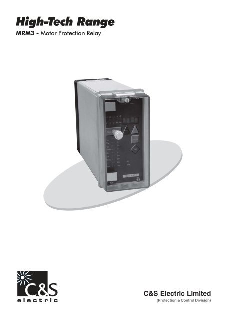
High-Tech Range<strong>MRM3</strong> - Motor Protection RelayC&S <strong>Electric</strong> <strong>Limited</strong>(Protection & Control Division)
<strong>MRM3</strong> - Motor Protection Relay5.7.3 Adjustment of the Trigger Event5.7.4 Pre-Trigger Time (T )vor5.8 Setting of the Clock5.9 Additional Functions5.9.1 Blocking of the Protective Functions5.9.2 Allocation of the Reset Functions5.9.3 Allocation of the Output Relays5.10 Measuring Value and Fault Indications5.10.1 Measuring Value Indications5.10.2 Units of the Displayed Measuring Values5.10.3Indication of the Fault Data5.10.4Fault Memory5.11 Reset5.11.1Erasure of the Fault Memory5.11.2Reset of the Thermal Memory5.12 Digital Inputs5.12.1Parameter Set Changeover Switch5.12.2External Trigger of the Fault Recorder5.12.3Recognition of “Motor Running” Condition5.12.4Undelayed External Trip5.12.5Delayed External Trip6 Notes on Relay Tests and Commissioning6.1 Connection of the auxiliary voltage6.2 Testing of Output Relays and LEDs6.3 Test circuit for <strong>MRM3</strong>6.3.1 Checking of Input Circuits and of theMeasuring Values6.3.2 Testing the START-STOP-RUNNINGRecognition6.3.3 Testing the Pick-Up and Disengaging Values6.3.4 Testing the maximum starting time6.3.5 Testing the thermal image6.3.6 Testing the Control Inputs6.3.7 Testing the CB Failure Protection6.4 Primary Test6.5 Maintenance7 Technical Data7.1 Measuring input7.2 Common data7.3 Setting ranges and steps7.3.1 System parameter7.3.2 Time overcurrent protection7.3.3 Load Unbalance Protection7.3.4 Earth fault protection7.3.5 Circuit breaker failure protection7.3.6 External trip delay7.3.7 Trip blocking beginning with theadjusted rated current7.3.8 Start parameter7.3.9 Interface parameter7.3.10Fault recorder parameter7.4 Tripping characteristics7.4.1 Tripping characteristic for max. startingtime7.4.2 Thermal image7.4.3 Initial load factor7.4.4 Tripping of t2x and t6x - times7.4.5 Inverse time overcurrent protection7.5 Trip characterisitcs7.5.1 Inverse Time Characteristic for LoadUnbalance7.6 Output relays8 Order form3
<strong>MRM3</strong> - Motor Protection Relay1 Introduction and ApplicationThe motor protection relay <strong>MRM3</strong> offers reliable protectionfor LV and MV motors which are either operatedvia power contactors or power circuit breakers. Thefollowing functions are integrated into this relay: Overload protection acc. to IEC 255-8 in consideration of the initial load factor (thermal image) Definite undercurrent protection Definite time overcurrent protection (DMT) Inverse time overcurrent protection (IMT) with selectable trip characteristics Short-circuit protection Load unbalance supervision with definite or inverse tripcharacteristics Earth-fault detection with suppression of harmonicsThe <strong>MRM3</strong> recognises the “Start-Up“ and “Motor Running“phase.Motors with a limited number of starts can be controlledby the start limiting function of the relay.The earth-fault supervision is either realised in Holmgreenconnection or by means of a core-type currenttransformer.The motor can be stopped in delayed or undelayedmode via digital inputs.The <strong>MRM3</strong> is available with rated currents of 1A or 5A.Important:For additional common data of all MR-relays pleaserefer to manual “MR - Digital Multifunctional relays”.On page 45 of this manual you can find the validsoftware versions.2 Characteristics and Features Microprocessor technology with self-supervision, Measuring of phase currents as RMS value, Digital filtering of the earth current with discrete Fourier analysis, by which the influence of interferencesignals, such as harmonics and transient DC components during an earth-fault are suppressed. Two sets of parameters, Operating hour meter, Complies with the requirements of IEC 255-8,VDE435, part 301-1 for overload relays, Definite time undercurrent protection, Selectable protective functions : Definite time overcurrent protection (DMT) and inverse time overcurrentprotection (IMT) Selectable IMT trip characteristics of IEC 255-4:Normal inverse (Type A)Very inverse (Type B)Extremely inverse (Type C)Special-purpose characteristics Reset mode for DMT/IMT trip characteristics is selectable, Definite element for short-circuit high-speed trip Single-step earth fault supervision, Load unbalance protection with inverse or definitetrip characteristics (NPS), CB failure protection, Display of the measuring values as primary quantities, Measuring of the phase currents during short-circuitfree operation, Blocking of the individual protective elements or thetrip elements can be set freely, The protective functions can be freely allocated tothe output relays. (Relay Matrix), Suppression of an LED indication after activation(LED flash), “Manual/Automatic“ reset function of the trip elementsadjustable via the configuration matrix, Saving of trip values and the switch-off times (tCBFP)of25 fault events (voltage fail-safe) Recording of up to 8 fault events with time stamp, Display of date and time, Trip via digital inputs, Rack mounting, with self-acting short-circuit mechanismfor CT circuits, Possibility of serial data exchange via the RS485 interface,optionally with CSE RS485 Pro-Open-DataProtocol or Modbus Protocol.4
3 Design<strong>MRM3</strong> - Motor Protection Relay3.1 ConnectionsL1L2L3L+/L L-/NC9 E9D9D8C8E8A2 A5 A6 A7 A8P1P2S1S2P1P2P1S1S2P1P2S1S1S2B3B4B5B6B7B8B1PowerSupplytt(IB.K)~tI>NINV- normal inverseVINV-very inverseEINV-extremely inverseDEFT-definite timeI>>t IE>t I>>NINVVINVEINVDEFTICommonResetBlockingSELECT/RESET+-ParameterswitchENTERExt. Trippingfor FRMotor isrunningExt. TripImmediatelyExt. TripdelayedRelay 1Relay 2Relay 3Relay 4D1C1E1D2C2E2D3C3E3D4C4E4D5C5E5D6C6E6D7P2S2B2I E>NINVVINVEINVDEFTITRIPSelfsuupervisionSerial InterfaceNGPNGPC7E7Figure 3.1 : Connection Diagram <strong>MRM3</strong>L1L2L3L1L2L3P1P2S1S2B3B4L1.1L1.2I1*P1P2S1S2P1P2S1S2B5B6B7B8L2.1L2.2L3.1L3.2I2I3S1S2B1B2IEB1B2IEFigure 3.2: Measuring of phase currents andearth current detection in Holmgreenconnection (IE)This kind of connection can be used where threephase CTs are available and a combination of phase andearth current measuring is required.Figure 3.3: Measuring of earth current withcore-type CT (IE)With the combination of phase and earth currentmeasuring, CTs to be connected according to Figure 3.2and Figure 3.35
<strong>MRM3</strong> - Motor Protection Relay3.1.1 Analog InputsThe analog input signals of the phase currents I L1(B3 -B4), I L2(B5 - B6), I L3(B7 - B8) and the earth current I E(B1 - B2) are fed to the protection device via separateinput CTs.The current measuring quantities are galvanical decoupled,analogously filtered, and then fed to the analog/digital converter.3.1.2 Output RelaysThe <strong>MRM3</strong> has 5 output relays. Two of these relays withtwo change-over contacts and three relays with onechange-over contact each are used for signalling. Theprotective functions can be freely allocated except of thosefor the self-supervision relay. Relay 1: C1, D1, E1 and C2, D2, E2 Relay 2: C3, D3, E3 and C4, D4, E4 Relay 3: C5, D5, E5 Relay 4: C6, D6, E6 Relay 5: Self-supervision C7, D7, E7All relays are operating according to the n. o. principlewith the exception of the self-supervision relay, whichoperates acc. to the n. c. principle.3.1.4 Low/High Range of the DigitalInputsThe <strong>MRM3</strong> is equipped with a wide-range power supplyunit and hence the supply voltage is freely selectable. Theswitching threshold of the digital inputs, however, has to befixed in compliance with the supply voltage. Two differentswitching thresholds can be adjusted:Range Plug Unot activeUactiveLow Plugged in = 10VHigh Open =70VL1I2L2L3hERSFR7 6 5 4 3 2 13.1.3 Digital InputsThe <strong>MRM3</strong> has 7 digital inputs with fixed functions. Allinputs have a common reference point : Terminal D8.(See Chapter 3.1)I B> t> k CCHARNo.CBBlock0Startt>>II>>I2>IE>TripP2SRENTERTRIP<strong>MRM3</strong>No Terminal Function CodingPlug1 C8 External reset 22 E8 External blocking 13 A2 Parameter set change- 3over switch4 A5 External trigger for the 4fault recorder5 A6 Identification “Motor- 7Running“6 A7 Ext. trigger, undelayed 67 A8 Ext. trigger, delayed 5Figure 3.4 : Coding plug6
<strong>MRM3</strong> - Motor Protection Relay3.2 Front plateThe LEDs ϑ, h, RS and FR on the <strong>MRM3</strong> emit a yellow light,all other LEDs are bi-coloured. The LEDs at the left next tothe alphanumerical display give a green light during measuringand a red one when a fault signal occurs.L1 L2L3 EThe LEDs underneath the - push buttonemit a green light during adjustment and inquiry of thesetting quantities left to the LEDs. They show a red light ifthe printed setting quantities right to the LEDs are activated.I2hRS FR3.2.1 Indicating LEDsSELECT/RESETI B> CNo.CHARCBBlock0Startkt>>II2>I>>IE>TripP2S/R-+ENTERTRIPL1, L2, L3 Indication of the phase currentsEIndication of the earth currentI2Indication of the unbalanced loadcurrent (NPS)ϑIndication of the temperature equivalenthOperating hour meterDate and time<strong>MRM3</strong>3.2.2 Adjusting LEDsFigure 3.5 : Front plate <strong>MRM3</strong>-IEL1 L2I B><strong>MRM3</strong>L3I2 hRS FRSELECT/RESET CNo.CHARCBBlock0Startkt>>II2>I>>TripP2S/R-+ENTERTRIPIB>Rated motor currentK Constant quantity (k*IB = 100%thermal load)τ WHeating period constantτ CCooling down factort> Tripping times, generallyϑ> Switching threshold of the thermaloverload alarmNo.Number of motor startsCHARCharacteristics settingI< Undercurrent settingI> Overcurrent settingI2> Load unbalance setting (NPS)I>>Short-circuit settingIE>Earth current settingCBCB failure protectionBlockStart blocking/Protective blocking0 Current>0/
3.3 Analog partThe alternating currents injected by the CTs are convertedinto galvanical isolated voltages via input transmitters andburden in the analog part.The effect of inductive and capacitive coupled interferencesare suppressed by RC analog filters. The measuring voltagesare fed to the analog inputs (A/D transformer) of the microprocessorand then converted into digital signals by meansof sample and hold circuits. These digitised values are thenused for further processing. The measuring values areacquired at fn = 50 Hz (fn = 60 Hz) with a samplingfrequency of 800 Hz (960 Hz), and thus the instantaneousvalues of the measured quantities are acquired every 1.25ms (1.04 ms).3.4 Digital part<strong>MRM3</strong> - Motor Protection Relayto protective tripping.With the protection program, stored in the program storage(EPROM), the micro-processor processes the voltagesapplied to the analog inputs and from this calculates thefundamental harmonics of the current. Digital filtering(DFFT-Discrete Fast-Fourier-Transformation) for suppressionof harmonics as well as suppression of DC componentsduring the short-circuit is used in the process.The micro-processor compares the existing current withthe threshold value (setting value) stored in the parameterstorage (EEPROM) and up-dates the thermal image. If acurrent exceeds the threshold value for longer than the tripdelay or if the thermal image exceeds its rated value, afault signal occurs. Dependent on their settings, the outputrelays pick up as well. When setting the parameters, allsetting values are read-in by the micro-processor andsaved in the parameter storage.The protection relay is equipped with a powerful microcontroller,being the core element of the protection unit.With this micro-controller all tasks are completely digitallyprocessed, from discretisation of the measuring quantitiesThe program flow is continuously monitored by the incorporated“Hardware-Watchdog”. Processor failure issignalled by the “Selfsupervision” output relay.Blockingmatrix>100%DisplayII 2>100%TripTripIL1IL2IIV1I>tI>>I>AlarmI>>tripRoutermatrixRelay 3I>>AlarmI2>tI2>I2>tripRelay 4I2>AlarmIEIE>tIE>IE>tripIE>AlarmFigure 3.7 : Block Diagram of Protective Functions8
<strong>MRM3</strong> - Motor Protection Relay4 Working Principle4.1 Start RecognitionThe <strong>MRM3</strong> monitors the flow of the current from which thefollowing operational conditions of the motor are gathered. STOP START RUNNINGmax. start-up time[I]Direct startOverloadOverload threshold=IBxkRecognition*Motor running*Resistance startStart-up via invertercontrolRecognition *Motor running*e.g. star-delta switch-overMotor stopStart/Stop threshold=2% I nStartrecognitionStop time1.0s - 10.0s... or “motor running” recognitionStop time1.0s - 10.0s[t]Figure 4.1 : Different Start-Up Behaviour of MotorsSTOP - Condition:If no current can be measured (I < Stop threshold), STOPconditions are recognised after expiration of the stop time.Start/Stop ThresholdThis threshold is fixed at 2% of I NStop time:The Stop time is adjustable in order to tolerate a brief offtimeof the current flow (e.g. changeover Star/Delta) fromthe START or RUNNING conditions. STOP is only indicatedif the current was under 2% I for longer than the stopNtime. Based on this time the running down period can beconsidered in a certain way for the LED indication.START-Condition:START is only recognised if the previous condition wasSTOP and the motor current has exceeded the startthreshold. If the STOP or RUNNING conditions arerecognised, the START condition is terminated.Overload Threshold:This corresponds to the permissible thermal continuouscurrent k x IB and is adjusted by the parameter of thethermal image.Starter Recognition Time :This adjustable time has only to be extended for specialstart procedures in order to prevent that the RUNNINGconditions are indicated too early in advance.9
<strong>MRM3</strong> - Motor Protection Relay No exceeding of the start threshold during pony motorstart-up or when soft starters are used. Multistage resistance start where the start threshold iseither exceeded several times or not at all.The time is running from the instance the start threshold isexceeded. RUNNING is only accepted by the supervisionafter the time has elapsed or the overload threshold isundershot. If the overload threshold is not a clear criterion,the time has to be set at least for so long that the longestregular start procedure is covered.RUNNING can be recognised in different ways: If the START has been successfully completed. This isthe case when the motor current has dropped belowk x IB and the start recognition time has elapsed. (directstart) or if the motor is connected across several resistancesteps, it is possible that the start threshold is passedthrough repeatedly. RUNNING conditions arerecognised when the start recognition time has run outafter the last step and a current has settled between 2%IN and k x IB t.(Resistance start). if after STOP a motor current has settled between 2%IN and k x IB and the start recognition time has elapsed.The overload threshold has not necessarily to beexceeded.(soft start) If the «Motor Running» input was activated but theoverload threshold is not (or not any longer) exceeded.(See Chapter 5.12.3 )With the recognition of STOP, the RUNNING conditionshave ceased to exist.OverloadthresholdI = >(IBxk)&Start detectionI>2% of I nStop detectionI1 t20Max.Stoptime0&t1Start detectionor motor is runningSQRQSR>10t3Max.Start-timeBreak of startstart-timetoo longMessagemotor runningLED SRemit greenStartcounterElapsedhourmeter&Messagemotor startingLED SR flashI< stage andI> stage forblocking thestartphaseFigure 4.2 : Flow Diagram of the Start Conditions4.1.1 Criteria for Blocking the StartNumber of monitored starts :The <strong>MRM3</strong> is equipped with a flexible supervision elementwhich can limit the sequence of possible starts.The protective element can either be tied to the thermalimage or be manually defined by the number of starts andcycle duration.A start should be prevented if it is obvious that it is likely tobe interrupted due to overload so that in total the downtimecan be curtailed. If a start is not recommendable ata certain time (with the motor switched off), the <strong>MRM3</strong>activates an allocated output relay until the waiting time haselapsed. Irrespectively of the adjustment of this element,the thermal image is always activated and shuts the motordown as soon as the thermal overload threshold is reached(due to a start or overload).10
Number of Starts/Cycle Duration. These two are definedas parameters.Example:<strong>MRM3</strong> - Motor Protection Relay(t)Duration ofone intervalFixed start blocking timeThe motor should be allowed to be started three times anhour:This means that in theory the motor can be started every20 minutes (= 60 min/3).From this it can be concluded that the load generated bythe start procedure has decayed after these 20 minutes.If the motor would be successfully started three time inquick succession, an immediate fourth start wouldoverload the motor. The start blocking relay would beactivated and the next start would only be advisable afterabout 20 minutes. The protective element ensures that thestart sequence is kept within safe intervals but that at leastthree starts are allowed during the given time frame. If theintervals between each start are long enough then evenmore than three starts an hour might be possible becausethe motor was able to cool down in the mean time. Thedelay can be firmly defined (through start blocking time)or be automatically ascertained (VARI ) until the 20 minutesgiven in the example are over. The state of thethermal image has no influence on the delay.(t)Duration ofone intervalDuration of one intervalConnectedtimeStartblocking(VARI)Duration of one intervalFigure 4.4 : Relation Start Period/Start BlockingTime with firm Start Blocking TimeThermal ImageA start is always possible as long as there is enoughthermal reserve for a start. This start limitation is a dynamicone and is orientated on the data the thermal image isparameterised with. For this the <strong>MRM3</strong> detects the averagethermal load of the latest starts. With the motor shutdown, the start blocking relay is activated for the time whenthere is not enough thermal reserve in the storage throughcooling down to enable a new start.(t)(t)(t)ConnectedtimeDuration of one interval(t)( )100%RunningStartStartblocking(VARI)(t)Stop(t)(t)Figure 4.3 : Relation Start Period/Start BlockingTimeStartblocking(t)Figure 4.5 : Start Blocking through Thermal Image11
<strong>MRM3</strong> - Motor Protection Relay4.2 Starting timeWith certain applications it is possible that the startingphase of the engines is extended. One reason for thisinsufficient terminal voltage which may be caused by thehigh starting current or by a high grid load in general.When starting under load, the starting phases must not betoo long because this could overheat the motor.For these applications the <strong>MRM3</strong> offers a variable maximumstarting time. It refers to the rated starting current ofthe motor I_Start. If the actual starting current (e.g. at 80%U N) is lower than the rated starting current, the startingtime is extended automatically.Q = I ² x tsThe supplied heat energy is equal to the square value ofthe current times the starting time. If the starting currentdecreases, the starting time can be extended. This timecan be extended by a maximum of twice the set value. Ifthe actual starting current is higher than its rated value, themax. starting time decreases (refer to Fig. 7).4.3 Thermal ImageThe fed thermal energy Q and the temperature ϑ of themotor when in steady state condition is proportional to thesquare of the phase current (e.g. ohmic losses and ironlosses):Q ~ I ² oder ϑ ~ I ²In the thermal image this temperature is described by thetemperature equivalent ϑ (in %). For loading with themaximal permissible operational current k x I B, the motorreaches the maximal permissible temperature ϑ . if it hasBbeen in steady state condition for a certain time. For thisload the thermal equivalent is defined to 100% = tripthreshold:Stationary final value:I 2ϑ (%) =(k.I ) 2 *100%BNote:When testing the thermal image it has to be taken intoconsideration that in case k x IB is slightly exceeded (= longtripping time), a small current change within thepermissible measuring tolerances can cause a highdispersion of the tripping time (clearly by more than 1%).This is related to the slope of the trip characteristic.Furthermore it is important to start from the same initiallevel of the image when testing. Otherwise the trippingtimes may be shorter than expected.Automatic ResetDuring the starting process the <strong>MRM3</strong> observes the rise ofthe thermal image. From the average of the last twosuccessful starts the unit detects the start load. Afteroverload conditions, the thermal image is only releasedwhen the motor has cooled down far enough to deal withthe demand of a new start.4.4 Requirement on the Main CurrentTransformersThe CTs chosen have a considerable influence on theaccuracy of the protective system. In order to select theright type of transformer, the requirements and conditionson site have to be considered carefully.Type of TransformerCurrent transformers have to be designed as protectiontransformers (P).Overcurrent Factor:To ensure precise operation of the protection unit evenunder full short-circuit current, the chosen transformersmust not saturate in this current range. This means that theoverload factor must be sufficiently large.ClassFor the nominal range or the lower load range it has to betaken into account that not only the basic accuracy of the<strong>MRM3</strong> has to be considered but also the transformeraccuracy. This applies especially for cases where theHolmgreen circuit is used and for low earth fault currentsin isolated networks.Power RatingThe transformer must be rated sufficiently to cover allmeasuring instruments and protective devices connectedas well as the losses on the transformer measuring linewithout becoming overloaded.12
<strong>MRM3</strong> - Motor Protection Relay5 Operation and Adjustments5.1 Displayed text for parameter settingsFunction Displayed Text Related LED ReferencesNormal operationCSEExceeding the measuring range max. ϑSec. transf. currents indication SEK L1, L2, L3,E Chap. 5.3.1Rated frequency f = 50 / f = 60 Chap. 5.3.2LED flashing after activation FLSH/NOFL Chap. 5.3.5Parameter set change-over switch SET1, SET2, P2 Chap. 5.3.6Blocking of a function EXIT LED of the blockedparameterCharacteristics phase current DEFT,NINV, VINV, EINV,LINV, RINV, CHAR + I> Chap. 5.4.8Characteristics earth current DEFT, NINV, VINV, EINV,LINV, RINV, RXIDG CHAR + IE>> Chap. 5.4.15Characteristics DEFT, INVS CHAR + I2> Chap. 5.4.12Reset mode 0s / 60s CHAR + I> + t>CHAR + I2> + t> Chap. 5.4.10CHAR + IE> + t> Chap. 5.4.17Start blocking by thermal supervision AUTO Start + No Chap. 5.5.1Auto. definition of the remainingblocking time VARI Start + block + t> Chap. 5.5.3CB failure protection CBFP CB + t> Chap. 5.4.18Inquiry of the fault memory FLT1, FLT2.... Trip = type dependent Chap. 5.10.3Erase fault memory wait Chap. 5.10.4Relay tripped TRIP Trip = type dependentReset the systemCSEPassword inquiry PSW? LED of the set parameterHidden password „XXXX“ Chap. 5.2Parameter to be saved?SAV?Save parameter !SAV!Manual tripTRI?Blocking of the protec. function BLOC, NO_B, PR_B, TR_B LED of the set parameterRelay assignment z. B. _ 2 _ _ LED of the set parameterTrip signal for the fault recorder P_UP; A_PI; TRIP; TEST FR Chap. 5.7.3Number of fault events S = 2, S = 4, S = 8 FR Chap. 5.7.2Indication of date and time Y = 01, M = 01, D = 04,h = 12, m = 2, s = 12 Chap. 5.8Slave address of the serial interface 1-32 RS Chap. 5.6.1Baud-Rate 1) 1200-9600 RS Chap. 5.6.2Parity-Check 1) even odd no RS Chap. 5.6.3Table 5.1: Indication Possibilities via the Display1) Modbus only13
5.2 Setting Procedureshort advancing the indicationlong resetSaving of an entry<strong>MRM3</strong> - Motor Protection Relay5.3.3 Operating Hour Meter (h)As soon as the conditions START or RUNNING have beenrecognised, the operating hour meter starts. The metercan also be preset. Years and hours are shown in twowindows. After every 8760 h the value is carried over tothe window ”Year”.In the display the years are marked with the letter “Y”(engl.: year)Before parameters can be set a password is inquired (seechapter 4.4 of descrip. ”MR – Digital Multifunction Relay”).5.3.4 Number of Motor Starts (No.)5.3 System parameters5.3.1 Presentation of Measuring Values asPrimary Quantities on the Display(I primPhase)This parameter makes it possible to present the indicationsof phase current and earth-fault current separately, i.e asprimary or secondary measuring value. Currents in thekiloampere range are indicated with the symbol of unit ofmeasurement k (kilo) as three-digit point.Example:A 1500/5 A CT is used with a primary current of 1380A. The parameter for the CT primary current is given inkiloampere. The parameter is set to ”1.50“ (kA). Then ”1K38“is displayed as I-measurement. If the setting is set to ”sec.“, ”0.92“ x I N. is displayed asI-measurement.Note:The settings for the pick-up value are adjusted to a multipleof the secondary rated CT current.The settings for phase and earth current transformers canbe done separately.5.3.2 Rated -FrequencyEvery start is counted, even unsuccessful ones. Thenumber of motor starts can be preset.5.3.5 Indication of pickupIf the momentary current drops below the pickup threshold,e.g. I>, after the relay was activated and there was notripping, then the activation is signalled by short flashing ofLED I>. The LED keeps flashing until the pushbuttonis pressed. By setting the parameter to FLSH/NOFL,flashing can be suppressed.5.3.6 Parameter Set Changeover Switch(P2)By means of this switch two different parameter sets can beactivated. The changeover procedure can be realisedeither by the software or via the digital input (A2). If theparameter set changeover switch is adjusted to ”SET2“,the active parameter set can be changed to ”SET1“ via theexternal input. If the changeover switch is set to ”SET1“,then it can be changed to ”SET2“ via the digital input. Thedigital input does not change this parameter.The LED P2 on the front cover always indicates which ofthe parameter sets is active. Furthermore it is possible toindicate via an assigned output relay that parameter set 2is active.During the setting procedure the LED P2 gives off a yellowlight.The FFT-Algorithm used for the data acquisition needs theset point of the rated frequency, i.e. 50 Hz or 60 Hz, forcorrect digital filtering of the earth current.14
<strong>MRM3</strong> - Motor Protection Relay5.4 Protection Parameters5.4.1 Thermal Overload Protection (k x I B)With the product of setting values k x I Bthe continuouslypermissible maximal current of the motor is adjusted. Atthis current the thermal image reaches 100 % after a longperiod – i.e. the trip threshold. With I Bnormally the ratedcurrent of the motor is adjusted and with k an overloadfactor (e.g. 1.05)It is also possible to adjust the maximal continuous currentdirectly, if k = 1 was selected.5.4.2 Warning/Tripping with thermalOverloadSometimes it is necessary that the thermal protectionbeyond the 100 % limit does not lead to shut-down (e.g.fire extinguisher pump). For this reason it is possible todifferentiate between tripping and warning. In case of thewarning function the display does not show “TRIP”. Therelay assigned to this step responds and should thereforebe configured onto a different relay than the one leadingto tripping.5.4.4 Heating Period Constant τ WandCooling-Down Time Factor τ CWith this time constant the thermal image is adapted to theheating behaviour of the motor. It is the time constant of ane-function.Normally the motor is cooling down with a slower timeconstant. Parameter τ Cis to be understood as a factor. Thecooling-down behaviour in the thermal model proceedswith the time constant τ Cx τ W.If τ C= 1 is selected, thenheating and cooling-down proceed at an identical speed inthe thermal image.5.4.5 t2x and t6x Minimal Trip Time Duringthe Starting Process.With this parameter the fastest trip time during the startupphase is limited for the thermal image. If the selected pickupvalue k x IB is exceeded by two times or six times, thecharacteristic breaks to definite time. This prevents that ahigher start current causes the thermal image to overflowat the first instant. Normally six times the value is selected.If not desired, the characteristic can be operated withoutbreaking by setting EXIT.5.4.6 Phase Undercurrent Element (I is exceeded. Thewarning relay responds and the LEDs signal excitation.Excitation signalling remains active beyond the startingphase as well. Since starting of the motor is a normalprocess and not a malfunction, it is possible at this point todelay detection of the excitation for thermal overload. Ifthe motor is overloaded often and this is permissible for ashort period (e.g. breakers) it may also make sense tooperate this overload with delay action. This delay is alsoeffective in motor OPERATING mode and has no effect onthe tripping behaviour of the <strong>MRM3</strong>.Running-dry protection/V-belt splitThe <strong>MRM3</strong> trips if after a successful start the current liesbelow the adjusted current threshold for a definite time.Undercurrent is only active during mode RUNNING. Theundercurrent element is also blocked if the measuredcurrent lies below the STOP threshold (see chapter 4.1).EXIT is set, then this element is switched off.The time delay for the undercurrent element is set toseconds.Note:The time delay must not be set shorter than the STOP time,otherwise every time the motor is stopped, an undercurrenttrip occurs.15
<strong>MRM3</strong> - Motor Protection Relay5.4.7 Phase Overcurrent Element (I>)When adjusting the pick-up value for the phase overcurrentelement I>, an indicating value, referring to thesecondary rated current I N, is displayed. This element isonly active during mode RUNNING.5.4.8 Trip Characteristics for the PhaseOvercurrent Element (I>+CHAR)There are the following standard trip time characteristicsavailable (see 7.5):DEFT - Definite Time (definite timeovercurrent protection)NINV - Normal inverseVINV - Very inverseEINV - Extremely inverseRINV - RI-InverseLINV - Long term InverseIf the tripping time or time factor are set to infinite long (onthe display “EXIT” is shown) then trip of the relayovercurrent element is blocked. The WARNING/ALARMfunction is still active. During this time LEDs I> and t> arered.5.4.10 Reset Mode for the Trip Characteristicsin the Phase Current Path(I>+CHAR+t>)In order to ensure that the trip function is reliable even withrepeated error pulses, each of them shorter than the settripping time, the RESET mode for the trip characteristicscan be changed over. With a setting of “60s“ the elapsedtripping time is frozen and is only reset after 60s faultlessoperation. Should another fault occur within these 60s, thetripping time counter remains in operation. With the setting“_ 0s“ the counter is immediately reset when the faultcurrent is interrupted and it is restarted when the faultcurrent has returned again.5.4.11 Phase Short-Circuit Trip (I>>) and(I>>+Start)5.4.9 Tripping Time or Time Factor for thePhase Overcurrent Element (I>+t>)Normally, after change of the trip characteristics, thetripping time or the time factor also has to be changedaccordingly. In order to avoid an unsuitable combinationbetween trip characteristics and tripping time or timefactor, the following measures are initiated by the <strong>MRM3</strong>:The LED for adjustment of the tripping time or time factor(I> + t>) starts to flash after the trip characteristics havechanged. By this warning signal the operator is remindedto adjust the tripping time or time factor to the changedoperational mode or trip time characteristics. This warningsignal keeps flashing until the tripping time or time factorare re-adjusted. If re-adjustment has not been done within5 minutes (the time to enable parameter setting), then theprocessor sets the tripping time or time factor to the highestsensible value (smallest possible tripping time ).When adjusting to the “Definite Time” trip characteristic,the definite tripping time displayed is shown as seconds(e.g. 0.35 = 0.35s). By pressing pushbuttons this time can be changed step by step in the range 0.04s– 260sThe short-circuit element has two threshold values andtwo time delays. The first threshold value applies forthe mode RUNNING and the second one for modeSTART.Possible variations are: During the start procedure the existing inrush currentcan be higher than the desired short-circuit thresholdduring operation. e.g. direct start) It is also possible that the slip rings are put at riskespecially during the start procedure so that for STARTa more sensitive adjustment is required than forRUNNING. Both elements can be set to the same value so there isno differentiation.If it is set to EXIT then the respective element is switchedoff.Irrespectively of the selected trip characteristics for I>, theshort-circuit high-speed trip element I>> has a trippingtime which does not depend on the current. This time.applies for both elements I >>STARTand I>>RUNNINGWhen adjusting to the “Inverse Time” trip characteristics,the time factor (tI>) is displayed. This factor can bechanged also by push buttons step by step in therange 0.05 – 20.0.16
<strong>MRM3</strong> - Motor Protection Relay5.4.12 Negative Phase SequenceLoad unbalance can, for example, be caused by a phasefailure or fault in a one motor winding.Load unbalances give rise to negative phase sequencecurrents in the stator, causing odd harmonics in the statorwinding and even harmonics in the rotor winding.Especially the rotor is endangered by this becauseasymmetric conditions mean additional thermal stress forthe rotor winding and eddy currents are induced in thesolid iron of the rotor which can cause destruction of themetal structure or even melting of the metal.Within certain limits and by observing the ultimate thermalstrength of the motor, load unbalance is permissible,though. The details given by the motor manufacturermostly refer to the negative phase sequence system andthus can be programmed directly.According to the method of “Symmetric Components“, arotating three-phase system can be sectionalised into apositive phase sequence system, negative phase sequencesystem and a zero phase sequence system. The current inthe negative phase sequence system is the measure forthe load unbalance quantity. The effective value of thecurrent of the negative phase sequence system I 2iscalculated by the <strong>MRM3</strong>.When setting the threshold value for the load unbalancecurrent I 2>, the indicated value referring to the ratedcurrent (I N). is displayed.When adjusting the trip characteristics either « DEFT » for“definite” trip characteristics is shown on the display or«INVS » for “inverse” trip characteristics. (see chapter7.4.7)5.4.13 Earth Fault Element (I E>)The setting procedure outlined in chapter 5.4.5 applieshere as well. The required value in the 0.01 x I – 2.00Nx I range can be set with push-buttons and .N5.4.14 Switching Over Warning/TrippingAn earth fault can be parameterised as follows. After thedelay time has expireda) the warning relay responds (warning)b) the tripping relay responds (tripping)The tripping values are stored in the fault recorder.5.4.15 Trip Characteristics for the Earth-Fault Element (I E>+CHAR)When adjusting the trip characteristics one of the following7 abbreviations is displayed:DEFT - Definite Time (definite time overcurrent protection)NINV - Normal inverse (Type A)VINV - Very inverse (Type B)EINV - Extremely inverse (Type C)RINV - RI-InverseLINV - Long-term inverseRXID - Special purpose characteristicsThe displayed text can be changed by push-buttons . By pressing the required tripcharacteristics is selected. The allocated LED I E> is red, theLED CHAR green.5.4.16 Tripping Time or Time Factor for theEarth Fault Element (I >+t>)EThe setting procedure outlined in chapter 5.4.9 applieshere as well.5.4.17 Reset Time for the Earth FaultElement (I E>+CHAR+t>)The setting procedure outlined in chapter 5.4.10 applieshere as well.5.4.18 Tripping Time for the CB Failure-Protection (CB+t>)This protection is activated after a protective trip and itmonitors if all phase currents have dropped within theset time t CBFPto )Via the digital input A8/D8 an external trip with time delaycan be activated. Trip is initiated if the
<strong>MRM3</strong> - Motor Protection Relay5.4.20 Trip Blocking in case of ExcessivePhase Current (Trip+Block)This function is important where power contactors areused and they are not designed to disconnect high shortcircuitcurrents. In such a case no function of the <strong>MRM3</strong>must initiate tripping. The trip function is then allocated toa preceding protective element (e.g. fuse).Trip blocking is activated as soon as the set current isexceeded. When this threshold is undershot, all functionare released again.If the circuit breakers used are able to disconnect theshort-circuit current to be expected, the function is set toEXIT.5.5 Start SupervisionThe <strong>MRM3</strong> can offer two start supervision methods: Automatically by means of the thermal load By a limited number of starts per time intervalVARIA new start is possible after the remaining time of theinterval has run down.Time Adjustment (s):Restarts are blocked for the adjusted time.5.5.4 Characteristic for the Starting TimeIn some motor applications it may happen that the supplyvoltage is lower than the rated value. Lower rated valueshave lower starting currents and consequently longerstarting times. The starting time can be extended byselecting a characteristic. The setting “DEFT” means that amaximum starting time is fixed. The subsequent parameter“Rated starting current” is not active. The setting “INVS”means that the maximum starting time is variable. It isdetermined by the rated starting current and thepermissible starting time at rated voltage (refer to Chapter7.4.1).5.5.5 Rated starting current I_Start5.5.1 Duration of a Start Cycle (No.+Start)AUTOIf this mode is selected, a start is always possible if sufficientstart reserves are available according to the thermalimage. This function operates dynamically on the data ofthe previous starts (see chapter 4.1.1).Time AdjustmentBy this the interval of the permissible number of starts istimed.The number is defined in the next parameter.EXITThe element is de-energised.5.5.2 Number of Starts per Cycle(No.+Start)This parameter is only visible if a time was selected withthe preceding parameter which defines the number ofpermissible starts during the respective interval.5.5.3 Start Blocking Time (Start+Block+t>)The basis for calculating the maximum starting time is therated starting current I_Start of the motor at rated voltage.5.5.6 Maximal Start Time (Start+t>)Exceedingly long acceleration can only be recognised ifthe threshold k*I Bis once overshot after the STOP thresholdwas exceeded.With the setting “DEFT”The time meter for the max. start time is activated uponexceeding of the threshold k*I B>. If the set time has elapsedand the current lies (still or again) above the STARTthreshold, the start procedure is stopped. When modeRUNNING is recognised, this element is deactivated untilthe next start attempt.With the setting “INVS”If the characteristic is selected for the maximum startingtime, this parameter is valued as rated starting time/timemultiplier ts and multiplied by the calculated tripping time.Example: If the starting current is lower than the ratedstarting current by the factor 0.707, the maximum startingtime is doubled (refer to Chapter 7.4.1).This parameter is only visible if a time was selected(chapter 5.5.1). It defines the time for a new start whenthe number of starts per interval was exceeded. Thefollowing is possible:18
<strong>MRM3</strong> - Motor Protection Relay5.5.7 Start-up recognition time or MotorRunning timeThe start-up recognition time is a criterion for switchingover to OPERATION. The <strong>MRM3</strong>-e recognises the operatingmode if the threshold IB*K> is fallen short of andthe start-up recognition time has expired. (refer to Chap.4.1)5.5.8 Stopping timeA motor is considered to be stopped if the measuredcurrent has fallen short of the value
<strong>MRM3</strong> - Motor Protection RelayTpretrigger occurrencerecording durationTESTData saving is activated whenpushbuttons and are pressedsimultaneously (immediately upon pressing the buttons). For recording time, themode TEST is displayed.[s]5.7.4 Pre-Trigger Time (T vor)Figure 5.2: General Set-Up of the Fault RecorderEach of the storage segments have a fixed storage timewhere the time before the trigger event can be defined.The time T predefines the period to be saved prior to thetrip event. This time can be set between 0.05 s and themax. recording time (2, 4 or 8 s). With pushbuttons and the values can be changed and with they can be saved.Via the RS485 interface the data can be read out bymeans of a PC provided with HTL/PL-Soft4. The data isgraphically edited and represented. Binary tracks arerecorded additionally, e.g. activation and trip.5.8 Setting of the ClockWhen date and time are set, the LED „“ is on. Thefollowing method is used:5.7.2 Number of Fault RecordingsThe max. recording time is 16 s at 50 Hz or 13.33 s at60 Hz.The max. number of recordings to be stored has to bedefined beforehand. There is the choice between (1)* 2,(3)* 4 and (7)* 8 recordings. Hence the existing memoryspace can be used as follows:(1)* 2 recordings for 8 s at 50 Hz and 6.66 s at 60 Hz.(3)* 4 recordings for 4 s at 50 Hz and 3.33 s at 60 Hz.(7)* 8 recordings for 2 s at 50 Hz and 1.66 s at 60 Hz.* will be overwritten when a new trigger signal occurs.5.7.3 Adjustment of the Trigger EventThere is the choice between four different trigger events:Date: year Y=00month M=00day D=00time: hour h=00minute m=00second s=00Immediately when the supply voltage is applied the clockstarts with the respective date and time. The time isbuffered against short-term voltage failures (min. 6minutes).Note:The window for setting the clock is behind the measuringvalue reading. Access to the window via pushbutton.P_UP (PickUP)TRIPData saving begins when a generalactivation is recognised.Data saving begins when a generatrip is recognised.A_PI (After Pickup)Data saving begins when the lastactivation threshold is undershot(recognises, for instance, CB failureprotection)20
<strong>MRM3</strong> - Motor Protection Relay5.9 Additional Functions5.9.1 Blocking of the Protective FunctionsBlocking of the protective functionsAfter voltage has been applied to blocking input D8/E8,the intended reaction for each of the protective functionscan be defined individually. (Observe voltage adjustment!) See chapter 3.1.4Setting Effect when voltage has been appliedto the blocking inputPR_B Complete blocking of the protective element.Activation and trip are suppressed.TR_B Blocking of trip elements.The individual protective elements areactivated and this is signalled accordingly, butthere is no tripping.BLOC Complete blocking of the protective element.Activation and tripping are suppressed. This is displayed if it is not differentiatedbetween PR_B and TR_B in aparameter.NO_B No blocking.This element operates normal, it is notblockedTable 5.3: Adjustment PossibilitiesSetting of parameters should be done as follows: To come to the blocking menu push-buttons and are to be pressed at thesame time. The function being set is indicated byLEDs. If necessary the blocking function can be changedwith or and saved with Perhaps a password has to be entered. Proceed to the next function with After selection of the last blocking function settingsfor the 2 nd parameter set can follow. For allocating the RESET function press push-button again. (See next chapter).Symbol Protective Function Default Possible Settings LED/ColourSettingϑ> Overload warning element NO_B NO_B ; BLOC ϑ> redI B> x k Overload element NO_B NO_B ; PR_B ; TR_B I B> green/τ greenWI< Undercurrent element NO_B NO_B ; PR_B ; TR_B I< redI> Overcurrent element NO_B NO_B ; PR_B ; TR_B I> redI>> Start Short-circuit element at start-up BLOC NO_B ; PR_B I>> red/Start greenI>> Short-circuit element during operation PR_B NO_B ; PR_B ; TR_B I>> redI2> Load unbalance element NO_B NO_B ; PR_B ; TR_B I2> redI E> Earth current element NO_B NO_B ; PR_B ; TR_B I E> redtCBFP CB failure protection NO_B NO_B ; BLOC CB greenTrip External trip NO_B NO_B ; BLOC Trip redTable 5.4: Default Setting of the Blocking Functions21
5.9.2 Allocation of the Reset Functions<strong>MRM3</strong> - Motor Protection RelayWhen setting of the parameters for the blocking functionis completed you are in the allocation mode for the resetfunctions. Whether the assigned relay should be resetmanually or automatically after activation or trip can beallocated to each of the activation or trip elements. Whichof the reset function If necessary the reset function can be changed with or and saved with Perhaps apassword has to be entered. Proceed to the next function with After selection of the last reset function settings for the2 nd parameter set can follow. For allocation of the output relays press pushbutton again. (See next chapter).Symbol Protective Functions Default Possible Settings LED/ColourSettingϑ> Overload warning AUTO HAND ; AUTO ϑ> redI B> x k Overload alarm AUTO HAND ; AUTO I B> greenI B> x k Overload trip AUTO HAND ; AUTO I B> green/τ greenWI< Undercurrent alarm AUTO HAND ; AUTO I< redtI< Undercurrent trip AUTO HAND ; AUTO I< red/t> redI> Overcurrent alarm AUTO HAND ; AUTO I> redtI> Overcurrent trip AUTO HAND ; AUTO I> red/t> redI>> Start Short-circuit tripping when AUTO HAND ; AUTO I>> red/t> red/starting*Start greenI>> Start Short-circuit tripping during oper. AUTO HAND ; AUTO I>>redtI>> Start/op. Short-circuit tripping during oper. AUTO HAND ; AUTO I>> red/t> redI2> Load unbalance alarm AUTO HAND ; AUTO I2> redtI2> Load unbalance trip AUTO HAND ; AUTO I2> red/t> redI E> Earth current alarm AUTO HAND ; AUTO I E> redtI E> Earth current trip AUTO HAND ; AUTO I E> red/t> redtCBFP CB failure protection AUTO HAND ; AUTO CB greenTrip External trip AUTO HAND ; AUTO Trip redTable 5.5: Default setting of the Reset Functions* Short-circuit excitation during starting always has automatic reset22
<strong>MRM3</strong> - Motor Protection Relay5.9.3 Allocation of the Output RelaysThe <strong>MRM3</strong> has five output relays. The fifth output relay isan alarm relay for the self-supervision and its allocation isfixed; it is operated acc. to the closed circuit principle.Output relays 1 - 4 can be freely allocated to the currentfunctions either as alarm or trip relay; they are operatedacc. to the open circuit principle. Allocation of the outputrelays is similar to the parameter setting method in theBLOCKING mode or RESET mode. TThe allocation mode is activated with the last actuation ofthe push-button in the RESET mode (asexplained above).Each of the protective functions has two states:AlarmThis state is active, as soon as the setting value of theelement is exceeded.TripThis state is active after the time of the trip delay haselapsed.The adjustment procedure is as follows:Allocation of one or more of the 4 output relaysto “Alarm” or “Trip” of each of the protective functions.Which of the function is just being processed is signalledby the LEDs.Indication LED Allocated relay(s)_ _ _ _None1 _ _ _ 1_ 2 _ _ 2... ..._ 2 3 4 2, 3 and 41 2 3 4 allBy pressing push-buttons and all possiblecombinations can be realised. The selected allocation canbe saved by and subsequent entry of thepassword.Any allocation mode can be stopped by pressing the button for a certain time (about 3s).Note: Coding plugs J2 and J3, described in the generaldescription „MR- Digital Multifunctional Relay“have no function in the <strong>MRM3</strong>. At the end of this description an Adjustment Listcan be found in which the customer-specific adjustmentscan be filled-in.In addition to the protective functions special-purposesignals can be given by the relays: Startblock START LAUF(Start is not recommended)(Motor is starting)(Motor in operation)23
<strong>MRM3</strong> - Motor Protection RelayRelay functions Output relays Displayed Correspondingfigures LEDSymbol Function 1 2 3 4ϑ> Alarm X _ 2 _ _ ϑ> redI B> x k Alarm X _ 2 _ _ I B> greenI B> x k Tripping X 1 _ _ _ I B> green/τ WgreenI< Alarm X _ 2 _ _ I< redtI< Tripping X 1 _ _ _ I< red/t> redI> Alarm X _ 2 _ _ I> redtI> Tripping X 1 _ _ _ I> red/t> redI>> Alarm X _ 2 _ _ I>>red/Start greenI>> Start Tripping X 1 _ _ _ I>> red/t> red/Start greenI>> Alarm X _ 2 _ _ I>>redtI>> Tripping X 1 _ _ _ I>> red/t> redI2> Alarm X _ 2 _ _ I2> redtI2> Tripping X 1 _ _ _ I2> red/t> redI E> Alarm X _ 2 _ _ I E> redtI E> Tripping X 1 _ _ _ I E> red/t> redTripping _ _ _ _ CB greentCBFPExt. Trip Tripping X 1 _ _ _ Trip redUndelayedExt. Trip Tripping X 1 _ _ _ Trip red / t> redDelayedStart/Block Start blocking X _._.3._ Start green/Block greenStart Motor starting _ _ _ _ Start greenOperation Motor running X _ _ _ 4 S/R greenStart time Excessive start- X 1 _ _ _ Start green/t> reding timeTable 5.6: Example of an Allocation Matrix of the Output Relays (Default Setting))5.10 Measuring Value and Fault Indications5.10.1 Measuring Value IndicationsThe following measuring values can be displayed during normal operation: Current in phase 1 (LED L1 green), Current in phase 2 (LED L2 green), Current in phase 3 (LED L3 green), Earth current (LED E green), Load unbalance current (LED I2 green), Temperature equivalent ϑ> in % (LED ϑ> green), Operating hours (LED h yellow) Number of motor starts (LED No. green) Time until tripping in min. (LED Trip/t> red) Remaining time of start blocking in min. (LEDStart/Block green and t> red) Date and time (LED green)24
<strong>MRM3</strong> - Motor Protection Relay5.10.2 Units of the Displayed MeasuringValuesIndication of the measuring value can be represented inthe display optionally as multiple of the secondary ratedcurrent (x In) or as primary current (A).Consequently the units displayed are changing, i.e. for:Phase CurrentIndicated as Range UnitSecondary current .000 – 40.0 x InPrimary current .000 – 999. Ak000 – k999 kA*1k00 – 9k99 kA10k0 – 99k0 kA100k – 999k kA1M00 – 2M00 MA* for rated transformer current starting at 2kAEarth CurrentIndicated as Range UnitSecondary current .000 – 15.0 x InPrimary earth cur- .000 – 999. Arent k000 – k999 kA*1k00 – 9k99 kA10k0 – 99k0 kA100k – 999k kA1M00 – 2M00 MA* for rated transformer current starting at 2kA5.10.3 Indication of the Fault Dataevents. If this number is exceeded, the eldest data set isthen overwritten.Besides the tripping values, the LED states are also savedfor fault indication.Inquiry of the fault memoryWhen the push-button is pressed during normalmeasuring value indication, the fault data is displayed.FLT1 last faultFLT2 fault before last etc.By pressing the respective fault can be selected.During fault value indication FLT it can be changed over to another fault data set bypressing or it is displayed, which of the parameter sets was activeduring the event the LEDs are flashing according to the stored pick-upvalues/trip information, i.e. LEDs showing a permanentlight when the trip occured, start to flash in order toindicate that is was a past fault condition. Those LEDs,which were flashing when the trip occured, (elementwas actuated) are flashing briefly the individual fault measuring values for the respectivefault can be inquired by pressing If the relay has not been reset after tripping (TRIP isdisplayed), measuring values cannot be indicated.The fault memory can be cleared by pressing the buttoncombination and for about 3s. Inthe display „wait“ is shown.All fault events acquired by the relay are optically indicatedon the front cover. For the <strong>MRM3</strong> the four LEDs (L1,L2, L3, I2; E) and the functional LEDs (ϑ>; I B>; I,I>>, I2> and I E>) are provided. Not only fault signals areput out but also the activated protective function is indicated.If, for instance, overcurrent occurs, the LEDs assignedto the respective phases are flashing. LED I>comes on also at the same time. After elapse of thetripping time the flashing LEDs change to permanent light.5.10.4 Fault MemoryTrigger signal for the fault memoryThere are three trigger signals for the fault recorder1. End of a starting phase,2. A tripping signal,3. End of a protection excitation in OPERATING modedepending on which event has occurred, the followingvalues are recorded.In case of actuation or tripping of the relay, the fault valuesand times are stored in a voltage fail-safe way. The<strong>MRM3</strong> has a fault value memory covering up to 25 fault25
<strong>MRM3</strong> - Motor Protection Relay1. Values recorded at the end of a starting phase max. starting current in Phase 1, max. starting current in Phase 2, max. starting current in Phase 3, Earth current E, Load-unbalance current I2, Temperature equivalent ϑ in % at this time, Change in the temperature equivalent ϑ in % duringthe starting phase Duration of start in s, Date and time.An indication can only be reset if there is no protective functionactivated. (Otherwise “TRIP” remains in the display).The set parameters are not changed by the reset procedure.5.11.1 Erasure of the Fault MemoryFor erasure of the fault memory the push-button combination and has to be pressed for about3 s. During the erasure procedure „wait“ is displayed.5.11.2 Reset of the Thermal Memory2. Values recorded after an excitation Peak current during this excitation in Phase 1, Peak current during this excitation in Phase 2, Peak current during this excitation in Phase 3, Peak current during this excitation in the earth currentpath Peak current during this excitation for load unbalance Temperature equivalent ϑ in % at this time, Date and time.3. Values recorded after a tripping action Tripping current in Phase 1, Tripping current in Phase 2, Tripping current in Phase 3, Tripping value for earth current E, Tripping value for load-unbalance current I2, Tripping value for the temperature equivalent ϑ in %, Switch failure time, Date and time5.11 ResetThe <strong>MRM3</strong> offers the following three ways to reset thedisplayed indications as well as the output relay.It is possible to erase the thermal memory ϑ to 0%. Bypressing the push-button combination and for some time (about 3 s) the thermal memory isreset to 0%.IMPORTANT:This function has to be used with extreme care. Duringsecondary tests it can be very useful to have always constantstart conditions. If, however, after overload tripping thethermal image is reset in order to restart the motor as quicklyas possible, then there is the risk of overloading the motorbecause it is still hot but the protective unit proceeds on theassumption that the motor is cold.5.12 Digital Inputs5.12.1 Parameter Set Changeover SwitchWhen voltage is applied to this input it is changed over tothe other parameter set.5.12.2 External Trigger of the Fault RecorderVia this input fault recording can be triggered without the<strong>MRM3</strong> necessarily recognising a trip.Manual resetBy pressing the push-button forsome time (about 3 seconds)External resetBy applying aux. voltage to C8/D8Reset via interfaceBy transmitting the RESET command from the MasterPC.26
5.12.3 Recognition of “Motor Running”Condition<strong>MRM3</strong> - Motor Protection RelayThis input can be used if the motor runs without load anddoes not need much current (I < 2% x I N). In such a casethe motor current may lie below the STOP threshold andso recognition of the RUNNING conditions is not secure.In order to maintain the RUNNING conditions, voltage canbe applied to this input by means of an aux. contact of theCB. This is necessary so that all functions which depend onthe RUNNING conditions can operate faultless (e.g. I>>LAUF, I>, start counter etc.) and the LEDs are signalling thecorrect motor status. In such a case the underload elementmust not be used. (I< must be set to EXIT)5.12.4 Undelayed External TripA trip is immediately triggered if voltage is detected by thisinput. The fault recorder is activated and the assignedoutput relay picks up.5.12.5 Delayed External TripIn principle this input has the same effect as the input forundelayed trip, but a trip is only triggered if the input signalwas available during the entire adjusted delay time.27
<strong>MRM3</strong> - Motor Protection Relay6 Notes on Relay Tests andCommissioning6.1 Connection of the auxiliary voltageTo prevent destruction of the relay during tests the followinghas to be observed:The aux. voltage supply of the relay must be within thepermissible ranges.The test current must not exceed the thermal rating ofthe measuring circuits.The CTs must be connected properly.All control and measuring circuits as well as the outputrelays must be connected properly.The voltage ranges of the digital inputs must be adjustedcorrectly.Careful when the relay is installed :The relay test is not a pure internal test. All the output relayswill be energised! After starting test the self-supervision relayrelease first. Hereby a relay fault could be adopted by aconnected control gear. Thereafter all other existing outputrelays will pick up one after another. The reaction in therelevant switchboard could be accordingly (e.g. trip of apriority CB).For further information please see Technical Data6.2 Testing of Output Relays and LEDsChecking of the output relays and of all LEDs can betriggered by the -push-button.Test procedureEntry Display Note DO1 Display of the relay softwareversion (part 1)* 1.00 Display of the relay softwareversion (part 2)* PSW ? Call for enter the passwordPSW? **** Password entryTRI ? Ready for tests TRIP Start the testRelease of self-test relayPick-up of all output relaysTest of all LEDsOutput relays return to their currentoperational state* If possible please state when writing to us.28
<strong>MRM3</strong> - Motor Protection Relay6.3 Test circuit for <strong>MRM3</strong>For testing the <strong>MRM3</strong> relays only one power source isnecessary. Figure 6.1 shows a simple example of a singlephasetesting circuitry with controllable power source fortesting the unit.VoltagesupplyL+/L L-/NC9 E9ExternalResetBlockingInputC8D9 D8 E8~1+-Start-23Timer5Stop4AB3B4B5B6B7B8B1B2<strong>MRM3</strong>L1.1L1.2L2.1L2.2L3.1L3.2N1N2I1I2I3IE~PowersupplyExternalResetRelay 1Relay 2Relay 3Relay 4BlockingInputSelfsupervisionD1C1E1D2C2E2D3C3E3D4C4E4D5C5E5D6C6E6D7C7E7+1. Variable voltage source2. Switching device3. Series resistor4. Ammeter5. Timer6. Relay under test6Serial InterfaceNNGGPPFigure 6.1 : Test circuit6.3.1 Checking of Input Circuits and of theMeasuring ValuesSingle-phase conductor current testThe test can be carried out with a single phase. For thisprocedure all three phase current measuring inputs haveto be connected in series. Restriction : For single-phasetesting the load unbalance element has to be deactivatedbecause it cannot be tested with three equalphase currents.Three-phase conductor current testFor this test a relevant three-phase test source (120° phaseshift !) must be available. Each channel of the source isconnected with one conductor current input. This test circuitryis recommended because with this most of the tests can becarried out. For testing the earth fault channel a singlephasetest should then follow.For tests in Holmgreen connection, simulation of an earthfault current has to be considered. Conductor currents haveto be fed by the source the geometrical total of which has tobe in accordance with the required earth fault current. Butsuch asymmetry of the conductor currents can cause theload unbalance element to trip (dependent on its setting).29
6.3.2 Testing the START-STOP-RUNNINGRecognition<strong>MRM3</strong> - Motor Protection Relay6.3.4 Testing the Maximum starting timeIn a secondary test this elementary function can only bereliably tested if the test source can generate the exactchronological course of a starting current. If ever possiblethis should be carried out as primary test. Under all normalstart conditions, the status indications should be signalledcorrectly. Please bear in mind: the STOP condition is onlysignalled after the STOP time has elapsed and RUNNINGis only indicated after elapse of the start recognition timethe earliest. Dependent on the actual kind of start or on thespectrum of possible varying starting conditions, modificationof both parameters might be necessary.6.3.3 Testing the Pick-Up and DisengagingValuesThe timer for maximum starting time starts running if theimpressed current exceeds the overload threshold of k*I B>immediately after exceeding the starting threshold and withinthe start recognition time. There will be tripping if the thresholdk*I B> is not underscored again after the set time hasexpired. There are two possibilities of adjustment. If thetripping characteristic for the max. starting time is set to“DEFT” (Definite Time), tripping takes place after the settime has expired. If the parameter is set to “INVS” (InverseTime Characteristic), the tripping time is dependent on theset rated starting current and a time multiplier. The multiplieris set with the same parameter as in case of the maximumstarting time with defined tripping time. The maximumtripping time is limited to 2 x standard time. The minimumtripping time is limited to the shortest possible tripping timeof the <strong>MRM3</strong>.For optimal protection many functions in this motor protectionrelay are interlinked and hence it is not possible tohave all protective elements tested independently from eachother.For all functions linked with theSTART/STOP/RUNNING recognition, a start simulation hasto be performed so that the function can be tested underreal conditions. Some of the tests could be simplified if specialparameters would be set, but in most of the cases this is notwanted.Hence for testing the short-circuit element I >>RUNNING,forinstance, the <strong>MRM3</strong> has to recognise the simulated runningcondition firstly. The test source must be able to copythe course of the motor current exactly as it is in reality.The required test short-circuit current can only be injectedafter the <strong>MRM3</strong> has recognised the running condition. Thetest conditions of the other elements, i.e.:I>I> StartI>> RUNNINGhave to be adjusted according to the application of the selectedparameters.6.3.5 Testing the thermal imageFor the thermal image there is no start simulation required.But for true propositions it is important that each startproceeds from distinct start conditions. The thermalbehaviour of the motor is taken into account in the thermalimage. This means that the time for simulated cooling downand for the store to be back to zero after a test can beaccordingly. (The store can also be reset manually). Asgeneral rule applies that at constant current 99 % of thethermal processes have reached their final value after 5times the time constant (warming up or cooling down).6.3.6 Testing the Control InputsPrior to the test it should be ensured that the voltage rangesof the inputs (jumper) are correctly adjusted (see chapter3.1.4).6.3.7 Testing the CB Failure ProtectionFor this test the test source must be able to simulate a circuitbreaker and switch-off the current after a selectable timewhen the <strong>MRM3</strong> was triggered (see chapter 5.4.18). Tomeet these requirements, the test source must have arespective signal input and a timer for switching-off thecurrent.30
<strong>MRM3</strong> - Motor Protection Relay6.4 Primary TestAs a rule, tests with currents at the CT primary side (realtest) can be performed in the same way as tests withsecondary currents. It is recommended to carry out primarytests only as an exception and only if it is absolutelynecessary (for very essential protective facilities) becausein some cases the costs involved and the strain on thesystem can be rather high. Many functions of the <strong>MRM3</strong>can be checked during normal operation of the systemdue to the efficient fault and measuring value indications.So it is possible, for example, to compare the currentsshown on the display with the values shown on theammeters in the switchboard.For electro-mechanical or static relays normally an annualcheck is required. For the <strong>MRM3</strong> the maintenance intervalscan be much longer because:the <strong>MRM3</strong> relays are provided with wide-rangingself-test functions and consequently relay faults aredetected and indicated. It is, of course, imperativethat the internal self-supervision relay is connectedto a central display board.The combined measuring functions of the <strong>MRM3</strong>make monitoring during operation possible.The trip test function (TRIP-Test) allows testing of theoutput relays.6.5 MaintenanceNormally the relays are checked at regular maintenanceintervals at site. From user to user these intervals may varybecause among other things they depend on the type ofrelay, the kind of application, significance of the object tobe protected, previous experience of the user etc.Therefore a maintenance interval of two years is sufficient.When servicing all relay functions incl. setting values, tripcharacteristics and tripping times ought to be thoroughlychecked.31
<strong>MRM3</strong> - Motor Protection Relay7 Technical Data7.1 Measuring inputRated data : Rated current I1A or 5ANRated frequency f50/60 Hz adjustableNPower consumption in current path : at I = 1 A 0.2 VANat I = 5 A 0.1 VANThermal withstand capabilityOf the current paths : Current surge(on half-wave)250 x INfor 1 s100 x INfor 10 s30 x INcontinuously4 x INFault recorderRecorded tracks : i , i , i , iL1 L2 L3 ESampling rate : 1.25 ms at 50 Hz1.041 ms at 60 HzStorage capacity : 16 s (at 50Hz) resp.13.33 s (at 60 Hz)Number of events : 1-87.2 Common dataDropout to pickup ratio : >97%Returning time : 40 msTime lag error class index E : ±20 msMinimum operating time : 40 msT5 ransient overreach atinstantaneous iperation :
7.3 Setting ranges and steps<strong>MRM3</strong> - Motor Protection Relay7.3.1 System parameter*One parameter can be marked by several LEDsParameter LED * Setting range Range Step ToleranceTransformer ratio phase L1 L2 L3 SEK Displayed in x I N0.002 - 0.200 0.001;current 0.002... 50.0 kA Displayed in kA 0.200 - 0.500 0.002;Iprim 0.500 - 1.00 0.005;1.00 - 2.00 0.01;2.00 - 5.00 0.02;5.00 - 10.0 0.05;10.0 - 20.0 0.1;20.0 - 50.0 0.2Transformer ratio earth E SEK Displayed in x I N0.002 - 0.200 0.001;current 0.002... 50.0 kA Displayed in kA 0.200 - 0.500 0.002;Iprim0.500 - 1.00 0.005;E1.00 - 2.00 0.01;2.00 - 5.00 0.02;5.00 - 10.0 0.05;10.0 - 20.0 0.1;20.0 - 50.0 0.2Operating hour meter h Y=00...28 years 1 yearh 0000... 8759 hours 1 hourMotor starts No 0000... 9999 Number of starts 1Rated frequency - f=50 Hzf=60LED flashing after activa- - NOFL notion FLSH yesDate and time Y=00... 99 Year 1 yearM=01...12 Month 1 monthD=01...31* Day (*depends on month) 1 dayh=00... 23 Hour 1 hourm=00...59 Minute 1 minutes=00... 59 Second 1 secondParameter set change- P2 SET1 active parameter setover switchSET233
7.3.2 Time overcurrent protection<strong>MRM3</strong> - Motor Protection RelayParameter LED Setting range Notes Range Step ToleranceTherm. Permissible con- I B0.20...4.00 x I N0.01; ±3% of settingtin. current k x I B EXIT Step switched off 0.02; value0.05; 0.1 or ±10mAx I NOverload factor k 0.80...1.20 0.01As warning ortripping step I B>+τ WwarntripStep signals warningStep signals trippingExcitation delay for I B>+t> 0.1...260 0.04 - 1.00 0.02 ±3% of settingI B>*k 1.00 - 2.00 0.05 value or ±20ms2.00 - 5.00 0.15.00 - 8.00 0.28.00 - 10.0 0.510.0 - 20.0 1.020.0 - 50.0 2.050.0 - 100 5.0100 - 200 10.0200 - 260 20.0Heating time constant τ W0.5...180 min 0.5- 2.0 0.1 ±3% referring to2.0- 5.0 0.2 current measur5.0- 10 0.5 ing value10 - 20 1.0 or ±20ms20- 50 2.0 (See EN50- 100 5.0 60255-3)100 - 180 10.Time limit τ Wt2x ab 2 x k*I BStart t6x ab 6 x k*I BEXITno limitationCooling down factor τ C1.00...8.00 x τ W1.00 - 2.00 0.05 ±3% referring to2.00 - 5.00 0.1 measuring value5.00 - 8.00 0.2 or ±20ms(See EN60255-3)Warn step ther. image ϑ> 20...99 Warning at % ϑ> 20 - 99 1 1±1% of the set-EXIT Step switched off ting valueUndercurrent I< 0.10...1.00 Trip delay x I N0.100 - 0.200 0.005 ±3% of the set-EXIT Step switched off 0.200 - 0.500 0.01 ting value or0.500 - 1.00 0.02 ±10mAI 0,1...260 Trip delay in s 0.04 - 1.00 0.02 ±3% of the set-EXIT Warning only 1.00 - 2.00 0.05 ting value or2.00 - 5.00 0.1 ±20ms5.00 - 8.00 0.28.00 - 10.0 0.510.0 - 20.0 1.020.0 - 50.0 2.050.0 - 100 5.0100 - 200 10.0200 - 260 20.0Overcurrent I> 0.2...4.0 Pick-up value x I N0.20 - 0.50 0.01 ±3% of the setEXIT Step switched off 0.50 - 1.00 0.02 ting value or1.00 - 2.00 0.05 ±10mA2.00 - 4.00 0.1Characteristics I>+CHAR DEFT definiteNINVVINVEINVRINVLINVnormal inversevery inverseextremely inverseRI-inverseLong-term inverse34
<strong>MRM3</strong> - Motor Protection RelayParameter LED Setting range Notes Range Step ToleranceTime delay I>+t> at DEFT: 0.04 - 1.00 0.02 ±3% of the set-0.04 ...260 Time delay in s 1.00 - 2.00 0.05 ting value or2.00 - 5.00 0.1 ±20ms5.00 - 8.00 0.28.00 - 10.0 0.510.0 - 20.0 1.020.0 - 50.0 2.050.0 - 100 5.0100 - 200 10.0200 - 260 20.0at _INV Characteristic parameter 0.05 - 0.50 0.01 ±3% related to0.05 - 20 0.50 - 1.00 0.02 the measured1.00 - 2.00 0.05 current valueEXIT Warning only 2.00 - 5.00 0.1 or ±20ms(See EN5.00 - 10.0 0.2 60255-3)10.0 - 20.0 0.5Short-circuit step I>> 0.2...40 Pick-up value x I N0.50 - 1.00 0.02 ±3% of the setatstart Start during Start 1.00 - 2.00 0.05 ting value orEXIT Step switched off 2.00 - 4.00 0.1 ±10mA4.00 - 10.0 0.210.0 - 20.0 0.520.0 - 40.0 1.0Time delay I>> 0.04...10 Tripping delay in s 0.04 - 1.00 0.02 ±3% of the set-Start+t> EXIT warning only 1.00 - 2.00 0.05 ting value or2.00 - 5.00 0.1 ±20ms5.00 - 10.0 0.2Running I>> 0.2...40 Pick-up value x I N0.50 - 1.00 0.02 ±3% of the setEXIT During running 1.00 - 2.00 0.05 ting value orStep switched off 2.00 - 4.00 0.1 ±10mA4.00 - 10.0 0.210.0 - 20.0 0.520.0 - 40.0 1.0Trip delay I>>+t> 0.04...10 Trip delay in s 0.04 - 1.00 0.02 ±3% of the set-EXIT Warning only 1.00 - 2.00 0.05 ting value or2.00 - 5.00 0.1 ±20ms5.00 - 10.0 0.235
<strong>MRM3</strong> - Motor Protection Relay7.3.3 Load Unbalance ProtectionParameter LED Setting range Notes Range Step ToleranceLoad unbalance I2> Pick-up value negative 0.020 0.050 0.001 ±3% of setting0.02...1.00 phase sequence system 0.050 - 0.100 0.002 valueEXIT - displayed in x I N0.100 - 0.200 0.005 or ±10mA- Step switched off 0.200 - 0.500 0.010.500 - 1.00 0.02Characteristics I2>+CHAR DEFT definite DMT ±3% in relation to theINVS inverse IDMT measuredcurrent valueor±20ms (see EN60255-3)Time delay/ I2+t> At DEFT: 1.0- 5.0 0.1 ±3% of the setcharacteristic1.00 ...600 Trip delay in s 5.0- 10.0 0.2 ting value orparameter 10.0 - 20.0 0.5 ±20ms20.0 - 50.0 1.050.0 - 100 2.0100 - 200 5.0200 - 600 10.0at INVS: 10.0 - 20.0 0.5 ±3% referring to10.0 - 1600 Characteristic parameter 20.0 - 50.0 1.0 current measur-50.0 - 100 2.0 ing value orEXIT Warning only 100 - 200 5.0 ±20ms200 - 500 10 (See EN500 - 1000 20 60255-3)1000 - 2000 502000 - 5000 1007.3.4 Earth fault ProtectionParameter LED Setting range Notes Range Step ToleranceEarth fault I E>0.01...2.0 Pick-up value x I N0.010 - 0.050 0.001 ±3% of settingProtection EXIT element blocked 0.050 - 0.100 0.002 value or ±0.5% of the0.100 - 0.200 0.005 rated value0.200 - 0.500 0.010.500 - 1.00 0.021.00 - 2.00 0.05As warning or I B>+τ WWarn Step signals warningtripping step trip Step signals trippingcharacteristic I E>+CHAR DEFT: definiteNINVnormal inverseVINVvery inverseEINVextremely inverseRINVRI-inverseLINVLong-term inverseRXIDGSpecial characteristicTime delay I E>+t> at DEFT: 0.04 - 1.00 0.02 ±3% of the setting value0.04...260 Trip delay in’s 1.00 - 2.00 0.05 or ±20ms2.00 - 5.00 0.15.00 - 8.00 0.28.00 - 10.0 0.510.0 - 20.0 1.020.0 - 50.0 2.050.0 - 100 5.0100 - 200 10.0200 - 260 20.0Characteristics at_INV: 0.05 - 0.50 0.01 ±3% referring to currentparameter 0.05 - 20 Characteristic parameter 0.50 - 1.00 0.02 measuring value or1.00 - 2.00 0.05 ±20ms (See ENEXIT Warning only 2.00 - 5.00 0.1 60255-3)5.00 - 10.0 0.210.00 - 20.0 0.5Table 7.1 : Setting ranges and steps36
7.3.5 Circuit breaker failure Protection<strong>MRM3</strong> - Motor Protection RelayParameter LED Setting range Notes Range Step ToleranceCB+t> 0.1...2.00 CB time 0.10 - 1.00 0.02EXIT Step switched off 1.00 - 2.00 0.057.3.6 External trip delayParameter LED Setting range Notes Range Step ToleranceTrip+t> 0.1...260 Switching delay in s 0.04 - 1.00 0.02 +3% of the settingEXIT No trip 1.00 - 2.00 0.05 value or +20ms2.00 - 5.00 0.15.00 - 8.00 0.28.00 - 10.0 0.510.0 - 20.0 1.020.0 - 50.0 2.050.0 - 100 5.0100 - 200 10.0200 - 260 20.07.3.7 Trip blocking beginning with the adjusted rated currentParameter LED Setting range Notes Range Step ToleranceTrip+Block 0.5...40 Trip blocking from thresh- 0.50 - 1.00 0.02 +3% of the settingold value (xIN) 1.00 - 2.00 0.05 value or +10mAEXIT Function is switched off 2.00 - 4.00 0.14.00 - 10.0 0.210.0 - 20.0 0.520.0 - 40.0 1.037
7.3.8 Start parameter<strong>MRM3</strong> - Motor Protection RelayParameter LED * Setting range Notes Range Step ToleranceStart blocking Start+No AUTO*.0 Supervision by thermal ±2s for onereservestart cycleSupervision by interval time:1.0... 60 Duration of the start period 1 - 60 1,0(min)EXITNo supervision*faded out in AUTO No. 1...20 Permitted starts per period 1*faded out in AUTO Start+Block VARI Remaining interval time+t> 1.0...60 Fixed start blocking time 1 - 60 1.0 ±3% of the setmin.ting value or±20msStarting time Start + DEFT Independent time ±3% in relationCHAR INVS to the measuredcurrent value or+20ms (see EN60255-3)Rated starting current I B> +Start 0.5...40 Start current at rated 0.50 - 1.00 0.02 ±3% of the setvoltage(x I N) 1.00 - 2.00 0.05 ting value orEXIT Function switched off 2.00 - 4.00 0.1 ±10mA4.00 - 10.0 0.210.0 - 20.0 0.520.0 - 40.0 1.0Max./Rated starting Start+t> 0.02...500 Tripping delay s 0.20 - 1.00 0.02 ±3% of the settimeof the engine EXIT Step switched off 1.00 - 2.00 0.05 ting value or2.00 - 5.00 0.1 ±20ms5.00 - 10.0 0.210.0 - 20.0 0.520.0 - 50.0 1.050.0 - 100 2.0100 - 200 5.0200 - 500 10.0max starting time I>+0+t> 0.02...500 Trip delay s 0.20 - 1.00 0.02 ±3% of the set-(Protective function EXIT Step switched off 1.00 - 2.00 0.05 ting value oragainst prolonged 2.00 - 5.00 0.1 ±20msstart procedure) 5.00 - 10.0 0.210.0 - 20.0 0.520.0 - 50.0 1.050.0 - 100 2.0100 - 200 5.0200 - 500 10.0Stopping time I 0.05...10.0 Time until STOP 0.50 - 1.00 0.02 ±3% of the settingSTOP recongnition is recognised s 1.00 - 2.00 0.05 value or ±20ms2.00 - 5.00 0.15.00 - 10.0 0.238
<strong>MRM3</strong> - Motor Protection Relay7.3.9 Interface parameterParameter LED * Setting range Notes Step ToleranceRS 1 - 32 Slave-AddressRSBaud-Rate2400 *4800 *9600 */**RSParityeveneven*/**oddodd*nonone** selectable when Modbus Protocol is used ** fixed setting for RS4857.3.10 Fault recorder parameterParameter LED Setting range Notes Range Step ToleranceNumber of recordings* FR Existing recordings to beoverwritten*1 1 x 8 s (6.66s)3 3 x 4 s (3.33s)7 7 x 2 s (1.66s)Existing recordings2 not to be overwritten*4 2 x 8 s (6.66s)8 4 x 4 s (3.33s)8 x 2 s (1.66s)Trigger event FR P_UP At actuationTRIPAt tripA_PIAfter actuationTESTTest recording withbutton and Pre-trigger time FR 0.05...8.00 Duration of the previous 0.05 - 8.00 0.05event S* All given times refer to 50 Hz (60 Hz in brackets)39
<strong>MRM3</strong> - Motor Protection Relay7.4 Tripping characteristics7.4.1 Tripping characteristic for max. starting timeThe formula for calculating the tripping characteristic is :1Inverse Time Characteristic t = . t2ausS1I_startthis applies if I/I_Start > = 0.707t = 2 x tausSthis applies if I/I_Start
7.4.2 Thermal image<strong>MRM3</strong> - Motor Protection RelayThe formula for calculating the trip characteristic is as follows :taus(IBI 2(I x k) 2 -p2BI 2= τ.In for p2 < ∩ p2
7.4.4 Tripping of t2x and t6x - times<strong>MRM3</strong> - Motor Protection Relay1000.0[min]100.0 = 180 min = 100 min10.0 =10min1.0 =1min0.1 = 0.5 min1I/IB*k10Figure 7.3 : Limitation of tripping time 2 x IN1000.0[min]100.010.0 = 180 min = 100 min1.0 =10min0.1 =1min0.01I/IB*k10 = 0.5 minFigure 7.4 : Limitation of tripping time 6 x IN42
7.4.5 Inverse time overcurrent protection<strong>MRM3</strong> - Motor Protection RelayTrip characteristics acc. to IEC 255-4 or BS 1420.4Normal inverse (Type A) t = t >[s]0.02IIIs -113.5Very inverse (Type B) t = t >[s]II- 1Is80Extremely inverse (Type C) t = t >[s]2 II - IIs120Long time inverse t = t >[s]II- IIs1RI-inverse t = t >[s]0.236 I0.339 -IIsRXIDG - characteristics t = 5.8 - 1.3* ln x I x t >[s]IsIWhere : t = Tripping timet> = Time multiplierII = Fault currentIs = Setting value of the currentIn = Natural logrithm43
<strong>MRM3</strong> - Motor Protection Relay7.5 Trip characteristics1000010001000100t= I>10020.0t[s]1010.112345 678 9 1020I/I S10.08.06.04.03.02.01.41.00.80.60.50.40.30.20.10.06t[s]1010.10.0112345 67t= I>20.010.08.06.04.03.02.01.41.00.80.60.50.40.30.20.06 0.18 9 10 20I/I SFigure 7.5 : Normal Inverse (Type A)Figure 7.7 : Extermely inverse (Type C)1000100001001000t= I>t= I>t[s]1010.120.010.08.06.04.03.02.01.41.00.80.60.50.40.30.20.1100t[s]10110.08.06.05.04.03.02.01.00.80.60.50.40.30.20.10.050.0612345 678 9 1020I/I S0.112345 678 9 1020I/I SFigure 7.6 : Very Inverse (Type B)Figure 7.8 : Long time inverse44
<strong>MRM3</strong> - Motor Protection Relay10010t= I>10.08.07.06.05.04.03.02.010010I>0.2 4.0t[s]11.00.80.70.60.50.40.30.20.1t[s]10.12600.06t> I1.0I>>400.062.00.06t>> I0.050.112345 678 9 1020I/I S0.011I/I N10Figure 7.9 : RI-inverseFigure 7.11 : Definite trip characteristic100T= I>t[s]10110.08.06.04.03.02.01.61.41.21.00.80.60.50.40.30.20.10.10.0512345 678 9 1020I/I SFigure 7.10 : RXIDG - characteristic45
<strong>MRM3</strong> - Motor Protection Relay7.5.1 Inverse time Characteristic for Load UnbalanceInverse current time protectiont =T(I /I ) 2 -12 2SWith :t = tripping time [s]T = thermal time constantI = measured load unbalance in relation to I2NI2S= permanently permissible load unbalance in relation to IN1000100t[s]T=3600s2400s1800s101200s600s300s112I/I 2 2S3456789 10Figure 7.12 : Tripping characteristic7.6 Output relaysContacts : 2 change-over contacts for relays 1 and 2; 1 chang-over contact for relays 3-4This information is subject to technical alterations!!46
<strong>MRM3</strong> - Motor Protection Relay8 Order formMotor Protection relay <strong>MRM3</strong>- Iwith thermal imageWith additional features such as characteristic for maximumstarting time, tripping delay of the thermal overload,tripping/warning for thermal overloadPhase current 1A rated current I15AI5Earth fault current Without earth current element *1A rated current E15AE5Housing (12TE) 19”-rack Adoor installationDCommunication protocol RS485 Pro Open Data;Modbus RTU -M* Leave box empty, if option is not desired47
<strong>MRM3</strong> - Motor Protection RelaySetting list for <strong>MRM3</strong>Project: CSE-Job. No. :Functional group: = Location: + Relay code:Relay functions:Password:Date:All settings have to be checked at site and perhaps adjusted to the object to be protected.Date and time settingsFunction I IE Default settings Year settings year X X Y = 00 Month settings month X X M=01 Day settings day X X D=01 Setting of the hours hour X X h=00 Setting of the minutes minute X X m=00 Setting of the seconds second X X s=00System parameterFunction I IE Default settings Actual settingsL1; L2; L3 I primär(phase) X X SEKE I primär(earth) X SEKh Operating hour meter – Years X X Y=00h Operating hour meter – Hours X X 0000No. Number of motor starts X X 000050 / 60 Hz X X 50HzActuation indication X X NO_FProtection parametersUnit I IE Default setting Actual settingLED Function Set1/Set 2 Set1 Set 2P2 Parameter set change-over switch X X SET1I B> Basic current of the thermal overload protection x I NX X 0.20k Constant X X 1.00I B> + t> Excitation delay of the I B>*k - steps s X X 0.04I B> + τ WWarning/tripping of the thermal overload step X X tripτ W+ Start t2x and t6x min. tripping time at a start X X EXITτ WTime constant (warming) min X X 0.5mτ CTime constant (cooling down) X X 1.0ϑ> Warning element for thermal overload % X X 20I< Pick-up value for phase undercurrent element x I NX X EXITI< + t> Tripping time of the undercurrent element s X X 0.10I> Pick-up value of the phase overcurrent element x I NX X 0.20I> + CHAR Trip characteristics for the phase overcurrent element X X DEFTI> + t> Tripping time (factor) for the phase overcurrent element (s) X X 0.04I>+CHAR + t> Reset mode for the tripping characteristics X X 0s48
<strong>MRM3</strong> - Motor Protection RelayProtection Parameters (Contin.)Unit I IE Default Actualsetting settingLED Function Set1/Set2 Set1 Set2I>> + Start Pick-up value for the phase short-circuit element at start x I NX X 0.50I>> + Start + t> Tripping time of the phase short-circuit tripping at start-up s X X 0.04I>> Pick-up value for the phase short-circuit element in operation x I NX X 0.50I>> + t> Tripping time of the phase short-circuit element s X X 0.04I2> Pick-up value of the load unbalance element x I NX X 0.020I2> + CHAR Trip characteristic of the load unbalance element X X DEFTI2> + t> Tripping time of the unbalanced load element s X X 1.0I2>+CHAR + t> Reset mode for the load unbalance element X X 0sI E> Pick-up value of the earth fault element (s) X 0.010I B> Warning/tripping of the earth overcurrent steps X X tripI E> + CHAR Trip characteristic earth fault element X DEFTI E>+ t> Tripping time (factor) earth fault element (s) X 0.04I E>+ CHAR + t> Reset mode earth fault element X 0sCB + t> Tripping time CB failure protection s X X EXITTrip + t> Tripping time external trip s X X 0.10Block + Trip Trip blocking at excessive phase current x I NX X EXITStart parametersFunction Unit I IE Default Actualsetting settingLED Function Set1/Set2 Set1 Set2No.+Start Duration of a start cycle min. X X 30No. Number of starts per cycle X X 10Start+Block+t> Start blocking time min X X 30Start + CHAR Characteristic for the starting time X X DEFTI B> + Start Rated starting current x I NEXITStart + t> Starting time of engine rated starting time with (s) X X EXITrated voltage0 + I> + t> Time of START recognition or MOTOR RUNNING s X X 0.200 + I< + t> Stopping time s X X 0.50Parameters for the fault recorderLED Function Unit I IE Defaultsetting Actual settingFR Number of recordings 4FR Storage of the recording at the event TRIPFR Time period prior to the trigger impulse s 0.0549
<strong>MRM3</strong> - Motor Protection RelayInterface parametersLED Function I IE Default setting Actual settingRS Slave Address of the serial interface X 1RS* Baud rate of the serial interface X 9600RS* Parity check of the serial interface X even*only with Modbus ProtocolAssignment of the blocking functionsLED Function Default setting* Actual settingSet 1 Set 2 Set 1 Set 2ϑ> Overload warning NO_B NO_BI B> + τ WOverload element NO_B NO_BI< Undercurrent element NO_B NO_BI> Overcurrent element NO_B NO_BI>> + Start Short-circuit element at start PR_B PR_BI>> Short-circuit element, in operation PR_B PR_BI2> Load unbalance element NO_B NO_BIE> Earth current element NO_B NO_BCB CB failure protection NO_B NO_BTrip External trip NO_B NO_B*NO_B = not blocked; BLOC = blocked; PR_B = blocking actuation; TR_B = blocking tripAssignment of the reset functionsLED Function Default setting Actual settingϑ> Overload warning AUTO AUTOI B> Overload alarm AUTO AUTOI B> + τ WOverload trip AUTO AUTOI< Undercurrent alarm AUTO AUTOI< + t> Undercurrent trip AUTO AUTOI> Overcurrent alarm AUTO AUTOI> + t> Overcurrent trip AUTO AUTOI>> + Start +t> Short-circuit tripping during start-up AUTO AUTOI>> Short-circuit alarm in operation AUTO AUTOI>> + t> Short-circuit trip AUTO AUTOI2> Load unbalance actuation AUTO AUTOI2> + t> Load unbalance trip AUTO AUTOIE> Earth current alarm AUTO AUTOIE> + t> Earth current trip AUTO AUTOCB CB failure protection AUTO AUTOTrip External trip AUTO AUTO*AUTO = Automatic Reset; HAND = Manual Reset** I>>+Start Short-circuit excitation during start-up is always auto-resetSet 1 Set 2 Set 1 Set 250
Assignment of the Output Relays<strong>MRM3</strong> - Motor Protection RelayLED Function Relay 1 Relay 2 Relay 3 Relay 4Default Actual Default Actual Default Actual Default Actualsetting setting setting setting setting setting setting settingϑ> ϑ> Actuation XI B> IB,> Alarm XI B>+τ WI B> Trip XI< I< Alarm XI I< Trip XI> I> Alarm XI>+t> I> Trip XI>>+Start I>> Alarm at Start XI>>+Start+t> I>> Tripping at StartI>> I>> Alarm XI>>+t> I>> Trip XI2> I2> Alarm XI2>+t> I2> Trip XIE> IE> Alarm XIE>+t> IE> Trip XCBCB failure protectionTrip Ext. trip, undelayed XTrip + t> Ext. trip, delayed XStart +Block+t> Start blockingStartMotor is startingXS/R Motor is running XStart+t> Excessive start-up time XX51
Setting of the Coding PlugsCoding plug J1 J2 J3Default setting Actual setting Default setting Actual setting Default setting Actual settingPlugged-inUnplugged X No function No functionDigital inputsCoding plug Function Low/High range for blocking inputTerminal Low=plugged-in/High=unplugged Default setting Actual settingD8 / A2 Parameter set change-over switch Plugged-inD8 / A5 Ext. Trigger for the fault recorder Plugged-inD8 / A6 Recognition “Motor Running” Plugged-inD8 / A7 Ext. trip, undelayed Plugged-inD8 / A8 Ext. trip, delayed Plugged-inD8 / C8 Reset function Plugged-inD8 / E8 Blocking function Plugged-inFor further information, please contact :C&S <strong>Electric</strong> <strong>Limited</strong>(Protection & Control Division)44, Okhla Industrial Estate, New Delhi -110 020 (INDIA)Phone : +91 11- 66602414, 30883745/54/64 Fax: +91 11- 66602413E-mail: cspc@cselectric.co.in Web : www.cselectric.co.inMarketing Offices :AHMEDABAD: +91 79 30074534/35/36 FAX : +91 79 30074519 BANGALORE: +91 80 25586147, 25594939 FAX : +91 25584839BHUBANESWAR : +91 674 2507265 FAX : +91 674 2507265 CHANDIGARH : +91 172 272613, 3062624 FAX : +91 172 2726153CHENNAI : +91 44 39180531/32/33/34 FAX :+91 44 39180514 DELHI : +91 11 30838822-25 Fax :+91 11 30838826 HYDERABAD : +91 40 27813003FAX : +91 40 27812987 KOLKATA : +91 33 22275850/51 FAX : +91 33 22275849 MUMBAI : +91 22 24114727/28 FAX : +91 22 24126631NAGPUR : +91 712 5616651 FAX : +91 712 5616651 PUNE : +91 20 30283244/45 FAX : +91 20 30283245 RAIPUR : +91 771 320852433/34HR/<strong>MRM3</strong>/26.08.08