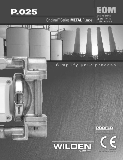
¼" Pro-Flo metal pump (P0.25) - Process Pumps
¼" Pro-Flo metal pump (P0.25) - Process Pumps
¼" Pro-Flo metal pump (P0.25) - Process Pumps
- No tags were found...

You also want an ePaper? Increase the reach of your titles
YUMPU automatically turns print PDFs into web optimized ePapers that Google loves.
Section 4DIMENSIONAL DRAWINGSP.025 Metal6.35 mm (1/4")(FNPT) AIR INLET6.35 mm (1/4")BSP (FNPT) LIQUID DISCHARGEAIR EXHAUSTCDBEA6.35 mm (1/4")BSP (FNPT) LIQUID INLETFGHJLKDIMENSIONSITEM METRIC (mm) STANDARD (inch)A 165 6.5B 84 3.3C 148 5.8D 136 5.3E 13 .5F 114 4.5G 92 3.6H 60 2.4J 6 .3K 70 2.8L 47 1.8WILDEN PUMP & ENGINEERING CO. 4 WIL-10080-E-02
Section 5APERFORMANCEP.025 METALRUBBER-FITTEDHeight ......................................148 mm (5.8")Width ....................................165.1 mm (6.5")Depth ...................................114.3 mm (4.5")Ship Weight ................. Aluminum 1.8 kg (4 lbs.)Stainless Steel 4.0 kg (8.9 lbs.)Hastelloy ® 4.3 kg (9.5 lbs.)Air Inlet ....................................... 3.2 mm ( 1 ⁄8")Inlet .............................................6.4 mm ( 1 ⁄4")Outlet ..........................................6.4 mm ( 1 ⁄4")Suction Lift ..........................3.3 m Dry (10'8")9.3 m Wet (30'6")Displacement perStroke ...........................0.02 l (0.005 gal.) 1Max. <strong>Flo</strong>w Rate ..................18.91 lpm (5 gpm)Max. Size Solids ......................... .4 mm ( 1 ⁄64")1Displacement per stroke was calculated at 70 psig(4.8 Bar) air inlet pressure against a 30 psig (2 Bar)head pressure.Example: To <strong>pump</strong> 7.6 lpm (2 gpm) againsta discharge pressure head of 40 psig (2.8Bar) requires 4.1 Bar (61 psig) and 1.2 Nm 3 /h(.7 scfm) air consumption. (See dot on chart.)Caution: Do not exceed 8.6 Bar (125psig) supply pressure.Discharge PressureAIR CONSUMPTION(SCFM)[N3 /h](3) [5.1](5) [8.5]<strong>Flo</strong>w rates indicated on chart were determined by <strong>pump</strong>ing water.For optimum life and performance, <strong>pump</strong>s should be specified so that daily operation parameterswill fall in the center of the <strong>pump</strong> performance curve.P.025 METALTPE-FITTEDHeight ......................................148 mm (5.8")Width .......................................165 mm (6.5")Depth ......................................114 mm (4.5")Ship Weight ................. Aluminum 1.8 kg (4 lbs.)Stainless Steel 4.0 kg (8.9 lbs.)Hastelloy ® 4.3 kg (9.5 lbs.)Air Inlet ....................................... 3.2 mm ( 1 ⁄8")Inlet .............................................6.4 mm ( 1 ⁄4")Outlet ..........................................6.4 mm ( 1 ⁄4")Suction Lift ..........................4.1 m Dry (13'6")9.3 m Wet (30'6")Displacement perStroke ...........................0.02 l (0.005 gal.) 1Max. <strong>Flo</strong>w Rate ....................18.9 lpm (5 gpm)Max. Size Solids ......................... .4 mm ( 1 ⁄64")1Displacement per stroke was calculated at 70 psig(4.8 Bar) air inlet pressure against a 30 psig (2 Bar)head pressure.Example: To <strong>pump</strong> 7.6 lpm (2 gpm) againsta discharge pressure head of 40 psig (2.8 Bar)requires 4.0 Bar (59 psig) and 1.1 Nm 3 /h (.7scfm) air consumption. (See dot on chart.)Caution: Do not exceed 8.6 Bar(125 psig) air supply pressure.Discharge Pressure<strong>Flo</strong>w rates indicated on chart were determined by <strong>pump</strong>ing water.For optimum life and performance, <strong>pump</strong>s should be specified so that daily operation parameterswill fall in the center of the <strong>pump</strong> performance curve.WIL-10080-E-02 5 WILDEN PUMP & ENGINEERING CO.
Section 6SUGGESTED INSTALLATIONThe <strong>Pro</strong>-<strong>Flo</strong> model P.025 has a 6.4 mm ( 1 ⁄4") inlet and 6.4mm ( 1 ⁄4") outlet and is designed for flows to 18.9 l/m (5 gpm).The P.025 <strong>metal</strong> <strong>pump</strong> is manufactured with wetted parts ofaluminum Hastelloy ® and stainless steel. The center sectionof the P.025 <strong>metal</strong> is constructed of virgin acetal or polypropylene.A variety of diaphragms and O-rings are available tosatisfy temperature, chemical compatibility, abrasion and flexconcerns.The suction pipe size should be at least 6.4 mm ( 1 ⁄4") diameteror larger if highly viscous material is being <strong>pump</strong>ed. Thesuction hose must be non-collapsible, reinforced type as theP.025 is capable of pulling a high vacuum. Discharge pipingshould be at least 6.35 mm ( 1 ⁄4"); larger diameter can beused to reduce friction losses. It is critical that all fittings andconnections are airtight or a reduction or loss of <strong>pump</strong> suctioncapability will result.INSTALLATION: Months of careful planning, study, and selectionefforts can result in unsatisfactory <strong>pump</strong> performance ifinstallation details are left to chance.Premature failure and long term dissatisfaction can beavoided if reasonable care is exercised throughout the installationprocess.LOCATION: Noise, safety, and other logistical factors usuallydictate that “utility" equipment be situated away from theproduction floor. Multiple installations with conflicting requirementscan result in congestion of utility areas, leaving fewchoices for siting of additional <strong>pump</strong>s.Within the framework of these and other existing conditions,every <strong>pump</strong> should be located in such a way that four keyfactors are balanced against each other to maximum advantage.1. ACCESS: First of all, the location should be accessible.If it's easy to reach the <strong>pump</strong>, maintenance personnel willhave an easier time carrying out routine inspections andadjustments. Should major repairs become necessary, easeof access can play a key role in speeding the repair processand reducing total downtime.2. AIR SUPPLY: Every <strong>pump</strong> location should have an airline large enough to supply the volume of air necessary toachieve the desired <strong>pump</strong>ing rate (see <strong>pump</strong> performancechart). Use air pressure up to a maximum of 8.6 Bar (125 psi)depending on <strong>pump</strong>ing requirements.Sound levels are reduced below OSHA specifications usingthe standard Wilden muffler element.3. ELEVATION: Selecting a site that is well within the <strong>pump</strong>'sdynamic lift capability will assure that loss-of-prime troubles willbe eliminated. In addition, <strong>pump</strong> efficiency can be adverselyaffected if proper attention is not given to site location.4. PIPING: Final determination of the <strong>pump</strong> site should not bemade until the piping problems of each possible location havebeen evaluated. The impact of current and future installationsshould be considered ahead of time to make sure that inadvertentrestrictions are not created for any remaining sites.The best choice possible will be a site involving the shortestand straightest hook-up of suction and discharge piping.Unnecessary elbows, bends, and fittings should be avoided.Pipe sizes should be selected so as to keep friction losseswithin practical limits. All piping should be supported independentlyof the <strong>pump</strong>. In addition, the piping should be alignedso as to avoid placing stresses on the <strong>pump</strong> fittings.Flexible hose can be installed to aid in absorbing the forcescreated by the natural reciprocating action of the <strong>pump</strong>. If the<strong>pump</strong> is to be bolted down to a solid location, a mountingpad placed between the <strong>pump</strong> and the foundation will assistin minimizing <strong>pump</strong> vibration. Flexible connections betweenthe <strong>pump</strong> and rigid piping will also assist in minimizing <strong>pump</strong>vibration. If quick-closing valves are installed at any point inthe discharge system, or if pulsation within a system becomesa problem, a Wilden SD 1 ⁄2 Equalizer surge dampener shouldbe installed to protect the <strong>pump</strong>, piping and gauges fromsurges and water hammer.When <strong>pump</strong>s are installed in applications involving floodedsuction or suction head pressures, a gate valve should beinstalled in the suction line to permit closing of the line for<strong>pump</strong> service.The P.025 cannot be used in submersible applications.If the <strong>pump</strong> is to be used in a self-priming application, besure that all connections are airtight and that the suction lift iswithin the model's ability. Note: Materials of construction andelastomer material have an effect on suction lift parameters.Please consult Wilden distributors for specifics.<strong>Pumps</strong> in service with a positive suction head are most efficientwhen inlet pressure is limited to .4–.7 Bar (7-10 psig).Premature diaphragm failure may occur if positive suction is.7 Bar (10 psi) and higher.THE MODEL P.025 WILL PASS .4 MM ( 1 ⁄64") SOLIDS.WHENEVER THE POSSIBILITY EXISTS THAT LARGERSOLID OBJECTS MAY BE SUCKED INTO THE PUMP, ASTRAINER SHOULD BE USED ON THE SUCTION LINE.CAUTION: DO NOT EXCEED 8.6 BAR (125 PSIG) AIRSUPPLY PRESSURE.BLOW OUT AIR LINE FOR 10 TO 20 SECONDS BEFOREATTACHING TO PUMP TO MAKE SURE ALL PIPE LINEDEBRIS IS CLEAR.The <strong>Pro</strong>-<strong>Flo</strong> <strong>pump</strong> is not submersible.WIL-10080-E-02 7 WILDEN PUMP & ENGINEERING CO.
SUGGESTED INSTALLATIONAIR-OPERATED PUMPS: To stop the <strong>pump</strong> from operating in anemergency situation, simply close the “shut-off" valve (user supplied)installed in the air supply line. A properly functioning valve will stop theair supply to the <strong>pump</strong>, therefore stopping output. This “shut-off"valve should be located far enough away from the <strong>pump</strong>ing equipmentsuch that it can be reached safely in an emergency situation.NOTE: In the event of a power failure, the shutoff valve should be closed, if the restarting of the <strong>pump</strong> is not desirable once poweris regained.NOTE: Wilden 1/4" <strong>metal</strong> <strong>pump</strong>s come standard side ported with 2 NPT or BSP pipe plugs for side inlet and discharge porting. Center,top and bottom inlet and discharge porting are optional. Simply drill flat areas provided with a 7/16" drill bit for NPT or 11mm drill bit forBSP and tap with an NTP or BSP tap as needed.NOTE: Wilden offers drum <strong>pump</strong> kits for the Metal P.025/A.025 <strong>pump</strong> (bung base and pick-up tube) for convenient drum <strong>pump</strong>ing(P/N 50-9290-20/23/55).NOTE: This <strong>pump</strong> can be mounted from the underside of a flat surface providing you more flexibility in tight areas/systems.CAUTION: Pump performance will be seriously hampered if <strong>pump</strong> is installed upside down.WILDEN PUMP & ENGINEERING CO. 8 WIL-10080-E-02
SUGGESTED OPERATION & MAINTENANCEFor best results, the <strong>pump</strong>s should use an air filter and regulator.The use of an air filter before the <strong>pump</strong> will insure thatthe majority of any pipeline contaminants will be eliminated.The P.025 is permanently lubricated, and does not requirein-line lubrication. Additional lubrication will not damage the<strong>pump</strong>, however if the <strong>pump</strong> is heavily lubricated by an externalsource, the <strong>pump</strong>'s internal lubrication may be washed away.If the <strong>pump</strong> is then moved to a non-lubricated location, it mayneed to be disassembled and re-lubricated as described in theASSEMBLY/DISASSEMBLY INSTRUCTIONS.Pump discharge rate can be controlled by limiting the volumeand/or pressure of the air supply to the <strong>pump</strong> (preferredmethod). A regulator is used to regulate air pressure. A needlevalve is used to regulate air volume. Pump discharge rate canalso be controlled by throttling the <strong>pump</strong> discharge by installinga valve in the discharge line of the <strong>pump</strong>. This is usefulwhen the need exists to control the <strong>pump</strong> from a remote location.When the <strong>pump</strong> discharge pressure equals or exceedsthe air supply pressure, the <strong>pump</strong> will stop; no bypass orpressure relief valve is needed, and <strong>pump</strong> damage will notoccur. When operation is controlled by a solenoid valve inthe air line, two-way or three-way valves may be used. Pumpingvolume can be set by counting the number of strokesper minute.INSPECTIONS: Periodic inspections have been found tooffer the best means for preventing unscheduled <strong>pump</strong> downtime.Personnel familiar with the <strong>pump</strong>'s construction andservice should be informed of any abnormalities that aredetected during operation.RECORDS: When service is required, a record should bemade of all necessary repairs and replacements. Over a periodof time, such records can become a valuable tool for predictingand preventing future maintenance problems and unscheduleddowntime. In addition, accurate records make it possible toidentify <strong>pump</strong>s that are poorly suited to their applications.TROUBLESHOOTINGPump will not run or runs slowly.1. Ensure that the air inlet pressure is at least 5 psig abovestartup pressure and that the differential pressure (thedifference between inlet and discharge pressures) is notless than 10 psig.2. Check air inlet filter for debris (see recommendedinstallation).3. Check for extreme air leakage which would indicate wornout seals/bores.4. Disassemble <strong>pump</strong> and check for obstructions in the airpassageways or objects which would obstruct the movementof internal parts.5. Check for sticking ball check valves. If material being<strong>pump</strong>ed is not compatible with <strong>pump</strong> elastomers, swellingmay occur. Replace ball check valves and seals withproper elastomers. Also, as the check valve balls wearout, they become smaller and can become stuck in theseats. In this case, replace balls and seats.Pump runs but little or no product flows.1. Check for <strong>pump</strong> cavitation; slow <strong>pump</strong> speed down tomatch thickness of material being <strong>pump</strong>ed.2. Verify that vacuum required to lift liquid is not greater thanthe vapor pressure of the material being <strong>pump</strong>ed (cavitation).3. Check for sticking ball check valves. If material being<strong>pump</strong>ed is not compatible with <strong>pump</strong> elastomers, swellingmay occur. Replace ball check valves and seals withproper elastomers. Also, as the check valve balls wearout, they become smaller and can become stuck in theseats. In this case, replace balls and seats.4. Ensure that all suction connections are tight.Pump air valve freezes.1. Check for excessive moisture in compressed air. Eitherinstall a dryer or hot air generator for compressedair. Alternatively, a coalescing filter may be used toremove the water from the compressed air in someapplications.Air bubbles in <strong>pump</strong> discharge.1. Check for ruptured diaphragm.2. Check tightness of outer pistons.3. Check tightness of clamp bands and integrity of O-ringsand seals, especially at intake manifold.4. Ensure pipe connections are airtight.<strong>Pro</strong>duct comes out air exhaust.1. Check for diaphragm rupture.2. Check tightness of pistons to shaft.Pump rattles.1. See E9 Troubleshooting Guide.2. Create false discharge head or suction lift.WIL-10080-E-02 9 WILDEN PUMP & ENGINEERING CO.
Section 7PUMP DISASSEMBLYCAUTION: Before any maintenance or repair is attempted, thecompressed air line to the <strong>pump</strong> should be disconnected and allair pressure allowed to bleed from <strong>pump</strong>. Disconnect all intake,discharge, and air lines. Drain the <strong>pump</strong> by turning it upsidedown and allowing any fluid to flow into a suitable container.Wetted flushing of parts may be required prior to handling.The Wilden model P.025 (Figure 1) is an air-operated, doublediaphragm<strong>pump</strong> with all wetted parts of aluminum, stainlesssteel or Hastelloy ® . The single-piece center section, consistingof center block and air chambers, is molded from acetal orpolypropylene. The air valve is manufactured of acetal or polypropylene.All O-rings used in the <strong>pump</strong> are of special materialsand should only be replaced with factory-supplied parts.To expedite parts ordering, please find an exploded view of theP.025 model at the back of this manual.PLEASE read all directions before starting disassembly.TOOLS REQUIRED:3⁄16" Hex Key (Allen wrench)7⁄16" Wrench or Socket for Rubber-Fitted5⁄16" Wrench or Socket3⁄8" WrenchO-ring Pick3⁄16" Rod or EquivalentDISASSEMBLY:Figure 1Step 1.Before actual disassembly is started, turn <strong>pump</strong> upsidedown and drain all liquid trapped in the <strong>pump</strong> into a suitablecontainer. Be sure to use proper caution if liquid is corrosiveor toxic. Mark each liquid chamber to its respective air chamberfor easy alignment during reassembly. (Figure 1)Step 2. Figure 2Using a 3 ⁄16" allen wrench, loosen the four manifold bolts.(Figure 2) Remove the top and bottom manifolds.Step 3. Figure 3Inspect both manifolds, manifold O-rings, and valve balls.(Figure 3) If swelling, cracking or other damage is apparent,these parts must be replaced with genuine Wilden parts.WILDEN PUMP & ENGINEERING CO. 10 WIL-10080-E-02
PUMP DISASSEMBLYStep 4 Figure 4NOTE: Top valve seats of aluminum P.025 <strong>pump</strong>s are castin the liquid chamber.Step 4a.Figure 4aTo remove top and bottom valve seats, on stainless steelor Hastelloy ® <strong>pump</strong>s, use an O-ring pick and pull seats outfrom top to bottom or use 3 ⁄16" rod and push seats through.(Figure 4a)Step 5. Figure 5Remove bottom manifold. Inspect balls and seats for abrasion.Inspect seat O-rings and manifold O-rings for swelling,cracking, or other damage. These parts should bereplaced if damage is observed. (Figure 5)Step 6. Figure 6Loosen clamp band with 5 ⁄16" socket and 3 ⁄8" wrench.(Figure 6) Remove screw and nut.NOTE: Aluminum <strong>pump</strong>s employ 2 O-rings per valve seat.WIL-10080-E-02 11 WILDEN PUMP & ENGINEERING CO.
PUMP DISASSEMBLYStep 7. Figure 7After clamp bands are removed, pull chambers away fromcenter section (Figure 7).Step 8. Figure 8Remove diaphragm by turning in counter-clockwise direction.(Figure 8)NOTE: Teflon ® -fitted <strong>pump</strong>s (shown) utilize a Neoprene backupO-ring. Rubber or TPE-fitted <strong>pump</strong>s do not.(See figure 10 for details.)Step 9. Figure 9Pull off Teflon ® PTFE diaphragm and O-ring. (Figure 9) Twistoff remaining diaphragm in counter-clockwise direction.Inspection of diaphragms and O-rings is now possible.Step 10. Figure 10For Rubber / TPE fitted <strong>pump</strong>s, remove the outer pistonwith 7 /16" wrench. You are now able to remove the completeassembly. Inspection of diaphragms and outer pistons is nowpossible.WILDEN PUMP & ENGINEERING CO. 12 WIL-10080-E-02
DISASSEMBLY, CLEANING, & INSPECTIONAIR VALVE DISASSEMBLY:CAUTION: Before any maintenance or repair is attempted,the compressed air line to the <strong>pump</strong> should be disconnectedand all air pressure allowed to bleed from the<strong>pump</strong>. Disconnect all intake, discharge, and air lines.Drain the <strong>pump</strong> by turning it upside down and allowingany fluid to flow into a suitable container. Be aware ofhazardous effects of contact with your process fluid.The Wilden Metal P.025 utilizes a revolutionary <strong>Pro</strong>-<strong>Flo</strong>air distribution system. A 3.2 mm ( 1 ⁄8") air inlet connects theair supply to the center section. <strong>Pro</strong>prietary composite sealsreduce the coefficient of friction and allow the P.025 to runlube-free. Constructed of acetal or polypropylene, the <strong>Pro</strong>-<strong>Flo</strong> air distribution system is designed to perform in on/off,non-freezing, non-stalling, tough duty applications.TOOLS REQUIRED:5⁄32" Hex Head WrenchO-Ring PickStep 1 Figure 1Remove air valve screws from center section with a 5 ⁄32" hexkey (Allen wrench). (Figure 1)Step 2. Figure 2Take care while removing air valve not to damage gasket.(Figure 2)NOTE: Air valve has molded-in alignment pins for properpositioning during assembly.Step 3. Figure 3Remove air valve end cap by simply pulling it away from airvalve body (no tools required). (Figure 3) Inspect O-ring andreplace as needed with genuine Wilden parts.WIL-10080-E-02 13 WILDEN PUMP & ENGINEERING CO.
DISASSEMBLY, CLEANING, & INSPECTIONStep 4. Figure 4The air valve spool can now be removed. A 10-24 UNC(Unified National Coarse thread) screw can be screwed intothe threaded hole located in the center of the spool. Gripthe screw with pliers and remove. If a 10-24 UNC screw isnot available, the spool can be tapped out against a woodblock or blown out with compressed air. Upon reassembly,lubricate air valve with NLGI grade 2 molybdenum disulfidebased grease or equivalent. (Figure 4)Step 5. Figure 5Remove the porous polyethylene muffler element by slidingit toward the end cap opening. (Figure 5) The elementcan be cleaned by soaking it in a cleaning solution (nosolvents). If the muffler restricts the air exhaust, replacemuffler element.Step 6. Figure 6Remove pilot spool retaining ring with an O-ring pick.(Figure 6)Step 7. Figure 7Push pilot spool through center section and remove. Inspectseals for integrity and spool for damage. Replace pilot spoolassembly if necessary. Upon reassembly of spool, apply afilm of NLGI grade 2 molybdenum disulfide based grease orequivalent (P/N 99-8310-99). (Figure 7)WILDEN PUMP & ENGINEERING CO. 14 WIL-10080-E-02
REASSEMBLYUpon performing applicable maintenance to the air distributionsystem, the <strong>pump</strong> can now be reassembled. Please referto the disassembly instructions for photos and parts placement.To reassemble <strong>pump</strong>, follow the disassembly instructionsin reverse order. The air distribution system needs to beassembled first, then the diaphragms, and finally the wettedparts. Please find applicable torque specifications in thissection.Rubber/TPE diaphragm configuration Figure 1 Teflon ® diaphragm configuration Figure 2There are two types of diaphragm configurations available forthe P.025: 1) Rubber or TPE diaphragm, and 2) Teflon ®primary diaphragm with back-up O-ring. Observe the "ThisSide Out" marking on the convex side of the diaphragm.Install the disc spring, inner piston, diaphragm, back-upO-ring (Teflon ® -fitted models only), and the outer piston tomain shaft assembly. (NOTE: Teflon ® Fitted <strong>pump</strong>s employ anintegral piston diaphragm). Add a small amount of Loctite 242to the bore of the main shaft. Set up time is 20 minutes.Tighten outer piston to torque value found below.Lubricate the main shaft assembly with NLGI grade 2 molybdenumdisulfide based grease or equivalent and insert throughmain shaft bore in center section. Assemble the other sideand torque to proper value as listed below. Please review thephotos above for proper alignment.TORQUE SPECIFICATIONS FOR MODEL P.025 PUMPSDescription of PartAir ValveOuter Piston, Rubber and TPE DiaphragmsClamp BandManifold BoltMaximum Torque[2.3 m-N] 20 in.-lbs.[4.6 m-N] 40 in.-lbs.[2.3 m-N] 20 in.-lbs.[5.6 m-N] 50 in.-lbs.• Apply a small amount of Loctite 242 to the internal threads ofthe shaft prior to reassembly.WIL-10080-E-02 15 WILDEN PUMP & ENGINEERING CO.
Section 8EXPLODED VIEW & PARTS LISTINGP.025 METAL RUBBER/TPE-FITTED EXPLODED VIEWStainless Steel &Hastelloy ® seatingconfiguration23WILDEN PUMP & ENGINEERING CO. 16 WIL-10080-E-02
EXPLODED VIEW & PARTS LISTINGP.025 METAL RUBBER/TPE-FITTED PART LISTINGItem #Qty.perPumpP.025/APPPALUMINUMP/NP.025/ALLLALUMINUMP/NP.025/SPPPSTAINLESSSTEELP/NP.025/SLLLSTAINLESSSTEELP/NP.025/HPPPHASTELLOYP/NP.025/HLLLHASTELLOYP/N1 <strong>Pro</strong>-<strong>Flo</strong> Air Valve Assembly 1 1 00-2000-20-700 00-2000-13-700 00-2000-20-700 00-2000-13-700 00-2000-20-700 00-2000-13-7002 <strong>Pro</strong>-<strong>Flo</strong> Air Valve End Cap 1 00-2300-20-700 00-2300-13-700 00-2300-20-700 00-2300-13-700 00-2300-20-700 00-2300-13-7003 End Cap O-Ring 1 00-2390-52-700 00-2390-52-700 00-2390-52-700 000-2390-52-700 00-2390-52-700 00-2390-52-7004 Muffler Element 1 00-3240-26-700 00-3240-26-700 00-3240-26-700 00-3240-26-700 00-3240-26-700 00-3240-26-7005 Air Valve Bolt 4 00-6000-03-700 00-6000-03-700 00-6000-03-700 00-6000-03-700 00-6000-03-700 00-6000-03-7006 Air Valve Gasket 1 00-2600-52-700 00-2600-52-700 00-2600-52-700 00-2600-52-700 00-2600-52-700 00-2600-52-7007 Air Valve Nut 4 01-6400-03 01-6400-03 01-6400-03 01-6400-03 01-6400-03 01-6400-038 <strong>Pro</strong>-<strong>Flo</strong> Center Section 1 00-3150-20-700 00-3150-13-700 00-3150-20-700 00-3150-13-700 00-3150-20-700 00-3150-13-7009 Pilot Spool Assembly 1 00-3850-99-700 00-3850-99-700 00-3850-99-700 00-3850-99-700 00-3850-99-700 00-3850-99-70010 Pilot Spool Retaining Ring 1 00-2650-03-700 00-2650-03-700 00-2650-03-700 00-2650-03-700 00-2650-03-700 00-2650-03-70011 Main Shaft Assembly 1 00-3800-99-700 00-3800-99-700 00-3800-99-700 00-3800-99-700 00-3800-99-700 00-3800-99-70012 Disc Spring 2 00-6800-08 00-6800-08 00-6800-08 00-6800-08 00-6800-08 00-6800-0813 Inner Piston for Rubber/TPE 2 00-3700-20-700 00-3700-13-700 00-3700-20-700 00-3700-13-700 00-3700-20-700 00-3700-13-70014 Outer Piston 2 00-4570-08 00-4570-08 00-4570-03 00-4570-03 00-4570-04 00-4570-0415 Liquid Chamber 2 00-5000-01 00-5000-01 00-5000-03 00-5000-03 00-5000-04 00-5000-0416 Manifold (NPT) 2 00-5050-01 00-5050-01 00-5050-03 00-5050-03 00-5050-04 00-5050-04Manifold (BSP) 2 00-5051-01 00-5051-01 00-5051-03 00-5051-03 00-5051-04 00-5051-0417 Pipe Plug (NPT) 2 00-7010-08 00-7010-08 00-7010-03 00-7010-03 00-7010-04 00-7010-04Pipe Plug (BSP) 2 00-7011-08 00-7011-08 00-7011-03 00-7011-03 00-7011-04 00-7011-0418 Manifold Bolt 4 01-6000-03 01-6000-03 01-6000-03 01-6000-03 01-6000-03 01-6000-0319 Square Nut 4 00-6505-03 00-6505-03 00-6505-03 00-6505-03 00-6505-03 00-6505-0320 Manifold O-ring* 4 * * * * * *21 Valve Seat O-Ring* 4 * * * * * *22 Valve Seat 4 00-1120-01** 00-1120-01** 00-1120-03 00-1120-03 00-1120-04 00-1120-0423 Valve Ball 4 00-1080-55 00-1080-55 00-1080-55 00-1080-55 00-1080-55 00-1080-5524 Diaphragm* 2 * * * * * *25 Clamp Band Assembly 2 00-7300-03 00-7300-03 00-7300-03 00-7300-03 00-7300-03 00-7300-0326 —Clamp Band Bolt 4 01-6100-03 01-6100-03 01-6100-03 01-6100-03 01-6100-03 01-6100-0327 —Clamp Band Nut 4 01-6400-03 01-6400-03 01-6400-03 01-6400-03 01-6400-03 01-6400-03*Refer to Elastomer Options in Section 10.1Air Valve Assembly includes items 2, 3 and 4.**Quantity per <strong>pump</strong> is 2All boldface items are primary wear parts.WIL-10080-E-02 17 WILDEN PUMP & ENGINEERING CO.
Section 8EXPLODED VIEW & PARTS LISTINGP.025 METAL PTFE-FITTED EXPLODED VIEWStainless Steel &Hastelloy ® seatingconfigurationWILDEN PUMP & ENGINEERING CO. 18 WIL-10080-E-02
EXPLODED VIEW & PARTS LISTINGP.025 METAL PTFE-FITTED PART LISTINGItem #Description*Refer to Elastomer Options in Section 10.1Air Valve Assembly includes items 1, 2 and 3.**Quantity per <strong>pump</strong> is 2All boldface items are primary wear parts.Qty.perPumpP.025/APPPALUMINUMP/NP.025/ALLLALUMINUMP/NP.025/SPPPSTAINLESSSTEELP/NP.025/SLLLSTAINLESSSTEELP/NP.025/HPPPHASTELLOYP/NP.025/HLLLHASTELLOYP/N1 <strong>Pro</strong>-<strong>Flo</strong> Air Valve Assembly 1 1 00-2000-20-700 00-2000-13-700 00-2000-20-700 00-2000-13-700 00-2000-20-700 00-2000-13-7002 <strong>Pro</strong>-<strong>Flo</strong> Air Valve End Cap 1 00-2300-20-700 00-2300-13-700 00-2300-20-700 00-2300-13-700 00-2300-20-700 00-2300-13-7003 End Cap O-Ring 1 00-3240-26-700 00-3240-26-700 00-3240-26-700 00-2390-52-700 00-2390-52-700 00-2390-52-7004 Muffler Element 1 00-2340-26-700 00-2340-26-700 00-2340-26-700 00-3240-26-700 00-3240-26-700 00-3240-26-7005 Air Valve Bolt 4 00-6000-03-700 00-6000-03-700 00-6000-03-700 00-6000-03-700 00-6000-03-700 00-6000-03-7006 Air Valve Gasket 1 00-2600-52-700 00-2600-52-700 00-2600-52-700 00-2600-52-700 00-2600-52-700 00-2600-52-7007 Air Valve Nut 4 01-6400-03 01-6400-03 01-6400-03 01-6400-03 01-6400-03 01-6400-038 <strong>Pro</strong>-<strong>Flo</strong> Center Section 1 00-3150-20-700 00-3150-13-700 00-3150-20-700 00-3150-13-700 00-3150-20-700 00-3150-13-7009 Pilot Spool Assembly 1 00-3850-99-700 00-3850-99-700 00-3850-99-700 00-3850-99-700 00-3850-99-700 00-3850-99-70010 Pilot Spool Retaining Ring 1 00-2650-03-700 00-2650-03-700 00-2650-03-700 00-2650-03-700 00-2650-03-700 00-2650-03-70011 Main Shaft Assembly 1 00-3800-99-700 00-3800-99-700 00-3800-99-700 00-3800-99-700 00-3800-99-700 00-3800-99-70012 Inner Piston for PTFE Fitted 2 00-3750-20-700 00-3750-13-700 00-3750-20-700 00-3750-13-700 00-3750-20-700 00-3750-13-70013 Back-Up O-Ring 2 00-1070-51 00-1070-51 00-1070-51 00-1070-51 00-1070-51 00-1070-5114 Liquid Chamber 2 00-5000-01 00-5000-01 00-5000-03 00-5000-03 00-5000-04 00-5000-0415 Manifold (NPT) 2 00-5050-01 00-5050-01 00-5050-03 00-5050-03 00-5050-04 00-5050-04Manifold (BSP) 2 00-5051-01 00-5051-01 00-5051-03 00-5051-03 00-5051-04 00-5051-0416 Pipe Plug (NPT) 2 00-7010-08 00-7010-08 00-7010-03 00-7010-03 00-7010-04 00-7010-04Pipe Plug (BSP) 2 00-7011-08 00-7011-08 00-7011-03 00-7011-03 00-7011-04 00-7011-0417 Manifold Bolt 4 01-6000-03 01-6000-03 01-6000-03 01-6000-03 01-6000-03 01-6000-0318 Square Nut 4 00-6505-03 00-6505-03 00-6505-03 00-6505-03 00-6505-03 00-6505-0319 Manifold O-ring* 4 * * * * * *20 Valve Seat O-Ring* 4 * * * * * *21 Valve Seat 4 00-1120-01** 00-1120-01** 00-1120-03 00-1120-03 00-1120-04 00-1120-0422 Valve Ball 4 00-1080-55 00-1080-55 00-1080-55 00-1080-55 00-1080-55 00-1080-5523 Diaphragm 2 00-1030-55 00-1030-55 00-1030-55 00-1030-55 00-1030-55 00-1030-5524 Clamp Band Assembly 2 00-7300-03 00-7300-03 00-7300-03 00-7300-03 00-7300-03 00-7300-0325 —Clamp Band Bolt 4 01-6100-03 01-6100-03 01-6100-03 01-6100-03 01-6100-03 01-6100-0326 —Clamp Band Nut 4 01-6400-03 01-6400-03 01-6400-03 01-6400-03 01-6400-03 01-6400-03WIL-10080-E-02 19 WILDEN PUMP & ENGINEERING CO.
Section 9ELASTOMER OPTIONSModel P.025 Metal <strong>Pumps</strong>MaterialValve SeatO-RingManifoldO-RingDiaphragmBack-UpDiaphragm O-RingValve BallWil-Flex — — 00-1010-58 — N/ABuna-N 00-1200-52 04-2390-52 00-1010-52 — N/AViton ® — — — — N/ATeflon ® PTFE 00-1200-55 2 00-1370-55 00-1030-55 — 00-1080-55Stainless Steel — — — — N/ATeflon ® -Encapsulated00-1200-60 1 — — — N/AViton ®Neoprene — — — 00-1070-51 N/A1. Used on SS/Hastelloy ® only2. Used on Aluminum onlyWILDEN PUMP & ENGINEERING CO. 20 WIL-10080-E-02
WARRANTYEach and every product manufactured by Wilden Pump and Engineering, LLC is built to meet the higheststandards of quality. Every <strong>pump</strong> is functionally tested to insure integrity of operation.Wilden Pump and Engineering, LLC warrants that <strong>pump</strong>s, accessories and parts manufactured or supplied byit to be free from defects in material and workmanship for a period of five (5) years from date of installation orsix (6) years from date of manufacture, whichever comes first. Failure due to normal wear, misapplication, orabuse is, of course, excluded from this warranty.Since the use of Wilden <strong>pump</strong>s and parts is beyond our control, we cannot guarantee the suitability of any <strong>pump</strong>or part for a particular application and Wilden Pump and Engineering, LLC shall not be liable for any consequentialdamage or expense arising from the use or misuse of its products on any application. Responsibility is limitedsolely to replacement or repair of defective Wilden <strong>pump</strong>s and parts.All decisions as to the cause of failure are the sole determination of Wilden Pump and Engineering, LLC.Prior approval must be obtained from Wilden for return of any items for warranty consideration and must beaccompanied by the appropriate MSDS for the product(s) involved. A Return Goods Tag, obtained from anauthorized Wilden distributor, must be included with the items which must be shipped freight prepaid.The foregoing warranty is exclusive and in lieu of all other warranties expressed or implied (whether written or oral)including all implied warranties of merchantability and fitness for any particular purpose. No distributor or otherperson is authorized to assume any liability or obligation for Wilden Pump and Engineering, LLC other than expresslyprovided herein.PLEASE PRINT OR TYPE AND FAX TO WILDENPUMP INFORMATIONItem # Serial #Company Where PurchasedYOUR INFORMATIONCompany NameIndustryNameTitleStreet AddressCity State Postal Code CountryTelephone Fax E-mail Web AddressNumber of <strong>pump</strong>s in facility?Number of Wilden <strong>pump</strong>s?Types of <strong>pump</strong>s in facility (check all that apply): Diaphragm Centrifugal Gear Submersible LobeOtherMedia being <strong>pump</strong>ed?How did you hear of Wilden Pump? Trade Journal Trade Show Internet/E-mail DistributorOtherONCE COMPLETE, FAX TO (909) 783-3440NOTE: WARRANTY VOID IF PAGE IS NOT FAXED TO WILDENWILDEN PUMP & ENGINEERING, LLC