1" Pro-Flo advanced plastic pump (P200) - Process Pumps
1" Pro-Flo advanced plastic pump (P200) - Process Pumps
1" Pro-Flo advanced plastic pump (P200) - Process Pumps
- No tags were found...

Create successful ePaper yourself
Turn your PDF publications into a flip-book with our unique Google optimized e-Paper software.
<strong>P200</strong>Advanced Series PLASTIC <strong>Pumps</strong>EngineeringOperation &MaintenanceAdvance your processWIL-11070-E-08REPLACES WIL-11070-E-07
TABLE OF CONTENTSSECTION 1 — CAUTIONS ............................................................................................ 1SECTION 2 — PUMP DESIGNATION SYSTEM ......................................... 2SECTION 3 — HOW IT WORKS (PUMP & AIR SYSTEMS) ............ 3SECTION 4 — DIMENSIONAL DRAWING ....................................................... 4SECTION 5 — PERFORMANCE CURVESA. <strong>P200</strong> ADVANCED PLASTIC Rubber-Fitted .................................................................... 5B. <strong>P200</strong> ADVANCED PLASTIC TPE-Fitted ......................................................................... 5C. <strong>P200</strong> ADVANCED PLASTIC PTFE-Fitted ....................................................................... 6SECTION 6 — SUCTION LIFT CURVES & DATA .................................... 6SECTION 7 — INSTALLATION AND OPERATIONA. Installation .......................................................................................................................... 7B. Operation & Maintenance .................................................................................................. 8C. Troubleshooting .................................................................................................................. 9SECTION 8 — DIRECTIONS FOR DISASSEMBLY/REASSEMBLYA. <strong>P200</strong> ADVANCED PLASTIC Wetted Path — Tools Required ................................................. 10B. <strong>Pro</strong>-<strong>Flo</strong> ® Air Valve/Center Block — Disassembly, Cleaning, Inspection .......................... 13C. Reassembly Hints & Tips, Torque Specs. ......................................................................... 15SECTION 9 — EXPLODED VIEW/PARTS LISTINGA. <strong>P200</strong> ADVANCED PLASTIC Rubber/TPE-Fitted ............................................................ 16B. <strong>P200</strong> ADVANCED PLASTIC PTFE-Fitted ....................................................................... 18SECTION 10 — ELASTOMER OPTIONS ......................................................... 20PAGE #NONUSEClass I & II OzoneU.S. Clean Air ActAmendments of 1990Depleting Substances
SECTION 1CAUTIONS – READ FIRST!TEMPERATURE LIMITS*Wetted PathPolypropylene (PP) 0°C to 79.4°C 32 °F to 175°FPolyvinylidene fluoride (PVDF)-12.2°C to 107.2°C 10 °F to 225°FPFA -28.9°C to 87.8°C -20 °F to 190°FElastomersNeoprene -17.8°C to 93.3°C 0 °F to 200°FBuna-N -12.2°C to 82.2°C 10 °F to 180°FEPDM -51.1°C to 137.8°C -60 °F to 280°FViton ® -40°C to 176.7°C -40 °F to 350°FWil-Flex -40°C to 107.2°C -40 °F to 225°FPolyurethane 12.2°C to 65.6°C 10 °F to 150°FTetra-Flex PTFE w/Neoprene4.4°C to 107.2°C 40 °F to 225°FTetra-Flex PTFE w/EPDM-10°C to 137°C 14 °F to 280°FPolytetrafluoroethylene (PTFE)4.4°C to 104.4°C 40 °F to 220°F*Elastomer choice may change temperature limitsCAUTION: When choosing <strong>pump</strong> materials, be sureto check the temperature limits for all wetted components.Example: Viton ® has a maximum limit of 176.7°C(350°F) but polypropylene has a maximum limit of only79.4°C (175°F).CAUTION: Maximum temperature limits are based uponmechanical stress only. Certain chemicals will significantlyreduce maximum safe operating temperatures.Consult engineering guide for chemical compatibility andtemperature limits.CAUTION: Always wear safety glasses when operating<strong>pump</strong>. If diaphragm rupture occurs, material being<strong>pump</strong>ed may be forced out air exhaust.WARNING: Prevention of static sparking — If staticsparking occurs, fire or explosion could result. <strong>Pro</strong>pergrounding of <strong>pump</strong>, valves, and containers is criticalwhen handling flammable fluids or whenever dischargeof static electricity is a hazard.NOTE: Do not exceed 5.2 bar (75 psig) air supply forPFA <strong>pump</strong>s.CAUTION: Do not exceed 8.6 bar (125 psig) air supplyon polypropylene and PVDF <strong>pump</strong>s.CAUTION: Advanced series <strong>plastic</strong> <strong>pump</strong>s are madewith <strong>plastic</strong> that is not UV stabilized. Direct sunlight forprolonged periods can cause deterioration of <strong>plastic</strong>s.CAUTION: Before any maintenance or repair isattempted, the compressed air line to the <strong>pump</strong>should be disconnected and all air pressure allowedto bleed from <strong>pump</strong>. Disconnect all intake, dischargeand air lines. Drain the <strong>pump</strong> by turning it upsidedown and allowing any fluid to flow into a suitablecontainer.CAUTION: Blow out air line for 10 to 20 secondsbefore attaching to <strong>pump</strong> to make sure all pipe linedebris is clear. Use an in-line air filter. A 5µ (micron)air filter is recommended.NOTE: Tighten all bolts prior to installation. Fittingsmay loosen during transportation. See torque specificationson page 15.NOTE: When installing polytetrafluoroethylene (PTFE)diaphragms, it is important to tighten outer pistonssimultaneously (turning in opposite directions) toensure tight fit.CAUTION: Verify the chemical compatibility of theprocess and cleaning fluid to the <strong>pump</strong>’s componentmaterials in the Chemical Resistance Guide (seeE4).CAUTION: When removing the end cap using compressedair, the air valve end cap may come out withconsiderable force. Hand protection such as a paddedglove or rag should be used to capture the endcap.CAUTION: Do not over-tighten the air inlet reducerbushing. Additionally, too much torque on the mufflermay damage the air valve muffler plate. Do notexceed 0.9 N·m (8 in-lbs).NOTE: When reinstalling the outer pistons, apply two(2) drops of Loctite ® 246 to the shaft internal threadsbefore the diaphragm assembly.WIL-11070-E-08 1 WILDEN PUMP & ENGINEERING, LLC
SECTION 2WILDEN PUMP DESIGNATION SYSTEM<strong>P200</strong> ADVANCEDPLASTIC25 mm (1") PumpMaximum <strong>Flo</strong>w Rate:220 lpm (58 gpm)Maximum OperatingPressure for PFAis 5.2 bar (75 psig)LEGENDMATERIAL CODES<strong>P200</strong> / XXXXX / XXX / XX / XXX / XXXXMODELO-RINGSVALVE SEATVALVE BALLSDIAPHRAGMSAIR VALVECENTER SECTIONWETTED PARTS & OUTER PISTONSPECIALTYCODE(if applicable)WETTED PARTS & OUTER PISTONKK = PVDF / PVDFPK = POLYPROPYLENE / PVDFTT = PTFE / PTFECENTER SECTIONPP = POLYPROPYLENEAIR VALVEP = POLYPROPYLENEDIAPHRAGMSBNS = BUNA-N (Red Dot)FSS = SANIFLEX[Hytrel ® (Cream)]EPS = EPDM (Blue Dot)NES = NEOPRENE (Green Dot)PUS = POLYURETHANE (Clear)TEU = PTFE W/EPDMBACK-UP (White)TNU = PTFE W/NEOPRENEBACK-UP (White)TSU = PTFE W/SANIFLEXBACK-UP (White)VTS = VITON ® (White Dot)WFS = WIL-FLEX [Santoprene ®(Orange Dot)]VALVE BALLBN = BUNA-N (Red Dot)FS = SANIFLEX[Hytrel ® (Cream)]EP = EPDM (Blue Dot)NE = NEOPRENE (Green Dot)PU = POLYURETHANE (Brown)TF = PTFE (White)VT = VITON ® (White Dot)WF = WIL-FLEX [Santoprene ®(Orange Dot)]VALVE SEATK = PVDFP = POLYPROPYLENET = PTFE PFAVALVE SEAT O-RINGBN = BUNA-NPU = POLYURETHANE (Brown)TV = PTFE ENCAP. VITON ®WF = WIL-FLEX (Santoprene ® )SPECIALTY CODES0100 Wil-Gard II 110V0102 Wil-Gard II sensor wires Only0103 Wil-Gard II 220V0206 PFA coated hardware,Wil-Gard II sensor wires ONLY0480 PCM I (Sensor & wires only)0502 PFA coated hardware0504 DIN flange0506 DIN flange, PFA coated hardware0603 PFA coated hardware, Wil-Gard II 110V0604 DIN flange, Wil-Gard II 220V0608 PFA coated hardware, Wil-Gard II 220VViton ® is a registered trademark of DuPont Dow Elastomers.WILDEN PUMP & ENGINEERING, LLC 2 WIL-11070-E-08
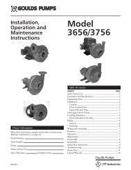
SECTION 4DIMENSIONAL DRAWING<strong>P200</strong> ADVANCED TM PLASTIC6 mm (1/4") FNPTAIR INLET13 mm(1/2") FNPTAIR EXHAUSTDIMENSIONSITEM METRIC (mm) STANDARD (inch)A 457 18.0B 66 2.6C 259 10.2D 381 15.0E 434 17.1F 99 3.9G 104 4.1H 122 4.8J 259 10.2K 231 9.1L 353 13.9M 310 12.2N 124 4.9P 157 6.2R 10 0.4DIN FLANGES 85 DIA. 3.3 DIA.T 115 DIA. 4.5 DIA.U 14 DIA. 0.6 DIA.ANSI FLANGES 79 DIA. 3.1 DIA.T 108 DIA. 4.3 DIA.U 16 DIA. 0.6 DIA.WILDEN PUMP & ENGINEERING, LLC 4 WIL-11070-E-08
SECTION 5APERFORMANCE CURVES<strong>P200</strong> ADVANCED TM PLASTIC RUBBER-FITTEDHeight .................................. 434 mm (17.1")Width ................................... 457 mm (18.0")Depth .................................... 231 mm (9.1")Est. Ship Weight ........Polypropylene 10 kg (22 lbs)PVDF 15 kg (32 lbs)PFA 18 kg (40 lbs)Air Inlet ......................................6 mm (1/4")Inlet ............................................ 25 mm (1")Outlet ......................................... 25 mm (1")Suction Lift ........................ 3.6 m Dry (11.9')9.1 m Wet (30.0')Displacement perStroke ......................... 0.32 l (.086 gal.) 1Max. <strong>Flo</strong>w Rate .................220 lpm (58 gpm)Max. Size Solids .................4.76 mm (3/16")1Displacement per stroke was calculated at 4.8 bar(70 psig) air inlet pressure against a 2 bar (30 psig)head pressure.Example: To <strong>pump</strong> 68 lpm (18 gpm) againsta discharge head pressure of 3.4 bar (50 psig)requires 4.1 bar (60 psig) and 34 Nm 3 /h (20scfm) air consumption. (See dot on chart.)Caution: Do not exceed 5.2 bar (75 psig) airsupply pressure on PFA <strong>pump</strong>s.Caution: Do not exceed 8.6 bar (125 psig) airsupply pressure on polypropylene and PVDF<strong>pump</strong>s.<strong>Flo</strong>w rates indicated on chart were determined by <strong>pump</strong>ing water.For optimum life and performance, <strong>pump</strong>s should be specified so that daily operation parameterswill fall in the center of the <strong>pump</strong> performance curve.SECTION 5BPERFORMANCE CURVES<strong>P200</strong> ADVANCED TM PLASTIC TPE-FITTEDHeight .................................. 434 mm (17.1")Width ................................... 457 mm (18.0")Depth .................................... 231 mm (9.1")Est. Ship Weight ........Polypropylene 10 kg (22 lbs)PVDF 15 kg (32 lbs)PFA 18 kg (40 lbs)Air Inlet ......................................6 mm (1/4")Inlet ............................................ 25 mm (1")Outlet ......................................... 25 mm (1")Suction Lift ........................ 3.5 m Dry (11.4')9.8 m Wet (32.0')Displacement perStroke ......................... 0.33 l (.088 gal.) 1Max. <strong>Flo</strong>w Rate .................216 lpm (57 gpm)Max. Size Solids .................4.76 mm (3/16")1Displacement per stroke was calculated at 4.8 bar(70 psig) air inlet pressure against a 2 bar (30 psig)head pressure.Example: To <strong>pump</strong> 76 lpm (20 gpm) againsta discharge head pressure of 3.1 bar (45 psig)requires 4.1 bar (60 psig) and 34 Nm 3 /h (20scfm) air consumption. (See dot on chart.)Caution: Do not exceed 5.2 bar (75 psig) airsupply pressure on PFA <strong>pump</strong>s.Caution: Do not exceed 8.6 bar (125 psig) air supplypressure on polypropylene and PVDF <strong>pump</strong>s.<strong>Flo</strong>w rates indicated on chart were determined by <strong>pump</strong>ing water.For optimum life and performance, <strong>pump</strong>s should be specified so that daily operation parameterswill fall in the center of the <strong>pump</strong> performance curve.WIL-11070-E-08 5 WILDEN PUMP & ENGINEERING, LLC
SECTION 5CPERFORMANCE CURVES<strong>P200</strong> ADVANCED TM PLASTIC PTFE-FITTEDHeight .................................. 434 mm (17.1")Width ................................... 457 mm (18.0")Depth .................................... 231 mm (9.1")Est. Ship Weight ........Polypropylene 10 kg (22 lbs)PVDF 15 kg (32 lbs)PFA 18 kg (40 lbs)Air Inlet ......................................6 mm (1/4")Inlet ............................................ 25 mm (1")Outlet ......................................... 25 mm (1")Suction Lift .......................... 2.4 m Dry (7.9')9.4 m Wet (31.0')Displacement perStroke ......................... 0.22 l (.057 gal.) 1Max. <strong>Flo</strong>w Rate .................174 lpm (46 gpm)Max. Size Solids .................4.76 mm (3/16")1Displacement per stroke was calculated at 4.8 bar(70 psig) air inlet pressure against a 2 bar (30 psig)head pressure.Example: To <strong>pump</strong> 76 lpm (20 gpm) againsta discharge head pressure of 4.5 bar (65 psig)requires 6.9 bar (100 psig) and 37 Nm 3 /h(40 scfm) air consumption. (See dot onchart.)Caution: Do not exceed 5.2 bar (75 psig) airsupply pressure on PFA <strong>pump</strong>s.Caution: Do not exceed 8.6 bar (125 psig) airsupply pressure on polypropylene and PVDF<strong>pump</strong>s<strong>Flo</strong>w rates indicated on chart were determined by <strong>pump</strong>ing water.For optimum life and performance, <strong>pump</strong>s should be specified so that daily operation parameterswill fall in the center of the <strong>pump</strong> performance curve.SECTION 6SUCTION LIFT CURVES & DATA<strong>P200</strong> Advanced Plastic Suction Lift CapabilitySuction lift curves are calibrated for <strong>pump</strong>s operating at 305m (1,000') above sea level. This chart is meant to be a guideonly. There are many variables which can affect your <strong>pump</strong>’soperating characteristics. The number of intake and dischargeelbows, viscosity of <strong>pump</strong>ing fluid, elevation (atmosphericpressure) and pipe friction loss all affect the amountof suction lift your <strong>pump</strong> will attain.WILDEN PUMP & ENGINEERING, LLC 6 WIL-11070-E-08
SECTION 7AINSTALLATIONThe <strong>Pro</strong>-<strong>Flo</strong> ® model <strong>P200</strong> Advanced <strong>plastic</strong> has a 25mm (1") inlet and 25 mm (1") outlet and is designed forflows to 220 lpm (58 gpm). The <strong>P200</strong> Advanced <strong>plastic</strong><strong>pump</strong> is manufactured with wetted parts of pure, unpigmentedPolypropylene or PVDF. The <strong>P200</strong> Advanced<strong>plastic</strong> <strong>pump</strong> is constructed with a glass fiber filled PP centersection. A variety of diaphragms and o-rings are availableto satisfy temperature, chemical compatibility, abrasion, andflex concerns.The suction pipe size should be at least 25 mm (1") diameteror larger if highly viscous material is being <strong>pump</strong>ed. Thesuction hose must be non-collapsible, reinforced type as the<strong>P200</strong> Advanced <strong>plastic</strong> <strong>pump</strong> is capable of pulling a highvacuum. Discharge piping should be at least 25 mm (1");larger diameter can be used to reduce friction losses. It iscritical that all fittings and connections are airtight or a reductionor loss of <strong>pump</strong> suction capability will result.INSTALLATION: Months of careful planning, study, andselection efforts can result in unsatisfactory <strong>pump</strong> performanceif installation details are left to chance.Premature failure and long term dissatisfaction can beavoided if reasonable care is exercised throughout the installationprocess.LOCATION: Noise, safety, and other logistical factors usuallydictate where equipment should be situated on the productionfloor. Multiple installations with conflicting requirementscan result in congestion of utility areas, leaving few choicesfor additional <strong>pump</strong>s.Within the framework of these and other existing conditions,every <strong>pump</strong> should be located in such a way that fivekey factors are balanced against each other to maximumadvantage.ACCESS: First, the location should be accessible. If it iseasy to reach the <strong>pump</strong>, maintenance personnel will have aneasier time carrying out routine inspections and adjustments.Should major repairs become necessary, ease of access canplay a key role in speeding the repair process and reducingtotal downtime.AIR SUPPLY: Every <strong>pump</strong> location should have an air linelarge enough to supply the volume of air necessary to achievethe desired <strong>pump</strong>ing rate (see Section 5). Do not exceed 5.2bar (75 psig) air supply for PFA <strong>pump</strong>s. Use air pressure upto a maximum of 8.6 bar (125 psig) for polypropylene andPVDF <strong>pump</strong>s depending on <strong>pump</strong>ing requirements.For best results, the <strong>pump</strong>s should use a 5µ (micron) air filter,needle valve and regulator. The use of an air filter before the<strong>pump</strong> will insure that the majority of any pipeline contaminantswill be eliminated.SOLENOID OPERATION: When operation is controlled bya solenoid valve in the air line, three-way valves should beused, thus allowing trapped air to bleed off and improving<strong>pump</strong> performance. Pumping volume can be set by countingthe number of strokes per minute and multiplying bydisplacement per stroke.SOUND: Sound levels are reduced using the standardWilden muffler element. Other mufflers can be used, butusually reduce <strong>pump</strong> performance.ELEVATION: Selecting a site that is well within the <strong>pump</strong>’sdynamic lift capability will assure that loss-of-prime troubleswill be eliminated. In addition, <strong>pump</strong> efficiency can beadversely affected if proper attention is not given to sitelocation.PIPING: Final determination of the <strong>pump</strong> site should notbe made until the piping problems of each possible locationhave been evaluated. The impact of current and futureinstallations should be considered ahead of time to makesure that inadvertent restrictions are not created for anyremaining sites.The best choice possible will be a site involving the shortestand straightest hook-up of suction and discharge piping.Unnecessary elbows, bends, and fittings should be avoided.Pipe sizes should be selected to keep friction losses withinpractical limits. All piping should be supported independentlyof the <strong>pump</strong>. In addition, the piping should be aligned toavoid placing stresses on the <strong>pump</strong> fittings.Flexible hose can be installed to aid in absorbing the forcescreated by the natural reciprocating action of the <strong>pump</strong>. Ifthe <strong>pump</strong> is to be bolted down to a solid location, a mountingpad placed between the <strong>pump</strong> and the foundation willassist in minimizing <strong>pump</strong> vibration. Flexible connectionsbetween the <strong>pump</strong> and rigid piping will also assist in minimizing<strong>pump</strong> vibration. If quick-closing valves are installedat any point in the discharge system, or if pulsation within asystem becomes a problem, a surge suppressor should beinstalled to protect the <strong>pump</strong>, piping and gauges from surgesand water hammer.The <strong>P200</strong> Advanced <strong>plastic</strong> <strong>Pro</strong>-<strong>Flo</strong> ® equipped <strong>pump</strong>can be installed in submersible applications only whenboth the wetted and non-wetted portions are compatiblewith the material being <strong>pump</strong>ed. If the <strong>pump</strong> is to be usedin a submersible application, a hose should be attached tothe air and pilot spool exhaust ports of the <strong>pump</strong>. Theseshould then be piped above the liquid level. The exhaustarea for the pilot spool is designed to be tapped for a 1/8"NPT fitting.When <strong>pump</strong>s are installed in applications involving floodedsuction or suction head pressures, a gate valve should beinstalled in the suction line to permit closing of the line for<strong>pump</strong> service.If the <strong>pump</strong> is to be used in a self-priming application, besure that all connections are airtight and that the suction-liftis within the ability of the model. Note: Materials of constructionand elastomer material have an effect on suction liftparameters. Please consult Wilden distributors for specifics.<strong>Pumps</strong> in service with a positive suction head are most efficientwhen inlet pressure is limited to 0.5–0.7 bar (7–10 psig).Premature diaphragm failure may occur if positive suction is0.7 bar (10 psig) and higher.THE MODEL <strong>P200</strong> ADVANCED PLASTIC WILL PASS4.76 mm (3/16") SOLIDS. WHENEVER THE POSSIBILITYEXISTS THAT LARGER SOLID OBJECTS MAY BE SUCKEDINTO THE PUMP, A STRAINER SHOULD BE USED ON THESUCTION LINE.CAUTION: DO NOT EXCEED 5.2 BAR (75 PSIG) AIRSUPPLY FOR PFA PUMPS. DO NOT EXCEED 8.6 BAR(125 PSIG) AIR SUPPLY PRESSURE FOR POLYPROPYL-ENE AND PVDF PUMPS.WIL-11070-E-08 7 WILDEN PUMP & ENGINEERING, LLC
AIR-OPERATED PUMPS: To stop the <strong>pump</strong> from operating in anemergency situation, simply close the “shut-off” valve (user supplied)installed in the air supply line. A properly functioning valvewill stop the air supply to the <strong>pump</strong>, therefore stopping output. Thisshut-off valve should be located far enough away from the <strong>pump</strong>ingequipment such that it can be reached safely in an emergencysituation.NOTE: In the event of a power failure, the shutoff valve should beclosed, if the restarting of the <strong>pump</strong> is not desirable once power isregained.SECTION 7BSUGGESTED OPERATION ANDMAINTENANCE INSTRUCTIONSOPERATION: Pump discharge rate can be controlled bylimiting the volume and/or pressure of the air supply to the<strong>pump</strong> (preferred method). An air regulator is used to regulateair pressure. A needle valve is used to regulate volume.Pump discharge rate can also be controlled by throttling the<strong>pump</strong> discharge by partially closing a valve in the dischargeline of the <strong>pump</strong>. This action increases friction loss, whichreduces flow rate. This is useful when the need exists tocontrol the <strong>pump</strong> from a remote location. When the <strong>pump</strong>discharge pressure equals or exceeds the air supply pressure,the <strong>pump</strong> will stop; no bypass or pressure relief valveis needed, and <strong>pump</strong> damage will not occur. The <strong>pump</strong> hasbeen "deadheaded." It can be restarted by reducing thefluid discharge pressure, or increasing the air inlet pressure.The Wilden <strong>P200</strong> Advanced <strong>plastic</strong> <strong>pump</strong> runs solely oncompressed air and does not generate heat, therefore yourprocess fluid temperature will not be affected.RECORDS: When service is required, a record should bemade of all necessary repairs and replacements. Over aperiod of time, such records can become a valuable tool forpredicting and preventing future maintenance problems andunscheduled downtime. In addition, accurate records makeit possible to identify <strong>pump</strong>s that are poorly suited to theirapplications.MAINTENANCE AND INSPECTIONS: Since each applicationis unique, maintenance schedules may be different forevery <strong>pump</strong>. Frequency of use, line pressure, viscosity andabrasiveness of process fluid all affect the parts life of aWilden <strong>pump</strong>. Periodic inspections have been found to offerthe best means for preventing unscheduled <strong>pump</strong> downtime.Personnel familiar with the <strong>pump</strong>’s construction and serviceshould be informed of any abnormalities that are detectedduring operation.WILDEN PUMP & ENGINEERING, LLC 8 WIL-11070-E-08
SECTION 7CTROUBLESHOOTINGPump will not run or runs slowly.1. Ensure that the air inlet pressure is at least 0.35 bar(5 psig) above startup pressure and that the differentialpressure (the difference between air inlet and liquiddischarge pressures) is not less than 0.7 bar (10 psig).2. Check air inlet filter for debris (see recommended installation).3. Check for extreme air leakage (blow by) which wouldindicate worn seals/bores in the air valve, pilot spool,main shaft.4. Disassemble <strong>pump</strong> and check for obstructions in theair passageways or objects which would obstruct themovement of internal parts.5. Check for sticking ball check valves. If material being<strong>pump</strong>ed is not compatible with <strong>pump</strong> elastomers, swellingmay occur. Replace ball check valves and sealswith proper elastomers. In addition, valve balls becomesmaller as the wear. This may cause them to becomestuck in the seats. In this case, replace balls and seats.6. Check for broken inner piston, which will prevent the airvalve spool from shifting.7. Remove plug from pilot spool exhaust, check pilot spoolexhaust for blockage.Pump runs but little or no product flows.1. Check for <strong>pump</strong> cavitation; slow <strong>pump</strong> speed down toallow thick material to flow into liquid chambers.2. Verify that vacuum required to lift liquid is not greaterthan the vapor pressure of the material being <strong>pump</strong>ed(cavitation).3. Check for sticking ball check valves. If material being<strong>pump</strong>ed is not compatible with <strong>pump</strong> elastomers, swellingmay occur. Replace ball check valves and sealswith proper elastomers. In addition, valve balls becomesmaller as the wear. This may cause them to becomestuck in the seats. In this case, replace balls and seats.Pump air valve freezes.1. Check for excessive moisture in compressed air. Installeither a dryer, or hot air generator for compressed air.Alternatively, a coalescing filter may be used to removethe water from the compressed air in some applications.Air bubbles in <strong>pump</strong> discharge.1. Check for ruptured diaphragm.2. Check tightness of outer pistons.3. Check torque of bolts and integrity of o-rings and seals,especially at intake manifold.4. Ensure pipe connections are airtight.<strong>Pro</strong>duct comes out air exhaust.1. Check for diaphragm rupture.2. Check tightness of outer pistons to shaft.WIL-11070-E-08 9 WILDEN PUMP & ENGINEERING, LLC
SECTION 8A<strong>P200</strong> ADVANCED PLASTICDIRECTIONS FOR DISASSEMBLY/REASSEMBLYCAUTION: Before any maintenance or repair is attempted,the compressed air line to the <strong>pump</strong> should be disconnectedand all air pressure allowed to bleed from the <strong>pump</strong>.Disconnect all intake, discharge, and air lines. Drain the<strong>pump</strong> by turning it upside down and allowing any fluid toflow into a suitable container. Be aware of any hazardouseffects of contact with your process fluid.TOOLS REQUIRED:13 mm (1/2") Box Wrench2 – 25 mm (1") Sockets or Adjustable WrenchAdjustable WrenchVise equipped with soft jaws (such as plywood, <strong>plastic</strong>or other suitable material)NOTE: The model used for these instructions incorporatesPTFE diaphragms and balls. Models with rubber diaphragmsand balls are the same except where noted.DISASSEMBLY:Figure 1Step 1.Please see pre-molded alignment marks on the liquid chamberand center section.Step 2. Figure 2Using the 13 mm (1/2”) box wrench, loosen the dischargemanifold from the liquid chambers.Step 3. Figure 3Remove the discharge manifold to expose the valve balls,valve seats and valve seat o-rings.WILDEN PUMP & ENGINEERING, LLC 10 WIL-11070-E-08
Step 4. Figure 4Remove the discharge valve balls, seats and valve seato-rings from the discharge manifold and liquid chamber,inspect for nicks, gouges, chemical attack or abrasivewear. Replace worn parts with genuine Wilden parts forreliable performance.Step 5. Figure 5Using a 13 mm (1/2") box wrench, remove the inlet manifold.Step 6. Figure 6Remove the inlet valve balls, seats andvalve seat o-rings from the liquid chamberand discharge manifold, inspectfor nicks, gouges, chemical attack orabrasive wear. Replace worn parts withgenuine Wilden parts for reliable performance.Step 7. Figure 7With a 13 mm (1/2") box wrench, removethe liquid chambers from the centersection.Step 8. Figure 8The liquid chamber should be removedto expose the diaphragm and outer piston.Rotate center section and removethe opposite liquid chamber.WIL-11070-E-08 11 WILDEN PUMP & ENGINEERING, LLC
Step 9. Figure 9Using two crescent wrenches or 25 mm (1") sockets, removediaphragm assembly from center section assembly.Step 10. Figure 10After loosening and removing the outer piston the diaphragmassembly can be disassembled.Step 11. Figure 11To remove the remaining diaphragmassembly from the shaft, secure shaft withsoft jaws (a vise fitted with plywood orother suitable material) to ensure shaft isnot nicked, scratched, or gouged. Usingan adjustable wrench, remove diaphragmassembly from shaft. Inspect all parts forwear and replace with genuine Wildenparts if necessary.Step 12. Figure 12Inspect diaphragms, outer and inner pistonsfor signs of wear. Replace with genuineWilden parts if necessary.WILDEN PUMP & ENGINEERING, LLC 12 WIL-11070-E-08
SECTION 8BPRO-FLO ® AIR VALVE/CENTER SECTIONDISASSEMBLY, CLEANING, INSPECTIONAIR VALVE DISASSEMBLY:CAUTION: Before any maintenance or repair is attempted,the compressed air line to the <strong>pump</strong> should be disconnectedand all air pressure allowed to bleed from the <strong>pump</strong>.Disconnect all intake, discharge, and air lines. Drain the<strong>pump</strong> by turning it upside down and allowing any fluid toflow into a suitable container. Be aware of hazardous effectsof contact with your process fluid.The Wilden <strong>P200</strong> Advanced Plastic Pump utilizes arevolutionary <strong>Pro</strong>-<strong>Flo</strong> ® air distribution system. A 6 mm(1/4") air inlet connects the air supply to the center section.<strong>Pro</strong>prietary composite seals reduce the co efficient offriction and allow the <strong>P200</strong> to run lube-free. Constructedof polypropylene, the <strong>Pro</strong>-<strong>Flo</strong> ® air distribution system isdesigned to perform in on/off, non-freezing, non-stalling,tough duty applications.TOOLS REQUIRED:3/16" Allen WrenchSnap Ring PliersO-Ring PickStep 1. Figure 1Loosen the air valve bolts utilizing a 3/16" Allen wrench.Step 2. Figure 2Remove muffler plate and air valve boltsfrom air valve assembly exposing mufflergasket for inspection. Replace if necessary.Step 3. Figure 3Lift away air valve assembly and removeair valve gasket for inspection. Replaceif necessary.Step 4. Figure 4Remove air valve end cap to expose airvalve spool by simply lifting up on endcap once air valve bolts are removed.WIL-11070-E-08 13 WILDEN PUMP & ENGINEERING, LLC
Step 5. Figure 5Remove air valve spool from air valve body by threading oneair valve bolt into the end of the spool and gently sliding thespool out of the air valve body. Inspect seals for signs of wearand replace entire assembly if necessary. Use caution whenhandling air valve spool to prevent damaging seals.NOTE: Seals should not be removed from assembly.Seals are not sold separately.Step 6. Figure 6Remove pilot spool sleeve retaining snap ring on both sidesof center section with snap ring pliers.Step 7. Figure 7Remove pilot spool sleeve from centersection.Step 8. Figure 8With o-ring pick, gently remove theo-ring from the opposite side of the“center hole” cut on the spool. Gentlyremove the pilot spool from sleeve andinspect for nicks or gouges and othersigns of wear. Replace pilot sleeveassembly or outer sleeve o-rings ifnecessary. During re-assembly neverinsert the pilot spool into the sleeve withthe “center cut” side first, this end incorporatesthe urethane o-ring and will bedamaged as it slides over the ports cutin the sleeve.NOTE: Seals should not be removedfrom pilot spool. Seals are notsold separately.Step 9. Figure 9Check center section Glyd rings forsigns of wear. If necessary, removeGlyd rings with o-ring pick andreplace.WILDEN PUMP & ENGINEERING, LLC 14 WIL-11070-E-08
SECTION 8CREASSEMBLY HINTS & TIPSASSEMBLY:Upon performing applicable maintenance to the air distributionsystem, the <strong>pump</strong> can now be reassembled. Please refer tothe disassembly instructions for photos and parts placement.To reassemble the <strong>pump</strong>, follow the disassembly instructions inreverse order. The air distribution system needs to be assembledfirst, then the diaphragms and finally the wetted path.Please find the applicable torque specifications on this page.The following tips will assist in the assembly process.• Clean the inside of the center section shaft bore to ensureno damage is done to new seals.• Stainless bolts should be lubed to reduce the possibility ofseizing during tightening.• Be sure to tighten outer pistons simultaneously on PTFEfitted<strong>pump</strong>s to ensure proper torque values.• Apply two (2) drops of Loctite ® 246 to the shaft internalthreads before the diaphragm assembly.• Concave side of disc spring in diaphragm assembly facestoward inner piston.MAXIMUM TORQUE SPECIFICATIONSPart Description<strong>Pro</strong>-<strong>Flo</strong> ® Air ValveAir Inlet Reducer BushingOuter Piston (rubber, TPE, & PTFEdiaphragm fitted)Top & Bottom Manifolds (Poly & PVDF)Liquid Chamber (Poly & PVDF)Top & Bottom Manifolds (PFA)Liquid Chamber (PFA)Torque3.1 N•m (27 in-lbs)0.9 N•m (8 in-lbs)27.1 N•m (20 ft-lbs)5.6 N•m (50 in-lbs)8.5 N•m (75 in-lbs)3.4 N•m (30 in-lbs)5.6 N•m (50 in-lbs)WIL-11070-E-08 15 WILDEN PUMP & ENGINEERING, LLC
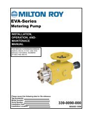
SECTION 9AEXPLODED VIEW/PARTS LISTING<strong>P200</strong>ADVANCEDPLASTICRUBBER-FITTEDWILDEN PUMP & ENGINEERING, LLC 16 WIL-11070-E-08
<strong>P200</strong> ADVANCED PLASTIC BOLTED RUBBER-FITTEDItemPart DescriptionQty.PerPump<strong>P200</strong>/PKPPPP/N<strong>P200</strong>/PKPPP/0502P/N<strong>P200</strong>/KKPPPP/N<strong>P200</strong>/KKPPP/0502P/N1 <strong>Pro</strong>-<strong>Flo</strong> ® Air Valve Assembly 1 1 01-2010-20 01-2010-20 01-2010-20 01-2010-202 End Cap 1 01-2332-20 01-2332-20 01-2332-20 01-2332-203 O-Ring, End Cap 1 01-2395-52 01-2395-52 01-2395-52 01-2395-524 Gasket, Air Valve 1 01-2615-52 01-2615-52 01-2615-52 01-2615-525 Screw, HSHC, Air Valve 1/4-20 4 01-6001-03 01-6001-05 01-6001-03 01-6001-056 Center Section 1 02-3142-20 02-3142-20 02-3142-20 02-3142-207 Bushing, Reducer 1 01-6950-20 01-6950-20 01-6950-20 01-6950-208 Removable Pilot Sleeve Assembly 1 02-3880-99 02-3880-99 02-3880-99 02-3880-999 Glyd Ring II 2 02-3210-55-225 02-3210-55-225 02-3210-55-225 02-3210-55-22510 Retaining Ring 2 00-2650-03 00-2650-03 00-2650-03 00-2650-0311 Muffler Plate 1 01-3181-20 01-3181-20 01-3181-20 01-3181-2012 Gasket, Muffler Plate 1 01-3505-52 01-3505-52 01-3505-52 01-3505-5213 Muffler 1 02-3510-99 02-3510-99 02-3510-99 02-3510-9914 Shaft, <strong>Pro</strong>-<strong>Flo</strong> ® 1 02-3810-03 02-3810-03 02-3810-03 02-3810-0315 Disc Spring (Belleville Washer) 2 02-6802-08 02-6802-08 02-6802-08 02-6802-0816 Inner Piston 2 02-3701-01 02-3701-01 02-3701-01 02-3701-0117 Outer Piston 2 02-4550-21-500 02-4550-21-500 02-4550-21-500 02-4550-21-50018 Liquid Chamber 2 02-5005-20 02-5005-20 02-5005-21 02-5005-2119 Discharge Manifold 1 02-5030-20 02-5030-20 02-5030-21 02-5030-2120 Inlet Manifold 1 02-5090-20 02-5090-20 02-5090-21 02-5090-2121 Valve Seat 4 02-1125-20 02-1125-20 02-1125-21 02-1125-2122 Valve Seat O-Ring 4 * * * *23 Flange O-Ring 4 * * * *24 Valve Ball 4 * * * *25 Flange Bolt 16 02-6181-03 02-6181-05 02-6181-03 02-6181-0526 Washer 32 02-6731-03 02-6731-05 02-6731-03 02-6731-0527 Chamber Bolt 16 02-6191-03 02-6191-05 02-6191-03 02-6191-0528 Diaphragm 2 * * * *1Air Valve Assembly includes items 2 and 3.*Refer to corresponding elastomer chart in Section 10.0502 Specialty Code = PFA Coated, ANSI FlangeAll boldface items are primary wear parts.Consult Factory for DIN Flange.WIL-11070-E-08 17 WILDEN PUMP & ENGINEERING, LLC
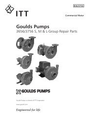
SECTION 9BEXPLODED VIEW/PARTS LISTING<strong>P200</strong>ADVANCEDPLASTICPTFE-FITTEDWILDEN PUMP & ENGINEERING, LLC 18 WIL-11070-E-08
<strong>P200</strong> ADVANCED PLASTIC BOLTED PTFE-FITTEDItemPart DescriptionQty.PerPump<strong>P200</strong>/PKPPPP/N<strong>P200</strong>/PKPPP/0502P/N<strong>P200</strong>/KKPPPP/N<strong>P200</strong>/KKPPP/0502P/N<strong>P200</strong>/TTPPPP/N<strong>P200</strong>/TTPPP/0502P/N1 <strong>Pro</strong>-<strong>Flo</strong> ® Air Valve Assembly1 1 01-2010-20 01-2010-20 01-2010-20 01-2010-20 01-2010-20 01-2010-202 End Cap 1 01-2332-20 01-2332-20 01-2332-20 01-2332-20 01-2332-20 01-2332-203 O-Ring, End Cap 1 01-2395-52 01-2395-52 01-2395-52 01-2395-52 01-2395-52 01-2395-524 Gasket, Air Valve 1 01-2615-52 01-2615-52 01-2615-52 01-2615-52 01-2615-52 01-2615-525 Screw, HSHC, Air Valve 1/4-20 4 01-6001-03 01-6001-05 01-6001-03 01-6001-05 01-6001-03 01-6001-056 Center Section 1 02-3142-20 02-3142-20 02-3142-20 02-3142-20 02-3142-20 02-3142-207 Bushing, Reducer 1 01-6950-20 01-6950-20 01-6950-20 01-6950-20 01-6950-20 01-6950-208 Removable Pilot Sleeve Assembly 1 02-3880-99 02-3880-99 02-3880-99 02-3880-99 02-3880-99 02-3880-999 Glyd Ring II 2 02-3210-55-225 02-3210-55-225 02-3210-55-225 02-3210-55-225 02-3210-55-225 02-3210-55-22510 Retaining Ring 2 00-2650-03 00-2650-03 00-2650-03 00-2650-03 00-2650-03 00-2650-0311 Muffler Plate 1 01-3181-20 01-3181-20 01-3181-20 01-3181-20 01-3181-20 01-3181-2012 Gasket, Muffler Plate 1 01-3505-52 01-3505-52 01-3505-52 01-3505-52 01-3505-52 01-3505-5213 Muffler 1 02-3510-99 02-3510-99 02-3510-99 02-3510-99 02-3510-99 02-3510-9914 Shaft, <strong>Pro</strong>-<strong>Flo</strong> ® 1 02-3840-03 02-3840-03 02-3840-03 02-3840-03 02-3840-03 02-3840-0315 Disc Spring (Belleville Washer) 2 02-6802-08 02-6802-08 02-6802-08 02-6802-08 02-6802-08 02-6802-0816 Inner Piston 2 02-3751-01 02-3751-01 02-3751-01 02-3751-01 02-3751-01 02-3751-0117 Outer Piston 2 02-4600-21-500 02-4600-21-500 02-4600-21-500 02-4600-21-500 02-4600-22 02-4600-2218 Liquid Chamber 2 02-5005-20 02-5005-20 02-5005-21 02-5005-21 02-5005-22 02-5005-2219 Discharge Manifold 1 02-5030-20 02-5030-20 02-5030-21 02-5030-21 02-5030-22 02-5030-2220 Inlet Manifold 1 02-5090-20 02-5090-20 02-5090-21 02-5090-21 02-5090-22 02-5090-2221 Valve Seat 4 02-1125-20 02-1125-20 02-1125-21 02-1125-21 02-1125-55 02-1125-5522 Valve Seat O-Ring 4 02-1220-60 02-1220-60 02-1220-60 02-1220-60 02-1220-60 02-1220-6023 Flange O-Ring 4 04-1300-60-500 04-1300-60-500 04-1300-60-500 04-1300-60-500 04-1300-60-500 04-1300-60-50024 Valve Ball 4 02-1085-55 02-1085-55 02-1085-55 02-1085-55 02-1085-55 02-1085-5525 Flange Bolt 16 02-6181-03 02-6181-05 02-6181-03 02-6181-05 02-6181-03 02-6181-0526 Washer 32 02-6731-03 02-6731-05 02-6731-03 02-6731-05 02-6731-03 02-6731-0527 Chamber Bolt 16 02-6191-03 02-6191-05 02-6191-03 02-6191-05 02-6191-03 02-6191-0528 Diaphragm 2 02-1010-55 02-1010-55 02-1010-55 02-1010-55 02-1010-55 02-1010-5529 Backup Diaphragm 2 02-1060-51 02-1060-51 02-1060-51 02-1060-51 02-1060-51 02-1060-511Air Valve Assembly includes items 2 and 3.*Refer to corresponding elastomer chart in Section 10.0502 Specialty Code = PFA Coated, ANSI FlangeAll boldface items are primary wear parts.Consult Factory for DIN Flange.WIL-11070-E-08 19 WILDEN PUMP & ENGINEERING, LLC
SECTION 10ELASTOMER OPTIONS<strong>P200</strong> ADVANCED PLASTICMaterialColorCodeDiaphragm (2)P/NValve Ball (4)P/NValve Seat O-Ring (4)P/NFlange O-Ring (4)P/NBackup DiaphragmP/NPolyurethane Natural 02-1010-50 02-1085-50 02-1220-50 04-1300-50-500 N/ABuna-N Red 02-1010-52 02-1085-52 04-2390-52-700 04-1300-52-500 N/APTFE Encapsulated Viton ® None N/A N/A 02-1220-60 04-1300-60-500 N/ANeoprene Green 02-1010-51 02-1085-51 N/A N/A 02-1060-56Viton ® Silver 02-1010-53 02-1085-53 N/A N/A N/AEPDM Blue 02-1010-54 02-1085-54 N/A N/A 02-1060-541PTFE White 02-1010-55 02-1085-55 N/A N/A N/ATetra-Flex PTFEw/NeopreneWhite 02-1010-64 N/A N/A N/A N/ATetra-Flex PTFEw/EPDMWhite 02-1010-81 N/A N/A N/A N/ASaniflex Off-White 02-1010-56 02-1085-56 N/A N/A 02-1060-561Wil-Flex Orange 02-1010-58 02-1085-58 02-1220-58 02-1370-58 N/A1Saniflex and EPDM back-up diaphragms are available upon request. Please consult your local distributor.WILDEN PUMP & ENGINEERING, LLC 20 WIL-11070-E-08
WARRANTYEach and every product manufactured by Wilden Pump and Engineering, LLC is built to meet the higheststandards of quality. Every <strong>pump</strong> is functionally tested to insure integrity of operation.Wilden Pump and Engineering, LLC warrants that <strong>pump</strong>s, accessories and parts manufactured or supplied byit to be free from defects in material and workmanship for a period of five (5) years from date of installation orsix (6) years from date of manufacture, whichever comes first. Failure due to normal wear, misapplication, orabuse is, of course, excluded from this warranty.Since the use of Wilden <strong>pump</strong>s and parts is beyond our control, we cannot guarantee the suitability of any <strong>pump</strong>or part for a particular application and Wilden Pump and Engineering, LLC shall not be liable for any consequentialdamage or expense arising from the use or misuse of its products on any application. Responsibility is limitedsolely to replacement or repair of defective Wilden <strong>pump</strong>s and parts.All decisions as to the cause of failure are the sole determination of Wilden Pump and Engineering, LLC.Prior approval must be obtained from Wilden for return of any items for warranty consideration and must beaccompanied by the appropriate MSDS for the product(s) involved. A Return Goods Tag, obtained from anauthorized Wilden distributor, must be included with the items which must be shipped freight prepaid.The foregoing warranty is exclusive and in lieu of all other warranties expressed or implied (whether written or oral)including all implied warranties of merchantability and fitness for any particular purpose. No distributor or otherperson is authorized to assume any liability or obligation for Wilden Pump and Engineering, LLC other than expresslyprovided herein.PLEASE PRINT OR TYPE AND FAX TO WILDENPUMP INFORMATIONItem # Serial #Company Where PurchasedYOUR INFORMATIONCompany NameIndustryNameTitleStreet AddressCity State Postal Code CountryTelephone Fax E-mail Web AddressNumber of <strong>pump</strong>s in facility?Number of Wilden <strong>pump</strong>s?Types of <strong>pump</strong>s in facility (check all that apply): Diaphragm Centrifugal Gear Submersible LobeOtherMedia being <strong>pump</strong>ed?How did you hear of Wilden Pump? Trade Journal Trade Show Internet/E-mail DistributorOtherONCE COMPLETE, FAX TO (909) 783-3440NOTE: WARRANTY VOID IF PAGE IS NOT FAXED TO WILDENWILDEN PUMP & ENGINEERING, LLC