Universal Serial Bus Usage Tables for HID Power Devices - USB.org
Universal Serial Bus Usage Tables for HID Power Devices - USB.org
Universal Serial Bus Usage Tables for HID Power Devices - USB.org

Create successful ePaper yourself
Turn your PDF publications into a flip-book with our unique Google optimized e-Paper software.
<strong>Universal</strong> <strong>Serial</strong> <strong>Bus</strong> <strong>Usage</strong> <strong>Tables</strong> <strong>for</strong> <strong>HID</strong> <strong>Power</strong> <strong>Devices</strong><br />
• Inputs (zero to many), each being connected to an input Flow.<br />
• Chargers (one to many).<br />
• Batteries (one to many), each capable of being exclusively connected to a Charger or to an Output.<br />
• Outputs (one to many), each being connected to an output Flow.<br />
2. <strong>Power</strong> Converters (zero to many), each having:<br />
• Inputs (one to many), each being connected to an output Flow and capable of being connected to any<br />
Output.<br />
• Outputs (one to many), each being connected to an input Flow and capable of being connected to any<br />
Input.<br />
3. Outlet Systems (zero to many), each having:<br />
• Individual Outlets (1 to many), each being connected to an output Flow.<br />
• One input Flow.<br />
• Output Flow (one per Outlet).<br />
• <strong>Power</strong> Summary (zero to many), each being connected to an output Flow.<br />
The sub-modules of a module are directly connected. For example, an Input is connected to a Charger inside a<br />
Battery System, or an Input is connected to an Output inside a <strong>Power</strong> Converter.<br />
The different modules are connected to each other and to entities outside the <strong>Power</strong> Device by Flows. The<br />
connection points are the Inputs and the Outputs of the modules. For example, a Flow connects the outside<br />
world to an Input of a Battery System; it is the main AC Flow. Or, a Flow connects the Output of a Battery<br />
System to the Input of a <strong>Power</strong> Converter; it is the battery backup DC Input of the Converter.<br />
The connection inside or outside a module could be static or dynamically controlled. For example, the<br />
connection of an Input to a Charger inside a Battery System is generally static. Or, the connection of an Input<br />
to an Outlet inside an Outlet System is generally dynamically controlled.<br />
2.3 Implementation Examples<br />
<strong>Power</strong> <strong>Devices</strong> can be implemented with one or more objects. The figures in this section illustrate how<br />
multiple objects can be contained in a single device.<br />
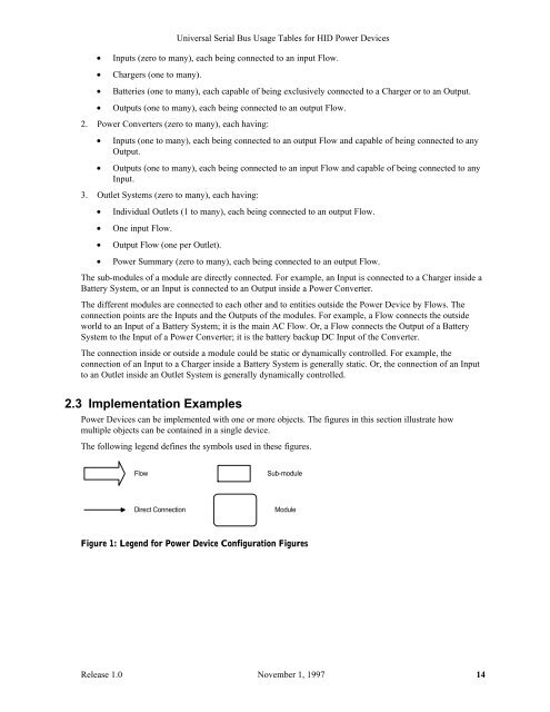
The following legend defines the symbols used in these figures.<br />
Flow<br />
Direct Connection<br />
Sub-module<br />
Module<br />
Figure 1: Legend <strong>for</strong> <strong>Power</strong> Device Configuration Figures<br />
Release 1.0 November 1, 1997 14