NEW INDEXABLE DRILL FOR HOLE MAKING - Korloy.com
NEW INDEXABLE DRILL FOR HOLE MAKING - Korloy.com
NEW INDEXABLE DRILL FOR HOLE MAKING - Korloy.com

Create successful ePaper yourself
Turn your PDF publications into a flip-book with our unique Google optimized e-Paper software.
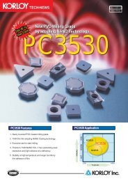
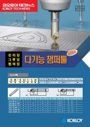
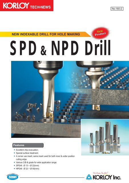
No:160-2<strong>NEW</strong> <strong>INDEXABLE</strong> <strong>DRILL</strong> <strong>FOR</strong> <strong>HOLE</strong> <strong>MAKING</strong>SPD NPD Drill&FeaturesExcellent chip evacuation.Special surface treatment.4 corner use insert, same insert used for both inner & outter positioncutting edge.Various C/B & grade for wide application range.SPDrill : Ø 13 ~ Ø 22(mm)NPDrill : Ø 23 ~ Ø 50(mm)
<strong>NEW</strong> <strong>INDEXABLE</strong> <strong>DRILL</strong> <strong>FOR</strong> <strong>HOLE</strong> <strong>MAKING</strong>Characteristics of SPD & NPD1. Excellent chip evacuationWide chip pocket area.• 20% expanded chip pocket area.• Different pocket area applied alongthe shank of drill.• Good chip evacuation at highspeed.• Rigid shank.2. Special surface treatmentSPDrill(Superior Piercing Drill)NPDrill(New Piercing Drill)Diameter : ∅ 13 ~ ∅ 22(mm)Diameter : ∅ 23 ~ ∅ 50(mm)• Excellent abrasive wear resistance ac<strong>com</strong>plished due to the special surface treatment.• Prolonged tool life.• Strong and luxury image of metallic color.2
<strong>NEW</strong> <strong>INDEXABLE</strong> <strong>DRILL</strong> <strong>FOR</strong> <strong>HOLE</strong> <strong>MAKING</strong>Characteristics of SPD & NPD3. 4 corner use insertSPMT for SPDrillSPDrill inserts internal & external edge application2134• DM C/B guarantees good chip breaking in small holemaking by its unique chip breaker design• Easy substitution of 4 corner inserts• Internal &external same insert spacing• Grade· Steel : PC3535 · Cast iron : PC6510· Stainless steel : PC9530· Aluminum : H01• SPDrill hole size : ∅ 13 ~ ∅ 22(mm)4. 4 corner use insertNPM(E)T for NPDrillNPDrill inserts internal &external edge application31124324• Edge 1 2 for external edge & Edge 3 4 for internal edge.• Efficient 4 corner use.NPM(E)T - DM, DS, DR, DAC/B + Grade applicationDM DS DR DAPC3535SteelPC6510Cast ironPC9530StainlessPC3535Soft steelH01Aluminum• NPDrill hole size : ∅ 23 ~ ∅ 50(mm) • Strong cutting edge • Good performance at high feed3
<strong>NEW</strong> <strong>INDEXABLE</strong> <strong>DRILL</strong> <strong>FOR</strong> <strong>HOLE</strong> <strong>MAKING</strong>Characteristics of SPD & NPD5. Excellent surface finishSurface finishRa(µm)4.03.53.02.52.01.51.00.500.0024 0.0032 0.004 0.0052 0.006 0.0072 0.008 (ipr)0.06 0.08 0.1 0.13 0.15 0.18 0.2 Feed(mm/rev)KORLOY’s NPD&SPD show excellent surface finish even in high feed operationCutting condition• KORLOY <strong>DRILL</strong> : SPD190-25-3,I/S : SPMT060204-DM(PC9530)· V=150m/min, d: 25mm, wet.· V=500 sfm, d: 1 inch, wet.• Workpiece : SCM440(AISI4140, 42CrMo4)Test result• Surface roughness of KORLOY drill: Under 2.0µm6. Machined hole diameter accuracyVariation of machined holeVariation of Diameter(µm)403530252015100.0024 0.0032 0.004 0.0052 0.006 0.0072 0.008 (ipr)0.06 0.08 0.1 0.13 0.15 0.18 0.2 Feed(mm/rev)Cutting condition• KORLOY Drill : NPD260-32-3,I/S : NPMT252808-DM(PC3535)· V=150m/min, d: 25mm, Wet· V=500 sfm, d: 1 inch, Wet• Workpiece : SCM440(AISI4140, 42CrMo4)Test result• Variation of diameter is better thanA-maker7. Long tool lifeWear resistanceFlank Wear(mm)0.120.100.080.060.040.020V=130 m/min, f=0.11 mm/rev. WetV=430 sfm, f=0.0044 ipr. Wet12 36 84 132 204 288 384 480 Machined holesCutting condition• KORLOY <strong>DRILL</strong> : SPD190-25-3, I/S :SPMT060204-DM(PC9530)· V=110m/min, f=0.11mm/rew. d=25mm, Wet· V=363 sfm, f=0.0044 ipr. d=1 inch, Wet• Workpiece : SCM440 (AISI4140, 42CrMo4)480 holesTest result• Longer tool life and better wear resistancethan A-makerA-maker edge<strong>Korloy</strong> edge4
<strong>NEW</strong> <strong>INDEXABLE</strong> <strong>DRILL</strong> <strong>FOR</strong> <strong>HOLE</strong> <strong>MAKING</strong>SPD & NPD InsertNPET-DRDesignation Diameter (mm) I d t r d1 GradeNPET222408-DR ∅ 23 ~ ∅ 24 8.3 8.2 2.5 0.8 2.8NPET252808-DR ∅ 25 ~ ∅ 28 9.3 9.2 3.3 0.8 3.4NPET293208-DR ∅ 29 ~ ∅ 32 10.3 10.2 3.3 0.8 3.4 PC3535(Soft Steel)NPET334008-DR ∅ 33 ~ ∅ 40 13 12.9 3.97 0.8 4.0NPET415008-DR ∅ 41 ~ ∅ 50 15.3 15.2 4.76 0.8 4.5NPET-DADesignation Diameter (mm) I d t r d1 GradeNPET222408-DA ∅ 23 ~ ∅ 24 8.3 8.2 2.5 0.8 2.8NPET252808-DA ∅ 25 ~ ∅ 28 9.3 9.2 3.3 0.8 3.4NPET293208-DA ∅ 29 ~ ∅ 32 10.3 10.2 3.3 0.8 3.4 H01(Aluminum)NPET334008-DA ∅ 33 ~ ∅ 40 13 12.9 3.97 0.8 4.0NPET415008-DA ∅ 41 ~ ∅ 50 15.3 15.2 4.76 0.8 4.5Insert and drill application per each hole diameterWork piece : SCM440, Hole size : ∅ 17(mm), Depth : 40 mm• I/S : SPMT060204-DM PC3535• Drill : SPD170-25-3Work piece : STAINLESS STEEL, hole size : ∅ 27(mm), Depth : 45mm• I/S : NPMT252808-DS PC9530• Drill : NPD270-32-26
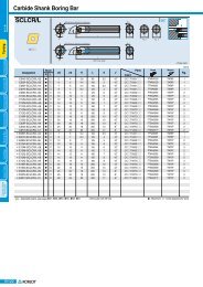
<strong>NEW</strong> <strong>INDEXABLE</strong> <strong>DRILL</strong> <strong>FOR</strong> <strong>HOLE</strong> <strong>MAKING</strong>SPD & NPD USER’S GUIDE1. SPDrillHolder Insert D D1 D2 L1 L2 L3 LPartSCREW WRENCHSPD130-20-313 20 25 39 56 50 106SPD140-20-3 SPMT050203-DM 14 20 25 42 60 50 110 FTNA0204 TW06PSPD150-20-3SPD160-25-3151620252535454864675056114123SPD170-25-317 25 35 51 70 56 126SPMT060204-DMSPD180-25-318 25 35 54 74 56 130FTKA02206SSPD190-25-3SPD200-25-3192025253535576077825656133138TW07SSPD210-25-3SPD220-25-3SPMT070204-DM 212225253535636685885656141144FTKA025652D, 3D and 4D are availableSPD 170-25-3SPDrill Hole size : ∅ 17.0mm shank diameter : ∅ 25mm Aspect ratio (2, 3, 4)• Make appropriate choice for your machining. ∅ 13~ ∅ 22(mm) for SPDrill, ∅ 23~ ∅ 50(mm)for NPDrill.7
<strong>NEW</strong> <strong>INDEXABLE</strong> <strong>DRILL</strong> <strong>FOR</strong> <strong>HOLE</strong> <strong>MAKING</strong>SPD & NPD USER’S GUIDE2. NPDrillHolder Insert D D1 D2 L1 L2 L3 LPartScrew WrenchNPD230-32-323 32 45 69 93 60 153NPD240-32-3NPD250-32-3NPD260-32-3NPD270-32-3NPD280-32-3NPD290-32-3NPM(E)T222408-NPM(E)T252808-24252627282932323232323245454545454572757881848796100103107111114606060606060156160163167171174FTKA02565FTKA0307TW07STW09SNPD300-32-3NPD310-32-3NPD320-32-3NPD330-40-3NPD340-40-3NPD350-40-3NPM(E)T293208-NPM(E)T334008-30313233343532323240404045454550505090939699102105119122125131134137606060707070179182185201204207 FTKA03508 TW15SNPD360-40-3NPD400-40-33640404050501081201411557070211225NPD450-40-345 40 60 135 174 70 244NPD500-40-3NPM(E)T415008-50 40 60 150 193 70 263FTKA0408 TW15S2D, 3D and 4D are availableHow to calculate P(KW)P = 425 x Ks x V x f x D / 10 7 (KW)Ks(Kg/mm 3 ) : specific cutting force (see <strong>Korloy</strong> catalog)Velocity : V(m/min) Feed : f (mm/rev) Diameter : D(mm)Examples• W.P = SCM440, Ks = 254, V=100m/min, f=0.1mm/rev, D=20mm• P(KW)=425 254 100 0.1 20/10,000,000=2.159KW8
<strong>NEW</strong> <strong>INDEXABLE</strong> <strong>DRILL</strong> <strong>FOR</strong> <strong>HOLE</strong> <strong>MAKING</strong>SPD & NPD USER’S GUIDE4. SPDrill, NPDrill Technical informationPowerCoolant pressurePower(kw)12108642f=0.05mm/revf=0.2mm/revf=0.15mm/revf=0.1mm/revCoolant pressure( /min)3530252015105Re<strong>com</strong>mended coolant volumeMinimum coolant volume013 20 30 40 55013 20 30 40 55Diameter(mm)Diameter(mm)This plots Power as a function of cutting diameter.The power can be changed by efficiency of machineor wear at cutting edge.Appropriate pressure for NPD &SPD is 5kg/cm 2 and more.This plots coolant pressure as a function of cutting diameter.The coolant pressure can be changed by workpiece andcutting condition.Machining with careInclined surface Half circle Hole expanding Interfered hole Overlapped boardsDecrease feed rate 30~50% when you perform these kind of machining below.Trouble shootingTroubleChatterLong chipWearChippingNoiseFactorJammed chipWrong conditionWrong V Wrong coolant pressureWrong gradeWrong conditionWrong gradeWrong conditionFlank wearSolutionV = UP, Feed = UPAlloy, Carbon steel : V=UP, f=UPSoftsteel, Stainless : V=UP, f=DOWNV = DOWN, Coolant Pressure = UPGrade changeFeed = DOWNGrade changeV = DOWN, feed = DOWNInsert changeCoolnat pressure is very important factor when machining.Low coolant pressure may cause shortened tool life by chattering or cutting edge wear.9
<strong>NEW</strong> <strong>INDEXABLE</strong> <strong>DRILL</strong> <strong>FOR</strong> <strong>HOLE</strong> <strong>MAKING</strong>SPD & NPD USER’S GUIDE3. Re<strong>com</strong>mended cutting conditionISOPPMWork pieceHardnessW/P(H )LowcarbonsteelHighcarbonsteelLowalloy steelLowalloy steel(heat)Highalloy steelHighalloy steel(heat)AusteniteAustenite(Cast steel)80-180180-280140-260200-40050-260220-450135-275Ni>8%150-250C/B and GradeC/B Grade1st2nd1st1st1st1st2nd1st2nd1st2nd1st1st1st2ndDMDSDMDMDSDMDRDMDSDMDRDSDMDSDMPC3535PC9530PC3535PC3535PC9530PC3535PC3535PC3535PC9530PC3535PC3535PC9530PC9530PC9530PC9530Vm/minsfm180(130-230)600(430-760)160(110-210)530(360-700)130(80-180)430(265-600)120(70-170)400(230-560)100(50-150)330(650-500)70(40-120)230(132-400)60(40-110)200(132-363)90(50-140)300(165-462)80(50-130)265(165-430)50(30-100)165(100-340)50(30-100)165(100-340)80(50-130)265(165-430)80(50-130)265(165-430)70(40-110)230(132-365)70(40-110)230(132-365)Condition(L=3D)feed(mm/rev) (ipr)∅ 13~15 ∅ 16~24 ∅ 25~32 ∅ 33~40 ∅ 410.04-0.080.0016-0.00320.04-0.080.0016-0.00320.04-0.080.0016-0.00320.04-0.100.0016-0.00400.04-0.100.0016-0.00400.04-0.080.0016-0.00320.04-0.080.0016-0.00320.04-0.080.0016-0.00320.04-0.080.0016-0.00320.04-0.080.0016-0.00320.04-0.080.0016-0.00320.04-0.080.0016-0.00320.04-0.080.0016-0.00320.04-0.080.0016-0.00320.04-0.080.0016-0.00320.04-0.080.0016-0.00320.04-0.100.0016-0.00400.04-0.100.0016-0.00400.06-0.120.0024-0.00480.06-0.130.0024-0.00520.04-0.100.0016-0.00400.04-0.100.0016-0.00400.04-0.100.0016-0.00400.04-0.100.0016-0.00400.04-0.100.0016-0.00400.04-0.100.0016-0.00400.04-0.100.0016-0.00400.04-0.100.0016-0.00400.04-0.100.0016-0.00400.04-0.100.0016-0.00400.05-0.080.0020-0.00320.05-0.100.0020-0.00400.05-0.120.0020-0.00480.10-0.150.0040-0.00600.10-0.180.0040-0.00640.06-0.130.0024-0.00560.06-0.130.0024-0.00560.08-0.140.0032-0.00560.08-0.140.0032-0.00560.06-0.120.0024-0.00480.06-0.120.0024-0.00480.06-0.120.0024-0.00480.06-0.120.0024-0.00480.06-0.120.0024-0.00480.06-0.120.0024-0.00480.04-0.080.0020-0.00400.05-0.100.0020-0.00400.08-0.150.0032-0.00600.11-0.200.0044-0.00800.11-0.200.0044-0.00800.10-0.180.0040-0.00720.10-0.180.0040-0.00720.10-0.180.0040-0.00720.10-0.180.0040-0.00720.08-0.140.0032-0.00560.08-0.140.0032-0.00560.08-0.140.0032-0.00560.08-0.140.0032-0.00560.08-0.140.0032-0.00560.08-0.140.0032-0.00560.08-0.120.0032-0.00480.08-0.120.0032-0.00480.10-0.200.0040-0.00800.13-0.250.0052-0.01000.13-0.250.0052-0.01000.12-0.200.0048-0.00800.12-0.200.0048-0.00800.12-0.200.0048-0.00800.12-0.200.0048-0.00800.10-0.180.0040-0.00720.10-0.180.0040-0.00720.10-0.180.0040-0.00720.10-0.180.0040-0.00720.10-0.180.0040-0.00720.10-0.180.0040-0.0072Machined hole tolerance as per D.O.C.Test cutting conditionD.O.C2 x D3 x D4 X DMachined hole toleranceDDD+0.15- 0.1+0.2- 0.1+0.25- 0.1(mm)(mm)(mm)VfWorkpieceMetric130~200 m/min0.04~0.15 mm/rev42CrMo4Inch430~660 sfm0.0016~0.006 iprAlSl414010
<strong>NEW</strong> <strong>INDEXABLE</strong> <strong>DRILL</strong> <strong>FOR</strong> <strong>HOLE</strong> <strong>MAKING</strong>SPD & NPD USER’S GUIDE3. Re<strong>com</strong>mended cutting conditionISOMMKKKWork pieceHardnessW/P(HB)FerriteMartensiteNi-alloyTi-alloyHighhardnessGrayDuctileGraphiteAluminumCopper135-275130-400130-400400-150-220130-240200-30030-150150-160C/B and GradeC/B Grade1st DS2nd DM1st DS2nd DM1st DR1st DR1st DM1st DM2nd DR1st DM2nd DR1st DA2nd DM1st DA2nd DMPC9530PC9530PC9530PC9530PC3530PC3530PC6510PC6510PC3535PC6510PC3535H01H01H01H01Vm/minsfm110(60-150)365(200-500)100(60-140)330(200-462)40(30-80)132(100-265)40(30-80)132(100-265)40(30-70)132(100-231)30(20-60)100(65-200)180(140-230)600(465-760)130(90-180)430(300-600)110(70-160)365(230-530)120(70-150)400(230-500)100(50-130)330(165-430)250(150-300)825(500-990)200(150-250)660(500-825)200(150-250)660(500-825)150(100-200)500(330-660)Condition(L=3D)feed(mm/rev) (ipr)∅ 13~15 ∅ 16~24 ∅ 25~32 ∅ 33~40 ∅ 41~0.04-0.080.0016-0.00320.04-0.080.0016-0.00320.04-0.060.0016-0.00240.04-0.060.0016-0.00240.04-0.060.0016-0.00240.04-0.060.0016-0.00240.04-0.120.0016-0.00480.04-0.100.0016-0.00400.04-0.100.0016-0.00400.04-0.100.0016-0.00400.04-0.100.0016-0.00400.04-0.120.0016-0.00480.04-0.120.0016-0.00480.04-0.100.0016-0.00400.04-0.100.0016-0.00400.04-0.120.0016-0.00480.04-0.120.0016-0.00480.04-0.080.0016-0.00320.04-0.080.0016-0.00320.04-0.080.0016-0.00320.04-0.080.0016-0.00320.06-0.140.0024-0.00560.05-0.120.0020-0.00480.05-0.120.0020-0.00480.05-0.120.0020-0.00480.05-0.120.0020-0.00480.06-0.140.0024-0.00560.06-0.140.0024-0.00560.05-0.120.0020-0.00480.04-0.100.0016-0.00400.06-0.140.0024-0.00560.06-0.140.0024-0.00560.06-0.100.0024-0.00400.06-0.100.0024-0.00400.06-0.100.0024-0.00400.06-0.100.0024-0.00400.08-0.180.0032-0.00720.06-0.140.0024-0.00560.06-0.140.0024-0.00560.06-0.140.0024-0.00560.06-0.140.0024-0.00560.08-0.160.0032-0.00640.08-0.160.0032-0.00640.08-0.140.0032-0.00560.06-0.120.0032-0.00480.08-0.180.0032-0.00720.08-0.180.0032-0.00720.08-0.120.0032-0.00480.08-0.120.0032-0.00480.08-0.120.0032-0.00480.08-0.120.0032-0.00480.10-0.200.0040-0.00800.08-0.200.0032-0.00800.08-0.180.0032-0.00720.08-0.180.0032-0.00720.08-0.180.0032-0.00720.10-0.200.0040-0.00800.10-0.200.0040-0.00800.10-0.180.0040-0.00680.10-0.150.0040-0.00600.12-0.200.0048-0.00800.12-0.200.0048-0.00800.08-0.150.0032-0.00600.08-0.150.0032-0.00600.08-0.150.0032-0.00600.08-0.150.0032-0.00600.12-0.250.0048-0.01000.10-0.220.0040-0.00880.10-0.200.0040-0.00800.10-0.220.0040-0.00880.10-0.200.0040-0.00800.12-0.250.0048-0.01000.12-0.250.0048-0.01000.12-0.200.0048-0.00800.12-0.180.0048-0.0072Application Tips1. Decrease feed rate 20~30% when using aspect ratio 4D drill.(You may increase feed rate 10~20% when using aspect ratio 2D drill)2. Apply appropriate cutting condition according to workpiece shape and hardness.3. Decrease feed rate 30~50% when overlapped board drilling.4. Decrease feed rate 20~30% when poor workpiece clamping and low rigidity of machine.5. Decrease feed rate 30~50% early in the operation when inclined surface drilling.6. When maximum depth operation, check chip evacuation.(In case of bad chip evacuation, apply step drilling of change to longer drill)7. When hole expanding, adjust cutting speed and feed rate.(It may cause long chip)11