
You also want an ePaper? Increase the reach of your titles
YUMPU automatically turns print PDFs into web optimized ePapers that Google loves.
<strong>Catalog</strong> <strong>50A</strong>Leaders in precisionapplication components,control system technology,and application datamanagement.www.teejet.comTechnologies
n COMPANY Newsn product informationn image LIBRARYn technical support– Data Sheets– Parts ListTable of ContentsSelection Guide<strong>TeeJet</strong>® Broadcast Nozzle Selection Guide ..........2–3<strong>TeeJet</strong> Specialty Application NozzleSelection Guide .................................4–5<strong>TeeJet</strong> Turfgrass Nozzle Selection Guide ............6–7<strong>TeeJet</strong> Liquid Fertilizer Nozzle Selection Guide. . . . . . . . 8Broadcast NozzleTurbo <strong>TeeJet</strong>® Wide Angle Flat Spray Tips ............ 9Turbo TwinJet® Twin Flat Spray Tips .................10Turbo <strong>TeeJet</strong>® Induction Flat Spray Tips .............11XR <strong>TeeJet</strong>® Extended Range Flat Spray Tips ..........12XRC <strong>TeeJet</strong> Extended Range Flat Spray Tips ........13AIXR <strong>TeeJet</strong>® Air Induction Flat Spray Tips ............14AI <strong>TeeJet</strong>® Air Induction Flat Spray Tips ..............15AIC <strong>TeeJet</strong> Air Induction Flat Spray Tips ............16TwinJet® Twin Flat Spray Tips ........................17DG TwinJet® Twin Flat Spray Tips .....................18Turbo <strong>TeeJet</strong>® Duo Dual Flat Fan Tips ................19<strong>TeeJet</strong> VisiFlo® Flat Spray Tips .......................20DG <strong>TeeJet</strong>® Drift Guard Flat Spray Tips ...............21<strong>TeeJet</strong> Double Outlet Flat Spray Tips ................22<strong>TeeJet</strong> Off-Center Flat Spray Tips –Smaller Capacities ................................22Turbo FloodJet® Wide Angle Flat Spray Tips .........23TurfJet Wide Angle Flat Fan Spray Nozzles .........24Quick Turbo FloodJet Wide AngleFlat Spray Tips ....................................25K, TK, QCK, FloodJet Spray Tips ......................26TKT Turbo FloodJet Wide Angle Flat Spray Tips .......26<strong>TeeJet</strong> Disc-Core Type Cone Spray Tips ...............27ConeJet® VisiFlo Hollow Cone Spray Tips .......28–29FullJet® Wide Angle Full Cone Spray Tips .............30Boomless NozzlesTFW Turbo FloodJet Extra Wide AngleFlat Spray Tips ...................................31XP BoomJet® Boomless Flat Spray Nozzles ......32–33BoomJet® Boomless Nozzles with Extra WideFlat Spray Projection .............................34<strong>TeeJet</strong> Swivel Spray Nozzles with Off-CenterFlat Spray Tips—Larger Capacities .............. 34FieldJet® Boomless Nozzles with Extra WideFlat Spray Projection .............................35Banding NozzlesConeJet VisiFlo Hollow Cone Spray Tips .............36AI <strong>TeeJet</strong> Air Induction Even Flat Spray Tips ........37DG <strong>TeeJet</strong> Drift Guard Even Flat Spray Tips .........38<strong>TeeJet</strong> Even Flat Spray Tips .........................39TwinJet Even Flat Spray Tips ........................40AIUB <strong>TeeJet</strong> Banding and DirectedSpray Nozzles ....................................41<strong>TeeJet</strong> Full Cone Spray Tips .........................42<strong>TeeJet</strong> UB—Underleaf Banding Spray Tips ............42ConeJet Ceramic VisiFlo Spray Tips ..................43Specialty NozzlesAITX ConeJet® Air Induction Hollow Cone Spray Tips . . 44<strong>TeeJet</strong> VisiFlo Hollow Cone Spray Tips ...............45<strong>TeeJet</strong> VisiFlo Flat Spray Tips .........................45<strong>TeeJet</strong> Disc-Core Type Hollow Cone Spray Tips ........46<strong>TeeJet</strong> Disc-Core Type Full Cone Spray Tips ..........47Fertilizer NozzlesStreamJet SJ-3 Fertilizer Nozzles .....................48StreamJet SJ-7 Fertilizer Nozzles .....................49<strong>TeeJet</strong> Flow Regulators ..............................50StreamJet® Solid Stream Spray Nozzles ..............51Tank Rinsing Nozzles<strong>TeeJet</strong> Tank Rinsing Nozzles .........................52<strong>TeeJet</strong> Container Rinsing Nozzles ....................52<strong>TeeJet</strong> Eductor Nozzles ..............................53<strong>TeeJet</strong> Jet Agitators. . . . . . . . . . . . . . . . . . . . . . . . . . . . . . . . . . 53Boom ComponentsQuick <strong>TeeJet</strong>® Multiple Nozzle BodyAssemblies for Dry Booms ................... 54–55<strong>TeeJet</strong> Vari-Spacing Clamps for Useon Dry Boom Quick <strong>TeeJet</strong> Bodies ................54Quick <strong>TeeJet</strong> Multiple Nozzle Body Assemblies ......56Quick <strong>TeeJet</strong> Multiple Nozzle Body Assemblieswith Fertilizer Outlets for Dry Booms .............56Quick <strong>TeeJet</strong> Single Nozzle Bodiesfor Dry Booms ....................................57Quick <strong>TeeJet</strong> Multiple Nozzle Bodiesfor Wet Booms ............................... 58–59QC 360 Quick <strong>TeeJet</strong> Nozzle Bodywith CAM-LOC Adapter ..........................58Quick <strong>TeeJet</strong> Multiple Nozzle Bodieswith Fertilizer Outlets for Wet Booms ............60Quick <strong>TeeJet</strong> Triple and Single Nozzle Bodiesfor Wet Booms ...................................61Quick <strong>TeeJet</strong> Adapters and Accessories ..............62Quick <strong>TeeJet</strong> Caps for Hardi Nozzle Bodies ...........62Quick <strong>TeeJet</strong> Caps ...................................63<strong>TeeJet</strong> ChemSaver® Diaphragm Check Valves ........64<strong>TeeJet</strong> Nozzle Body ChemSaver Check Valves ........65<strong>TeeJet</strong> Nozzle Body ChemSaverAir Shutoff Valves ................................65<strong>TeeJet</strong> Row Application Kit ..........................66<strong>TeeJet</strong> Specialty Valves ..............................66<strong>TeeJet</strong> Swivel Nozzle Bodies .........................67<strong>TeeJet</strong> Hose Drops ..................................67Table Of Contents
<strong>TeeJet</strong> Hose Shank Nozzle Bodies....................68<strong>TeeJet</strong> Split Eyelet Nozzle Bodies.....................68<strong>TeeJet</strong> Nozzle Parts............................... 69–70Valves & ManifoldsDirectoValve® B Style Motors..................... 71–72DirectoValve Electric PressureRegulating Valves............................. 73–75DirectoValve Butterfly Regulating Valve ..............74DirectoValve 344 Series ElectricShutoff Valves................................. 76–77DirectoValve 346 Series Shutoff Valves ........... 78–79DirectoValve 356 Series FlangedShutoff Valves................................. 80–81Normally Open Valve............................. 82–83DirectoValve 440 Series ManifoldShutoff Valves................................. 84–85DirectoValve 450 Series Shutoff Manifold......... 86–87DirectoValve 490 Series Shutoff Manifold......... 88–89DirectoValve 460 Series 2-Way Manifold.......... 90–91DirectoValve 460 Series 3-Way Manifold.......... 92–93DirectoValve 450FB and 460FBFlow Back Manifold ........................... 94–95DirectoValve Flange Fittings...................... 96–97DirectoValve Electrical Connectors. . . . . . . . . . . . . . . . . . . 98DirectoValve 2-Way ElectricallyOperated Solenoid Valves.........................99DirectoValve 3-Way ElectricallyOperated Solenoid Valves....................... 100DirectoValve 340 Series2-Way Manual Shutoff Ball Valves ............... 101DirectoValve 340 Series3-Way Manual Bypass Ball Valves................ 102DirectoValve Manual PressureRelief/Regulating Valves........................ 103DirectoValve Manual Control Valves................ 104TeeValve® Control Valves........................... 104<strong>TeeJet</strong> Throttling Valves............................ 104Strainers<strong>TeeJet</strong> Tip Strainers................................ 105<strong>TeeJet</strong> Line Strainers.......................... 105–108Spray GunsGunJet® Spray Guns...................... 109–110, 112MeterJet® Spray Guns .............................. 111<strong>TeeJet</strong> Lawn Spray Guns........................... 111TriggerJet® Spray Guns........................ 113–114ConeJet Adjustable Spray Tips..................... 115<strong>TeeJet</strong> Shutoff Valves and Spray Guns.............. 116<strong>TeeJet</strong> ElectronicsControls Selection Guide........................... 117GPS Guidance Selection Guide ..................... 118CenterLine 220 Guidance System.................. 119CenterLine® 230BP Guidance System............... 120BoomPilot Automatic Boom Section Control...... 121FieldPilot® Assisted Steering System............ 122–123GPS Guidance Accessories......................... 124GPS Receivers...................................... 125854 Sprayer Control.......................126, 129, 130844 Series Sprayer Controls...............127, 129, 130834 Series Sprayer Controls...............128, 129, 131ARC and TASC® Consoles and Systems........ 132–136Airmatic®, AirJet® Sprayer Control. . . . . . . . . . . . . . . . . . . 137LH 4000 Sprayer Control...................... 138–13985 Series Sprayer Control...................... 140–141LH 500 Slurry Controller....................... 142–143LH 765 and LH 865 Grain Loss Monitors ............ 144LH 500C Combine Monitor......................... 145LH 500 Tramline Controller.................... 146–14770 Series Monitors............................ 148–149744A Manual Sprayer Control ...................... 150ISOBUS 11783 Cabling Standard................... 151PowerLink 640 ISOBUS Virtual Terminal. . . . . . . . . . . . . 152IC Series ISO Job Computers........................ 153Legacy® 6000 Precision Farming System....... 154–158Legacy 6000 Roadway Management System .. 159–161Flow Meters and D Series Flow Meters........ 162–163Speed and Pressure Sensors........................ 164Speed Sensor and Flow Control Cables............. 165Regulating Valves ............................. 166–167Direct Chemical InjectionSystem Components....................... 168–172Technical InformationFormulas and Factors......................... 173–174Spray Coverage Information........................ 174Nozzle Nomenclature .............................. 174Information About Spray Pressure.................. 175Area Measurement................................. 176Sprayer Calibration................................. 177Calibration/Adjustment Accessories................ 178Spray Tip Wear. . . . . . . . . . . . . . . . . . . . . . . . . . . . . . . . . . . . . . 179Spray Distribution Quality.......................... 180Droplet Size and Drift Information.................. 181Drop Size Classification........................ 182–183Drift Causes and Control...................... 184–185Drift Measurement Systems........................ 186Plumbing Diagrams................................ 187Worldwide Directory of Representatives....... 188–191Terms and Conditions.............................. 192TABLE OF CONTENTS
Broadcast Nozzle Selection GuideHerbicidesfungicidesPost-emergencesoilappliedcontactsystemiccontactsystemicReference page 9very GOOD very GOOD very GOOD very GOODat pressures below 30 PSI (2.0 bar)Reference page 9GOOD GOOD EXCELLENT GOOD EXCELLENTReference page 10GOOD EXCELLENT EXCELLENT EXCELLENT EXCELLENTat pressures below 30 PSI (2.0 bar)Reference page 10very GOOD very GOOD EXCELLENT very GOOD EXCELLENTReference page 11EXCELLENT EXCELLENT EXCELLENT,Reference pages 12–13EXCELLENT GOOD EXCELLENT GOOD,at pressures below 30 PSI (2.0 bar)Reference pages 12–13GOOD GOOD very GOOD GOOD very GOODReference page 14very GOOD GOOD EXCELLENT GOOD EXCELLENT,Reference pages 15–16very GOOD GOOD EXCELLENT GOOD EXCELLENTReference page 17EXCELLENTEXCELLENTReference page 18very GOOD very GOOD EXCELLENT very GOOD EXCELLENTReference page 19EXCELLENT EXCELLENT EXCELLENT EXCELLENTat lower pressuresReference page 19very GOOD very GOOD EXCELLENT very GOOD EXCELLENTReference page 23EXCELLENT very GOOD very GOODReference page 24EXCELLENT EXCELLENT EXCELLENTReference page 25EXCELLENTReference page 137EXCELLENT EXCELLENT EXCELLENT EXCELLENT EXCELLENTNote: Consult the chemical manufacturer’s product label for specific rate and application recommendations.2SELECTION GUIDE
insecticidesTEEJETcontactsystemicdriftmanagementsprayangletipcapacitIES visiflo ®polymervpvisifloceramicvKvisiflostainlesssteelVS8001-SSstainlesssteelssvery GOOD very GOOD very GOODGOOD EXCELLENT very GOOD110º 01–08 •EXCELLENT EXCELLENT very GOODvery GOOD EXCELLENT EXCELLENT110º 02–06 •EXCELLENT EXCELLENT 110º 015–06 •EXCELLENT GOOD GOODGOOD very GOOD very GOODxr 80º,xr 110ºxrC 80º,xrC 110º01–15 110º • • •015–08 110º • •GOOD EXCELLENT EXCELLENT 110º 015–06 •GOOD EXCELLENT EXCELLENTAI 110ºAIC 110º015–08015–10 • •••EXCELLENT65º, 80º,110º01–10 •very GOOD EXCELLENT very GOOD 110º 015–08 •EXCELLENT EXCELLENT very GOODvery GOOD EXCELLENT EXCELLENT110º 01–08 •very GOOD EXCELLENT 140º– 150º 02–10 • •EXCELLENT EXCELLENT 140º–150º 02–15 • •EXCELLENT 150º 15–120 •EXCELLENT EXCELLENT EXCELLENT contact your regional sales office for additional informationSELECTION GUIDE3
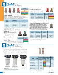
TEEJETTEEJET8001-SS8001-HSSsprayangletipcapacity visiflo ®ceramicvKvisiflostainlesssteelvsstainlesssteelSShardenedstainlesssteelHssHelpful Reminders for Band Spraying95º 015-08 •40º, 65º,80º, 95º01-15 • •Wider angle spray 80° Even Flat Spraytips allow the sprayheight to be loweredto minimize drift. 129(31 cm)Example:209 (50 cm)95° Even Flat Spray40º, 80º 02-06 • •99(23 cm)209 (50 cm)95º 015-08 •40º, 65º,80º, 95º01-15 • •40º, 80º 02-06 • •The spray angle ofthe nozzle and theresulting band widthare directly influencedby the sprayingpressure.Example: 8002E EvenFlat Spray129(31 cm)15 PSI (1 bar)159 (38 cm)45 PSI (3 bar)129(31 cm)85º 02-04 •TXA &TXB 80ºTX 80ºTXA &TXB 80º0050-041-260050-04•• • ••209 (50 cm)Use care when calculating:Field Acres/Hectares vs. Treated Acres/HectaresField Acres/Hectares = Total Acres/Hectaresof Planted CroplandTreated Acres/Hectares =Field Acres/Hectares X Band WidthRow SpacingTX 80º1-26• • •13º-114º 1-16 • • •BroadcastBandingSELECTION GUIDE5
TEEJETdriftmanagementsprayangletipcapacitIES visiflo ®polymervpvisifloceramicvKvisiflostainlesssteelVS8001-SSstainlesssteelssvery GOOD110º 01–08 •very GOODvery GOOD110º 02–06 •EXCELLENTEXCELLENT 110º 015–06 •GOODxr 80º,xr 110º01–15 110º • • •very GOODxrC 80º,XRC 110º015–08 110º • •EXCELLENT 110º 015–06 •EXCELLENTAI 110ºAIC 110º015–08015–10 • •••65º, 80º, 110º 01–10 •very GOOD 110º 015–08 •very GOOD110º 01–08 •EXCELLENTEXCELLENT 140º– 150º 02–10 • •EXCELLENT 140º–150º 02–15 • •SELECTION GUIDE7
Liquid Fertilizer Nozzle Selection GuideTEEJETbroadcastdirectedsprayangletipcapacitIES visiflo ®polymervpvisifloceramicvKvisiflostainlesssteelVS8001-SSstainlesssteelssReference page 23EXCELLENT 140º–150º2-10 • •Reference page 25EXCELLENT 150º 15-120 •Reference page 24EXCELLENT 140º–150º02-15 • •(3-ORIFICE)Reference page 48very GOOD EXCELLENT — 015-20 •(7-ORIFICE)Reference page 49EXCELLENT very GOOD — 015-15 •Reference page 51EXCELLENT 0º 0004-0060 •(LARGE CAPACITY)Reference page 20very GOOD0º, 65º,80º, 110º0067-20 • •(LOW VOLUME)Reference pages 15–16very GOODAI 110ºAIC 110º015-08015-10 • •••Reference page 14GOOD 110º 015-06 •Reference page 11EXCELLENT 110º 015-06 •(LOW VOLUME)Reference page 41very GOOD 85º 02-04 •Note: Consult the chemical manufacturer’s product label for specific rate and application recommendations.8SELECTION GUIDE
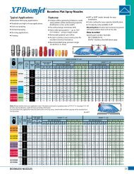
Wide Angle Flat Spray TipsTypical Applications:See selection guide on pages 2 and 6for recommended typical applicationsfor Turbo <strong>TeeJet</strong> tips.Features:n Tapered edge wide angle flat spray patternfor uniform coverage in broadcast spraying.n Large, rounded internal passage tominimize clogging.n Excellent resistance to corrosive solutions.n Superior wear characteristics.n Larger droplets for less drift—15–90 PSI (1–6 bar).n Automatic spray alignment with 25612-*-NYRQuick <strong>TeeJet</strong>® cap and gasket. Reference page63 for more information.n Blockage-free passage means less clogging.n Unique internal configuration meanssubstantially longer wear life.TT11001(100)TT110015(100)TT11002(50)TT110025(50)TT11003(50)TT11004(50)TT11005(50)TT11006(50)TT11008(50)psiDropSizecapacityonenozzlein GPMcapacityonenozzleinoz./min.gpa209gallons per 1000 sq. ft.4 mph 5 mph 6 mph 8 mph 10 mph 12 mph 15 mph 20 mph 2 mph 3 mph 4 mph 5 mph15 C 0.061 7.8 4.5 3.6 3.0 2.3 1.8 1.5 1.2 0.91 0.21 0.14 0.10 0.0820 M 0.071 9.1 5.3 4.2 3.5 2.6 2.1 1.8 1.4 1.1 0.24 0.16 0.12 0.1030 M 0.087 11 6.5 5.2 4.3 3.2 2.6 2.2 1.7 1.3 0.30 0.20 0.15 0.1240 M 0.10 13 7.4 5.9 5.0 3.7 3.0 2.5 2.0 1.5 0.34 0.23 0.17 0.1450 F 0.11 14 8.2 6.5 5.4 4.1 3.3 2.7 2.2 1.6 0.37 0.25 0.19 0.1560 F 0.12 15 8.9 7.1 5.9 4.5 3.6 3.0 2.4 1.8 0.41 0.27 0.20 0.1675 F 0.14 18 10.4 8.3 6.9 5.2 4.2 3.5 2.8 2.1 0.48 0.32 0.24 0.1990 F 0.15 19 11.1 8.9 7.4 5.6 4.5 3.7 3.0 2.2 0.51 0.34 0.26 0.2015 C 0.092 12 6.8 5.5 4.6 3.4 2.7 2.3 1.8 1.4 0.31 0.21 0.16 0.1320 C 0.11 14 8.2 6.5 5.4 4.1 3.3 2.7 2.2 1.6 0.37 0.25 0.19 0.1530 M 0.13 17 9.7 7.7 6.4 4.8 3.9 3.2 2.6 1.9 0.44 0.29 0.22 0.1840 M 0.15 19 11.1 8.9 7.4 5.6 4.5 3.7 3.0 2.2 0.51 0.34 0.26 0.2050 M 0.17 22 12.6 10.1 8.4 6.3 5.0 4.2 3.4 2.5 0.58 0.39 0.29 0.2360 M 0.18 23 13.4 10.7 8.9 6.7 5.3 4.5 3.6 2.7 0.61 0.41 0.31 0.2475 F 0.21 27 15.6 12.5 10.4 7.8 6.2 5.2 4.2 3.1 0.71 0.48 0.36 0.2990 F 0.23 29 17.1 13.7 11.4 8.5 6.8 5.7 4.6 3.4 0.78 0.52 0.39 0.3115 C 0.12 15 8.9 7.1 5.9 4.5 3.6 3.0 2.4 1.8 0.41 0.27 0.20 0.1620 C 0.14 18 10.4 8.3 6.9 5.2 4.2 3.5 2.8 2.1 0.48 0.32 0.24 0.1930 M 0.17 22 12.6 10.1 8.4 6.3 5.0 4.2 3.4 2.5 0.58 0.39 0.29 0.2340 M 0.20 26 14.9 11.9 9.9 7.4 5.9 5.0 4.0 3.0 0.68 0.45 0.34 0.2750 M 0.22 28 16.3 13.1 10.9 8.2 6.5 5.4 4.4 3.3 0.75 0.50 0.37 0.3060 M 0.24 31 17.8 14.3 11.9 8.9 7.1 5.9 4.8 3.6 0.82 0.54 0.41 0.3375 M 0.27 35 20 16.0 13.4 10.0 8.0 6.7 5.3 4.0 0.92 0.61 0.46 0.3790 F 0.30 38 22 17.8 14.9 11.1 8.9 7.4 5.9 4.5 1.0 0.68 0.51 0.4115 VC 0.15 19 11.1 8.9 7.4 5.6 4.5 3.7 3.0 2.2 0.51 0.34 0.26 0.2020 C 0.18 23 13.4 10.7 8.9 6.7 5.3 4.5 3.6 2.7 0.61 0.41 0.31 0.2430 C 0.22 28 16.3 13.1 10.9 8.2 6.5 5.4 4.4 3.3 0.75 0.50 0.37 0.3040 M 0.25 32 18.6 14.9 12.4 9.3 7.4 6.2 5.0 3.7 0.85 0.57 0.43 0.3450 M 0.28 36 21 16.6 13.9 10.4 8.3 6.9 5.5 4.2 0.95 0.63 0.48 0.3860 M 0.31 40 23 18.4 15.3 11.5 9.2 7.7 6.1 4.6 1.1 0.70 0.53 0.4275 M 0.34 44 25 20 16.8 12.6 10.1 8.4 6.7 5.0 1.2 0.77 0.58 0.4690 F 0.38 49 28 23 18.8 14.1 11.3 9.4 7.5 5.6 1.3 0.86 0.65 0.5215 VC 0.18 23 13.4 10.7 8.9 6.7 5.3 4.5 3.6 2.7 0.61 0.41 0.31 0.2420 VC 0.21 27 15.6 12.5 10.4 7.8 6.2 5.2 4.2 3.1 0.71 0.48 0.36 0.2930 C 0.26 33 19.3 15.4 12.9 9.7 7.7 6.4 5.1 3.9 0.88 0.59 0.44 0.3540 C 0.30 38 22 17.8 14.9 11.1 8.9 7.4 5.9 4.5 1.0 0.68 0.51 0.4150 M 0.34 44 25 20 16.8 12.6 10.1 8.4 6.7 5.0 1.2 0.77 0.58 0.4660 M 0.37 47 27 22 18.3 13.7 11.0 9.2 7.3 5.5 1.3 0.84 0.63 0.5075 M 0.41 52 30 24 20 15.2 12.2 10.1 8.1 6.1 1.4 0.93 0.70 0.5690 M 0.45 58 33 27 22 16.7 13.4 11.1 8.9 6.7 1.5 1.0 0.77 0.6115 XC 0.24 31 17.8 14.3 11.9 8.9 7.1 5.9 4.8 3.6 0.82 0.54 0.41 0.3320 VC 0.28 36 21 16.6 13.9 10.4 8.3 6.9 5.5 4.2 0.95 0.63 0.48 0.3830 C 0.35 45 26 21 17.3 13.0 10.4 8.7 6.9 5.2 1.2 0.79 0.60 0.4840 C 0.40 51 30 24 19.8 14.9 11.9 9.9 7.9 5.9 1.4 0.91 0.68 0.5450 C 0.45 58 33 27 22 16.7 13.4 11.1 8.9 6.7 1.5 1.0 0.77 0.6160 C 0.49 63 36 29 24 18.2 14.6 12.1 9.7 7.3 1.7 1.1 0.83 0.6775 M 0.55 70 41 33 27 20 16.3 13.6 10.9 8.2 1.9 1.2 0.94 0.7590 M 0.60 77 45 36 30 22 17.8 14.9 11.9 8.9 2.0 1.4 1.0 0.8215 XC 0.31 40 23 18.4 15.3 11.5 9.2 7.7 6.1 4.6 1.1 0.70 0.53 0.4220 VC 0.35 45 26 21 17.3 13.0 10.4 8.7 6.9 5.2 1.2 0.79 0.60 0.4830 VC 0.43 55 32 26 21 16.0 12.8 10.6 8.5 6.4 1.5 0.97 0.73 0.5840 C 0.50 64 37 30 25 18.6 14.9 12.4 9.9 7.4 1.7 1.1 0.85 0.6850 C 0.56 72 42 33 28 21 16.6 13.9 11.1 8.3 1.9 1.3 0.95 0.7660 C 0.61 78 45 36 30 23 18.1 15.1 12.1 9.1 2.1 1.4 1.0 0.8375 C 0.68 87 50 40 34 25 20 16.8 13.5 10.1 2.3 1.5 1.2 0.9290 M 0.75 96 56 45 37 28 22 18.6 14.9 11.1 2.6 1.7 1.3 1.015 XC 0.37 47 27 22 18.3 13.7 11.0 9.2 7.3 5.5 1.3 0.84 0.63 0.5020 XC 0.42 54 31 25 21 15.6 12.5 10.4 8.3 6.2 1.4 0.95 0.71 0.5730 VC 0.52 67 39 31 26 19.3 15.4 12.9 10.3 7.7 1.8 1.2 0.88 0.7140 C 0.60 77 45 36 30 22 17.8 14.9 11.9 8.9 2.0 1.4 1.0 0.8250 C 0.67 86 50 40 33 25 19.9 16.6 13.3 9.9 2.3 1.5 1.1 0.9160 C 0.73 93 54 43 36 27 22 18.1 14.5 10.8 2.5 1.7 1.2 0.9975 C 0.82 105 61 49 41 30 24 20 16.2 12.2 2.8 1.9 1.4 1.190 M 0.90 115 67 53 45 33 27 22 17.8 13.4 3.1 2.0 1.5 1.215 XC 0.49 63 36 29 24 18.2 14.6 12.1 9.7 7.3 1.7 1.1 0.83 0.6720 XC 0.57 73 42 34 28 21 16.9 14.1 11.3 8.5 1.9 1.3 0.97 0.7830 VC 0.69 88 51 41 34 26 20 17.1 13.7 10.2 2.3 1.6 1.2 0.9440 VC 0.80 102 59 48 40 30 24 19.8 15.8 11.9 2.7 1.8 1.4 1.150 C 0.89 114 66 53 44 33 26 22 17.6 13.2 3.0 2.0 1.5 1.260 C 0.98 125 73 58 49 36 29 24 19.4 14.6 3.3 2.2 1.7 1.375 C 1.10 141 82 65 54 41 33 27 22 16.3 3.7 2.5 1.9 1.590 M 1.20 154 89 71 59 45 36 30 24 17.8 4.1 2.7 2.0 1.6Note: Always double check your application rates.Tabulations are based on spraying water at 70°F (21°C).VeryFineFine Medium Coarse VeryCoarseExtremelyCoarseCONTACTProductSpacing110°SYSTEMICProductOptimum Spray HeightDRIFTManagementVery Good Very Good Very GoodGood* EXCELLENT* Very Good**At pressures below 30 PSI (2.0 bar)209209See pages 173–187 for drop size classification,useful formulas and information.How to order:Specify tip number.Example:TT11001-VP – Polymer with VisiFlo®color-codingSprayHeightBROADCAST NOZZLES9 9
Twin Flat Spray TipsTypical Applications:See selection guide on pages 2 and 6for recommended typical applicationsfor Turbo TwinJet tips.Features:n Dual outlet design produces two 110°flat fan spray patterns using the patentedtechnology from the Turbo <strong>TeeJet</strong>® nozzle.The angle between each spray pattern is60° forward and back.n Best suited for broadcast spraying wheresuperior leaf coverage and canopypenetration is important.n Droplet size range is slightly larger thanfor the same capacity Turbo <strong>TeeJet</strong> nozzleproviding drift-reducing properties withincreased canopy coverage and penetration.n Molded polymer for excellent chemicaland wear resistance.n Available in six VisiFlo® color-codedcapacities with pressure ranges from20–90 PSI (1.5–6 bar).n Ideal for use with automatic sprayercontrollers.n Automatic alignment when used with25612-*-NYR Quick <strong>TeeJet</strong>® cap and gasket.See page 63 for additional information.TTJ60-11002(100)TTJ60-110025(100)TTJ60-11003(100)TTJ60-11004(50)TTJ60-11005(50)TTJ60-11006(50)psiDropSizecapacityonenozzlein GPMcapacityonenozzleinoz./min.gpa209gallons per 1000 sq. ft.4 mph 5 mph 6 mph 8 mph 10 mph 12 mph 15 mph 20 mph 2 mph 3 mph 4 mph 5 mph2030CC0.140.17182210.412.68.310.16.98.45.26.34.25.03.54.22.83.42.12.50.480.580.320.390.240.290.190.2340 C 0.20 26 14.9 11.9 9.9 7.4 5.9 5.0 4.0 3.0 0.68 0.45 0.34 0.2750 M 0.22 28 16.3 13.1 10.9 8.2 6.5 5.4 4.4 3.3 0.75 0.50 0.37 0.3060 M 0.24 31 17.8 14.3 11.9 8.9 7.1 5.9 4.8 3.6 0.82 0.54 0.41 0.3370 M 0.26 33 19.3 15.4 12.9 9.7 7.7 6.4 5.1 3.9 0.88 0.59 0.44 0.3580 M 0.28 36 21 16.6 13.9 10.4 8.3 6.9 5.5 4.2 0.95 0.63 0.48 0.3890 M 0.30 38 22 17.8 14.9 11.1 8.9 7.4 5.9 4.5 1.0 0.68 0.51 0.4120 VC 0.18 23 13.4 10.7 8.9 6.7 5.3 4.5 3.6 2.7 0.61 0.41 0.31 0.2430 C 0.22 28 16.3 13.1 10.9 8.2 6.5 5.4 4.4 3.3 0.75 0.50 0.37 0.3040 C 0.25 32 18.6 14.9 12.4 9.3 7.4 6.2 5.0 3.7 0.85 0.57 0.43 0.3450 C 0.28 36 21 16.6 13.9 10.4 8.3 6.9 5.5 4.2 0.95 0.63 0.48 0.3860 C 0.31 40 23 18.4 15.3 11.5 9.2 7.7 6.1 4.6 1.1 0.70 0.53 0.4270 M 0.33 42 25 19.6 16.3 12.3 9.8 8.2 6.5 4.9 1.1 0.75 0.56 0.4580 M 0.35 45 26 21 17.3 13.0 10.4 8.7 6.9 5.2 1.2 0.79 0.60 0.4890 M 0.38 49 28 23 18.8 14.1 11.3 9.4 7.5 5.6 1.3 0.86 0.65 0.5220 VC 0.21 27 15.6 12.5 10.4 7.8 6.2 5.2 4.2 3.1 0.71 0.48 0.36 0.2930 C 0.26 33 19.3 15.4 12.9 9.7 7.7 6.4 5.1 3.9 0.88 0.59 0.44 0.3540 C 0.30 38 22 17.8 14.9 11.1 8.9 7.4 5.9 4.5 1.0 0.68 0.51 0.4150 C 0.34 44 25 20 16.8 12.6 10.1 8.4 6.7 5.0 1.2 0.77 0.58 0.4660 C 0.37 47 27 22 18.3 13.7 11.0 9.2 7.3 5.5 1.3 0.84 0.63 0.5070 C 0.40 51 30 24 19.8 14.9 11.9 9.9 7.9 5.9 1.4 0.91 0.68 0.5480 M 0.42 54 31 25 21 15.6 12.5 10.4 8.3 6.2 1.4 0.95 0.71 0.5790 M 0.45 58 33 27 22 16.7 13.4 11.1 8.9 6.7 1.5 1.0 0.77 0.6120 VC 0.28 36 21 16.6 13.9 10.4 8.3 6.9 5.5 4.2 0.95 0.63 0.48 0.3830 C 0.35 45 26 21 17.3 13.0 10.4 8.7 6.9 5.2 1.2 0.79 0.60 0.4840 C 0.40 51 30 24 19.8 14.9 11.9 9.9 7.9 5.9 1.4 0.91 0.68 0.5450 C 0.45 58 33 27 22 16.7 13.4 11.1 8.9 6.7 1.5 1.0 0.77 0.6160 C 0.49 63 36 29 24 18.2 14.6 12.1 9.7 7.3 1.7 1.1 0.83 0.6770 C 0.53 68 39 31 26 19.7 15.7 13.1 10.5 7.9 1.8 1.2 0.90 0.7280 C 0.57 73 42 34 28 21 16.9 14.1 11.3 8.5 1.9 1.3 0.97 0.7890 M 0.60 77 45 36 30 22 17.8 14.9 11.9 8.9 2.0 1.4 1.0 0.8220 VC 0.35 45 26 21 17.3 13.0 10.4 8.7 6.9 5.2 1.2 0.79 0.60 0.4830 C 0.43 55 32 26 21 16.0 12.8 10.6 8.5 6.4 1.5 0.97 0.73 0.5840 C 0.50 64 37 30 25 18.6 14.9 12.4 9.9 7.4 1.7 1.1 0.85 0.6850 C 0.56 72 42 33 28 21 16.6 13.9 11.1 8.3 1.9 1.3 0.95 0.7660 C 0.61 78 45 36 30 23 18.1 15.1 12.1 9.1 2.1 1.4 1.0 0.8370 C 0.66 84 49 39 33 25 19.6 16.3 13.1 9.8 2.2 1.5 1.1 0.9080 C 0.71 91 53 42 35 26 21 17.6 14.1 10.5 2.4 1.6 1.2 0.9790 C 0.75 96 56 45 37 28 22 18.6 14.9 11.1 2.6 1.7 1.3 1.020 XC 0.42 54 31 25 21 15.6 12.5 10.4 8.3 6.2 1.4 0.95 0.71 0.5730 VC 0.52 67 39 31 26 19.3 15.4 12.9 10.3 7.7 1.8 1.2 0.88 0.7140 C 0.60 77 45 36 30 22 17.8 14.9 11.9 8.9 2.0 1.4 1.0 0.8250 C 0.67 86 50 40 33 25 19.9 16.6 13.3 9.9 2.3 1.5 1.1 0.9160 C 0.73 93 54 43 36 27 22 18.1 14.5 10.8 2.5 1.7 1.2 0.9970 C 0.79 101 59 47 39 29 23 19.6 15.6 11.7 2.7 1.8 1.3 1.180 C 0.85 109 63 50 42 32 25 21 16.8 12.6 2.9 1.9 1.4 1.290 C 0.90 115 67 53 45 33 27 22 17.8 13.4 3.1 2.0 1.5 1.2Note: Always double check your application rates.Tabulations are based on spraying water at 70°F (21°C).VeryFineFine Medium Coarse VeryCoarseExtremelyCoarseCONTACTProduct60°TTJ60-110___VP Spray Tip(Cross Section View)SpacingOptimum Spray Height110°SYSTEMICProductDRIFTManagementEXCELLENT EXCELLENT Very GoodVery Good* EXCELLENT* EXCELLENT**At pressures below 30 PSI (2.0 bar)209209See pages 173–187 for drop size classification,useful formulas and information.SprayHeightHow to order:Specify tip number.Example:TTJ60-11004VP – Polymer with VisiFlo®color-coding10BROADCAST NOZZLES
Flat Spray TipsTypical Applications:See selection guide on pages 2 and 6for recommended typical applicationsfor Turbo <strong>TeeJet</strong> Induction tips.Features:n 110° wide angle, air induction, tapered flatspray tip pattern based on the patentedoutlet orifice design of the original Turbo<strong>TeeJet</strong>® nozzle.n Patented orifice design provides large,round passages to minimize plugging.n Depending on the chemical, produceslarge air-filled drops through a Venturiair aspirator resulting in less drift.n <strong>All</strong> polymer construction for excellentchemical and wear resistance.n Compact size to prevent tip damage.n Removable pre-orifice.n Ideal for use with automatic sprayercontrollers.RemovableInsertPre-OrificeMixingChamberTwo internalair inletsOne externalair inletExit Orifice with15° offset fromvertical positionTTI110___-VP Spray Tip(Cross Section View)Note: Due to pre-orifice design, this tip is not compatiblewith the 4193A check valve tip strainer.n Wide operating pressure range:15–100 PSI (1–7 bar).n Automatic alignment when used with25598-*-NYR Quick <strong>TeeJet</strong>® cap and gasket.See page 63 for additional information.TTI110015(100)TTI11002(50)TTI110025(50)TTI11003(50)TTI11004(50)TTI11005(50)TTI11006(50)psiDropSizecapacityonenozzlein GPMcapacityonenozzleinoz./min.gpa209gallons per 1000 sq. ft.4 mph 5 mph 6 mph 8 mph 10 mph 12 mph 15 mph 20 mph 2 mph 3 mph 4 mph 5 mph15 XC 0.092 12 6.8 5.5 4.6 3.4 2.7 2.3 1.8 1.4 0.31 0.21 0.16 0.1320 XC 0.11 14 8.2 6.5 5.4 4.1 3.3 2.7 2.2 1.6 0.37 0.25 0.19 0.1530 XC 0.13 17 9.7 7.7 6.4 4.8 3.9 3.2 2.6 1.9 0.44 0.29 0.22 0.1840 XC 0.15 19 11.1 8.9 7.4 5.6 4.5 3.7 3.0 2.2 0.51 0.34 0.26 0.2050 XC 0.17 22 12.6 10.1 8.4 6.3 5.0 4.2 3.4 2.5 0.58 0.39 0.29 0.2360 XC 0.18 23 13.4 10.7 8.9 6.7 5.3 4.5 3.6 2.7 0.61 0.41 0.31 0.2470 XC 0.20 26 14.9 11.9 9.9 7.4 5.9 5.0 4.0 3.0 0.68 0.45 0.34 0.2780 XC 0.21 27 15.6 12.5 10.4 7.8 6.2 5.2 4.2 3.1 0.71 0.48 0.36 0.2990 XC 0.23 29 17.1 13.7 11.4 8.5 6.8 5.7 4.6 3.4 0.78 0.52 0.39 0.31100 XC 0.24 31 17.8 14.3 11.9 8.9 7.1 5.9 4.8 3.6 0.82 0.54 0.41 0.3315 XC 0.12 15 8.9 7.1 5.9 4.5 3.6 3.0 2.4 1.8 0.41 0.27 0.20 0.1620 XC 0.14 18 10.4 8.3 6.9 5.2 4.2 3.5 2.8 2.1 0.48 0.32 0.24 0.1930 XC 0.17 22 12.6 10.1 8.4 6.3 5.0 4.2 3.4 2.5 0.58 0.39 0.29 0.2340 XC 0.20 26 14.9 11.9 9.9 7.4 5.9 5.0 4.0 3.0 0.68 0.45 0.34 0.2750 XC 0.22 28 16.3 13.1 10.9 8.2 6.5 5.4 4.4 3.3 0.75 0.50 0.37 0.3060 XC 0.24 31 17.8 14.3 11.9 8.9 7.1 5.9 4.8 3.6 0.82 0.54 0.41 0.3370 XC 0.26 33 19.3 15.4 12.9 9.7 7.7 6.4 5.1 3.9 0.88 0.59 0.44 0.3580 XC 0.28 36 21 16.6 13.9 10.4 8.3 6.9 5.5 4.2 0.95 0.63 0.48 0.3890 XC 0.30 38 22 17.8 14.9 11.1 8.9 7.4 5.9 4.5 1.0 0.68 0.51 0.41100 XC 0.32 41 24 19.0 15.8 11.9 9.5 7.9 6.3 4.8 1.1 0.73 0.54 0.4415 XC 0.15 19 11.1 8.9 7.4 5.6 4.5 3.7 3.0 2.2 0.51 0.34 0.26 0.2020 XC 0.18 23 13.4 10.7 8.9 6.7 5.3 4.5 3.6 2.7 0.61 0.41 0.31 0.2430 XC 0.22 28 16.3 13.1 10.9 8.2 6.5 5.4 4.4 3.3 0.75 0.50 0.37 0.3040 XC 0.25 32 18.6 14.9 12.4 9.3 7.4 6.2 5.0 3.7 0.85 0.57 0.43 0.3450 XC 0.28 36 21 16.6 13.9 10.4 8.3 6.9 5.5 4.2 0.95 0.63 0.48 0.3860 XC 0.31 40 23 18.4 15.3 11.5 9.2 7.7 6.1 4.6 1.1 0.70 0.53 0.4270 XC 0.33 42 25 19.6 16.3 12.3 9.8 8.2 6.5 4.9 1.1 0.75 0.56 0.4580 XC 0.35 45 26 21 17.3 13.0 10.4 8.7 6.9 5.2 1.2 0.79 0.60 0.4890 XC 0.38 49 28 23 18.8 14.1 11.3 9.4 7.5 5.6 1.3 0.86 0.65 0.52100 XC 0.40 51 30 24 19.8 14.9 11.9 9.9 7.9 5.9 1.4 0.91 0.68 0.5415 XC 0.18 23 13.4 10.7 8.9 6.7 5.3 4.5 3.6 2.7 0.61 0.41 0.31 0.2420 XC 0.21 27 15.6 12.5 10.4 7.8 6.2 5.2 4.2 3.1 0.71 0.48 0.36 0.2930 XC 0.26 33 19.3 15.4 12.9 9.7 7.7 6.4 5.1 3.9 0.88 0.59 0.44 0.3540 XC 0.30 38 22 17.8 14.9 11.1 8.9 7.4 5.9 4.5 1.0 0.68 0.51 0.4150 XC 0.34 44 25 20 16.8 12.6 10.1 8.4 6.7 5.0 1.2 0.77 0.58 0.4660 XC 0.37 47 27 22 18.3 13.7 11.0 9.2 7.3 5.5 1.3 0.84 0.63 0.5070 XC 0.40 51 30 24 19.8 14.9 11.9 9.9 7.9 5.9 1.4 0.91 0.68 0.5480 XC 0.42 54 31 25 21 15.6 12.5 10.4 8.3 6.2 1.4 0.95 0.71 0.5790 XC 0.45 58 33 27 22 16.7 13.4 11.1 8.9 6.7 1.5 1.0 0.77 0.61100 XC 0.47 60 35 28 23 17.4 14.0 11.6 9.3 7.0 1.6 1.1 0.80 0.6415 XC 0.24 31 17.8 14.3 11.9 8.9 7.1 5.9 4.8 3.6 0.82 0.54 0.41 0.3320 XC 0.28 36 21 16.6 13.9 10.4 8.3 6.9 5.5 4.2 0.95 0.63 0.48 0.3830 XC 0.35 45 26 21 17.3 13.0 10.4 8.7 6.9 5.2 1.2 0.79 0.60 0.4840 XC 0.40 51 30 24 19.8 14.9 11.9 9.9 7.9 5.9 1.4 0.91 0.68 0.5450 XC 0.45 58 33 27 22 16.7 13.4 11.1 8.9 6.7 1.5 1.0 0.77 0.6160 XC 0.49 63 36 29 24 18.2 14.6 12.1 9.7 7.3 1.7 1.1 0.83 0.6770 XC 0.53 68 39 31 26 19.7 15.7 13.1 10.5 7.9 1.8 1.2 0.90 0.7280 XC 0.57 73 42 34 28 21 16.9 14.1 11.3 8.5 1.9 1.3 0.97 0.7890 XC 0.60 77 45 36 30 22 17.8 14.9 11.9 8.9 2.0 1.4 1.0 0.82100 XC 0.63 81 47 37 31 23 18.7 15.6 12.5 9.4 2.1 1.4 1.1 0.8615 XC 0.31 40 23 18.4 15.3 11.5 9.2 7.7 6.1 4.6 1.1 0.70 0.53 0.4220 XC 0.35 45 26 21 17.3 13.0 10.4 8.7 6.9 5.2 1.2 0.79 0.60 0.4830 XC 0.43 55 32 26 21 16.0 12.8 10.6 8.5 6.4 1.5 0.97 0.73 0.5840 XC 0.50 64 37 30 25 18.6 14.9 12.4 9.9 7.4 1.7 1.1 0.85 0.6850 XC 0.56 72 42 33 28 21 16.6 13.9 11.1 8.3 1.9 1.3 0.95 0.7660 XC 0.61 78 45 36 30 23 18.1 15.1 12.1 9.1 2.1 1.4 1.0 0.8370 XC 0.66 84 49 39 33 25 19.6 16.3 13.1 9.8 2.2 1.5 1.1 0.9080 XC 0.71 91 53 42 35 26 21 17.6 14.1 10.5 2.4 1.6 1.2 0.9790 XC 0.75 96 56 45 37 28 22 18.6 14.9 11.1 2.6 1.7 1.3 1.0100 XC 0.79 101 59 47 39 29 23 19.6 15.6 11.7 2.7 1.8 1.3 1.115 XC 0.37 47 27 22 18.3 13.7 11.0 9.2 7.3 5.5 1.3 0.84 0.63 0.5020 XC 0.42 54 31 25 21 15.6 12.5 10.4 8.3 6.2 1.4 0.95 0.71 0.5730 XC 0.52 67 39 31 26 19.3 15.4 12.9 10.3 7.7 1.8 1.2 0.88 0.7140 XC 0.60 77 45 36 30 22 17.8 14.9 11.9 8.9 2.0 1.4 1.0 0.8250 XC 0.67 86 50 40 33 25 19.9 16.6 13.3 9.9 2.3 1.5 1.1 0.9160 XC 0.73 93 54 43 36 27 22 18.1 14.5 10.8 2.5 1.7 1.2 0.9970 XC 0.79 101 59 47 39 29 23 19.6 15.6 11.7 2.7 1.8 1.3 1.180 XC 0.85 109 63 50 42 32 25 21 16.8 12.6 2.9 1.9 1.4 1.290 XC 0.90 115 67 53 45 33 27 22 17.8 13.4 3.1 2.0 1.5 1.2100 XC 0.95 122 71 56 47 35 28 24 18.8 14.1 3.2 2.2 1.6 1.3Note: Always double check your application rates.Tabulations are based on spraying water at 70°F (21°C).VeryFineFine Medium Coarse VeryCoarseExtremelyCoarseCONTACTProductSpacing110°SYSTEMICProductOptimum Spray HeightDRIFTManagement— EXCELLENT EXCELLENT209209See pages 173–187 for drop size classification,useful formulas and information.SprayHeightHow to order:Specify tip number.Example:TTI11004-VP – Polymer with VisiFlo®color-codingBROADCAST NOZZLES11 11
Extended Range Flat Spray TipsTypical Applications:See selection guide on pages 2 and 6for recommended typical applicationsfor XR <strong>TeeJet</strong> tips.Features:n Excellent spray distribution over a widerange of pressures—15–60 PSI (1–4 bar).n Ideal for rigs equipped with sprayercontrollers.n Reduces drift at lower pressures, bettercoverage at higher pressures.n Available in stainless steel, ceramic andpolymer in 80° and 110° spray angles withVisiFlo® color-coding.n Ceramic is available with corrosiveresistantpolypropylene VisiFlo colorcodedtip holder in 80° capacities 03– 08and 110° capacities 02–08.n Brass available in 110° only.n Automatic spray alignment with25612-*-NYR Quick <strong>TeeJet</strong>® cap and gasket.Reference page 63 for more information.n Automatic spray alignment for sizes 10and 15 with 25610-*-NYR Quick <strong>TeeJet</strong>cap and gasket. Reference page 63 formore information.At 15 PSI (1 bar)PressureAt 60 PSI (4 bar)PressureXR8001XR11001(100)XR80015XR110015(100)XR8002XR11002(50)XR110025(50)XR8003XR11003(50)XR8004XR11004(50)XR8005XR11005(50)XR8006XR11006(50)XR8008XR11008(50)XR8010†XR11010†XR8015†XR11015†capacityDrop capacity209oneSize onenozzlenozzlepsiingpagallons per 1000 sq. ft.in GPM80º 110º oz./min. 4 mph 5 mph 6 mph 8 mph 10 mph 12 mph 15 mph 20 mph 2 mph 3 mph 4 mph 5 mph1520MFFF0.0610.0717.89.14.55.33.64.23.03.52.32.61.82.11.51.81.21.40.911.10.210.240.140.160.100.120.080.1030 F F 0.087 11 6.5 5.2 4.3 3.2 2.6 2.2 1.7 1.3 0.30 0.20 0.15 0.1240 F F 0.10 13 7.4 5.9 5.0 3.7 3.0 2.5 2.0 1.5 0.34 0.23 0.17 0.1450 F VF 0.11 14 8.2 6.5 5.4 4.1 3.3 2.7 2.2 1.6 0.37 0.25 0.19 0.1560 F VF 0.12 15 8.9 7.1 5.9 4.5 3.6 3.0 2.4 1.8 0.41 0.27 0.20 0.1615 M F 0.092 12 6.8 5.5 4.6 3.4 2.7 2.3 1.8 1.4 0.31 0.21 0.16 0.1320 M F 0.11 14 8.2 6.5 5.4 4.1 3.3 2.7 2.2 1.6 0.37 0.25 0.19 0.1530 F F 0.13 17 9.7 7.7 6.4 4.8 3.9 3.2 2.6 1.9 0.44 0.29 0.22 0.1840 F F 0.15 19 11.1 8.9 7.4 5.6 4.5 3.7 3.0 2.2 0.51 0.34 0.26 0.2050 F F 0.17 22 12.6 10.1 8.4 6.3 5.0 4.2 3.4 2.5 0.58 0.39 0.29 0.2360 F F 0.18 23 13.4 10.7 8.9 6.7 5.3 4.5 3.6 2.7 0.61 0.41 0.31 0.2415 M M 0.12 15 8.9 7.1 5.9 4.5 3.6 3.0 2.4 1.8 0.41 0.27 0.20 0.1620 M F 0.14 18 10.4 8.3 6.9 5.2 4.2 3.5 2.8 2.1 0.48 0.32 0.24 0.1930 M F 0.17 22 12.6 10.1 8.4 6.3 5.0 4.2 3.4 2.5 0.58 0.39 0.29 0.2340 F F 0.20 26 14.9 11.9 9.9 7.4 5.9 5.0 4.0 3.0 0.68 0.45 0.34 0.2750 F F 0.22 28 16.3 13.1 10.9 8.2 6.5 5.4 4.4 3.3 0.75 0.50 0.37 0.3060 F F 0.24 31 17.8 14.3 11.9 8.9 7.1 5.9 4.8 3.6 0.82 0.54 0.41 0.3315 M 0.15 19 11.1 8.9 7.4 5.6 4.5 3.7 3.0 2.2 0.51 0.34 0.26 0.2020 M 0.18 23 13.4 10.7 8.9 6.7 5.3 4.5 3.6 2.7 0.61 0.41 0.31 0.2430 F 0.22 28 16.3 13.1 10.9 8.2 6.5 5.4 4.4 3.3 0.75 0.50 0.37 0.3040 F 0.25 32 18.6 14.9 12.4 9.3 7.4 6.2 5.0 3.7 0.85 0.57 0.43 0.3450 F 0.28 36 21 16.6 13.9 10.4 8.3 6.9 5.5 4.2 0.95 0.63 0.48 0.3860 F 0.31 40 23 18.4 15.3 11.5 9.2 7.7 6.1 4.6 1.1 0.70 0.53 0.4215 M M 0.18 23 13.4 10.7 8.9 6.7 5.3 4.5 3.6 2.7 0.61 0.41 0.31 0.2420 M M 0.21 27 15.6 12.5 10.4 7.8 6.2 5.2 4.2 3.1 0.71 0.48 0.36 0.2930 M F 0.26 33 19.3 15.4 12.9 9.7 7.7 6.4 5.1 3.9 0.88 0.59 0.44 0.3540 M F 0.30 38 22 17.8 14.9 11.1 8.9 7.4 5.9 4.5 1.0 0.68 0.51 0.4150 M F 0.34 44 25 20 16.8 12.6 10.1 8.4 6.7 5.0 1.2 0.77 0.58 0.4660 F F 0.37 47 27 22 18.3 13.7 11.0 9.2 7.3 5.5 1.3 0.84 0.63 0.5015 C M 0.24 31 17.8 14.3 11.9 8.9 7.1 5.9 4.8 3.6 0.82 0.54 0.41 0.3320 C M 0.28 36 21 16.6 13.9 10.4 8.3 6.9 5.5 4.2 1.0 0.63 0.48 0.3830 M M 0.35 45 26 21 17.3 13.0 10.4 8.7 6.9 5.2 1.2 0.79 0.60 0.4840 M M 0.40 51 30 24 19.8 14.9 11.9 9.9 7.9 5.9 1.4 0.91 0.68 0.5450 M F 0.45 58 33 27 22 16.7 13.4 11.1 8.9 6.7 1.5 1.0 0.77 0.6160 M F 0.49 63 36 29 24 18.2 14.6 12.1 9.7 7.3 1.7 1.1 0.83 0.6715 C M 0.31 40 23 18.4 15.3 11.5 9.2 7.7 6.1 4.6 1.1 0.70 0.53 0.4220 C M 0.35 45 26 21 17.3 13.0 10.4 8.7 6.9 5.2 1.2 0.79 0.60 0.4830 C M 0.43 55 32 26 21 16.0 12.8 10.6 8.5 6.4 1.5 0.97 0.73 0.5840 M M 0.50 64 37 30 25 18.6 14.9 12.4 9.9 7.4 1.7 1.1 0.85 0.6850 M M 0.56 72 42 33 28 21 16.6 13.9 11.1 8.3 1.9 1.3 0.95 0.7660 M F 0.61 78 45 36 30 23 18.1 15.1 12.1 9.1 2.1 1.4 1.0 0.8315 C C 0.37 47 27 22 18.3 13.7 11.0 9.2 7.3 5.5 1.3 0.84 0.63 0.5020 C C 0.42 54 31 25 21 15.6 12.5 10.4 8.3 6.2 1.4 1.0 0.71 0.5730 C M 0.52 67 39 31 26 19.3 15.4 12.9 10.3 7.7 1.8 1.2 0.88 0.7140 C M 0.60 77 45 36 30 22 17.8 14.9 11.9 8.9 2.0 1.4 1.0 0.8250 C M 0.67 86 50 40 33 25 19.9 16.6 13.3 9.9 2.3 1.5 1.1 0.9160 C M 0.73 93 54 43 36 27 22 18.1 14.5 10.8 2.5 1.7 1.2 0.9915 VC C 0.49 63 36 29 24 18.2 14.6 12.1 9.7 7.3 1.7 1.1 0.83 0.6720 VC C 0.57 73 42 34 28 21 16.9 14.1 11.3 8.5 1.9 1.3 0.97 0.7830 C C 0.69 88 51 41 34 26 20 17.1 13.7 10.2 2.3 1.6 1.2 0.9440 C C 0.80 102 59 48 40 30 24 19.8 15.8 11.9 2.7 1.8 1.4 1.150 C M 0.89 114 66 53 44 33 26 22 17.6 13.2 3.0 2.0 1.5 1.260 C M 0.98 125 73 58 49 36 29 24 19.4 14.6 3.3 2.2 1.7 1.315 0.61 78 45 36 30 23 18.1 15.1 12.1 9.1 2.1 1.4 1.0 0.8320 0.71 91 53 42 35 26 21 17.6 14.1 10.5 2.4 1.6 1.2 0.9730 0.87 111 65 52 43 32 26 22 17.2 12.9 3.0 2.0 1.5 1.240 1.00 128 74 59 50 37 30 25 19.8 14.9 3.4 2.3 1.7 1.450 1.12 143 83 67 55 42 33 28 22 16.6 3.8 2.5 1.9 1.560 1.22 156 91 72 60 45 36 30 24 18.1 4.1 2.8 2.1 1.715 0.92 118 68 55 46 34 27 23 18.2 13.7 3.1 2.1 1.6 1.320 1.06 136 79 63 52 39 31 26 21 15.7 3.6 2.4 1.8 1.430 1.30 166 97 77 64 48 39 32 26 19.3 4.4 2.9 2.2 1.840 1.50 192 111 89 74 56 45 37 30 22 5.1 3.4 2.6 2.050 1.68 215 125 100 83 62 50 42 33 25 5.7 3.8 2.9 2.360 1.84 236 137 109 91 68 55 46 36 27 6.3 4.2 3.1 2.5Note: Always double check your application rates.Tabulations are based on spraying water at 70°F (21°C).†Available in all stainless steel only.VeryFineFine Medium Coarse VeryCoarseExtremelyCoarseCONTACTProductSpacingOptimum Spray Height80°110°SYSTEMICProductDRIFTManagementEXCELLENT Good GoodGood* VERY GOOD* VERY GOOD**At pressures below 30 PSI (2.0 bar)209309209See pages 173–187 for drop size classification,useful formulas and information.SprayHeightHow to order:Specify tip number.Examples:XR8004VS – Stainless Steel withVisiFlo color-codingXR11004-VP – Polymer with VisiFlocolor-coding (110º only)XR11004-VK – Ceramic withpolypropyleneVisiFlo colorcodingXR8010SS – Stainless SteelXR11004VB – Brass with VisiFlocolor-coding(110° only)12BROADCAST NOZZLES
Extended Range Flat Spray TipsTypical Applications:See selection guide on pages 2 and 6 forrecommended typical applications for XRC<strong>TeeJet</strong> tips.Features:n Excellent spray distribution over a wide rangeof pressures—15–60 PSI (1–4 bar).n Ideal for rigs equipped with sprayer controllers.n Reduces drift at lower pressures, bettercoverage at higher pressures.XRC80015(100)XRC8002XRC11002(50)XRC110025(50)XRC8003XRC11003(50)XRC8004XRC11004(50)XRC8005XRC11005(50)XRC8006XRC11006(50)XRC8008XRC11008(50)XRC11010XRC11015XRC11020capacityDrop capacity209oneSize onenozzlenozzlepsiingpagallons per 1000 sq. ft.in GPM80º 110º oz./min. 4 mph 5 mph 6 mph 8 mph 10 mph 12 mph 15 mph 20 mph 2 mph 3 mph 4 mph 5 mph15 M 0.092 12 6.8 5.5 4.6 3.4 2.7 2.3 1.8 1.4 0.31 0.21 0.16 0.1320 M 0.11 14 8.2 6.5 5.4 4.1 3.3 2.7 2.2 1.6 0.37 0.25 0.19 0.1530 F 0.13 17 9.7 7.7 6.4 4.8 3.9 3.2 2.6 1.9 0.44 0.29 0.22 0.1840 F 0.15 19 11.1 8.9 7.4 5.6 4.5 3.7 3.0 2.2 0.51 0.34 0.26 0.2050 F 0.17 22 12.6 10.1 8.4 6.3 5.0 4.2 3.4 2.5 0.58 0.39 0.29 0.2360 F 0.18 23 13.4 10.7 8.9 6.7 5.3 4.5 3.6 2.7 0.61 0.41 0.31 0.2415 M M 0.12 15 8.9 7.1 5.9 4.5 3.6 3.0 2.4 1.8 0.41 0.27 0.20 0.1620 M F 0.14 18 10.4 8.3 6.9 5.2 4.2 3.5 2.8 2.1 0.48 0.32 0.24 0.1930 M F 0.17 22 12.6 10.1 8.4 6.3 5.0 4.2 3.4 2.5 0.58 0.39 0.29 0.2340 F F 0.20 26 14.9 11.9 9.9 7.4 5.9 5.0 4.0 3.0 0.68 0.45 0.34 0.2750 F F 0.22 28 16.3 13.1 10.9 8.2 6.5 5.4 4.4 3.3 0.75 0.50 0.37 0.3060 F F 0.24 31 17.8 14.3 11.9 8.9 7.1 5.9 4.8 3.6 0.82 0.54 0.41 0.3315 M 0.15 19 11.1 8.9 7.4 5.6 4.5 3.7 3.0 2.2 0.51 0.34 0.26 0.2020 M 0.18 23 13.4 10.7 8.9 6.7 5.3 4.5 3.6 2.7 0.61 0.41 0.31 0.2430 F 0.22 28 16.3 13.1 10.9 8.2 6.5 5.4 4.4 3.3 0.75 0.50 0.37 0.3040 F 0.25 32 18.6 14.9 12.4 9.3 7.4 6.2 5.0 3.7 0.85 0.57 0.43 0.3450 F 0.28 36 21 16.6 13.9 10.4 8.3 6.9 5.5 4.2 0.95 0.63 0.48 0.3860 F 0.31 40 23 18.4 15.3 11.5 9.2 7.7 6.1 4.6 1.1 0.70 0.53 0.4215 M M 0.18 23 13.4 10.7 8.9 6.7 5.3 4.5 3.6 2.7 0.61 0.41 0.31 0.2420 M M 0.21 27 15.6 12.5 10.4 7.8 6.2 5.2 4.2 3.1 0.71 0.48 0.36 0.2930 M F 0.26 33 19.3 15.4 12.9 9.7 7.7 6.4 5.1 3.9 0.88 0.59 0.44 0.3540 M F 0.30 38 22 17.8 14.9 11.1 8.9 7.4 5.9 4.5 1.0 0.68 0.51 0.4150 M F 0.34 44 25 20 16.8 12.6 10.1 8.4 6.7 5.0 1.2 0.77 0.58 0.4660 F F 0.37 47 27 22 18.3 13.7 11.0 9.2 7.3 5.5 1.3 0.84 0.63 0.5015 C M 0.24 31 17.8 14.3 11.9 8.9 7.1 5.9 4.8 3.6 0.82 0.54 0.41 0.3320 C M 0.28 36 21 16.6 13.9 10.4 8.3 6.9 5.5 4.2 0.95 0.63 0.48 0.3830 M M 0.35 45 26 21 17.3 13.0 10.4 8.7 6.9 5.2 1.2 0.79 0.60 0.4840 M M 0.40 51 30 24 19.8 14.9 11.9 9.9 7.9 5.9 1.4 0.91 0.68 0.5450 M F 0.45 58 33 27 22 16.7 13.4 11.1 8.9 6.7 1.5 1.0 0.77 0.6160 M F 0.49 63 36 29 24 18.2 14.6 12.1 9.7 7.3 1.7 1.1 0.83 0.6715 C M 0.31 40 23 18.4 15.3 11.5 9.2 7.7 6.1 4.6 1.1 0.70 0.53 0.4220 C M 0.35 45 26 21 17.3 13.0 10.4 8.7 6.9 5.2 1.2 0.79 0.60 0.4830 C M 0.43 55 32 26 21 16.0 12.8 10.6 8.5 6.4 1.5 0.97 0.73 0.5840 M M 0.50 64 37 30 25 18.6 14.9 12.4 9.9 7.4 1.7 1.1 0.85 0.6850 M M 0.56 72 42 33 28 21 16.6 13.9 11.1 8.3 1.9 1.3 0.95 0.7660 M F 0.61 78 45 36 30 23 18.1 15.1 12.1 9.1 2.1 1.4 1.0 0.8315 C C 0.37 47 27 22 18.3 13.7 11.0 9.2 7.3 5.5 1.3 0.84 0.63 0.5020 C C 0.42 54 31 25 21 15.6 12.5 10.4 8.3 6.2 1.4 0.95 0.71 0.5730 C M 0.52 67 39 31 26 19.3 15.4 12.9 10.3 7.7 1.8 1.2 0.88 0.7140 C M 0.60 77 45 36 30 22 17.8 14.9 11.9 8.9 2.0 1.4 1.0 0.8250 C M 0.67 86 50 40 33 25 19.9 16.6 13.3 9.9 2.3 1.5 1.1 0.9160 C M 0.73 93 54 43 36 27 22 18.1 14.5 10.8 2.5 1.7 1.2 0.9915 VC C 0.49 63 36 29 24 18.2 14.6 12.1 9.7 7.3 1.7 1.1 0.83 0.6720 VC C 0.57 73 42 34 28 21 16.9 14.1 11.3 8.5 1.9 1.3 0.97 0.7830 C C 0.69 88 51 41 34 26 20 17.1 13.7 10.2 2.3 1.6 1.2 0.9440 C C 0.80 102 59 48 40 30 24 19.8 15.8 11.9 2.7 1.8 1.4 1.150 C M 0.89 114 66 53 44 33 26 22 17.6 13.2 3.0 2.0 1.5 1.260 C M 0.98 125 73 58 49 36 29 24 19.4 14.6 3.3 2.2 1.7 1.315 0.61 78 45 36 30 23 18.1 15.1 12.1 9.1 2.1 1.4 1.0 0.8320 0.71 91 53 42 35 26 21 17.6 14.1 10.5 2.4 1.6 1.2 0.9730 0.87 111 65 52 43 32 26 22 17.2 12.9 3.0 2.0 1.5 1.240 1.00 128 74 59 50 37 30 25 19.8 14.9 3.4 2.3 1.7 1.450 1.12 143 83 67 55 42 33 28 22 16.6 3.8 2.5 1.9 1.560 1.22 156 91 72 60 45 36 30 24 18.1 4.1 2.8 2.1 1.715 0.92 118 68 55 46 34 27 23 18.2 13.7 3.1 2.1 1.6 1.320 1.06 136 79 63 52 39 31 26 21 15.7 3.6 2.4 1.8 1.430 1.30 166 97 77 64 48 39 32 26 19.3 4.4 2.9 2.2 1.840 1.50 192 111 89 74 56 45 37 30 22 5.1 3.4 2.6 2.050 1.68 215 125 100 83 62 50 42 33 25 5.7 3.8 2.9 2.360 1.84 236 137 109 91 68 55 46 36 27 6.3 4.2 3.1 2.515 1.22 156 91 72 60 45 36 30 24 18.1 4.1 2.8 2.1 1.720 1.41 180 105 84 70 52 42 35 28 21 4.8 3.2 2.4 1.930 1.73 221 128 103 86 64 51 43 34 26 5.9 3.9 2.9 2.440 2.00 256 149 119 99 74 59 50 40 30 6.8 4.5 3.4 2.750 2.24 287 166 133 111 83 67 55 44 33 7.6 5.1 3.8 3.060 2.45 314 182 146 121 91 73 61 49 36 8.3 5.6 4.2 3.3Note: Always double check your application rates.Tabulations are based on spraying water at 70°F (21°C).n 80° available in stainless steel (015, 02, 03–06capacities) and ceramic (02, 03–08 capacities).n 110° available in stainless steel (025–05capacities), ceramic (02–08 capacities) andpolymer (025–20 capacities).n XR <strong>TeeJet</strong> tip molded into Quick <strong>TeeJet</strong>® capprovides automatic spray alignment.n Includes tightly fitting washer that stays putand assures a good seal.VeryFineFine Medium Coarse VeryCoarseExtremelyCoarseAt 15 PSI (1 bar)PressureCONTACTProductSpacing80°SYSTEMICProductOptimum Spray HeightAt 60 PSI (4 bar)PressureDRIFTManagementEXCELLENT Good GoodGood* VERY GOOD* VERY GOOD**At pressures below 30 PSI (2.0 bar)209309110°209See pages 173–187 for drop size classification,useful formulas and information.SprayHeightHow to order:Specify tip number.Examples:XRC11004-VS – Stainless Steel withVisiFlo® color-codingXRC11004-VP – Polymer with VisiFlocolor-codingXRC11004-VK – Ceramic with VisiFlocolor-codingBROADCAST NOZZLES13 13
Air Induction XR Flat Spray TipsTypical Applications:See selection guide on pages 2 and 6for recommended typical applicationsfor AIXR <strong>TeeJet</strong> tips.Features:n 110° wide, tapered flat spray angle withair induction technology offers betterdrift management.n Made of a two-piece UHMWPE polymerconstruction with VisiFlo® color-coding.UHMPE provides excellent chemicalresistance, including acids, as well asexceptional wear life.n Compact size to prevent tip damage.n Depending on the chemical, produceslarge air-filled drops through a Venturiair aspirator.n Removable pre-orifice.n Available in seven tip capacities witha wide operating pressure range:15–90 PSI (1–6 bar).n Automatic alignment when used with25612-*-NYR Quick <strong>TeeJet</strong>® cap and gasket.Reference page 63 for more information.RemovablePre-OrificeO-RingTip BodyAIXR110015(100)AIXR11002(50)AIXR110025(50)AIXR11003(50)AIXR11004(50)AIXR11005(50)AIXR11006(50)psiDropSizecapacityonenozzlein GPMcapacityonenozzleinoz./min.gpa209gallons per 1000 sq. ft.4 mph 5 mph 6 mph 8 mph 10 mph 12 mph 15 mph 20 mph 2 mph 3 mph 4 mph 5 mph15 XC 0.092 12 6.8 5.5 4.6 3.4 2.7 2.3 1.8 1.4 0.31 0.21 0.16 0.1320 XC 0.11 14 8.2 6.5 5.4 4.1 3.3 2.7 2.2 1.6 0.37 0.25 0.19 0.1530 C 0.13 17 9.7 7.7 6.4 4.8 3.9 3.2 2.6 1.9 0.44 0.29 0.22 0.1840 C 0.15 19 11.1 8.9 7.4 5.6 4.5 3.7 3.0 2.2 0.51 0.34 0.26 0.2050 C 0.17 22 12.6 10.1 8.4 6.3 5.0 4.2 3.4 2.5 0.58 0.39 0.29 0.2360 M 0.18 23 13.4 10.7 8.9 6.7 5.3 4.5 3.6 2.7 0.61 0.41 0.31 0.2475 M 0.21 27 15.6 12.5 10.4 7.8 6.2 5.2 4.2 3.1 0.71 0.48 0.36 0.2990 M 0.23 29 17.1 13.7 11.4 8.5 6.8 5.7 4.6 3.4 0.78 0.52 0.39 0.3115 XC 0.12 15 8.9 7.1 5.9 4.5 3.6 3.0 2.4 1.8 0.41 0.27 0.20 0.1620 XC 0.14 18 10.4 8.3 6.9 5.2 4.2 3.5 2.8 2.1 0.48 0.32 0.24 0.1930 VC 0.17 22 12.6 10.1 8.4 6.3 5.0 4.2 3.4 2.5 0.58 0.39 0.29 0.2340 C 0.20 26 14.9 11.9 9.9 7.4 5.9 5.0 4.0 3.0 0.68 0.45 0.34 0.2750 C 0.22 28 16.3 13.1 10.9 8.2 6.5 5.4 4.4 3.3 0.75 0.50 0.37 0.3060 C 0.24 31 17.8 14.3 11.9 8.9 7.1 5.9 4.8 3.6 0.82 0.54 0.41 0.3375 C 0.27 35 20 16.0 13.4 10.0 8.0 6.7 5.3 4.0 0.92 0.61 0.46 0.3790 M 0.30 38 22 17.8 14.9 11.1 8.9 7.4 5.9 4.5 1.0 0.68 0.51 0.4115 XC 0.15 19 11.1 8.9 7.4 5.6 4.5 3.7 3.0 2.2 0.51 0.34 0.26 0.2020 XC 0.18 23 13.4 10.7 8.9 6.7 5.3 4.5 3.6 2.7 0.61 0.41 0.31 0.2430 XC 0.22 28 16.3 13.1 10.9 8.2 6.5 5.4 4.4 3.3 0.75 0.50 0.37 0.3040 VC 0.25 32 18.6 14.9 12.4 9.3 7.4 6.2 5.0 3.7 0.85 0.57 0.43 0.3450 C 0.28 36 21 16.6 13.9 10.4 8.3 6.9 5.5 4.2 0.95 0.63 0.48 0.3860 C 0.31 40 23 18.4 15.3 11.5 9.2 7.7 6.1 4.6 1.1 0.70 0.53 0.4275 C 0.34 44 25 20 16.8 12.6 10.1 8.4 6.7 5.0 1.2 0.77 0.58 0.4690 C 0.38 49 28 23 18.8 14.1 11.3 9.4 7.5 5.6 1.3 0.86 0.65 0.5215 XC 0.18 23 13.4 10.7 8.9 6.7 5.3 4.5 3.6 2.7 0.61 0.41 0.31 0.2420 XC 0.21 27 15.6 12.5 10.4 7.8 6.2 5.2 4.2 3.1 0.71 0.48 0.36 0.2930 XC 0.26 33 19.3 15.4 12.9 9.7 7.7 6.4 5.1 3.9 0.88 0.59 0.44 0.3540 VC 0.30 38 22 17.8 14.9 11.1 8.9 7.4 5.9 4.5 1.0 0.68 0.51 0.4150 C 0.34 44 25 20 16.8 12.6 10.1 8.4 6.7 5.0 1.2 0.77 0.58 0.4660 C 0.37 47 27 22 18.3 13.7 11.0 9.2 7.3 5.5 1.3 0.84 0.63 0.5075 C 0.41 52 30 24 20 15.2 12.2 10.1 8.1 6.1 1.4 0.93 0.70 0.5690 C 0.45 58 33 27 22 16.7 13.4 11.1 8.9 6.7 1.5 1.0 0.77 0.6115 XC 0.24 31 17.8 14.3 11.9 8.9 7.1 5.9 4.8 3.6 0.82 0.54 0.41 0.3320 XC 0.28 36 21 16.6 13.9 10.4 8.3 6.9 5.5 4.2 0.95 0.63 0.48 0.3830 XC 0.35 45 26 21 17.3 13.0 10.4 8.7 6.9 5.2 1.2 0.79 0.60 0.4840 XC 0.40 51 30 24 19.8 14.9 11.9 9.9 7.9 5.9 1.4 0.91 0.68 0.5450 VC 0.45 58 33 27 22 16.7 13.4 11.1 8.9 6.7 1.5 1.0 0.77 0.6160 VC 0.49 63 36 29 24 18.2 14.6 12.1 9.7 7.3 1.7 1.1 0.83 0.6775 C 0.55 70 41 33 27 20 16.3 13.6 10.9 8.2 1.9 1.2 0.94 0.7590 C 0.60 77 45 36 30 22 17.8 14.9 11.9 8.9 2.0 1.4 1.0 0.8215 XC 0.31 40 23 18.4 15.3 11.5 9.2 7.7 6.1 4.6 1.1 0.70 0.53 0.4220 XC 0.35 45 26 21 17.3 13.0 10.4 8.7 6.9 5.2 1.2 0.79 0.60 0.4830 XC 0.43 55 32 26 21 16.0 12.8 10.6 8.5 6.4 1.5 0.97 0.73 0.5840 XC 0.50 64 37 30 25 18.6 14.9 12.4 9.9 7.4 1.7 1.1 0.85 0.6850 VC 0.56 72 42 33 28 21 16.6 13.9 11.1 8.3 1.9 1.3 0.95 0.7660 VC 0.61 78 45 36 30 23 18.1 15.1 12.1 9.1 2.1 1.4 1.0 0.8375 C 0.68 87 50 40 34 25 20 16.8 13.5 10.1 2.3 1.5 1.2 0.9290 C 0.75 96 56 45 37 28 22 18.6 14.9 11.1 2.6 1.7 1.3 1.015 XC 0.37 47 27 22 18.3 13.7 11.0 9.2 7.3 5.5 1.3 0.84 0.63 0.5020 XC 0.42 54 31 25 21 15.6 12.5 10.4 8.3 6.2 1.4 0.95 0.71 0.5730 XC 0.52 67 39 31 26 19.3 15.4 12.9 10.3 7.7 1.8 1.2 0.88 0.7140 XC 0.60 77 45 36 30 22 17.8 14.9 11.9 8.9 2.0 1.4 1.0 0.8250 VC 0.67 86 50 40 33 25 19.9 16.6 13.3 9.9 2.3 1.5 1.1 0.9160 VC 0.73 93 54 43 36 27 22 18.1 14.5 10.8 2.5 1.7 1.2 0.9975 C 0.82 105 61 49 41 30 24 20 16.2 12.2 2.8 1.9 1.4 1.190 C 0.90 115 67 53 45 33 27 22 17.8 13.4 3.1 2.0 1.5 1.2Note: Always double check your application rates.Tabulations are based on spraying water at 70°F (21°C).VeryFineFine Medium Coarse VeryCoarseExtremelyCoarseAir InletExitOrficeCONTACTProductSpacingOptimum Spray Height110°How to order:Specify tip number.Example:AIXR11004VPAIXR110___-VP Spray Tip(Cross Section View)SYSTEMICProductAir InletDRIFTManagementGood EXCELLENT EXCELLENT209209See pages 173–187 for drop size classification,useful formulas and information.SprayHeight– Polymer withVisiFlo color-coding14BROADCAST NOZZLES
Air Induction Flat Spray TipsTypical Applications:See selection guide on pages 2 and 6for recommended typical applicationsfor AI <strong>TeeJet</strong> tips.Features:n Stainless steel insert produces a taperededge flat spray pattern for uniformcoverage in broadcast spraying.n Polymer insert holder and pre-orificewith VisiFlo® color-coding.n Larger droplets for less drift.n Available in eight capacities witha recommended pressure rating30–115 PSI (2–8 bar).n Depending on the chemical, produceslarge air-filled drops through the useof a Venturi air aspirator.n Automatic spray alignment with25598-*-NYR Quick <strong>TeeJet</strong>® capand gasket. Reference page 63for more information.AI80015AI110015(100)AI8002AI11002(50)AI80025AI110025(50)AI8003AI11003(50)AI8004AI11004(50)AI8005AI11005(50)AI8006AI11006(50)AI11008(50)capacityDrop capacityone209Size onenozzlenozzlepsiingpagallons per 1000 sq. ft.in GPM110º oz./min. 4 mph 5 mph 6 mph 8 mph 10 mph 12 mph 15 mph 20 mph 2 mph 3 mph 4 mph 5 mph30 VC 0.13 17 9.7 7.7 6.4 4.8 3.9 3.2 2.6 1.9 0.44 0.29 0.22 0.1840 VC 0.15 19 11.1 8.9 7.4 5.6 4.5 3.7 3.0 2.2 0.51 0.34 0.26 0.2050 VC 0.17 22 12.6 10.1 8.4 6.3 5.0 4.2 3.4 2.5 0.58 0.39 0.29 0.2360 C 0.18 23 13.4 10.7 8.9 6.7 5.3 4.5 3.6 2.7 0.61 0.41 0.31 0.2470 C 0.20 26 14.9 11.9 9.9 7.4 5.9 5.0 4.0 3.0 0.68 0.45 0.34 0.2780 C 0.21 27 15.6 12.5 10.4 7.8 6.2 5.2 4.2 3.1 0.71 0.48 0.36 0.2990 C 0.23 29 17.1 13.7 11.4 8.5 6.8 5.7 4.6 3.4 0.78 0.52 0.39 0.31100 C 0.24 31 17.8 14.3 11.9 8.9 7.1 5.9 4.8 3.6 0.82 0.54 0.41 0.3330 VC 0.17 22 12.6 10.1 8.4 6.3 5.0 4.2 3.4 2.5 0.58 0.39 0.29 0.2340 VC 0.20 26 14.9 11.9 9.9 7.4 5.9 5.0 4.0 3.0 0.68 0.45 0.34 0.2750 VC 0.22 28 16.3 13.1 10.9 8.2 6.5 5.4 4.4 3.3 0.75 0.50 0.37 0.3060 VC 0.24 31 17.8 14.3 11.9 8.9 7.1 5.9 4.8 3.6 0.82 0.54 0.41 0.3370 C 0.26 33 19.3 15.4 12.9 9.7 7.7 6.4 5.1 3.9 0.88 0.59 0.44 0.3580 C 0.28 36 21 16.6 13.9 10.4 8.3 6.9 5.5 4.2 0.95 0.63 0.48 0.3890 C 0.30 38 22 17.8 14.9 11.1 8.9 7.4 5.9 4.5 1.0 0.68 0.51 0.41100 C 0.32 41 24 19.0 15.8 11.9 9.5 7.9 6.3 4.8 1.1 0.73 0.54 0.4430 VC 0.22 28 16.3 13.1 10.9 8.2 6.5 5.4 4.4 3.3 0.75 0.50 0.37 0.3040 VC 0.25 32 18.6 14.9 12.4 9.3 7.4 6.2 5.0 3.7 0.85 0.57 0.43 0.3450 VC 0.28 36 21 16.6 13.9 10.4 8.3 6.9 5.5 4.2 0.95 0.63 0.48 0.3860 VC 0.31 40 23 18.4 15.3 11.5 9.2 7.7 6.1 4.6 1.1 0.70 0.53 0.4270 VC 0.33 42 25 19.6 16.3 12.3 9.8 8.2 6.5 4.9 1.1 0.75 0.56 0.4580 C 0.35 45 26 21 17.3 13.0 10.4 8.7 6.9 5.2 1.2 0.79 0.60 0.4890 C 0.38 49 28 23 18.8 14.1 11.3 9.4 7.5 5.6 1.3 0.86 0.65 0.52100 C 0.40 51 30 24 19.8 14.9 11.9 9.9 7.9 5.9 1.4 0.91 0.68 0.5430 XC 0.26 33 19.3 15.4 12.9 9.7 7.7 6.4 5.1 3.9 0.88 0.59 0.44 0.3540 VC 0.30 38 22 17.8 14.9 11.1 8.9 7.4 5.9 4.5 1.0 0.68 0.51 0.4150 VC 0.34 44 25 20 16.8 12.6 10.1 8.4 6.7 5.0 1.2 0.77 0.58 0.4660 VC 0.37 47 27 22 18.3 13.7 11.0 9.2 7.3 5.5 1.3 0.84 0.63 0.5070 VC 0.40 51 30 24 19.8 14.9 11.9 9.9 7.9 5.9 1.4 0.91 0.68 0.5480 VC 0.42 54 31 25 21 15.6 12.5 10.4 8.3 6.2 1.4 0.95 0.71 0.5790 C 0.45 58 33 27 22 16.7 13.4 11.1 8.9 6.7 1.5 1.0 0.77 0.61100 C 0.47 60 35 28 23 17.4 14.0 11.6 9.3 7.0 1.6 1.1 0.80 0.6430 XC 0.35 45 26 21 17.3 13.0 10.4 8.7 6.9 5.2 1.2 0.79 0.60 0.4840 XC 0.40 51 30 24 19.8 14.9 11.9 9.9 7.9 5.9 1.4 0.91 0.68 0.5450 VC 0.45 58 33 27 22 16.7 13.4 11.1 8.9 6.7 1.5 1.0 0.77 0.6160 VC 0.49 63 36 29 24 18.2 14.6 12.1 9.7 7.3 1.7 1.1 0.83 0.6770 VC 0.53 68 39 31 26 19.7 15.7 13.1 10.5 7.9 1.8 1.2 0.90 0.7280 VC 0.57 73 42 34 28 21 16.9 14.1 11.3 8.5 1.9 1.3 0.97 0.7890 C 0.60 77 45 36 30 22 17.8 14.9 11.9 8.9 2.0 1.4 1.0 0.82100 C 0.63 81 47 37 31 23 18.7 15.6 12.5 9.4 2.1 1.4 1.1 0.8630 XC 0.43 55 32 26 21 16.0 12.8 10.6 8.5 6.4 1.5 0.97 0.73 0.5840 XC 0.50 64 37 30 25 18.6 14.9 12.4 9.9 7.4 1.7 1.1 0.85 0.6850 VC 0.56 72 42 33 28 21 16.6 13.9 11.1 8.3 1.9 1.3 0.95 0.7660 VC 0.61 78 45 36 30 23 18.1 15.1 12.1 9.1 2.1 1.4 1.0 0.8370 VC 0.66 84 49 39 33 25 19.6 16.3 13.1 9.8 2.2 1.5 1.1 0.9080 VC 0.71 91 53 42 35 26 21 17.6 14.1 10.5 2.4 1.6 1.2 0.9790 VC 0.75 96 56 45 37 28 22 18.6 14.9 11.1 2.6 1.7 1.3 1.0100 C 0.79 101 59 47 39 29 23 19.6 15.6 11.7 2.7 1.8 1.3 1.130 XC 0.52 67 39 31 26 19.3 15.4 12.9 10.3 7.7 1.8 1.2 0.88 0.7140 XC 0.60 77 45 36 30 22 17.8 14.9 11.9 8.9 2.0 1.4 1.0 0.8250 VC 0.67 86 50 40 33 25 19.9 16.6 13.3 9.9 2.3 1.5 1.1 0.9160 VC 0.73 93 54 43 36 27 22 18.1 14.5 10.8 2.5 1.7 1.2 0.9970 VC 0.79 101 59 47 39 29 23 19.6 15.6 11.7 2.7 1.8 1.3 1.180 VC 0.85 109 63 50 42 32 25 21 16.8 12.6 2.9 1.9 1.4 1.290 VC 0.90 115 67 53 45 33 27 22 17.8 13.4 3.1 2.0 1.5 1.2100 C 0.95 122 71 56 47 35 28 24 18.8 14.1 3.2 2.2 1.6 1.330 XC 0.69 88 51 41 34 26 20 17.1 13.7 10.2 2.3 1.6 1.2 0.9440 XC 0.80 102 59 48 40 30 24 19.8 15.8 11.9 2.7 1.8 1.4 1.150 XC 0.89 114 66 53 44 33 26 22 17.6 13.2 3.0 2.0 1.5 1.260 VC 0.98 125 73 58 49 36 29 24 19.4 14.6 3.3 2.2 1.7 1.370 VC 1.06 136 79 63 52 39 31 26 21 15.7 3.6 2.4 1.8 1.480 VC 1.13 145 84 67 56 42 34 28 22 16.8 3.8 2.6 1.9 1.590 VC 1.20 154 89 71 59 45 36 30 24 17.8 4.1 2.7 2.0 1.6100 VC 1.26 161 94 75 62 47 37 31 25 18.7 4.3 2.9 2.1 1.7Note: Always double check your application rates.Tabulations are based on spraying water at 70°F (21°C).VeryFineFine Medium Coarse VeryCoarseExtremelyCoarseNote: Due to the pre-orifice design,this tip is not compatible with the4193A check valve tip strainer.CONTACTProductSpacing80°SYSTEMICProductDRIFTManagementGood EXCELLENT EXCELLENTOptimum Spray Height209309110°209See pages 173–187 for drop size classification,useful formulas and information.SprayHeightHow to order:Specify tip number.Example:AI11004-VS – Stainless Steel withVisiFlo color-codingBROADCAST NOZZLES15 15
Air Induction Flat Spray TipsTypical Applications:See selection guide on pages 2 and 6for recommended typical applicationsfor AIC <strong>TeeJet</strong> tips.Features:n Produces a 110° tapered edge flat spraypattern for uniform coverage in broadcastspraying applications.n Available with a polymer insert holderwith stainless steel (015–10 capacities),ceramic (025–05 capacities) or polymer(02–05 capacities) inserts.n Larger droplets for less drift.n Depending on the chemical, produceslarge air-filled drops through the useof a Venturi air aspirator.n AI <strong>TeeJet</strong> nozzle molded into Quick <strong>TeeJet</strong>®cap provides automatic spray alignment.n Includes tightly fitting washer thatstays put and assures a good seal.n Recommended pressure rating30–115 PSI (2–8 bar).Note: Due to the pre-orifice design, this tip is notcompatible with the 4193A check valve tip strainer.16AIC110015(100)AIC11002(50)AIC110025(50)AIC11003(50)AIC11004(50)AIC11005(50)AIC11006(50)AIC11008(50)AIC11010psiDropSizecapacityonenozzlein GPMcapacityonenozzleinoz./min.gpa209gallons per 1000 sq. ft.4 mph 5 mph 6 mph 8 mph 10 mph 12 mph 15 mph 20 mph 2 mph 3 mph 4 mph 5 mph30 VC 0.13 17 9.7 7.7 6.4 4.8 3.9 3.2 2.6 1.9 0.44 0.29 0.22 0.1840 VC 0.15 19 11.1 8.9 7.4 5.6 4.5 3.7 3.0 2.2 0.51 0.34 0.26 0.2050 VC 0.17 22 12.6 10.1 8.4 6.3 5.0 4.2 3.4 2.5 0.58 0.39 0.29 0.2360 C 0.18 23 13.4 10.7 8.9 6.7 5.3 4.5 3.6 2.7 0.61 0.41 0.31 0.2470 C 0.20 26 14.9 11.9 9.9 7.4 5.9 5.0 4.0 3.0 0.68 0.45 0.34 0.2780 C 0.21 27 15.6 12.5 10.4 7.8 6.2 5.2 4.2 3.1 0.71 0.48 0.36 0.2990 C 0.23 29 17.1 13.7 11.4 8.5 6.8 5.7 4.6 3.4 0.78 0.52 0.39 0.31100 C 0.24 31 17.8 14.3 11.9 8.9 7.1 5.9 4.8 3.6 0.82 0.54 0.41 0.3330 VC 0.17 22 12.6 10.1 8.4 6.3 5.0 4.2 3.4 2.5 0.58 0.39 0.29 0.2340 VC 0.20 26 14.9 11.9 9.9 7.4 5.9 5.0 4.0 3.0 0.68 0.45 0.34 0.2750 VC 0.22 28 16.3 13.1 10.9 8.2 6.5 5.4 4.4 3.3 0.75 0.50 0.37 0.3060 VC 0.24 31 17.8 14.3 11.9 8.9 7.1 5.9 4.8 3.6 0.82 0.54 0.41 0.3370 C 0.26 33 19.3 15.4 12.9 9.7 7.7 6.4 5.1 3.9 0.88 0.59 0.44 0.3580 C 0.28 36 21 16.6 13.9 10.4 8.3 6.9 5.5 4.2 1.0 0.63 0.48 0.3890 C 0.30 38 22 17.8 14.9 11.1 8.9 7.4 5.9 4.5 1.0 0.68 0.51 0.41100 C 0.32 41 24 19.0 15.8 11.9 9.5 7.9 6.3 4.8 1.1 0.73 0.54 0.4430 VC 0.22 28 16.3 13.1 10.9 8.2 6.5 5.4 4.4 3.3 0.75 0.50 0.37 0.3040 VC 0.25 32 18.6 14.9 12.4 9.3 7.4 6.2 5.0 3.7 0.85 0.57 0.43 0.3450 VC 0.28 36 21 16.6 13.9 10.4 8.3 6.9 5.5 4.2 0.95 0.63 0.48 0.3860 VC 0.31 40 23 18.4 15.3 11.5 9.2 7.7 6.1 4.6 1.1 0.70 0.53 0.4270 VC 0.33 42 25 19.6 16.3 12.3 9.8 8.2 6.5 4.9 1.1 0.75 0.56 0.4580 C 0.35 45 26 21 17.3 13.0 10.4 8.7 6.9 5.2 1.2 0.79 0.60 0.4890 C 0.38 49 28 23 18.8 14.1 11.3 9.4 7.5 5.6 1.3 0.86 0.65 0.52100 C 0.40 51 30 24 19.8 14.9 11.9 9.9 7.9 5.9 1.4 0.91 0.68 0.5430 XC 0.26 33 19.3 15.4 12.9 9.7 7.7 6.4 5.1 3.9 0.88 0.59 0.44 0.3540 VC 0.30 38 22 17.8 14.9 11.1 8.9 7.4 5.9 4.5 1.0 0.68 0.51 0.4150 VC 0.34 44 25 20 16.8 12.6 10.1 8.4 6.7 5.0 1.2 0.77 0.58 0.4660 VC 0.37 47 27 22 18.3 13.7 11.0 9.2 7.3 5.5 1.3 0.84 0.63 0.5070 VC 0.40 51 30 24 19.8 14.9 11.9 9.9 7.9 5.9 1.4 0.91 0.68 0.5480 VC 0.42 54 31 25 21 15.6 12.5 10.4 8.3 6.2 1.4 0.95 0.71 0.5790 C 0.45 58 33 27 22 16.7 13.4 11.1 8.9 6.7 1.5 1.0 0.77 0.61100 C 0.47 60 35 28 23 17.4 14.0 11.6 9.3 7.0 1.6 1.1 0.80 0.6430 XC 0.35 45 26 21 17.3 13.0 10.4 8.7 6.9 5.2 1.2 0.79 0.60 0.4840 XC 0.40 51 30 24 19.8 14.9 11.9 9.9 7.9 5.9 1.4 0.91 0.68 0.5450 VC 0.45 58 33 27 22 16.7 13.4 11.1 8.9 6.7 1.5 1.0 0.77 0.6160 VC 0.49 63 36 29 24 18.2 14.6 12.1 9.7 7.3 1.7 1.1 0.83 0.6770 VC 0.53 68 39 31 26 19.7 15.7 13.1 10.5 7.9 1.8 1.2 0.90 0.7280 VC 0.57 73 42 34 28 21 16.9 14.1 11.3 8.5 1.9 1.3 0.97 0.7890 C 0.60 77 45 36 30 22 17.8 14.9 11.9 8.9 2.0 1.4 1.0 0.82100 C 0.63 81 47 37 31 23 18.7 15.6 12.5 9.4 2.1 1.4 1.1 0.8630 XC 0.43 55 32 26 21 16.0 12.8 10.6 8.5 6.4 1.5 0.97 0.73 0.5840 XC 0.50 64 37 30 25 18.6 14.9 12.4 9.9 7.4 1.7 1.1 0.85 0.6850 VC 0.56 72 42 33 28 21 16.6 13.9 11.1 8.3 1.9 1.3 0.95 0.7660 VC 0.61 78 45 36 30 23 18.1 15.1 12.1 9.1 2.1 1.4 1.0 0.8370 VC 0.66 84 49 39 33 25 19.6 16.3 13.1 9.8 2.2 1.5 1.1 0.9080 VC 0.71 91 53 42 35 26 21 17.6 14.1 10.5 2.4 1.6 1.2 0.9790 VC 0.75 96 56 45 37 28 22 18.6 14.9 11.1 2.6 1.7 1.3 1.0100 C 0.79 101 59 47 39 29 23 19.6 15.6 11.7 2.7 1.8 1.3 1.130 XC 0.52 67 39 31 26 19.3 15.4 12.9 10.3 7.7 1.8 1.2 0.88 0.7140 XC 0.60 77 45 36 30 22 17.8 14.9 11.9 8.9 2.0 1.4 1.0 0.8250 VC 0.67 86 50 40 33 25 19.9 16.6 13.3 9.9 2.3 1.5 1.1 0.9160 VC 0.73 93 54 43 36 27 22 18.1 14.5 10.8 2.5 1.7 1.2 0.9970 VC 0.79 101 59 47 39 29 23 19.6 15.6 11.7 2.7 1.8 1.3 1.180 VC 0.85 109 63 50 42 32 25 21 16.8 12.6 2.9 1.9 1.4 1.290 VC 0.90 115 67 53 45 33 27 22 17.8 13.4 3.1 2.0 1.5 1.2100 C 0.95 122 71 56 47 35 28 24 18.8 14.1 3.2 2.2 1.6 1.330 XC 0.69 88 51 41 34 26 20 17.1 13.7 10.2 2.3 1.6 1.2 0.9440 XC 0.80 102 59 48 40 30 24 19.8 15.8 11.9 2.7 1.8 1.4 1.150 XC 0.89 114 66 53 44 33 26 22 17.6 13.2 3.0 2.0 1.5 1.260 VC 0.98 125 73 58 49 36 29 24 19.4 14.6 3.3 2.2 1.7 1.370 VC 1.06 136 79 63 52 39 31 26 21 15.7 3.6 2.4 1.8 1.480 VC 1.13 145 84 67 56 42 34 28 22 16.8 3.8 2.6 1.9 1.590 VC 1.20 154 89 71 59 45 36 30 24 17.8 4.1 2.7 2.0 1.6100 VC 1.26 161 94 75 62 47 37 31 25 18.7 4.3 2.9 2.1 1.730 XC 0.87 111 65 52 43 32 26 22 17.2 12.9 3.0 2.0 1.5 1.240 XC 1.00 128 74 59 50 37 30 25 19.8 14.9 3.4 2.3 1.7 1.450 XC 1.12 143 83 67 55 42 33 28 22 16.6 3.8 2.5 1.9 1.560 VC 1.22 156 91 72 60 45 36 30 24 18.1 4.1 2.8 2.1 1.770 VC 1.32 169 98 78 65 49 39 33 26 19.6 4.5 3.0 2.2 1.880 VC 1.41 180 105 84 70 52 42 35 28 21 4.8 3.2 2.4 1.990 VC 1.50 192 111 89 74 56 45 37 30 22 5.1 3.4 2.6 2.0100 VC 1.58 202 117 94 78 59 47 39 31 23 5.4 3.6 2.7 2.1Note: Always double check your application rates.Tabulations are based on spraying water at 70°F (21°C).BROADCAST NOZZLESVeryFineFine Medium Coarse VeryCoarseExtremelyCoarseCONTACTProductSpacing110°SYSTEMICProductOptimum Spray HeightDRIFTManagementGood EXCELLENT EXCELLENT209209See pages 173–187 for drop size classification,useful formulas and information.How to order:Specify tip number.Examples:AIC11004-VS – Stainless Steelwith VisiFlo®color-codingAIC11003-VP – Polymer withVisiFlo colorcodingAIC11003-VK – Ceramic withVisiFlo colorcodingSprayHeight
Twin Flat Spray TipsTypical Applications:See selection guide on pages 2 and 6for recommended typical applicationsfor TwinJet tips.Features:n Penetrates crop residue or dense foliage.n Smaller droplets for thorough coverage.n Better spray distribution along boom thanwith hollow cone nozzles.n Available in stainless steel with VisiFlo® colorcodingin 65°, 80° and 110° spray angles.n Recommended pressure rating30–60 PSI (2–4 bar).n See page 40 for TwinJet even flat spray tips.n Automatic spray alignment with25598-*-NYR Quick <strong>TeeJet</strong>® capand gasket. Reference page 63 formore information.n Reference technical section, pages 181–186for additional information on drift.TJ60-6501TJ60-8001(100)TJ60-650134(100)TJ60-6502TJ60-8002TJ60-11002(100)TJ60-6503TJ60-8003TJ60-11003(100)TJ60-6504TJ60-8004TJ60-11004(50)TJ60-8005TJ60-11005(50)TJ60-6506TJ60-8006TJ60-11006(50)TJ60-6508TJ60-8008TJ60-11008(50)TJ60-8010TJ60-11010(50)psiDropSizecapacityonenozzlein GPMcapacityonenozzleingpa80º 110º oz./min. 4 mph 5 mph 6 mph 8 mph 10 mph 12 mph 15 mph 20 mph 2 mph 3 mph 4 mph 5 mph209gallons per 1000 sq. ft.30 VF 0.087 11 6.5 5.2 4.3 3.2 2.6 2.2 1.7 1.3 0.30 0.20 0.15 0.1235 VF 0.094 12 7.0 5.6 4.7 3.5 2.8 2.3 1.9 1.4 0.32 0.21 0.16 0.1340 VF 0.10 13 7.4 5.9 5.0 3.7 3.0 2.5 2.0 1.5 0.34 0.23 0.17 0.1450 VF 0.11 14 8.2 6.5 5.4 4.1 3.3 2.7 2.2 1.6 0.37 0.25 0.19 0.1560 VF 0.12 15 8.9 7.1 5.9 4.5 3.6 3.0 2.4 1.8 0.41 0.27 0.20 0.1630 0.12 15 8.9 7.1 5.9 4.5 3.6 3.0 2.4 1.8 0.41 0.27 0.20 0.1635 0.13 17 9.7 7.7 6.4 4.8 3.9 3.2 2.6 1.9 0.44 0.29 0.22 0.1840 0.134 17 9.9 8.0 6.6 5.0 4.0 3.3 2.7 2.0 0.46 0.30 0.23 0.1850 0.15 19 11.1 8.9 7.4 5.6 4.5 3.7 3.0 2.2 0.51 0.34 0.26 0.2060 0.16 20 11.9 9.5 7.9 5.9 4.8 4.0 3.2 2.4 0.54 0.36 0.27 0.2230 F F 0.17 22 12.6 10.1 8.4 6.3 5.0 4.2 3.4 2.5 0.58 0.39 0.29 0.2335 F VF 0.19 24 14.1 11.3 9.4 7.1 5.6 4.7 3.8 2.8 0.65 0.43 0.32 0.2640 F VF 0.20 26 14.9 11.9 9.9 7.4 5.9 5.0 4.0 3.0 0.68 0.45 0.34 0.2750 F VF 0.22 28 16.3 13.1 10.9 8.2 6.5 5.4 4.4 3.3 0.75 0.50 0.37 0.3060 F VF 0.24 31 17.8 14.3 11.9 8.9 7.1 5.9 4.8 3.6 0.82 0.54 0.41 0.3330 F F 0.26 33 19.3 15.4 12.9 9.7 7.7 6.4 5.1 3.9 0.88 0.59 0.44 0.3535 F F 0.28 36 21 16.6 13.9 10.4 8.3 6.9 5.5 4.2 0.95 0.63 0.48 0.3840 F F 0.30 38 22 17.8 14.9 11.1 8.9 7.4 5.9 4.5 1.0 0.68 0.51 0.4150 F F 0.34 44 25 20 16.8 12.6 10.1 8.4 6.7 5.0 1.2 0.77 0.58 0.4660 F F 0.37 47 27 22 18.3 13.7 11.0 9.2 7.3 5.5 1.3 0.84 0.63 0.5030 M F 0.35 45 26 21 17.3 13.0 10.4 8.7 6.9 5.2 1.2 0.79 0.60 0.4835 M F 0.37 47 27 22 18.3 13.7 11.0 9.2 7.3 5.5 1.3 0.84 0.63 0.5040 F F 0.40 51 30 24 19.8 14.9 11.9 9.9 7.9 5.9 1.4 0.91 0.68 0.5450 F F 0.45 58 33 27 22 16.7 13.4 11.1 8.9 6.7 1.5 1.0 0.77 0.6160 F F 0.49 63 36 29 24 18.2 14.6 12.1 9.7 7.3 1.7 1.1 0.83 0.6730 M M 0.43 55 32 26 21 16.0 12.8 10.6 8.5 6.4 1.5 0.97 0.73 0.5835 M M 0.47 60 35 28 23 17.4 14.0 11.6 9.3 7.0 1.6 1.07 0.80 0.6440 M M 0.50 64 37 30 25 18.6 14.9 12.4 9.9 7.4 1.7 1.13 0.85 0.6850 F F 0.56 72 42 33 28 21 16.6 13.9 11.1 8.3 1.9 1.3 0.95 0.7660 F F 0.61 78 45 36 30 23 18.1 15.1 12.1 9.1 2.1 1.4 1.04 0.8330 M M 0.52 67 39 31 26 19.3 15.4 12.9 10.3 7.7 1.8 1.2 0.88 0.7135 M M 0.56 72 42 33 28 21 16.6 13.9 11.1 8.3 1.9 1.3 0.95 0.7640 M M 0.60 77 45 36 30 22 17.8 14.9 11.9 8.9 2.0 1.4 1.0 0.8250 M F 0.67 86 50 40 33 25 19.9 16.6 13.3 9.9 2.3 1.5 1.1 0.9160 M F 0.73 93 54 43 36 27 22 18.1 14.5 10.8 2.5 1.7 1.2 0.9930 C M 0.69 88 51 41 34 26 20 17.1 13.7 10.2 2.3 1.6 1.2 0.9435 M M 0.75 96 56 45 37 28 22 18.6 14.9 11.1 2.6 1.7 1.3 1.040 M M 0.80 102 59 48 40 30 24 19.8 15.8 11.9 2.7 1.8 1.4 1.150 M M 0.89 114 66 53 44 33 26 22 17.6 13.2 3.0 2.0 1.5 1.260 M M 0.98 125 73 58 49 36 29 24 19.4 14.6 3.3 2.2 1.7 1.330 C M 0.87 111 65 52 43 32 26 22 17.2 12.9 3.0 2.0 1.5 1.235 C M 0.94 120 70 56 47 35 28 23 18.6 14.0 3.2 2.1 1.6 1.340 C M 1.00 128 74 59 50 37 30 25 19.8 14.9 3.4 2.3 1.7 1.450 M M 1.12 143 83 67 55 42 33 28 22 16.6 3.8 2.5 1.9 1.560 M M 1.22 156 91 72 60 45 36 30 24 18.1 4.1 2.8 2.1 1.7Note: Always double check your application rates.Tabulations are based on spraying water at 70°F (21°C).VeryFineFine Medium Coarse VeryCoarseExtremelyCoarseCONTACTProductSpacingOptimum Spray Height65°80°110°209359309209See pages 173–187 for drop size classification,useful formulas and information.How to order:Specify tip number.Example:TJ60-8002VSSYSTEMICProductDRIFTManagementEXCELLENT — —SprayHeight– Stainless Steel withVisiFlo color-codingBROADCAST NOZZLES17 17
Drift Guard Twin Flat Spray TipsTypical Applications:See selection guide on pages 2 and 6for recommended typical applicationsfor DG TwinJet tips.Features:n Dual 110°, tapered edge, flat fan spraypatterns spraying 60° forward to backproviding uniform coverage in broadcastspraying applications.n DG TwinJet offers larger droplets andimproved drift control compared to astandard TwinJet spray tip of equal capacity.n Dual angled spray patterns help tobetter penetrate crop canopy andprovide thorough leaf coverage.n Made of stainless steel with VisiFlo®color-coding for excellent chemicaland wear resistance.n Removable polymer pre-orifice.n Available in six capacities with a recommendedpressure range of 30–60 PSI (2–4 bar).n Automatic spray alignment when used with25598-*-NYR Quick <strong>TeeJet</strong>® cap and gasket.Reference page 63 for more information.Pre-Orifice(Celcon)Tip Finish(StainlessSteelType 303)Tip Button(Celcon)DGTJ60-110015(100)DGTJ60-11002(100)DGTJ60-11003(100)DGTJ60-11004(50)DGTJ60-11006(50)DGTJ60-11008(50)psiDropSizecapacityonenozzlein GPMcapacityonenozzleinoz./min.gpa209gallons per 1000 sq. ft.4 mph 5 mph 6 mph 8 mph 10 mph 12 mph 15 mph 20 mph 2 mph 3 mph 4 mph 5 mph30 F 0.13 17 9.7 7.7 6.4 4.8 3.9 3.2 2.6 1.9 0.44 0.29 0.22 0.1835 F 0.14 18 10.4 8.3 6.9 5.2 4.2 3.5 2.8 2.1 0.48 0.32 0.24 0.1940 F 0.15 19 11.1 8.9 7.4 5.6 4.5 3.7 3.0 2.2 0.51 0.34 0.26 0.2050 F 0.17 22 12.6 10.1 8.4 6.3 5.0 4.2 3.4 2.5 0.58 0.39 0.29 0.2360 F 0.18 23 13.4 10.7 8.9 6.7 5.3 4.5 3.6 2.7 0.61 0.41 0.31 0.2430 M 0.17 22 12.6 10.1 8.4 6.3 5.0 4.2 3.4 2.5 0.58 0.39 0.29 0.2335 M 0.19 24 14.1 11.3 9.4 7.1 5.6 4.7 3.8 2.8 0.65 0.43 0.32 0.2640 M 0.20 26 14.9 11.9 9.9 7.4 5.9 5.0 4.0 3.0 0.68 0.45 0.34 0.2750 F 0.22 28 16.3 13.1 10.9 8.2 6.5 5.4 4.4 3.3 0.75 0.50 0.37 0.3060 F 0.24 31 17.8 14.3 11.9 8.9 7.1 5.9 4.8 3.6 0.82 0.54 0.41 0.3330 C 0.26 33 19.3 15.4 12.9 9.7 7.7 6.4 5.1 3.9 0.88 0.59 0.44 0.3535 M 0.28 36 21 16.6 13.9 10.4 8.3 6.9 5.5 4.2 0.95 0.63 0.48 0.3840 M 0.30 38 22 17.8 14.9 11.1 8.9 7.4 5.9 4.5 1.0 0.68 0.51 0.4150 M 0.34 44 25 20 16.8 12.6 10.1 8.4 6.7 5.0 1.2 0.77 0.58 0.4660 M 0.37 47 27 22 18.3 13.7 11.0 9.2 7.3 5.5 1.3 0.84 0.63 0.5030 C 0.35 45 26 21 17.3 13.0 10.4 8.7 6.9 5.2 1.2 0.79 0.60 0.4835 C 0.37 47 27 22 18.3 13.7 11.0 9.2 7.3 5.5 1.3 0.84 0.63 0.5040 C 0.40 51 30 24 19.8 14.9 11.9 9.9 7.9 5.9 1.4 0.91 0.68 0.5450 C 0.45 58 33 27 22 16.7 13.4 11.1 8.9 6.7 1.5 1.0 0.77 0.6160 M 0.49 63 36 29 24 18.2 14.6 12.1 9.7 7.3 1.7 1.1 0.83 0.6730 C 0.52 67 39 31 26 19.3 15.4 12.9 10.3 7.7 1.8 1.2 0.88 0.7135 C 0.56 72 42 33 28 21 16.6 13.9 11.1 8.3 1.9 1.3 0.95 0.7640 C 0.60 77 45 36 30 22 17.8 14.9 11.9 8.9 2.0 1.4 1.0 0.8250 C 0.67 86 50 40 33 25 19.9 16.6 13.3 9.9 2.3 1.5 1.1 0.9160 C 0.73 93 54 43 36 27 22 18.1 14.5 10.8 2.5 1.7 1.2 0.9930 C 0.69 88 51 41 34 26 20 17.1 13.7 10.2 2.3 1.6 1.2 0.9435 C 0.75 96 56 45 37 28 22 18.6 14.9 11.1 2.6 1.7 1.3 1.040 C 0.80 102 59 48 40 30 24 19.8 15.8 11.9 2.7 1.8 1.4 1.150 C 0.89 114 66 53 44 33 26 22 17.6 13.2 3.0 2.0 1.5 1.260 C 0.98 125 73 58 49 36 29 24 19.4 14.6 3.3 2.2 1.7 1.3Note: Always double check your application rates.Tabulations are based on spraying water at 70°F (21°C).VeryFineFine Medium Coarse VeryCoarseExtremelyCoarseDGTJ60-110___VS Spray Tip(Cross Section View)Note: Due to pre-orifice design, this tip is notcompatible with the 4193A check valve tip strainer.CONTACTProductSpacingOptimum Spray Height110°SYSTEMICProductDRIFTManagementVERY GOOD EXCELLENT VERY GOOD209209See pages 173–187 for drop size classification,useful formulas and information.SprayHeightHow to order:Specify tip number.Example:DGTJ60-11004VS – Stainless Steel withVisiFlo color-coding18BROADCAST NOZZLES
Dual Polymer Flat Fan Spray TipsTypical Applications:See selection guide on pages 2 and 6 forrecommended typical applications forTurbo <strong>TeeJet</strong> Duo tips.Features:n Two Turbo <strong>TeeJet</strong> tapered edge flat fanspray tips using a QJ90-2-NYR adapterto produce a twin-type pattern sprayingforward and back. See page 9 for moreinformation on Turbo <strong>TeeJet</strong> spray tips.n Provides more versatility than the standardtwin-type spray tip. Depending on theTurbo <strong>TeeJet</strong> tip orientation, a 60°, 90°or 120° included angle can be achieved.n Best suited for broadcast spraying wheresuperior leaf coverage and canopypenetration is important.n QJ90 adapter and Quick <strong>TeeJet</strong>® capsare made of nylon. Turbo <strong>TeeJet</strong> tips aremade of Acetal for excellent wear lifeand chemical resistance. See page 62for additional information about theQJ90-2-NYR adapter.n Ideal for use with automaticsprayer controls.n Recommended operating pressurerange is 15–90 PSI (1–6 bar).n Quick <strong>TeeJet</strong> caps (included) are coloredto match the VisiFlo® color-coding of spraytips. See page 63 for additional information.QJ90-2XTT11001(100)QJ90-2XTT110015(100)QJ90-2XTT11002(50)QJ90-2XTT110025(50)QJ90-2XTT11003(50)QJ90-2XTT11004(50)QJ90-2XTT11005(50)QJ90-2XTT11006(50)QJ90-2XTT11008(50)psiDropSizecapacityoneTT Duoin GPMcapacityoneTT Duoinoz./min.gpa209gallons per 1000 sq. ft.4 mph 5 mph 6 mph 8 mph 10 mph 12 mph 15 mph 20 mph 2 mph 3 mph 4 mph 5 mph15 C 0.12 15 8.9 7.1 5.9 4.5 3.6 3.0 2.4 1.8 0.41 0.27 0.20 0.1620 M 0.14 18 10.4 8.3 6.9 5.2 4.2 3.5 2.8 2.1 0.48 0.32 0.24 0.1930 M 0.17 22 12.6 10.1 8.4 6.3 5.0 4.2 3.4 2.5 0.58 0.39 0.29 0.2340 M 0.20 26 14.9 11.9 9.9 7.4 5.9 5.0 4.0 3.0 0.68 0.45 0.34 0.2750 F 0.22 28 16.3 13.1 10.9 8.2 6.5 5.4 4.4 3.3 0.75 0.50 0.37 0.3060 F 0.24 31 17.8 14.3 11.9 8.9 7.1 5.9 4.8 3.6 0.82 0.54 0.41 0.3375 F 0.27 35 20 16.0 13.4 10.0 8.0 6.7 5.3 4.0 0.92 0.61 0.46 0.3790 F 0.30 38 22 17.8 14.9 11.1 8.9 7.4 5.9 4.5 1.0 0.68 0.51 0.4115 C 0.18 23 13.4 10.7 8.9 6.7 5.3 4.5 3.6 2.7 0.61 0.41 0.31 0.2420 C 0.21 27 15.6 12.5 10.4 7.8 6.2 5.2 4.2 3.1 0.71 0.48 0.36 0.2930 M 0.26 33 19.3 15.4 12.9 9.7 7.7 6.4 5.1 3.9 0.88 0.59 0.44 0.3540 M 0.30 38 22 17.8 14.9 11.1 8.9 7.4 5.9 4.5 1.0 0.68 0.51 0.4150 M 0.34 44 25 20 16.8 12.6 10.1 8.4 6.7 5.0 1.2 0.77 0.58 0.4660 M 0.37 47 27 22 18.3 13.7 11.0 9.2 7.3 5.5 1.3 0.84 0.63 0.5075 F 0.41 52 30 24 20 15.2 12.2 10.1 8.1 6.1 1.4 0.93 0.70 0.5690 F 0.45 58 33 27 22 16.7 13.4 11.1 8.9 6.7 1.5 1.0 0.77 0.6115 C 0.24 31 17.8 14.3 11.9 8.9 7.1 5.9 4.8 3.6 0.82 0.54 0.41 0.3320 C 0.28 36 21 16.6 13.9 10.4 8.3 6.9 5.5 4.2 0.95 0.63 0.48 0.3830 M 0.35 45 26 21 17.3 13.0 10.4 8.7 6.9 5.2 1.2 0.79 0.60 0.4840 M 0.40 51 30 24 19.8 14.9 11.9 9.9 7.9 5.9 1.4 0.91 0.68 0.5450 M 0.45 58 33 27 22 16.7 13.4 11.1 8.9 6.7 1.5 1.0 0.77 0.6160 M 0.49 63 36 29 24 18.2 14.6 12.1 9.7 7.3 1.7 1.1 0.83 0.6775 M 0.55 70 41 33 27 20 16.3 13.6 10.9 8.2 1.9 1.2 0.94 0.7590 F 0.60 77 45 36 30 22 17.8 14.9 11.9 8.9 2.0 1.4 1.0 0.8215 VC 0.31 40 23 18.4 15.3 11.5 9.2 7.7 6.1 4.6 1.1 0.70 0.53 0.4220 C 0.35 45 26 21 17.3 13.0 10.4 8.7 6.9 5.2 1.2 0.79 0.60 0.4830 C 0.43 55 32 26 21 16.0 12.8 10.6 8.5 6.4 1.5 0.97 0.73 0.5840 M 0.50 64 37 30 25 18.6 14.9 12.4 9.9 7.4 1.7 1.1 0.85 0.6850 M 0.56 72 42 33 28 21 16.6 13.9 11.1 8.3 1.9 1.3 0.95 0.7660 M 0.61 78 45 36 30 23 18.1 15.1 12.1 9.1 2.1 1.4 1.0 0.8375 M 0.68 87 50 40 34 25 20 16.8 13.5 10.1 2.3 1.5 1.2 0.9290 F 0.75 96 56 45 37 28 22 18.6 14.9 11.1 2.6 1.7 1.3 1.015 VC 0.37 47 27 22 18.3 13.7 11.0 9.2 7.3 5.5 1.3 0.84 0.63 0.5020 VC 0.42 54 31 25 21 15.6 12.5 10.4 8.3 6.2 1.4 0.95 0.71 0.5730 C 0.52 67 39 31 26 19.3 15.4 12.9 10.3 7.7 1.8 1.2 0.88 0.7140 C 0.60 77 45 36 30 22 17.8 14.9 11.9 8.9 2.0 1.4 1.0 0.8250 M 0.67 86 50 40 33 25 19.9 16.6 13.3 9.9 2.3 1.5 1.1 0.9160 M 0.73 93 54 43 36 27 22 18.1 14.5 10.8 2.5 1.7 1.2 0.9975 M 0.82 105 61 49 41 30 24 20 16.2 12.2 2.8 1.9 1.4 1.190 M 0.90 115 67 53 45 33 27 22 17.8 13.4 3.1 2.0 1.5 1.215 XC 0.49 63 36 29 24 18.2 14.6 12.1 9.7 7.3 1.7 1.1 0.83 0.6720 VC 0.57 73 42 34 28 21 16.9 14.1 11.3 8.5 1.9 1.3 0.97 0.7830 C 0.69 88 51 41 34 26 20 17.1 13.7 10.2 2.3 1.6 1.2 0.9440 C 0.80 102 59 48 40 30 24 19.8 15.8 11.9 2.7 1.8 1.4 1.150 C 0.89 114 66 53 44 33 26 22 17.6 13.2 3.0 2.0 1.5 1.260 C 0.98 125 73 58 49 36 29 24 19.4 14.6 3.3 2.2 1.7 1.375 M 1.10 141 82 65 54 41 33 27 22 16.3 3.7 2.5 1.9 1.590 M 1.20 154 89 71 59 45 36 30 24 17.8 4.1 2.7 2.0 1.615 XC 0.61 78 45 36 30 23 18.1 15.1 12.1 9.1 2.1 1.4 1.0 0.8320 VC 0.71 91 53 42 35 26 21 17.6 14.1 10.5 2.4 1.6 1.2 0.9730 VC 0.87 111 65 52 43 32 26 22 17.2 12.9 3.0 2.0 1.5 1.240 C 1.00 128 74 59 50 37 30 25 19.8 14.9 3.4 2.3 1.7 1.450 C 1.12 143 83 67 55 42 33 28 22 16.6 3.8 2.5 1.9 1.560 C 1.22 156 91 72 60 45 36 30 24 18.1 4.1 2.8 2.1 1.775 C 1.37 175 102 81 68 51 41 34 27 20 4.7 3.1 2.3 1.990 M 1.50 192 111 89 74 56 45 37 30 22 5.1 3.4 2.6 2.015 XC 0.73 93 54 43 36 27 22 18.1 14.5 10.8 2.5 1.7 1.2 0.9920 XC 0.85 109 63 50 42 32 25 21 16.8 12.6 2.9 1.9 1.4 1.230 VC 1.04 133 77 62 51 39 31 26 21 15.4 3.5 2.4 1.8 1.440 C 1.20 154 89 71 59 45 36 30 24 17.8 4.1 2.7 2.0 1.650 C 1.34 172 99 80 66 50 40 33 27 19.9 4.6 3.0 2.3 1.860 C 1.47 188 109 87 73 55 44 36 29 22 5.0 3.3 2.5 2.075 C 1.64 210 122 97 81 61 49 41 32 24 5.6 3.7 2.8 2.290 M 1.80 230 134 107 89 67 53 45 36 27 6.1 4.1 3.1 2.415 XC 0.98 125 73 58 49 36 29 24 19.4 14.6 3.3 2.2 1.7 1.320 XC 1.13 145 84 67 56 42 34 28 22 16.8 3.8 2.6 1.9 1.530 VC 1.39 178 103 83 69 52 41 34 28 21 4.7 3.2 2.4 1.940 VC 1.60 205 119 95 79 59 48 40 32 24 5.4 3.6 2.7 2.250 C 1.79 229 133 106 89 66 53 44 35 27 6.1 4.1 3.0 2.460 C 1.96 251 146 116 97 73 58 49 39 29 6.7 4.4 3.3 2.775 C 2.19 280 163 130 108 81 65 54 43 33 7.4 5.0 3.7 3.090 M 2.40 307 178 143 119 89 71 59 48 36 8.2 5.4 4.1 3.3Note: Always double check your application rates.Tabulations are based on spraying water at 70°F (21°C).VeryFineFine Medium Coarse VeryCoarseExtremelyCoarseCONTACTProductSpacing110°SYSTEMICProductOptimum Spray HeightDRIFTManagementEXCELLENT EXCELLENT VERY GOODVERY GOOD* EXCELLENT* EXCELLENT**At pressures below 30 PSI (2.0 bar)209209See pages 173–187 for drop size classification,useful formulas and information.SprayHeightHow to order:Specify tip number.Example:QJ90-2XTT11004-VP – Polymerwith VisiFlocolor-codingBROADCAST NOZZLES19 19
VisiFlo® Flat Spray TipsFeatures:n Tapered edge flat spray pattern for uniformcoverage in broadcast spraying.n VisiFlo color-coded version available instainless steel, ceramic and polymer in80° or 110° spray angles in selected sizes.n Available in ceramic 80° capacities 01–02and 110° capacities 01–015. See XR andXRC <strong>TeeJet</strong>® tips on pages 12 and 13 forlarger capacities.n Standard version (not color-coded)available in 15°, 25°, 40°, 50° and 65°spray angles in brass, stainless steelor hardened stainless steel.n See page 39 for <strong>TeeJet</strong> even flat spray tips.n Automatic spray alignment with 25612-*-NYRQuick <strong>TeeJet</strong>® cap and gasket. Referencepage 63 for more information.n Automatic spray alignment for sizes10 through 20 with 25610-*-NYR Quick<strong>TeeJet</strong> cap and gasket. Reference page 63for more information.TP650050†TP800050†TP1100050†(100)TP650067†TP800067†TP1100067†(100)capacityDrop capacityone209Size onenozzlenozzlepsiingpagallons per 1000 sq. ft.in GPM80º 110º oz./min. 4 mph 5 mph 6 mph 8 mph 10 mph 12 mph 15 mph 20 mph 2 mph 3 mph 4 mph 5 mph30 0.043 5.5 3.2 2.6 2.1 1.6 1.3 1.1 0.85 0.64 0.15 0.10 0.07 0.0635 0.047 6.0 3.5 2.8 2.3 1.7 1.4 1.2 0.93 0.70 0.16 0.11 0.08 0.0640 0.050 6.4 3.7 3.0 2.5 1.9 1.5 1.2 0.99 0.74 0.17 0.11 0.09 0.0750 0.056 7.2 4.2 3.3 2.8 2.1 1.7 1.4 1.1 0.83 0.19 0.13 0.10 0.0860 0.061 7.8 4.5 3.6 3.0 2.3 1.8 1.5 1.2 0.91 0.21 0.14 0.10 0.0830 0.058 7.4 4.3 3.4 2.9 2.2 1.7 1.4 1.1 0.86 0.20 0.13 0.10 0.0835 0.063 8.1 4.7 3.7 3.1 2.3 1.9 1.6 1.2 0.94 0.21 0.14 0.11 0.0940 0.067 8.6 5.0 4.0 3.3 2.5 2.0 1.7 1.3 0.99 0.23 0.15 0.11 0.0950 0.075 9.6 5.6 4.5 3.7 2.8 2.2 1.9 1.5 1.1 0.26 0.17 0.13 0.10TP6501†60 0.082 10 6.1 4.9 4.1 3.0 2.4 2.0 1.6 1.2 0.28 0.19 0.14 0.1130 F F 0.087 11 6.5 5.2 4.3 3.2 2.6 2.2 1.7 1.3 0.30 0.20 0.15 0.12TP8001 35 F F 0.094 12 7.0 5.6 4.7 3.5 2.8 2.3 1.9 1.4 0.32 0.21 0.16 0.1340 F F 0.10 13 7.4 5.9 5.0 3.7 3.0 2.5 2.0 1.5 0.34 0.23 0.17 0.14TP1100150 F VF 0.11 14 8.2 6.5 5.4 4.1 3.3 2.7 2.2 1.6 0.37 0.25 0.19 0.15(100) 60 F VF 0.12 15 8.9 7.1 5.9 4.5 3.6 3.0 2.4 1.8 0.41 0.27 0.20 0.16TP65015† 30 F F 0.13 17 9.7 7.7 6.4 4.8 3.9 3.2 2.6 1.9 0.44 0.29 0.22 0.18TP80015 35 F F 0.14 18 10.4 8.3 6.9 5.2 4.2 3.5 2.8 2.1 0.48 0.32 0.24 0.1940 F F 0.15 19 11.1 8.9 7.4 5.6 4.5 3.7 3.0 2.2 0.51 0.34 0.26 0.20TP11001550 F F 0.17 22 12.6 10.1 8.4 6.3 5.0 4.2 3.4 2.5 0.58 0.39 0.29 0.23(100) 60 F F 0.18 23 13.4 10.7 8.9 6.7 5.3 4.5 3.6 2.7 0.61 0.41 0.31 0.24TP6502† 30 M F 0.17 22 12.6 10.1 8.4 6.3 5.0 4.2 3.4 2.5 0.58 0.39 0.29 0.23TP8002 35 M F 0.19 24 14.1 11.3 9.4 7.1 5.6 4.7 3.8 2.8 0.65 0.43 0.32 0.2640 F F 0.20 26 14.9 11.9 9.9 7.4 5.9 5.0 4.0 3.0 0.68 0.45 0.34 0.27TP1100250 F F 0.22 28 16.3 13.1 10.9 8.2 6.5 5.4 4.4 3.3 0.75 0.50 0.37 0.30(50) 60 F F 0.24 31 17.8 14.3 11.9 8.9 7.1 5.9 4.8 3.6 0.82 0.54 0.41 0.33TP6503† 30 M F 0.26 33 19.3 15.4 12.9 9.7 7.7 6.4 5.1 3.9 0.88 0.59 0.44 0.35TP8003 35 M F 0.28 36 21 16.6 13.9 10.4 8.3 6.9 5.5 4.2 0.95 0.63 0.48 0.3840 M F 0.30 38 22 17.8 14.9 11.1 8.9 7.4 5.9 4.5 1.0 0.68 0.51 0.41TP1100350 M F 0.34 44 25 20 16.8 12.6 10.1 8.4 6.7 5.0 1.2 0.77 0.58 0.46(50) 60 F F 0.37 47 27 22 18.3 13.7 11.0 9.2 7.3 5.5 1.3 0.84 0.63 0.50TP6504† 30 M M 0.35 45 26 21 17.3 13.0 10.4 8.7 6.9 5.2 1.2 0.79 0.60 0.48TP8004 35 M M 0.37 47 27 22 18.3 13.7 11.0 9.2 7.3 5.5 1.3 0.84 0.63 0.5040 M M 0.40 51 30 24 19.8 14.9 11.9 9.9 7.9 5.9 1.4 0.91 0.68 0.54TP1100450 M F 0.45 58 33 27 22 16.7 13.4 11.1 8.9 6.7 1.5 1.0 0.77 0.61(50) 60 M F 0.49 63 36 29 24 18.2 14.6 12.1 9.7 7.3 1.7 1.1 0.83 0.67TP6505† 30 C M 0.43 55 32 26 21 16.0 12.8 10.6 8.5 6.4 1.5 0.97 0.73 0.58TP8005 35 M M 0.47 60 35 28 23 17.4 14.0 11.6 9.3 7.0 1.6 1.1 0.80 0.6440 M M 0.50 64 37 30 25 18.6 14.9 12.4 9.9 7.4 1.7 1.1 0.85 0.68TP1100550 M M 0.56 72 42 33 28 21 16.6 13.9 11.1 8.3 1.9 1.3 0.95 0.76(50) 60 M F 0.61 78 45 36 30 23 18.1 15.1 12.1 9.1 2.1 1.4 1.0 0.83TP6506† 30 C M 0.52 67 39 31 26 19.3 15.4 12.9 10.3 7.7 1.8 1.2 0.88 0.71TP8006 35 C M 0.56 72 42 33 28 21 16.6 13.9 11.1 8.3 1.9 1.3 0.95 0.7640 C M 0.60 77 45 36 30 22 17.8 14.9 11.9 8.9 2.0 1.4 1.0 0.82TP1100650 C M 0.67 86 50 40 33 25 19.9 16.6 13.3 9.9 2.3 1.5 1.1 0.91(50) 60 C M 0.73 93 54 43 36 27 22 18.1 14.5 10.8 2.5 1.7 1.2 0.99TP6508† 30 C C 0.69 88 51 41 34 26 20 17.1 13.7 10.2 2.3 1.6 1.2 0.94TP8008TP11008(50)TP6510†TP8010†TP11010†TP6515†TP8015†TP11015†TP6520†TP8020†TP11020†35 C C 0.75 96 56 45 37 28 22 18.6 14.9 11.1 2.6 1.7 1.3 1.040 C C 0.80 102 59 48 40 30 24 19.8 15.8 11.9 2.7 1.8 1.4 1.150 C M 0.89 114 66 53 44 33 26 22 17.6 13.2 3.0 2.0 1.5 1.260 C M 0.98 125 73 58 49 36 29 24 19.4 14.6 3.3 2.2 1.7 1.330 0.87 111 65 52 43 32 26 22 17.2 12.9 3.0 2.0 1.5 1.235 0.94 120 70 56 47 35 28 23 18.6 14.0 3.2 2.1 1.6 1.340 1.00 128 74 59 50 37 30 25 19.8 14.9 3.4 2.3 1.7 1.450 1.12 143 83 67 55 42 33 28 22 16.6 3.8 2.5 1.9 1.560 1.22 156 91 72 60 45 36 30 24 18.1 4.1 2.8 2.1 1.730 1.30 166 97 77 64 48 39 32 26 19.3 4.4 2.9 2.2 1.835 1.40 179 104 83 69 52 42 35 28 21 4.8 3.2 2.4 1.940 1.50 192 111 89 74 56 45 37 30 22 5.1 3.4 2.6 2.050 1.68 215 125 100 83 62 50 42 33 25 5.7 3.8 2.9 2.360 1.84 236 137 109 91 68 55 46 36 27 6.3 4.2 3.1 2.530 1.73 221 128 103 86 64 51 43 34 26 5.9 3.9 2.9 2.435 1.87 239 139 111 93 69 56 46 37 28 6.4 4.2 3.2 2.540 2.00 256 149 119 99 74 59 50 40 30 6.8 4.5 3.4 2.750 2.24 287 166 133 111 83 67 55 44 33 7.6 5.1 3.8 3.060 2.45 314 182 146 121 91 73 61 49 36 8.3 5.6 4.2 3.3Note: Always double check your application rates.Tabulations are based on spraying water at 70°F (21°C).†Available in brass and/or stainless steel and/or hardenedstainless steel.VeryFineFine Medium Coarse VeryCoarseExtremelyCoarseSpacingOptimum Spray Height65°80°110°209359309209See pages 173–187 for drop size classification,useful formulas and information.SprayHeightHow to order:Specify tip number.Examples:TP8002VS – Stainless Steel withVisiFlo color-codingTP11002VP – Polymer with VisiFlocolor-codingTP11001VK – Ceramic with VisiFlopolymer color-codingTP11002-HSS – HardenedStainless SteelTP8002-SS – Stainless SteelTP8002 – Brass20BROADCAST NOZZLES
Drift Guard Flat Spray TipsRemovablePre-Orifice(Celcon®)Features:n Pre-orifice design produces larger dropletsand reduces the small drift-prone droplets,minimizing off-target spray contamination.n Tapered edge flat spray pattern providesuniform coverage when adjacent nozzlepatterns are overlapped in broadcastspraying.n The color-coded pre-orifice is removablefor any necessary cleaning operations.n Available in both 80° and 110° spray angleswith a durable stainless steel orifice.n Automatic spray alignment with 25612-*-NYRQuick <strong>TeeJet</strong>® cap and gasket. Referencepage 63 for more information.Tip Insert Holder(Celcon)Drift Guard(Cross Section View)Tip Insert(Stainless Steel)Note: Due to the pre-orifice design, this tip is notcompatible with the 4193A check valve tip strainer.SpacingDG80015†DG110015(100)DG8002†DG11002(50)DG8003†DG11003(50)DG8004†DG11004(50)DG8005†DG11005(50)capacityDrop capacityone209Size onenozzlenozzlepsiingpagallons per 1000 sq. ft.in GPM80º 110º oz./min. 4 mph 5 mph 6 mph 8 mph 10 mph 12 mph 15 mph 20 mph 2 mph 3 mph 4 mph 5 mph30 M M 0.13 17 9.7 7.7 6.4 4.8 3.9 3.2 2.6 1.9 0.44 0.29 0.22 0.1835 M M 0.14 18 10.4 8.3 6.9 5.2 4.2 3.5 2.8 2.1 0.48 0.32 0.24 0.1940 M F 0.15 19 11.1 8.9 7.4 5.6 4.5 3.7 3.0 2.2 0.51 0.34 0.26 0.2050 M F 0.17 22 12.6 10.1 8.4 6.3 5.0 4.2 3.4 2.5 0.58 0.39 0.29 0.2360 F F 0.18 23 13.4 10.7 8.9 6.7 5.3 4.5 3.6 2.7 0.61 0.41 0.31 0.2430 M M 0.17 22 12.6 10.1 8.4 6.3 5.0 4.2 3.4 2.5 0.58 0.39 0.29 0.2335 M M 0.19 24 14.1 11.3 9.4 7.1 5.6 4.7 3.8 2.8 0.65 0.43 0.32 0.2640 M M 0.20 26 14.9 11.9 9.9 7.4 5.9 5.0 4.0 3.0 0.68 0.45 0.34 0.2750 M M 0.22 28 16.3 13.1 10.9 8.2 6.5 5.4 4.4 3.3 0.75 0.50 0.37 0.3060 M M 0.24 31 17.8 14.3 11.9 8.9 7.1 5.9 4.8 3.6 0.82 0.54 0.41 0.3330 C C 0.26 33 19.3 15.4 12.9 9.7 7.7 6.4 5.1 3.9 0.88 0.59 0.44 0.3535 M M 0.28 36 21 16.6 13.9 10.4 8.3 6.9 5.5 4.2 0.95 0.63 0.48 0.3840 M M 0.30 38 22 17.8 14.9 11.1 8.9 7.4 5.9 4.5 1.0 0.68 0.51 0.4150 M M 0.34 44 25 20 16.8 12.6 10.1 8.4 6.7 5.0 1.2 0.77 0.58 0.4660 M M 0.37 47 27 22 18.3 13.7 11.0 9.2 7.3 5.5 1.3 0.84 0.63 0.5030 C C 0.35 45 26 21 17.3 13.0 10.4 8.7 6.9 5.2 1.2 0.79 0.60 0.4835 C C 0.37 47 27 22 18.3 13.7 11.0 9.2 7.3 5.5 1.3 0.84 0.63 0.5040 C M 0.40 51 30 24 19.8 14.9 11.9 9.9 7.9 5.9 1.4 0.91 0.68 0.5450 M M 0.45 58 33 27 22 16.7 13.4 11.1 8.9 6.7 1.5 1.0 0.77 0.6160 M M 0.49 63 36 29 24 18.2 14.6 12.1 9.7 7.3 1.7 1.1 0.83 0.6730 C C 0.43 55 32 26 21 16.0 12.8 10.6 8.5 6.4 1.5 0.97 0.73 0.5835 C C 0.47 60 35 28 23 17.4 14.0 11.6 9.3 7.0 1.6 1.1 0.80 0.6440 C C 0.50 64 37 30 25 18.6 14.9 12.4 9.9 7.4 1.7 1.1 0.85 0.6850 M M 0.56 72 42 33 28 21 16.6 13.9 11.1 8.3 1.9 1.3 0.95 0.7660 M M 0.61 78 45 36 30 23 18.1 15.1 12.1 9.1 2.1 1.4 1.0 0.83Note: Always double check your application rates.Tabulations are based on spraying water at 70°F (21°C).†Available in VisiFlo stainless steel only.VeryFineFine Medium Coarse VeryCoarseExtremelyCoarseOptimum Spray Height80°110°209309209See pages 173–187 for drop size classification,useful formulas and information.SprayHeightHow to order:Specify tip number.Examples:DG8002VS – Stainless Steel withVisiFlo® color-codingDG11002-VP – Polymer with VisiFlocolor-codingBROADCAST NOZZLES21 21
Double Outlet Flat Spray Tips150° SeriesStainless Steeland BrassSuggested for postdirectedapplicationwith hose drops.How to order:Specify tip number and material.Example: TQ150-03-SS –Stainless SteelTQ150-01-SS(100)TQ150-015-SS(100)TQ150-02-SS(100)TQ150-03-SS(100)TQ150-04-SS(50)TQ150-05-SS(50)TQ150-06-SS(50)TQ150-08-SS(50)TQ150-09-SS(50)psicapacityonenozzlein gpm4mph5mph6mph7mphGPA 2098mph9mph10mph12mph14mph16mph18mph20 0.071 5.3 4.2 3.5 3.0 2.6 2.3 2.1 1.8 1.5 1.3 1.225 0.079 5.9 4.7 3.9 3.4 2.9 2.6 2.3 2.0 1.7 1.5 1.330 0.087 6.5 5.2 4.3 3.7 3.2 2.9 2.6 2.2 1.8 1.6 1.440 0.10 7.4 5.9 5.0 4.2 3.7 3.3 3.0 2.5 2.1 1.9 1.750 0.11 8.2 6.5 5.4 4.7 4.1 3.6 3.3 2.7 2.3 2.0 1.820 0.11 8.2 6.5 5.4 4.7 4.1 3.6 3.3 2.7 2.3 2.0 1.825 0.12 8.9 7.1 5.9 5.1 4.5 4.0 3.6 3.0 2.5 2.2 2.030 0.13 9.7 7.7 6.4 5.5 4.8 4.3 3.9 3.2 2.8 2.4 2.140 0.15 11.1 8.9 7.4 6.4 5.6 5.0 4.5 3.7 3.2 2.8 2.550 0.17 12.6 10.1 8.4 7.2 6.3 5.6 5.0 4.2 3.6 3.2 2.820 0.14 10.4 8.3 6.9 5.9 5.2 4.6 4.2 3.5 3.0 2.6 2.325 0.16 11.9 9.5 7.9 6.8 5.9 5.3 4.8 4.0 3.4 3.0 2.630 0.17 12.6 10.1 8.4 7.2 6.3 5.6 5.0 4.2 3.6 3.2 2.840 0.20 14.9 11.9 9.9 8.5 7.4 6.6 5.9 5.0 4.2 3.7 3.350 0.22 16.3 13.1 10.9 9.3 8.2 7.3 6.5 5.4 4.7 4.1 3.620 0.21 15.6 12.5 10.4 8.9 7.8 6.9 6.2 5.2 4.5 3.9 3.525 0.24 17.8 14.3 11.9 10.2 8.9 7.9 7.1 5.9 5.1 4.5 4.030 0.26 19.3 15.4 12.9 11.0 9.7 8.6 7.7 6.4 5.5 4.8 4.340 0.30 22 17.8 14.9 12.7 11.1 9.9 8.9 7.4 6.4 5.6 5.050 0.34 25 20 16.8 14.4 12.6 11.2 10.1 8.4 7.2 6.3 5.620 0.28 21 16.6 13.9 11.9 10.4 9.2 8.3 6.9 5.9 5.2 4.625 0.32 24 19.0 15.8 13.6 11.9 10.6 9.5 7.9 6.8 5.9 5.330 0.35 26 21 17.3 14.9 13.0 11.6 10.4 8.7 7.4 6.5 5.840 0.40 30 24 19.8 17.0 14.9 13.2 11.9 9.9 8.5 7.4 6.650 0.45 33 27 22 19.1 16.7 14.9 13.4 11.1 9.5 8.4 7.420 0.35 26 21 17.3 14.9 13.0 11.6 10.4 8.7 7.4 6.5 5.825 0.40 30 24 19.8 17.0 14.9 13.2 11.9 9.9 8.5 7.4 6.630 0.43 32 26 21 18.2 16.0 14.2 12.8 10.6 9.1 8.0 7.140 0.50 37 30 25 21 18.6 16.5 14.9 12.4 10.6 9.3 8.350 0.56 42 33 28 24 21 18.5 16.6 13.9 11.9 10.4 9.220 0.42 31 25 21 17.8 15.6 13.9 12.5 10.4 8.9 7.8 6.925 0.47 35 28 23 19.9 17.4 15.5 14.0 11.6 10.0 8.7 7.830 0.52 39 31 26 22 19.3 17.2 15.4 12.9 11.0 9.7 8.640 0.60 45 36 30 25 22 19.8 17.8 14.9 12.7 11.1 9.950 0.67 50 40 33 28 25 22 19.9 16.6 14.2 12.4 11.120 0.57 42 34 28 24 21 18.8 16.9 14.1 12.1 10.6 9.425 0.63 47 37 31 27 23 21 18.7 15.6 13.4 11.7 10.430 0.69 51 41 34 29 26 23 20 17.1 14.6 12.8 11.440 0.80 59 48 40 34 30 26 24 19.8 17.0 14.9 13.250 0.89 66 53 44 38 33 29 26 22 18.9 16.5 14.720 0.64 48 38 32 27 24 21 19.0 15.8 13.6 11.9 10.625 0.71 53 42 35 30 26 23 21 17.6 15.1 13.2 11.730 0.78 58 46 39 33 29 26 23 19.3 16.5 14.5 12.940 0.90 67 53 45 38 33 30 27 22 19.1 16.7 14.950 1.01 75 60 50 43 37 33 30 25 21 18.7 16.7Note: Always double check your application rates. Tabulations are based on spraying water at 70°F (21°C).See pages 173–187 for useful formulas and information.Off-Center Flat Spray Tips — Smaller Capacities22<strong>TeeJet</strong> Off-Centerspray tips arecommonly installedin double and singleswivel nozzle bodies.Because these bodiesare adjustable for angularposition, a wide spray swathis easily obtained.See page 67 for swivelsand hose drops.How to order:Specify tip number and material.Example: OC-02 – BrassOC-SS06 – Stainless SteelHWBROADCAST NOZZLESOC-01(100)OC-02(50)OC-03(50)OC-04(50)OC-06(50)OC-08(50)OC-12OC-16psicapacityonenozzlein gpm“w” ininchesHeight = 189 Height = 249gpa“w” ingpa3 mph 4 mph 5 mph 6 mph inches 3 mph 4 mph 5 mph 6 mph30 0.087 58 3.0 2.2 1.8 1.5 65 2.7 2.0 1.6 1.340 0.10 60 3.3 2.5 2.0 1.7 67 3.0 2.2 1.8 1.560 0.12 62 3.8 2.9 2.3 1.9 69 3.4 2.6 2.1 1.730 0.17 68 5.0 3.7 3.0 2.5 75 4.5 3.4 2.7 2.240 0.20 70 5.7 4.2 3.4 2.8 77 5.1 3.9 3.1 2.660 0.24 72 6.6 5.0 4.0 3.3 78 6.1 4.6 3.7 3.030 0.26 77 6.7 5.0 4.0 3.3 80 6.4 4.8 3.9 3.240 0.30 80 7.4 5.6 4.5 3.7 83 7.2 5.4 4.3 3.660 0.37 82 8.9 6.7 5.4 4.5 85 8.6 6.5 5.2 4.330 0.35 91 7.6 5.7 4.6 3.8 93 7.5 5.6 4.5 3.740 0.40 93 8.5 6.4 5.1 4.3 94 8.4 6.3 5.1 4.260 0.49 94 10.3 7.7 6.2 5.2 95 10.2 7.7 6.1 5.130 0.52 99 10.4 7.8 6.2 5.2 108 9.5 7.2 5.7 4.840 0.60 101 11.8 8.8 7.1 5.9 110 10.8 8.1 6.5 5.460 0.73 102 14.2 10.6 8.5 7.1 111 13.0 9.8 7.8 6.530 0.69 100 13.7 10.2 8.2 6.8 110 12.4 9.3 7.5 6.240 0.80 102 15.5 11.6 9.3 7.8 112 14.1 10.6 8.5 7.160 0.98 104 18.7 14.0 11.2 9.3 113 17.2 12.9 10.3 8.630 1.04 102 20 15.1 12.1 10.1 113 18.2 13.7 10.9 9.140 1.20 104 23 17.1 13.7 11.4 115 21 15.5 12.4 10.360 1.47 105 28 21 16.6 13.9 116 25 18.8 15.1 12.530 1.39 132 21 15.6 12.5 10.4 142 19.4 14.5 11.6 9.740 1.60 138 23 17.2 13.8 11.5 146 22 16.3 13.0 10.860 1.96 143 27 20 16.3 13.6 148 26 19.7 15.7 13.1Note: Always double check your application rates. Tabulations are based on spraying water at 70°F (21°C).See pages 173–187 for useful formulas and information.
Wide Angle Flat Spray TipsTypical Applications:See selection guide on pages 2 and 6for recommended typical applicationsfor Turbo FloodJet tips.Features:n Excellent spray distribution for uniformcoverage along the boom.n Nozzle design incorporates a pre-orificeto produce larger droplets for less drift.n Large, round orifice reduces clogging.n Stainless steel or polymer withVisiFlo® color-coding band foreasy size identification.n Can be used with CP25600-*-NYRQuick <strong>TeeJet</strong>® cap and gasket forautomatic alignment. Referencepage 63 for more information.QCT Cam-Loc Adaptern Provides easy change over from highcapacity to lower capacity nozzles.n Adapter fits standard 3/49 quickconnect Cam-Loc holders.n Corrosion-resistant stainless steeland polypropylene construction.n Rated up to 100 PSI (7 bar).n Use QJT-NYB to retrofit toQuick <strong>TeeJet</strong>.CP1325 CapTFVS TurboFloodJet®Spray TipQCTCam-LocAdapterCONTACTProductSYSTEMICProductDRIFTManagementTF-†2(50)TF-†2.5(50)TF-†3(50)TF-†4(50)TF-†5TF-†7.5TF-†10PSIDropSizecapacityonenozzlein gpmcapacityonenozzleinoz./min.409 209gpagallons per 1000 sq. ft.4 mph 5 mph 6 mph 8 mph 10 mph 12 mph 15 mph 20 mph 2 mph 3 mph 4 mph 5 mph10 XC 0.20 26 7.4 5.9 5.0 3.7 3.0 2.5 2.0 1.5 0.68 0.45 0.34 0.2720 XC 0.28 36 10.4 8.3 6.9 5.2 4.2 3.5 2.8 2.1 0.95 0.63 0.48 0.3830 XC 0.35 45 13.0 10.4 8.7 6.5 5.2 4.3 3.5 2.6 1.2 0.79 0.60 0.4840 XC 0.40 51 14.9 11.9 9.9 7.4 5.9 5.0 4.0 3.0 1.4 0.91 0.68 0.5410 XC 0.25 32 9.3 7.4 6.2 4.6 3.7 3.1 2.5 1.9 0.85 0.57 0.43 0.3420 XC 0.35 45 13.0 10.4 8.7 6.5 5.2 4.3 3.5 2.6 1.2 0.79 0.60 0.4830 XC 0.43 55 16.0 12.8 10.6 8.0 6.4 5.3 4.3 3.2 1.5 0.97 0.73 0.5840 XC 0.50 64 18.6 14.9 12.4 9.3 7.4 6.2 5.0 3.7 1.7 1.1 0.85 0.6810 XC 0.30 38 11.1 8.9 7.4 5.6 4.5 3.7 3.0 2.2 1.0 0.68 0.51 0.4120 XC 0.42 54 15.6 12.5 10.4 7.8 6.2 5.2 4.2 3.1 1.4 0.95 0.71 0.5730 XC 0.52 67 19.3 15.4 12.9 9.7 7.7 6.4 5.1 3.9 1.8 1.2 0.88 0.7140 XC 0.60 77 22 17.8 14.9 11.1 8.9 7.4 5.9 4.5 2.0 1.4 1.0 0.8210 XC 0.40 51 14.9 11.9 9.9 7.4 5.9 5.0 4.0 3.0 1.4 0.91 0.68 0.5420 XC 0.57 73 21 16.9 14.1 10.6 8.5 7.1 5.6 4.2 1.9 1.3 0.97 0.7830 XC 0.69 88 26 20 17.1 12.8 10.2 8.5 6.8 5.1 2.3 1.6 1.2 0.9440 XC 0.80 102 30 24 19.8 14.9 11.9 9.9 7.9 5.9 2.7 1.8 1.4 1.110 XC 0.50 64 18.6 14.9 12.4 9.3 7.4 6.2 5.0 3.7 1.7 1.1 0.85 0.6820 XC 0.71 91 26 21 17.6 13.2 10.5 8.8 7.0 5.3 2.4 1.6 1.2 0.9730 XC 0.87 111 32 26 22 16.1 12.9 10.8 8.6 6.5 3.0 2.0 1.5 1.240 XC 1.00 128 37 30 25 18.6 14.9 12.4 9.9 7.4 3.4 2.3 1.7 1.410 XC 0.75 96 28 22 18.6 13.9 11.1 9.3 7.4 5.6 2.6 1.7 1.3 1.020 XC 1.06 136 39 31 26 19.7 15.7 13.1 10.5 7.9 3.6 2.4 1.8 1.430 XC 1.30 166 48 39 32 24 19.3 16.1 12.9 9.7 4.4 2.9 2.2 1.840 XC 1.50 192 56 45 37 28 22 18.6 14.9 11.1 5.1 3.4 2.6 2.010 XC 1.00 128 37 30 25 18.6 14.9 12.4 9.9 7.4 3.4 2.3 1.7 1.420 XC 1.41 180 52 42 35 26 21 17.4 14.0 10.5 4.8 3.2 2.4 1.930 XC 1.73 221 64 51 43 32 26 21 17.1 12.8 5.9 3.9 2.9 2.440 XC 2.00 256 74 59 50 37 30 25 19.8 14.9 6.8 4.5 3.4 2.7Note: Always double check your application rates.Tabulations are based on spraying water at 70°F (21°C).†Specify material.VeryFineFine Medium Coarse VeryCoarseExtremelyCoarse— VERY GOOD EXCELLENTSpacingOptimum Spray Height209 249*309 309*409 399**Wide angle spray nozzle height is influencedby nozzle orientation. The critical factoris to achieve a minimum 30% overlap.See pages 173–187 for drop size classification,useful formulas and information.How to order:Specify tip number.Examples:TF-VS4 – Stainless Steel withVisiFlo color-codingTF-VP4 – Polymer with VisiFlocolor-codingSprayHeightBROADCAST NOZZLES23 23
Wide Angle Flat Fan Spray NozzlesTypical Applications:See selection guide on pages 2 and 6for recommended typical applicationsfor Wide Angle Flat Fan Spray Nozzles.Features:n Can be used with Quick <strong>TeeJet</strong>®cap QJ4676-*-NYR.n Very large droplets.n Direct replacement for plastichollow-cone, low-drift nozzles.n More precise flow and distribution pattern.n Large orifice reduces clogging.n Nozzle spacing —20–409 (50–100 cm).n Spraying pressure —25–75 PSI (1.5–5 bar).QJ4676-90-1/4-NYRn 90° fitting attaches to Quick <strong>TeeJet</strong>bodies—1/49 female threaded outlet.n Simple installation of TurfJet nozzleson vertical nozzle bodies.n Nylon construction.QJ4676-90-1/4-NYRTurfJetSpray Nozzle241/4TTJ02(50)1/4TTJ04(50)1/4TTJ05(50)1/4TTJ06(50)1/4TTJ081/4TTJ101/4TTJ15psiDropSizecapacityonenozzlein GPMcapacityonenozzleinoz./min.409 209gpagallons per 1000 sq. ft.4 mph 5 mph 6 mph 8 mph 10 mph 12 mph 15 mph 20 mph 2 mph 3 mph 4 mph 5 mph25 XC 0.16 20 5.9 4.8 4.0 3.0 2.4 2.0 1.6 1.2 0.54 0.36 0.27 0.2230 XC 0.17 22 6.3 5.0 4.2 3.2 2.5 2.1 1.7 1.3 0.58 0.39 0.29 0.2340 XC 0.20 26 7.4 5.9 5.0 3.7 3.0 2.5 2.0 1.5 0.68 0.45 0.34 0.2750 XC 0.22 28 8.2 6.5 5.4 4.1 3.3 2.7 2.2 1.6 0.75 0.50 0.37 0.3060 XC 0.24 31 8.9 7.1 5.9 4.5 3.6 3.0 2.4 1.8 0.82 0.54 0.41 0.3375 XC 0.27 35 10.0 8.0 6.7 5.0 4.0 3.3 2.7 2.0 0.92 0.61 0.46 0.3725 XC 0.32 41 11.9 9.5 7.9 5.9 4.8 4.0 3.2 2.4 1.1 0.73 0.54 0.4430 XC 0.35 45 13.0 10.4 8.7 6.5 5.2 4.3 3.5 2.6 1.2 0.79 0.60 0.4840 XC 0.40 51 14.9 11.9 9.9 7.4 5.9 5.0 4.0 3.0 1.4 0.91 0.68 0.5450 XC 0.45 58 16.7 13.4 11.1 8.4 6.7 5.6 4.5 3.3 1.5 1.0 0.77 0.6160 XC 0.49 63 18.2 14.6 12.1 9.1 7.3 6.1 4.9 3.6 1.7 1.1 0.83 0.6775 XC 0.55 70 20 16.3 13.6 10.2 8.2 6.8 5.4 4.1 1.9 1.2 0.94 0.7525 XC 0.40 51 14.9 11.9 9.9 7.4 5.9 5.0 4.0 3.0 1.4 0.91 0.68 0.5430 XC 0.43 55 16.0 12.8 10.6 8.0 6.4 5.3 4.3 3.2 1.5 0.97 0.73 0.5840 XC 0.50 64 18.6 14.9 12.4 9.3 7.4 6.2 5.0 3.7 1.7 1.1 0.85 0.6850 XC 0.56 72 21 16.6 13.9 10.4 8.3 6.9 5.5 4.2 1.9 1.3 0.95 0.7660 XC 0.61 78 23 18.1 15.1 11.3 9.1 7.5 6.0 4.5 2.1 1.4 1.0 0.8375 XC 0.68 87 25 20 16.8 12.6 10.1 8.4 6.7 5.0 2.3 1.5 1.2 0.9225 XC 0.47 60 17.4 14.0 11.6 8.7 7.0 5.8 4.7 3.5 1.6 1.1 0.80 0.6430 XC 0.52 67 19.3 15.4 12.9 9.7 7.7 6.4 5.1 3.9 1.8 1.2 0.88 0.7140 XC 0.60 77 22 17.8 14.9 11.1 8.9 7.4 5.9 4.5 2.0 1.4 1.0 0.8250 XC 0.67 86 25 19.9 16.6 12.4 9.9 8.3 6.6 5.0 2.3 1.5 1.1 0.9160 XC 0.73 93 27 22 18.1 13.6 10.8 9.0 7.2 5.4 2.5 1.7 1.2 0.9975 XC 0.82 105 30 24 20 15.2 12.2 10.1 8.1 6.1 2.8 1.9 1.4 1.125 XC 0.63 81 23 18.7 15.6 11.7 9.4 7.8 6.2 4.7 2.1 1.4 1.1 0.8630 XC 0.69 88 26 20 17.1 12.8 10.2 8.5 6.8 5.1 2.3 1.6 1.2 0.9440 XC 0.80 102 30 24 19.8 14.9 11.9 9.9 7.9 5.9 2.7 1.8 1.4 1.150 XC 0.89 114 33 26 22 16.5 13.2 11.0 8.8 6.6 3.0 2.0 1.5 1.260 XC 0.98 125 36 29 24 18.2 14.6 12.1 9.7 7.3 3.3 2.2 1.7 1.375 XC 1.10 141 41 33 27 20 16.3 13.6 10.9 8.2 3.7 2.5 1.9 1.525 XC 0.79 101 29 23 19.6 14.7 11.7 9.8 7.8 5.9 2.7 1.8 1.3 1.130 XC 0.87 111 32 26 22 16.1 12.9 10.8 8.6 6.5 3.0 2.0 1.5 1.240 XC 1.00 128 37 30 25 18.6 14.9 12.4 9.9 7.4 3.4 2.3 1.7 1.450 XC 1.12 143 42 33 28 21 16.6 13.9 11.1 8.3 3.8 2.5 1.9 1.560 XC 1.22 156 45 36 30 23 18.1 15.1 12.1 9.1 4.1 2.8 2.1 1.775 XC 1.37 175 51 41 34 25 20 17.0 13.6 10.2 4.7 3.1 2.3 1.925 XC 1.19 152 44 35 29 22 17.7 14.7 11.8 8.8 4.0 2.7 2.0 1.630 XC 1.30 166 48 39 32 24 19.3 16.1 12.9 9.7 4.4 2.9 2.2 1.840 XC 1.50 192 56 45 37 28 22 18.6 14.9 11.1 5.1 3.4 2.6 2.050 XC 1.68 215 62 50 42 31 25 21 16.6 12.5 5.7 3.8 2.9 2.360 XC 1.84 236 68 55 46 34 27 23 18.2 13.7 6.3 4.2 3.1 2.575 XC 2.05 262 76 61 51 38 30 25 20 15.2 7.0 4.6 3.5 2.8Note: Always double check your application rates.Tabulations are based on spraying water at 70°F (21°C).BROADCAST NOZZLESVeryFineFine Medium Coarse VeryCoarseExtremelyCoarseCONTACTProductSpacingSYSTEMICProductOptimum Spray Height209 249*309 309*409 399*DRIFTManagement— EXCELLENT EXCELLENT*Wide angle spray nozzle height is influenced bynozzle orientation. The critical factor is to achievea minimum 30% overlap.See pages 173–187 for drop size classification,useful formulas and information.How to order:Specify tip number.Examples:1/4TTJ04-VS – Stainless Steel withVisiFlo® color-coding1/4TTJ06-VP – Polymer with VisiFlocolor-codingSprayHeight
Wide Angle Flat Spray TipsNozzle can be mountedbetween 0° and 45°The revolutionary Quick Turbo FloodJetnozzle combines the precision anduniformity of a flat spray nozzle with theclog-resistance and wide angle patternof flooding nozzles. It uses an exclusivenew design to increase droplet size anddistribution uniformity.Features:n Patented turbulence chamber createsa dramatic improvement in patternuniformity.n Pre-orifice design produces largerdroplets for reduced drift.n Large, round orifice reduces clogging.n Grooved side molding for automaticalign ment with any quick-connect coupler.n Stainless steel with color-codingfor easy size identification.n Available in standard sizesfrom 1.5 GPM up to 24.0 GPM(6.84 l/min to 94.73 l/min) atpressures of 10–40 PSI (1–3 bar).How to order:Specify tip number.Example:QCTF-VS40 – Stainless Steel withVisiFlo® color-codingSOILINCORPORATEDPRE-EMERGENCEDRIFTManagementEXCELLENT EXCELLENT EXCELLENTSpacingOptimum Spray Height*409 409609 609SprayHeight*When nozzle is mounted parallel to the ground.See pages 173–187 for useful formulas and information.psicapacityonenozzlein GPMGPA 609large capacity quick floodjetnozzles typical spacing is 60 inches4 mph 5 mph 6 mph 7 mph 8 mph 9 mph 10 mph 12 mph 14 mph 16 mph 18 mph10 1.50 37 30 25 21 18.6 16.5 14.9 12.4 10.6 9.3 8.3QCTF-VS1520 2.12 52 42 35 30 26 23 21 17.5 15.0 13.1 11.730 2.60 64 51 43 37 32 29 26 21 18.4 16.1 14.340 3.00 74 59 50 42 37 33 30 25 21 18.6 16.510 2.00 50 40 33 28 25 22 19.8 16.5 14.1 12.4 11.0QCTF-VS2020 2.83 70 56 47 40 35 31 28 23 20 17.5 15.630 3.46 86 69 57 49 43 38 34 29 24 21 19.040 4.00 99 79 66 57 50 44 40 33 28 25 2210 3.00 74 59 50 42 37 33 30 25 21 18.6 16.5QCTF-VS3020 4.24 105 84 70 60 52 47 42 35 30 26 2330 5.20 129 103 86 74 64 57 51 43 37 32 2940 6.00 149 119 99 85 74 66 59 50 42 37 3310 4.00 99 79 66 57 50 44 40 33 28 25 22QCTF-VS4020 5.66 140 112 93 80 70 62 56 47 40 35 3130 6.93 172 137 114 98 86 76 69 57 49 43 3840 8.00 198 158 132 113 99 88 79 66 57 50 4410 5.00 124 99 83 71 62 55 50 41 35 31 28QCTF-VS5020 7.07 175 140 117 100 87 78 70 58 50 44 3930 8.66 214 171 143 122 107 95 86 71 61 54 4840 10.00 248 198 165 141 124 110 99 83 71 62 5510 6.00 149 119 99 85 74 66 59 50 42 37 33QCTF-VS6020 8.49 210 168 140 120 105 93 84 70 60 53 4730 10.4 257 206 172 147 129 114 103 86 74 64 5740 12.0 297 238 198 170 149 132 119 99 85 74 6610 8.00 198 158 132 113 99 88 79 66 57 50 44QCTF-VS8020 11.3 280 224 186 160 140 124 112 93 80 70 6230 13.9 344 275 229 197 172 153 138 115 98 86 7640 16.0 396 317 264 226 198 176 158 132 113 99 8810 10.0 248 198 165 141 124 110 99 83 71 62 55QCTF-VS10020 14.1 349 279 233 199 174 155 140 116 100 87 7830 17.3 428 343 285 245 214 190 171 143 122 107 9540 20.0 495 396 330 283 248 220 198 165 141 124 11010 12.0 297 238 198 170 149 132 119 99 85 74 66QCTF-VS12020 17.0 421 337 281 240 210 187 168 140 120 105 9430 20.8 515 412 343 294 257 229 206 172 147 129 11440 24.0 594 475 396 339 297 264 238 198 170 149 132Note: Always double check your application rates.Tabulations are based on spraying water at 70°F (21°C).BROADCAST NOZZLES25 25
Wide Angle Flat Spray TipsHow to order: Specify tip number.Examples:TK-VS5 – Stainless Steel with VisiFlo® color-codingTKT-VP3 – Polymer(B)1/4K-5 – BrassTK-SS5 – Stainless Steel(B)1/8K-SS5 – Stainless SteelQCK-SS100 – Stainless Steel with VisiFlo color-codingNozzle SpacingIf the nozzle spacing on your boomis different than those tabulated, seepage 173 for conversion factors.(B)1/4KFloodJet(1⁄89 – 19 NPT)QCKTKTQuick FloodJet® Turbo FloodJet®TKFloodJet1/8K-.50TK-.50(100)1/8K-.75TK-.75(100)1/8K-1TK-1(100)1/8K-1.5TK-1.5(50)[1/8K, 1/4K, TK]-2TK-2(50)[1/8K, 1/4K, TK]-2.5TK-2.5(50)[1/8K, 1/4K, TK]-3[TK, TKT]-3(50)[1/8K, TK]-4(50)TK-4(50)[1/8K, 1/4K, TK]-5[TK, TKT]-5(50)[1/8K, 1/4K, TK]-7.5TK-7.5(50)[1/8K, 1/4K, TK]-10TK-10(50)[1/8K, 1/4K]-12[1/8K, 1/4K]-15TK-15[1/8K, 1/4K]-18[1/8K, 1/4K]-20TK-20QCK-201/4K-221/4K-24psicapacityonenozzlein GPM4mph5mph6mphGPA 4098mph10mph12mph15mph20mph10 0.050 — — — — — — — —20 0.071 2.6 2.1 1.8 1.3 1.1 0.88 0.70 0.5330 0.087 3.2 2.6 2.2 1.6 1.3 1.1 0.86 0.6540 0.10 3.7 3.0 2.5 1.9 1.5 1.2 0.99 0.7410 0.075 2.8 2.2 1.9 1.4 1.1 0.93 0.74 0.5620 0.11 4.1 3.3 2.7 2.0 1.6 1.4 1.1 0.8230 0.13 4.8 3.9 3.2 2.4 1.9 1.6 1.3 0.9740 0.15 5.6 4.5 3.7 2.8 2.2 1.9 1.5 1.110 0.10 3.7 3.0 2.5 1.9 1.5 1.2 0.99 0.7420 0.14 5.2 4.2 3.5 2.6 2.1 1.7 1.4 1.030 0.17 6.3 5.0 4.2 3.2 2.5 2.1 1.7 1.340 0.20 7.4 5.9 5.0 3.7 3.0 2.5 2.0 1.510 0.15 5.6 4.5 3.7 2.8 2.2 1.9 1.5 1.120 0.21 7.8 6.2 5.2 3.9 3.1 2.6 2.1 1.630 0.26 9.7 7.7 6.4 4.8 3.9 3.2 2.6 1.940 0.30 11.1 8.9 7.4 5.6 4.5 3.7 3.0 2.210 0.20 7.4 5.9 5.0 3.7 3.0 2.5 2.0 1.520 0.28 10.4 8.3 6.9 5.2 4.2 3.5 2.8 2.130 0.35 13.0 10.4 8.7 6.5 5.2 4.3 3.5 2.640 0.40 14.9 11.9 9.9 7.4 5.9 5.0 4.0 3.010 0.25 9.3 7.4 6.2 4.6 3.7 3.1 2.5 1.920 0.35 13.0 10.4 8.7 6.5 5.2 4.3 3.5 2.630 0.43 16.0 12.8 10.6 8.0 6.4 5.3 4.3 3.240 0.50 18.6 14.9 12.4 9.3 7.4 6.2 5.0 3.710 0.30 11.1 8.9 7.4 5.6 4.5 3.7 3.0 2.220 0.42 15.6 12.5 10.4 7.8 6.2 5.2 4.2 3.130 0.52 19.3 15.4 12.9 9.7 7.7 6.4 5.1 3.940 0.60 22 17.8 14.9 11.1 8.9 7.4 5.9 4.510 0.40 14.9 11.9 9.9 7.4 5.9 5.0 4.0 3.020 0.57 21 16.9 14.1 10.6 8.5 7.1 5.6 4.230 0.69 26 20 17.1 12.8 10.2 8.5 6.8 5.140 0.80 30 24 19.8 14.9 11.9 9.9 7.9 5.910 0.50 18.6 14.9 12.4 9.3 7.4 6.2 5.0 3.720 0.71 26 21 17.6 13.2 10.5 8.8 7.0 5.330 0.87 32 26 22 16.1 12.9 10.8 8.6 6.540 1.00 37 30 25 18.6 14.9 12.4 9.9 7.410 0.75 28 22 18.6 13.9 11.1 9.3 7.4 5.620 1.06 39 31 26 19.7 15.7 13.1 10.5 7.930 1.30 48 39 32 24 19.3 16.1 12.9 9.740 1.50 56 45 37 28 22 18.6 14.9 11.110 1.00 37 30 25 18.6 14.9 12.4 9.9 7.420 1.41 52 42 35 26 21 17.4 14.0 10.530 1.73 64 51 43 32 26 21 17.1 12.840 2.00 74 59 50 37 30 25 19.8 14.910 1.20 45 36 30 22 17.8 14.9 11.9 8.920 1.70 63 50 42 32 25 21 16.8 12.630 2.08 77 62 51 39 31 26 21 15.440 2.40 89 71 59 45 36 30 24 17.810 1.50 56 45 37 28 22 18.6 14.9 11.120 2.12 79 63 52 39 31 26 21 15.730 2.60 97 77 64 48 39 32 26 19.340 3.00 111 89 74 56 45 37 30 2210 1.80 67 53 45 33 27 22 17.8 13.420 2.55 95 76 63 47 38 32 25 1930 3.12 116 93 77 58 46 39 31 2340 3.60 134 107 89 67 53 45 36 2710 2.00 74 59 50 37 30 25 19.8 14.920 2.83 105 84 70 53 42 35 28 2130 3.46 128 103 86 64 51 43 34 2640 4.00 149 119 99 74 59 50 40 3010 2.20 82 65 54 41 33 27 22 16.320 3.11 115 92 77 58 46 38 31 2330 3.81 141 113 94 71 57 47 38 2840 4.40 163 131 109 82 65 54 44 3310 2.40 89 71 59 45 36 30 24 17.820 3.39 126 101 84 63 50 42 34 2530 4.16 154 124 103 77 62 51 41 3140 4.80 178 143 119 89 71 59 48 36Note: Always double check your application rates. Tabulations are based onspraying water at 70°F (21°C). See pages 173–187 for useful formulas andinformation. Other spray angles, capacities, and materials may be available.See your <strong>TeeJet</strong> Dealer or www.teejet.com for more information.(B) = BSPT1/4K-273/8K-30TK-30QCK-303/8K-35[3/8K, 1/2K]-40QCK-403/8K-451/2K-50QCK-501/2K-60QCK-601/2K-70[1/2K, 3/4K]-80QCK-80[1/2K, 3/4K]-903/4K-100QCK-1003/4K-110[1/2K, 3/4K]-120QCK-1203/4K-140QCK-1503/4K-1603/4K-180QCK-1803/4K-210QCK-210psicapacityonenozzlein GPM4mph5mph6mphGPA 6098mph10mph12mph15mph20mph10 2.70 67 53 45 33 27 22 17.8 13.420 3.82 95 76 63 47 38 32 25 18.930 4.68 116 93 77 58 46 39 31 2340 5.40 134 107 89 67 53 45 36 2710 3.00 74 59 50 37 30 25 19.8 14.920 4.24 105 84 70 52 42 35 28 2130 5.20 129 103 86 64 51 43 34 2640 6.00 149 119 99 74 59 50 40 3010 3.50 87 69 58 43 35 29 23 17.320 4.95 123 98 82 61 49 41 33 2530 6.06 150 120 100 75 60 50 40 3040 7.00 173 139 116 87 69 58 46 3510 4.00 99 79 66 50 40 33 26 19.820 5.66 140 112 93 70 56 47 37 2830 6.93 172 137 114 86 69 57 46 3440 8.00 198 158 132 99 79 66 53 4010 4.50 111 89 74 56 45 37 30 2220 6.36 157 126 105 79 63 52 42 3130 7.79 193 154 129 96 77 64 51 3940 9.00 223 178 149 111 89 74 59 4510 5.00 124 99 83 62 50 41 33 2520 7.07 175 140 117 87 70 58 47 3530 8.66 214 171 143 107 86 71 57 4340 10.0 248 198 165 124 99 83 66 5010 6.00 149 119 99 74 59 50 40 3020 8.49 210 168 140 105 84 70 56 4230 10.4 257 206 171 129 103 86 69 5140 12.0 297 238 198 149 119 99 79 5910 7.00 173 139 116 87 69 58 46 3520 9.90 245 196 163 123 98 82 65 4930 12.1 300 240 200 150 120 100 80 6040 14.0 347 277 231 173 139 116 92 6910 8.00 198 158 132 99 79 66 53 4020 11.3 280 224 186 140 112 93 75 5630 13.9 344 275 229 172 138 115 92 6940 16.0 396 317 264 198 158 132 106 7910 9.00 223 178 149 111 89 74 59 4520 12.7 314 251 210 157 126 105 84 6330 15.6 386 309 257 193 154 129 103 7740 18.0 446 356 297 223 178 149 119 8910 10.0 248 198 165 124 99 83 66 5020 14.1 349 279 233 174 140 116 93 7030 17.3 428 343 285 214 171 143 114 8640 20.0 495 396 330 248 198 165 132 9910 11.0 272 218 182 136 109 91 73 5420 15.6 386 309 257 193 154 129 103 7730 19.1 473 378 315 236 189 158 126 9540 22.0 545 436 363 272 218 182 145 10910 12.0 297 238 198 149 119 99 79 5920 17.0 421 337 281 210 168 140 112 8430 20.8 515 412 343 257 206 172 137 10340 24.0 594 475 396 297 238 198 158 11910 14.0 347 277 231 173 139 116 92 6920 19.8 490 392 327 245 196 163 131 9830 24.2 599 479 399 299 240 200 160 12040 28.0 693 554 462 347 277 231 185 13910 15.0 371 297 248 186 149 124 99 7420 21.2 525 420 350 262 210 175 140 10530 26.0 644 515 429 322 257 215 172 12940 30.0 743 594 495 371 297 248 198 14910 16.0 396 317 264 198 158 132 106 7920 22.6 559 447 373 280 224 186 149 11230 27.7 686 548 457 343 274 229 183 13740 32.0 792 634 528 396 317 264 211 15810 18.0 446 356 297 223 178 149 119 8920 25.5 631 505 421 316 252 210 168 12630 31.2 772 618 515 386 309 257 206 15440 36.0 891 713 594 446 356 297 238 17810 21.0 520 416 347 260 208 173 139 10420 29.7 735 588 490 368 294 245 196 14730 36.4 901 721 601 450 360 300 240 18040 42.0 1040 832 693 520 416 347 277 20826BROADCAST NOZZLES
Disc-Core Type Cone Spray TipsFor spraying pesticides at higher pressures andflow rates. Especially suitable for wettablepowders and other abrasive chemicals.Larger capacity nozzles are also used in airblast sprayers.n Produce smaller droplets for thoroughcoverage with contact pesticides andfoliar applications.n Maximum spray pressure to 300 PSI (20 bar).Orifice DiscsAvailable in a variety of sizes and materials.Ceramic for increased wear life, hardenedstainless steel, stainless steel and polymer.Ceramic Sizes Available:DCER-2 through DCER-8, DCER-10.D2D3D4D2D3D4D5D2D3D4D5D2D3D4D5DC13DC13DC13DC23DC23DC23DC23DC25DC25DC25DC25DC45DC45DC45DC45psicapacityonenozzlein gpmcapacityonenozzleinoz./min.Typical Assembly withCeramic Disc and CoreCeramicHardenedStainless SteelGPA 209CP26277-1-NY Quick <strong>TeeJet</strong>® Capfor ceramic disc and core.See page 63 for ordering information.StainlessSteelPolymer4 mph 5 mph 6 mph 8 mph 10 mph 12 mph 15 mph 20 mph40600.080.1010135.97.44.85.94.05.03.03.72.43.02.02.51.62.01.21.580 0.11 14 8.2 6.5 5.4 4.1 3.3 2.7 2.2 1.6100 0.12 15 8.9 7.1 5.9 4.5 3.6 3.0 2.4 1.8150 0.14 18 10.4 8.3 6.9 5.2 4.2 3.5 2.8 2.140 0.09 12 6.7 5.3 4.5 3.3 2.7 2.2 1.8 1.360 0.11 14 8.2 6.5 5.4 4.1 3.3 2.7 2.2 1.680 0.12 15 8.9 7.1 5.9 4.5 3.6 3.0 2.4 1.8100 0.13 17 9.7 7.7 6.4 4.8 3.9 3.2 2.6 1.9150 0.16 20 11.9 9.5 7.9 5.9 4.8 4.0 3.2 2.440 0.12 15 8.9 7.1 5.9 4.5 3.6 3.0 2.4 1.860 0.14 18 10.4 8.3 6.9 5.2 4.2 3.5 2.8 2.180 0.16 20 11.9 9.5 7.9 5.9 4.8 4.0 3.2 2.4100 0.17 22 12.6 10.1 8.4 6.3 5.0 4.2 3.4 2.5150 0.20 26 14.9 11.9 9.9 7.4 5.9 5.0 4.0 3.040 0.10 13 7.4 5.9 5.0 3.7 3.0 2.5 2.0 1.560 0.13 17 9.7 7.7 6.4 4.8 3.9 3.2 2.6 1.980 0.14 18 10.4 8.3 6.9 5.2 4.2 3.5 2.8 2.1100 0.16 20 11.9 9.5 7.9 5.9 4.8 4.0 3.2 2.4150 0.19 24 14.1 11.3 9.4 7.1 5.6 4.7 3.8 2.840 0.12 15 8.9 7.1 5.9 4.5 3.6 3.0 2.4 1.860 0.14 18 10.4 8.3 6.9 5.2 4.2 3.5 2.8 2.180 0.16 20 11.9 9.5 7.9 5.9 4.8 4.0 3.2 2.4100 0.18 23 13.4 10.7 8.9 6.7 5.3 4.5 3.6 2.7150 0.21 27 15.6 12.5 10.4 7.8 6.2 5.2 4.2 3.140 0.15 19 11.1 8.9 7.4 5.6 4.5 3.7 3.0 2.260 0.19 24 14.1 11.3 9.4 7.1 5.6 4.7 3.8 2.880 0.21 27 15.6 12.5 10.4 7.8 6.2 5.2 4.2 3.1100 0.23 29 17.1 13.7 11.4 8.5 6.8 5.7 4.6 3.4150 0.28 36 21 16.6 13.9 10.4 8.3 6.9 5.5 4.240 0.18 23 13.4 10.7 8.9 6.7 5.3 4.5 3.6 2.760 0.22 28 16.3 13.1 10.9 8.2 6.5 5.4 4.4 3.380 0.25 32 18.6 14.9 12.4 9.3 7.4 6.2 5.0 3.7100 0.28 36 21 16.6 13.9 10.4 8.3 6.9 5.5 4.2150 0.34 44 25 20 16.8 12.6 10.1 8.4 6.7 5.040 0.16 20 11.9 9.5 7.9 5.9 4.8 4.0 3.2 2.460 0.19 24 14.1 11.3 9.4 7.1 5.6 4.7 3.8 2.880 0.22 28 16.3 13.1 10.9 8.2 6.5 5.4 4.4 3.3100 0.25 32 18.6 14.9 12.4 9.3 7.4 6.2 5.0 3.7150 0.29 37 22 17.2 14.4 10.8 8.6 7.2 5.7 4.340 0.19 24 14.1 11.3 9.4 7.1 5.6 4.7 3.8 2.860 0.23 29 17.1 13.7 11.4 8.5 6.8 5.7 4.6 3.480 0.26 33 19.3 15.4 12.9 9.7 7.7 6.4 5.1 3.9100 0.29 37 22 17.2 14.4 10.8 8.6 7.2 5.7 4.3150 0.35 45 26 21 17.3 13.0 10.4 8.7 6.9 5.240 0.29 37 22 17.2 14.4 10.8 8.6 7.2 5.7 4.360 0.35 45 26 21 17.3 13.0 10.4 8.7 6.9 5.280 0.40 51 30 24 19.8 14.9 11.9 9.9 7.9 5.9100 0.45 58 33 27 22 16.7 13.4 11.1 8.9 6.7150 0.54 69 40 32 27 20 16.0 13.4 10.7 8.040 0.35 45 26 21 17.3 13.0 10.4 8.7 6.9 5.260 0.42 54 31 25 21 15.6 12.5 10.4 8.3 6.280 0.48 61 36 29 24 17.8 14.3 11.9 9.5 7.1100 0.54 69 40 32 27 20 16.0 13.4 10.7 8.0150 0.65 83 48 39 32 24 19.3 16.1 12.9 9.740 0.20 26 14.9 11.9 9.9 7.4 5.9 5.0 4.0 3.060 0.25 32 18.6 14.9 12.4 9.3 7.4 6.2 5.0 3.780 0.28 36 21 16.6 13.9 10.4 8.3 6.9 5.5 4.2100 0.32 41 24 19.0 15.8 11.9 9.5 7.9 6.3 4.8150 0.38 49 28 23 18.8 14.1 11.3 9.4 7.5 5.640 0.23 29 17.1 13.7 11.4 8.5 6.8 5.7 4.6 3.460 0.28 36 21 16.6 13.9 10.4 8.3 6.9 5.5 4.280 0.33 42 25 19.6 16.3 12.3 9.8 8.2 6.5 4.9100 0.36 46 27 21 17.8 13.4 10.7 8.9 7.1 5.3150 0.44 56 33 26 22 16.3 13.1 10.9 8.7 6.540 0.36 46 27 21 17.8 13.4 10.7 8.9 7.1 5.360 0.43 55 32 26 21 16.0 12.8 10.6 8.5 6.480 0.50 64 37 30 25 18.6 14.9 12.4 9.9 7.4100 0.56 72 42 33 28 21 16.6 13.9 11.1 8.3150 0.68 87 50 40 34 25 20 16.8 13.5 10.140 0.45 58 33 27 22 16.7 13.4 11.1 8.9 6.760 0.55 70 41 33 27 20 16.3 13.6 10.9 8.280 0.64 82 48 38 32 24 19.0 15.8 12.7 9.5100 0.71 91 53 42 35 26 21 17.6 14.1 10.5150 0.86 110 64 51 43 32 26 21 17.0 12.8Hollow ConeSpray PatternProduced by Cores#13, 23, 25, 45 & 46CoresStandard cores are made of brass. Alsoavailable in ceramic, hardened stainlesssteel, aluminum and Nylon. <strong>All</strong> cores, withthe exception of ceramic, are made with rear“nibs”. Be sure core is always placed withthe nib facing the nozzle body.Ceramic Sizes Available:DC13-CER, DC23-CER, DC25-CER,DC31-CER, DC33-CER, DC35-CER,DC45-CER, DC46-CER, DC56-CER.CeramicHardenedStainless SteelAluminumCoreBrass Nylon CP18999 SealHow to order:To order orifice disc only, specify discnumber and material.Examples:DCER-2 – CeramicD2– Hardened Stainless SteelDE-2 – Stainless SteelDVP-2 – PolymerTo order core only, specify core numberand material.Examples:DC13-CER – CeramicDC13-HSS – Hardened Stainless SteelDC13-AL – AluminumDC13 – BrassDC13-NY – NylonCP18999-EPR Seal GasketSTRAINER NOTE: For nozzles using orifice disc numbers1, 1.5 and 2; or core numbers 31 and 33, slotted strainernumber 4514-20 equivalent to 25 mesh screen size isrequired. For all other larger capacity discs and cores,slotted strainer number 4514-32 equivalent to 16 meshscreen size is required.Note: Always double check your application rates.Tabulations are based on spraying water at 70°F (21°C).See pages 173–187 for useful formulas and information.BROADCAST NOZZLES27 27
VisiFlo® Hollow Cone Spray TipsTypical Applications:Excellent: Post-Emerge Contact Herbicides,Fungicides and Insecticides —To assurefinely atomized spray droplets reachtarget areas.Good: For use with defoliants andfoliar fertilizers at pressures 40 PSI(3 bar) and above.Features:n VisiFlo color-coded version consistsof stainless steel or ceramic orifice inpolypropylene body. Maximum operatingpressure 300 PSI (20 bar). Spray angle is80° at 100 PSI (7 bar).n Finely atomized spray pattern providesthorough coverage.n TX-VS1 and TX-VS2 available in VisiFlocolor-coded stainless steel only.psicapacityonenozzlein gpmcapacityonenozzleinoz./min.GPA 2094 mph 5 mph 6 mph 8 mph 10 mph 12 mph 15 mph 20 mphTX-1 40 0.017 2.2 1.3 1.0 0.84 0.63 0.50 0.42 0.34 0.25TX-†160 0.020 2.6 1.5 1.2 0.99 0.74 0.59 0.50 0.40 0.3080 0.022 2.8 1.6 1.3 1.1 0.82 0.65 0.54 0.44 0.33(100) 100 0.024 3.1 1.8 1.4 1.2 0.89 0.71 0.59 0.48 0.36125 0.027 3.5 2.0 1.6 1.3 1.0 0.80 0.67 0.53 0.40TX-2 40 0.033 4.2 2.5 2.0 1.6 1.2 0.98 0.82 0.65 0.49TX-†260 0.040 5.1 3.0 2.4 2.0 1.5 1.2 0.99 0.79 0.5980 0.045 5.8 3.3 2.7 2.2 1.7 1.3 1.1 0.89 0.67(100) 100 0.050 6.4 3.7 3.0 2.5 1.9 1.5 1.2 0.99 0.74125 0.055 7.0 4.1 3.3 2.7 2.0 1.6 1.4 1.1 0.82TX-3 40 0.050 6.4 3.7 3.0 2.5 1.9 1.5 1.2 0.99 0.74TX-†360 0.060 7.7 4.5 3.6 3.0 2.2 1.8 1.5 1.2 0.8980 0.068 8.7 5.0 4.0 3.4 2.5 2.0 1.7 1.3 1.0(100) 100 0.075 9.6 5.6 4.5 3.7 2.8 2.2 1.9 1.5 1.1125 0.082 10 6.1 4.9 4.1 3.0 2.4 2.0 1.6 1.2TX-4 40 0.067 8.6 5.0 4.0 3.3 2.5 2.0 1.7 1.3 1.0TX-†460 0.080 10 5.9 4.8 4.0 3.0 2.4 2.0 1.6 1.280 0.091 12 6.8 5.4 4.5 3.4 2.7 2.3 1.8 1.4(50) 100 0.10 13 7.4 5.9 5.0 3.7 3.0 2.5 2.0 1.5125 0.11 14 8.2 6.5 5.4 4.1 3.3 2.7 2.2 1.6TX-6 40 0.10 13 7.4 5.9 5.0 3.7 3.0 2.5 2.0 1.5TX-†660 0.12 15 8.9 7.1 5.9 4.5 3.6 3.0 2.4 1.880 0.14 18 10.4 8.3 6.9 5.2 4.2 3.5 2.8 2.1(50) 100 0.15 19 11.1 8.9 7.4 5.6 4.5 3.7 3.0 2.2125 0.17 22 12.6 10.1 8.4 6.3 5.0 4.2 3.4 2.5TX-8 40 0.13 17 9.7 7.7 6.4 4.8 3.9 3.2 2.6 1.9TX-†860 0.16 20 11.9 9.5 7.9 5.9 4.8 4.0 3.2 2.480 0.19 24 14.1 11.3 9.4 7.1 5.6 4.7 3.8 2.8(50) 100 0.21 27 15.6 12.5 10.4 7.8 6.2 5.2 4.2 3.1125 0.23 29 17.1 13.7 11.4 8.5 6.8 5.7 4.6 3.4TX-10 40 0.17 22 12.6 10.1 8.4 6.3 5.0 4.2 3.4 2.5TX-†1060 0.20 26 14.9 11.9 9.9 7.4 5.9 5.0 4.0 3.080 0.23 29 17.1 13.7 11.4 8.5 6.8 5.7 4.6 3.4(50) 100 0.26 33 19.3 15.4 12.9 9.7 7.7 6.4 5.1 3.9125 0.29 37 22 17.2 14.4 10.8 8.6 7.2 5.7 4.3TX-12 40 0.20 26 14.9 11.9 9.9 7.4 5.9 5.0 4.0 3.0TX-†1260 0.24 31 17.8 14.3 11.9 8.9 7.1 5.9 4.8 3.680 0.28 36 21 16.6 13.9 10.4 8.3 6.9 5.5 4.2(50) 100 0.31 40 23 18.4 15.3 11.5 9.2 7.7 6.1 4.6125 0.34 44 25 20 16.8 12.6 10.1 8.4 6.7 5.0TX-18 40 0.30 38 22 17.8 14.9 11.1 8.9 7.4 5.9 4.5TX-†1860 0.37 47 27 22 18.3 13.7 11.0 9.2 7.3 5.580 0.42 54 31 25 21 15.6 12.5 10.4 8.3 6.2(50) 100 0.47 60 35 28 23 17.4 14.0 11.6 9.3 7.0125 0.53 68 39 31 26 19.7 15.7 13.1 10.5 7.9TX-26 40 0.43 55 32 26 21 16.0 12.8 10.6 8.5 6.4TX-†26(50)60 0.53 68 39 31 26 19.7 15.7 13.1 10.5 7.980 0.61 78 45 36 30 23 18.1 15.1 12.1 9.1100 0.68 87 50 40 34 25 20 16.8 13.5 10.1125 0.76 97 56 45 38 28 23 18.8 15.0 11.3†Specify material.Note: Always double check your application rates.Tabulations are based on spraying water at 70°F (21°C).SpacingOptimum Spray Height80°209309See pages 173–187 for useful formulas and information.How to order:Specify tip number.Examples:TX-VS4 – Stainless Steel withVisiFlo color-codingTX-4 – BrassTX-SS4 – Stainless SteelTX-VK4 – Ceramic with VisiFlocolor-codingSprayHeight28BROADCAST NOZZLES
VisiFlo® Hollow Cone Spray TipsTypical Applications:Excellent: Post-Emerge ContactHerbicides, Fungicides and Insecticides —To assure finely atomized spray dropletsreach target areas.Good: For use with defoliantsand foliar fertilizers at pressures40 PSI (3 bar) and above.Features:n Maximum operating pressure 300 PSI (20bar). Spray angle is 80° at 100 PSI (7 bar).n Finely atomized spray pattern providesthorough coverage.n Longer wear life.n <strong>Res</strong>ists corrosion.n Accepts more abrasive pesticideformulation.n Polypropylene body for use withcorrosive materials and ceramic insert.n Popular nozzle sizes fit most sprayers.n Incorporates ISO color-coding scheme.TXA ConeJet15/32((11.9 mm)SquareTXB ConeJet15/32((11.9 mm)Square5/64((2.0 mm)13/16((21 mm)13/64((5.2 mm)3/4((19.1 mm)19/32((15 mm)Dia.19/32((15 mm)Dia.TXA800050VKTXB800050VK(100)TXA800067VKTXB800067VK(50)TXA8001VKTXB8001VK(50)TXA80015VKTXB80015VK(50)TXA8002VKTXB8002VK(50)TXA8003VKTXB8003VK(50)TXA8004VKTXB8004VK(50)psicapacityonenozzlein gpmcapacityonenozzleinoz./min.GPA 2094 mph 5 mph 6 mph 8 mph 10 mph 12 mph 15 mph 20 mph40 0.050 6 3.7 3.0 2.5 1.9 1.5 1.2 0.99 0.7460 0.060 8 4.5 3.6 3.0 2.2 1.8 1.5 1.2 0.8980 0.068 9 5.0 4.0 3.4 2.5 2.0 1.7 1.3 1.0100 0.075 10 5.6 4.5 3.7 2.8 2.2 1.9 1.5 1.1125 0.082 10 6.1 4.9 4.1 3.0 2.4 2.0 1.6 1.240 0.067 9 5.0 4.0 3.3 2.5 2.0 1.7 1.3 0.9960 0.080 10 5.9 4.8 4.0 3.0 2.4 2.0 1.6 1.280 0.091 12 6.8 5.4 4.5 3.4 2.7 2.3 1.8 1.4100 0.10 13 7.4 5.9 5.0 3.7 3.0 2.5 2.0 1.5125 0.11 14 8.2 6.5 5.4 4.1 3.3 2.7 2.2 1.640 0.10 13 7.4 5.9 5.0 3.7 3.0 2.5 2.0 1.560 0.12 15 8.9 7.1 5.9 4.5 3.6 3.0 2.4 1.880 0.14 18 10.4 8.3 6.9 5.2 4.2 3.5 2.8 2.1100 0.15 19 11.1 8.9 7.4 5.6 4.5 3.7 3.0 2.2125 0.17 22 12.6 10.1 8.4 6.3 5.0 4.2 3.4 2.540 0.15 19 11.1 8.9 7.4 5.6 4.5 3.7 3.0 2.260 0.18 23 13.4 10.7 8.9 6.7 5.3 4.5 3.6 2.780 0.21 27 15.6 12.5 10.4 7.8 6.2 5.2 4.2 3.1100 0.23 29 17.1 13.7 11.4 8.5 6.8 5.7 4.6 3.4125 0.26 33 19.3 15.4 12.9 9.7 7.7 6.4 5.1 3.940 0.20 26 14.9 11.9 9.9 7.4 5.9 5.0 4.0 3.060 0.24 31 17.8 14.3 11.9 8.9 7.1 5.9 4.8 3.680 0.28 36 21 16.6 13.9 10.4 8.3 6.9 5.5 4.2100 0.31 40 23 18.4 15.3 11.5 9.2 7.7 6.1 4.6125 0.34 44 25 20 16.8 12.6 10.1 8.4 6.7 5.040 0.30 38 22 17.8 14.9 11.1 8.9 7.4 5.9 4.560 0.37 47 27 22 18.3 13.7 11.0 9.2 7.3 5.580 0.42 54 31 25 21 15.6 12.5 10.4 8.3 6.2100 0.47 60 35 28 23 17.4 14.0 11.6 9.3 7.0125 0.53 68 39 31 26 19.7 15.7 13.1 10.5 7.940 0.40 51 30 24 19.8 14.9 11.9 9.9 7.9 5.960 0.49 63 36 29 24 18.2 14.6 12.1 9.7 7.380 0.56 72 42 33 28 21 16.6 13.9 11.1 8.3100 0.63 81 47 37 31 23 18.7 15.6 12.5 9.4125 0.70 90 52 42 35 26 21 17.3 13.9 10.4SpacingOptimum Spray Height80°209309How to order:Specify tip number.Example:TXA8004VK – Ceramic with VisiFlocolor-codingSprayHeightSee pages 173–187 for useful formulas and information.Note: Always double check your application rates.Tabulations are based on spraying water at 70°F (21°C).BROADCAST NOZZLES29 29
Wide Angle Full Cone Spray TipsFeatures:n Large droplets to reduce drift.n Excellent spray distribution over a range ofpressures 15–40 PSI (1–3 bar).n Ideal for use on rigs with sprayer controllers.n Wide spray angle allows use on 409(100 cm) spacings.n Available in VisiFlo® color-codingsystem in all stainless steel or Celcon®with stainless steel vane.n Can be used with CP25607-*-NY for Quick<strong>TeeJet</strong>® connection. Reference page 63 formore information.SpacingSprayHeightOptimum Spray HeightFL-5VSFL-5VCFL-6.5VSFL-6.5VCFL-8VSFL-8VCFL-10VSFL-10VCFL-15VSFL-15VCpsicapacityonenozzlein GPMcapacityonenozzleinoz./min.409 209gpagallons per 1000 sq. ft.3 mph 4 mph 5 mph 6 mph 7 mph 8 mph 10 mph 2 mph 3 mph 4 mph 5 mph15 0.34 44 16.8 12.6 10.1 8.4 7.2 6.3 5.0 1.2 0.77 0.58 0.4620 0.38 49 18.8 14.1 11.3 9.4 8.1 7.1 5.6 1.3 0.86 0.65 0.5230 0.46 59 23 17.1 13.7 11.4 9.8 8.5 6.8 1.6 1.0 0.78 0.6340 0.50 64 25 18.6 14.9 12.4 10.6 9.3 7.4 1.7 1.1 0.85 0.6815 0.42 54 21 15.6 12.5 10.4 8.9 7.8 6.2 1.4 0.95 0.71 0.5720 0.48 61 24 17.8 14.3 11.9 10.2 8.9 7.1 1.6 1.1 0.82 0.6530 0.57 73 28 21 16.9 14.1 12.1 10.6 8.5 1.9 1.3 0.97 0.7840 0.65 83 32 24 19.3 16.1 13.8 12.1 9.7 2.2 1.5 1.1 0.8815 0.51 65 25 18.9 15.1 12.6 10.8 9.5 7.6 1.7 1.2 0.87 0.6920 0.58 74 29 22 17.2 14.4 12.3 10.8 8.6 2.0 1.3 0.99 0.7930 0.70 90 35 26 21 17.3 14.9 13.0 10.4 2.4 1.6 1.2 0.9540 0.80 102 40 30 24 19.8 17.0 14.9 11.9 2.7 1.8 1.4 1.115 0.67 86 33 25 19.9 16.6 14.2 12.4 9.9 2.3 1.5 1.1 0.9120 0.76 97 38 28 23 18.8 16.1 14.1 11.3 2.6 1.7 1.3 1.030 0.91 116 45 34 27 23 19.3 16.9 13.5 3.1 2.1 1.5 1.240 1.00 128 50 37 30 25 21 18.6 14.9 3.4 2.3 1.7 1.415 0.97 124 48 36 29 24 21 18.0 14.4 3.3 2.2 1.6 1.320 1.11 142 55 41 33 27 24 21 16 3.8 2.5 1.9 1.530 1.32 169 65 49 39 33 28 25 20 4.5 3.0 2.2 1.840 1.50 192 74 56 45 37 32 28 22 5.1 3.4 2.6 2.0Note: Always double check your application rates.Tabulations are based on spraying water at 70°F (21°C).209 209*309 309*409 399*FullJet nozzles should be angled 30°–45° from vertical foruniform spray distribution.*Wide angle spray nozzle height is influenced by nozzleorientation. The critical factor is to achieve a minimum30% overlap.See pages 173–187 for useful formulas and information.45°Side ViewHow to order:Specify tip number.Examples:FL-5VS – Stainless Steel with VisiFlocolor-codingFL-5VC – Celcon with Stainless Steelvane and VisiFlo color-coding30BROADCAST NOZZLES
Extra-Wide Angle Flat Spray TipsFeatures:n Excellent spray distribution quality.n Extra-wide spray pattern allows tip tobe used for boomless spray applications.n Ideal tip for residential and estate sprayers.n Single tip provides approximately1609 (400 cm) spray pattern widthat 209 (50 cm) height.n For proper coverage spray patternsmust be double overlapped.n Large orifice reduces likelihoodof clogging.n Recommended operating pressurerange: 20–50 PSI (1.5–3.5 bar).n <strong>All</strong> brass construction.n Can be used with CP25599-*-NYQuick <strong>TeeJet</strong>® cap for automatic alignment.809 809209 Spray Height1609Spray height may require adjustment toprovide a suggested double overlap condition.As shown above.1609How to order:Specify tip number.Examples:TFW-12 – BrassTFW-20 – BrassTFW-12TFW-20psicapacityonenozzlein gpmcapacityonenozzleinoz./min.GPA809gallons per 1000 sq. ft.4 mph 5 mph 6 mph 8 mph 10 mph 12 mph 15 mph 20 mph 2 mph 3 mph 4 mph 5 mph20 0.85 109 15.8 12.6 10.5 7.9 6.3 5.3 4.2 3.2 0.72 0.48 0.36 0.2930 1.04 133 19.3 15.4 12.9 9.7 7.7 6.4 5.1 3.9 0.88 0.59 0.44 0.3535 1.12 143 21 16.6 13.9 10.4 8.3 6.9 5.5 4.2 0.95 0.63 0.48 0.3840 1.20 154 22 17.8 14.9 11.1 8.9 7.4 5.9 4.5 1.0 0.68 0.51 0.4150 1.34 172 25 19.9 16.6 12.4 9.9 8.3 6.6 5.0 1.1 0.76 0.57 0.4620 1.41 180 26 21 17.4 13.1 10.5 8.7 7.0 5.2 1.2 0.80 0.60 0.4830 1.73 221 32 26 21 16.1 12.8 10.7 8.6 6.4 1.5 0.98 0.74 0.5935 1.87 239 35 28 23 17.4 13.9 11.6 9.3 6.9 1.6 1.1 0.79 0.6440 2.00 256 37 30 25 18.6 14.9 12.4 9.9 7.4 1.7 1.1 0.85 0.6850 2.24 287 42 33 28 21 16.6 13.9 11.1 8.3 1.9 1.3 0.95 0.76Note: Always double check your application rates. Tabulations are based on spraying water at 70°F (21°C).See pages 173–187 for useful formulas and information.BOOMLESS NOZZLES31 31
Boomless Flat Spray NozzlesTypical Applications:n Boomless field spray applications.n Roadside and right-of-way applications.n End row spraying.n Orchard spraying.n De-icing applications.n Forestry.Features:n Unique orifice geometry produces a widespray pattern while maintaining superiordistribution across entire width.n Pre-orifice design minimizes drift.n Extra wide spray pattern—up to18.58 (5.5 meters)—using asingle nozzle.n Removable polymer pre-orifice.n Acetal or stainless steel constructionfor excellent chemical resistance.n Recommended spray pressure range:20–60 PSI (1.5–4 bar).“Y”“X” “X”“L” “C” “R”“W”nozzle spacing “X” = 209“R”, “L”Centernozzle“C”psiDropSizecapacityThreenozzlesin GPMspray width“w” (FEET)249height369height4MPHHEIGHT = 249 HEIGHT = 369GPA for THREE nozzles GALLONS PER 1000 SQ. FT. GPA for THREE nozzles GALLONS PER 1000 SQ. FT.6MPH8MPH10MPH(B)1/4XP10L 1/4TTJ08 50 XC 3.13 28.3 30.3 13.7 9.1 6.8 5.5 3.6 2.7 0.63 0.42 0.31 0.25 12.8 8.5 6.4 5.1 3.4 2.6 0.59 0.39 0.29 0.2330 XC 2.43 23.3 25.3 12.9 8.6 6.5 5.2 3.4 2.6 0.59 0.39 0.30 0.24 11.9 7.9 5.9 4.8 3.2 2.4 0.54 0.36 0.27 0.22(B)1/4XP10R40 XC 2.80 25.3 28.3 13.7 9.1 6.8 5.5 3.7 2.7 0.63 0.42 0.31 0.25 12.2 8.2 6.1 4.9 3.3 2.4 0.56 0.37 0.28 0.2260 XC 3.42 29.3 32.3 14.4 9.6 7.2 5.8 3.9 2.9 0.66 0.44 0.33 0.26 13.1 8.7 6.6 5.2 3.5 2.6 0.60 0.40 0.30 0.24(B)1/4XP20L 1/4TTJ08 50 XC 5.39 32.3 33.3 21 13.8 10.3 8.3 5.5 4.1 0.95 0.63 0.47 0.38 20 13.4 10.0 8.0 5.3 4.0 0.92 0.61 0.46 0.3730 XC 4.19 26.3 27.3 19.7 13.1 9.9 7.9 5.3 3.9 0.90 0.60 0.45 0.36 19.0 12.7 9.5 7.6 5.1 3.8 0.87 0.58 0.43 0.35(B)1/4XP20R40 XC 4.80 30.3 31.3 19.6 13.1 9.8 7.8 5.2 3.9 0.90 0.60 0.45 0.36 19.0 12.7 9.5 7.6 5.1 3.8 0.87 0.58 0.43 0.3560 XC 5.98 33.3 35.3 22 14.8 11.1 8.9 5.9 4.4 1.0 0.68 0.51 0.41 21 14.0 10.5 8.4 5.6 4.2 0.96 0.64 0.48 0.38(B)1/4XP25L 1/4TTJ10 50 XC 6.62 32.3 33.3 25 16.9 12.7 10.1 6.8 5.1 1.2 0.77 0.58 0.46 25 16.4 12.3 9.8 6.6 4.9 1.1 0.75 0.56 0.4530 XC 5.13 27.3 30.3 23 15.5 11.6 9.3 6.2 4.7 1.1 0.71 0.53 0.43 21 14.0 10.5 8.4 5.6 4.2 0.96 0.64 0.48 0.38(B)1/4XP25R40 XC 6.00 30.3 32.3 25 16.3 12.3 9.8 6.5 4.9 1.1 0.75 0.56 0.45 23 15.3 11.5 9.2 6.1 4.6 1.1 0.70 0.53 0.4260 XC 7.22 33.3 35.3 27 17.9 13.4 10.7 7.2 5.4 1.2 0.82 0.61 0.49 25 16.9 12.7 10.1 6.7 5.1 1.2 0.77 0.58 0.46(B)1/2XP40L 1/4TTJ15 50 XC 10.8 33.3 35.3 40 27 20 16.1 10.7 8.0 1.8 1.2 0.92 0.74 38 25 18.9 15.1 10.1 7.6 1.7 1.2 0.87 0.6930 XC 8.36 29.3 32.3 35 24 17.7 14.1 9.4 7.1 1.6 1.1 0.81 0.65 32 21 16.0 12.8 8.5 6.4 1.5 0.98 0.73 0.59(B)1/2XP40R40 XC 9.50 31.3 34.3 38 25 18.8 15.0 10.0 7.5 1.7 1.1 0.86 0.69 34 23 17.1 13.7 9.1 6.9 1.6 1.0 0.78 0.6360 XC 11.8 35.3 38.3 41 28 21 16.5 11.0 8.3 1.9 1.3 0.95 0.76 38 25 19.1 15.3 10.2 7.6 1.7 1.2 0.87 0.7015MPH20MPH2MPH3MPH4MPH5MPH4MPH6MPH8MPH10MPH15MPH20MPH2MPH3MPH4MPH5MPH32“R”, “L”Centernozzle“C”(B)1/4XP10R 1/4TTJ06(B)1/4XP10L (50)(B)1/4XP20R 1/4TTJ06(B)1/4XP20L (50)psiDropSizecapacityThreenozzlesin GPMspray width“w” (FEET)249height369height4MPHnozzle spacing “X” = 309HEIGHT = 249 HEIGHT = 369GPA for THREE nozzles GALLONS PER 1000 SQ. FT. GPA for THREE nozzles GALLONS PER 1000 SQ. FT.6MPH8MPH10MPH15MPH20MPH2MPH30 XC 2.26 25.0 27.0 11.2 7.5 5.6 4.5 3.0 2.2 0.51 0.34 0.26 0.20 10.4 6.9 5.2 4.1 2.8 2.1 0.47 0.32 0.24 0.1940 XC 2.60 27.0 30.0 11.9 7.9 6.0 4.8 3.2 2.4 0.55 0.36 0.27 0.22 10.7 7.2 5.4 4.3 2.9 2.1 0.49 0.33 0.25 0.2050 XC 2.91 30.0 32.0 12.0 8.0 6.0 4.8 3.2 2.4 0.55 0.37 0.27 0.22 11.3 7.5 5.6 4.5 3.0 2.3 0.52 0.34 0.26 0.2160 XC 3.17 31.0 34.0 12.7 8.4 6.3 5.1 3.4 2.5 0.58 0.39 0.29 0.23 11.5 7.7 5.8 4.6 3.1 2.3 0.53 0.35 0.26 0.2130 XC 4.02 28.0 29.0 17.8 11.8 8.9 7.1 4.7 3.6 0.81 0.54 0.41 0.33 17.2 11.4 8.6 6.9 4.6 3.4 0.79 0.52 0.39 0.3140 XC 4.60 32.0 33.0 17.8 11.9 8.9 7.1 4.7 3.6 0.81 0.54 0.41 0.33 17.3 11.5 8.6 6.9 4.6 3.5 0.79 0.53 0.39 0.3250 XC 5.17 34.0 35.0 18.8 12.5 9.4 7.5 5.0 3.8 0.86 0.57 0.43 0.34 18.3 12.2 9.1 7.3 4.9 3.7 0.84 0.56 0.42 0.3360 XC 5.73 35.0 37.0 20 13.5 10.1 8.1 5.4 4.1 0.93 0.62 0.46 0.37 19.2 12.8 9.6 7.7 5.1 3.8 0.88 0.59 0.44 0.35(B)1/4XP25R40 XC 5.80 32.0 34.0 22 15.0 11.2 9.0 6.0 4.5 1.0 0.68 0.51 0.41 21 14.1 10.6 8.4 5.6 4.2 0.97 0.64 0.48 0.39(B)1/4XP25L 1/4TTJ08 50 XC 6.39 34.0 35.0 23 15.5 11.6 9.3 6.2 4.7 1.1 0.71 0.53 0.43 23 15.1 11.3 9.0 6.0 4.5 1.0 0.69 0.52 0.4130 XC 4.95 29.0 32.0 21 14.1 10.6 8.4 5.6 4.2 0.97 0.64 0.48 0.39 19.1 12.8 9.6 7.7 5.1 3.8 0.88 0.58 0.44 0.3560 XC 6.98 35.0 37.0 25 16.5 12.3 9.9 6.6 4.9 1.1 0.75 0.57 0.45 23 15.6 11.7 9.3 6.2 4.7 1.1 0.71 0.53 0.43(B)1/2XP40R40 XC 9.00 33.0 36.0 34 23 16.9 13.5 9.0 6.8 1.5 1.0 0.77 0.62 31 21 15.5 12.4 8.3 6.2 1.4 0.94 0.71 0.57(B)1/2XP40L 1/4TTJ10 50 XC 10.2 35.0 37.0 36 24 18.0 14.4 9.6 7.2 1.7 1.1 0.83 0.66 34 23 17.1 13.6 9.1 6.8 1.6 1.0 0.78 0.6230 XC 7.93 31.0 34.0 32 21 15.8 12.7 8.4 6.3 1.4 0.97 0.72 0.58 29 19.2 14.4 11.5 7.7 5.8 1.3 0.88 0.66 0.5360 XC 11.2 37.0 40.0 37 25 18.7 15.0 10.0 7.5 1.7 1.1 0.86 0.69 35 23 17.3 13.9 9.2 6.9 1.6 1.1 0.79 0.63(B)1/2XP80R1/4TTJ15(B)1/2XP80L30 XC 15.0 35.0 38.0 53 35 27 21 14.1 10.6 2.4 1.6 1.2 0.97 49 33 24 19.5 13.0 9.8 2.2 1.5 1.1 0.8940 XC 17.5 37.0 40.0 59 39 29 23 15.6 11.7 2.7 1.8 1.3 1.1 54 36 27 22 14.4 10.8 2.5 1.7 1.2 0.9950 XC 19.1 38.0 41.0 62 41 31 25 16.6 12.4 2.8 1.9 1.4 1.1 58 38 29 23 15.4 11.5 2.6 1.8 1.3 1.160 XC 21.0 40.0 42.0 65 43 32 26 17.3 13.0 3.0 2.0 1.5 1.2 62 41 31 25 16.5 12.4 2.8 1.9 1.4 1.1Note: Always double check your application rates.(B)=BSPTTabulations are based on spraying water at 70°F (21°C).Very Fine Medium Coarse VeryFineCoarseExtremelyCoarseSee pages 173–187 for drop size classification, useful formulas and information.BOOMLESS NOZZLES3MPH4MPH5MPH4MPH6MPH8MPH10MPH15MPH20MPH2MPH3MPH4MPH5MPH
Boomless Flat Spray Nozzlesn NPT or BSPT (male) threads foreasy installation.n Color-coding for easy capacityidentification.How to order:Specify part number.Example:(B)1/2XP80L(R)-VS – VisiFlo® StainlessSteel left boom spray“L”“X”“R”“Y”“W”“R”, “L”(B)1/4XP10R(B)1/4XP10L(B)1/4XP20R(B)1/4XP20L(B)1/4XP25R(B)1/4XP25L(B)1/2XP40R(B)1/2XP40L(B)1/2XP80R(B)1/2XP80LpsiDropSizecapacityTwonozzlein GPMspray width“w” (FEET)249height369height4MPHnozzle spacing “X” = 0–39 249nozzle spacing “X” = 0–39369GPA for TWO nozzles gallons per 1000 sq. ft. GPA for two nozzles gallons per 1000 sq. ft.6MPH8MPH10MPH15MPH20MPH2MPH3MPH20 XC 1.42 17.0 20.0 10.3 6.9 5.2 4.1 2.8 2.1 0.47 0.32 0.24 0.19 8.8 5.9 4.4 3.5 2.3 1.8 0.40 0.27 0.20 0.1630 XC 1.74 20.0 22.0 10.8 7.2 5.4 4.3 2.9 2.2 0.49 0.33 0.25 0.20 9.8 6.5 4.9 3.9 2.6 2.0 0.45 0.30 0.22 0.1840 XC 2.00 22.0 25.0 11.3 7.5 5.6 4.5 3.0 2.3 0.52 0.34 0.26 0.21 9.9 6.6 5.0 4.0 2.6 2.0 0.45 0.30 0.23 0.1850 XC 2.24 25.0 27.0 11.1 7.4 5.5 4.4 3.0 2.2 0.51 0.34 0.25 0.20 10.3 6.8 5.1 4.1 2.7 2.1 0.47 0.31 0.24 0.1960 XC 2.44 26.0 29.0 11.6 7.7 5.8 4.6 3.1 2.3 0.53 0.35 0.27 0.21 10.4 6.9 5.2 4.2 2.8 2.1 0.48 0.32 0.24 0.1920 XC 2.84 18.0 22.0 19.5 13.0 9.8 7.8 5.2 3.9 0.89 0.60 0.45 0.36 16.0 10.7 8.0 6.4 4.3 3.2 0.73 0.49 0.37 0.2930 XC 3.50 23.0 24.0 18.8 12.6 9.4 7.5 5.0 3.8 0.86 0.57 0.43 0.34 18.0 12.0 9.0 7.2 4.8 3.6 0.83 0.55 0.41 0.3340 XC 4.00 27.0 28.0 18.3 12.2 9.2 7.3 4.9 3.7 0.84 0.56 0.42 0.34 17.7 11.8 8.8 7.1 4.7 3.5 0.81 0.54 0.40 0.3250 XC 4.50 29.0 30.0 19.2 12.8 9.6 7.7 5.1 3.8 0.88 0.59 0.44 0.35 18.6 12.4 9.3 7.4 5.0 3.7 0.85 0.57 0.43 0.3460 XC 5.00 30.0 32.0 21 13.8 10.3 8.3 5.5 4.1 0.94 0.63 0.47 0.38 19.3 12.9 9.7 7.7 5.2 3.9 0.89 0.59 0.44 0.3520 XC 3.48 21.0 22.0 21 13.7 10.3 8.2 5.5 4.1 0.94 0.63 0.47 0.38 19.6 13.1 9.8 7.8 5.2 3.9 0.90 0.60 0.45 0.3630 XC 4.26 24.0 27.0 22 14.6 11.0 8.8 5.9 4.4 1.0 0.67 0.50 0.40 19.5 13.0 9.8 7.8 5.2 3.9 0.89 0.60 0.45 0.3640 XC 5.00 27.0 29.0 23 15.3 11.5 9.2 6.1 4.6 1.0 0.70 0.52 0.42 21 14.2 10.7 8.5 5.7 4.3 0.98 0.65 0.49 0.3950 XC 5.50 29.0 30.0 23 15.6 11.7 9.4 6.3 4.7 1.1 0.72 0.54 0.43 23 15.1 11.3 9.1 6.1 4.5 1.0 0.69 0.52 0.4260 XC 6.00 30.0 32.0 25 16.5 12.4 9.9 6.6 5.0 1.1 0.76 0.57 0.45 23 15.5 11.6 9.3 6.2 4.6 1.1 0.71 0.53 0.4320 XC 5.74 22.0 24.0 32 22 16.1 12.9 8.6 6.5 1.5 0.99 0.74 0.59 30 19.7 14.8 11.8 7.9 5.9 1.4 0.90 0.68 0.5430 XC 7.06 26.0 29.0 34 22 16.8 13.4 9.0 6.7 1.5 1.0 0.77 0.62 30 20 15.1 12.1 8.0 6.0 1.4 0.92 0.69 0.5540 XC 8.00 28.0 31.0 35 24 17.7 14.1 9.4 7.1 1.6 1.1 0.81 0.65 32 21 16.0 12.8 8.5 6.4 1.5 0.97 0.73 0.5850 XC 9.10 30.0 32.0 38 25 18.8 15.0 10.0 7.5 1.7 1.1 0.86 0.69 35 23 17.6 14.1 9.4 7.0 1.6 1.1 0.81 0.6460 XC 10.0 32.0 35.0 39 26 19.3 15.5 10.3 7.7 1.8 1.2 0.89 0.71 35 24 17.7 14.1 9.4 7.1 1.6 1.1 0.81 0.6520 XC 11.2 26.0 31.0 53 36 27 21 14.2 10.7 2.4 1.6 1.2 0.98 45 30 22 17.9 11.9 8.9 2.0 1.4 1.0 0.8230 XC 13.7 30.0 33.0 57 38 28 23 15.1 11.3 2.6 1.7 1.3 1.0 51 34 26 21 13.7 10.3 2.4 1.6 1.2 0.9440 XC 16.0 32.0 35.0 62 41 31 25 16.5 12.4 2.8 1.9 1.4 1.1 57 38 28 23 15.1 11.3 2.6 1.7 1.3 1.050 XC 17.5 33.0 36.0 66 44 33 26 17.5 13.1 3.0 2.0 1.5 1.2 60 40 30 24 16.0 12.0 2.8 1.8 1.4 1.160 XC 19.2 35.0 37.0 68 45 34 27 18.1 13.6 3.1 2.1 1.6 1.2 64 43 32 26 17.1 12.8 2.9 2.0 1.5 1.2Note: Always double check your application rates.Tabulations are based on spraying water at 70°F (21°C).See pages 173–187 for drop size classification, useful formulas and information.4MPH5MPH4MPH6MPH8MPH10MPH15MPH“R”, “L”20MPH2MPH3MPH4MPH5MPH“Y”(B)1/4XP10R(B)1/4XP10L(B)1/4XP20R(B)1/4XP20L(B)1/4XP25R(B)1/4XP25L(B)1/2XP40R(B)1/2XP40L(B)1/2XP80R(B)1/2XP80LpsiDropSizecapacityonenozzlein GPMspray width“w” (FEET)249height369height4MPHnozzle spacing “X” = 0–39 249nozzle spacing “X” = 0–39369GPA for ONE nozzle gallons per 1000 sq. ft. GPA for ONE nozzle gallons per 1000 sq. ft.6MPH8MPH10MPH15MPH20MPH2MPH3MPH20 XC 0.71 8.5 10.0 10.3 6.9 5.2 4.1 2.8 2.1 0.47 0.32 0.24 0.19 8.8 5.9 4.4 3.5 2.3 1.8 0.40 0.27 0.20 0.1630 XC 0.87 10.0 11.0 10.8 7.2 5.4 4.3 2.9 2.2 0.49 0.33 0.25 0.20 9.8 6.5 4.9 3.9 2.6 2.0 0.45 0.30 0.22 0.1840 XC 1.00 11.0 12.5 11.3 7.5 5.6 4.5 3.0 2.3 0.52 0.34 0.26 0.21 9.9 6.6 5.0 4.0 2.6 2.0 0.45 0.30 0.23 0.1850 XC 1.12 12.5 13.5 11.1 7.4 5.5 4.4 3.0 2.2 0.51 0.34 0.25 0.20 10.3 6.8 5.1 4.1 2.7 2.1 0.47 0.31 0.24 0.1960 XC 1.22 13.0 14.5 11.6 7.7 5.8 4.6 3.1 2.3 0.53 0.35 0.27 0.21 10.4 6.9 5.2 4.2 2.8 2.1 0.48 0.32 0.24 0.1920 XC 1.42 9.0 11.0 19.5 13.0 9.8 7.8 5.2 3.9 0.89 0.60 0.45 0.36 16.0 10.7 8.0 6.4 4.3 3.2 0.73 0.49 0.37 0.2930 XC 1.75 11.5 12.0 18.8 12.6 9.4 7.5 5.0 3.8 0.86 0.57 0.43 0.34 18.0 12.0 9.0 7.2 4.8 3.6 0.83 0.55 0.41 0.3340 XC 2.00 13.5 14.0 18.3 12.2 9.2 7.3 4.9 3.7 0.84 0.56 0.42 0.34 17.7 11.8 8.8 7.1 4.7 3.5 0.81 0.54 0.40 0.3250 XC 2.25 14.5 15.0 19.2 12.8 9.6 7.7 5.1 3.8 0.88 0.59 0.44 0.35 18.6 12.4 9.3 7.4 5.0 3.7 0.85 0.57 0.43 0.3460 XC 2.50 15.0 16.0 21 13.8 10.3 8.3 5.5 4.1 0.94 0.63 0.47 0.38 19.3 12.9 9.7 7.7 5.2 3.9 0.89 0.59 0.44 0.3520 XC 1.74 10.5 11.0 21 13.7 10.3 8.2 5.5 4.1 0.94 0.63 0.47 0.38 19.6 13.1 9.8 7.8 5.2 3.9 0.90 0.60 0.45 0.3630 XC 2.13 12.0 13.5 22 14.6 11.0 8.8 5.9 4.4 1.0 0.67 0.50 0.40 19.5 13.0 9.8 7.8 5.2 3.9 0.89 0.60 0.45 0.3640 XC 2.50 13.5 14.5 23 15.3 11.5 9.2 6.1 4.6 1.0 0.70 0.52 0.42 21 14.2 10.7 8.5 5.7 4.3 0.98 0.65 0.49 0.3950 XC 2.75 14.5 15.0 23 15.6 11.7 9.4 6.3 4.7 1.1 0.72 0.54 0.43 23 15.1 11.3 9.1 6.1 4.5 1.0 0.69 0.52 0.4260 XC 3.00 15.0 16.0 25 16.5 12.4 9.9 6.6 5.0 1.1 0.76 0.57 0.45 23 15.5 11.6 9.3 6.2 4.6 1.1 0.71 0.53 0.4320 XC 2.87 11.0 12.0 32 22 16.1 12.9 8.6 6.5 1.5 0.99 0.74 0.59 30 19.7 14.8 11.8 7.9 5.9 1.4 0.90 0.68 0.5430 XC 3.53 13.0 14.5 34 22 16.8 13.4 9.0 6.7 1.5 1.0 0.77 0.62 30 20 15.1 12.1 8.0 6.0 1.4 0.92 0.69 0.5540 XC 4.00 14.0 15.5 35 24 17.7 14.1 9.4 7.1 1.6 1.1 0.81 0.65 32 21 16.0 12.8 8.5 6.4 1.5 0.97 0.73 0.5850 XC 4.55 15.0 16.0 38 25 18.8 15.0 10.0 7.5 1.7 1.1 0.86 0.69 35 23 17.6 14.1 9.4 7.0 1.6 1.1 0.81 0.6460 XC 5.00 16.0 17.5 39 26 19.3 15.5 10.3 7.7 1.8 1.2 0.89 0.71 35 24 17.7 14.1 9.4 7.1 1.6 1.1 0.81 0.6520 XC 5.60 13.0 15.5 53 36 27 21 14.2 10.7 2.4 1.6 1.2 0.98 45 30 22 17.9 11.9 8.9 2.0 1.4 1.0 0.8230 XC 6.83 15.0 16.5 56 38 28 23 15.0 11.3 2.6 1.7 1.3 1.0 51 34 26 20 13.7 10.2 2.3 1.6 1.2 0.9440 XC 8.00 16.0 17.5 62 41 31 25 16.5 12.4 2.8 1.9 1.4 1.1 57 38 28 23 15.1 11.3 2.6 1.7 1.3 1.050 XC 8.73 16.5 18.0 65 44 33 26 17.5 13.1 3.0 2.0 1.5 1.2 60 40 30 24 16.0 12.0 2.7 1.8 1.4 1.160 XC 9.60 17.5 18.5 68 45 34 27 18.1 13.6 3.1 2.1 1.6 1.2 64 43 32 26 17.1 12.8 2.9 2.0 1.5 1.2Note: Always double check your application rates.Tabulations are based on spraying water at 70°F (21°C).See pages 173–187 for drop size classification, useful formulas and information.4MPH5MPH4MPH(B)=BSPT6MPH8MPHVeryFine10MPH15MPH20MPH“W”2MPH3MPHFine Medium Coarse VeryCoarse4MPH5MPHExtremelyCoarseBOOMLESS NOZZLES33
Boomless Nozzles with Extra-Wide Flat Spray Projection5880-3/4 NPT FemaleBack inlet connection.Weight: Brass 2 lbs.Type 5880 BoomJet nozzle is used forspraying areas not easily accessed with aboom sprayer. It combines two off-centertips and three VeeJet® nozzles to producean overall wide swath flat spray. The nozzleassembly provides good distributionconsidering the wide pattern coverageobtained; however, the uniformity is notas good as with a properly operated boomsprayer.* Supplied with one additional 1/49NPT pipe plug and one blank tip for settingBoomJet to one side only. Also has a 1/49 NPTpressure gauge port.*Uniformity can be optimized by double overlappingspray swaths on succes sive sprayer passes. Remember,this also doubles the application volume.How to order:Specify BoomJet nozzle number.Example: 5880-3/4-2TOC-06W = Maximum effective coverage withnozzle mounted at 369 height.3695880-3/4-2TOC065880-3/4-2TOC105880-3/4-2TOC205880-3/4-2TOC40(2)6733-OC06OC10OC20H1/4VV-1506H1/4U-0508HEH1/4U-0520HE(2) (1)H1/4VVL-9502with 50mesh strainerH1/4VVL-11004with 50mesh strainerH1/4VVL-9506with 50mesh strainerOC40 H1/4U-0540HE H1/4U-9510psiGPM“W”(FEET)4mphNote: Always double check your application rates. Tabulations are based on spraying water at 70°F (21°C).See pages 173–187 for useful formulas and information.5mphgpa7.5mph10mph15mph2mphgallons per 1000 sq. ft.20 1.84 33.5 6.8 5.4 3.6 2.7 1.8 0.31 0.21 0.16 0.1230 2.25 34 8.2 6.6 4.4 3.3 2.2 0.38 0.25 0.19 0.1540 2.60 34.5 9.3 7.5 5.0 3.7 2.5 0.43 0.28 0.21 0.1720 2.83 39.5 8.9 7.1 4.7 3.5 2.4 0.41 0.27 0.20 0.1630 3.46 40 10.7 8.6 5.7 4.3 2.9 0.49 0.33 0.25 0.2040 4.00 40.5 12.2 9.8 6.5 4.9 3.3 0.56 0.37 0.28 0.2220 6.08 47 16.0 12.8 8.5 6.4 4.3 0.73 0.49 0.37 0.2930 7.45 50 18.4 14.8 9.8 7.4 4.9 0.84 0.56 0.42 0.3440 8.60 52 20 16.4 10.9 8.2 5.5 0.94 0.62 0.47 0.3720 12.0 56 27 21 14.1 10.6 7.1 1.2 0.81 0.61 0.4930 14.7 60 30 24 16.2 12.1 8.1 1.4 0.93 0.69 0.5640 17.0 63 33 27 17.8 13.4 8.9 1.5 1.0 0.76 0.613mph4mph5mphSwivel Spray Nozzles with Off-Center Flat Spray Tips — Larger CapacitiesLarge capacity swivel nozzles, available inboth single or double styles, are availablewith 3/49 NPT (F) inlet connections for use asboomless type nozzles. For double swivelsthe tabulated GPM (l/min) capacities are twicethose shown for single swivels.Type 4418-3/4-2TOCDouble Swivelwith 3/49NPT (F) pipeconnection.Brass.Type 4629-3/4-TOCSingle Swivelwith 3/49 NPT (F) pipeconnection. Brass.How to order:Specify swivel number and material.Example: 4629-3/4-TOC10 Brasspsigpm“W”(feet)Extra Wide Flat Spray CoverageW = Maximum effectivecoverage withnozzle mountedat 369 height.height = 369gpA5 mph 10 mph 15 mph30 0.87 18 4.8 2.4 1.64629-3/4-TOC10 40601.001.2218.518.55.46.52.73.31.82.230 1.73 23.5 7.3 3.6 2.44629-3/4-TOC20 40602.002.4524.524.58.19.94.05.02.73.330 3.46 26 13.2 6.6 4.44629-3/4-TOC40 40604.004.90272714.718.07.39.04.96.030 6.93 29 24 11.8 7.94629-3/4-TOC80 40608.009.803030263213.216.28.810.830 13.0 30.5 42 21 14.14629-3/4-TOC150 406015.018.431.531.54758242915.719.330 26.0 32 80 40 274629-3/4-TOC300 40 30.0 33 90 45 3060 36.7 33.5 108 54 36Note: Always double check your application rates. Tabulations are based on spraying water at 70°F (21°C).See pages 173–187 for useful formulas and information.HW34BOOMLESS NOZZLES
Boomless Nozzles with Extra-Wide Flat Spray ProjectionType 1/4-KLC and Type 3/4-KLC1/49 NPT male and 3/49 NPT malepipe connectionsThe KLC FieldJet nozzle is typically usedto spray areas not accessible with a boomsprayer. Its one-piece nozzle designprojects spray to both sides to form awide swath flat spray. The round orificeminimizes clogging. Uniformity across theswath is not as good as with a properlyoperated boom sprayer.* Available inbrass or stainless steel.*Uniformity can be optimized by doubleover lapping spray swaths on succes sivesprayer passes. Remember, this alsodoubles the application volume.W369How to order:Specify part number and material.Example: 1/4KLC-SS18 – Stainless Steel1/4-KLC-51/4-KLC-91/4-KLC-181/4-KLC-363/4-KLC-503/4-KLC-723/4-KLC-108pipeconnection1/491/491/491/493/493/493/49psicapacityONENOZZLEIN gpm“W”in feet3mph4mphgpa5mph8mph3mphgallons per 1000 sq. ft.20 0.71 17 6.9 5.2 4.1 2.6 .16 .12 .09 .0630 0.87 18 8.0 6.0 4.8 3.0 .18 .14 .11 .0740 1.00 21 7.9 5.9 4.7 2.9 .18 .13 .11 .0720 1.27 18 11.6 8.7 7.0 4.4 .27 .20 .16 .1030 1.56 19 13.5 10.2 8.1 5.1 .31 .23 .19 .1240 1.80 21 14.1 10.6 8.5 5.3 .32 .24 .19 .1220 2.55 20 21 15.8 12.6 7.9 .48 .36 .29 .1830 3.12 21 25 18.4 14.7 9.2 .56 .42 .34 .2140 3.60 22 27 20 16.2 10.1 .62 .46 .37 .2320 5.09 22 38 29 23 14.3 .87 .66 .52 .3330 6.24 24 43 32 26 16.1 .98 .74 .59 .3740 7.20 26 46 34 27 17.1 1.0 .78 .63 .3920 7.07 23 51 38 30 19.0 1.2 .87 .70 .4430 8.66 26 55 41 33 21 1.3 .94 .75 .4740 10.0 28 59 44 35 22 1.3 1.0 .81 .5120 10.2 25 67 50 40 25 1.5 1.2 .92 .5830 12.5 29 71 53 43 27 1.6 1.2 .98 .6140 14.4 31 77 57 46 29 1.8 1.3 1.1 .6620 15.3 28 90 68 54 34 2.1 1.5 1.2 .7730 18.7 33 94 70 56 35 2.1 1.6 1.3 .8040 21.6 36 99 74 59 37 2.3 1.7 1.4 .85Note: Always double check your application rates. Tabulations are based on spraying water at 70°F (21°C).See pages 173–187 for useful formulas and information.4mph5mph8mphBOOMLESS NOZZLES35
VisiFlo® Hollow Cone Spray TipsTypical Applications:See selection guide on pages 4 and 5for recommended typical applicationsfor ConeJet tips.Features:n VisiFlo color-coded versions consistof stainless steel or ceramic orificein a polypropylene body. Maximumoperating pressure 300 PSI (20 bar).Spray angle is 80° at 100 PSI (7 bar).n Ideal for banding with two or threenozzles over the row.n Finely atomized spray patternprovides thorough coverage.n Standard ConeJet (not color-coded)available in brass and stainless steelin a wide range of capacities with65° (TY) and 80° (TX) spray angles.How to order:Specify tip number.Examples:TX-VS4 – Stainless Steel withVisiFlo color-codingTX-4 – BrassTX-SS4 – Stainless SteelTX-VK4 – Ceramic with VisiFlocolor-coding2 Nozzles Per RowRow Spacing3 Nozzles Per RowRow SpacingSprayBandSprayBandgpa conversionfactors*30989 3.75109 3.00129 2.50159 2.00*To find GPA rate onband widths, multiplythe tabu la ted GPA forROW SPACING by theconversion factors.See pages 173–187 for usefulformulas and information.TX-1TX-†1(100)TX-2TX-†2(100)TX-3TX-†3(100)TX-4TX-†4(50)TX-6TX-†6(50)TX-8TX-†8(50)TX-10TX-†10(50)TX-12TX-†12(50)TX-18TX-†18(50)TX-26TX-†26(50)capacitytwonozzleSin gpmcapacitytwonozzleSinoz./min.GPA 309capacitythreenozzleSin gpmcapacitythreenozzleSinoz./min.GPA 309psi34567 psi34567mph mph mph mph mphmph mph mph mph mph40 0.033 4.2 2.2 1.6 1.3 1.1 0.93 40 0.050 6.4 3.3 2.5 2.0 1.7 1.460 0.039 5.0 2.6 1.9 1.5 1.3 1.1 60 0.059 7.6 3.9 2.9 2.3 1.9 1.775 0.043 5.5 2.8 2.1 1.7 1.4 1.2 75 0.065 8.3 4.3 3.2 2.6 2.1 1.890 0.047 6.0 3.1 2.3 1.9 1.6 1.3 90 0.070 9.0 4.6 3.5 2.8 2.3 2.0120 0.053 6.8 3.5 2.6 2.1 1.7 1.5 120 0.079 10 5.2 3.9 3.1 2.6 2.240 0.067 8.6 4.4 3.3 2.7 2.2 1.9 40 0.100 13 6.6 5.0 4.0 3.3 2.860 0.080 10 5.3 4.0 3.2 2.6 2.3 60 0.12 15 7.9 5.9 4.8 4.0 3.475 0.088 11 5.8 4.4 3.5 2.9 2.5 75 0.13 17 8.6 6.4 5.1 4.3 3.790 0.095 12 6.3 4.7 3.8 3.1 2.7 90 0.14 18 9.2 6.9 5.5 4.6 4.0120 0.11 14 7.3 5.4 4.4 3.6 3.1 120 0.16 20 10.6 7.9 6.3 5.3 4.540 0.10 13 6.6 5.0 4.0 3.3 2.8 40 0.15 19 9.9 7.4 5.9 5.0 4.260 0.12 15 7.9 5.9 4.8 4.0 3.4 60 0.18 23 11.9 8.9 7.1 5.9 5.175 0.13 17 8.6 6.4 5.1 4.3 3.7 75 0.20 26 13.2 9.9 7.9 6.6 5.790 0.14 18 9.2 6.9 5.5 4.6 4.0 90 0.21 27 13.9 10.4 8.3 6.9 5.9120 0.16 20 10.6 7.9 6.3 5.3 4.5 120 0.24 31 15.8 11.9 9.5 7.9 6.840 0.13 17 8.6 6.4 5.1 4.3 3.7 40 0.20 26 13.2 9.9 7.9 6.6 5.760 0.16 20 10.6 7.9 6.3 5.3 4.5 60 0.24 31 15.8 11.9 9.5 7.9 6.875 0.18 23 11.9 8.9 7.1 5.9 5.1 75 0.27 35 17.8 13.4 10.7 8.9 7.690 0.19 24 12.5 9.4 7.5 6.3 5.4 90 0.29 37 19.1 14.4 11.5 9.6 8.2120 0.22 28 14.5 10.9 8.7 7.3 6.2 120 0.33 42 22 16.3 13.1 10.9 9.340 0.20 26 13.2 9.9 7.9 6.6 5.7 40 0.30 38 19.8 14.9 11.9 9.9 8.560 0.24 31 15.8 11.9 9.5 7.9 6.8 60 0.36 46 24 17.8 14.3 11.9 10.275 0.27 35 17.8 13.4 10.7 8.9 7.6 75 0.40 51 26 19.8 15.8 13.2 11.390 0.29 37 19.1 14.4 11.5 9.6 8.2 90 0.43 55 28 21 17.0 14.2 12.2120 0.33 42 22 16.3 13.1 10.9 9.3 120 0.50 64 33 25 19.8 16.5 14.140 0.27 35 17.8 13.4 10.7 8.9 7.6 40 0.40 51 26 19.8 15.8 13.2 11.360 0.32 41 21 15.8 12.7 10.6 9.1 60 0.49 63 32 24 19.4 16.2 13.975 0.36 46 24 17.8 14.3 11.9 10.2 75 0.54 69 36 27 21 17.8 15.390 0.39 50 26 19.3 15.4 12.9 11.0 90 0.59 76 39 29 23 19.5 16.7120 0.45 58 30 22 17.8 14.9 12.7 120 0.68 87 45 34 27 22 19.240 0.33 42 22 16.3 13.1 10.9 9.3 40 0.50 64 33 25 19.8 16.5 14.160 0.40 51 26 19.8 15.8 13.2 11.3 60 0.61 78 40 30 24 20 17.375 0.45 58 30 22 17.8 14.9 12.7 75 0.68 87 45 34 27 22 19.290 0.49 63 32 24 19.4 16.2 13.9 90 0.74 95 49 37 29 24 21120 0.56 72 37 28 22 18.5 15.8 120 0.85 109 56 42 34 28 2440 0.40 51 26 19.8 15.8 13.2 11.3 40 0.60 77 40 30 24 19.8 17.060 0.49 63 32 24 19.4 16.2 13.9 60 0.73 93 48 36 29 24 2175 0.54 69 36 27 21 17.8 15.3 75 0.81 104 53 40 32 27 2390 0.59 76 39 29 23 19.5 16.7 90 0.88 113 58 44 35 29 25120 0.68 87 45 34 27 22 19.2 120 1.01 129 67 50 40 33 2940 0.60 77 40 30 24 19.8 17.0 40 0.90 115 59 45 36 30 2560 0.73 93 48 36 29 24 21 60 1.10 141 73 54 44 36 3175 0.82 105 54 41 32 27 23 75 1.23 157 81 61 49 41 3590 0.90 115 59 45 36 30 25 90 1.35 173 89 67 53 45 38120 1.03 132 68 51 41 34 29 120 1.55 198 102 77 61 51 4440 0.87 111 57 43 34 29 25 40 1.30 166 86 64 51 43 3760 1.06 136 70 52 42 35 30 60 1.59 204 105 79 63 52 4575 1.18 151 78 58 47 39 33 75 1.78 228 117 88 70 59 5090 1.30 166 86 64 51 43 37 90 1.94 248 128 96 77 64 55120 1.49 191 98 74 59 49 42 120 2.24 287 148 111 89 74 63Note: Always double check your application rates. Tabulations are based on spraying water at 70°F (21°C).†Specify material.36BANDING NOZZLES
Air Induction Even Flat Spray TipsTypical Applications:See selection guide on pages 4 and 5for recommended typical applicationsfor AI <strong>TeeJet</strong> tips.Features:n Available with stainless steel insert,polymer holder and pre-orifice withVisiFlo® color-coding.n Larger droplets for less drift.n Depending on the chemical, produceslarge air-filled drops through the useof a Venturi air aspirator.n Ideal for banding over the row orin row middles.n Automatic spray alignment with25598-*-NYR Quick <strong>TeeJet</strong>® capand gasket. Reference page 63for more information.Note: Due to the pre-orifice design,this tip is not compatible with the4193A check valve tip strainer.AI95015EVS(100)AI9502EVS(50)AI95025EVS(50)AI9503EVS(50)AI9504EVS(50)AI9505EVS(50)AI9506EVS(50)AI9508EVS(50)psiDropSizecapacityonenozzlein gpmcapacityonenozzleinoz./min.3mph3.5mph4mph4.5mphGPA 309 Field Acres30 VC 0.13 17 8.6 7.4 6.4 5.7 5.1 4.7 4.3 4.0 3.7 3.4 3.2 3.040 VC 0.15 19 9.9 8.5 7.4 6.6 5.9 5.4 5.0 4.6 4.2 4.0 3.7 3.550 VC 0.17 22 11.2 9.6 8.4 7.5 6.7 6.1 5.6 5.2 4.8 4.5 4.2 4.060 C 0.18 23 11.9 10.2 8.9 7.9 7.1 6.5 5.9 5.5 5.1 4.8 4.5 4.270 C 0.20 26 13.2 11.3 9.9 8.8 7.9 7.2 6.6 6.1 5.7 5.3 5.0 4.780 C 0.21 27 13.9 11.9 10.4 9.2 8.3 7.6 6.9 6.4 5.9 5.5 5.2 4.990 C 0.23 29 15.2 13.0 11.4 10.1 9.1 8.3 7.6 7.0 6.5 6.1 5.7 5.4100 C 0.24 31 15.8 13.6 11.9 10.6 9.5 8.6 7.9 7.3 6.8 6.3 5.9 5.630 VC 0.17 22 11.2 9.6 8.4 7.5 6.7 6.1 5.6 5.2 4.8 4.5 4.2 4.040 VC 0.20 26 13.2 11.3 9.9 8.8 7.9 7.2 6.6 6.1 5.7 5.3 5.0 4.750 VC 0.22 28 14.5 12.4 10.9 9.7 8.7 7.9 7.3 6.7 6.2 5.8 5.4 5.160 VC 0.24 31 15.8 13.6 11.9 10.6 9.5 8.6 7.9 7.3 6.8 6.3 5.9 5.670 C 0.26 33 17.2 14.7 12.9 11.4 10.3 9.4 8.6 7.9 7.4 6.9 6.4 6.180 C 0.28 36 18.5 15.8 13.9 12.3 11.1 10.1 9.2 8.5 7.9 7.4 6.9 6.590 C 0.30 38 19.8 17.0 14.9 13.2 11.9 10.8 9.9 9.1 8.5 7.9 7.4 7.0100 C 0.32 41 21 18.1 15.8 14.1 12.7 11.5 10.6 9.7 9.1 8.4 7.9 7.530 VC 0.22 28 14.5 12.4 10.9 9.7 8.7 7.9 7.3 6.7 6.2 5.8 5.4 5.140 VC 0.25 32 16.5 14.1 12.4 11.0 9.9 9.0 8.3 7.6 7.1 6.6 6.2 5.850 VC 0.28 36 18.5 15.8 13.9 12.3 11.1 10.1 9.2 8.5 7.9 7.4 6.9 6.560 VC 0.31 40 20 17.5 15.3 13.6 12.3 11.2 10.2 9.4 8.8 8.2 7.7 7.270 VC 0.33 42 22 18.7 16.3 14.5 13.1 11.9 10.9 10.1 9.3 8.7 8.2 7.780 C 0.35 45 23 19.8 17.3 15.4 13.9 12.6 11.6 10.7 9.9 9.2 8.7 8.290 C 0.38 49 25 21 18.8 16.7 15.0 13.7 12.5 11.6 10.7 10.0 9.4 8.9100 C 0.40 51 26 23 19.8 17.6 15.8 14.4 13.2 12.2 11.3 10.6 9.9 9.330 XC 0.26 33 17.2 14.7 12.9 11.4 10.3 9.4 8.6 7.9 7.4 6.9 6.4 6.140 VC 0.30 38 19.8 17.0 14.9 13.2 11.9 10.8 9.9 9.1 8.5 7.9 7.4 7.050 VC 0.34 44 22 19.2 16.8 15.0 13.5 12.2 11.2 10.4 9.6 9.0 8.4 7.960 VC 0.37 47 24 21 18.3 16.3 14.7 13.3 12.2 11.3 10.5 9.8 9.2 8.670 VC 0.40 51 26 23 19.8 17.6 15.8 14.4 13.2 12.2 11.3 10.6 9.9 9.380 VC 0.42 54 28 24 21 18.5 16.6 15.1 13.9 12.8 11.9 11.1 10.4 9.890 C 0.45 58 30 25 22 19.8 17.8 16.2 14.9 13.7 12.7 11.9 11.1 10.5100 C 0.47 60 31 27 23 21 18.6 16.9 15.5 14.3 13.3 12.4 11.6 10.930 XC 0.35 45 23 19.8 17.3 15.4 13.9 12.6 11.6 10.7 9.9 9.2 8.7 8.240 XC 0.40 51 26 23 19.8 17.6 15.8 14.4 13.2 12.2 11.3 10.6 9.9 9.350 VC 0.45 58 30 25 22 19.8 17.8 16.2 14.9 13.7 12.7 11.9 11.1 10.560 VC 0.49 63 32 28 24 22 19.4 17.6 16.2 14.9 13.9 12.9 12.1 11.470 VC 0.53 68 35 30 26 23 21 19.1 17.5 16.1 15.0 14.0 13.1 12.380 VC 0.57 73 38 32 28 25 23 21 18.8 17.4 16.1 15.0 14.1 13.390 C 0.60 77 40 34 30 26 24 22 19.8 18.3 17.0 15.8 14.9 14.0100 C 0.63 81 42 36 31 28 25 23 21 19.2 17.8 16.6 15.6 14.730 XC 0.43 55 28 24 21 18.9 17.0 15.5 14.2 13.1 12.2 11.4 10.6 10.040 XC 0.50 64 33 28 25 22 19.8 18.0 16.5 15.2 14.1 13.2 12.4 11.650 VC 0.56 72 37 32 28 25 22 20 18.5 17.1 15.8 14.8 13.9 13.060 VC 0.61 78 40 35 30 27 24 22 20 18.6 17.3 16.1 15.1 14.270 VC 0.66 84 44 37 33 29 26 24 22 20 18.7 17.4 16.3 15.480 VC 0.71 91 47 40 35 31 28 26 23 22 20 18.7 17.6 16.590 VC 0.75 96 50 42 37 33 30 27 25 23 21 19.8 18.6 17.55mph5.5mph6mph6.5mph7mph7.5mph8mph8.5mph100 C 0.79 101 52 45 39 35 31 28 26 24 22 21 19.6 18.430 XC 0.52 67 34 29 26 23 21 18.7 17.2 15.8 14.7 13.7 12.9 12.140 XC 0.60 77 40 34 30 26 24 22 19.8 18.3 17.0 15.8 14.9 14.050 VC 0.67 86 44 38 33 29 27 24 22 20 19.0 17.7 16.6 15.660 VC 0.73 93 48 41 36 32 29 26 24 22 21 19.3 18.1 17.070 VC 0.79 101 52 45 39 35 31 28 26 24 22 21 19.6 18.480 VC 0.85 109 56 48 42 37 34 31 28 26 24 22 21 19.890 VC 0.90 115 59 51 45 40 36 32 30 27 25 24 22 21100 C 0.95 122 63 54 47 42 38 34 31 29 27 25 24 2230 XC 0.69 88 46 39 34 30 27 25 23 21 19.5 18.2 17.1 16.140 XC 0.80 102 53 45 40 35 32 29 26 24 23 21 19.8 18.650 XC 0.89 114 59 50 44 39 35 32 29 27 25 23 22 2160 VC 0.98 125 65 55 49 43 39 35 32 30 28 26 24 2370 VC 1.06 136 70 60 52 47 42 38 35 32 30 28 26 2580 VC 1.13 145 75 64 56 50 45 41 37 34 32 30 28 2690 VC 1.20 154 79 68 59 53 48 43 40 37 34 32 30 28100 VC 1.26 161 83 71 62 55 50 45 42 38 36 33 31 29Note: Always double check your application rates.Tabulations are based on spraying water at 70°F (21°C).VeryFineFine Medium Coarse VeryCoarseExtremelyCoarseCONTACTProductSprayBand95°SYSTEMICProductRow SpacingDRIFTManagementGood EXCELLENT ExcellentGPA conversionfactors*209 30989 49 2.50 3.75109 59 2.00 3.00129 59 1.67 2.50159 79 1.33 2.00*To find GPA rate on band widths, multiplythe tabulated GPA for ROW SPACING byconversion factors.See pages 173–187 for drop size classification,useful formulas and information.How to order:Specify tip number.Example:AI9504EVS – Stainless Steel with VisiFlocolor-codingBANDING NOZZLES37
Drift Guard Even Flat Spray TipsRemovablePre-Orifice(Celcon®)O-Ring(Viton®)Typical Applications:Can be used for pre-emerge surfaceappliedherbicides or post-emergesystemic herbicide applications.Features:n Pre-orifice design produces largedroplets to reduce drift.n Ideal for banding over the rowor in row middles.n Provides uniform distribution throughoutthe flat spray pattern.n Easily mounted on spray boom or planter.n Stainless steel with VisiFlo® color-coding.Tip Insert Holder(Celcon)Drift Guard(Cross Section View)Note: Due to the pre-orifice design,this tip is not compatible with the4193A check valve.Row SpacingTip Insert(Stainless Steel)SprayBandDG95015EVS(100)DG9502EVS(50)DG9503EVS(50)DG9504EVS(50)DG9505EVS(50)psiDropSizecapacityonenozzlein GPMcapacityonenozzleinoz./min.3mph3.5mph4mph4.5mphGPA 309 Field Acres5mph5.5mph6mph6.5mph7mph7.5mph8mph30 M 0.13 17 8.6 7.4 6.4 5.7 5.1 4.7 4.3 4.0 3.7 3.4 3.2 3.040 M 0.15 19 9.9 8.5 7.4 6.6 5.9 5.4 5.0 4.6 4.2 4.0 3.7 3.550 F 0.17 22 11.2 9.6 8.4 7.5 6.7 6.1 5.6 5.2 4.8 4.5 4.2 4.060 F 0.18 23 11.9 10.2 8.9 7.9 7.1 6.5 5.9 5.5 5.1 4.8 4.5 4.230 M 0.17 22 11.2 9.6 8.4 7.5 6.7 6.1 5.6 5.2 4.8 4.5 4.2 4.040 M 0.20 26 13.2 11.3 9.9 8.8 7.9 7.2 6.6 6.1 5.7 5.3 5.0 4.750 M 0.22 28 14.5 12.4 10.9 9.7 8.7 7.9 7.3 6.7 6.2 5.8 5.4 5.160 M 0.24 31 15.8 13.6 11.9 10.6 9.5 8.6 7.9 7.3 6.8 6.3 5.9 5.630 C 0.26 33 17.2 14.7 12.9 11.4 10.3 9.4 8.6 7.9 7.4 6.9 6.4 6.140 M 0.30 38 19.8 17.0 14.9 13.2 11.9 10.8 9.9 9.1 8.5 7.9 7.4 7.050 M 0.34 44 22 19.2 16.8 15.0 13.5 12.2 11.2 10.4 9.6 9.0 8.4 7.960 M 0.37 47 24 21 18.3 16.3 14.7 13.3 12.2 11.3 10.5 9.8 9.2 8.630 C 0.35 45 23 19.8 17.3 15.4 13.9 12.6 11.6 10.7 9.9 9.2 8.7 8.240 C 0.40 51 26 23 19.8 17.6 15.8 14.4 13.2 12.2 11.3 10.6 9.9 9.350 M 0.45 58 30 25 22 19.8 17.8 16.2 14.9 13.7 12.7 11.9 11.1 10.560 M 0.49 63 32 28 24 22 19.4 17.6 16.2 14.9 13.9 12.9 12.1 11.430 C 0.43 55 28 24 21 18.9 17.0 15.5 14.2 13.1 12.2 11.4 10.6 10.040 C 0.50 64 33 28 25 22 19.8 18.0 16.5 15.2 14.1 13.2 12.4 11.650 M 0.56 72 37 32 28 25 22 20 18.5 17.1 15.8 14.8 13.9 13.060 M 0.61 78 40 35 30 27 24 22 20 18.6 17.3 16.1 15.1 14.2Note: Always double check your application rates.Tabulations are based on spraying water at 70°F (21°C).VeryFineFine Medium Coarse VeryCoarse8.5mphExtremelyCoarse95°GPA conversionfactors*209 30989 49 2.50 3.75109 59 2.00 3.00129 59 1.67 2.50159 79 1.33 2.00*To find GPA rate on band widths, multiplythe tabulated GPA for ROW SPACING byconversion factors.See pages 173–187 for drop size classification,useful formulas and information.How to order:Specify tip number.Example:DG95015 EVS – Stainless Steel withVisiFlo color-coding38BANDING NOZZLES
Even Flat Spray TipsTypical Applications:See selection guide on pages 4 and 5for recommended typical applicationsfor <strong>TeeJet</strong> tips.Features:n Ideal for banding over therow or in row middles.n Provides uniform distributionthroughout the flat spray pattern.n Easily mounted on spray boomor planter.n Available with VisiFlo® color-codingin stainless steel or all stainless steel,hardened stainless steel and brass.TP4001E†TP6501E†TP8001ETP9501E(100)TP40015E†TP65015E†TP80015ETP95015E(100)TP4002E†TP6502E†TP8002ETP9502E(50)TP4003E†TP6503E†TP8003ETP9503E(50)TP4004E†TP6504E†TP8004ETP9504E(50)TP4005E†TP6505E†TP8005ETP9505E(50)TP4006E†TP6506E†TP8006ETP9506E(50)TP6508E†TP11008E†TP8008ETP9508E(50)TP4010E†TP6510E†TP8010E†TP11010E†(24)TP6515E†TP8015E†TP11015E†psicapacityonenozzlein GPM3mph3.5mph4mph4.5mphGPA 309 Field Acres5mph5.5mph6mph6.5mph7mph7.5mph8mph8.5mph20 0.071 4.7 4.0 3.5 3.1 2.8 2.6 2.3 2.2 2.0 1.9 1.8 1.730 0.087 5.7 4.9 4.3 3.8 3.4 3.1 2.9 2.7 2.5 2.3 2.2 2.040 0.10 6.6 5.7 5.0 4.4 4.0 3.6 3.3 3.0 2.8 2.6 2.5 2.350 0.11 7.3 6.2 5.4 4.8 4.4 4.0 3.6 3.4 3.1 2.9 2.7 2.660 0.12 7.9 6.8 5.9 5.3 4.8 4.3 4.0 3.7 3.4 3.2 3.0 2.820 0.11 7.3 6.2 5.4 4.8 4.4 4.0 3.6 3.4 3.1 2.9 2.7 2.630 0.13 8.6 7.4 6.4 5.7 5.1 4.7 4.3 4.0 3.7 3.4 3.2 3.040 0.15 9.9 8.5 7.4 6.6 5.9 5.4 5.0 4.6 4.2 4.0 3.7 3.550 0.17 11.2 9.6 8.4 7.5 6.7 6.1 5.6 5.2 4.8 4.5 4.2 4.060 0.18 11.9 10.2 8.9 7.9 7.1 6.5 5.9 5.5 5.1 4.8 4.5 4.220 0.14 9.2 7.9 6.9 6.2 5.5 5.0 4.6 4.3 4.0 3.7 3.5 3.330 0.17 11.2 9.6 8.4 7.5 6.7 6.1 5.6 5.2 4.8 4.5 4.2 4.040 0.20 13.2 11.3 9.9 8.8 7.9 7.2 6.6 6.1 5.7 5.3 5.0 4.750 0.22 14.5 12.4 10.9 9.7 8.7 7.9 7.3 6.7 6.2 5.8 5.4 5.160 0.24 15.8 13.6 11.9 10.6 9.5 8.6 7.9 7.3 6.8 6.3 5.9 5.620 0.21 13.9 11.9 10.4 9.2 8.3 7.6 6.9 6.4 5.9 5.5 5.2 4.930 0.26 17.2 14.7 12.9 11.4 10.3 9.4 8.6 7.9 7.4 6.9 6.4 6.140 0.30 19.8 17.0 14.9 13.2 11.9 10.8 9.9 9.1 8.5 7.9 7.4 7.050 0.34 22 19.2 16.8 15.0 13.5 12.2 11.2 10.4 9.6 9.0 8.4 7.960 0.37 24 21 18.3 16.3 14.7 13.3 12.2 11.3 10.5 9.8 9.2 8.620 0.28 18.5 15.8 13.9 12.3 11.1 10.1 9.2 8.5 7.9 7.4 6.9 6.530 0.35 23 19.8 17.3 15.4 13.9 12.6 11.6 10.7 9.9 9.2 8.7 8.240 0.40 26 23 19.8 17.6 15.8 14.4 13.2 12.2 11.3 10.6 9.9 9.350 0.45 30 25 22 19.8 17.8 16.2 14.9 13.7 12.7 11.9 11.1 10.560 0.49 32 28 24 22 19.4 17.6 16.2 14.9 13.9 12.9 12.1 11.420 0.35 23 19.8 17.3 15.4 13.9 12.6 11.6 10.7 9.9 9.2 8.7 8.230 0.43 28 24 21 18.9 17.0 15.5 14.2 13.1 12.2 11.4 10.6 10.040 0.50 33 28 25 22 19.8 18.0 16.5 15.2 14.1 13.2 12.4 11.650 0.56 37 32 28 25 22 20 18.5 17.1 15.8 14.8 13.9 13.060 0.61 40 35 30 27 24 22 20 18.6 17.3 16.1 15.1 14.220 0.42 28 24 21 18.5 16.6 15.1 13.9 12.8 11.9 11.1 10.4 9.830 0.52 34 29 26 23 21 18.7 17.2 15.8 14.7 13.7 12.9 12.140 0.60 40 34 30 26 24 22 19.8 18.3 17.0 15.8 14.9 14.050 0.67 44 38 33 29 27 24 22 20 19.0 17.7 16.6 15.660 0.73 48 41 36 32 29 26 24 22 21 19.3 18.1 17.020 0.57 38 32 28 25 23 21 18.8 17.4 16.1 15.0 14.1 13.330 0.69 46 39 34 30 27 25 23 21 19.5 18.2 17.1 16.140 0.80 53 45 40 35 32 29 26 24 23 21 19.8 18.650 0.89 59 50 44 39 35 32 29 27 25 23 22 2160 0.98 65 55 49 43 39 35 32 30 28 26 24 2320 0.71 47 40 35 31 28 26 23 22 20 18.7 17.6 16.530 0.87 57 49 43 38 34 31 29 27 25 23 22 2040 1.00 66 57 50 44 40 36 33 30 28 26 25 2350 1.12 74 63 55 49 44 40 37 34 32 30 28 2660 1.22 81 69 60 54 48 44 40 37 35 32 30 2820 1.06 70 60 52 47 42 38 35 32 30 28 26 2530 1.30 86 74 64 57 51 47 43 40 37 34 32 3040 1.50 99 85 74 66 59 54 50 46 42 40 37 3550 1.68 111 95 83 74 67 60 55 51 48 44 42 3960 1.84 121 104 91 81 73 66 61 56 52 49 46 43Note: Always double check your application rates. Tabulations are based on spraying water at 70°F (21°C).†Available in brass and/or stainless steel and/or hardened stainless steel.SprayBandRow Spacing40° 65° 80° 95° 110°gpaconversionfactors*209 30989 119 69 59 49 39 2.50 3.75109 149 89 69 59 49 2.00 3.00129 169 99 79 59 49 1.67 2.50159 219 129 99 79 59 1.33 2.00*To find GPA rate on band widths, multiply the tabulatedGPA for ROW SPACING by conversion factors.See pages 173–187 for useful formulas and information.How to order:Specify tip number.Examples:TP8002EVS – Stainless Steel withVisiFlo color-codingTP8002E-HSS – HardenedStainless SteelTP8002E-SS – Stainless SteelTP8002E – BrassBANDING NOZZLES39
Even Flat Spray Tips40° and 80° E SeriesTwinJet even tips combine the advantages oftwin flat spray patterns with even distributionacross the pattern. The twin flat spraysprovide improved coverage of crop or weedwithout sacrificing uniformity. The smallerdroplet size makes this tip ideal for providinga thorough, penetrating coverage with postemergencecontact herbicides.These tips also provide good pre-emergencecoverage on cloddy fields and fields coveredwith crop residue.See selection guide on page 4 forrecommended typical applicationsfor TwinJet tips.Features:n Ideal for banding over or betweencrop rows.n Provides uniform distributionthroughout the spray pattern.n Available in 80° and 40° twin flatspray patterns.n Made of stainless steel withVisiFlo® coding.n Can be used with 25598Quick <strong>TeeJet</strong>® cap. See page 63for more information.Row SpacingSprayBand40TJ60-4002EVSTJ60-8002EVS(100)TJ60-4003EVSTJ60-8003EVS(100)TJ60-4004EVSTJ60-8004EVS(50)TJ60-8006EVS(50)psiDropSize80ºcapacityonenozzlein gpmcapacityonenozzleinoz./min.3mph3.5mph4mph4.5mphGPA 309 Field Acres5mph5.5mph6mph6.5mph7mph7.5mph8mph30 F 0.17 22 11.2 9.6 8.4 7.5 6.7 6.1 5.6 5.2 4.8 4.5 4.2 4.040 F 0.20 26 13.2 11.3 9.9 8.8 7.9 7.2 6.6 6.1 5.7 5.3 5.0 4.750 F 0.22 28 14.5 12.4 10.9 9.7 8.7 7.9 7.3 6.7 6.2 5.8 5.4 5.160 F 0.24 31 15.8 13.6 11.9 10.6 9.5 8.6 7.9 7.3 6.8 6.3 5.9 5.630 F 0.26 33 17.2 14.7 12.9 11.4 10.3 9.4 8.6 7.9 7.4 6.9 6.4 6.140 F 0.30 38 19.8 17.0 14.9 13.2 11.9 10.8 9.9 9.1 8.5 7.9 7.4 7.050 F 0.34 44 22 19.2 16.8 15.0 13.5 12.2 11.2 10.4 9.6 9.0 8.4 7.960 F 0.37 47 24 21 18.3 16.3 14.7 13.3 12.2 11.3 10.5 9.8 9.2 8.630 M 0.35 45 23 19.8 17.3 15.4 13.9 12.6 11.6 10.7 9.9 9.2 8.7 8.240 F 0.40 51 26 23 19.8 17.6 15.8 14.4 13.2 12.2 11.3 10.6 9.9 9.350 F 0.45 58 30 25 22 19.8 17.8 16.2 14.9 13.7 12.7 11.9 11.1 10.560 F 0.49 63 32 28 24 22 19.4 17.6 16.2 14.9 13.9 12.9 12.1 11.430 M 0.52 67 34 29 26 23 21 18.7 17.2 15.8 14.7 13.7 12.9 12.140 M 0.60 77 40 34 30 26 24 22 19.8 18.3 17.0 15.8 14.9 14.050 M 0.67 86 44 38 33 29 27 24 22 20 19.0 17.7 16.6 15.660 M 0.73 93 48 41 36 32 29 26 24 22 21 19.3 18.1 17.0Note: Always double check your application rates.Tabulations are based on spraying water at 70°F (21°C).BANDING NOZZLESVeryFineFine Medium Coarse VeryCoarse8.5mphExtremelyCoarsegpa conversionfactors*40° 80° 209 30989 119 59 2.50 3.75109 149 69 2.00 3.00129 169 79 1.67 2.50159 219 99 1.33 2.00*To find GPA rate on band widths, multiplythe tabulated GPA for ROW SPACING byconversion factors.See pages 173–187 for drop size classification,useful formulas and information.How to order:Specify tip number.Example:TJ60-4002EVS– Stainless Steel withVisiFlo color-coding
Banding and Directed Spray NozzlesAir Induction UnderleafBanding Spray Tipn Larger droplets for less drift.n Off-center spray pattern with flatspray characteristics.n Underleaf banding of pesticidesor liquid fertilizers.n Used at the end of the spray boomaround the perimeter of the field toprotect sensitive areas.n Spraying pressure of 30–115 PSI (2–8 bar).n Can be used with 25598*-NYRQuick <strong>TeeJet</strong>® cap. See page 63for more information.Injector InsertPre-OrificeAIRO-RingTip InsertHolderTip InsertLIQUIDO-RingAIRInjectorMixingChamberNote: Due to the pre-orifice design,this tip is not compatible with the4193A check valve.AIUB8502(50)AIUB85025(50)AIUB8503(50)AIUB8504(50)psiDropSizecapacityonenozzlein gpmcapacityonenozzleinoz./min.3mph4mphGPA 209 GPA 3095mph6mph7mph8mph3mph4mph5mph6mph7mph30 VC 0.17 22 16.8 12.6 10.1 8.4 7.2 6.3 11.2 8.4 6.7 5.6 4.8 4.240 VC 0.20 26 19.8 14.9 11.9 9.9 8.5 7.4 13.2 9.9 7.9 6.6 5.7 5.050 VC 0.22 28 22 16.3 13.1 10.9 9.3 8.2 14.5 10.9 8.7 7.3 6.2 5.460 VC 0.24 31 24 17.8 14.3 11.9 10.2 8.9 15.8 11.9 9.5 7.9 6.8 5.970 C 0.26 33 26 19.3 15.4 12.9 11.0 9.7 17.2 12.9 10.3 8.6 7.4 6.480 C 0.28 36 28 21 16.6 13.9 11.9 10.4 18.5 13.9 11.1 9.2 7.9 6.990 C 0.30 38 30 22 17.8 14.9 12.7 11.1 19.8 14.9 11.9 9.9 8.5 7.4100 C 0.32 41 32 24 19.0 15.8 13.6 11.9 21 15.8 12.7 10.6 9.1 7.930 VC 0.22 28 22 16.3 13.1 10.9 9.3 8.2 14.5 10.9 8.7 7.3 6.2 5.440 VC 0.25 32 25 18.6 14.9 12.4 10.6 9.3 16.5 12.4 9.9 8.3 7.1 6.250 VC 0.28 36 28 21 16.6 13.9 11.9 10.4 18.5 13.9 11.1 9.2 7.9 6.960 VC 0.31 40 31 23 18.4 15.3 13.2 11.5 20 15.3 12.3 10.2 8.8 7.770 VC 0.33 42 33 25 19.6 16.3 14.0 12.3 22 16.3 13.1 10.9 9.3 8.280 C 0.35 45 35 26 21 17.3 14.9 13.0 23 17.3 13.9 11.6 9.9 8.790 C 0.38 49 38 28 23 18.8 16.1 14.1 25 18.8 15.0 12.5 10.7 9.4100 C 0.40 51 40 30 24 19.8 17.0 14.9 26 19.8 15.8 13.2 11.3 9.930 XC 0.26 33 26 19.3 15.4 12.9 11.0 9.7 17.2 12.9 10.3 8.6 7.4 6.440 VC 0.30 38 30 22 17.8 14.9 12.7 11.1 19.8 14.9 11.9 9.9 8.5 7.450 VC 0.34 44 34 25 20 16.8 14.4 12.6 22 16.8 13.5 11.2 9.6 8.460 VC 0.37 47 37 27 22 18.3 15.7 13.7 24 18.3 14.7 12.2 10.5 9.270 VC 0.40 51 40 30 24 19.8 17.0 14.9 26 19.8 15.8 13.2 11.3 9.980 VC 0.42 54 42 31 25 21 17.8 15.6 28 21 16.6 13.9 11.9 10.490 C 0.45 58 45 33 27 22 19.1 16.7 30 22 17.8 14.9 12.7 11.1100 C 0.47 60 47 35 28 23 19.9 17.4 31 23 18.6 15.5 13.3 11.630 XC 0.35 45 35 26 21 17.3 14.9 13.0 23 17.3 13.9 11.6 9.9 8.740 XC 0.40 51 40 30 24 19.8 17.0 14.9 26 19.8 15.8 13.2 11.3 9.950 VC 0.45 58 45 33 27 22 19.1 16.7 30 22 17.8 14.9 12.7 11.160 VC 0.49 63 49 36 29 24 21 18.2 32 24 19.4 16.2 13.9 12.170 VC 0.53 68 52 39 31 26 22 19.7 35 26 21 17.5 15.0 13.180 VC 0.57 73 56 42 34 28 24 21 38 28 23 18.8 16.1 14.190 C 0.60 77 59 45 36 30 25 22 40 30 24 19.8 17.0 14.9100 C 0.63 81 62 47 37 31 27 23 42 31 25 21 17.8 15.6Note: Always double check your application rates.Tabulations are based on spraying water at 70°F (21°C).VeryFineFine Medium Coarse VeryCoarse8mphExtremelyCoarseTypical Applications:n Used at the end of the spray boomaround the perimeter of the field toprotect sensitive areas.SensitiveArean Underleafbanding ofpesticides orliquid fertilizers.How to order:Specify tip number.Example:AIUB85025-VSAIUB TIPSee pages 173–187 for drop size classification,useful formulas and information.– Stainless Steel withVisiFlo® color-codingBANDING NOZZLES41
Full Cone Spray TipsProvides coarse spraywith full cone pattern.Used frequentlyfor tobacco plantsucker control.Type 1/4TGThree NozzlesPer Row SpacingSee pages 173–187 for useful formulas and information.TG-1TG-2TG-3TG-4TG-5TG-6TG-8psicapacityonenozzlein gpmcapacityonenozzleinoz./min.2mph2.5mphGPA 4893mph3.5mph(three nozzles per row)4mph4.5mph5mph5.5mph20 0.14 18 26 21 17.3 14.9 13.0 11.6 10.4 9.530 0.16 20 30 24 19.8 17.0 14.9 13.2 11.9 10.840 0.19 24 35 28 24 20 17.6 15.7 14.1 12.860 0.23 29 43 34 28 24 21 19.0 17.1 15.520 0.28 36 52 42 35 30 26 23 21 18.930 0.33 42 61 49 41 35 31 27 25 2240 0.38 49 71 56 47 40 35 31 28 2660 0.46 59 85 68 57 49 43 38 34 3120 0.41 52 76 61 51 43 38 34 30 2830 0.50 64 93 74 62 53 46 41 37 3440 0.57 73 106 85 71 60 53 47 42 3860 0.68 87 126 101 84 72 63 56 50 4620 0.55 70 102 82 68 58 51 45 41 3730 0.66 84 123 98 82 70 61 54 49 4540 0.76 97 141 113 94 81 71 63 56 5160 0.91 116 169 135 113 97 84 75 68 6120 0.69 88 128 102 85 73 64 57 51 4730 0.84 108 156 125 104 89 78 69 62 5740 1.00 128 186 149 124 106 93 83 74 6860 1.16 148 215 172 144 123 108 96 86 7820 0.82 105 152 122 101 87 76 68 61 5530 0.99 127 184 147 123 105 92 82 74 6740 1.14 146 212 169 141 121 106 94 85 7760 1.37 175 254 203 170 145 127 113 102 9220 1.10 141 204 163 136 117 102 91 82 7430 1.33 170 247 198 165 141 123 110 99 9040 1.51 193 280 224 187 160 140 125 112 10260 1.82 233 338 270 225 193 169 150 135 123Note: Always double check your application rates.Tabulations are based on spraying water at 70°F (21°C).UB—Underleaf Banding Spray TipsFeatures:n Off-center tip with taperedflat spray characteristics.n 85° spray angle.n Available in brass orstainless steel.n Operating pressure20–60 PSI (1.5–4 bar).n Uniform distribution.n Capacities of 0075 to 04.Typical Applications:n Underleaf bandapplication of contactherbicides incombination withmechanical cultivation.n Band applicationof contactherbicides orliquid fertilizer.D25143-UB-850075(100)D25143-UB-8501(100)D25143-UB-85015(80)D25143-UB-8502(50)D25143-UB-8503(50)D25143-UB-8504(50)psicapacitytwonozzleSin gpmcapacitytwonozzleSinoz./min.2mph2.5mphGPA 3093mph3.5mph4mph(two nozzles per row)4.5mph5mph5.5mph6mph6.5mph7mph20 0.11 14 10.9 8.7 7.3 6.2 5.4 4.8 4.4 4.0 3.6 3.4 3.130 0.13 17 12.9 10.3 8.6 7.4 6.4 5.7 5.1 4.7 4.3 4.0 3.740 0.15 19 14.9 11.9 9.9 8.5 7.4 6.6 5.9 5.4 5.0 4.6 4.250 0.17 22 16.8 13.5 11.2 9.6 8.4 7.5 6.7 6.1 5.6 5.2 4.860 0.18 23 17.8 14.3 11.9 10.2 8.9 7.9 7.1 6.5 5.9 5.5 5.120 0.14 18 13.9 11.1 9.2 7.9 6.9 6.2 5.5 5.0 4.6 4.3 4.030 0.17 22 16.8 13.5 11.2 9.6 8.4 7.5 6.7 6.1 5.6 5.2 4.840 0.20 26 19.8 15.8 13.2 11.3 9.9 8.8 7.9 7.2 6.6 6.1 5.750 0.22 28 22 17.4 14.5 12.4 10.9 9.7 8.7 7.9 7.3 6.7 6.260 0.24 31 24 19.0 15.8 13.6 11.9 10.6 9.5 8.6 7.9 7.3 6.820 0.21 27 21 16.6 13.9 11.9 10.4 9.2 8.3 7.6 6.9 6.4 5.930 0.26 33 26 21 17.2 14.7 12.9 11.4 10.3 9.4 8.6 7.9 7.440 0.30 38 30 24 19.8 17.0 14.9 13.2 11.9 10.8 9.9 9.1 8.550 0.34 44 34 27 22 19.2 16.8 15.0 13.5 12.2 11.2 10.4 9.660 0.37 47 37 29 24 21 18.3 16.3 14.7 13.3 12.2 11.3 10.520 0.28 36 28 22 18.5 15.8 13.9 12.3 11.1 10.1 9.2 8.5 7.930 0.35 45 35 28 23 19.8 17.3 15.4 13.9 12.6 11.6 10.7 9.940 0.40 51 40 32 26 23 19.8 17.6 15.8 14.4 13.2 12.2 11.350 0.45 58 45 36 30 25 22 19.8 17.8 16.2 14.9 13.7 12.760 0.49 63 49 39 32 28 24 22 19.4 17.6 16.2 14.9 13.920 0.42 54 42 33 28 24 21 18.5 16.6 15.1 13.9 12.8 11.930 0.52 67 51 41 34 29 26 23 21 18.7 17.2 15.8 14.740 0.60 77 59 48 40 34 30 26 24 22 19.8 18.3 17.050 0.67 86 66 53 44 38 33 29 27 24 22 20 19.060 0.73 93 72 58 48 41 36 32 29 26 24 22 2120 0.57 73 56 45 38 32 28 25 23 21 18.8 17.4 16.130 0.69 88 68 55 46 39 34 30 27 25 23 21 19.540 0.80 102 79 63 53 45 40 35 32 29 26 24 2350 0.89 114 88 70 59 50 44 39 35 32 29 27 2560 0.98 125 97 78 65 55 49 43 39 35 32 30 28Note: Always double check your application rates.Tabulations are based on spraying water at 70°F (21°C).SensitiveAreaUBSee pages 173–187 for useful formulas and information.Underleaf Band Applicationn Directed application under crop canopy.n Nozzle spacing 109 (0.25 m)—two tipsper row.n Adjust tip height and nozzle orientationto achieve desired band width.How to order:Specify tip number and material.Examples: D25143-UB-8501 – BrassD25143-UB-8501-SS – Stainless Steel42BANDING NOZZLES
Ceramic VisiFlo® Spray TipsTypical Applications:See selection guide on pages 4 and 5for recommended typical applicationsfor ConeJet tips.Features:n Polypropylene body and ceramic orificeinsert for long wear life.n <strong>Res</strong>ists corrosion.n Accepts more abrasive materials.n Popular nozzle sizes fit most sprayers.n Operating pressures to 300 PSI (20 bar).n Incorporates ISO color-coding scheme.n Ideal for banding with two or three nozzlesover the row.n Finely atomized spray pattern providesthorough coverage.2 Nozzles Per RowRow Spacing3 Nozzles Per RowRow Spacinggpa conversionfactors*30989 3.75TXA ConeJet7/169(11.1 mm)SquareSprayBandTXB ConeJet7/169(11.1 mm)SquareSprayBand109 3.00129 2.50159 2.00*To find GPA rate on band widths, multiply the tabu la tedGPA for ROW SPACING by the conversion factors.See pages 173–187 for useful formulas and information.5/649(2.0 mm)19/329(15 mm)Dia.13/169(21 mm)13/649(5.2 mm)19/329(15 mm)Dia.3/49(19.1 mm)How to order:Specify tip number.Example:TXA8004VK – Ceramic with VisiFlocolor-codingTXA800050VKTXB800050VK(100)TXA800067VKTXB800067VK(50)TXA8001VKTXB8001VK(50)TXA80015VKTXB80015VK(50)TXA8002VKTXB8002VK(50)TXA8003VKTXB8003VK(50)PSIcapacitytwonozzleSin gpmcapacitytwonozzleSinoz./min.3mph4mphGPA 3095mph6mph7mphPSIcapacitythreenozzleSin gpmcapacitythreenozzleSinoz./min.3mph4mphGPA 30940 0.10 13 6.6 5.0 4.0 3.3 2.8 40 0.15 19 9.9 7.4 5.9 5.0 4.260 0.12 15 7.9 5.9 4.8 4.0 3.4 60 0.18 23 11.9 8.9 7.1 5.9 5.180 0.14 18 9.2 6.9 5.5 4.6 4.0 80 0.20 26 13.2 9.9 7.9 6.6 5.7100 0.15 19 9.9 7.4 5.9 5.0 4.2 100 0.22 28 14.5 10.9 8.7 7.3 6.2125 0.16 20 10.6 7.9 6.3 5.3 4.5 125 0.25 32 16.5 12.4 9.9 8.3 7.140 0.13 17 8.6 6.4 5.1 4.3 3.7 40 0.20 26 13.2 9.9 7.9 6.6 5.760 0.16 20 10.6 7.9 6.3 5.3 4.5 60 0.24 31 15.8 11.9 9.5 7.9 6.880 0.18 23 11.9 8.9 7.1 5.9 5.1 80 0.27 35 17.8 13.4 10.7 8.9 7.6100 0.20 26 13.4 10.0 8.0 6.7 5.7 100 0.30 39 20 15.0 12.0 10.0 8.6125 0.22 29 14.8 11.1 8.9 7.4 6.3 125 0.34 43 22 16.6 13.3 11.1 9.540 0.20 26 13.2 9.9 7.9 6.6 5.7 40 0.30 38 19.8 14.9 11.9 9.9 8.560 0.24 31 15.9 11.9 9.5 7.9 6.8 60 0.36 46 24 17.9 14.3 11.9 10.280 0.27 35 18.1 13.6 10.9 9.1 7.8 80 0.41 53 27 20 16.3 13.6 11.6100 0.30 39 20 15.0 12.0 10.0 8.6 100 0.46 58 30 23 18.0 15.0 12.9125 0.34 43 22 16.6 13.3 11.1 9.5 125 0.50 65 33 25 20 16.6 14.340 0.30 38 19.8 14.9 11.9 9.9 8.5 40 0.45 58 30 22 17.8 14.9 12.760 0.36 47 24 18.0 14.4 12.0 10.3 60 0.55 70 36 27 22 18.0 15.580 0.42 53 28 21 16.5 13.8 11.8 80 0.63 80 41 31 25 21 17.7100 0.46 60 31 23 18.4 15.3 13.1 100 0.70 89 46 35 28 23 19.7125 0.52 66 34 26 20 17.1 14.6 125 0.78 99 51 38 31 26 2240 0.40 51 26 19.8 15.8 13.2 11.3 40 0.60 77 40 30 24 19.8 17.060 0.49 62 32 24 19.2 16.0 13.7 60 0.73 93 48 36 29 24 2180 0.56 71 37 28 22 18.4 15.8 80 0.84 107 55 41 33 28 24100 0.62 79 41 31 25 20 17.5 100 0.93 119 61 46 37 31 26125 0.69 88 46 34 27 23 19.5 125 1.03 132 68 51 41 34 2940 0.60 77 40 30 24 19.8 17.0 40 0.90 115 59 45 36 30 2560 0.73 94 48 36 29 24 21 60 1.10 141 73 54 44 36 3180 0.85 108 56 42 34 28 24 80 1.27 162 84 63 50 42 36100 0.94 121 62 47 37 31 27 100 1.42 181 94 70 56 47 40125 1.06 135 70 52 42 35 30 125 1.58 203 105 78 63 52 4540 0.80 102 53 40 32 26 23 40 1.20 154 79 59 48 40 34TXA8004VK 60 0.98 125 65 48 39 32 28 60 1.47 188 97 73 58 48 42TXB8004VK 80 1.13 144 74 56 45 37 32 80 1.69 217 112 84 67 56 48(50)100 1.26 161 83 62 50 42 36 100 1.89 242 125 94 75 62 53125 1.41 180 93 70 56 46 40 125 2.11 270 139 105 84 70 60Note: Always double check your application rates. Tabulations are based on spraying water at 70°F (21°C).5mph6mph7mphBANDING NOZZLES43
Air Induction Hollow Cone Spray TipTypical Applications:Hollow cone spray pattern is ideal for airblastand directed spray applications.Features:n Constructed of polypropylene, ceramicand Viton® for excellent chemical andwear resistance.n Removable pre-orifice for fast andeasy cleaning.n Available in VisiFlo® ceramic (VK).n Larger droplets are produced, as comparedto standard TX ConeJet, through the use ofa venturi air aspirator resulting in reduceddrift and improved canopy penetration.n Ideal for sprayers equipped with automaticcontrol systems.n AITXA to be used with CP25607-*-NYQuick <strong>TeeJet</strong> cap.n AITXB to be used with Albuz caps orequivalent.n Suggested spray pressure of 60–300 PSI(4–20 bar).AITXA ConeJet7/169(11.1 mm)SquareAITXB ConeJet7/169(11.1 mm)Square3/329(2.5 mm)13/169(21 mm)13/649(5.2 mm)13/169(21 mm)19/329(15 mm)Dia.19/329(15 mm)Dia.How to order:Specify tip number.Example:AITXA8001VK – Ceramic withVisiFlo color-codingGPM60PSI70PSI80PSI90PSI100PSI120PSI140PSI160PSI180PSI200PSI220PSI240PSI260PSI280PSI300PSIAITX†8001VK 50 0.121 0.130 0.138 0.146 0.154 0.168 0.181 0.192 0.203 0.214 0.224 0.233 0.242 0.251 0.260AITX†80015VK 50 0.181 0.195 0.209 0.221 0.233 0.255 0.275 0.294 0.312 0.328 0.344 0.359 0.374 0.388 0.401AITX†8002VK 50 0.247 0.267 0.286 0.303 0.320 0.351 0.379 0.405 0.430 0.453 0.476 0.497 0.517 0.537 0.556AITX†80025VK 50 0.300 0.324 0.347 0.368 0.387 0.424 0.458 0.490 0.519 0.548 0.574 0.600 0.624 0.648 0.670ATIX†8003VK 50 0.360 0.389 0.417 0.443 0.467 0.513 0.554 0.594 0.630 0.665 0.698 0.730 0.760 0.790 0.818AITX†8004VK 50 0.480 0.519 0.556 0.590 0.623 0.684 0.740 0.792 0.841 0.887 0.931 0.974 1.01 1.05 1.09†Specify “A” or “B.” Note: Always double check your application rates. Tabulations are based on spraying water at 70°F (21°C).See pages 173–187 for useful formulas and information.44SPECIALTY NOZZLES
VisiFlo® Hollow Cone Spray TipsTypical Applications:Excellent: Use for directed applica tions inair blast spraying for orchards and vineyardsand other specialty crops. Also well-suitedfor applications of insecticides, fungicides,defoilants and foliar fertilizers at pressuresof 40 PSI (3 bar) and above.Features:n VisiFlo color-coded versions consistof stainless steel or ceramic orificein a polypropylene body.n Standard ConeJet spray nozzles(not color-coded) are available in brassand stainless steel with 65° (TY) and80° (TX) spray angles.n Finely atomized hollow cone spraypattern provides thorough coverage.n Maximum pressure ratingof 300 PSI (20 bar) [spray angleis 80° at 100 PSI (7 bar)].30psi40psi50psi60psi70psi80psi90psi100psiTX-VS1 100 0.015 0.017 0.018 0.020 0.021 0.022 0.023 0.024 0.026 0.028 0.030 0.031 0.032 0.034 0.035 0.036 0.037 0.038TX-VS2 100 0.029 0.033 0.037 0.040 0.043 0.045 0.047 0.050 0.054 0.058 0.061 0.064 0.067 0.070 0.073 0.075 0.078 0.080TX-VK3 100 0.044 0.050 0.055 0.060 0.064 0.068 0.071 0.075 0.081 0.086 0.092 0.096 0.101 0.105 0.109 0.113 0.117 0.120TX-VK4 50 0.058 0.067 0.074 0.080 0.086 0.091 0.096 0.101 0.110 0.118 0.125 0.132 0.139 0.145 0.151 0.157 0.162 0.167TX-VK6 50 0.088 0.100 0.111 0.120 0.129 0.137 0.145 0.152 0.165 0.177 0.188 0.199 0.208 0.218 0.226 0.235 0.243 0.251TX-VK8 50 0.116 0.133 0.148 0.162 0.174 0.186 0.196 0.207 0.225 0.243 0.259 0.274 0.288 0.301 0.314 0.326 0.338 0.349TX-VK10 50 0.145 0.167 0.185 0.202 0.218 0.232 0.246 0.258 0.282 0.303 0.323 0.342 0.360 0.376 0.392 0.408 0.422 0.437TX-VK12 50 0.174 0.200 0.223 0.243 0.261 0.279 0.295 0.310 0.338 0.364 0.388 0.410 0.432 0.452 0.471 0.489 0.507 0.524TX-VK18 50 0.260 0.300 0.335 0.367 0.396 0.423 0.449 0.473 0.517 0.558 0.597 0.633 0.667 0.699 0.730 0.759 0.788 0.815TX-VK26 50 0.376 0.433 0.484 0.530 0.572 0.611 0.648 0.683 0.747 0.807 0.862 0.914 0.963 1.01 1.05 1.10 1.14 1.18TX†800050VK 100 0.044 0.050 0.055 0.060 0.064 0.068 0.071 0.075 0.081 0.086 0.092 0.096 0.101 0.105 0.109 0.113 0.117 0.120TX†800067VK 50 0.058 0.067 0.074 0.080 0.086 0.091 0.096 0.101 0.110 0.118 0.125 0.132 0.139 0.145 0.151 0.157 0.162 0.167TX†8001VK 50 0.088 0.100 0.111 0.120 0.129 0.137 0.145 0.152 0.165 0.177 0.188 0.199 0.208 0.218 0.226 0.235 0.243 0.251TX†80015VK 50 0.131 0.150 0.167 0.182 0.196 0.209 0.221 0.232 0.254 0.273 0.291 0.308 0.324 0.339 0.353 0.367 0.380 0.393TX†8002VK 50 0.174 0.200 0.223 0.243 0.261 0.279 0.295 0.310 0.338 0.364 0.388 0.410 0.432 0.452 0.471 0.489 0.507 0.524TX†8003VK 50 0.260 0.300 0.335 0.367 0.396 0.423 0.449 0.473 0.517 0.558 0.597 0.633 0.667 0.699 0.730 0.759 0.788 0.815TX†8004VK 50 0.347 0.400 0.447 0.489 0.528 0.564 0.598 0.630 0.690 0.745 0.796 0.843 0.889 0.932 0.973 1.01 1.05 1.09†Specify “A” or “B.” See pages 43 and 44 for more information on ConeJet spray tips. Note: Always double check your application rates. Tabulations are based on spraying water at70°F (21°C). See pages 173–187 for useful formulas and information.120psiGPM140psi160psi180psi200psi220psi240psi260psi280psi300psiVisiFlo Flat Spray TipsTypical Applications:Excellent: Use for directed applica tions inair blast spraying for orchards and vineyardsand other specialty crops. Also well-suitedfor applications of insecticides, fungicides,defoilants and foliar fertilizers at pressuresof 40 PSI (3 bar) and above.Features:n Tapered-edge flat spray patternfor uniform coverage.n VisiFlo color-coded version availablewith ceramic orifice.n Maximum pressure rating of 300 PSI (20 bar).30psi40psi50psi60psi70psi80psi90psi100psiTP8001VK 100 0.087 0.10 0.11 0.12 0.13 0.14 0.15 0.16 0.17 0.19 0.20 0.21 0.22 0.23 0.24 0.25 0.26 0.27TP80015VK 100 0.13 0.15 0.17 0.18 0.20 0.21 0.23 0.24 0.26 0.28 0.30 0.32 0.34 0.35 0.37 0.38 0.40 0.41TP8002VK 50 0.17 0.20 0.22 0.24 0.26 0.28 0.30 0.32 0.35 0.37 0.40 0.42 0.45 0.47 0.49 0.51 0.53 0.55XR8003VK 50 0.26 0.30 0.34 0.37 0.40 0.42 0.45 0.47 0.52 0.56 0.60 0.64 0.67 0.70 0.73 0.76 0.79 0.82XR8004VK 50 0.35 0.40 0.45 0.49 0.53 0.57 0.60 0.63 0.69 0.75 0.80 0.85 0.89 0.94 0.98 1.02 1.06 1.10XR8005VK 50 0.43 0.50 0.56 0.61 0.66 0.71 0.75 0.79 0.87 0.94 1.00 1.06 1.12 1.17 1.22 1.27 1.32 1.37XR8006VK 50 0.52 0.60 0.67 0.73 0.79 0.85 0.90 0.95 1.04 1.12 1.20 1.27 1.34 1.41 1.47 1.53 1.59 1.64XR8008VK 50 0.69 0.80 0.89 0.98 1.06 1.13 1.20 1.26 1.39 1.50 1.60 1.70 1.79 1.88 1.96 2.04 2.12 2.19Note: Always double check your application rates. Tabulations are based on spraying water at 70°F (21°C). See pages 173–187 for useful formulas and information.120psiGPM140psi160psi180psi200psi220psi240psi260psi280psi300psiSPECIALTY NOZZLES45
Disc-Core Type Hollow Cone Spray TipsTypical Assembly with Ceramic Disc and Core<strong>TeeJet</strong> 4514-NY Core Disc CP20230Nozzle Body Slotted Strainer* <strong>TeeJet</strong> Cap*Use CP20229-NY gasket when 4514-NY Nylon slotted strainer is not used.Hollow Cone Type Spray TipsHollow ConeSpray PatternProduced byCores #13, 23,25, 45 & 46GPMD1 DC13D1.5 DC13D2 DC13D3 DC13D4 DC13D1 DC23D1.5 DC23D2 DC23D3 DC23D4 DC23D5 DC23D6 DC23D1 DC25D1.5 DC25D2 DC25D3 DC25D4 DC25D5 DC25D6 DC25D7 DC25D8 DC25D10 DC25D12 DC25D14 DC25D1 DC45D1.5 DC45D2 DC45D3 DC45D4 DC45D5 DC45D6 DC45D7 DC45D8 DC45D10 DC45D12 DC45D14 DC45D16 DC45D1 DC46D1.5 DC46D2 DC46D3 DC46D4 DC46D5 DC46D6 DC46D7 DC46D8 DC46D10 DC4610psi20psi30psi40psi60psi80psi.0319 — — .059 .066 .078 .088 .097 .115 .128 .152 — 51° 62°.0369 — .057 .067 .075 .088 .098 .110 .127 .142 .167 38° 55° 66°.0419 — .064 .075 .08 .10 .11 .12 .14 .16 .18 49° 67° 72°.0479 — .071 .08 .09 .11 .12 .13 .16 .18 .20 53° 70° 75°.0639 .070 .09 .11 .12 .14 .16 .17 .20 .23 .27 69° 79° 83°.0319 — — .064 .072 .080 .096 .107 .124 .139 .1 64 — 47° 58°.0369 — .064 .076 .086 .103 .117 .130 .155 .175 .210 34° 51° 62°.0419 — .078 .092 .10 .13 .14 .16 .19 .21 .25 51° 63° 70°.0479 .065 .087 .10 .12 .14 .16 .18 .21 .24 .28 58° 69° 75°.0639 .082 .113 .14 .15 .19 .21 .23 .28 .32 .38 68° 82° 87°.0789 .095 .13 .16 .18 .22 .25 .28 .34 .38 .46 79° 89° 94°.0949 .112 .15 .19 .21 .26 .29 .32 .39 .45 .54 84° 93° 98°.0319 — — .088 .101 .122 .138 .156 .185 .210 .255 — 27° 43°.0369 — — .118 .135 .162 .185 .205 .245 .280 .33 — 38° 49°.0419 — .12 .14 .16 .19 .22 .25 .29 .34 .41 39° 51° 58°.0479 .10 .14 .17 .19 .23 .26 .29 .35 .40 .48 52° 61° 67°.0639 .15 .21 .25 .29 .35 .40 .45 .54 .62 .75 67° 74° 80°.0789 .18 .25 .30 .35 .42 .48 .54 .65 .75 .90 73° 79° 84°.0949 .23 .32 .39 .44 .54 .62 .70 .85 .97 1.19 79° 85° 89°.1099 .26 .37 .45 .52 .63 .73 .81 .98 1.18 1.37 85° 91° 93°.1259 .31 .43 .53 .61 .75 .89 .97 1.19 1.36 1.68 91° 96° 97°.1569 .38 .54 .65 .76 .93 1.07 1.21 1.48 1.71 2.1 97° 102° 103°.1889 .46 .61 .80 .93 1.15 1.32 1.47 1.81 2.09 2.55 103° 109° 112°.2199 .51 .72 .88 1.03 1.26 1.47 1.65 2.02 2.34 2.89 108° 113° 114°.0319 — — — .125 .148 .170 .190 .225 .257 .310 — 22° 34°.0369 — — .14 .16 .20 .23 .25 .31 .35 .43 — 33° 44°.0419 — .14 .18 .20 .25 .28 .32 .38 .44 .53 32° 46° 55°.0479 — .17 .20 .23 .28 .33 .36 .44 .51 .62 40° 53° 60°.0639 .18 .25 .31 .36 .43 .50 .56 .68 .78 .95 62° 69° 72°.0789 .23 .32 .39 .45 .55 .64 .71 .86 .99 1.22 67° 73° 76°.0949 .29 .41 .50 .58 .72 .83 .93 1.15 1.33 1.64 73° 79° 81°.1099 .33 .48 .59 .68 .84 .97 1.11 1.35 1.57 1.94 81° 86° 87°.1259 .41 .59 .72 .84 1.04 1.21 1.35 1.68 1.94 2.40 86° 90° 90°.1569 .54 .77 .94 1.10 1.35 1.57 1.77 2.18 2.50 3.10 90° 93° 93°.1889 .67 .95 1.17 1.36 1.68 1.95 2.20 2.69 3.11 3.80 97° 100° 102°.2189 .75 1.07 1.32 1.53 1.89 2.19 2.45 3.00 3.49 4.30 101° 104° 105°.2509 .86 1.25 1.54 1.79 2.20 2.57 2.89 3.54 4.11 5.20 108° 111° 112°.0319 — — — .145 .178 .205 .23 .28 .32 .39 — 13° 15°.0369 — — — .213 .260 .300 .33 .41 .46 .56 — 15° 17°.0419 — — .24 .27 .33 .37 .42 .50 .57 .68 — 18° 21°.0479 — .23 .28 .32 .39 .45 .51 .61 .70 .86 14° 20° 24°.0639 .28 .39 .48 .56 .68 .78 .88 1.07 1.23 1.52 23° 29° 33°.0789 .38 .54 .66 .77 .94 1.10 1.25 1.50 1.73 2.13 33° 39° 42°.0949 .55 .78 .95 1.10 1.35 1.58 1.73 2.16 2.50 3.06 42° 48° 50°.1099 — .98 1.22 1.39 1.72 1.97 2.22 2.73 3.15 3.85 48° 53° 56°.1259 — — 1.59 1.84 2.25 2.62 2.93 3.60 4.17 5.05 — 60° 62°.1569 — — 2.15 2.48 3.05 3.53 3.96 4.83 5.59 6.80 — 66° 68°Note: Always double check your application rates. Tabulations are based on spraying water at 70°F (21°C).See pages 173–187 for useful formulas and information.100psi150psi200psi300psi20psi40psi80psiCP26277-1-NYQuick <strong>TeeJet</strong>® CapFor ceramic disc and core.See page 63 for ordering information.How to order:To order orifice disc only, specifydisc number and material.Examples:DCER-2 – CeramicD2 – Hardened Stainless SteelDE-2 – Stainless SteelDVP-2 – PolymerTo order core only, specify corenumber and material.Examples:DC13-CER – CeramicDC13-HSS – Hardened Stainless SteelDC13-AL – AluminumDC13 – BrassDC13-NY – NylonSTRAINER NOTE: For nozzles using orifice disc numbers1, 1.5 and 2, or core numbers 31 and 33, slotted strainernumber 4514-20 equivalent to 25 mesh screen size isrequired. For all other larger capacity discs and cores,slotted strainer number 4514-32 equivalent to 16 meshscreen size is required.46SPECIALTY NOZZLES
Disc-Core Type Full Cone Spray TipsTypical Applications:For spraying pesticides at higher pressuresand flow rates. Especially suitable forwettable powders and other abrasivechemicals. Larger capacity nozzles arealso used in air blast sprayers.Orifice DiscsAvailable in a variety of sizes and materials.Ceramic for increased wear life, hardenedstainless steel, stainless steel and polymer.Features:n Produce smaller droplets for thoroughcoverage with contact pesticides andfoliar applications.n Maximum spray pressureto 300 PSI (20 bar).Ceramic Sizes Available:DCER-2 through DCER-8, DCER-10.Full ConeSpray PatternProduced by Cores#31, 33, 35 & 56CeramicHardenedStainless SteelStainlessSteelPolymerCoresStandard cores are made of brass. Alsoavailable in ceramic, hardened stainlesssteel, aluminum and Nylon. <strong>All</strong> cores withthe exception of ceramic are made with rear“nibs.” Make sure core is always placed withthe nib facing the nozzle body.Ceramic Sizes Available:DC13-CER, DC23-CER, DC25-CER,DC31-CER, DC33-CER, DC35-CER,DC45-CER, DC46-CER, DC56-CER.CeramicD1 DC31D1.5 DC31D2 DC31D3 DC31D1 DC33D1.5 DC33D2 DC33D3 DC33D4 DC33D1 DC35D1.5 DC35D2 DC35D3 DC35D4 DC35D5 DC35D2 DC56D3 DC56D4 DC56D5 DC56D6 DC56D7 DC56D8 DC56D10 DC56HardenedStainless SteelFull Cone Type Spray Tips10psiAluminum20psi30psi40psiBrass60psiGPM80psi100psiNylon150psi200psiCP18999.0319 .08 .11 .13 .15 .18 .20 .23 .27 .31 .37 49° 47° 43°.0369 .10 .14 .17 .19 .23 .26 .29 .35 .40 .48 57° 65° 53°.0419 .12 .16 .19 .22 .26 .30 .33 .40 .45 .55 62° 63° 61°.0479 .13 .18 .21 .24 .29 .33 .37 .44 .50 .60 63° 65° 63°.0319 .09 .11 .12 .14 .17 .20 .22 .26 .30 .37 27° 32° 35°.0369 .12 .15 .17 .19 .23 .26 .30 .36 .41 .50 37° 43° 45°.0419 .13 .17 .21 .24 .29 .33 .37 .45 .52 .63 45° 52° 55°.0479 .15 .21 .25 .29 .36 .41 .45 .55 .63 .76 48° 54° 57°.0639 .20 .28 .34 .39 .47 .54 .60 .73 .83 1.02 50° 56° 61°.0319 .08 .11 .13 .14 .17 .20 .22 .26 .29 .35 19° 23° 26°.0369 .10 .14 .17 .19 .23 .26 .29 .34 .39 .46 23° 27° 29°.0419 .14 .18 .24 .25 .30 .34 .37 .45 .51 .60 40° 44° 47°.0479 .16 .22 .26 .30 .36 .41 .45 .55 .62 .74 45° 50° 52°.0639 .27 .37 .44 .50 .60 .70 .79 .93 1.1 1.3 68° 70° 71°.0789 .34 .48 .58 .66 .80 .92 1.0 1.2 1.4 1.7 67° 69° 71°.0419 — — .21 .25 .30 .35 .39 .47 .55 .67 — 14° 17°.0479 — — .29 .34 .41 .48 .53 .65 .75 .92 — 20° 23°.0639 — .39 .48 .55 .67 .78 .87 1.06 1.23 1.51 20° 26° 29°.0789 .38 .54 .66 .76 .93 1.08 1.20 1.47 1.69 2.08 26° 32° 34°.0949 .55 .78 .95 1.10 1.35 1.55 1.74 2.13 2.46 3.02 34° 39° 41°.1099 .76 1.07 1.32 1.52 1.86 2.15 2.40 2.94 3.40 4.16 45° 52° 54°.1259 .96 1.36 1.67 1.93 2.36 2.73 3.05 3.73 4.32 5.28 52° 57° 59°.1569 1.35 1.91 2.34 2.70 3.31 3.82 4.26 5.22 6.03 7.39 62° 65° 67°Note: Always double check your application rates. Tabulations are based on spraying water at 70°F (21°C).See pages 173–187 for useful formulas and information.300psi20psi40psiSeal80psiCoreHow to order:To order orifice disc only, specifydisc number and material.Examples:DCER-2 – CeramicD2– Hardened Stainless SteelDE-2 – Stainless SteelDVP-2 – PolymerTo order core only, specify corenumber and material.Examples:DC13-CER – CeramicDC13-HSS – Hardened Stainless SteelDC13-AL – AluminumDC13 – BrassDC13-NY – NylonCP18999-EPR Seal GasketSTRAINER NOTE: For nozzles using orifice disc numbers1, 1.5 and 2; or core numbers 31 and 33, slotted strainernumber 4514-20 equivalent to 25 mesh screen size isrequired. For all other larger capacity discs and cores,slotted strainer number 4514-32 equivalent to 16 meshscreen size is required.SPECIALTY NOZZLES47
SJ-3 Fertilizer NozzlesFeatures:n VisiFlo® color-coding system.n Three solid streams of equalvelocity and capacity.n Removable metering orificefor easy cleaning.n Ten sizes for a wide rangeof application rates.n Equally spaced distributionat 209 (50 cm) height.n Use with Quick <strong>TeeJet</strong>® cap25598-*-NYR.n <strong>All</strong> acetal construction forexcellent chemical resistance.n See page 174 for liquid densityconversion factors.n Recommended operatingpressure: 20–60 PSI (1.5–4 bar).How to order:Specify tip number.Example:SJ3-03-VP – Polymer with VisiFlocolor-codingOptimum Spray Height209 209309 309409 409See pages 173–187 for useful formulas andinformation.SJ3-015-VP(100)SJ3-02-VP(50)SJ3-03-VP(50)SJ3-04-VP(50)SJ3-05-VP(50)SJ3-06-VP(50)SJ3-08-VPSJ3-10-VPSJ3-15-VPSJ3-20-VPpsicapacityone nozzlein gpm3mph4mph5mph6mph8mphGPA 20920 0.11 10.9 8.2 6.5 5.4 4.1 3.3 2.7 2.3 2.0 1.8 1.630 0.13 12.9 9.7 7.7 6.4 4.8 3.9 3.2 2.8 2.4 2.1 1.940 0.15 14.9 11.1 8.9 7.4 5.6 4.5 3.7 3.2 2.8 2.5 2.250 0.16 15.8 11.9 9.5 7.9 5.9 4.8 4.0 3.4 3.0 2.6 2.460 0.17 16.8 12.6 10.1 8.4 6.3 5.0 4.2 3.6 3.2 2.8 2.520 0.14 13.9 10.4 8.3 6.9 5.2 4.2 3.5 3.0 2.6 2.3 2.130 0.17 16.8 12.6 10.1 8.4 6.3 5.0 4.2 3.6 3.2 2.8 2.540 0.20 19.8 14.9 11.9 9.9 7.4 5.9 5.0 4.2 3.7 3.3 3.050 0.21 21 15.6 12.5 10.4 7.8 6.2 5.2 4.5 3.9 3.5 3.160 0.22 22 16.3 13.1 10.9 8.2 6.5 5.4 4.7 4.1 3.6 3.320 0.24 24 17.8 14.3 11.9 8.9 7.1 5.9 5.1 4.5 4.0 3.630 0.27 27 20 16.0 13.4 10.0 8.0 6.7 5.7 5.0 4.5 4.040 0.30 30 22 17.8 14.9 11.1 8.9 7.4 6.4 5.6 5.0 4.550 0.33 33 25 19.6 16.3 12.3 9.8 8.2 7.0 6.1 5.4 4.960 0.35 35 26 21 17.3 13.0 10.4 8.7 7.4 6.5 5.8 5.220 0.30 30 22 17.8 14.9 11.1 8.9 7.4 6.4 5.6 5.0 4.530 0.36 36 27 21 17.8 13.4 10.7 8.9 7.6 6.7 5.9 5.340 0.40 40 30 24 19.8 14.9 11.9 9.9 8.5 7.4 6.6 5.950 0.43 43 32 26 21 16.0 12.8 10.6 9.1 8.0 7.1 6.460 0.47 47 35 28 23 17.4 14.0 11.6 10.0 8.7 7.8 7.020 0.36 36 27 21 17.8 13.4 10.7 8.9 7.6 6.7 5.9 5.330 0.45 45 33 27 22 16.7 13.4 11.1 9.5 8.4 7.4 6.740 0.50 50 37 30 25 18.6 14.9 12.4 10.6 9.3 8.3 7.450 0.55 54 41 33 27 20 16.3 13.6 11.7 10.2 9.1 8.260 0.59 58 44 35 29 22 17.5 14.6 12.5 11.0 9.7 8.820 0.42 42 31 25 21 15.6 12.5 10.4 8.9 7.8 6.9 6.230 0.54 53 40 32 27 20 16.0 13.4 11.5 10.0 8.9 8.040 0.60 59 45 36 30 22 17.8 14.9 12.7 11.1 9.9 8.950 0.66 65 49 39 33 25 19.6 16.3 14.0 12.3 10.9 9.860 0.70 69 52 42 35 26 21 17.3 14.9 13.0 11.6 10.420 0.56 55 42 33 28 21 16.6 13.9 11.9 10.4 9.2 8.330 0.72 71 53 43 36 27 21 17.8 15.3 13.4 11.9 10.740 0.80 79 59 48 40 30 24 19.8 17.0 14.9 13.2 11.950 0.88 87 65 52 44 33 26 22 18.7 16.3 14.5 13.160 0.94 93 70 56 47 35 28 23 19.9 17.4 15.5 14.020 0.65 64 48 39 32 24 19.3 16.1 13.8 12.1 10.7 9.730 0.90 89 67 53 45 33 27 22 19.1 16.7 14.9 13.440 1.00 99 74 59 50 37 30 25 21 18.6 16.5 14.950 1.11 110 82 66 55 41 33 27 24 21 18.3 16.560 1.19 118 88 71 59 44 35 29 25 22 19.6 17.720 0.99 98 74 59 49 37 29 25 21 18.4 16.3 14.730 1.24 123 92 74 61 46 37 31 26 23 20 18.440 1.50 149 111 89 74 56 45 37 32 28 25 2250 1.68 166 125 100 83 62 50 42 36 31 28 2560 1.83 181 136 109 91 68 54 45 39 34 30 2720 1.41 140 105 84 70 52 42 35 30 26 23 2130 1.75 173 130 104 87 65 52 43 37 32 29 2640 2.00 198 149 119 99 74 59 50 42 37 33 3050 2.28 226 169 135 113 85 68 56 48 42 38 3460 2.49 247 185 148 123 92 74 62 53 46 41 37Note: Always double check your application rates. Tabulations are based on spraying water at 70°F (21°C).10mph12mph14mph16mph18mph20mph48FERTILIZER NOZZLES
SJ-7 Fertilizer NozzlesTypical Application:n Excellent for application ofliquid fertilizer.Features:n Creates seven identical fluidstreams of equal velocity andcapacity.n Excellent spray distributionquality.n Removable metering orificefor easy cleaning.n Offered in a variety of sizes for awide range of application rates.n VisiFlo® color-coding foreasy capacity identification.n <strong>All</strong> acetal construction forexcellent chemical resistance.n Recommended operatingpressure: 20–60 PSI (1.5–4 bar).How to order:Specify nozzle number.Example: SJ7-04-VPOptimum Spray Height209 209309 309409 409See pages 173–187 for useful formulas andinformation.50854-NYBExtension AdapterSJ7-015-VP(100)SJ7-02-VP(50)SJ7-03-VP(50)SJ7-04-VP(50)SJ7-05-VP(50)SJ7-06-VP(50)SJ7-08-VPSJ7-10-VPSJ7-15-VPpsicapacityone nozzlein gpm3mph4mph5mph6mph8mphGPA 20920 0.10 9.9 7.4 5.9 5.0 3.7 3.0 2.5 2.1 1.9 1.7 1.530 0.12 11.9 8.9 7.1 5.9 4.5 3.6 3.0 2.5 2.2 2.0 1.840 0.15 14.9 11.1 8.9 7.4 5.6 4.5 3.7 3.2 2.8 2.5 2.250 0.16 15.8 11.9 9.5 7.9 5.9 4.8 4.0 3.4 3.0 2.6 2.460 0.18 17.8 13.4 10.7 8.9 6.7 5.3 4.5 3.8 3.3 3.0 2.720 0.14 13.9 10.4 8.3 6.9 5.2 4.2 3.5 3.0 2.6 2.3 2.130 0.17 16.8 12.6 10.1 8.4 6.3 5.0 4.2 3.6 3.2 2.8 2.540 0.20 19.8 14.9 11.9 9.9 7.4 5.9 5.0 4.2 3.7 3.3 3.050 0.23 23 17.1 13.7 11.4 8.5 6.8 5.7 4.9 4.3 3.8 3.460 0.25 25 18.6 14.9 12.4 9.3 7.4 6.2 5.3 4.6 4.1 3.720 0.22 22 16.3 13.1 10.9 8.2 6.5 5.4 4.7 4.1 3.6 3.330 0.27 27 20 16.0 13.4 10.0 8.0 6.7 5.7 5.0 4.5 4.040 0.30 30 22 17.8 14.9 11.1 8.9 7.4 6.4 5.6 5.0 4.550 0.33 33 25 19.6 16.3 12.3 9.8 8.2 7.0 6.1 5.4 4.960 0.35 35 26 21 17.3 13.0 10.4 8.7 7.4 6.5 5.8 5.220 0.30 30 22 17.8 14.9 11.1 8.9 7.4 6.4 5.6 5.0 4.530 0.35 35 26 21 17.3 13.0 10.4 8.7 7.4 6.5 5.8 5.240 0.40 40 30 24 19.8 14.9 11.9 9.9 8.5 7.4 6.6 5.950 0.43 43 32 26 21 16.0 12.8 10.6 9.1 8.0 7.1 6.460 0.46 46 34 27 23 17.1 13.7 11.4 9.8 8.5 7.6 6.820 0.38 38 28 23 18.8 14.1 11.3 9.4 8.1 7.1 6.3 5.630 0.45 45 33 27 22 16.7 13.4 11.1 9.5 8.4 7.4 6.740 0.50 50 37 30 25 18.6 14.9 12.4 10.6 9.3 8.3 7.450 0.54 53 40 32 27 20 16.0 13.4 11.5 10.0 8.9 8.060 0.58 57 43 34 29 22 17.2 14.4 12.3 10.8 9.6 8.620 0.45 45 33 27 22 16.7 13.4 11.1 9.5 8.4 7.4 6.730 0.54 53 40 32 27 20 16.0 13.4 11.5 10.0 8.9 8.040 0.60 59 45 36 30 22 17.8 14.9 12.7 11.1 9.9 8.950 0.65 64 48 39 32 24 19.3 16.1 13.8 12.1 10.7 9.760 0.70 69 52 42 35 26 21 17.3 14.9 13.0 11.6 10.420 0.57 56 42 34 28 21 16.9 14.1 12.1 10.6 9.4 8.530 0.72 71 53 43 36 27 21 17.8 15.3 13.4 11.9 10.740 0.80 79 59 48 40 30 24 19.8 17.0 14.9 13.2 11.950 0.87 86 65 52 43 32 26 22 18.5 16.1 14.4 12.960 0.93 92 69 55 46 35 28 23 19.7 17.3 15.3 13.820 0.71 70 53 42 35 26 21 17.6 15.1 13.2 11.7 10.530 0.90 89 67 53 45 33 27 22 19.1 16.7 14.9 13.440 1.00 99 74 59 50 37 30 25 21 18.6 16.5 14.950 1.09 108 81 65 54 40 32 27 23 20 18.0 16.260 1.16 115 86 69 57 43 34 29 25 22 19.1 17.220 1.03 102 76 61 51 38 31 25 22 19.1 17.0 15.330 1.29 128 96 77 64 48 38 32 27 24 21 19.240 1.50 149 111 89 74 56 45 37 32 28 25 2250 1.64 162 122 97 81 61 49 41 35 30 27 2460 1.76 174 131 105 87 65 52 44 37 33 29 26Note: Always double check your application rates. Tabulations are based on spraying water at 70°F (21°C).10mph12mph14mph16mph18mph20mphFERTILIZER NOZZLES49
Flow RegulatorsFlow Regulators are usually mountedbehind cultivator shanks for thesubsurface application of liquidfertilizers and soil fumigants. Theyare also used for above-groundstreaming applications.How to order:Specify orifice plate number.Example: CP4916-008Typical AssemblyCP13221/4TT Body5053StrainerCP4916OrificePlateCP4928Adapter1/89 NPT (F)OutletCP1325CapNote: Always insert OrificePlate with side marked withnumber facing the outlet.MATERIAL: Stainless SteelTo determine the orifice plates you need, usethe following equations:GPM=GPA x MPH x W(Per Nozzle) 5,940GPA =5,940 x GPM (Per Nozzle)MPH x WTabulated flow rates are for spraying waterinto air atmospheric pressure. If yourapplication creates backpressure, or ifspraying into a liquid, measure and calibrateto ensure proper application rates. Forspraying solutions other than water, seepage 174 for conversion factors.W = Nozzle spacing (in inches)for broadcast spraying.= Spray width (in inches) forsingle nozzle, band sprayingor boomless spraying.= Row spacing (in inches) dividedby the number of nozzles perrow for directed spraying.GPMGPMGPM5psi10psi20psi30psi40psi50psi60psiCP4916-008 0.003 0.004 0.006 0.007 0.008 0.009 0.010 CP4916-47 0.097 0.138 0.194 0.238 0.275 0.307 0.337CP4916-10CP4916-12CP4916-14CP4916-15CP4916-16CP4916-18CP4916-20CP4916-22CP4916-24CP4916-25CP4916-26CP4916-27CP4916-28CP4916-29CP4916-30CP4916-31CP4916-32CP4916-34CP4916-35CP4916-370.005 0.007 0.009 0.011 0.013 0.015 0.0160.007 0.010 0.013 0.016 0.019 0.021 0.0230.009 0.013 0.018 0.022 0.025 0.028 0.0310.010 0.015 0.021 0.025 0.029 0.032 0.0360.012 0.017 0.023 0.029 0.033 0.037 0.0400.015 0.021 0.030 0.036 0.042 0.047 0.0510.018 0.026 0.037 0.045 0.052 0.058 0.0640.022 0.031 0.043 0.053 0.061 0.068 0.0750.026 0.037 0.052 0.064 0.074 0.083 0.0910.028 0.040 0.056 0.068 0.079 0.088 0.0970.030 0.043 0.061 0.074 0.086 0.096 0.1050.032 0.046 0.064 0.079 0.091 0.102 0.1110.035 0.049 0.069 0.085 0.098 0.110 0.1200.038 0.054 0.076 0.094 0.108 0.121 0.1320.040 0.057 0.081 0.099 0.114 0.127 0.1400.043 0.062 0.087 0.107 0.123 0.138 0.1510.048 0.068 0.095 0.117 0.135 0.151 0.1650.052 0.074 0.104 0.127 0.147 0.164 0.1800.056 0.079 0.111 0.136 0.157 0.176 0.1920.061 0.086 0.122 0.149 0.172 0.192 0.211CP4916-48CP4916-49CP4916-51CP4916-52CP4916-54CP4916-55CP4916-57CP4916-59CP4916-61CP4916-63CP4916-65CP4916-67CP4916-68CP4916-70CP4916-72CP4916-73CP4916-75CP4916-78CP4916-80CP4916-810.101 0.143 0.202 0.248 0.286 0.320 0.3500.104 0.148 0.209 0.255 0.295 0.330 0.3610.116 0.165 0.233 0.285 0.329 0.368 0.4030.118 0.168 0.237 0.290 0.335 0.375 0.4100.127 0.180 0.255 0.312 0.360 0.402 0.4410.133 0.189 0.267 0.326 0.377 0.421 0.4620.141 0.200 0.283 0.346 0.400 0.447 0.4900.153 0.217 0.306 0.375 0.433 0.484 0.5300.165 0.233 0.330 0.404 0.466 0.521 0.5710.174 0.246 0.347 0.425 0.491 0.549 0.6010.185 0.261 0.369 0.452 0.522 0.584 0.6390.196 0.278 0.392 0.481 0.555 0.621 0.6800.203 0.287 0.405 0.496 0.573 0.641 0.7020.216 0.306 0.433 0.530 0.612 0.684 0.7500.226 0.320 0.453 0.554 0.640 0.716 0.7840.233 0.330 0.467 0.572 0.660 0.738 0.8080.245 0.347 0.491 0.601 0.694 0.776 0.8500.272 0.385 0.544 0.667 0.770 0.861 0.9430.280 0.397 0.561 0.687 0.793 0.887 0.9710.290 0.411 0.581 0.711 0.821 0.918 1.01CP4916-39CP4916-40CP4916-410.068 0.096 0.135 0.165 0.191 0.214 0.2340.072 0.102 0.144 0.177 0.204 0.228 0.2500.075 0.106 0.149 0.183 0.211 0.236 0.258CP4916-83CP4916-86CP4916-890.317 0.449 0.634 0.777 0.897 1.000.332 0.470 0.664 0.813 0.939 1.050.346 0.490 0.693 0.849 0.980 1.101.101.151.20CP4916-43CP4916-45CP4916-460.082 0.116 0.163 0.200 0.231 0.258 0.2830.088 0.125 0.177 0.217 0.250 0.280 0.3060.095 0.135 0.191 0.234 0.270 0.302 0.331CP4916-91CP4916-93CP4916-950.369 0.523 0.739 0.905 1.050.387 0.547 0.774 0.947 1.090.404 0.572 0.808 0.990 1.141.171.221.281.281.341.40Note: Always double check your application rates. Tabulations are based on spraying water at 70°F (21°C).See pages 173–187 for useful formulas and information.5psi10psi20psi30psi40psi50psi60psiCP4916-98CP4916-103CP4916-107CP4916-110CP4916-115CP4916-120CP4916-125CP4916-128CP4916-132CP4916-136CP4916-140CP4916-144CP4916-147CP4916-151CP4916-156CP4916-161CP4916-166CP4916-170CP4916-172CP4916-177CP4916-182CP4916-187CP4916-196CP4916-205CP4916-218CP4916-234CP4916-2505psi10psi20psi30psi40psi50psi60psi0.442 0.625 0.884 1.08 1.25 1.40 1.530.461 0.653 0.923 1.13 1.31 1.46 1.600.518 0.733 1.04 1.27 1.47 1.64 1.790.548 0.775 1.10 1.34 1.55 1.73 1.900.605 0.855 1.21 1.48 1.71 1.91 2.090.629 0.890 1.26 1.54 1.78 1.99 2.180.693 0.980 1.39 1.70 1.96 2.19 2.400.721 1.02 1.44 1.77 2.04 2.28 2.500.774 1.10 1.55 1.90 2.19 2.45 2.680.840 1.19 1.68 2.06 2.38 2.66 2.910.894 1.27 1.79 2.19 2.53 2.83 3.100.926 1.31 1.85 2.27 2.62 2.93 3.210.953 1.35 1.91 2.33 2.70 3.01 3.301.04 1.47 2.08 2.55 2.94 3.29 3.601.10 1.55 2.20 2.69 3.11 3.47 3.801.15 1.63 2.31 2.83 3.27 3.65 4.001.21 1.72 2.43 2.97 3.43 3.84 4.201.30 1.84 2.61 3.19 3.69 4.12 4.511.36 1.92 2.71 3.32 3.84 4.29 4.701.41 2.00 2.83 3.46 4.00 4.47 4.901.47 2.08 2.95 3.61 4.17 4.66 5.101.56 2.21 3.12 3.82 4.41 4.93 5.401.73 2.45 3.46 4.24 4.90 5.47 6.001.88 2.65 3.75 4.59 5.31 5.93 6.502.11 2.98 4.21 5.16 5.96 6.66 7.302.45 3.47 4.91 6.01 6.94 7.76 8.502.83 4.00 5.66 6.93 8.00 8.94 9.8050FERTILIZER NOZZLES
Solid Stream Spray NozzlesStainless Steel forBanding Fertilizersn Permits banding fluidsat high rig speeds.n Large orifices with nointernal obstructions permitnon-clogging suspensionapplications.n <strong>Low</strong>er drift potential.n See page 174 for liquid densityconversion factors.309SpacingHow to order:Specify nozzle number and material.Example: H1/4U-SS0010 Stainless SteelNote: Always double check your application rates.Tabulations are based on spraying water at 70°F (21°C).See pages 173–187 for useful formulas and information.TP0001-SSTP00015-SSH1/4U-SS0002TP0002-SSH1/4U-SS0003TP0003-SSH1/4U-SS0004TP0004-SSH1/4U-SS0006TP0006-SSH1/4U-SS0008TP0008-SSH1/4U-SS0010TP0010-SSH1/4U-SS0015TP0015-SSH1/4U-SS0020TP0020-SSH1/4U-SS0030TP0030-SSH1/4U-SS0040TP0040-SSH1/4U-SS0050H1/4U-SS0060psicapacityonenozzlein gpm4mph6mph8mphGPA 30910mph12mph14mph16mph18mph20mph10 0.050 2.5 1.7 1.2 0.99 0.83 0.71 0.62 0.55 0.5020 0.071 3.5 2.3 1.8 1.4 1.2 1.0 0.88 0.78 0.7030 0.087 4.3 2.9 2.2 1.7 1.4 1.2 1.1 0.96 0.8640 0.10 5.0 3.3 2.5 2.0 1.7 1.4 1.2 1.1 0.9910 0.075 3.7 2.5 1.9 1.5 1.2 1.1 0.93 0.83 0.7420 0.11 5.4 3.6 2.7 2.2 1.8 1.6 1.4 1.2 1.130 0.13 6.4 4.3 3.2 2.6 2.1 1.8 1.6 1.4 1.340 0.15 7.4 5.0 3.7 3.0 2.5 2.1 1.9 1.7 1.510 0.10 5.0 3.3 2.5 2.0 1.7 1.4 1.2 1.1 0.9920 0.14 6.9 4.6 3.5 2.8 2.3 2.0 1.7 1.5 1.430 0.17 8.4 5.6 4.2 3.4 2.8 2.4 2.1 1.9 1.740 0.20 9.9 6.6 5.0 4.0 3.3 2.8 2.5 2.2 2.010 0.15 7.4 5.0 3.7 3.0 2.5 2.1 1.9 1.7 1.520 0.21 10.4 6.9 5.2 4.2 3.5 3.0 2.6 2.3 2.130 0.26 12.9 8.6 6.4 5.1 4.3 3.7 3.2 2.9 2.640 0.30 14.9 9.9 7.4 5.9 5.0 4.2 3.7 3.3 3.010 0.20 9.9 6.6 5.0 4.0 3.3 2.8 2.5 2.2 2.020 0.28 13.9 9.2 6.9 5.5 4.6 4.0 3.5 3.1 2.830 0.35 17.3 11.6 8.7 6.9 5.8 5.0 4.3 3.9 3.540 0.40 19.8 13.2 9.9 7.9 6.6 5.7 5.0 4.4 4.010 0.30 14.9 9.9 7.4 5.9 5.0 4.2 3.7 3.3 3.020 0.42 21 13.9 10.4 8.3 6.9 5.9 5.2 4.6 4.230 0.52 26 17.2 12.9 10.3 8.6 7.4 6.4 5.7 5.140 0.60 30 19.8 14.9 11.9 9.9 8.5 7.4 6.6 5.910 0.40 19.8 13.2 9.9 7.9 6.6 5.7 5.0 4.4 4.020 0.57 28 18.8 14.1 11.3 9.4 8.1 7.1 6.3 5.630 0.69 34 23 17.1 13.7 11.4 9.8 8.5 7.6 6.840 0.80 40 26 19.8 15.8 13.2 11.3 9.9 8.8 7.910 0.50 25 16.5 12.4 9.9 8.3 7.1 6.2 5.5 5.020 0.71 35 23 17.6 14.1 11.7 10.0 8.8 7.8 7.030 0.87 43 29 22 17.2 14.4 12.3 10.8 9.6 8.640 1.00 50 33 25 19.8 16.5 14.1 12.4 11.0 9.910 0.75 37 25 19 14.9 12.4 10.6 9.3 8.3 7.420 1.06 52 35 26 21 17.5 15.0 13.1 11.7 10.530 1.30 64 43 32 26 21 18.4 16.1 14.3 12.940 1.50 74 50 37 30 25 21 18.6 16.5 14.910 1.00 50 33 25 19.8 16.5 14.1 12.4 11.0 9.920 1.41 70 47 35 28 23 19.9 17.4 15.5 14.030 1.73 86 57 43 34 29 24 21 19.0 17.140 2.00 99 66 50 40 33 28 25 22 19.810 1.50 74 50 37 30 25 21 18.6 16.5 14.920 2.12 105 70 52 42 35 30 26 23 2130 2.60 129 86 64 51 43 37 32 29 2640 3.00 149 99 74 59 50 42 37 33 3010 2.00 99 66 50 40 33 28 25 22 2020 2.83 140 93 70 56 47 40 35 31 2830 3.46 171 114 86 69 57 49 43 38 3440 4.00 198 132 99 79 66 57 50 44 4010 2.50 124 83 62 50 41 35 31 28 2520 3.54 175 117 88 70 58 50 44 39 3530 4.33 214 143 107 86 71 61 54 48 4340 5.00 248 165 124 99 83 71 62 55 5010 3.00 149 99 74 59 50 42 37 33 3020 4.24 210 140 105 84 70 60 52 47 4230 5.20 257 172 129 103 86 74 64 57 5140 6.00 297 198 149 119 99 85 74 66 59FERTILIZER NOZZLES51
Tank Rinsing Nozzles55270n Rotating head driven by the flowof the rinsing liquid throughmultiple round spray orifices.n Solid stream sprays are preciselypositioned to provide effectiveinternal wetting and cleaning of tank surface.nozzle number55270-1/2-11-POMB55270-1/2-11-POM55270-3/4-18-POMB55270-3/4-18-POMcapacity – gpm10 psi 20 psi 30 psi 40 psi 50 psi5.9 7.9 9.4 11.0 12.49.0 12.7 15.6 18.0 20.0type ofcoveragesprayangle360°n Removable retainer and rotating body allowsfor disassembly and cleaning.n Provides 360° coverage of inside surface oftank for tank diameters up to 10 feet (3.0 m).n Self-lubricating and self-flushing design.n Materials: Body – black POM (acetal);Fasteners – stainless steel.n Recommended operating pressure10–50 PSI (0.7–3.5 bar).n Mounting connection – 1/29 or 3/49 NPTor BSPT (F).Typical ApplicationD41892n The rotary tank rinsingnozzle is used for rinsingthe insides of chemicalcontainers and spraytanks up to 6.58 (2.0 m)in diameter.n Available with 1/29 NPTor BSPT (F) connections.n Significant lower rotating speed atapproximately 15% of typical speed,nozzle numberD41892-(B)1/2-POM-6results in faster and more thoroughcleaning of tank surface.n Self-cleaning sliding bearing.n Body and inserts are made of POM (Acetal).capacity – gpm20 psi 30 psi 40 psi 50 psi 60 psi4.0 4.9 5.7 6.4 7.0n Nozzle fits in 11/29 (37 mm) opening.n Recommended operating pressure30–60 PSI (2–4 bar) with a maximumpressure 115 PSI (8 bar).Container Rinsing Nozzles23240n The 23240 container rinsingnozzle is used to rinse residuefrom containers before disposal.n Can be used for containerswith 11/329 (26 mm) diameteropenings or larger.n Three flat spray orifices provideself-rotational forces neededto create spherical coverage.n Available in 1/29 NPTor BSPT (F) connections.nozzle number(B)23240-3-HSS-5.7-316SS(B)23240-3-HSS-7-316SSinlet pipeconnection1/29 (F)n Made of 316 stainless steel withhardened stainless steel bearingsand races for maximum wear life.Also includes an internal sleevemade of Nylon.capacity – gpm20 psi 30 psi 40 psi 50 psi 60 psi4.0 4.9 5.7 6.4 7.04.9 6.1 7.0 7.8 8.6TypicalApplicationVSMn Used for inside rinsingof chemical containers.n 40 orifices combine topro duce a 240° spray angle.n <strong>All</strong> Nylon construction.n Available with 1/29 or 3/49NPT or BSPT (F) connection.n Recommended operatingpressure 30–60 PSI (2–4 bar).nozzle number(B) VSM-*-28(B) VSM-*-44(B) VSM-*-90(B) VSM-*-140(B) VSM-*-190How to order:(B)|BSPTVSM|Nozzle Typeinlet pipeconnection1/29 (F)1/29 or 3/49 (F)– 3/4 –|Sizeorificecapacity – gpmdiameter20 psi 30 psi 40 psi 60 psi 80 psi 100 psi.0319 3.9 4.8 5.5 6.7 7.8 8.7.0399 6.1 7.5 8.6 10.6 12.2 13.7.0599 12.5 15.3 17.7 22 25 28.0779 19.4 24 27 34 39 43.0919 26 32 37 46 53 59140|Capacitysprayangle240°52TANK RINSING NOZZLES
Eductor NozzlesY33180-PP & Y9270-PPFeatures:n <strong>All</strong>ows small pumps to circulate largevolumes of liquid.n Manufactured of glass-filledpolypropylene for excellent corrosionand chemical resistance.n Large flow opening minimizes plugging.n Available in 3/89 or 3/49 (M) pipe threadinlet connection.How to order:Specify nozzle number and inlet connection.Example: Y33180-PP-3/8Circulation Rate“A” + “B”DiffuserEntrained Liquid “B”NozzleInlet FlowRate “A”approximate flowrate performanceInlet Flow Rate“A” (GPM)Entrained Liquid“B” (GPM)Circulation Rate“A”+“B” (GPM)modelnumberY33180-PPY9270-PPY33180-PPY9270-PPY33180-PPY9270-PPinlet liquid pressure10 psi 15 psi 20 psi 25 psi 30 psi 35 psi 40 psi 50 psi9 11 12.7 14 16 17 18 2013.5 17 19 21 23 25 27 3036 44 50.8 56 64 68 72 8054 68 76 84 92 100 108 12045 55 63.5 70 80 85 90 10067.5 85 95 105 115 125 135 150model numberpipe threadinlet connectionorifice diameter length diameterY33180-PP3/89 (M) 5/169 41/169 21/169Y9270-PP3/49 (M) 3/89 63/89 229/329Jet AgitatorsInstalled at bottom of spray tank on endof agitator return line. Continuous solidstream jet flow creates turbulence andkeeps wettable powders in suspension.6290-SCMade in choice of brass, aluminumand all stainless steel. 1/49 NPT (F) inletconnection. Fits through 29 (51 mm)hole. Weight 6 oz. (0.17 kg). Siphoncaps increase liquid flow by Venturiaction to increase mixing potential.jetagitatornumberorificecapnumber6290SC-1 11118-16290SC-2 11118-26290SC-3 11118-36290SC-5 11118-56290SC-8 11118-86290SC-10 11118-10orifice capinletdiametercapacity (gpm) thru agitator line at various pressures10 psi 15 psi 20 psi 30 psi 40 psi 50 psifor max.tank size ingallons of:.0559 .78 .96 1.1 1.4 1.6 1.8 50.0869 1.9 2.3 2.7 3.3 3.8 4.3 110.0969 2.4 2.9 3.3 4.1 4.7 5.3 140.1449 4.4 5.4 6.2 7.6 8.8 9.9 250.1569 5.1 6.3 7.2 8.8 10.2 11.4 300.1779 5.7 7.0 8.0 9.7 11.4 12.7 350How to order:Specify jet agitator number.Examples:6290SC-1 – Brass6290SC-1-AL – Aluminum6290SC-1-SS – Stainless SteelOther sizes available.Note: Maximum tank sizes shown in table are approximate andare based on 40 PSI (3 bar) operation with pesticides, not fertilizers.TANK RINSING NOZZLES53
Multiple Nozzle Body Assemblies for Dry BoomsQJ350 Compact NozzleBody for Dry Boomsn Compact design means easier mountingand less interference with boom structure.n Available with 3 or 5 spray positions for easychange of spray tips or quick boom flushing.n Shutoff between each spray position.n Automatic spray alignment usingflat fan spray tips.n Positive indexing keeps the nozzleyou select firmly in place.n Maximum operating pressure300 PSI (20 bar).n Available in 1/29, 3/49 or 19 singleor double hose shanks.n Includes ChemSaver® diaphragm check valvefor drip-free shutoff. Standard diaphragmopens at 10 PSI (0.7 bar). See page 65 foradditional 21950 ChemSaver spring capacities.n 1.80 GPM (6.80 l/min) with5 PSI (0.34 bar) pressure drop.n Molded hex socket in upper clampfor attaching to flat surfaces.n Hinged upper clamp reducesassembly time and fits insidecommon boom channels.QJ353singlepart numberdoublenumber ofspray outletsto fithose i.d.QJ353-500-1-NYB QJ353-500-2-NYB 3QJ353-750-1-NYB QJ353-750-2-NYB 3QJ353-1000-1-NYB QJ353-1000-2-NYB 31/293/4919QJ353QJ355singlepart numberdoublenumber ofspray outletsto fithose i.d.QJ355-500-1-NYB QJ355-500-2-NYB 5QJ355-750-1-NYB QJ355-750-2-NYB 5QJ355-1000-1-NYB QJ355-1000-2-NYB 51/293/4919QJ355Vari-Spacing Clamps for Use on Dry Boom Quick <strong>TeeJet</strong> Bodiespartnumber(plated steel)QJ111-1/2QJ111-3/4to fit1/29 Pipe (13/169 & 7/89 O.D. Tubings)3/49 Pipe (19 & 11/169 O.D. Tubings)part numberplated steel stainless steelQJ111SQ-3/4 QJ111SQ-3/4-304SSQJ111SQ-1 QJ111SQ-1-304SSto fit3/49 Square Tubing19 Square TubingQJ111QJ111-119 Pipe (11/89, 11/49 & 13/89 O.D. Tubings)QJ111SQ-1-1/4QJ111SQ-1-1/4-304SS11/49 Square TubingQJ111-1-1/411/49 Pipe (19/169 & 111/169 O.D. Tubings)QJ111SQ-1-1/2QJ111SQ-1-1/2-304SS11/29 Square TubingQJ111HP-3/43/49 Pipe (19 & 11/169 O.D. Tubings)QJ111HPQJ111SQ54BOOM COMPONENTS
Multiple Nozzle Body Assemblies for Dry BoomsQJ360C Nozzle BodySeries for Dry Boomsn Available with either 3, 4 or 5 spraypositions for easy change of spraytips or quick boom flushing.n Positive shutoff between each spray position.n Automatic spray alignment usingflat fan spray tips.n Maximum operating pressureof 300 PSI (20 bar).n Available in 1/29, 3/49 or 19 singleor double hose shanks.n Includes ChemSaver® diaphragm check valvefor drip-free shutoff. Standard diaphragmopens at 10 PSI (0.7 bar). See page 65 foradditional 21950 ChemSaver spring capacities.n Standard EPDM diaphragm withViton® available as an option.n Also available with optional 56720ChemSaver air shutoff valve, seepage 65 for additional information.n Durable design mounts body high onboom structure for maximum protection.n 2.25 GPM (8.5 l/min) with5 PSI (0.34 bar) pressure drop.n Mounts to a 3/89 (9.5 mm) hole drilledin pipe or tubing.n Molded hex socket in upper clampfor attaching to flat surfaces.n Hinged upper clamp reducesassembly time and fits insidecommon boom channels.QJ363Csinglepart numberdoublenumber ofspray outletsto fithose i.d.QJ363C-500-1-NYB QJ363C-500-2-NYB 3QJ363C-750-1-NYB QJ363C-750-2-NYB 3QJ363C-1000-1-NYB QJ363C-1000-2-NYB 31/293/4919QJ363CQJ364Csinglepart numberdoublenumber ofspray outletsto fithose i.d.QJ364C-500-1-NYB QJ364C-500-2-NYB 4QJ364C-750-1-NYB QJ364C-750-2-NYB 4QJ364C-1000-1-NYB QJ364C-1000-2-NYB 41/293/4919QJ364CQJ365Csinglepart numberdoublenumber ofspray outletsto fithose i.d.QJ365C-500-1-NYB QJ365C-500-2-NYB 5QJ365C-750-1-NYB QJ365C-750-2-NYB 5QJ365C-1000-1-NYB QJ365C-1000-2-NYB 51/293/4919QJ365CBOOM COMPONENTS55
Multiple Nozzle Body AssembliesTriple Nozzle Bodyn Designed to greatly simplify changingspray tips in the field.n Provides three spray positions foreasy change of spray tips or quickboom flushing.n Positive shutoff between eachspray position.n Includes ChemSaver® diaphragmcheck valve for drip-free shutoff.Opens at 10 PSI (0.7 bar).n Standard EPDM diaphragm withViton® available as an option.n Can be used with all Quick <strong>TeeJet</strong> caps.n Nylon body.n Maximum operating pressureof 125 PSI (9 bar).n Available in 1/29 and 3/49 single,double or triple hose shanks.part number24230Asingle double TRIPLE24230A-1-540-NYB 24230A-2-540-NYB 24230A-3-540-NYB24230A-1-785-NYB 24230A-2-785-NYB 24230A-3-785-NYBto fithose1/293/49Multiple Nozzle Body Assemblies withFertilizer Outlets for Dry BoomsFeatures:n Single fertilizer nozzle outlet with shutoffcap and either 3, 4, or 5 spray positions foreasy change of spray tips or quick boomflushing.n Positive shutoff between each position.n Automatic self-alignment with flat fanspray patterns.n Flow rate: pressure drop of 5 PSI (0.34 bar)for 2.25 GPM (8.5 l/min) through turretand 3.4 GPM (12.9 l/min) throughfertilizer outlet.n Maximum pressure of 300 PSI (20 bar).n Available in 19 single or double hose shanks.n Includes ChemSaver diaphragm check valvefor drip-free shutoff. Standard diaphragmopens at 10 PSI (0.7 bar). See page 65for additional 21950 ChemSaver springcapacities.n Standard O-rings and diaphragm madeof EPDM and Buna with Viton optional.n Molded hex socket in the upper clampfor attaching to flat surfaces (does notuse dry boom clamp).n Also available with optional 56720ChemSaver air shutoff valve, seepage 65 for additional information.n Hinged upper clamp reduces assembly timeand fits inside common boom channels.QJ363FQJ364Fsinglepart numberdoublenumber ofspray outletsto fithose i.d.QJ363F-1000-1-NYB QJ363F-1000-2-NYB 3 + 1QJ364F-1000-1-NYB QJ364F-1000-2-NYB 4 + 1QJ365F-1000-1-NYB QJ365F-1000-2-NYB 5 + 119QJ365F56BOOM COMPONENTS
Single Nozzle Bodies for Dry BoomsQJ100 Series Quick<strong>TeeJet</strong> Nozzle Bodyn Hose barb sizes for 3/89, 1/29or 3/49 I.D. hose.n Maximum operating pressureof 125 PSI (9 bar).part numbersingle18635-111-406-NYBto fithose i.d.3/89QJ200 Series DiaphragmCheck Valve Quick <strong>TeeJet</strong>Nozzle Assembliesn Available with single, double or triple hoseshanks for 3/89, 1/29 and 3/49 I.D. hose.n Drip-free shutoff with <strong>TeeJet</strong> ChemSaver®.Opens at 10 PSI (0.7 bar). Standarddiaphragm is EPDM with Viton® optional.n Maximum operating pressureof 125 PSI (9 bar).QJ300 Series DiaphragmCheck Valve Quick <strong>TeeJet</strong>Nozzle Assembliesn <strong>Low</strong>-profile design allows maximumprotection against damage.n Available with single and double hoseshanks for 3/89, 1/29 and 3/49 I.D. hose.n Drip-free shutoff with <strong>TeeJet</strong> ChemSaver.Opens at 10 PSI (0.7 bar). Standarddiaphragm is EPDM with Viton optional.n Maximum operating pressureof 300 PSI (20 bar).18638-111-540-NYB18719-111-785-NYB1/293/49part numbersingleto fithose i.d.QJ300 Series is also available in polypropylene.Maximum operating pressure is 150 PSI (10 bar).part numberDOUBLE18636-112-406-NYB18639-112-540-NYB18720-112-785-NYBpart numberTriple18637-113-406-NYB18640-113-540-NYB18721-113-785-NYBQJ39685 Series Quick<strong>TeeJet</strong> Nozzle BodyFeatures:n Use with Quick <strong>TeeJet</strong> caps.n Hose shanks available in double orsingle (left or right) for 1/29 hose I.D.n <strong>TeeJet</strong> ChemSaver drip-free shutoff.to fithose i.d.3/891/293/49to fithose i.d.3/891/293/4919349-211-406-NYB19349-211-540-NYB19349-211-785-NYBpart numberDOUBLE19350-212-406-NYB19350-212-540-NYB19350-212-785-NYBpart numberTriple19351-213-406-NYB19351-213-540-NYB19351-213-785-NYBn Made of corrosion-resistant materials.n Maximum operating pressureof 300 PSI (20 bar).3/891/293/49to fithose i.d.3/891/293/49to fithose i.d.3/891/293/49part numbersingle22251-311-375-NYB22251-311-500-NYB22251-311-750-NYBpart numberDOUBLE22252-312-375-NYB22252-312-500-NYB22252-312-750-NYBNote: See page 54 for vari-spacing clamps.See page 63 for Quick <strong>TeeJet</strong> caps.n QJ39684 uses Nylon nut insteadof brass nut.Note: Support is normally supplied by thecustomer. <strong>TeeJet</strong> vari-spacing clamps AA111-*can be used. See page 69 for order information.to fithose i.d.3/891/293/49to fithose i.d.3/891/293/49Single LeftQJ39685-1L-500-NYBDoubleQJ39685-2-500-NYBSingle RightQJ39685-1R-500-NYBBOOM COMPONENTS57
Multiple Nozzle Bodies for Wet BoomsQJ350 Compact Nozzle Bodyfor Wet Boomsn Compact design means easier mountingand less interference with boom structure.n Available with 3 or 5 spray positionsfor easy change of spray tips or quickboom flushing.n Shutoff between each spray position.n Positive indexing keeps the nozzleyou select firmly in place.n Automatic spray alignment using flat fanspray tips.n Maximum operating pressureof 300 PSI (20 bar).n Available to fit 20 mm tubing, 1/29, 3/49and 19 pipe.n Includes ChemSaver® diaphragm checkvalve for drip-free shutoff. Standarddiaphragm opens at 10 PSI (0.7 bar). Seepage 65 for additional 21950 ChemSaverspring capacities.n 1.80 GPM (6.80 l/min) with5 PSI (0.34 bar) pressure drop.n Molded hex socket in upper clamp forattaching to flat surfaces.n Hinged upper clamp reduces assembly timeand fits inside common boom channels.QJ353QJ355part numbernumberof sprayoutletsto clamp onpart numbernumberof sprayoutletsto clamp onQJ353-20mm-NYB 320 mm TubingQJ355-20mm-NYB 520 mm TubingQJ353-1/2-NYB 31/29 PipeQJ355-1/2-NYB 51/29 PipeQJ353-3/4-NYB 33/49 PipeQJ355-3/4-NYB 53/49 PipeQC360 Quick <strong>TeeJet</strong>® NozzleBody with CAM-LOC Adaptern Same features as QJ360C multiplenozzle bodies.QJ353-1-NYB 319 PipeQJ355-1-NYB 519 Pipen Body designed to fit into standardCAM-LOC style quick couplers allowingfor quick change to smaller capacityspray tips.n Locating nib keeps body properlyoriented in CAM-LOC fitting.part numbernumberof sprayoutletsQC364QC363-NYB 3QC364-NYB 4QC363QC365-NYB 5QC36558BOOM COMPONENTS
Multiple Nozzle Bodies for Wet BoomsQJ360C Nozzle BodySeries for Wet Boomsn Available with either 3, 4 or 5 spraypositions for easy change of spray tipsor quick boom flushing.n Positive shutoff between each position.n Automatic spray alignment using flat fanspray tips.n Maximum operating pressureof 300 PSI (20 bar).n Available in 20 mm, 25 mm, 1/29, 3/49 or 19pipe connections.n Includes ChemSaver® diaphragm checkvalve for drip-free shutoff. Standarddiaphragm opens at 10 PSI (0.7 bar). Seepage 65 for additional 21950 ChemSaverspring capacities.n Standard EPDM diaphragm withViton® available as an option.n Also available with optional 56720ChemSaver air shutoff valve, seepage 65 for additional information.n 2.25 GPM (8.5 l/min) with5 PSI (0.34 bar) pressure drop.n Mounts to a 3/89 (9.5 mm) hole drilled inpipe or tubing.n Molded hex socket in upper clamp forattaching to flat surfaces.n Hinged upper clamp reduces assembly timeand fits inside common boom channels.QJ360E Nozzle BodySeries for Wet Boomsn Available to fit 20 mm O.D. tubing only.n Flow rate is 1.5 GPM (5.7 l/min) witha 5 PSI (0.35 bar) pressure drop.n Reduced internal cavity to increaseChemSaver shut-off speed.n Notched inlet tube allows for morecomplete boom drainage and reducessediment buildup.QJ363CQJ363EQJ364CQJ364EQJ365CQJ365Epart numbernumberof sprayoutletsto clamp onpart numbernumberof sprayoutletsto clamp onpart numbernumberof sprayoutletsto clamp onQJ363E-20mm-NYB 320 mm TubingQJ364E-20mm-NYB 420 mm TubingQJ365E-20mm-NYB 520 mm TubingQJ363C-25mm-NYB 325 mm TubingQJ364C-25mm-NYB 425 mm TubingQJ365C-25mm-NYB 525 mm TubingQJ363C-1/2-NYB 31/29 PipeQJ364C-1/2-NYB 41/29 PipeQJ365C-1/2-NYB 51/29 PipeQJ363C-3/4-NYB 33/49 PipeQJ364C-3/4-NYB 43/49 PipeQJ365C-3/4-NYB 53/49 PipeQJ363C-1-NYB 319 PipeQJ364C-1-NYB 419 PipeQJ365C-1-NYB 519 PipeBOOM COMPONENTS59
Multiple Nozzle Bodies with Fertilizer Outlets for Wet BoomsFeatures:n Single fertilizer nozzle outlet with shutoffcap and either 3, 4 or 5 spray positions foreasy change of spray tips or quick boomflushing.n Positive shutoff between each position.n Automatic self-alignment with flat fanspray patterns.n Flow rate: 2.25 GPM (8.5 l/min) with 5 PSI(0.34 bar) pressure drop through turret and3.4 GPM (12.9 l/min) through fertilizer outlet.n Maximum pressure of 300 PSI (20 bar).n Available in 19 pipe connections andmounts with a 3/89 (9.5 mm) hole drilledin pipe or tubing.n Includes ChemSaver® diaphragm checkvalve for drip-free shutoff. Standarddiaphragm opens at 10 PSI (0.7 bar). Seepage 65 for additional 21950 ChemSaverspring capacities.n Standard O-rings and diaphragm madeof EPDM and Buna with Viton® optional.n Also available with optional 56720ChemSaver air shutoff valve, seepage 65 for more information.n Molded hex socket in the upper clampfor attaching to flat surfaces.n Hinged upper clamp reduces assembly timeand fits inside common boom channels.part numbernumber ofspray outletstoclamp onQJ363F-1-NYB 3 + 1QJ364F-1-NYB 4 + 1QJ365F-1-NYB 5 + 119 Pipe19 Pipe19 PipeQJ363FQJ364FQJ365F60BOOM COMPONENTS
Triple and Single Nozzle Bodies for Wet Booms24216AType 24216A-NYBn Can be mounted to 20 mm, 1/29, 3/49or 19 pipe or equivalent size tubing.n Provides three spray positions foreasy change of spray tips.n Shutoff position provided betweeneach spray position.n Features ChemSaver® drip-free shutoff.Requires 10 PSI (0.7 bar) at the nozzleto open check valve.n Standard diaphragm of EPDM withoptional Viton® available.n Maximum operating pressureof 150 PSI (10 bar).n 1/29 and 3/49 sizes include mountinghole in upper clamp subassemblyfor attach ment to flat surfaces.n Mounts to a 3/89 (9.5 mm) hole drilledin pipe or tubing.part number24216A-20mm-NYB24216A-1/2-NYBto clamp on20 mm Tubing1/29 Pipe24216A-3/4-NYB24216A-1-NYB3/49 Pipe19 PipeQJ22187Type QJ22187-NYBn Can be mounted to 1/29, 3/49 or 19 pipeor equivalent size tubing.n 1/29 and 3/49 sizes include a mountinghole in clamp subassembly for mountingto flat surfaces.n <strong>All</strong>ows side mounting to flat surfacefor protection of nozzle body.n Features ChemSaver drip-free shutoff.Requires 10 PSI (0.7 bar) at the nozzleto open check valve.n Standard diaphragm of EPDM withoptional Viton available.n Mounts to a 3/89 (9.5 mm) holedrilled in pipe or tubing.n Maximum operating pressureof 300 PSI (20 bar).part numberQJ22187-1/2-NYBQJ22187-3/4-NYBQJ22187-1-NYBto clamp on1/29 Pipe3/49 Pipe19 PipeQJ17560AType QJ17560A-NYBn Can be mounted to 20 mm, 25 mm, 1/29,3/49 or 19 pipe or equivalent size tubing.n Features ChemSaver drip-free shutoff.Requires 10 PSI (0.7 bar) at the nozzleto open check valve.n Standard diaphragm of EPDM withoptional Viton available.n Mounts to a 3/89 (9.5 mm) holedrilled in pipe or tubing.n Maximum operating pressureof 300 PSI (20 bar).n 1/29 and 3/49 sizes include a mountinghole in upper clamp subassemblyfor mounting to flat surfaces.part numberQJ17560A-20mm-NYBQJ17560A-25mm-NYBQJ17560A-1/2-NYBQJ17560A-3/4-NYBto clamp on20 mm Tubing25 mm Tubing1/29 Pipe3/49 PipeQJ7421Type QJ7421-NYBn Can be mounted to 1/29, 3/49 or 19pipe or equivalent size tubing.n Mounts to a 3/89 (9.5 mm) holedrilled in pipe or tubing.n Maximum operating pressureof 300 PSI (20 bar).QJ17560A-1-NYBn 1/29 and 3/49 sizes include a mountinghole in upper clamp subassemblyfor mounting to flat surfaces.part numberQJ7421-1/2-NYBQJ7421-3/4-NYBQJ7421-1-NYB19 Pipeto clamp on1/29 Pipe3/49 Pipe19 PipeBOOM COMPONENTS61
Adapters and Accessories55240-CELRn Converts Hardi snap-fitnozzle body connection toQuick <strong>TeeJet</strong> connection foreasy installation of <strong>TeeJet</strong>tips. Especially useful for AIC,XRC and SJ7 tips.n Acetal construction with EPDM gasket fordurability and chemical resistance.n Accepts standard tip strainers.n Maximum operating pressure of 150 PSI(10 bar).QJ1/4T-NYB & QJT-NYBn QJ1/4T-NYB allows use of Quick<strong>TeeJet</strong> system with 1/49 NPT andBSPT male connections.n QJT-NYB permits use of Quick<strong>TeeJet</strong> system with standard11/169–16 <strong>TeeJet</strong> thread.n Maximum operating pressure of 300 PSI(20 bar).part number(B)QJ1/4T-NYBQJT-NYBQJ1/4TT-NYBn <strong>All</strong>ows use of Quick <strong>TeeJet</strong>system with 1/49 NPT and BSPTfemale connections.n Maximum operating pressureof 300 PSI (20 bar).part numberto fit1/49 (F) thread1/169–16 <strong>TeeJet</strong> threadto fit(B)=BSPTQJT8360-NYB,QJP19011-NYB,QJ8360-NYBn Retrofits to a Quick <strong>TeeJet</strong>system.n Features ChemSaver®no-drip shutoff. Requires10 PSI (0.7 bar) at the nozzleto open check valve.n Standard diaphragm ofEPDM with optional Viton®available upon request.n Maximum operating pressureof 300 PSI (20 bar).part numberQJ(B)8360-NYBQJT8360-NYBQJP19011-NYBQJ8360-NYBQJT8360-NYBQJP19011-NYBQJ90-1-NYRn Fits standard Quick<strong>TeeJet</strong> bodies.n Nylon body constructionfor strength and durability,with EPDM gasket (Viton®optional).n Outlet can be fitted with Quick <strong>TeeJet</strong> capsand <strong>TeeJet</strong> spray tips.n One piece, 90° elbow is ideal for installationof TK-VS FloodJet® and TF-VS or TF-VP TurboFloodJet nozzles on single or multiple outletnozzle bodies. Proper orientation of spray tipenhances spray distribution quality.n Adapter outlet accepts standard tip strainers.n Maximum operating pressure of 300 PSI(20 bar).part numberto fit1/49 (M) thread11/169–16 <strong>TeeJet</strong> thread3/89 BSPP thread(B)=BSPTto fitQJ90-2-NYRn Fits standard Quick <strong>TeeJet</strong>bodies.n Made of Nylon withCP19438-EPR gasket(included).n Use with Quick <strong>TeeJet</strong> cap and gasket forautomatic alignment when using flat fanspray tips.n 90° included angle between outlets. Whenused with standard flat fan tips producesa twin type spray pattern for improvedcoverage and canopy penetration.part numberQJ90-2-NYR22674-1/4-NYBn <strong>All</strong>ows use of Quick <strong>TeeJet</strong>system with 1/49 NPT femaleconnections.part number22674-1/4-NYBQJ8355-NYBn <strong>All</strong>ows use of Quick <strong>TeeJet</strong>system with 1/89 and 1/49 NPTfemale connections.n Side mounting providesprotection of the nozzle body.n Features ChemSaver no-dripshutoff. Requires 10 PSI (0.7 bar) at thenozzle to open check valve.n Standard diaphragm of EPDM with optionalViton available upon request.n Maximum operating pressure of 300 PSI(20 bar).part numberto fitQuick <strong>TeeJet</strong>to fit1/49 (M) threadto fitQJ(B)1/4TT-NYB1/49 (M) thread(B)=BSPTQJ90-1-NYRQuick <strong>TeeJet</strong>QJ8355-1/8-NYBQJ8355-1/4-NYB1/89 (F)1/49 (F)Ordering InformationQUICKTEEJETCAPSQUICK TEEJETCAP ONLYpart numberQUICK TEEJET CAP& SEAT GASKET SETCaps for Hardi Nozzle BodiesColor Code1 2 3 4 5 6 7 8 10Black White Red Blue Green Yellow Brown Orange VioletFOR USE WITH FLAT SPRAY TIPS150 PSI (10 bar) Maximum pressureTJ TwinJet®AI <strong>TeeJet</strong>® & AIUB <strong>TeeJet</strong>® SJ-3 StreamJet® DG TwinJet® Turbo <strong>TeeJet</strong>® InductionCP21399-*-CE21398H-*-CELRCP23307-*-CECP58350-*-CE23306H-*-CELR58348H-*-CELR<strong>TeeJet</strong> Flat Spray Tips (Smaller Capacities)Standard–0067 Thru –08XR–01 Thru –08OC <strong>TeeJet</strong>®AIXR <strong>TeeJet</strong>® DG <strong>TeeJet</strong>® TT –01 Thru –08 Turbo TwinJet®TK FloodJet® FL FullJet® TX ConeJet® TG Full Cone Hose Shank AITXANote: When using <strong>TeeJet</strong> tip strainer, use CP26227 gasket in place of CP23308 gasket.62BOOM COMPONENTS
Ordering InformationQUICKTEEJETCAPSQUICK TEEJETCAP ONLYPART NUMBERQUICK TEEJET CAP& SEAT GASKET SETCapsColor Code1 2 3 4 5 6 7 8 †† 10Black White Red Blue Green Yellow Brown Orange Gray VioletFOR USE WITH FLAT SPRAY TIPS300 PSI (20 bar) Maximum pressureCP25611- * -NY25612- * -NYR<strong>TeeJet</strong> Flat Spray Tips (Smaller Capacities)CP25611-9-PP††25612-9-PP††TPStandard–0067 Thru –08XR–01 Thru –08DG <strong>TeeJet</strong>®<strong>TeeJet</strong> Flat Spray Tips (Larger Capacities)TTTurbo TwinJet®AIXR <strong>TeeJet</strong>®OC <strong>TeeJet</strong>®–01 Thru –08CP25609- * -NY25610- * -NYRTP Standard–10 Thru–20XR–10 Thru–15TJ TwinJet® AI <strong>TeeJet</strong>® & AIUB <strong>TeeJet</strong>® SJ-3 StreamJet® DG TwinJet®Turbo <strong>TeeJet</strong> Induction®CP25597- * -NY25598- * -NYRCP25595- * -NY25596- * -NYR<strong>TeeJet</strong> Flat Spray Tips (Smaller Capacities)Tips can be positioned in choice of two spray plane directions—parallel or perpendicular to wings of Quick <strong>TeeJet</strong> cap.CP25599- * -NY25600- * -NYRTurbo FloodJet®VisiFlo® Spray TipTK-VS FloodJet®VisiFlo Spray TipLocatingNibCP25607- * -NY25608- * -NYRTK FloodJet® FL FullJet® TX ConeJet® TG Full Cone Hose Shank AITXACP25607-9-PP††25608-9-PP††CP25607- * -NY —D-Disc CoreCeramic Disc-CoreCoreSealTXB ConeJet®CP18999-EPR(EPDM standard)CP18999-VI(Viton® optional)AITXBUsed with DC-Core Inserts andCP4916 Flow Regulators (InsertCore into Seal)CP26277-1-NY†26278-1-NYR†D-DiscCore— QJ4676-45-1/4-NYR†45° Quick <strong>TeeJet</strong> cap— QJ4676-90-1/4-NYR†90° Quick <strong>TeeJet</strong> cap—QJ4676-1/8-NYR†QJ(B)4676-1/4-NYR†Permits use of standard 1/89 and 1/49 nozzles. Can be used for mountingpressure gauge at the nozzle. See Data Sheet 20055 for more information.(B) = BSPT— 19843-NYR†Provides shutoff at nozzle for quick spacing change or change in spray swath.*Specify color code (see chart). Unless otherwise specified, a yellow (6) cap will be supplied. Violet (10) only available in CP25611 and CP25597 Nylon caps.†These Quick <strong>TeeJet</strong> caps available only in black.††Polypropylene Quick <strong>TeeJet</strong> caps available only in gray.Quick <strong>TeeJet</strong> CapQuick <strong>TeeJet</strong> Capand Seat Gasket SetSeatGasketCP19438-EPR(EPDMStandard)CP19438-VI(Viton Optional)The Quick <strong>TeeJet</strong> caps are designed withgrooves that fit locating lugs on the nozzlebody. Caps are made of Nylon and areavailable for use with all <strong>TeeJet</strong>® spray tips.Maximum operating pressure of 300 PSI(20 bar).How to order:For cap and seat gasket set, specifyset number and color code.Example: 25612-3-NYRFor cap only, specify part numberand color code.Example: CP25597-4-NYFor seat gasket, specify part number.Example: CP19438-EPRBOOM COMPONENTS63
ChemSaver® Diaphragm Check ValvesIn this type of nozzle body, thediaphragm check valve is an integralpart of the nozzle assembly. Thisdesign eliminates the pressure dropassociated with ball-type check valves.The spring-backed diaphragm ensuresdependable closure. Originallydeveloped for use in aerial spraying,nozzle bodies of this design are nowwidely used wherever drip-free shutoffis required. For maximum operatingpressures of 125 PSI (9 bar).Typical AssemblyEnd CapSubassemblyValveSeatStrainerOrifice Discand Core8355Made of Nylon with Nylon/polypropyleneend cap assembly. Check valve opensat 10 PSI (0.7 bar) pressure. Choice of 1/89or 1/49 NPT (F) inlet connections. Flow ratefor 1/89 is 3 GPM at 5 PSI pressure drop (11.4 l/min at 0.34 bar). Flow rate for 1/49 is 3.9 GPMat 5 PSI pressure drop (15 l/min at 0.34 bar).Overall length 23/49 (70 mm). Weight: 11/2ounces (43 g).Reference page 62 for Quick <strong>TeeJet</strong> QJ8355.12328-NYBMade of Nylon with Celcon® bonnet. Checkvalve opens at 7 PSI (0.5 bar) pressure. (M)inlet connection and (F) outlet connections.Choice of 1/29 and 3/49 NPT sizes. Flow rate for1/20 is 12 GPM at 5 PSI pressure drop (45 l/min at 0.34 bar). Flow rate for 3/49 is 16 GPMat 5 PSI pressure drop (61 l/min at 0.34 bar).Overall length 39 (76 mm). Weight: 9 ounces(0.26 kg).8360Made of Nylon with Nylon/poly propy leneend cap assembly. Check valve opensat 10 PSI (0.7 bar) pressure. 1/49 NPT (M)inlet connection. Flow rate of 2.25 GPM at5 PSI pressure drop (8.5 l/min at 0.34 bar).Overall length 29 (51 mm). Weight: 1 ounce(28 g).Reference page 62 for Quick <strong>TeeJet</strong> QJ8360.ChemSaver® DiaphragmCheck Valve Nozzle BodiesSimilar in design and performance to the<strong>TeeJet</strong>® Diaphragm Check Valve nozzlebodies, but with pipe thread outlet connectionsfor spray nozzles instead of <strong>TeeJet</strong>caps and spray tips. For maxi mum operatingpressures of 125 PSI (9 bar).4664BMade in choice of brass or aluminum withreplaceable stainless steel valve seat. Checkvalve opens at 7 PSI (0.5 bar) pressure. 1/89 NPT(F) inlet connection. Flow rate of 2.0 GPM at5 PSI pressure drop (7.5 l/min at 0.34 bar).Overall length 25/169 (59 mm). Weights: brass3 ounces (85 g), aluminum 1 ounce (28 g).4666BMade in brass with replaceable stainless steelvalve seat. 1/89 NPT (F) inlet and outlet con nections.Flow rate of 2.0 GPM at 5 PSI pressuredrop (7.5 l/min at 0.34 bar). Overall length115/169 (49 mm). Check valve opens at 7 PSI(0.5 bar) pressure. Weight: 21/2 ounces (71 g).646140AMade of brass. Check valve opens at 7 PSI(0.5 bar) pressure. Choice of 1/49 and 3/89 NPT(F) inlet connections. Outlet connection hasdual 1/29 NPT external (M) thread and 3/89 NPTinternal (F) thread. Flow rate of 4.5 GPM at5 PSI pressure drop (17 l/min at 0.34 bar).Overall length 23/89 (61 mm). Weight: 21/2ounces (71 g).BOOM COMPONENTS6135AMade of brass. Check valve opens at 7 PSI(0.5 bar) pressure. Choice of 1/49 and 3/89 NPT (F)inlet connections. Flow rate of 4.5 GPM at 5PSI pressure drop (17 l/min at 0.34 bar). Overalllength 25/89 (67 mm). Weight: 41/2 ounces (128 g).(B)10742AMade in choice of brass or aluminum.Check valve opens at 7 PSI (0.5 bar) pressure.1/49 NPT (M) inlet and (F) outlet connections.Overall length 17/169 (37 mm). Flow rate of2.25 GPM at 5 PSI pressure drop (8.5 l/min at0.34 bar). Weights: brass 21/2 ounces (71 g),aluminum 2 ounces (57 g).(B)=BSPT
Nozzle Body ChemSaver® Check ValvesTypical Nozzle Body AssemblyAIR LINE567205814056720NOZZLE BODYFLUIDLINE58140 ChemSaverManual Shutoffn Use with any application whereindividual shutoff is important suchas golf course and estate sprayers.n 150 PSI (10 bar) maximumpressure rating.n Nylon construction.56720 ChemSaverAir Shutoff ValvePneumatic Line Features:56720 ChemSaver Air Shutoff Valve isdesigned as a pneumatic valve for useon Quick <strong>TeeJet</strong>® nozzle assemblies. Airpressure is used to open the valve anda spring is used to close the valve.n Available in 1/89 NPT or BSPT (F) threads.n Valve is normally closed.n Air consumption per valve:0.015 CF/CYCLE (.0007 L/CYCLE).System Line Features:n Maximum 115 PSI (8 bar) liquid pressure.n Must be compatible with Viton®polypropylene and polyurethane.n (B)56720-1/8-F is for <strong>TeeJet</strong> nozzle bodiesusing one-piece diaphragm check valvewith a flat diaphragm.n (B)56720-1/8-B is for <strong>TeeJet</strong> nozzle bodiesusing two-piece diaphragm check valvewith a bead diaphragm.How to order:Contact your local <strong>TeeJet</strong> supplierfor more information.chemsaver diaphragmcheck valvesexploded viewBack end ofDiaphragm Check Valves(Brass)CP6227-TEFDiaphragmTeflon® (optional)To be used with4620 DiaphragmCP4620-FADiaphragmFairprene® or Viton9758End CapSubassemblyBrass, AluminumCP4624RetainerBrass, Aluminumpart numberapproximateopening pressure21950-2-NY2 PSI (0.14 bar)21950-8-NYB8 PSI (0.6 bar)Back end ofDiaphragm Check Valves(Nylon)CP6227-TEFDiaphragmTeflon (optional)To be used with21953 DiaphragmCP21953-EPRDiaphragmEPDM or VitonNote: Nib on diaphragmfits into hole in endcap assembly.21950-NYBChemSaverEnd Cap AssemblyNylon/polypropylene21950-10-NYB21950-15-NY21950-20-NYB21950-30-NYB10 PSI (0.7 bar)15 PSI (1 bar)20 PSI (1.4 bar)30 PSI (2 bar)QJ353CP56709-EPDMDiaphragmEPDM or Viton56714-NYBEnd CapSubassemblyCP56711-NYBRetaining RingBOOM COMPONENTS65
Row Application KitThe 23770 AdjustableRow Application Kit is forApplying Post-emergenceChemicals Over Crop RowsFeatures:n Arms adjustable for length and anglewithout removing bolts; simply loosen.n Available with stainless steel arms.n Positioning one arm at proper angleautomatically sets correct angleof second arm.n Fits square or round booms upto 11/29 diameter.n Kit includes standard andQuick <strong>TeeJet</strong>® nozzle bodies.n Side nozzle bodies may be rotated.n Maximum pressure of 125 PSI (9 bar).n Spray tips and strainers not included.How to order:Specify model number.Example: 23770-SSModel #23770 Row Application Kit(Supplied without spray tips and strainers)Specialty ValvesRollover ValvesDeveloped for use on airblast sprayers.Maximum operating pressure of 500 PSI(34 bar). Positive shutoff at 90° from “on”position. Indexing recommended onlyat zero line pressure. Can be used withall standard <strong>TeeJet</strong> tips and strainers.Available inlet connections shownbelow. Made of brass.part number(B)23830(B)23830-1/4M(B)23830-1/4F23830Double Outletinlet connection11/169–161/49 Male1/49 Female(B)=BSPTpart number(B)23831(B)23831-1/4M(B)23831-1/4F23831Single Outletinlet connection11/169–161/49 Male1/49 Female(B)=BSPTPlug ValveA compact quarter turn on-off valve formany applications. <strong>Low</strong>-profile handleis suited for use on airblast sprayers.Maximum operating pressure of 400 PSI(28 bar). Brass with Celcon® handle.plug valve number(B)23220-1/4F x 1/4F(B)23220-1/8F x 1/8F(B)23220-1/4M x T(B)23220-1/4F x T23220connections in npt1/49 (F) x 1/49 (F)1/89 (F) x 1/89 (F)1/49 (M) x 11/169–16 (M)1/49 (F) x 11/169–16 (M)Typical Assembly withCeramic Disc and Core4514-NYSlottedStrainer*CoreDiscCP20230<strong>TeeJet</strong> Cap(B)23220-1/4M x 1/4F(B)23220-1/4F x 1/4M1/49 (M) x 1/49 (F)1/49 (F) x 1/49 (M)*Use CP20229-NY gasket when 4514-NYNylon slotted strainer is not used.(B)=BSPT66BOOM COMPONENTS
Swivel Nozzle BodiesQuick <strong>TeeJet</strong>®Swivel Nozzle BodiesQJ8600 swivel Quick <strong>TeeJet</strong> nozzle bodyassemblies provide the same spray tipadjustability of a standard <strong>TeeJet</strong> threadedswivel plus the quick change and selfaligningfeatures of the Quick <strong>TeeJet</strong> System.QJ8600-2-1/4-NYBQJ8600-2-1/4-NYBDouble Swivel Nozzlepart number pipe thread material1/49 NPT (F)NylonQJ8600-1/4-NYBQJ8600-1/4-NYBSingle Swivel Nozzlepart number pipe thread material1/49 NPT (F)NylonSwivel Nozzle Bodies<strong>TeeJet</strong> swivel nozzle bodies are primarilyfor use with tips employed in row cropspraying. A locknut holds swivel bodiesfirmly in position at selected spray projectionangle so they are not affected by jarring andvibration. For use at pressures up to 125 PSI(9 bar).partnumberType 5000Single Swivel Nozzleinletconnectionmaterialswivelarc range(B)5000-1/4T 1/49 NPT (F) Brass 280°partnumberType 5540Single Swivel Nozzleinletconnectionmaterialswivelarc range(B)5540-1/4TT 1/49 NPT (M) Brass 280°Type 4202Double Swivel NozzleType 6240Double Swivel NozzleType 7450 CompactDouble Swivel Nozzlepartnumberinletconnectionmaterialswivelarc rangepartnumberinletconnectionmaterialswivelarc rangepartnumberinletconnectionmaterialswivelarc range4202-2-1/4T 1/49 NPT (F) Brass 280°(B)6240-1/4TT 1/49 NPT (M) Brass 280° (B)7450-2T 1/49 NPT (F) Brass 280°Type 5932Double SwivelNozzle 1/49 NPTfemale bottom outletType 8600 NylonSingle Swivel NozzleType 8600-2 NylonDouble Swivel Nozzlepartnumberinletconnectionmaterialswivelarc rangepartnumberinletconnection material swivelarc rangepartnumberinletconnection material swivelarc range5932-2-1/4T 1/49 NPT (F) Brass 280°8600-1/4T-NYB 1/49 NPT (F) Nylon 280° 8600-2-1/4T-NYB 1/49 NPT (F) Nylon 280°partnumberType 7620 CompactSingle Swivel Nozzleinletconnectionmaterialswivelarc range(B)7620-T 1/49 NPT (F) Brass 360°How to order:Examples: 5000-1/4T Brass NPTB5000-1/4T Brass BSPTNote: Swivels do not include tips,strainers or caps.Hose DropsHose drops connect to standard andQuick <strong>TeeJet</strong> nozzle bodies and can also beused with swivels. Available in 159 (380 mm)and 249 (610 mm) lengths. Maximumoperating pressure of 125 PSI (9 bar).Note: QJ1/4T-NYB can be attached to hose dropsfor use with Quick <strong>TeeJet</strong> caps. See page 62 forordering information.ABitem hose drop number lengthinletconnectionoutletconnectionmaterialAB21353-6-15-NYB21353-6-24-NYB21354-15-NYB21354-24-NYB159 (380 mm)249 (610 mm)Quick <strong>TeeJet</strong>Type159 (380 mm) 11/169–16249 (610 mm) <strong>TeeJet</strong> Thread1/49 NPT (M)Nylon with Quick <strong>TeeJet</strong>cap and EPDM gasketNylonQJ1/4T-NYBBOOM COMPONENTS67
Hose Shank Nozzle BodiesFor Operating Pressuresup to 125 PSI (9 bar)Brass, stainless steel, Nylon andCelcon®/stainless steel hose shanknozzle bodies. Features 11/169-16 <strong>TeeJet</strong>threaded outlet.See page 69 for clamp assemblies.Single HoseConnectionSingle HoseConnection6471B8121-NYB9191B12201-CEDouble HoseConnection6472B8120-NYB9192B12202-CEhose shank bodyassembly numberto fithose i.d.materialhose shank bodyassembly numberto fithose i.d.material15427126706471B-400TD6471-SS-C400TD8121-NYB-406TD3/89 Brass3/89 Stainless Steel3/89 Nylon6472B-400TD6472-SS-C400TD8120-NYB-406TD3/89 Brass3/89 Stainless Steel3/89 Nylonhose shank bodyassembly numberto fithose i.d.material8121-NYB-540TD9191B-531TD1/291/29NylonBrass8120-NYB-540TD9192B-531TD1/291/29NylonBrass15427-29612670-406TD1/49Brass3/89 Nylon9191-SS-C531TD12201-CE-785TD12201-CE-1062TD1/293/4919Stainless SteelCelcon Hose Shank/Stainless SteelThreaded Outlet9192-SS-C531TD12202-CE-785TD12202-CE-1062TD1/293/4919Stainless SteelCelcon Hose Shank/Stainless SteelThreaded OutletHow to order:To order body assembly only,specify hose shank assembly number.Example: 12202-CE-1062Split Eyelet Nozzle BodiesFor Wet Boomsn Mounting on 1/29, 3/49 or 19 pipeor tubing.n 25775-NYB mounts to 3/89 (9.5 mm)hole drilled in pipe or tubing.n 7421 mounts to 9/329 (7.2 mm) holedrilled in pipe or tubing.n 25775-NYB and 7421 feature 11/169-16<strong>TeeJet</strong> threaded outlets.n 25888-NYB features 1/49 (M) NPTthreaded outlet.split eyeletassemblynumbermaterial25775-NYBOperatingpressuresup to 150 PSI(10 bar)to clamp onsplit eyeletassemblynumberBODYmaterial7421Operatingpressures upto 250 PSI(17 bar)to clamp onHow to order:Specify split eyelet assembly number.Examples: 7421-1/2T-SS25775-1/2T-NYB25888-1/2-NYB25775-1/2T-NYB25888-1/2-NYB25775-3/4T-NYB25888-3/4-NYBNylonNylon1/29 Pipe13/169 O.D. Tubing7/89 O.D. Tubing3/49 Pipe19 O.D. Tubing11/169 O.D. Tubing7421-1/2T7421-1/2T-SS7421-1/2T-NYB7421-3/4T7421-3/4T-SS7421-3/4T-NYBBrassStainless SteelNylonBrassStainless SteelNylon1/29 Pipe13/169 O.D. Tubing7/89 O.D. Tubing3/49 Pipe19 O.D. Tubing11/169 O.D. Tubing25775-1T-NYB25888-1-NYBNylon19 Pipe11/49 O.D. Tubing13/89 O.D. Tubing7421-1T7421-1T-SS7421-1T-NYBBrassStainless SteelNylon19 Pipe11/49 O.D. Tubing13/89 O.D. Tubing68BOOM COMPONENTS
Nozzle PartsStandard Parts<strong>TeeJet</strong>Spray NozzleType T or TTnozzle bodyCP1325CP18032A-NYB<strong>TeeJet</strong> Nozzle CapsSecure interchangeable <strong>TeeJet</strong> tips to the various nozzle bodies.18032A-NYB winged <strong>TeeJet</strong> cap allows quick change of spraytips with no tool required.+teejet body numbermaterial=++5053 StrainerOptional Tip GasketCP5871-BUCP1325CP8027-NYBCP8027-1-NYBCP1325-ALCP1325-IBrassNylonNylon (Extra-long size)AluminumSteelSpray TipCP1325-SSStainless Steel+CP18032A-NYBWinged Cap, Nylon11750 <strong>TeeJet</strong> Check ValveFor larger capacity <strong>TeeJet</strong> nozzles where strainersare not required. Ball check opens at 5 PSI (0.34 bar),10 PSI (0.7 bar) spring also available. Recommendedfor flow rates from .40 to 1.5 GPM (1.5–5.7 l/min).Made in choice of stainless steel, brass, aluminumor poly propy lene with stainless steel ball and spring.CP1325 <strong>TeeJet</strong> Cap45° Nozzle BodyIdeal for use with FullJet®, FloodJet®and Turbo FloodJet® nozzles. Canbe used with QJ4676 Quick <strong>TeeJet</strong>®cap or standard 4676 outlet adapter.Made of polypropylene.teejet body number inlet outlet<strong>TeeJet</strong> Nozzle BodiesType-TTMale Inlet NPTor BSPT Connection(B)22669-1/4-PPBHow to order:Specify part number.Example: (B)22669-1/4-PPB1/49 (M)11/169–16 (M)(B) = BSPTteejet bodynumberCP(B)1336CP(B)1322CP(B)8028-NYBfor teejetnozzle type1/8TT1/4TT1/4TT-NYBmale sizematerial1/89 Brass1/49Brass1/49NylonClamp AssembliesConsist of upper andlower clamps and boltfor use with hose shanknozzle bodies.AA111CP(B)1322-I1/4TT-I1/49Steelpart numberto clamp onCP(B)1322-SS1/4TT-SS1/49Stainless SteelAA111-1/21/29 Pipe (13/169 & 7/89 O.D. Tubings)CP(B)1324CP(B)13403/8TT1/2TT3/89 Brass1/29BrassAA111-3/43/49 Pipe (19 & 11/169 O.D. Tubings)Type-TFemale Inlet NPTor BSPT Connection(B) = BSPTAA111-1AA111-1-1/419 Pipe (11/89, 11/49 & 13/89 O.D. Tubings)11/49 Pipe (19/169 & 111/169 O.D. Tubings)teejet bodynumberfor teejetnozzle typeFEmale sizematerialCP(B)1335 1/8T1/89 BrassCP(B)1321 1/4TCP(B)12094-NYB1/4T-NYB1/491/49BrassNylonAA111SQCP(B)1321-I1/4T-ICP(B)1321-SS1/4T-SSCP(B)1323 3/8TCP(B)1339 1/2T1/49Steel1/49Stainless Steel3/89 Brass1/29Brass(B) = BSPTpart numberAA111SQ-1AA111SQ-1-1/4AA111SQ-1-1/2to clamp on19 Square Tubing11/49 Square Tubing11/29 Square TubingBOOM COMPONENTS69
Nozzle PartsPipe PlugsNumber Thread Material(B)8400-1/4-PPB8400-3/8-NYB8400-1/2-NYB8400-3/4-NYB 3/49 NPTHow to order:Specify part number.Example: 8400-3/8-NYB NylonPlug TipCP3942 plug tip is used to temporarily shut offselected nozzles by replacing spray tips withthese plug tips. Quick, easy way to changespacing of nozzles along boom. Materials:brass, aluminum or stainless steel.How to order:Specify part number and material.Example: CP3942 Brass<strong>TeeJet</strong> Hose ShanksFor attaching hose to nozzle body. Fits allstandard <strong>TeeJet</strong> nozzle caps, replacing spraytips. Type 4251 is available in choice of brass orstainless steel. Type 8400 is made of Nylon.Nylon HoseShank Number8400-406-NYB8400-500-NYBHow to order:Specify hose shank number.Example: 8400-406-NYBTEEJETHOSESHANKnumber1/49 NPT840042514251-250 1/49 4251-400 3/894251-312 5/169 4251-437 7/1694251-500Polypropylene3/89 NPT Nylon1/29 NPTFORHOSE I.D.3/891/29FORHOSEI.D.TEEJETHOSESHANKNumberNylonNylon(B) = BSPTFORHOSEI.D.How to order:Specify hose shank number and material.Example: 4251-250 Brass1/294676 <strong>TeeJet</strong>Outlet AdaptersFits the outlets of <strong>TeeJet</strong> nozzle bodies aswell as the outlets of various GunJet® sprayguns and shutoff valves. Replaces CP1325<strong>TeeJet</strong> cap. Used for attaching hose dropsto nozzles or extensions to spray guns.Adapternumber(B)4676-*4676-NYB-* NylonStainless(B)4676-SS-*Steel*Specify outlet connection.How to order:Specify adapter number and material.Example: (B)4676-SS-1/4 Stainless SteelHose Shank AdaptersconnectorNumber8400-1/4-300-NYB8400-1/4-406-NYB8400-1/4-535-NYB8400-3/8-406-NYB8400-3/8-535-NYB8400-1/2-406-NYB8400-1/2-535-NYB8400-1/2-660-NYB8400-3/4-535-NYB8400-3/4-660-NYB8400-3/4-785-NYB8400-GGH-406-NYB8400-GGH-535-NYB8400-GGH-660-NYB8400-GGH-785-NYB8400-T-406-NYB<strong>TeeJet</strong> Body w/ hoseshank connectionconnectorNumberMaterialOutletConnectionBrass8400nptthreadconn.(male)forhosei.d.NPT (F)1/89 1/49 3/891/29 3/491/89 1/491/89 1/49 3/891/29 3/49(B) = BSPTmaterial1/49 1/49 Nylon1/49 3/89 Nylon1/49 1/29 Nylon3/89 3/89 Nylon3/89 1/29 Nylon1/29 3/89 Nylon1/29 1/29 Nylon1/29 5/89 Nylon3/49 1/29 Nylon3/49 5/89 Nylon3/49 3/49 Nylon3/49 GHT 3/89 Nylon3/49 GHT 1/29 Nylon3/49 GHT 5/89 Nylon3/49 GHT 3/49 NylonFits<strong>TeeJet</strong>Capnptthreadconn.3/89 Nylonforhosei.d.materialCP4928 CP6250 6406<strong>TeeJet</strong> Outlet FittingsThese fittings replace spray tips andare used for attaching drop pipes tonozzle bodies or adding extensionsto AA23 and AA31 GunJet sprayguns and trigger valves.CP4928 Adapter—Brass, aluminum orstainless steel. Length 19. 1/89 NPT femaleoutlet connection.CP6250 Adapter—Brass or steel. Length9/169. 1/89 NPT female outlet connection.6406 Adapter—Brass, aluminumor steel. Length 15/169. 1/89 NPT maleoutlet connection.How to order:Specify part number and material.Example: CP4928 BrassconnectorNumber6053-4006100-6756100-80010123-1/4-281connectorNumber13435-406-NYB13438-540-NYBconnectorNumber6053610010123-281nptthreadconn.(male)forhosei.d.13435134381343613439material1/49 3/89 Brass3/49 5/89 Brass3/49 3/49 Brass1/49 1/49 Brassnptthreadconn.forhosei.d.material1/49 (F) 3/89 Nylon1/49 (F) 1/29 Nylonnptthreadconn.forhosei.d.material13434-406-NYB1/49 (F) 3/89 Nylon13436-406-NYB1/49 (F) 3/89 Nylon13437-540-NYB1/49 (F) 1/29 Nylon13439-540-NYB1/49 (F) 1/29 Nylon1343413437How to order: Specify connector number and material.Example: 6053-400 Brass70BOOM COMPONENTS
B Style Electric Motors and ValvesShutoff/Control MotorsBoom Control motors are 22 RPM for344B series (0.7 second shutoff valves)and 25 RPM for 346B and 356 series (0.6second shutoff valves) for 12 VDC systems.Available with E or EC series motors withDIN or CABLE versions. E type motors workwith DPDT (double pole, double throw)switch. EC type motors work with simpleSPST (single pole, single throw) on/offswitch and are compatible with allsprayer controls.Current draw less than 2 amps(1.7 amps at 40 in-lbs.).Electrical connectors can be orderedwith a standard number. See page 98for more information.Note: 2-way control motors can be rotated180° to change the cable outlet direction onthe valve. There is also an adapter to rotatemotors 90°, contact your local representativefor more information.An internal fuseprotects the valveand your electricalsystem, and it resetsautomatically bydisconnecting powerto the motor for20 seconds.Available for either positiveor negative switched electricalsystems with a sturdy, built-indouble sealed grommet andflat gasket that seals the DINconnector versions. Motor and DINcables are made of polyurethane.Direct coupled visual indicator toverify position/operation. Yellowoval indicates 22 RPM motor.Yellow diamond indicates25 RPM motor.Cover fits snugly over the motor cavityto reduce air space and eliminatecondensation. It’s sealed and sonicallywelded to comply with the IP67 ratingfor submersion under water.Permanent etched marking withcomplete motor number and datecoded (year, date, month).Double-wall construction of thegearbox increases strength andmaintains permanent lubricationof the durable, all-metal gears.Motor head assembly is easilydetached by pulling a retaining pinallowing manual operation or easyreplacement of the motor.Regulating MotorsChoosing the proper regulating motor speedis important to maximizing the sprayer’sperformance. Three speeds are offered at thistime: 1 RPM, 3 RPM and 6 RPM. The 1 RPMspeed is used mostly in manual systems; it istoo slow for automated rate control. The othertwo speeds are used in automated systems.The 3 RPM is the most popular and opens thevalve to the maximum flow in about 6 secondsfor the RL valve and about 10 seconds for thePR valves. The 6 RPM motor cuts those timesin half.POSITIVELY-SWITCHEDBEC SHUTOFF MOTORSPOSITIVELY-SWITCHED VALVES ARE STANDARDBLACKREDWHITEBE SHUTOFF ANDBR REGULATING MOTORSINCLUDES: BE, BR, BRL & BPR VALVE TYPESDIN and Cable Electrical ConnectorBoth DIN and motor cables are made ofpolyurethane and are pressure extrudedcreating a round cable for improved sealing.Polyurethane has twice the strength and threetimes the tear and abrasion resistance of PVC.Motor cables include over-molded plugs thatseal off the ends of cables and wires to preventseepage. Conductor insulation uses familiarcolor coding of red, white and black.DIN cable connectors are constructed for aspecial over molded elastomeric material thatdoes not require a flat gasket to be sealed. Thecenter screw is made of stainless steel.How to Order:Example: 38082-30, 10 ft. (3 meter) DIN cable.VEHICLEBATTERY12VDCSINGLE-POLESINGLE-THROWSWITCH (SPST)NEGATIVELY-SWITCHEDBEC SHUTOFF MOTORSNEGATIVELY-SWITCHED VALVES ARE SPECIALAND ARE NOTATED BY AN “N” IN THE PART NUMBERBLACKREDWHITEVEHICLEBATTERY12VDCBLACKREDJUMPER WIRESDOUBLE-POLEDOUBLE-THROWSWITCH (DPDT)DIN Cable38082-0538082-1538082-3038082-60Cable1.58 (0.5 meter) DIN cable58 (1.5 meter) DIN cableVEHICLEBATTERY12VDCSINGLE-POLESINGLE-THROWSWITCH (SPST)108 (3 meter) DIN cable208 (6 meter) DIN cableDIN cables are ordered separately.VALVES AND MANIFOLDS71
B Style MotorsB Style Shutoff Motor NumbersBEC Positiveswitch motor344B Series*bec negativeswitch motorbeswitch motorcurrent draw(AMPS)**346B and 356 Seriescurrent draw (AMPS)**344BBEC Positive *bec negativebe346B 356switch motor switch motor switch motorcable length50515-22CP03 * 50515-22CN03 * 50533-22C03 1.1 50515-25CP03 * 50515-25CN03 * 50533-25C03 1.75 2.2 1.08 (0.3 meter) cable50515-22CP05 * 50515-22CN05 50533-22C05 1.1 50515-25CP05 * 50515-25CN05 50533-25C05 1.75 2.2 1.58 (0.5 meter) cable50515-22CP15 * 50515-22CN15 * 50533-22C15 1.1 50515-25CP15 * 50515-25CN15 * 50533-25C15 1.75 2.2 58 (1.5 meter) cable50515-22CP60 * 50515-22CN60 * 50533-22C60 1.1 50515-25CP60 * 50515-25CN60 * 50533-25C60 1.75 2.2 208 (6 meter) cable50515-22DP * 50515-22DN * 50533-22D 1.1 50515-25DP * 50515-25DN * 50533-25D 1.75 2.2 DIN Electrical ConnectorItems marked with “*” are non-stock items.** Current draw is a nominal rating @ 13.8 VDC and will vary dependent upon valve usage and chemicals used.Note: DIN cables are ordered separately.*Bypass Valve (Normally Open) BEC MotorsBEC Positiveswitch motor344B Series*bec negativeswitch motorbeswitch motorcurrent draw(AMPS)**346B and 356 Seriescurrent draw (AMPS)**344BBEC Positive *bec negativebe346B 356switch motor switch motor switch motorcable length50994-22CP03 * 50994-22CN03 * 50533-22C03 1.1 50994-25CP03 * 50994-25CN03 * 50533-25C03 1.75 2.2 1.08 (0.3 meter) cable50994-22CP05 * 50994-22CN05 50533-22C05 1.1 50994-25CP05 * 50994-25CN05 50533-25C05 1.75 2.2 1.58 (0.5 meter) cable50994-22CP15 * 50994-22CN15 * 50533-22C15 1.1 50994-25CP15 * 50994-25CN15 * 50533-25C15 1.75 2.2 58 (1.5 meter) cable50994-22CP60 * 50994-22CN60 * 50533-22C60 1.1 50994-25CP60 * 50994-25CN60 * 50533-25C60 1.75 2.2 208 (6 meter) cable50994-22DP * 50994-22DN * 50533-22D 1.1 50994-25DP * 50994-25DN * 50533-25D 1.75 2.2 DIN Electrical ConnectorItems marked with “*” are non-stock items.** Current draw is a nominal rating @ 13.8 VDC and will vary dependent upon valve usage and chemicals used.Note: DIN cables are ordered separately.344B & 346B Regulating MotorsSpeed(RPM)R & RLMotor no.PRMotor no.aA344Bcurrent draw (AMPS)**AA346Bcable length1 * 50516-01C03 * 50996-01C031 * 50516-01C05 * 50996-01C051 * 50516-01C15 * 50996-01C151 * 50516-01C60 * 50996-01C601 * 50516-01D * 50996-01D3 * 50516-03C03 * 50996-03C033 * 50516-03C05 * 50996-03C053 * 50516-03C15 * 50996-03C153 * 50516-03C60 * 50996-03C603 * 50516-03D * 50996-03D6 * 50516-06C03 * 50996-06C036 * 50516-06C05 * 50996-06C056 * 50516-06C15 * 50996-06C156 * 50516-06C60 * 50996-06C600.10 0.12 1.08 (0.3 meter) cable0.10 0.12 1.58 (0.5 meter) cable0.10 0.12 58 (1.5 meter) cable0.10 0.12 208 (6 meter) cable0.10 0.12 DIN Electrical Connector0.15 0.20 1.08 (0.3 meter) cable0.15 0.20 1.58 (0.5 meter) cable0.15 0.20 58 (1.5 meter) cable0.15 0.20 208 (6 meter) cable0.15 0.20 DIN Electrical Connector0.43 0.50 1.08 (0.3 meter) cable0.43 0.50 1.58 (0.5 meter) cable0.43 0.50 58 (1.5 meter) cable0.43 0.50 208 (6 meter) cable6 * 50516-06D * 50996-06DItems marked with “*” are non-stock items.** Current draw is a nominal rating @ 13.8 VDC and will vary dependent upon valve usage and chemicals used.Note: DIN cables are ordered separately. See page 71 for DIN cable options.0.43 0.50 DIN Electrical Connector72VALVES AND MANIFOLDS
Electric Regulating ValvesDirectoValve® ElectricPressure Regulating ValvesThe proper regulating valve will enhancethe operation of a sprayer, especially onewith an automatic rate controller. Whileadvanced electronics provide featuresand control, the proper regulating valvehelps the system to respond quickly toinput changes and functions over a widerange of application rates. Choosing theproper valve involves determining themaximum capacity required, the rangeof application rates and the propermotor speed.System CapacityA regulating valve’s system requirementswill depend on the application amountand the pumping capacity. Additionally,the regulating valve can be used in bypassor throttling mode. In throttling mode,the flow through the valve will be appliedthrough the nozzles. In bypass mode, theexcess flow from the pump is recirculated.A valve that works well throughout theflow spectrum has the best chance towork in all situations.Types of Regulating ValvesSpecial ball shapes make regulating valvesmore responsive and able to work withboth high and low application rates.Most agricultural sprayers use either a% of Maximum FlowRegulating Valve Flow Curves1009080706050403020100PR BallRL BallR BallButterfly2-way ball valve or butterfly valve forregulating purposes. When consideringsizing a regulating valve, the first concernis to understand the valve’s flow curveto determine how efficiently the valvewill regulate. Figure 1 shows typical flowcurves for DirectoValve® regulating typevalves. This will help to decide the typeof valve to use.0 10 20 30 40 50 60 70 80 90 100% of Travel(Figure 1)R Type ValveButterfly ValveRL ValvePR ValveR Type and Butterfly ValvesAs shown on the graph, the butterfly valvehas the most non-linear flow curve for final1/3 (30°) of travel leading to an increase of 75%in flow through the valve. The straight 2-way “R” ball curve is not quite as steep, withthe flow through the valve increasing by60% over the last 30° of travel. The “R” ball,however, has the additional disadvantageof not allowing significant flow during thefirst 1/3 of its rotation. Since a small changeof rotation causes a significant change usingthese valves, trying to regulate large flowswhen the valve is two thirds to full openpresents a challenge.RL ValveSpraying Systems Co.® has developed aspecial ball that allows the valve to startregulating earlier thus extending theregulating range. This special ball valve alsoincreases flow and the linear characteristic ofthe valve during the first 3/4 of the valve cycle.The flow from the valve starts 10º earlier,than a regular R type ball and increases theflow of the RL ball during the first 70% oftravel (Figure 1). The maximum capacity isabout 10% less than an R type valve.Ball Type Regulating Valvesmodel number344BR-2344BR-3344BRL-2* 344BPR-2* 344BPR-3346BR-2346BR-3* 346BPR-2* 346BPR-3PR ValveThe PR valve uses a 3-way valve body and aball with a wedge removed. The combinationof this ball and a motor that rotates pastthe standard 90º results in a valve with analmost linear flow curve. The 2PR version hasone outlet plugged. The 3PR version allowsbypass flow to return to the tank.As noted in Figure 1, the percentage of flowincreases by approximately the amount of balltravel thus avoiding the rapid change seenwith standard ball valves and butterfly valves.* Not available in stainless steel.MAXIMUM PRESSUREFLOW RATE AT A 5 PSI (0.34 bar)PRESSURE DROP300 PSI (20 bar) 32 GPM (121 l/min)300 PSI (20 bar) 24 GPM (91 l/min)300 PSI (20 bar) 27 GPM (102 l/min)300 PSI (20 bar) 12 GPM (45 l/min)300 PSI (20 bar) 12 GPM (45 l/min)150 PSI (10 bar) 100 GPM (379 l/min)150 PSI (10 bar) 64 GPM (242 l/min)150 PSI (10 bar) 53 GPM (200 l/min)150 PSI (10 bar) 53 GPM (200 l/min)VALVES AND MANIFOLDS73
Electric Regulating Ball Valves344B and 346B Pressure Regulating Ball ValvesThe 340 series electrical regulating valves are designed to producelinear flow regulation and shutoff control in agricultural applications.Both models are available in several styles and motor speeds toaccommodate different types of applications.Features:n Available in 2-way and 3-way versions.n Available in 1, 3, or 6 RPM motor speeds. Note: The PR versionscycle time is double that of an R or RL version.n Two-wire lead provides easy installation with 12 VDC systems.n <strong>Low</strong> power consumption, less than 1 amp.n Offered in a variety of inlet/outlet connections. See pages 96 and97 for additional information and options.n Wetted parts are Nylon, polypropylene, stainless steel, Teflon®,and Viton®.n See pages 71–73 for additional information on B style motors.R & RL Series344 BPR SeriesFLOW PATH FOR 3-WAYREGULATING BALL VALVES(AS VIEWED FROM TOP)OUTOUT*NOTE: MUST USE SIDE PORT AS INLET.IN*346 R SeriesButterfly ValveAA(B)244C-3/4 RemoteControl Electric RegulatingButterfly ValveThe AA244C remote control electricregulation valve has been specificallydesigned to provide remote pressurecontrol in agricultural applications usingDirectoValve AA144A or AA145 solenoidshutoff valves.Features:n Unrestricted flow when wide open –5 PSI (0.34 bar) pressure loss for28.4 GPM (107 l/min) flow.n Bypass flow rate: 2 GPM (7.5 l/min) @10 PSI (0.7 bar).n Operates in 12 VDC system andmay be controlled by a double-poledouble-throw spring-centered switch.n Maximum operating pressure of100 PSI (7 bar).n Two-wire lead for use in 12 VDC system.n 3/49 (F) NPT or BSPT connections.n Easy installation (flows either direction).n Good corrosion resistance.n <strong>Low</strong> current draw (0.10 AMP).n 20 second response time.346 BPR SeriesHow to order:Specify model number.Example: AA(B)244C-3/4(B) = BSPT74VALVES AND MANIFOLDS
Sample Valve Part Number:(B)344BRL–2FS –01C15ABPART CODEBLANK(B)PART CODE344B/346BOUTLET THREADSDESCRIPTIONALL THREADS TO BE NPT(IF EQUIPPED)ALL THREADS TO BE BSPT(IF EQUIPPED)MODEL SPECIFICATIONsDESCRIPTIONREGULATING VALVEPART CODE3456QFEND CAPS OR OUTLETFITTINGSDESCRIPTION3/49 PIPE THREAD(344 SERIES ONLY)19 PIPE THREAD(344 SERIES ONLY)11/49 PIPE THREAD(346 SERIES ONLY)11/29 PIPE THREAD(346 SERIES ONLY)QUICK CONNECT(344 SERIES ONLY)50 SERIES FLANGEWIRING CONNECTORSSPECIFIC ELECTRICALCONNECTOR STYLE ANDPIN-OUTS. IF NO CONNECTORIS NEEDED LEAVE BLANK.PART CODECSee page 98 for electricalconnectors and codes.MOTOR CABLEsDESCRIPTION0.5-METER CABLEPART CODEMOTOR SPECIFICATIONsDESCRIPTIONF75#375 SERIES FLANGE(346 SERIES ONLY)#4* C03 0.3-METER CABLE* C15 1.5-METER CABLERREGULATING VALVE* C60 6.0-METER CABLERLLINEAR REGULATING VALVE(344 SERIES ONLY)*PRPRESSUREREGULATING VALVE*Not available in stainless steel.#5 #6DDIN CONNECTORItems marked with “*” are non-stock items.Please contact your regional sales officefor ordering and availability information.Note: DIN cables must be ordered separately.See page 71 for DIN cables.PART CODEVALVE TYPEsDESCRIPTION2 2-WAY VALVE33-WAY VALVE(PR & R ONLY)See pages 96 and 97 forQC and flange fittings.#Q #F/F75PART CODE010306Motor SpeedsDESCRIPTION1 RPM (18 secondcycle time) Motor3 RPM (6 secondcycle time) Motor6 RPM (3 seconDcycle time) MotorNote: PR series cycle times are doubled.Inlet/Outlet REQUIRED CONNECTIONSthe inlet/outlet fittings are ordered separatelyBALL MATERIAL SPECIFICATIONsPART CODEDESCRIPTIONn 3, 4, 5, 6: When ordering 3/49 (3), 19 (4), 11/49 (5) or 11/29 (6) threaded NPT or BSPT inlet/outlettype valve connections, the inlets and outlets will be included during assembly.n F: When ordering F or F75 (flange) type valve connections, the inlet/outlet fittings areordered separately. Clamps and flange fittings are required. See pages 96 and 97 for flangefitting options.n Q: When ordering QC (Quick Connect) hose barb type valve fittings, the inlet/outletconnections are ordered separately. Two 45529 QC fittings are required for 2-way valvesand three each for 3-way valves. See page 97 for QC options.Note: Many valve configurations are possible by mixing and matching flange fittings.repair kitsAB344AE-KITBLANKSPOLYPROPYLENE BALLSTAINLESS STEEL BALL(R & RL SERIES ONLY)AB346B-KITNote: AB344AE-KIT for 344A&B ValvesVALVES AND MANIFOLDS75
344 Series Electric Shutoff Valves344B shutoff ball valves are available with E or EC seriesmotors and with cable or DIN electrical connections. Seepage 71 for more information on DirectoValve motors.Features:n 22 RPM, 0.7 second shutoff fully open to close.n Flexible inlet/outlets provide quick simple plumbingfor a single valve. See page 77 for more information.n Available in 2-way or 3-way versions. 2-way valvesallow complete shutoff while the 3-way valves divertflow to a bypass line when boom controls are shut off.n Stainless steel stem with optional polypropylene orstainless steel ball.n Maximum pressure rating is 300 psi (20 bar).n The flow rate for the 344BEC 2-way valve is 32 GPM(121 l/min) flow rate with a 5 psi (0.34 bar) pressure drop.n The flow rate for the 344BEC 3-way valve is 24 GPM(91 l/min) with a 5 psi (0.34 bar) pressure drop.n Wetted parts are Nylon, Teflon®, polypropylene,stainless steel and Viton®.(front view)(front view)344BEC-24-C2-Way Valve(rear view)FLOW PATH FOR 344B3-WAY SHUTOFF BALL VALVES(AS VIEWED FROM TOP)OUTOUT344BEC-33-C3-Way Valve(rear view)IN*SWITCH IN“ON” POSITIONIN*SWITCH IN“OFF” POSITION*NOTE: MUST USE SIDE PORT AS INLET.76VALVES AND MANIFOLDS
Sample Valve Part Number:(B)344BEC–2FS –CN15ABOUTLET THREADSWIRING CONNECTORSPART CODEBLANK(B)DESCRIPTIONALL THREADS TO BE NPT(IF EQUIPPED)ALL THREADS TO BE BSPT(IF EQUIPPED)END CAPS OR OUTLET FITTINGSPART CODEDESCRIPTIONSPECIFIC ELECTRICALCONNECTOR STYLE ANDPIN-OUTS. IF NO CONNECTORIS NEEDED LEAVE BLANK.See page 98 for electricalconnectors and codes.PART CODE344BMODEL SPECIFICATIONSee page 71 for more informationon E and EC motors.PART CODEDESCRIPTIONBALL VALVEMOTOR SPECIFICATIONsPART CODE switch DESCRIPTIONEECDPDTSPSTVALVE TYPEs22 RPM, 0.7 SECONDSHUTOFF VALVEDESCRIPTION2 2-WAY VALVE3 3-WAY VALVEInlet/Outlet REQUIRED CONNECTIONSthe inlet/outlet fittings are ordered separately#3#QSee pages 96 and 97for QC and flange fittings.n 3, 4: When ordering 3/49 (3) or 19 (4) threaded NPT or BSPT inlet/outlet type valveconnections, the inlets and outlets will be completed during the ordering process.n F: When ordering F (flange) type valve connections, the inlet/outlet fittings are orderedseparately. Two 50 series clamps and flange fittings are required for 2-way valves and threeeach for 3-way valves. See pages 96 and 97 for flange fitting options.n Q: When ordering QC (Quick Connect) hose barb type valve fittings, the inlet/outletconnections are ordered separately. Two 45529 QC fittings are required for 2-wayvalves and three each for 3-way valves. See page 97 for QC options.Note: Many valve configurations are possible by mixing and matching flange fittings.3 3/49 PIPE THREAD4 19 PIPE THREADQFQUICK CONNECT50 SERIES FLANGE#4#Frepair kitPART CODECCN* C03* CN03* C15* CN15* C60* CN60DDNItems marked with “*” are non-stock items.Please contact your regional sales office forordering and availability information.Note: DIN cables must be ordered separately.See page 71 for DIN cables.BALL MATERIAL SPECIFICATIONsPART CODEBLANKSMOTOR CABLEsAB344AE-KIT for 344A&B ValvesDESCRIPTIONPOSITIVELY SWITCHEDw/ 0.5-METER CABLENEGATIVELY SWITCHEDw/ 0.5-METER CABLEPOSITIVELY SWITCHEDw/ 0.3-METER CABLENEGATIVELY SWITCHEDw/ 0.3-METER CABLEPOSITIVELY SWITCHEDw/ 1.5-METER CABLENEGATIVELY SWITCHEDw/ 1.5-METER CABLEPOSITIVELY SWITCHEDw/ 6.0-METER CABLENEGATIVELY SWITCHEDw/ 6.0-METER CABLEPOSITIVELY SWITCHEDw/ DIN CONNECTORNEGATIVELY SWITCHEDw/ DIN CONNECTORDESCRIPTIONPOLYPROPYLENE BALLSTAINLESS STEEL BALLVALVES AND MANIFOLDS77
346 Series Shutoff Valves346BEC shutoff ball valves are available with E or EC seriesmotors with cable or DIN electrical connections. Seepage 71 for more information on DirectoValve motors.Features:n 25 RPM, 0.6 second shutoff fully open to close.n Available in 2-way or 3-way versions. 2-way valves allowcomplete shutoff while the 3-way valves divert flow to abypass line when boom controls are shut off.n The flow rate for the 346BEC 2-way valve is 100 GPM(379 l/min) with 5 psi (0.34 bar) pressure drop.n The flow rate for the 346BEC 3-way valve is 64 GPM(242 l/min) with a 5 psi (0.34 bar) pressure drop.n Polypropylene ball with stainless steel stem.n Maximum pressure rating of 150 psi (10 bar).n Available with 11/49, 11/29 NPT or BSPT (F) threadsor 50 series flange fittings.n Wetted parts made of corrosion-resistant materials,glass-reinforced polypropylene, Teflon®, stainless steeland Viton®.(front view)346BEC-25-C Valve(rear view)(front view)FLOW PATH FOR 346B3-WAY SHUTOFF BALL VALVES(AS VIEWED FROM TOP)OUTOUT346BEC-35-C Valve(rear view)IN*SWITCH IN“ON” POSITIONIN*SWITCH IN“OFF” POSITION*NOTE: MUST USE SIDE PORT AS INLET.78VALVES AND MANIFOLDS
Sample Valve Part Number:(B)346BEC–25S–CN15ABOUTLET THREADSWIRING CONNECTORSPART CODEBLANK(B)DESCRIPTIONALL THREADS TO BE NPT(IF EQUIPPED)ALL THREADS TO BE BSPT(IF EQUIPPED)END CAPS OR OUTLET FITTINGSPART CODEDESCRIPTIONSPECIFIC ELECTRICALCONNECTOR STYLE ANDPIN-OUTS. IF NO CONNECTORIS NEEDED LEAVE BLANK.See page 98 for electricalconnectors and codes.5 11/49 PIPE THREADPART CODE346BMODEL SPECIFICATIONSee page 71 for more informationon E and EC motors.PART CODEDESCRIPTIONBALL VALVEMOTOR SPECIFICATIONsPART CODE switch DESCRIPTIONEECDPDTSPSTVALVE TYPEs25 RPM, 0.6 SECONDSHUTOFF VALVEDESCRIPTION2 2-WAY VALVE3 3-WAY VALVE6 11/29 PIPE THREADFF75#5See pages 96 and 97 forQC and flange fittings.50 SERIES FLANGE75 SERIES FLANGE#F/F75#6PART CODECCN* C03* CN03* C15* CN15* C60* CN60DDNMOTOR CABLEsDESCRIPTIONPOSITIVELY SWITCHEDw/ 0.5-METER CABLENEGATIVELY SWITCHEDw/ 0.5-METER CABLEPOSITIVELY SWITCHEDw/ 0.3-METER CABLENEGATIVELY SWITCHEDw/ 0.3-METER CABLEPOSITIVELY SWITCHEDw/ 1.5-METER CABLENEGATIVELY SWITCHEDw/ 1.5-METER CABLEPOSITIVELY SWITCHEDw/ 6.0-METER CABLENEGATIVELY SWITCHEDw/ 6.0-METER CABLEPOSITIVELY SWITCHEDw/ DIN CONNECTORNEGATIVELY SWITCHEDw/ DIN CONNECTORItems marked with “*” are non-stock items.Please contact your regional sales officefor ordering and availability information.Note: DIN cables must be ordered separately.See page 71 for DIN cables.Inlet/Outlet REQUIRED CONNECTIONSthe inlet/outlet fittings are ordered separatelyn 5, 6: When ordering 11/49 (5) or 11/29 (6) threaded NPT or BSPT inlet/outlet type valveconnections, the valve will be completed during the ordering process.n F: When ordering F or F75 (flange) type valve connections, the inlet/outlet fittings areordered separately. Two clamps and flange fittings are required for 2-way valves andthree each for 3-way valves. See pages 96 and 97 for flange fitting options.Note: Many valve configurations are possible by mixing and matching flange fittings.repair kitAB346B-KITBALL MATERIAL SPECIFICATIONsPART CODEBLANKSDESCRIPTIONPOLYPROPYLENE BALLSTAINLESS STEEL BALL(2-WAY VALVE ONLY)VALVES AND MANIFOLDS79
356 Series Flanged Shutoff ValvesThe 356BEC DirectoValve control valve deliversperformance and dependability. The trunnion-stylevalve is a hard-working, commercial-duty controlvalve made to go the distance. It combines dozensof design features into a control valve that willrespond quickly and last longer than other valves.356BEC shutoff ball valves are available withE or EC series motors with cable or DIN electricalconnections. See page 71 for more informationon DirectoValve motors.Features:n 25 RPM, 0.6 second shutoff fully opento close.n Flow rate is 100 GPM (379 l/min)with a 5 psi (0.34 bar) pressure drop.n Maximum pressure rating of 150 psi (10 bar).n Wetted parts are polypropylene, stainlesssteel, carbon-filled Teflon®, Viton® and Ryton®.n 50 series flange fittings reduce leaks andallow various inlet/outlet connections.See pages 96 and 97 for more information.(front view)356BEC-C Valve(rear view)1.389 (35 mm)Mounting foot patternfor 5/169 (8 mm) bolts.Bearings above and below theball maintain precise positionand assure long life.Wear-resistant, carbon-filledTeflon seal improves durabilityand minimizes the potential forleakage.<strong>TeeJet</strong>® 50 series flanged fittingsat the inlet and outlet permiteasy attachment of hoses or to amanifold. It’s compatible with otherflanged fittings on the market.Fasteners and mounting foot madeof 303 stainless steel to preventcorrosion, provide strength andprovide easy mounting. A 5/169 or8 mm bolt can be used to mountthe valve.Uniquely shaped, 316 stainlesssteel ball, polished for longer life,is the heart of this valve. Materialdoesn’t get trapped as easilybecause the valve is self-cleaning.80VALVES AND MANIFOLDS
Sample Valve Part Number:356BEC–CN15ABPART CODE356BMODEL SPECIFICATIONSee page 71 for more informationon E and EC motors.DESCRIPTION356 BALL VALVEMOTOR SPECIFICATIONsPART CODE switch DESCRIPTIONEECDPDTSPST25 RPM, 0.6 SECONDSHUTOFF VALVE50 series flange inlet/outletPART CODECCN* C03* CN03* C15* CN15* C60* CN60DDNMOTOR CABLEsDESCRIPTIONPOSITIVELY SWITCHEDw/ 0.5-METER CABLENEGATIVELY SWITCHEDw/ 0.5-METER CABLEPOSITIVELY SWITCHEDw/ 0.3-METER CABLENEGATIVELY SWITCHEDw/ 0.3-METER CABLEPOSITIVELY SWITCHEDw/ 1.5-METER CABLENEGATIVELY SWITCHEDw/ 1.5-METER CABLEPOSITIVELY SWITCHEDw/ 6.0-METER CABLENEGATIVELY SWITCHEDw/ 6.0-METER CABLEPOSITIVELY SWITCHEDw/ DIN CONNECTORNEGATIVELY SWITCHEDw/ DIN CONNECTORItems marked with “*” are non-stock items.Please contact your regional sales officefor ordering and availability information.Note: DIN cables must be ordered separately.See page 71 for DIN cables.WIRING CONNECTORSSPECIFIC ELECTRICALCONNECTOR STYLE ANDPIN-OUTS. IF NO CONNECTORIS NEEDED LEAVE BLANK.See page 98 for electricalconnectors and codes.See pages 96 and 97for flange fittings.Inlet/Outlet REQUIRED CONNECTIONSthe inlet/outlet fittings are ordered separatelyn F: Two 50 series clamps and flange fittings are required.See pages 96 and 97 for flange fitting options.n Q: QC (Quick Connect) hose barb type valve fittings are not normally useddue to flow limitations. See page 97 for more information on QC fittings.Note: Many valve configurations are possible by mixing and matching flange fittings.repair kitAB356-KITVALVES AND MANIFOLDS81
Normally-Open (Bypass) ValvesThe 344BEC, 346BEC and 356BEC valves areavailable in a normally-open configuration.Unlike standard shutoff ball valves, which arenormally closed, normally-open valves willbe in the closed position when the signal line(white wire or DIN terminal 2) is energized(+12 VDC) and will be in the open positionwhen the signal is de-energized.Features:n Normally-open valves are wired in theidentical manner to normally-closed, BECstyle valves and operated by a single-polesingle-throw (SPST) switch.n Refer to the standard DirectoValve shutoffvalve pages for typical features andspecifications of a dump valve.56600-11(344BEC, see page 76)56602-11(346BEC, see page 78)56604-11(356BEC, see page 80)82VALVES AND MANIFOLDS
Sample Valve Part Number:(B)56600–11–2FS–CN15ABPART CODEBLANK(B)PART CODEPART CODEOUTLET THREADS(for 344 & 346)DESCRIPTIONALL THREADS TO BE NPT(IF EQUIPPED)ALL THREADS TO BE BSPT(IF EQUIPPED)MODEL SPECIFICATIONs(for 344, 346 & 356)DESCRIPTION56600 344BEC BALL VALVE56602 346BEC BALL VALVE56604 356BEC BALL VALVEVALVE TYPEs(for 344 & 346)DESCRIPTION2 2-WAY VALVE3 3-WAY VALVEInlet/Outlet REQUIRED CONNECTIONSthe inlet/outlet fittings are ordered separately#3#4#5 #6#Q #F/F75n 3, 4, 5, 6: When ordering 3/49 (3), 19 (4), 11/49 (5) or 11/29 (6) threaded NPT or BSPT inlet/ outlettype valve connections, the inlets and outlets will be included during assembly.n F: When ordering F or F75 (flange) type valve connections, the inlet/outlet fittings areordered separately. Clamps and flange fittings are required. See pages 96 and 97 forflange fitting options.n Q: When ordering QC (Quick Connect) hose barb type valve fittings, the inlet/outletconnections are ordered separately. Two 45529 QC fittings are required for 2-way valvesand three each for 3-way valves. See page 97 for QC options.Note: Many valve configurations are possible by mixing and matching flange fittings.END CAPS OR OUTLET FITTINGS(for 344 & 346)PART CODE3456QFF75See pages 96 and 97 forQC and flange fittings.DESCRIPTION3/49 PIPE THREAD(344 ONLY)19 PIPE THREAD(344 ONLY)11/49 PIPE THREAD(346 ONLY)11/29 PIPE THREAD(346 ONLY)QUICK CONNECT(344 ONLY)50 SERIES FLANGE75 SERIES FLANGE(346 ONLY)repair kitAB344AE-KITAB346B-KITWIRING CONNECTORS(for 344, 346 & 356)SPECIFIC ELECTRICALCONNECTOR STYLE ANDPIN-OUTS. IF NO CONNECTORIS NEEDED LEAVE BLANK.PART CODESee page 98 for electricalconnectors and codes.MOTOR CABLEs(for 344, 346 & 356)DESCRIPTIONCPOSITIVELY SWITCHEDw/ 0.5-METER CABLECNNEGATIVELY SWITCHEDw/ 0.5-METER CABLE* C03POSITIVELY SWITCHEDw/ 0.3-METER CABLE* CN03NEGATIVELY SWITCHEDw/ 0.3-METER CABLE* C15POSITIVELY SWITCHEDw/ 1.5-METER CABLE* CN15NEGATIVELY SWITCHEDw/ 1.5-METER CABLE* C60POSITIVELY SWITCHEDw/ 6.0-METER CABLE* CN60NEGATIVELY SWITCHEDw/ 6.0-METER CABLEDPOSITIVELY SWITCHEDw/ DIN CONNECTORDNNEGATIVELY SWITCHEDw/ DIN CONNECTORItems marked with “*” are non-stock items.Please contact your regional sales officefor ordering and availability information.Note: DIN cables must be ordered separately.See page 71 for DIN cables.BALL MATERIAL SPECIFICATIONs(for 344 & 346)PART CODEBLANKSDESCRIPTIONPOLYPROPYLENE BALLSTAINLESS STEEL BALLVALVES AND MANIFOLDS83
440 Series Manifold Shutoff ValvesThe <strong>TeeJet</strong>® 440BEC series DirectoValve manifold providesa convenient, compact solution for the installation ofmultiple 344BEC electric ball valves. This system eliminatesthe need for custom fabrication of pipe or hose manifolds,drastically reducing both installation time and the chancefor fluid leaks.440BEC shutoff ball valves are available with E or EC seriesmotors with cable or DIN electrical connections. See page 71for more information on DirectoValve motors.Features:n Based on proven design of 344 ball valves.22 RPM, 0.7 second shutoff fully open to close.n Quick, simple plumbing of up to five electric ball valves.n Flexible inlet and outlet connection options.n Easy mounting with built-in brackets.n Maximum pressure rating of 300 PSI (20 bar).n Flow rate 26 GPM (98 l/min) with 5 PSI (0.34 bar)pressure drop (flow rate may vary based on numberof valves and inlet size).n Incorporates an internal resettable fuse.n 12 VDC operation.n Stainless steel stem with optionalpolypropylene or stainless steel ball.(front view)441BEC-4T4T-C Valve(rear view)(front view)443BEC-4T4T-C Valve(rear view)84VALVES AND MANIFOLDS
Sample Valve Part Number:(B)443BEC–4S4H4T–CN15ABPART CODEBLANK(B)PART CODEOUTLET THREADSSee page 71 for more informationon E and EC motors.DESCRIPTIONALL THREADS TO BE NPT(IF EQUIPPED)ALL THREADS TO BE BSPT(IF EQUIPPED)440 MANIFOLD SIZEsDESCRIPTION1 1-VALVE MANIFOLD2 2-VALVE MANIFOLD3 3-VALVE MANIFOLD4 4-VALVE MANIFOLD5 5-VALVE MANIFOLDEND CAPS OR OUTLET FITTINGSPART CODEMOTOR SPECIFICATIONsPART CODE switch DESCRIPTIONEECDPDTSPST22 RPM, 0.7 SECONDSHUTOFF VALVEDESCRIPTION3 3/49 PIPE THREAD4 19 PIPE THREADBALL MATERIAL SPECIFICATIONsPART CODEBLANKSLEFT/RIGHT SIDE INLET FITTINGSPART CODE4T4H5HB1T1TBDESCRIPTIONPOLYPROPYLENE BALLSTAINLESS STEEL BALLDESCRIPTION19 PIPE THREAD19 HOSE BARB11/49 HOSE BARBINLET BLANK1/49 THREAD GAUGE PORTNote: Right and left sides are as seen withoutlets facing towards you (front view).4T4H, 5HPART CODECCN* C03* CN03* C15* CN15* C60* CN60DDNWIRING CONNECTORSSPECIFIC ELECTRICALCONNECTOR STYLE ANDPIN-OUTS. IF NO CONNECTORIS NEEDED LEAVE BLANK.See page 98 for electricalconnectors and codes.MOTOR CABLEsDESCRIPTIONPOSITIVELY SWITCHEDw/ 0.5-METER CABLENEGATIVELY SWITCHEDw/ 0.5-METER CABLEPOSITIVELY SWITCHEDw/ 0.3-METER CABLENEGATIVELY SWITCHEDw/ 0.3-METER CABLEPOSITIVELY SWITCHEDw/ 1.5-METER CABLENEGATIVELY SWITCHEDw/ 1.5-METER CABLEPOSITIVELY SWITCHEDw/ 6.0-METER CABLENEGATIVELY SWITCHEDw/ 6.0-METER CABLEPOSITIVELY SWITCHEDw/ DIN CONNECTORNEGATIVELY SWITCHEDw/ DIN CONNECTORItems marked with “*” are non-stock items.Please contact your regional sales officefor ordering and availability information.Note: DIN cables must be ordered separately.See page 71 for DIN cables.repair kitQQUICK CONNECTAB344AE-KITF50 SERIES FLANGEInlet/Outlet REQUIRED CONNECTIONS#3#QSee pages 96 and 97 for more informationon QC and flange fittings.#4#Fn 3, 4: When ordering a standard 440 series manifold, inlets/outlets will be completedin the ordering process. No additional valve connections are required.n F: When ordering F (flange) type valve outlet connections, only the outlets will be50 series flange fittings and are ordered separately. One 50 series clamp and flange fittingis required for each valve in the manifold. See pages 96 and 97 for flange fitting options.The inlets will be standard 440 connections as described in the ordering process.n Q: When ordering QC (Quick Connect) type valve outlet fittings, only the outletswill be QC fittings and are ordered separately. One 45229 QC hose barb connectionis required for each valve in the manifold. See page 97 for QC hose barb options.The inlets will be standard 440 connections as described in the ordering process.Note: Other valve configurations are possible by mixing and matching flange fittings.VALVES AND MANIFOLDS85
450 Series Shutoff Manifold450BEC manifolds are available with E or EC series motorswith cable or DIN electrical connections. See page 71 formore information on DirectoValve motors.Features:n 22 RPM, 0.7 second shutoff fully open to close.n Available in 2-way version only. Pressure regulatingvalves can be incorporated.n Flexible inlet/outlet connections allow for quick, simpleplumbing for as many valves as needed for your sprayer.n Stainless steel stem with optional polypropyleneor stainless steel ball.n Maximum pressure rating of 200 psi (14 bar).n The flow rate for the 450BEC 2-way valve is 32 GPM(121 l/min) with 5 psi (0.34 bar) pressure drop.n Wetted parts are Nylon, Teflon®, polypropyleneand Viton®.451BEC-2F-C Valve(rear view)(front view)453BEC-2N3-CManifold(rear view)(front view)86VALVES AND MANIFOLDS
Sample Valve Part Number:(B)453BEC–2FS –CN15ABWIRING CONNECTORSPART CODEBLANK(B)PART CODEPART CODEOUTLET THREADSSee page 71 for more informationon E and EC motors.DESCRIPTIONALL THREADS TO BE NPT(IF EQUIPPED)ALL THREADS TO BE BSPT(IF EQUIPPED)MANIFOLD SIZEsDESCRIPTION1 1-VALVE MANIFOLD2 2-VALVE MANIFOLD3 3-VALVE MANIFOLD4 4-VALVE MANIFOLD5 5-VALVE MANIFOLDMOTOR SPECIFICATIONsPART CODE switch DESCRIPTIONEECMODEL SPECIFICATIONDPDTSPSTDESCRIPTION45 450 MANIFOLD22 RPM, 0.7 SECONDSHUTOFF VALVEPART CODENote: 3-way valve type not availableon 450 manifold.#3#QSee pages 96 and 97 forQC and flange fittings.VALVE TYPEDESCRIPTION2 2-WAY VALVE2N2-WAY VALVE, NARROWEND CAPS OR OUTLET FITTINGSPART CODEDESCRIPTION3 3/49 PIPE THREAD4 19 PIPE THREADQFQUICK CONNECT50 SERIES FLANGE#4#FSPECIFIC ELECTRICALCONNECTOR STYLE ANDPIN-OUTS. IF NO CONNECTORIS NEEDED LEAVE BLANK.PART CODECCN* C03* CN03* C15* CN15* C60* CN60DDNSee page 98 for electricalconnectors and codes.MOTOR CABLEsDESCRIPTIONPOSITIVELY SWITCHEDw/ 0.5-METER CABLENEGATIVELY SWITCHEDw/ 0.5-METER CABLEPOSITIVELY SWITCHEDw/ 0.3-METER CABLENEGATIVELY SWITCHEDw/ 0.3-METER CABLEPOSITIVELY SWITCHEDw/ 1.5-METER CABLENEGATIVELY SWITCHEDw/ 1.5-METER CABLEPOSITIVELY SWITCHEDw/ 6.0-METER CABLENEGATIVELY SWITCHEDw/ 6.0-METER CABLEPOSITIVELY SWITCHEDw/ DIN CONNECTORNEGATIVELY SWITCHEDw/ DIN CONNECTORItems marked with “*” are non-stock items.Please contact your regional sales officefor ordering and availability information.Note: DIN cables must be ordered separately.See page 71 for DIN cables.Inlet/Outlet REQUIRED CONNECTIONSthe inlet/outlet fittings are ordered separatelyn 3, 4: When ordering 3/49 (3) or 19 (4) NPT or BSPT threaded connections, the valve outletconnection will be completed during the ordering process. For the inlets, the 75 seriesflange fittings are ordered separately. Two 75 series clamps and fittings are required permanifold assembly. See pages 96 and 97 for flange fitting options.n F: When ordering F (flange) type valve connections, the inlet/outlet fittings are orderedseparately. For the outlet, one 50 series clamp and flange fitting is required per valve.For the inlets, two 75 series clamps and flange fittings are required per manifold assembly.See pages 96 and 97 for flange fitting options.n Q: When ordering QC (Quick Connect) type valve outlet fittings, only the outletswill be QC fittings and are ordered separately. One 45229 QC hose barb connectionis required for each valve in the manifold. See page 97 for QC hose barb options.The inlets will be standard 440 connections as described in the ordering process.BALL MATERIAL SPECIFICATIONsPART CODEDESCRIPTIONBLANK POLYPROPYLENE BALLS STAINLESS STEEL BALLrepair kitAB344AE-KITNote: Many manifold configurations are possible by mixing and matching flange fittings.VALVES AND MANIFOLDS87
490 Series Shutoff ManifoldThe 490BEC DirectoValve control valve delivers performanceand dependability. The trunnion-style valve is a hard-working,commercial-duty control valve made to go the distance.It combines dozens of design features into a valve thatwill respond quickly and last longer than other valves.Available with E or EC series motors with cable or DINelectrical connections. See page 71 for more informationon DirectoValve motors.Features:n 25 RPM, 0.6 second shutoff fully open to close. See page 71for more information about DirectoValve motors.n Flexible 50 series flange fitting inlet/outlet connectionsallow quick, simple plumbing for as many valves asneeded for your sprayer.n Available in 2-way version only. Pressure regulatingvalves can be incorporated.n A uniquely designed 316 stainless steel ball reducesmaterial that can be trapped causing corrosion balldrag that can shorten the life of a valve.n Flow rate is 100 GPM (379 l/min) with 5 psi (0.34 bar)pressure drop.n Maximum pressure rating of 150 psi (10 bar).n Wetted parts are polypropylene, stainless steel,carbon-filled Teflon®, Viton® and Ryton®.n Wear-resistant carbon-filled Teflon seals improvedurability and minimize the potential for leaks.n Fasteners and mounting foot made of stainlesssteel to prevent corrosion, provide strength andprovide easy mounting using a 5/169 or 8 mm bolt.491BEC-C Valve(rear view)(front view)(front view)493BEC-C Valve(rear view)88VALVES AND MANIFOLDS
Sample Valve Part Number:493BEC–CN15ABMODEL SPECIFICATIONMOTOR CABLEsWIRING CONNECTORSPART CODEDESCRIPTION49 490 MANIFOLDMANIFOLD SIZEsPART CODEDESCRIPTION1 1-VALVE MANIFOLD2 2-VALVE MANIFOLD3 3-VALVE MANIFOLD4 4-VALVE MANIFOLD5 5-VALVE MANIFOLDPART CODECCN* C03* CN03* C15* CN15* C60* CN60DDNDESCRIPTIONPOSITIVELY SWITCHEDw/ 0.5-METER CABLENEGATIVELY SWITCHEDw/ 0.5-METER CABLEPOSITIVELY SWITCHEDw/ 0.3-METER CABLENEGATIVELY SWITCHEDw/ 0.3-METER CABLEPOSITIVELY SWITCHEDw/ 1.5-METER CABLENEGATIVELY SWITCHEDw/ 1.5-METER CABLEPOSITIVELY SWITCHEDw/ 6.0-METER CABLENEGATIVELY SWITCHEDw/ 6.0-METER CABLEPOSITIVELY SWITCHEDw/ DIN CONNECTORNEGATIVELY SWITCHEDw/ DIN CONNECTORSPECIFIC ELECTRICALCONNECTOR STYLE ANDPIN-OUTS. IF NO CONNECTORIS NEEDED LEAVE BLANK.See page 98 for electricalconnectors and codes.50 series flange inlet/outletItems marked with “*” are non-stock items.Please contact your regional sales officefor ordering and availability information.Note: DIN cables must be ordered separately.See page 71 for DIN cables.MOTOR SPECIFICATIONsPART CODE switch DESCRIPTIONEECDPDTSPST25 RPM, 0.6 SECONDSHUTOFF VALVESee pages 96 and 97for flange fittings.See page 71 for more informationon E and EC motors.Inlet/Outlet REQUIRED CONNECTIONSthe inlet/outlet fittings are ordered separatelyn F: For the outlets, one 50 series clamp and fitting is required per valve.For the inlets, two 75 series clamps and flange fittings are required.See pages 96 and 97 for flange fitting options.n Q: QC (Quick Connect) hose barb type valve fittings are not normally useddue to flow limitations. See page 97 for more information on QC fittings.Note: Many manifold configurations are possible by mixing and matching flange fittings.repair kitAB356-KITVALVES AND MANIFOLDS89
460 Series 2-Way ManifoldThe 460BEC ball valve manifold gives you continuedreliability. Available with E or EC series motors with cableor DIN electrical connections. See page 71 for moreinformation on DirectoValve motors.Features:n 22 RPM, 0.7 second shutoff fully open to close.n With a choice of threaded, QC (Quick Connect) hose barbs or50 series flange fitting outlet connections, the 460BEC manifoldallows quick, simple plumbing for as many valves as needed foryour sprayer.n Stainless steel stem and ball.n Flow rate is 25 GPM (94 l/min) with 5 psi (0.34 bar)pressure drop.n Maximum pressure rating of 300 psi (20 bar).n The 460BEC valve series is also available in 3-wayand flow back versions. See page 92 for 460B3C and 3E, 3-way versions and page 94 for460FB flow back version.461BEC-2F-C Valve(rear view)(front view)463BEC-2F-C Manifold(rear view)(front view)90VALVES AND MANIFOLDS
Sample Valve Part Number:(B)463BEC–2F–CN15ABPART CODEBLANK(B)PART CODEOUTLET THREADSDESCRIPTIONALL THREADS TO BE NPT(IF EQUIPPED)ALL THREADS TO BE BSPT(IF EQUIPPED)MODEL SPECIFICATIONDESCRIPTION46 460 MANIFOLDVALVE TYPEPART CODEDESCRIPTION2 2-WAY VALVESee page 92 for 3-way valve.END CAPS OR OUTLET FITTINGSPART CODEDESCRIPTION3 3/49 PIPE THREADWIRING CONNECTORSSPECIFIC ELECTRICALCONNECTOR STYLE ANDPIN-OUTS. IF NO CONNECTORIS NEEDED LEAVE BLANK.See page 98 for electricalconnectors and codes.PART CODEMOTOR SPECIFICATIONsPART CODE switch DESCRIPTIONEECMANIFOLD SIZEsDPDTSPSTSee page 71 for more informationon E and EC motors.DESCRIPTION1 1-VALVE MANIFOLD2 2-VALVE MANIFOLD3 3-VALVE MANIFOLD4 4-VALVE MANIFOLD5 5-VALVE MANIFOLD22 RPM, 0.7 SECONDSHUTOFF VALVEInlet/Outlet REQUIRED CONNECTIONSthe inlet/outlet fittings are ordered separately#3#QSee pages 96 and 97 for QCand flange fittings.n 3, 4: When ordering 3/49 (3) or 19 (4) NPT or BSPT threaded connections, the valve outletconnection will be completed during the ordering process. For the inlets to be threaded, the50 series flange fittings are ordered separately. Two 50 series single clamps and fittings arerequired per manifold assembly. See pages 96 and 97 for flange fitting options.n F: For the flange fitting versions, one 50 series single clamp and flange fitting is requiredper valve. For the inlets, two 50 series single clamps and flange fittings are required permanifold assembly. See pages 96 and 97 for flange fitting options.n Q: When ordering QC (Quick Connect) hose barb type valve fittings. For the outlet, one 45529QC hose barb connection is required per valve. 460 inlets are 50 series standard flanges. Anytwo 50 series fittings and clamps may be ordered. For the inlets to be QC, requires twoeach, CP46029-PP QC flange adapters, 50 series single clamps and 45529 QC hose barbconnections per manifold assembly. See page 97 for QC fitting options.Note: Many manifold configurations are possible by mixing and matching flange fittings.4 19 PIPE THREADQFQUICK CONNECT50 SERIES FLANGE#4#Frepair kitAB460-KITPART CODECCN* C03* CN03* C15* CN15* C60* CN60DDNMOTOR CABLEsDESCRIPTIONPOSITIVELY SWITCHEDw/ 0.5-METER CABLENEGATIVELY SWITCHEDw/ 0.5-METER CABLEPOSITIVELY SWITCHEDw/ 0.3-METER CABLENEGATIVELY SWITCHEDw/ 0.3-METER CABLEPOSITIVELY SWITCHEDw/ 1.5-METER CABLENEGATIVELY SWITCHEDw/ 1.5-METER CABLEPOSITIVELY SWITCHEDw/ 6.0-METER CABLENEGATIVELY SWITCHEDw/ 6.0-METER CABLEPOSITIVELY SWITCHEDw/ DIN CONNECTORNEGATIVELY SWITCHEDw/ DIN CONNECTORItems marked with “*” are non-stock items.Please contact your regional sales officefor ordering and availability information.Note: DIN cables must be ordered separately.See page 71 for DIN cables.VALVES AND MANIFOLDS91
460 Series 3-Way ManifoldThe 460BEC ball valve manifold gives you continuedreliability. Available with E or EC series motors with cableor DIN electrical connections. See page 71 for more informationon DirectoValve motors.Features:n 22 RPM, 0.7 second shutoff fully open to close.461BEC-3EF-C Valve(rear view)n Version C has VisiFlo® color-coded settings thatcan be used to match multiple tips.n Version E has a single adjustment.n With a choice of threaded, QC (Quick Connect)hose barbs or 50 series flange fitting outlet connections,the 460BEC manifold allows quick, simple plumbing foras many valves as needed for your sprayer.n Stainless steel stem and ball.n Flow rate is 25 GPM (94 l/min) with 5 psi (0.34 bar)pressure drop.n Maximum pressure rating of 300 psi (20 bar).n The 460BEC valve series is also available in 2-way andflow back versions. See page 90 for 460BEC 2-wayversion and page 94 for 460FB flow back version.461BEC-3CF-C Valve(rear view)463BEC-3CF-CManifold(rear view)463BEC-3EF-CManifold(rear view)(front view)92VALVES AND MANIFOLDS
Sample Valve Part Number:(B)463BEC–3CF–CN15ABPART CODEBLANK(B)PART CODEOUTLET THREADSDESCRIPTIONALL THREADS TO BE NPT(IF EQUIPPED)ALL THREADS TO BE BSPT(IF EQUIPPED)MODEL SPECIFICATIONDESCRIPTION46 460 MANIFOLDVALVE TYPEPART CODEDESCRIPTION3C3-WAY VALVE3ESee page 90 for 2-way valve.END CAPS OR OUTLET FITTINGSPART CODEDESCRIPTIONWIRING CONNECTORSSPECIFIC ELECTRICALCONNECTOR STYLE ANDPIN-OUTS. IF NO CONNECTORIS NEEDED LEAVE BLANK.See page 98 for electricalconnectors and codes.PART CODEMOTOR SPECIFICATIONsPART CODE switch DESCRIPTIONEECMANIFOLD SIZEsDPDTSPSTSee page 71 for more informationon E and EC motors.DESCRIPTION1 1-VALVE MANIFOLD2 2-VALVE MANIFOLD3 3-VALVE MANIFOLD4 4-VALVE MANIFOLD5 5-VALVE MANIFOLD22 RPM, 0.7 SECONDSHUTOFF VALVEInlet/Outlet REQUIRED CONNECTIONSthe inlet/outlet fittings are ordered separately3 3/49 PIPE THREAD4 19 PIPE THREADQF#3#QSee pages 96 and 97 forQC and flange fittings.QUICK CONNECT50 SERIES FLANGEn 3, 4: When ordering 3/49 (3) or 19 (4) NPT or BSPT threaded connections, the valve outletconnection will be completed during the ordering process. For the inlets to be threaded,the 50 series flange fittings are ordered separately. Two 50 series double clamps andfour flange fittings are required per manifold assembly. See pages 96 and 97 for flangefitting options.n F: For the flange fitting versions, one 50 series single clamp and flange fitting is required pervalve. For the inlets, two 50 series double clamps and four flange fittings are required permanifold assembly. See pages 96 and 97 for flange fitting options.n Q: When ordering QC (Quick Connect) hose barb type valve fittings. For the outlet, one 45529QC hose barb connection is required per valve. 460 inlets are 50 series standard flanges. Anyfour 50 series fittings and two double clamps may be ordered. For the inlets to be QC,requires four each, CP46029-PP QC flange adapters, 45529 QC hose barb connections and two50 series clamps per manifold assembly. See pages 96 and 97 for QC and flange options.Note: Many manifold configurations are possible by mixing and matching flange fittings.#4#Frepair kitAB460-KITPART CODECCN* C03* CN03* C15* CN15* C60* CN60DDNMOTOR CABLEsDESCRIPTIONPOSITIVELY SWITCHEDw/ 0.5-METER CABLENEGATIVELY SWITCHEDw/ 0.5-METER CABLEPOSITIVELY SWITCHEDw/ 0.3-METER CABLENEGATIVELY SWITCHEDw/ 0.3-METER CABLEPOSITIVELY SWITCHEDw/ 1.5-METER CABLENEGATIVELY SWITCHEDw/ 1.5-METER CABLEPOSITIVELY SWITCHEDw/ 6.0-METER CABLENEGATIVELY SWITCHEDw/ 6.0-METER CABLEPOSITIVELY SWITCHEDw/ DIN CONNECTORNEGATIVELY SWITCHEDw/ DIN CONNECTORItems marked with “*” are non-stock items.Please contact your regional sales officefor ordering and availability information.Note: DIN cables must be ordered separately.See page 71 for DIN cables.VALVES AND MANIFOLDS93
450FB and 460FB Flow Back ManifoldsThe 450FB and 460FB flow back valves allow pressure from the boomlines to be relieved back to the tank when the valve is switched to theoff position.Available with E or EC series motors with cable or DINelectrical connections. See page 71 for more informationon DirectoValve motors.Features:n 22 RPM, 0.7 second shutoff fully open to close.n With a choice of threaded, QC (Quick Connect) hose barbs or 50 seriesflange fitting outlet connections, the 450FB and 460FB manifoldsallow quick, simple plumbing for as many valves as needed for yoursprayer.n Choice of polypropylene or stainless steel ball with stainless steel stemfor 450FB valve series. Stainless steel stem and ball for 460FB valveseries.n Flow rate for 450FB is 32 GPM (120 l/min) with 5 PSI (0.34 bar) pressuredrop per valve. Flow rate for 460FB is 24 GPM (91 l/min) with 5 PSI(0.34 bar) pressure drop per valve.n The 450FB offers a maximum pressure rating of 200 PSI (14 bar). The460FB offers a maximum pressure rating of 300 PSI (20 bar).n The 450FB valve series is also available in 2-way versions while the460FB valve series are also available in 2-way and 3-way versions.(front view)461BEC-3FB4-C Valve(rear view)453BEC-3FB4-CManifold(rear view)(front view)94VALVES AND MANIFOLDS
Sample Valve Part Number:(B)463BEC–3FBF–CN15ABPART CODEBLANK(B)PART CODEOUTLET THREADSSee page 71 for more informationon E and EC motors.DESCRIPTIONALL THREADS TO BE NPT(IF EQUIPPED)ALL THREADS TO BE BSPT(IF EQUIPPED)MODEL SPECIFICATIONDESCRIPTION45 450 MANIFOLD46 460 MANIFOLDPART CODEMOTOR SPECIFICATIONsPART CODE switch DESCRIPTIONEECMANIFOLD SIZEsDPDTSPSTDESCRIPTION1 1-VALVE MANIFOLD2 2-VALVE MANIFOLD3 3-VALVE MANIFOLD4 4-VALVE MANIFOLD5 5-VALVE MANIFOLD22 RPM, 0.7 SECONDSHUTOFF VALVEInlet/Outlet REQUIRED CONNECTIONSthe inlet/outlet fittings are ordered separatelyPART CODESee page 92 for 3-way valve.#3#QSee pages 96 and 97 forQC and flange fittings.n 3, 4: When ordering ¾9 (3) or 19 (4) NPT or BSPT threaded connections, the valve outlet connectionwill be completed during the ordering process.• 450FB – For the inlets, two 75 series flange fittings and two 75 series clamps are required.For the flowback ports, two 45529 Quick Connect fittings are required.*• 460FB – For inlets and flowback ports, four 50 series flange fittings and two 50 series doubleclamps are required per manifold.*n F: For the flange fitting versions, one 50 series single clamp and 50 series flange fitting is requiredper valve outlet.• 450FB – For the inlets, two 75 series flange fittings and two 75 series clamps are required.For the flowback ports, two 45529 Quick Connect fittings are required.*• 460FB – For inlets and flowback ports, four 50 series flange fittings and two 50 series doubleclamps are required per manifold.*n Q: For Quick Connect versions, one 45529 QC hose barb fitting is required per valve outlet.• 450FB – For the inlets, two 75 series flange fittings and two 75 series clamps are required.For the flowback ports, two 45529 Quick Connect fittings are required.*• 460FB – For inlets and flowback ports, four 50 series flange fittings and two 50 series doubleclamps are required per manifold.**See pages 96 and 97 for flange and Quick Connect fitting options.Note: Many manifold configurations are possible by mixing and matching flange fittings.3FBVALVE TYPEDESCRIPTIONFLOW BACKEND CAPS OR OUTLET FITTINGSPART CODEDESCRIPTION3 ¾9 PIPE THREAD4 19 PIPE THREADQFQUICK CONNECT50 SERIES FLANGE#4#Frepair kitAB460-KITAB344AE-KITWIRING CONNECTORSSPECIFIC ELECTRICALCONNECTOR STYLE ANDPIN-OUTS. IF NO CONNECTORIS NEEDED LEAVE BLANK.PART CODECCN* C03* CN03* C15* CN15* C60* CN60DDNSee page 98 for electricalconnectors and codes.MOTOR CABLEsDESCRIPTIONPOSITIVELY SWITCHEDw/ 0.5-METER CABLENEGATIVELY SWITCHEDw/ 0.5-METER CABLEPOSITIVELY SWITCHEDw/ 0.3-METER CABLENEGATIVELY SWITCHEDw/ 0.3-METER CABLEPOSITIVELY SWITCHEDw/ 1.5-METER CABLENEGATIVELY SWITCHEDw/ 1.5-METER CABLEPOSITIVELY SWITCHEDw/ 6.0-METER CABLENEGATIVELY SWITCHEDw/ 6.0-METER CABLEPOSITIVELY SWITCHEDw/ DIN CONNECTORNEGATIVELY SWITCHEDw/ DIN CONNECTORItems marked with “*” are non-stock items.Please contact your regional sales officefor ordering and availability information.Note: DIN cables must be ordered separately.See page 71 for DIN cables.VALVES AND MANIFOLDS95
Flange FittingsFeatures:n Polypropylene construction.n Full port design.n Viton® O-ring seal available withclamp (not included with flange).Straight HoseBarb FlangesDescription Series “A” “B” Part nUMBER3/49 Hose Barb19 Hose Barb11/49 Hose Barb11/29 Hose Barb11/49 Hose Barb11/29 Hose Barb29 Hose BarbA29111/16950 CP48150-PP(51 mm) (43 mm)292950 CP45504-PP(51 mm) (51 mm)292950 CP45505-PP(51 mm) (51 mm)292950 CP45506-PP(51 mm) (51 mm)31/169113/16975 CP48160-PP(78 mm) (46 mm)31/16923/16975 CP46067-PP(78 mm) (56 mm)31/16923/4975 CP48161-PP(78 mm) (70 mm)BBn Maximum pressure rating of200 PSI (14 bar) for 75 series fittings.n Maximum pressure rating of300 PSI (20 bar) for 50 series fittings.ThreadedFlanges (Male)Description Series “A” “B” Part nUMBER3/49 MalePipe Thread19 MalePipe Thread11/29 MalePipe Thread11/49 MalePipe Thread11/29 MalePipe Thread29 MalePipe ThreadA292950 CP(B)48172-PP(51 mm) (51 mm)2923/16950 CP(B)48155-PP(51 mm) (56 mm)2923/4950 CP(B)48156-PP(51 mm) (70 mm)31/16921/2975 CP(B)48165-PP(78 mm) (64 mm)31/16921/2975 CP(B)48166-PP(78 mm) (64 mm)31/16929/16975 CP(B)48167-PP(78 mm) (65 mm)BB(B)=BSPTAA90° HoseBarb FlangesCGauge Port FlangeDescription Series “A” “B” “C” Part nUMBER90° × 3/49Hose Barb90° × 19Hose Barb90° × 11/49Hose Barb90° × 11/29Hose Barb90° × 11/49Hose Barb90° × 11/29Hose Barb90° × 29Hose BarbB29 11/292950 CP48151-PP(51 mm) (38 mm) (51 mm)29 11/292950 CP48152-PP(51 mm) (38 mm) (51 mm)29 115/169 29/16950 CP72238-PP(51 mm) (49 mm) (65 mm)29 115/169 29/16950 CP72239-PP(51 mm) (49 mm) (65 mm)31/169 115/169 29/16975 CP48162-PP(78 mm) (49 mm) (65 mm)31/169 115/169 29/16975 CP48163-PP(78 mm) (49 mm) (65 mm)31/169 115/169 35/16975 CP48164-PP(78 mm) (49 mm) (84 mm)BDescription Series “A” “B” Part nUMBER1/49 Gauge Port3/89 Gauge PortBlank Inlet Cover1/49 Gauge Port3/89 Gauge PortBlank Inlet Cover505029(51 mm)29(51 mm)B3/49(19 mm)3/49(19 mm)CP(B)45508-1/4-PPCP(P)45508-1/4-PPCP(B)45539-3/8-PPCP(P)45539-3/8-PP295/16950 CP45507-PP(51 mm) (8 mm)31/1693/8975 CP(B)46127-1/4-PP(78 mm) (9 mm)31/1693/8975 CP(B)46127-3/8-PP(78 mm) (9 mm)31/1693/8975 CP46069-PP(78 mm) (9 mm)(B)=BSPT(P)=BSPPACACACStraight Flange CouplingsDescription Series “A” “B” “C” Part nUMBERStraight Coupling 5029 21/4929(51 mm) (57 mm) (51 mm)CP48157-PPStraight Coupling 7531/169 43/89 31/169(78 mm) (111 mm) (78 mm)CP48169-PPReducer Coupling 75/5031/169 23/169 29(78 mm) (56 mm) (51 mm)CP45207-PP90° Flange CouplingsDescription Series “A” “B” “C” Part nUMBER90° Elbow Coupling 5029 23/169 23/169(51 mm) (56 mm) (56 mm)CP48158-PP90° Elbow Coupling 7531/169 23/169 31/89(78 mm) (56 mm) (79 mm)CP48168-PP96VALVES AND MANIFOLDS
Flange FittingsBBBACACAThreaded Flanges (Female)Description Series “A” “B” Part nUMBER19 FemalePipe Thread11/49 FemalePipe Thread11/29 FemalePipe ThreadFlange ClampsNote: O-ring included.292950 CP(B)48154-PP(51 mm) (51 mm)292950 CP(B)45512-PP(51 mm) (51 mm)31/1692975 CP(B)46066-PP(78 mm) (51 mm)Description Series Part nUMBER2-Way Valve3-Way Valve2-Way ValveStainless SteelViton® O-ring2-Way ValveStainless SteelViton O-ring4602450 4607050 4602450 55245-5050 CP7717-2/222-VI75 55245-7575 CP7717-2-229-VI46070(B)=BSPT55245-5055245-75Tee FlangesDDescription Series “A” “B” “C” “D” Part nUMBERTee29 29 43/89 27/89(51 mm) (51 mm) (111 mm) (73 mm) CP50193-PP50Narrow Tee29 29 33/169 29(51 mm) (51 mm) (81 mm) (51 mm)CP55242-PPReducer Tee 50/7529(51 mm)31/169(78 mm)43/89(111 mm)27/89(73 mm)CP46717-PPTee7531/169(78 mm)31/169(78 mm)43/89(111 mm)31/89(79 mm)CP46716-PP450 Tee Body 75 —31/169(78 mm)43/89(111 mm)31/49(82 mm)CP45251-PP450 Tee Body(Narrow)75 —31/169(78 mm)31/89(79 mm)31/49(82 mm) CP55224-PPNote: There are no mounting provisions on the 50 series tee.48143 Mounting KitMounts to underside of tee and includesone extrusion and four screws. Mountingkit is not included with tees. Must beordered separately. Also requires 5/169or 8 mm bolt.DescriptionTee Mounting Kit(450 or 490 series manifold)Part number48143DBQuick Connect FittingsBAAQuick Connect Straight Hose BarbCDescription Series “A” “B” Part nUMBER1/29 Straight Hose Barb3/49 Straight Hose Barb19 Straight Hose BarbQuick Connect CapQuick Connect PlugNote: O-ring and clip included.QC111/169(43 mm)111/169(43 mm)17/169(36 mm)B21/49(57 mm)11/89(28 mm)15/169(33 mm)45529-1/245529-3/445529-145529-C45529-PB90° Quick Connect Hose BarbDescription Series “A” “B” “C” Part nUMBER1/29 90° Hose Barb3/49 90° Hose Barb19 90° Hose BarbNote: O-ring and clip included.QC111/169(43 mm)219/649(58 mm)15/89(41 mm)45529-90-1/245529-90-3/445529-90-1AAQuick Connection OutletDescription Series “A” “B” Part nUMBERMale Quick Connect FlangedQuick ConnectQuick Connect5029(51 mm)13/169(46 mm) CP46029-PP3/49 (M)15/169(33 mm)29(51 mm)CP45527-NYB19 (M)15/169(33 mm)29(51 mm) CP45526-NYBClip and O-RingDescriptionRetaining Clip 302SSO-Ring (Viton®)Part nUMBERCP37166-302SSCP7717-3-912-VIVALVES AND MANIFOLDS97
Electrical ConnectorsNote: Spraying Systems Co.® recommends the use of sealedconnectors to improve reliability and prolong component life.PACKARD IDŐJÁRÁSI AMP MALE CSOMAG FASTON CONNECTORTORONYCSATLAKOZÓ (SZIGETELT)Note: No pin-outcode needed withthese connectors.CHART 1: CONNECTOR CODESAMP FEMALE FASTON CONNECTORNote: No pin-outcode needed withthese connectors.2-PIN = CODE A3-PIN = CODE JAMP FEMALE MATE-N-LOK® CONNECTOR (SEALED)Pin112 Pin 232-PIN = CODE B3-PIN = CODE KAMP MALE MATE-N-LOK® CONNECTOR (SEALED)Pin112 Pin 232-PIN or 3-PIN2-PIN = CODE C3-PIN = CODE LPACKARD WEATHER PACK SHROUD CONNECTOR (SEALED)Pin1Pin12 22-PIN = CODE E 3-PIN = CODE O2-PIN = CODE F3-PIN = CODE PDEUTSCH DT FEMALE CONNECTOR (SEALED)DEUTSCH DT MALE CONNECTOR (SEALED)1BA2-PIN = CODE D3-PIN = CODE MPACKARD WEATHER PACK TOWER CONNECTOR (SEALED)Pin12ABPin 24-PIN = CODE V2-PIN = CODE G1 23-PIN = CODE QPACKARD METRIPACK FEMALE CONNECTOR (SEALED)3-PIN = CODE SPACKARD WEATHER PACK SHROUD CONNECTOR (SEALED)C2-PIN = CODE H 2 1JST VH FEMALE CONNECTOR (SEALED)3-PIN = CODE RPACKARD WEATHER PACK TOWER CONNECTOR (SEALED)32321C2-PIN =CODE I3-PIN =CODE T4-PIN4-PIN = CODE UCODELETTERCHART 2: PIN-OUT CODESCONNECTOR POSITIONCONNECTOR POSITIONCODELETTERA OR 1 B OR 2 C OR 3 D OR 4 A OR 1 B OR 2 C OR 3 D OR 4A R W P B M P R W BB R W B P N P R B WC R B W P O P W R BD R B P W P P W B RE R P W B Q P B R WF R P B W R P B W RG W R B P S B R W PH W R P B T B R P WI W P R B U B W R PJ W P B R V B W P RK W B R P W B P R WHow to order:This system is to be used for 344B and356B ball valves and 440B, 450B, 460Band 490B ball valve manifolds equippedwith electrical connectors. Connectorand pin-outs are to be specified invalve or manifold part numberwhen ordering.Note: On 2-pin connectors, only pin-outcode C or S is used.First: Specify code for connectordesired (See Chart 1).Second: Specify appropriate wirepin-out arrangement (See Chart 2).Example:356BEC-CLBPin-out CodeConnector CodeWire Codes:R = Red (+12V)W = White (Switched)P = PluggedB = Black (Ground)L W B P R X B P W R98VALVES AND MANIFOLDS
2-Way Electrically Operated Solenoid ValvesAA144P-, AA144A-, AA145H-,DirectoValve Control Valvesn Direct acting; large internal flowchamber without pilot hole reduceschance of clogging.n Stainless steel wetted parts provideadditional corrosion resistance.n Operate on 12 VDC system.n Maximum pressure of 100 PSI (7 bar).n Encapsulated solenoid coil canbe changed without removingvalve from system.n EPDM diaphragms and seat washers,Viton® optional.n Continuous flow through bypassconnection, with flow to spray linecontrolled by valve “on-off” action.AA144PAA144P-3(Three Unit)AA144P DirectoValveControl Valvesn 10 GPM (37.9 l/min) flow with only5 PSI (0.34 bar) pressure drop.n 2.5 amp current draw.n Polypropylene body forchemical resistance.n Fabric reinforced Viton diaphragmsand seat washers.AA(B)144P-*n No stroke adjustment required.n Corrosion resistant, 430SS solenoidgrade armature and armature stop.n Encapsulated coil and magnetic circuit.How to order:To order, specify AA144P- then “1”,“2” or “3” to indicate number of units.Example: AA(B)144P-3model number inlet size outlet size current draw3/49 1/29 2.5 amp(B) = BSPTInletAA144A-1Spray LinesContinuousBypassAA144A Valve for Pressuresup to 100 PSI (7 bar)n 10 GPM (37.9 l/min) flow with only5 PSI (0.34 bar) pressure drop.n Can be ganged with other 144ADirectoValve control valves.n 2.5 amp current draw.n Polypropylene body for chemical resistance.n Fabric reinforced diaphragms.n Also available as 2- or 3-unit assembly.How to order:To order, specify AA144A- then “1”,“2” or “3” to indicate number of units.Example: AA(B)144A-3model number inlet size outlet size current drawAA144A-3(Three Unit)AA(B)144A-*3/49 1/29 2.5 amp(B) = BSPTAA145HAA145H Control Valvesn For pressures to 100 PSI (7 bar);15 GPM (56.7 l/min) flow with5 PSI (0.34 bar) pressure drop.n Can be ganged with other 145HDirectoValve control valves.n 2.9 amp current draw.n Fiberglass reinforced Nylon body.How to order:Specify part number.Example: AA145H-1model number inlet size outlet size current drawAA145H-1 19 19 2.9 ampVALVES AND MANIFOLDS99
3-Way Electrically Operated Solenoid ValvesAA144P-1-3AA144P-1-3 DirectoValveControl ValvesThe 144P-1-3 three-way solenoid-operatedDirectoValve control valve was specificallydesigned to provide bypass control in sprayingapplications. When used with part number23520-PP throttling valve or a 4916 meteringorifice plate in the bypass line, it can providefor a constant pressure spray system.n For pressure to 65 PSI (4.5 bar).n 5 PSI (0.34 bar) pressure drop with8 GPM (30 l/min) flow.n Fabric-reinforced Viton® diaphragms.n Nylon encapsulated 12 VDC coilwith 1⁄49 Quick Connect terminals.n Power requirement 2.5 amp.n Glass-filled polypropylene (black)valve body.n Internal metal parts are stainless steel.n No stroke adjustment needed.n Corrosion resistant, 430SS solenoidgrade armature and armature stop.How to order: Specify part number.Example: AA(B)144P-1-3Note: 23520 Throttling Valve not included.See page 104 for more information.InletOutlet 2(regulatedreturn flowto tank)AA144A-1-3Outlet 1(to spray line)ContinuousBypassAA144A-1-3 DirectoValveControl ValvesThe three-way solenoid-operatedDirectoValve control valve bypasses boomflow to maintain constant spraying pressurewhen one or more boom sections are shutoff. To maintain pressure with a 23520Throttling Valve, Outlet 2 must be throttledto match the total capacity of the nozzles onthat boom section.n For pressures to 65 PSI (4.5 bar).n 8 GPM (30 l/min) flow at only5 PSI (0.34 bar) pressure drop.n 2.5 amp current draw.n Encapsulated 12 VDC coil can be easilychanged without removing valve from line.n Polypropylene body for chemical resistance.n Stainless steel internal metal parts.n Chemical resistant EPDM diaphragmsand seat washers.How to order:As with the 144A DirectoValve, the144A-1-3 can be supplied as a 2-unitand 3-unit assembly. When ordering,specify 144A-2-3 or 144A-3-3.Note: 23520 Throttling Valve not included.See page 104 for more information.model numbernumber of unitsin assemblyspray lineconnectioncontinuous flow inletbypass connectionAA(B)144P-1-3 11/293/49AA(B)144P-2-3 21/293/49AA(B)144P-3-3 31/293/49AA(B)144A-1-3 11/293/49AA144A-3-3(Three Unit)AA144P-3-3(Three Unit)AA(B)144A-2-3 2AA(B)144A-3-3 31/291/293/493/49(B) = BSPTSolenoid Foam Marker ValvesAA144F-1-3<strong>TeeJet</strong>® AA144F-1-3DirectoValve Solenoid Valvefor Foam MarkersThe 144F-1-3 three-way operatedDirectoValve was designed for use with foammarkers. With electrical power off, flow toOutlet 1 is stopped and liquid flows to Outlet2. With electrical power on, flow to Outlet 2is stopped and liquid flows to Outlet 1.Features:n Operating pressure rangeof 0–50 PSI (0–3.5 bar).n Large flow capacities, 5 PSI (0.34 bar)pressure drop with 8 GPM (30 l/min) flow.n Nylon encapsulated 12 VDC coil with1⁄49 Quick Connect terminals.n Glass filled polypropylene (black)valve body.n Internal metal parts are made of brass,fasteners are made of stainless steel,other metal parts are zinc-plated.n Chemical resistant EPDM rubberseat washer and diaphragm.How to order:AA144F-1-3100VALVES AND MANIFOLDS
340 Series 2-Way Manual Shutoff Ball Valves344M-NYB2-Way Nylon Manual Ball Valvesn Quarter turn of handle from shutoffto full flow.n 3/49 or 19 NPT and BSPT (F) connection.AA(B)344M-NYBn Wetted parts: Nylon, Teflon®,polypropylene and Viton®.How to order:Specify valve number.Example: AA(B)344M-2-1valve number maximum pressure number of outlets connection sizeAA(B)344M-NYBAA(B)344M-2-3/4300 PSI1AA(B)344M-2-1(20 bar)1Flow Rate: 5 PSI (0.34 bar) pressure drop for 32 GPM (121 l/min) flow.3/4919(B) = BSPT340M-PP Series2-Way Manual Ball Valvesn Quarter turn of handle from shutoffto full flow.n 3/89, 1/29, 3/49, 19, 11/49 or 11/29 NPTand BSPT (F) connection.AA(B)343M-PPn Wetted parts: glass-reinforcedpolypropylene, Teflon and Viton.How to order:Specify valve number.Example: AA(B)343M-2-3/8-PPvalve number maximum pressure number of outlets connection sizeAA(B)343M-PPAA(B)343M-2-3/8-PP150 PSI1AA(B)343M-2-1/2-PP(10 bar)13/891/29Flow Rate: 5 PSI (0.34 bar) pressure drop for 11 GPM (42 l/min) flow.(B) = BSPTHow to order:Specify valve number.Example: AA(B)344M-2-3/4-PPAA(B)344M-PPvalve number maximum pressure number of outlets connection sizeAA(B)344M-2-3/4-PP125 PSI1AA(B)344M-2-1-PP(9 bar)1Flow Rate: 5 PSI (0.34 bar) pressure drop for 32 GPM (121 l/min) flow.3/4919(B) = BSPTAA(B)344M-PPHow to order:Specify valve number.Example: AA(B)346M-2-1-1/4-PPAA(B)346M-PPvalve number maximum pressure number of outlets connection sizeAA(B)346M-2-1-1/4-PP125 PSI1AA(B)346M-2-1-1/2-PP(9 bar)1Flow Rate: 5 PSI (0.34 bar) pressure drop for 100 GPM (322 l/min) flow.11/4911/29(B) = BSPTAA(B)346M-PPVALVES AND MANIFOLDS101
340 Series 3-Way Manual Bypass Ball Valves344M-NYB3-Way Nylon Manual Ball Valvesn 3-way version diverts flow to eitheroutlet; no shutoff.n 3/49 or 19 NPT and BSPT (F) connection.AA(B)344M-NYBn Wetted parts: Nylon, virgin Teflon®,polypropylene and Viton®.How to order:Specify valve number.Example: AA(B)344M-3-1valve number maximum pressure number of outlets connection sizeAA(B)344M-NYBAA(B)344M-3-3/4300 PSI2AA(B)344M-3-1(20 bar)2Flow Rate: 5 PSI (0.34 bar) pressure drop for 24 GPM (91 l/min) flow.3/4919(B) = BSPT340M-PP Series3-Way Manual Ball Valvesn 3-way version diverts flow to eitheroutlet; no shutoff.n 3/89, 1/29, 3/49, 19, 11/49 or 11/29 NPTand BSPT (F) connection.AA(B)343M-PPn Wetted parts: glass-reinforcedpolypropylene, virgin Teflon and Viton.How to order:Specify valve number.Example: AA(B)343M-3-3/8-PPvalve number maximum pressure number of outlets connection sizeAA(B)343M-PPAA(B)343M-3-3/8-PP150 PSI2AA(B)343M-3-1/2-PP(10 bar)2Flow Rate: 5 PSI (0.34 bar) pressure drop for 8 GPM (30 l/min) flow.3/891/29(B) = BSPTHow to order:Specify valve number.Example: AA(B)344M-3-3/4-PPAA(B)344M-PPvalve number maximum pressure number of outlets connection sizeAA(B)344M-3-3/4-PP125 PSI2AA(B)344M-3-1-PP(9 bar)2Flow Rate: 5 PSI (0.34 bar) pressure drop for 24 GPM (91 l/min) flow.3/49 NPT or BSPT19 NPT or BSPT(B) = BSPTAA(B)344M-PPHow to order:Specify valve number.Example: AA(B)346M-3-1-1/4-PPAA(B)346M-PPvalve number maximum pressure number of outlets connection sizeAA(B)346M-3-1-1/4-PP125 PSI2AA(B)346M-3-1-1/2-PP(9 bar)2Flow Rate: 5 PSI (0.34 bar) pressure drop for 64 GPM (242 l/min) flow.11/4911/29(B) = BSPTAA(B)346M-PP102VALVES AND MANIFOLDS
Manual Pressure Relief/Regulating ValvesPiston-Type Pressure Relief/Regulating ValvesBypasses excess liquid. Adjustable to maintain control of line pressure at any pressure withinthe valve’s operating range. Selected pressure setting firmly held in place by locknut. Extralarge valve passages to handle large flows.Model 23120n 302 stainless steel spring and EPDM O-ring.n Excellent chemical resistance.n 1/49 port for pressure gaugepipe plug included.Model 23120An Same as 23120 but with 316SSspring and Viton® O-ring.How to order:Specify valve number.Example: (B)23120-1/2-PPModel 23120Model 6815valve number inlet & pipe connections material pressure range(B)23120-*-PP(B)23120A-*-PP(B)23120-*-PP-60(B)23120-*-PP-60-VI*Specify pipe size.Model 6815n Other models for high pres suresup to 1,200 PSI (82 bar) are also available.n Brass also available with hardenedstainless steel seat.1/29 or 3/49 Polypropylene 150 PSI (10 bar)1/29 or 3/49 Polypropylene 150 PSI (10 bar)1/29 or 3/49 Polypropylene 60 PSI (4 bar)1/29 or 3/49 Polypropylene/Viton® 60 PSI (4 bar)(B) = BSPTHow to order:Specify valve number.Example: (B)6815-1/2-50valve number inlet & pipe connections material pressure range(B)6815-*-50(B)6815-*-300(B)6815-*-700*Specify pipe size.1/29 or 3/49 Brass or Aluminum 50 PSI (3.5 bar)1/29 or 3/49 Brass or Aluminum 300 PSI (20 bar)1/29 or 3/49 Brass or Aluminum 700 PSI (48 bar)(B) = BSPTModel 110n Removable bonnet for servicing unitwithout removing valve from line.How to order:Specify valve number.Example: AA(B)110-1/4-300valve number inlet & pipe connections material pressure rangeAA(B)110-*-300AA(B)110-*-700AA(B)110-11/49 or 3/89 Brass 300 PSI (20 bar)1/49 or 3/89 Brass 700 PSI (48 bar)19 Brass, Aluminum or Ductile Iron 150 PSI (10 bar)Model 110-1/4and 110-3/8Model 8460Model 110-1,110-1-1/4and 110-1-1/2AA(B)110-1-1/4AA(B)110-1-1/2*Specify pipe size.Model 8460 Diaphragm-Type Pressure Relief/Regulating Valvesn Flow rate to 56 GPM (212 l/min) for1/29 and 70 GPM (265 l/min) for 3/49.n Stainless steel springs, responsiveto the pressure range of each valve.n Extra large valve passages to handlefull flow from supply line.11/49 Brass, Aluminum or Ductile Iron 150 PSI (10 bar)11/29 Brass, Aluminum or Ductile Iron 150 PSI (10 bar)n Positive locknut to hold adjustmentscrew firmly in place. Not affectedby jarring and vibration.How to order:Specify valve number.Example: 8460-1/2-50(B) = BSPTValve NUMberinlet & pipeconnectionsinlet bodymaterialbonnetpressure range8460-*-508460-**Specify pipe size.1/29 or 3/49 Nylon Aluminum 50 PSI (3.5 bar)1/29 or 3/49 Nylon Aluminum 300 PSI (20 bar)VALVES AND MANIFOLDS103
Manual Control ValveModel 6Bn Molded of corrosion resistant materials; allwetted parts are polypropylene, stainlesssteel and polyethylene.n Maximum pressure of 150 PSI (10 bar).n Large capacity, 12 GPM (47 l/min)at 5 PSI (0.34 bar) pressure drop.n Molded-in mounting flange and1/49 NPT gauge port.n Valves can be ganged together usinghex nipple for multiple boom control.n Easily repaired without removingvalve from spray line.How to order:Example: AA(B)6B(B) = BSPT3/49 InletConnectionsMolded-inGauge Port1/29 BoomConnectionControl ValvesFor Selective Controlof Three-Section BoomSprayers at Pressures upto 300 PSI (20 bar).n Use to open any of three boom sectionlines in any desired combination.n Raise lever to open, lower lever toclose the valve without changing theindexed position.“A” Index Setting1/49 NPT PressureGauge PortSide connection for bypassand pressure relief valve isinterchangeable with spraygun connection.n Aluminum construction with stainlesssteel and plastic internal parts formaximum corrosion resistance.How to order:Example: AA17YModel AA17model numbermaterialmaximumpressureinlet(3) boomoutletsaccessoryoutletAA17YAA17LAluminum, Polymer, SS 300 PSI (20 bar) 19 NPT 3/49 (F) 3/49 (F)Aluminum, Polymer, SS 300 PSI (20 bar) 3/49 NPT 3/49 (F) 3/49 (F)Throttling ValvesFor regulating flow in systems equipped with centrifugal pumpswhere sensitive regulation is required or to control flow in jet agitatorreturn lines. Locknut holds pressure setting firmly in place.Type 23520n Polypropylene con struction forexcellent chemical resistance.n Pressures to 150 PSI (10 bar).n 1/29 and 3/49 NPT or BSPTconnections.n 10 PSI (0.6 bar) pressure dropat 6 GPM (37.8 l/min) flow ratefor 1/29; 18 GPM (69 l/min) for3/49 size.How to order:Example: (B)23520-1/2-PP(B) = BSPTType 12690n Pressures to 125 PSI (9 bar).n Constructed of Nylon, Celcon®,aluminum, steel andstainless steel.n Choice of 1/29 or 3/49 NPTconnections.n Maximum flow rate at100 PSI (7 bar) is 56 GPM(212 l/min) for 1/29 size and82 GPM (310 l/min) for 3/49 size.How to order:Example: 12690-1/2-NYBType 12795n Pressures to 150 PSI (10 bar).n Available in brass, aluminumor ductile iron.n Choice of 19, 11/49 or 11/29 NPTconnections.n Flow rate at 40 PSI (3 bar) is116 GPM (440 l/min) for 19and 11/49 sizes and 172 GPM(651 l/min) for 11/29 size.How to order:Example: 12795-1104VALVES AND MANIFOLDS
Tip Strainers5053 80795053*8079-PP*6051-SS*19845-PP*605119845-PP16245080100200<strong>TeeJet</strong> StrainersStrainers protect spray tip orifices from clogging and damage.Stainless steel screens are available in 24, 50 and 200 mesh.19845 tip strainers are available in 25 and 50 mesh only.TEEJETSTRAINERNUMBER*Specify mesh size when ordering.STRAINER BODYAND CAP MATERIALBrassPolypropyleneStainless SteelPolypropylene55215 Self-Retaining Tip StrainerFeatures:n For Use with Quick <strong>TeeJet</strong>® caps.n <strong>All</strong>ows tip strainer to be easilyremoved from nozzle bodyfor cleaning.n 50 or 100 mesh color-codedstrainer with optional EPDMor Viton® gasket.How to order:Example: 55215-50-EPR, EPDM gasket55215-50-VI, Viton gasketStrainer NumberMESH SCREEN MATERIALStainless SteelStainless SteelStainless SteelPolypropylene55215-50-* 5055215-100-* 100*Identify gasket material.MESH SIZEMesh<strong>TeeJet</strong> Slotted StrainersOne-piece strainers for use with liquidscontaining suspended solids.TEEJETSTRAINERNUMBER4514-*-10 Brass or Nylon504514-*-20 Brass, Aluminum or Nylon254514-*-32 Brass, Aluminum or Nylon16*Above numbers for brass. For Nylon add “NY”. For aluminum add “AL”.4193A <strong>TeeJet</strong> Strainer and Check ValveMinimizes nozzle dripping; fits all <strong>TeeJet</strong> nozzles.Ball check opens at 5 PSI (0.34 bar). Recommendedfor flow rates up to 0.8 GPM (3 l/min). 24, 50, 100and 200 mesh screens. Not for use with AI or DG tips.Note: Use of these ball check valves results in a pressure dropof 5 PSI (0.34 bar) to 10 PSI (0.7 bar) depending on spring rating.check valvenumber4193A- * - *4193A-SS- * - *4193A-PP- * - *available MATERIALbody and capscrew materialBrassStainless SteelPolypropylene*When ordering, specify spring rating and screen mesh size.equivalentto mesh sizemesh screenmaterialStainless SteelStainless SteelStainless SteelLine StrainersThe AA122 line strainer features a compact size that is well suitedfor small agricultural and turf sprayers. The AA122 is constructedof poly propylene head and bowl with stainless steel screen forexcellent chemical resistance and is avail able with 1/29 or 3/49 (F) NPTpipe con nections. The maxi mum pressure rating is 150 PSI (10 bar).2317445102strainernumberAA(B)122-1/2-PP-* 1/29 12 (45) 16 CP23174-1-SSAA(B)122-3/4-PP-* 3/49 16 (60)30 CP23174-2-SSAA(B)122ML-1/2-PP-* 1/29 12 (45)50 CP45102-3-SSPP150 PSIAA(B)122ML-3/4-PP-* 3/49 16 (60)(10 bar)80 CP45102-4-SSPP(B)37270-122-1/2-PP-* 1/29 12 (45)AA122-PPAA122-ML(B)37270-122-3/4-PP-* 3/49 16 (60) 100 CP45102-5-SSPPCompactCompactLiquid Strainer Liquid Strainer* = Mesh Size (B) = BSPT37270-122-PP37270-122-PPFlush-OutStrainerThe screen may be periodically flushed by openinga valve (valve not included) in flush-out line.pipeconn.approximateflow rate with5 psi (0.34 bar)pressure dropin gpm (l/min)meshsizescreenpartnumberPRESSURERATINGpsi (bar)STRAINERS105
Line StrainersAA126ML-3 or -4AA126 Flush-out Line StrainerFeatures:n 200 PSI (14 bar) maximum pressure rating.n Strainer head and bowl are made of glass-filled polypropylenewith EPDM gasket.n Screens are made of 304SS with color-coded polypropylene framesand are removable for cleaning.n Removable cap and O-ring for flush-out or self-cleaning operations.n Integral mounting provision allows the strainer to be attachedto machine using M8 or 5/169 diameter bolts.n Available with 3/49, 19 NPT or BSPT (F) threads and 50 seriesflange fitting connections for easy assembly. For informationon flange fittings see pages 96 and 97.n Uses same screen as the AA124A line strainer.16903strainer numberpipe/flangeconnection (F)flow rate with5 psi (0.34 bar)pressure dropscreenmeshsize*AA126ML-F<strong>50A</strong>A(B)126ML-F50-*AA(B)126ML-3-*50 Series Flange 35 GPM (132 l/min)3/4923 GPM (87 l/min)CP16903-1-SSPP 16CP16903-3-SSPP 30CP16903-4-SSPP 50CP16903-5-SSPP 80AA(B)126ML-4-*19 35 GPM (132 l/min)CP16903-6-SSPP 100CP16903-7-SSPP 200*Specify mesh sizeAA126ML-F75AA126 Flush-out Line StrainerFeatures:n 200 PSI (14 bar) maximum pressure rating.n Strainer head and bowl are made of glass-filled polypropylenewith EPDM gasket.n Screens are made of 304SS with color-coded polypropylene framesand are removable for cleaning.n Removable cap and gasket for flush-out or self-cleaning operations.n Integral mounting provision allows the strainer to be attachedto machine using M10 or 3/89 diameter bolts.n Available with 11/49, 11/29 NPT or BSPT (F) threads and 75 seriesflange fitting connections for easy assembly. For informationon flange fittings see pages 96 and 97.n Uses same screen as the AA124 line strainer.15941strainer numberpipe/flangeconnection (F)flow rate with5 psi (0.34 bar)pressure dropscreenmeshsize*AA126ML-5 or -6AA(B)126ML-F75-*AA(B)126ML-5-*75 Series Flange 77 GPM (291 l/min)11/4959 GPM (223 l/min)CP15941-1-SSPP 16CP15941-2-SSPP 30CP15941-3-SSPP 50CP15941-4-SSPP 80AA(B)126ML-6-*11/2977 GPM (291 l/min)CP15941-5-SSPP 100CP15941-6-SSPP 120*Specify mesh size106STRAINERS
Line StrainersSelf-Cleaning Line StrainersThe <strong>TeeJet</strong> self-cleaning strainer extends your spraying time witha self-cleaning feature that minimizes clogging. Mounted on thedischarge side of the pump, the strainer uses excess pump flowto bypass clogging particles back to the spray tank.The tapered inner cylinder inside the entire length of the screenprovides a gap between the screen face and the cylinder. This gapcauses the inlet fluid to flow at a high velocity past the screen faceproviding for a continuous wash down of particles to the bypassline. In order for the wash down to occur, a minimum flow rate of6 GPM (23 l/min) for 3⁄49 and 19 sizes and 8 GPM (30 l/min) for 11⁄49and 11⁄29 sizes is required through the bypass line.n Available with or without mounting lugs.n AA126 strainers are made of glass filled polypropylene andare available in 3⁄49, 19, 11⁄49, 11⁄29 (F) NPT or BSPT thread as wellas 50 and 75 series flange connection.n AA124 strainers are made of an aluminum head with a nylonbowl and are available in 3⁄49, 19, 11⁄49, 11⁄29 (F) NPT or BSPT thread.n Both use an all stainless steel strainer element.n Strainers with mounting lugs are designated by “ML”.AA(B)126MLSC(Glass-filled Polypropylene)strainernumberAA(B)126MLSC-3-*AA(B)124ML-3/4-SC-AL-*AA(B)126MLSC-4-*AA(B)124ML-1-SC-AL-*AA(B)126MLSC-50F-*AA(B)126MLSC-5-*AA(B)124ML-1-1/4-SC-AL-*AA(B)126MLSC-6-*AA(B)124ML-1-1/2-SC-AL-*AA(B)126MLSC-75F-*pipeconn.materialMIN.SCREENmax. BYPASSpressure REQUIREDhead bowl PSI (bar) GPM(l/min)mesh number3/49 Polypropylene 200 (14)(F) Aluminum Nylon 150 (10)19 Polypropylene 200 (14)(F) Aluminum Nylon 150 (10)Flange Polypropylene 200 (14)11/49 (F)Polypropylene 200 (14)Aluminum Nylon 150 (10)11/29 (F)Polypropylene 200 (14)Aluminum Nylon 150 (10)Flange Polypropylene 200 (14)6(23)8(30)16305080100CP12285-*-SSCP12290-*-SSAA(B)124ML-SC-AL(Aluminum)strainernumberpipeconn.materialMIN.SCREENmax. BYPASSpressure REQUIREDhead bowl PSI (bar) GPM(l/min)mesh numberAA(B)124A-3/4-SC-AL-*AA(B)124A-1-SC-AL-*AA(B)124A-1-1/4-SC-AL-*AA(B)124A-1-1/2-SC-AL-*3/49(F)19(F)11/49 (F)11/29 (F)AluminumNylon150(10)6(23)8(30)1630803080100CP12285-*-SSCP12290-*-SSAA(B)124-SC-AL(Aluminum)How to order:Specify strainer number.Example: AA126ML-4SC-50To order screen only, specify screen number.Example: CP12285-1-SSLiquid InletLiquid OutletscreenBypassHigh velocity of liquidstream betweencylinder and screenprovides continuouswash down of particlesto bypass line.meshnumber16 CP12285-1-SS30 CP12285-4-SS50 CP12285-2-SS80 CP12285-3-SS100 CP12285-6-SS16 CP12290-1-SS30 CP12290-2-SS50 CP12290-3-SS80 CP12290-4-SS100 CP12290-8-SS12285 12290STRAINERS107
Line StrainersStrainer heads are available in poly propy lene, Nylon, aluminumand cast iron. Bowl materials include poly propylene or Nylon. Eachstrainer includes stainless steel screen (with polypropylene frameson 3/49 to 11/29 pipe sizes). Maximum temperatures up to 38°C/100°F.Viton® O-ring seal supplied with 3/49 and 19 Nylon models; EPDMsupplied with 3/49 and 19 polypropylene models; Buna-N gasketssupplied with 11/49 and 11/29 sizes. Viton optional.AA(B)124A-ALstrainernumberpipeconn.approximateflow rate with5 psi (0.34 bar)presSure dropin gpm (l/min)PRESSURERATINGpsi (bar)meshsizescreenpartnumberAA(B)124A-3/4-AL-*AA(B)124A-1-AL-*3/49 23 (87)19 34 (129)150(10)16 CP16903-1-SSPP20 CP16903-2-SSPP30 CP16903-3-SSPP50 CP16903-4-SSPP80 CP16903-5-SSPP100 CP16903-6-SSPP200 CP16903-7-SSPP* = Mesh Size (B) = BSPT16903AA(B)124-ALstrainernumberAA(B)124A-1-1/4-AL-*AA(B)124A-1-1/2-AL-*AA(B)124A-2-AL-*AA(B)124A-2-1/2-AL-*pipeconn.approximateflow rate with5 psi (0.34 bar)presSure dropin gpm (l/min)11/49 60 (230)11/29 70 (260)29 160 (610)21/29 170 (640)PRESSURERATINGpsi (bar)150(10)meshsizescreenpartnumber16 CP15941-1-SSPP30 CP15941-2-SSPP50 CP15941-3-SSPP80 CP15941-4-SSPP100 CP15941-5-SSPP120 CP15941-6-SSPP16 CP14634-1-SS30 CP14634-2-SS50 CP14634-3-SS80 CP14634-4-SS100 CP14634-8-SS* = Mesh Size (B) = BSPT15941 14634AA(B)124ML-AL(with mounting holes)strainernumberpipeconn.approximateflow rate with5 psi (0.34 bar)presSure dropin gpm (l/min)PRESSURERATINGpsi (bar)meshsizescreenpartnumberHow to order:Specify strainer number, mesh size and material.Example: AA(B)124-1-1/4-NYB-16 NylonAA(B)124ML-3/4-AL-*AA(B)124ML-1-AL-*AA(B)124ML-1-1/4-AL-*AA(B)124ML-1-1/2-AL-*AA(B)124ML-2-AL-*AA(B)124ML-2-1/2-AL-*3/49 23 (87)19 34 (129)11/49 60 (230)11/29 70 (260)29 160 (610)21/29 170 (640)150(10)16 CP16903-1-SSPP20 CP16903-2-SSPP30 CP16903-3-SSPP50 CP16903-4-SSPP80 CP16903-5-SSPP100 CP16903-6-SSPP200 CP16903-7-SSPP16 CP15941-1-SSPP30 CP15941-2-SSPP50 CP15941-3-SSPP80 CP15941-4-SSPP100 CP15941-5-SSPP120 CP15941-6-SSPP16 CP14634-1-SS30 CP14634-2-SS50 CP14634-3-SS80 CP14634-4-SS100 CP14634-8-SS* = Mesh Size (B) = BSPTTo order screen only, specify screen number.Example: CP15941-1-SSPP169031594114634108STRAINERS
Spray GunsFor spot spraying, tree spraying,livestock spraying and power washingat pressures from 30 to 800 PSI.To operate spray gun, handle is rotated 360° from shutoff tomaximum flow position. As handle is turned, spray changes frominitial cone spray through intermediate cone spray to straightstream. Spray tips are interchangeable orifice discs made ofcorrosion- and erosion-resistant stainless steel.Choice of Materials and CapacitiesSETTING “A”WIDE ANGLE CONE SPRAYMaximumHorizontal ThrowSETTING “C”STRAIGHT STREAM SPRAYMaximumHorizontal ThrowGunJet Number AA2Length 249, weight 31⁄2 pounds, brass. 3/49 garden hose thread (F) inletconnection. Also available in aluminum as GunJet AA2-AL, weight11/4 pounds.GunJet Number AA143Length 221/49, weight 11/4 pounds and only availablein aluminum. Inlets are available with 3/49 or GH(Garden Hose) female threads.GunJet Number AA2ALength 159, weight 21/2 pounds, brass. 3/49 garden hose thread (F) inletconnection. Also available in aluminum as GunJet AA2A-AL, weight1 pound. Same design as GunJet AA2.gunjetnumberAA2-20AA2-30AA2-45AA2-60AA2-90AA2-120AA2-180orificediscnumberAY-SS20AY-SS30AY-SS45AY-SS60AY-SS90AY-SS120AY-SS180performanceliquid pressure in psi100 psi 800 psiA C A CCapacity – GPM .53 .90 1.5 2.5Max. Vert. Throw – ft. — 25 — 33Max. Horiz. Throw – ft. 6 35 8 42Capacity – GPM .79 1.4 2.2 4.0Max. Vert. Throw – ft. — 27 — 34Max. Horiz. Throw – ft. 7 38 9 45Capacity – GPM 1.2 2.3 3.4 6.5Max. Vert. Throw – ft. — 30 — 36Max. Horiz. Throw – ft. 8 41 9 48Capacity – GPM 1.6 3.6 4.5 10Max. Vert. Throw – ft. — 32 — 40Max. Horiz. Throw – ft. 9 44 10 52Capacity – GPM 2.3 4.9 6.7 14Max. Vert. Throw – ft. — 35 — 44Max. Horiz. Throw – ft. 10 47 12 57Capacity – GPM 3.2 6.4 9.0 17Max. Vert. Throw – ft. — 37 — 48Max. Horiz. Throw – ft. 11 49 13 62Capacity – GPM 4.7 11 13 31Max. Vert. Throw – ft. — 37 — 48Max. Horiz. Throw – ft. 12 49 14 62gunjetnumberAA143-AL-*-2AA143-AL-*-4AA143-AL-*-6AA143-AL-*-8AA143-AL-*-10*Inlet size 3/49 or GH.orificediscnumberD2D4D6D8D10performanceliquid pressure in psi100 psi 800 psiA C A CCapacity – GPM .36 .36 1.0 1.0Max. Vert. Throw – ft. — 22 — 26Max. Horiz. Throw – ft. 10 33 11 35Capacity – GPM .82 .82 2.3 2.3Max. Vert. Throw – ft. — 27 — 32Max. Horiz. Throw – ft. 10 36 11 40Capacity – GPM 1.7 1.8 4.9 5.1Max. Vert. Throw – ft. — 33 — 38Max. Horiz. Throw – ft. 10 46 11 54Capacity – GPM 2.8 3.3 8.1 9.4Max. Vert. Throw – ft. — 35.5 — 42Max. Horiz. Throw – ft. 10 54 11 60Capacity – GPM 3.9 4.9 11.2 13.9Max. Vert. Throw – ft. — 37.5 — 44.5Max. Horiz. Throw – ft. 10.5 55 12 62How to order:Examples: AA143-AL-3/4-6AA143-AL-GH-6To order orifice disc only, specify orifice disc number.Example: D2How to order:For complete gun, specify GunJet spray gun number and material.Example: AA2-20, Brass orAA2-AL20, AluminumTo order orifice disc only, specify orifice disc number.Example: AY-SS 20SPRAY GUNS109
Spray GunsType 43L & 43HGunJet Spray GunsAA43 GunJetDesigned and built for heavy duty service.Stem extends through extension to valveseat located directly behind orifice discfor drip-free shutoff and instant operatingresponse. Convenient trigger-lock forcontinuous spraying.MODELNUMBERAA(B)43L-ALAA(B)43H-ALOPERATINGPRESSURERANGE (PSI)Up to 200200–800MATERIALAluminumAluminumLENGTH(INCHES)22(B) = BSPTn Number AA43L for operating pressuresup to 200 PSI.n Number AA43H for operating pressuresup to 800 PSI.n Trigger handle control: ALL MODELS have1/29 NPT or BSPT (F) inlet connections.n Exposed packing nut for easyadjustment of packing.n Available in aluminum only.Type 43AGunJet Spray GunsMODELNUMBEROPERATINGPRESSURERANGE (PSI)MATERIALLENGTH(INCHES)Hardened Stainless SteelType D Orifice DiscsChoose one of five interchangeable orificedisc capacities. Other sizes may be availableupon request. Discs are corrosion- anderosion-resistant.SETTING “A”WIDE ANGLE CONE SPRAYHardened Stainless SteelType DX-HSS Spray TipsFor spraying trees and other applicationswhere maximum spray throw is required.Write for Data Sheet 6990.SETTING “C”STRAIGHT STREAM SPRAYAA(B)43LA-ALAA(B)43HA-ALUp to 200200–800AluminumAluminumType 43LC-1/2 &43HC-1/2 andGunJet Spray GunsTypes 43LC-1/2 and 43HC-1/2have 1/29 NPT (F) outlet connections.Inlet connections are 1/29 NPT or BSPT (F).13(B) = BSPTMaximumHorizontal ThrowMaximumHorizontal ThrowMODELNUMBEROPERATINGPRESSURERANGE (PSI)MATERIALLENGTH(INCHES)As trigger is drawn back, valve moves fromshutoff position to initial wide angle spray,to continuously narrower cone sprays, tofinal straight stream. Knurled ring behindtrigger is adjustable to stop trigger at anydesired position.AA(B)43LC-1/2AA(B)43HC-1/2Up to 200200–800BrassBrass8(B) = BSPTgunjetnumberAA(B)43L-AL2AA(B)43H-AL2AA(B)43L-AL4AA(B)43H-AL4AA(B)43L-AL6AA(B)43H-AL6AA(B)43L-AL8AA(B)43H-AL8AA(B)43L-AL10AA(B)43H-AL10orificediscnumberD2D4D6D8D10performanceliquid pressure in psi40 psi 100 psi 200 psi 400 psi 800 psiA C A C A C A C A CCapacity – GPM .29 .30 .45 .47 .64 .66 .90 .94 1.3 1.3Max. Vert. Throw – ft. — 22 — 22 — 23 — 24 — 26Max. Horiz. Throw – ft. 10 32 10 33 10 34 10.5 35 11 35Capacity – GPM .60 .61 .92 .94 1.3 1.3 1.8 1.9 2.6 2.7Max. Vert. Throw – ft. — 26 — 27 — 28 — 30 — 32Max. Horiz. Throw – ft. 10 36 10 36 10.5 37 11 39 11 40Capacity – GPM 1.2 1.3 1.9 2.0 2.7 2.9 3.8 4.1 5.3 5.8Max. Vert. Throw – ft. — 31.5 — 33 — 34.5 — 36.5 — 38Max. Horiz. Throw – ft. 10 44 10 45 10.5 46 11 48 11 50Capacity – GPM 2.0 2.5 3.1 3.4 4.4 4.8 6.2 6.8 8.8 9.6Max. Vert. Throw – ft. — 33 — 35.5 — 38 — 40.5 — 42Max. Horiz. Throw – ft. 10 45 10 46 10.5 47 11 49 11 51Capacity – GPM 2.6 3.2 4.1 5.0 5.8 7.1 8.2 10 10.2 14.1Max. Vert. Throw – ft. — 35 — 37.5 — 40 — 42.5 — 44.5Max. Horiz. Throw – ft. 10 46 10.5 49 11 50 11.5 52 12 54How to order:Specify complete GunJet spray gun number and material.Example: AA(B)43L-AL4 Aluminum(B) = BSPT110SPRAY GUNS
Spray GunsModel 23623-31The MeterJet spray gun is designed todeliver a precisely metered volume of spraysolution for low pressure spot applicationsof agricultural chemicals. The adjustablemetering assembly allows the applicatorto discharge precise volumes from 1 to 16milliliters with a single pull of the trigger.Release of the trigger automaticallyrecharges the unit for the next dosage.The MeterJet spray gun will acceptall <strong>TeeJet</strong>® spray tips for many typesof applications.Features:n Available with AA31 GunJet spray guns.n Adjustable scales to accurately set volumesto nearest 0.1 ml.n Charge indicator provides positiveverification of full pressure in chamber.n Maximum operating pressureof 75 PSI (5 bar).n Minimum pressure of 25 PSI (1.7 bar)to charge unit.n Optional spring for low volumeapplications available.n Inlet connections available in1/49 NPT or BSPT (F).n Wetted parts: Nylon, Teflon®, brassand stainless steel.How to order:Specify part number.Example: (B)23623-31(B) = BSPTLawn Spray GunsFeatures:n Interchangeable nozzle tips arecolor-coded for easy identificationof nozzle tip size.n Nozzle tips provide a 45° full cone“showerhead” spray pattern.n Convenient trigger lock forcontinuous spraying.n Options available: hose shank swivelfor inlet connection and extensionwand and adapters for low-volumeand spot spraying.n Maximum operating pressureof 200 PSI (14 bar).n Made of Nylon with Viton® O-ringsand stainless steel springs.Model 25660modelnumbernozzle tipnumber25660-1.5 CP25670-1.5-NY25660-3.0 CP25670-3.0-NYB25660-4.0 CP25670-4.0-NY*Pressure measured at spray nozzle.capacity (gpm) at various pressure*2 psi 4 psi 6 psi 8 psi 10 psi 15 psi 20 psi1.4 1.9 2.3 2.6 2.9 3.4 4.02.0 2.7 3.2 3.6 4.1 4.9 5.62.3 3.1 3.7 4.3 4.7 5.6 6.4CP22664-PPStraight Adapter25990Swivel25657-NYBAdapter25660 <strong>TeeJet</strong>Lawn Spray Gun25990 Swivel<strong>All</strong>ows operator to concentrate on applicationwithout hose interference. 3 ⁄49 (M) NPTconnection with 1/29 hose shank. Maximumpressure 150 PSI (10 bar).25657-NYB AdapterReplaces shower nozzle to allow extensionwand or standard <strong>TeeJet</strong> tip to be attacheddirectly to lawn spray gun. 3/49 (F) GHT inletwith 11/169–16 <strong>TeeJet</strong> thread outlet. Maximumpressure 150 PSI (10 bar). See page 115 foradjustable ConeJet® nozzles.159 or 249Extension Wand22665 CP22673-PP45º Adapter22665 Extension WandFor low volume and spot spraying applications.Available in both 159 and 249 (38 cmand 61 cm) lengths, the extension fits on25657-NYB adapter. Maximum pressure150 PSI (10 bar).CP22673-PP & CP22664-PPAdaptersUsed for attaching standard <strong>TeeJet</strong> tips oradjustable ConeJet nozzles. See page 115for adjustable ConeJet nozzles.SPRAY GUNS111
Spray GunsPW4000AThe model PW4000A GunJet is a durable high-pressure spray gunthat offers comfort and control. Trigger locks into an off positionto prevent accidental discharge. The PW4000A operates at up to4,000 PSI (275 bar) and provides flow rates up to 10 GPM (38 l/min).Liquid temperatures up to 300°F (150°C). Available with 1/49 or3/89 NPT or BSPT inlet and outlet connections.PW4000ASThe model PW4000AS has the same features as PW4000Aexcept available with a 3/89 NPT or BSPT swivel inlet.See page 116 for extensions.How to order:Specify model number.Example: PW(B)4000A(B) = BSPTAA30AMaximum pressure rating of 1,500 PSI (105 bar) with 5 GPM (19 l/min),200°F (93°C) and 1/49 (F) NPT or BSPT inlet thread. Materials includingNylon handles and trigger guards, forged brass valve bodies, Buna-Nor Viton® stem seals, Teflon® valve seats and stainless steel workingparts mean long, productive equipment life.How to order:Specify model number.Example: AA(B)30A-1/4(B) = BSPTAA30L-PPThis new version of the standard AA30L GunJet spray gun isconstructed of polypropylene for excellent corrosion resistance.The maximum pressure rating is 150 PSI (10 bar) with flow rates upto 5 GPM (19 l/min). Liquid inlet connection available in 1/49 (F) NPTor BSPT. Wetted parts are polypropylene, stainless steel and Viton.How to order:Specify model number.Example: AA(B)30L-PP(B) = BSPTAA23L-7676The AA23L-7676 GunJet spray gun (shown above) is also availablewithout extension as GunJet spray gun AA23L. Flow rates up to5 GPM (19 l/min). Maximum operating pressure of 250 PSI (17 bar).Inlet 1/49 NPS (M) thread. Strong aluminum alloy body. When usedwith extension, the valve stem extends through the entire extensionlength for drip-free shutoff immediately behind the spray tip.Accommodates all interchangeable <strong>TeeJet</strong>® spray tips.AA30L-22425The AA30L-22425 GunJet spray gun (shown above) is also availablewithout extension as GunJet spray gun AA30L. Flow rates up to 5GPM (19 l/min). Maximum operating pressure of 250 PSI (17 bar). Outletconnection is 11/169–16 <strong>TeeJet</strong>® thread. Body and trigger molded oftough Nylon. When used with extension, the valve stem extendsthrough the entire extension length for drip-free shutoff immediatelybehind the spray tip. Accommodates all inter change able <strong>TeeJet</strong>spray tips.GunJet NumberExtension LengthGunJet NumberExtension LengthWithout Extension89 (203 mm)189 (457 mm)249 (610 mm)369 (914 mm)489 (1,219 mm)AA23LAA23L-7676-8AA23L-7676-18AA23L-7676-24AA23L-7676-36AA23L-7676-48Without Extension89 (203 mm)189 (457 mm)249 (610 mm)369 (914 mm)489 (1,219 mm)AA(B)30L-1/4AA(B)30L-22425-8AA(B)30L-22425-18AA(B)30L-22425-24AA(B)30L-22425-36AA(B)30L-22425-48How to order:Specify model number.Example: AA23LHow to order:Specify model number.Example: AA(B)30L-1/4(B) = BSPT112SPRAY GUNS
Spray Guns38720-PPB-X*Model 50800The 50800 TriggerJet spray gun is alightweight spray gun designed for usewith backpack, canister or other lowpressuresprayers. The TriggerJet is madeof molded polypropylene for excellentchemical resistance and durability.Features:n Available with 159 (381 mm) polypropyleneor 219 (533 mm) aluminum extension wand.n Available with 38720-PPB-X18 or X26adjustable ConeJet® tips with a 30° offset.n Trigger lock permits locking gun in anopen position for continuous flow.n Maximum operating pressureof 100 PSI (7 bar).n 1/49 or 3/89 hose shank connection.n Approximate max. hose O.D.—1/29 (13 mm).n Polypropylene strainer located insidehandle to prevent tip clogging.model number Description inlet connection tip number*50800-15-PP-30050800-15-PP-406159 (381 mm) Polypropylene Extension1/49 Hose Barb Inlet3/89 Hose Barb Inlet50800-21-AL-30050800-21-AL-406219 (533 mm) Aluminum Extension1/49 Hose Barb Inlet3/89 Hose Barb Inlet38720-PPB-X1850800-15-PP-300-X2650800-15-PP-406-X26159 (381 mm) Polypropylene Extension1/49 Hose Barb Inlet3/89 Hose Barb Inlet50800-21-AL-300-X2650800-21-AL-406-X26219 (533 mm) Aluminum Extension1/49 Hose Barb Inlet3/89 Hose Barb Inlet38720-PPB-X26See page 115for flow rate.50800 TriggerJet Less Extension and TipFeature:n Can be fitted with any standard <strong>TeeJet</strong>® tip.model number Description inlet connection50800-PP-30050800-PP-406TriggerJet, Less ExtensionTriggerJet, Less Extension1/49 Hose Barb Inlet3/89 Hose Barb InletSPRAY GUNS113
Spray Guns1/49 NPT or BSPTThreaded Connection1/49 or 3/89Hose ConnectionModel 22670The 22670 TriggerJet spray gun kit combinesthe 22650 TriggerJet spray gun with anextension wand and the items listed inFeatures. Maximum pressure rating is150 PSI (10 bar).Features:n 22650 TriggerJet spray gun with choiceof 1/49 or 3/89 hose shank and a 1/49 NPTor BSPT (F) thread inlet connection.n Trigger lock permits locking gunin an open position for continuousflow (optional).n 22665 extension wand with choice of159 (381 mm) or 249 (610 mm) lengths.n 38720-PPB-X8 adjustable ConeJet®spray tip with Viton® O-ring.n CP22673-PP 45° and CP22664-PP straightadapters (other capacities available).n Accepts all standard <strong>TeeJet</strong> spray tipsand tip strainers.model number extension length inlet connection tip number(B)22670-PP-15-1/422670-PP-15-30022670-PP-15-406(B)22670-PP-24-1/422670-PP-24-30022670-PP-24-406159 (38 cm) 1/49 (F)159 (38 cm) 1/49 Hose Shank159 (38 cm) 3/89 Hose Shank249 (61 cm) 1/49 (F) 38720-PPB-X8249 (61 cm) 1/49 Hose Shank(Standard nozzleshipped with249 (61 cm) 3/89 Hose ShankTriggerJet)(B)=BSPTHow to order:Specify model number.Example: (B)22670-PP-15-1/4Reference page 115 for additionalspray tip information.22650-PP-*Features:n Choice of 1/49 or 3/89 hose shankand 1/49 NPT or BSPT (F) threadinlet connection.n Replaceable diaphragm made of Viton.n Trigger lock permits locking gun in an openposition for continuous flow (optional).n Maximum operating pressureof 150 PSI (10 bar).n Accepts all standard <strong>TeeJet</strong> spraytips and tip strainers.Model 22650The 22650 TriggerJet spray gun is alightweight spray gun designed for use withbackpack, canister or other low-pressuresprayers. The TriggerJet is made of moldedpolypropylene for excellent chemicalresistance and durability.Model Number Extension Length Inlet Connection Tip Number(B)22650-PP-1/422650-PP-30022650-PP-406How to order:Specify model number.Example: (B)22650-PP-1/4Reference page 115 for additionalspray tip information.NONE1/49 (F)1/49 Hose Shank3/89 Hose ShankNONE(B)=BSPT114SPRAY GUNS
Adjustable Spray Tips38720-PPn Provides adjustablespray from solidstream to a hollowcone pattern.n Made of polypropylene materialfor excellent chemical resistance.n Fits any 11/169–16 <strong>TeeJet</strong>®male thread bodies.n 30° offset from horizontalincorporated into main tip body.AdjustableConejetTIP Number38720-PPB-X838720-PPB-X1238720-PPB-X1838720-PPB-X26Performanceliquid pressure in PSI20 PSI 30 PSI 40 PSI 60 PSI 100 PSIsetting setting setting setting settingA B A B A B A B A BCapacity – GPM 0.097 0.33 0.12 0.40 0.13 0.47 0.16 0.57 0.21 0.74Spray Angle 66º — 71º — 74º — 77º — 80º —Max. Throw – Ft. 3 34 3 37 3 38 3 38 4 38Capacity – GPM 0.15 0.49 0.18 0.60 0.20 0.69 0.24 0.84 0.31 1.1Spray Angle 71º — 75º — 77º — 78º — 80º —Max. Throw – Ft. 3.5 36 4 39 4 40 4 41 4 41Capacity – GPM 0.20 0.68 0.24 0.81 0.28 0.92 0.34 1.1 0.42 1.4Spray Angle 61º — 68º — 80º — 80º — 80º —Max. Throw – Ft. 4 38 4 41 4 42 4 42 6 42Capacity – GPM 0.31 0.89 0.38 1.1 0.43 1.2 0.53 1.5 0.68 1.9Spray Angle 77º — 82º — 84º — 86º — 86º —Max. Throw – Ft. 4 34 4.5 37 5 38 5.5 39 6 40liquid pressure in PSI5500Knurled body oftip rotates througha half turn to providespray selection from wide angle, finelyatomized cone spray to a straight streamspray. Tip settings “A” and “B” representtwo extreme points of rotation in tipadjustment. Other sizes available.5500-PPThe 5500 adjustable ConeJet tip isalso available in a polypropylene version.The polypropylene tip has the sameperformance charac ter istics as the brasstip and provides excellent chemicalresistance. This tip’s light weight makesit well-suited for use on handheld andbackpack type sprayers.O-Ring: EPDM is standard,Viton® is optional.TIP SETTING “A”CONE SPRAY PATTERNMaximumThrow – feetTIP SETTING “B”STRAIGHT STREAM SPRAY PATTERNMaximum Throw – feetAdjustableConejetTIP Number5500-X15500-X25500-X35500-PPB-X35500-X45500-X55500-PPB-X55500-X65500-PPB-X65500-X85500-PPB-X85500-X105500-X125500-PPB-X125500-X145500-X185500-PPB-X185500-X225500-PPB-X225500-X26PerformanceAbove data is based on spraying water from a height of about21/2 feet with tip tilted about as shown at left for each setting.20 PSI 30 PSI 40 PSI 60 PSI 100 PSI 150 PSIsetting setting setting setting setting settingA B A B A B A B A B A BCapacity – GPM — .049 .015 .061 .017 .07 .02 .086 .025 .11 .028 .14Spray Angle — — 38° — 54° — 71° — 80° — 83° —Max. Throw – Ft. — 19 1 22 1.5 24 1.5 26 1.5 26 1.5 26Capacity – GPM .025 .091 .03 .11 .033 .13 .04 .16 .05 .20 .058 .25Spray Angle 40° — 60° — 68° — 75° — 80° — 83° —Max. Throw – Ft. 1.5 23 1.5 26 2 27 2 28 2 28 2 28Capacity – GPM .037 .13 .045 .17 .05 .19 .058 .23 .073 .30 .088 .37Spray Angle 57° — 68° — 72° — 76° — 80° — 82° —Max. Throw – Ft. 2 27 2 30 2 31 2 31 3 31 3 31Capacity – GPM .05 .18 .058 .22 .067 .25 .08 .31 .10 .40 .12 .49Spray Angle 61° — 70° — 73° — 77° — 80° — 81° —Max. Throw – Ft. 2.5 30 2.5 33 3 34 3 34 3 34 3 34Capacity – GPM .061 .21 .076 .26 .082 .30 .10 .37 .13 .48 .15 .58Spray Angle 61° — 70° — 74° — 77° — 80° — 81° —Max. Throw – Ft. 2.5 31 2.5 34 3 35 3 35 3 35 3 35Capacity – GPM .073 .26 .087 .32 .10 .37 .12 .45 .15 .58 .19 .71Spray Angle 65° — 71° — 74° — 77° — 80° — 80° —Max. Throw – Ft. 2.5 32 3 35 3 36 3.5 36 3.5 36 3.4 36Capacity – GPM .097 .33 .12 .40 .13 .47 .16 .57 .21 .74 .25 .90Spray Angle 66° — 71° — 74° — 77° — 80° — 80° —Max. Throw – Ft. 3 34 3 37 3 38 3 38 4 38 4 38Capacity – GPM .12 .42 .15 .52 .17 .60 .21 .73 .26 .94 .31 1.2Spray Angle 68° — 72° — 75° — 78° — 80° — 80° —Max. Throw – Ft. 3 35 3.5 38 3.5 39 4 40 4 40 4 40Capacity – GPM .15 .49 .18 .60 .20 .69 .24 .84 .31 1.1 .38 1.3Spray Angle 69° — 73° — 76° — 78° — 80° — 80° —Max. Throw – Ft. 3.5 36 4 39 4 40 4 41 4 41 4 41Capacity – GPM .17 .55 .20 .67 .23 .78 .29 .95 .37 1.2 .45 1.5Spray Angle 70° — 74° — 76° — 78° — 80° — 80° —Max. Throw – Ft. 3.5 37 4 40 4 41 4 41 4.5 41 4.5 41Capacity – GPM .21 .69 .26 .84 .30 .97 .37 1.2 .47 1.5 .58 1.9Spray Angle 71° — 75° — 77° — 78° — 80° — 79° —Max. Throw – Ft. 4 38 4 41 4 42 4 42 5 42 5 42Capacity – GPM .26 .83 .32 1.0 .37 1.2 .45 1.4 .58 1.9 .70 2.3Spray Angle 71° — 75° — 78° — 79° — 80° — 78° —Max. Throw – Ft. 4 39 4.5 41 5 42 5 42 5 42 5 42Capacity – GPM .31 .98 .37 1.2 .43 1.4 .53 1.7 .68 2.2 .83 2.7Spray Angle 72° — 76° — 78° — 79° — 80° — 78° —Max. Throw – Ft. 4.5 40 5 42 5 43 5.5 43 5.5 43 5.5 43SPRAY GUNS115
Shutoff Valves and Spray GunsTop quality hand valves for use with spraynozzles, extensions and handles to suit yourapplication needs. Hand valve assembliesmay be made from parts shown on thispage. The “typical assembly” shown at rightincludes 4727 handle, 4688 valve, 4673-8curved extension with swivel body, <strong>TeeJet</strong>cap and flat spray tip.ValvesTypical Shutoff Valve AssemblyAA31AA31 for pressuresup to 500 PSI (35 bar)Comfortable palm fitting gun. For usewith any <strong>TeeJet</strong> spray tip. 1/49 NPS (M)inlet connection.Forged brass body and nickel-plated steeltrigger. Teflon® valve seat and packing,stainless steel valve stem. Weight 12 oz.(0.34 kg). Also supplied as 31-1/4F with1/49 NPT (F) inlet connection.4688 6466 6104 659013212Garden HoseAdapter for36 Valve4688 Trigger Valve with trigger lock.Max. flow rate 2 GPM (7.6 l/min), max.pressure of 250 PSI (17 bar). 1/49 NPT (F) inletconnection, 11/169 –16 (M) outlet connection.Use with <strong>TeeJet</strong> and ConeJet® tips, adjustableConeJet tips or MulteeJet® tips. Brass material.6466 Trigger Valve, same as 4688,less trigger lock, with extra long trigger.Brass material.6104 Trigger Valve with trigger lock.Same as 4688 except with 1/49 NPT (F) inletand outlet connections. Brass material.6590 Trigger Valve, same as 6104,less trigger lock, with extra long trigger.Brass material.13212 Adapter, 3/89 NPT (F) outlet,3/49 garden hose thread inlet for usewith 3/89 36 valve. Brass material.Valve HandlesChoice of valve handles—for above valves472747544725Outlet connections are 1/49 NPT (M) to fit 1/49 NPT (F)inlets of all valves shown. Choice of types for every need.(B)4727 Sure Grip Handle, brass,rubber-covered, 1/49 NPS (M) or BSPT hoseinlet connection.4754 Sure Grip Handle, brass,rubber-covered, 3/49 garden hose thread(F) inlet connection.4725 Handle, made of 1/89 brasspipe with bushing. Slip hose overpipe to form handle.Extensions for Valves and Spray Guns9527-89527-189527-249527-369527 4673High-Pressure Curved Extensions9527—for pressures to 1,000 PSI(70 bar). Fits models 23H and 31GunJet spray guns.For Pressures up to 1,000 PSIExtension typeand numberExtension lengthin inches (millimeters)89 (203 mm)189 (457 mm)249 (610 mm)369 (914 mm)22665-PP7715TriggerJet® Extension22665-PP is for use with 22650-PP TriggerJetspray gun. Maximum pressure rating of 150PSI (10 bar). Includes straight and 45° adapters.Available in 159 and 249 (38 and 61 cm) lengths.Straight and Curved Extensions4673 and 6671—for pressures to 125 PSI(9 bar). 7715—for pressures to 250 PSI(17 bar). Fits models 23L and 31 GunJet®spray guns and trigger valves.StraightwithFixedBodyCurvedwithSwivelBodyCurvedwithFixedBody7715-8 4673-8 6671-87715-18 4673-18 6671-187715-24 4673-24 6671-247715-30 4673-30 6671-307715-36 4673-36 6671-367715-48 4673-48 6671-48ExtensionLength89 (203 mm)189 (457 mm)249 (610 mm)309 (762 mm)369 (914 mm)489 (1, 219 mm)9527-48489 (1,219 mm)116SPRAY GUNS
Controls Selection GuideApplication typeliquidgranularmultiproductvariableratecapableslurrycapabledirectinjectioncapableroadsidecombineharvestercapacityand grainlossmonitorfieldmappingothermachinecontrolandmonitoringISOBUScompatible834ReferencePage 128844-E, 854ReferencePages 126–127yesyesyesARCReferencePage 132yesyesTASC ® 6100ReferencePage 132TASC 6200ReferencePage 132TASC 6500ReferencePage 132TASC 6300,TASC 6600ReferencePage 13285ReferencePage 14070ReferencePage 148LH 500ReferencePage 142LH 4000ReferencePage 138LH 765,LH 865ReferencePage 144PowerLink640 ISOBUSVirtualTerminalReferencePage 152IC24 JOBCOMPUTERReferencePage 153IC34 JOBCOMPUTERReferencePage 153LEGACY ®6000 SYSTEMReferencePage 154yes yes yesyes yes yes yesyes yes yes yes yesyes yes yes yesyes yes yesyes yes yesyes yes yes yes yesyesyesyesyes yes yes yesyesyesyes yes yes yes yes yes yes yesMOBILE ELECTRONICS117
Guidance Selection Guidegps guidance typeSTRAIGHTABPATTERNCURVEDABPATTERNHEADLANDPATTERNCIRCLEPIVOTPATTERNADVANCEDCURVEDPATTERNAUTOMATEDSTEERING(COMPATIBLEWITHFIELDPILOT)TILTCOMPEN-SATIONCOMPATIBLEAUTOMATICBOOMSECTIONCONTROLRATECONTROLMAPPING& DATACOLLECTIONINTERNALGPSAREACOUNTERBoomPilot ReferencePage 121yesyesCENTERLINE®230BPReferencePage 120yes yes yes yes yes yes yes yes yes yesCENTERLINE220ReferencePage 119yes yes yes yesLEGACY®6000ReferencePage 154yes yes yes yes yes yes yes yesyes6Productsyesyes118MOBILE ELECTRONICS
AUTOONPROMANSPRAYER CONTROLCenterLine® 220 GPS Guidance SystemCompact Guidance for any ApplicationThe compact CenterLine 220 is designed to let you profit fromGPS lightbar guidance with any field operation. Inside the compactguidance system is a high-quality WAAS/EGNOS GPS receiver and theguidance capabilities that make <strong>TeeJet</strong> leaders in lightbar guidance.n Versatile GPS guidance in a compact, portable package.n LED Lightbar guidance plus a graphical displayfor complete guidance information.n High-quality, 5 Hz internal GPS engine with external antenna.n Simple setup gets you up and running in no time.n Straight-line (parallel) and curved AB guidance modes.n Integrated look-ahead functionality anticipates vehicle’sfuture position.n Return-to-point feature.n Durable, sealed rubber keypad is easy to see and providesgood tactile feedback.n Provides RADAR-like speed signal output for use with othercontrol systems that require a ground speed signal.Working Page LayoutStraightCurvedGuidance ModePatch AntennaCenterLine 220Swath NumberX-Track DirectionCigarette LighterAdapterThird Party Controller844-xX-Track DistanceRadar SpeedConnectionONOFFSpeedYou have a point storedfor return-to-point.How to OrderPart Numberdescription90-02340 90-02399 CenterLine 220 Kit, US Version90-02341 90-02400 CenterLine 220 Kit, Metric Version90-02343 90-02401 CenterLine 220 Kit, Autonomous Metric Version90-02402 CenterLine 220 Kit, EGNOSaccessories78-50155 Patch AntennaSet SwathWidth ScreenView PageCurved ABView PageStraight ABView PageReturn-to-Point90-02349 RAM Mount Kit for CenterLine 220MOBILE ELECTRONICS119
CenterLine® 230BP GPS Guidance SystemAdvanced Guidance and Automatic Boom SectionControl improves the way you work and puts moneyon your bottom line.CenterLine 230BP combines effective GPS guidance with automaticboom section control. Guidance modes include Straight AB, Curved ABand headland modes. Setup is quick and easy, and the overhead mapview is simple and intuitive.Automatic boom section control uses your GPS location and arecord of sprayed area to automatically switch off any sprayer boomsections that overlap a previously applied area. This capability is veryuseful on point rows, in situations where swaths are curved, and evenat the end of each pass. Reducing overlap saves material inputs, cropstress, fuel, time and operator stress.Automatic boom section control capability is built into the console.Simply connect the appropriate SmartCable to interface with yourexisting spray rate controller. CenterLine 230BP is compatible withmost rate controllers, and installation is quick and easy.n GPS guidance in Straight AB, Curved AB and headland modesn Guidance information shown on numerical data page andintuitive map pagen Simple, intuitive operation with icon-based setup screensn Automatic boom section control for up to 15 boom sectionsn Saves money and time by using GPS to automatically controlboom section off-on statusn High-quality internal GPS engine with small external antennan Compatible with FieldPilot automated steering systemsn Return to point featuren Applied area counterCigarette Lighter AdapterCenterLine 230BPController-specificSmartCableBoom Section ValvesWorking Page LayoutRate ControllerExistingController Harness6.8 FtGuidanceMap PageAUTO3.3MPHBoom SectionControl PageHow to OrderPart Number90-0245090-0245290-0245390-02454descriptionCenterLine 230BP US Console with <strong>TeeJet</strong> 800 seriesSmartCable (6 section)CenterLine 230BP US Console with Mid-Tech TASC/ARCSmartCable (6 section)CenterLine 230BP US Console with Raven 440/450/460SmartCable (6 section)CenterLine 230BP US Console with Raven 4000SmartCable (6 section)120MOBILE ELECTRONICS
BoomPilot Automatic Boom Section ControlAutomatic Boom Section Controlfor your GPS Lightbar SystemBoomPilot is a quick and easy addition to almost any lightbar guidancesystem. Leverage your GPS guidance investment by adding BoomPilotand take advantage of the latest in sprayer automation. With theGPS data provided by your existing guidance system, BoomPilot willautomatically switch off sprayer boom sections when they enter apreviously applied area.BoomPilot records the GPS location of the applied areas in your field. Whena section of your sprayer boom overlaps one of these areas, that section isswitched off automatically, and then switched back on when it re-entersan unapplied area. This automation is useful on point rows, on curvedrows, and even at the end of each pass. Reduced overlap saves on materialinputs, fuel and time, and operator stress.Without BoomPilotWith BoomPilotBoomPilot Connects to existing GPSreceivers or guidance systemsBoomPilotCigaretteLighter Adaptern Connects to existing GPS receivers or guidancesystems, leveraging an investment you havealready made*n Simple, intuitive operation with icon-basedsetup screensn Automatic boom section control for up to15 boom sectionsn SmartCables connect with most commoncontrollers to maintain accurate applicationrates and area measurementn Easily adjusted overlap percentage anddelay settingsn Manual override functionn Save money and time by using GPS toautomatically control boom section off-on status* Minimum GPS specification: 5 Hz GGA, 1 Hz VTG.GPS Data InHow to OrderController-specificSmartCablePart NumberdescriptionRate ControllerExistingController HarnessBoom Section Valves90-0245790-0245990-0246090-02461BoomPilot US Console with <strong>TeeJet</strong> 800series SmartCable (6 section)BoomPilot US Console with Mid-TechTASC/ARC SmartCable (6 section)BoomPilot US Console with Raven440/450/460 SmartCable (6 section)BoomPilot US Console with Raven 4000SmartCable (6 section)MOBILE ELECTRONICS121
FieldPilot®sAssisted Steering with Precise Product ControlBetter tools deliver better work and FieldPilot is the ultimate toolfor field application work. Merging assisted steering with preciseproduct control, FieldPilot will raise you to a new level of efficiencywhile reducing costs.Applicators and farmers who have used the system say thatFieldPilot is the best thing to happen to field applicationequipment in more than 30 years. Machine guidance, productcontrol and even boom section on/off status are managedautomatically. This frees the operator to keep track of other criticalfunctions such as spray boom height, proper application patterns,vehicle speed, and the status of the tank or hopper.We keep it simple too. <strong>All</strong> functions are controlled through onlyone console and simple, intuitive controls. This makes setup andtraining easier and reduces the confusion of running multiplesystems side-by-side.sssOne Console Brings it TogetherThe console that ties the system together is the Legacy ® 6000. It hasa full-color display with resolution and brightness that stand outeven in direct sunlight. The Legacy 6000 regulates liquid, granular,and anhydrous ammonia product application as well as seedpopulation control. <strong>All</strong> application data—including maps—arestored for easy download and reporting when the job is complete.Legacy 6000 manages assisted steering too. Choose parallel, circlepivot, curved A-B, or headland guidance modes; then begin bypressing a key on the console to mark the A-B points. After thefirst pass is set, the operator makes the end-row turns manually,and after lining up for the next pass, a quick tap of the foot switchputs the machine back in assisted steering mode. The operator canmanually override the steering at any time, and when the vehiclereaches a preset off-target distance, the system disengages.Total Machine ControlFor total machine automation, the Swath Manager functionintegrates automatic boom section control for pinpoint accuracyon row ends and especially on point rows. Any time a sprayersection moves into a previously applied area, it is automaticallyswitched off. The chemical savings you will see from reducedoverlap will amaze you.FieldPilot relies upon positioning from your choice of several GPSreceivers. DGPS receiver systems are available for Beacon, L-band,or WAAS/EGNOS correction sources, and provide 69–109 (10–25 cm)pass-to-pass accuracy. Higher precision is available with OmnistarHP ior Omnistar XP receiver systems, providing pass-to-passaccuracies of 29–49 (5–10 cm). FieldPilot is compatible with mostGPS receivers that provide at least 5 Hz position updates.FieldPilot will retrofit on most common sprayer, spreader, andtractor chassis. A complete list is available from your <strong>TeeJet</strong>!representative or at www.<strong>TeeJet</strong>.com.ii !i!!ii!122Mobile Electronics!
4 5GPS Receiver Legacy 60001 2SwitchFunctionModuleDualControlModuleTiltCompensationModule10BoomSwitchbox76LightbarEngageFoot Switch8SteeringControlModule3SteeringValve91 Switch Function Module• Performs automatic ormanual boom section control• Works with Boom Switchboxlocated in cab, or an ISMreading the status of existingboom section switches• One module controls up to10 boom sections• Additional module for up to20 boom section control• Connected to system viarobust CAN-bus network23Dual Control Module• Performs single or variablerateapplication control• Compatible with liquid,granular, NH3 and seedingapplications• Compatible with both Servoand PWM regulating valves• Each DCM controls twoproducts. Using three DCMs,up to six total products canbe controlled simultaneously• Connected to system viarobust CAN-bus networkSteering Control Module• Operates steering valve forhands-free steering45• Works with commands fromLegacy 6000 console• Assisted steering can beengaged from the Legacyconsole or from the optionalfoot switch• Assisted steering disengagesonce machine exceedsoperator preset distancefrom guideline• Connected to system viarobust CAN-bus networkGPS Receiver• Provides accurate locationinformation• GPS location enablesmapping, variable rateapplication, assisted steering,and as-applied records• FieldPilot is compatible withmost GPS receiversLegacy 6000• Single-user interface forentire machine controlsystem including FieldPilotand application rate control• Easy-to-read color displayshows field maps, applicationinformation, and all setupinformation• Maintains application recordson a reliable data card fortransfer back to the office andreport generation• Connected to system viarobust CAN-bus network6 Lightbar• Provides visual feedback formanual guidance• Helps operator instantlymonitor steeringperformance when usingFieldPilot-assisted steering• Provides heads-up viewof application information(application rate, areacovered, etc.)• Can be mounted inside oroutside the cab• Connected to system viarobust CAN-bus network7Boom Switchbox• Commands boom sectionoff-on functions• Manual or automatic modesfor boom section control• Controls up to 10 boomsections. Second stack-onswitchbox controls Booms11–20• Easy to mount in aconvenient location• Can be replaced by InputStatus Module for machineswith built-in boom sectionswitches• Connected to system viarobust CAN-bus network8 Engage Foot Switch• Convenient method ofengaging assisted steering• Connected to system viarobust CAN-bus network9 Steering Valve• Connects to hydraulicsteering system• Performs accurate, reliablesteering control• Machine steers normallywhen FieldPilot is notengaged10 Tilt Compensation Module• Corrects GPS receiveroutput data in real-time tocompensate for vehicle beingon sloping terrain• Connects to serial port onGPS receiverContact your local <strong>TeeJet</strong> representative for more information.MOBILE ELECTRONICS123
Guidance AccessoriesTilt Compensation ModuleIf your GPS antenna is mounted 12 feet (4 meters) above theground, a 10% side slope can cause 2 feet (.6m) of positionerror. The new Tilt Compensation Module corrects GPS positionerrors caused by side-slope conditions. Mounted to a solidstructure on your vehicle, the Tilt Compensation Module willintercept GPS signals from your receiver and provide correctedposition data to your guidance device.n Diagnostic LEDs indicate status of TCM (power status,operating status, and status of incoming GPS data).n Weatherproof electrical connector fortrouble-free operation.n Mounting holes built into housing.n Automatically detects GPS sensor baud rate and adjustsoutput accordingly.n Compatible with Swath XL, GuideLine, CenterLine, andLegacy 6000 guidance systems.Tilt Sensor78-0803890-02331How to Orderpartnumber90-02331descriptionTilt Compensation Module Kit for GuidanceSystems90-02332 Tilt Compensation Module Kit for Legacy 600045-05442 Cable, Tilt Compensation, ConxallPWRENABLEGPSTilt CompensationModuleFRONTOFVEHICLECenterLineTilt Sensor Cable45-05442GPS INGPS OUT45-05441 Cable, Tilt Compensation, DB978-08038 Module, Tilt CompensationSwath Manager 5Add the Swath Manager 5 to your CenterLinelightbar and get automatic boom sectioncontrol of up to five boom sections. TheCenterLine and Swath Manager 5 storeinformation about where you have sprayed.When you overlap these areas, the correspondingboom sections are switched off. The SwathManager can interface to your existing spray ratecontroller to ensure accurate application rates andarea accumulation.How to OrderGPS INCurrentCenterLinePower Cable45-05324Status Detect(Not Used)IGN Sensepartnumberdescription90-02344 Swath Manager 5 Basic, CenterLine to 844/85490-02345 Swath Manager 5 Basic, CenterLine to ARC/TASCSwath Manager 5SM5 ControllerHarness90-02346 Swath Manager 5 Basic, CenterLine to Raven 44090-02385 Swath Manager 10 KitRateControllerExistingControllerHarnessValves124MOBILE ELECTRONICS
GPS Receivers<strong>TeeJet</strong> offers a full range of high-quality GPS receivers to fit yourprecision farming needs. Economical WAAS and EGNOS ’smartantennas’ are convenient and affordable. Other receivers providemore differential correction options for maximum flexibility.GPS AntennaRX 370pn New design incorporates antenna and receiver in onepermanently sealed package.n Compatible with free WAAS and EGNOS correction signals.n Produces a radar-like speed signal output compatible withmany control and monitor systems.n Cruise technology maintains accuracy during brief correctionsignal outages.n Up to 10 Hz position update rate makes this receiver fullycompatible with manual and automatic lightbar guidancesystems.n Pre-configured for plug-and-play compatibility with <strong>TeeJet</strong>guidance systems.n CAN NMEA 2000 output.RX 410pn Flexible receiver is compatible withWAAS/EGNOS, Coast Guard Beacon,and L-band corrections.n Cruise technology keeps running evenduring brief differential signal losses.n Setup wizard guides user throughsetup process.n On-board display and buttons permiteasy configuration and status checks.n Separate antenna is compatible with GPS,WAAS, Beacon, and L-band signals.How to Orderpartnumber78-5014878-5015278-50153descriptionRX370pStandardWAASRX370pAutonomousRX370pEGNOS 120,126(WAAS/EGNOS)(sub-meter)YesYesOmnistarVBS(sub-meter)beacon(sub-meter)Omnistar HP/XP(decimeter)e-dif(meter +)YesRX 500n Sub-meter performance with freeWAAS or EGNOS corrections.n Decimeter (29–49/5–10 cm pass-to-pass)accuracy with Omnistar HP orXP subscription.n Precision antenna mounted remotelyfrom receiver unit.n Five Hz update rate standard. Userconfigurablefor up to 20 Hz updaterate. (Upgrade fee may apply).n Three serial RS232 ports and oneUSB I/O port.78-50154RX370pe-DifYes78-50159 RX410p Yes Yes Yes Yes78-50151 RX500 Yes Yes YesMobile Electronics125
854 Sprayer ControlHow to OrderEnjoy a new generation of flexibility andpower with the <strong>TeeJet</strong> 854 Sprayer Control.This innovative new product combines thesimple operation and programming of theproven <strong>TeeJet</strong> line with features not availableuntil now in spray control systems.<strong>TeeJet</strong> 854 Sprayer Controldelivers features you needn Rugged construction, sealed switches andnon-volatile memory mean dependabilitythat will not let you down.n Single-connection wiring systemprovides durability that is clutter-free.n Front panel has clear instructionsfor easy operation.n Saves summary reports on up to 10 jobs.n Auto-Master can be set to automaticallyswitch boom sections on and off atpredetermined speeds.n Auto tank fill allows the console tocontrol tank-filling operations.n Dual boom capability means widerranges of speed and application rate.n Smart Sensing automatically selectsbetween pressure or flow sensors,choosing the best sensor for thatapplication.n Communications port for printer,PC, and GPS connections.Part Number75-50001 854 Console90-02108description854 Core Kit (console, mounting brackets, 268/8.2mharness, user guide)90-02250 854 Core Kit with short (168/5m) main harness90-50226 854 Core Kit, no cables90-02236 854 Core Kit with Portuguese user guide90-02237 854 Core Kit with Portuguese user guide, no cables126MOBILE ELECTRONICS
844 Series Sprayer ControlsThe <strong>TeeJet</strong> 844 Sprayer Control offers spraying advantagesnot found in other controllers. Designed with simplicityin mind, computer-controlled spraying has never beenso easy. Simply set your target application rate and theunique VisiFlo display on the 844 helps select the right<strong>TeeJet</strong> tip for the application. Once spraying begins, thelarge display shows application rate, volume sprayed,system pressure, sprayer speed, and area covered.The built-in planning tool on the 844 automaticallydisplays the speed needed to achieve the target ratewith the specified tip. It will also calculate the pressurenecessary for achieving the target application rate whenthe speed is entered.The 844 is available in a complete package with the valves,cables and sensors needed to put together a total sprayercontrol system, or as an individual controller.Features:n Full-featured sprayer control with industry-leading ease of use.n Large backlit display shows all spraying information at a glance.n Color-coded tip selection for easy programming.n Communication port for PC and GPS interfacing.n Flow- or pressure-based regulation options providereliability and flexibility.n Five boom section switches plus master shutoff.n Durable, weather-resistant aluminum housing.n Single cable connection for quick hookup.How to OrderPart Numberdescription90-02251 844E-5 Core Kit with 168/5m main harness90-50143 844E-5 Core Kit without cables90-50017 844E-5 Core Kit with 268/8 m main harnessThe <strong>TeeJet</strong> 844-AB is designed exclusively for orchardspraying and is available with a conventional wiring systemor junction box to customize features.Features:n Convenient operation. Individual boom controlswitches allow the operator to accurately manage sprayapplication by changing spray patterns according totree height.n Greater accuracy. When a boom section is shut off, thesystem can automatically maintain system pressure.This prevents over-application when spraying sectionsof smaller trees.n Improves efficiency. Individual boom controls allow youto shut off boom sections from the tractor seat. Time willno longer be wasted getting on and off the tractor toshut off valves.n On-the-go swath width adjustment allows operator to gofrom one orchard to another without reprogramming.n Automatic control is fast and stable.n Built-in planning tool helps match application rate, tipcapacity, and pressure.n Large backlit display shows all spraying informationat a glance.n Control up to four boom sections plus master shutoff.n Flow- or pressure-based regulation options providereliability and flexibility.n Single cable connection for quick hookup.How to OrderPart Number90-50018descriptionCore Kit, 844-AB-4 (console with mountingbrackets, cables and manual)75-50007 Console only, 844-AB-4MOBILE ELECTRONICS127
834 Sprayer ControlThe <strong>TeeJet</strong> 834 is a convenient and fully automaticsprayer control. Designed to be easy to use and reliable,the 834 control system is ideal for applicators who wantthe precision of computerized rate control without thecomplexity of more sophisticated systems.Features:n Compact size for convenience and easy mounting.n Rugged aluminum construction symbolizes qualityconstruction and reliability.n Simple programming with only five values needed.n Operating tips on the front panel make it convenient torecall programming steps.n Manual mode is available for special application needs.How to OrderPart Numberdescription90-5001490-50015Core Kit, 5-switch console (pressure based, US units),cables, brackets and pressure sensorCore Kit, 5-switch console (pressure based, metric units),cables, brackets and pressure sensorNote: Above kits do not include speed sensors, regulating valves or shutoffvalves. See Sensor, Regulating Valve and Shutoff Valve sections of this catalogfor sensor and valve options to fit your system.834-P Sprayer ControlThe 834-P is specially designed for use onsmaller sprayers with 12-volt electrical productpumps. Rather than controlling a regulatingvalve, as most spray controllers do, the 834-Psimply controls the pump RPM to change theapplication rate. Built around the easy-to-use834 controller, the 834-P will give you accuratecontrol with minimal up-front set-up time.Simple plumbing and setup make this an idealcontrol system for ATV sprayers and othercompact mobile sprayers.Features:n Simple programming and setup.n Pressure sensor-based control meanseasy installation.n Clear display shows application rate, systempressure and speed.n 25-amp capacity for use with larger pumps.How to OrderPart Numberdescription90-50225Core Kit (includes console, mounting brackets, cables,booster module, pressure sensor, proximity speed sensorand manual)75-50048 Console only128MOBILE ELECTRONICS
3 2Control System Cables3 21CONSOLE CONNECTORPin No. Wire Color Signal NameB White Section 1C Brown Section 2D Green Section 3E Yellow Section 4F Gray Section 5R White Flow SignalS White Pressure SignalT White Speed SignalV Brown Power Outa White Regulating Valve (+)b Brown Regulating Valve (+)c Blue + 12 VDCd Blue Pink Ground Free End (Valves)e Red Black + 12 VDC Free EndPOWER CONNECTORPin No. Wire Color Signal Name1 Brown + 12 VDC2 N/C3 Blue GroundCA SC B T RPin No. Wire Color Signal NamebD U aVce PA Brown Power OutCENd ZF WX YMB White Speed SignalAG LBH J KC Green Ground3APRESSURE SENSOR CONNECTORB 3 2Pin No. Wire Color Signal Name3121 Brown Power Out142 White Pressure Signal123 N/CC413 21SPEED SENSOR CONNECTOR4 N/CFlow Sensor ConnectorPin No. Wire Color Signal NameA Brown Power OutB White Flow SignalC Green Sensor GroundREGULATOR CONNECTORPin No.Wire Color1 White2 Brown12B21B1123Pin EndCA24How to OrderCpart numberdescriptionpart numberdescriptionCables for 854 Console:45-05210 Direct Cable for 854, 268 (8m) 5 SectionCables for 834, 844 Consoles:45-20065 Direct Cable, 268 (8m), 5 Section45-20066 Direct Cable, 148 (4.2m), 5 Section45-2000045-20072B1Junction Box Cable, 1No Power Connection,218 (6.4m) Valve Cables, 5 Section, with DINConnectors2Junction Box Cable, 68 (1.8m) Valve Cables,5 Section, with DIN Connectors78-05043 Direct Cable, for 108 (3m), 10 Section45-10046Direct Cable, 108 (3m), 178 (5.2m) Speed Lead,5 SectionExtension Cables for 834, 844, 854 Consoles:45-2023945-2024345-10050SprayLink Ext. w/Power and Speed Leads,108 (3m), 5 SectionSprayLink Ext. w/Power (Ring Terminals),158 (4.6m), 5 SectionSprayLink Ext. w/Power (Ring Terminals),108 (3m), 10 section45-20237 SprayLink Ext. 108 (3m), 5 or 10 Section45-20240 SprayLink Ext. 138 (4m), 5 or 10 Section45-20242 SprayLink Ext. 238 (7m), 5 or 10 Section45-20238 SprayLink Ext. 338 (10m), 5 or 10 Section3A24General Purpose Cables for all <strong>TeeJet</strong> Consoles:45-20009 Power Cable, 12 Feet (3.7m)45-20017 Wheel Speed Extension Cable, 15 Feet (4.6m)45-20084 9Y9 Adapter Cable—Dickey-john Cable Splitter45-200259Y9 Adapter Cable—Dickey-john or Magnavox(John Deere Tractor)45-20026 9Y9 Adapter Cable—Dickey-john (CASE/IH)45-200279Y9 Adapter Cable—Dickey-john or Magnavox(JD7000/8000)45-20028 9Y9 Adapter Cable—Dickey-john (Cat 65C/75C)45-20029 9Y9 Adapter Cable—Dickey-john (CAT 65/75)45-20030 9Y9 Adapter Cable—Dickey-john (Ford/White)45-20031 9Y9 Adapter Cable—Dickey-john (Ford Genesis)45-2004045-2004145-20042Radar Adapter Cable (Magnavox),12 Inches (0.3m)Radar Adapter Cable (Magnavox),15 Feet (4.6m)Radar Adapter Cable (Dickey-john),12 Inches (0.3m)45-20043 Radar Adapter Cable (Raven), 12 Inches (0.3m)45-2004445-2003245-20033Adapter Cable (Micro-Trak/Trak Star),15 Feet (4.6m)Convenience Power Cable for John Deere,6 Feet (1.8m)Convenience Power Cable for Case/IH,6 Feet (1.8m)MOBILE ELECTRONICS129
+Press to DEFAULTHold to CLEARP<strong>TeeJet</strong> VisiFlo color coding only. For other tips see maAUTOCALPress to selectPRESETTo modify, select PRESET,then pressPress while spraying todisplay tank volumeTANKPress with Master OFF toreset/fill tankPress to access andselect memory locationsMEMClear with or addcurrent values to memorywith800 Series System GuideP ROHold 2 sec.Auto ManMASTER 1 2 3 4 5!Tee Jet854SPRAYER CONTROLP90-02108<strong>TeeJet</strong> 854 Core Kit90-02251<strong>TeeJet</strong> 844E-5 Core Kit45-052 10DC: XX/XX45-05210854 Main HarnessIncluded in Console Kit90-02108<strong>TeeJet</strong> 854/844E System GuidePower45-20009Power CableIncluded in Console Kit90-02108Main Ext. 9845-2023745-20237DC: XX/XXOPTION45-202 39DC: XX/XXMain Ext. 98with Power and Speed45-20239SpeedPowerSpade Term MaleBlue +12v withBoom Master-Battery PowerB-Series Valve19 Poly 6 sec Valve35-0209945-20041Radar Adapter CableIncluded in Radar Kit90-02169ORPressureSensor0–10 bar /0–145 PSI16-40001Fill FlowValve<strong>TeeJet</strong>801 Flow Meter90-50230Fill Flow FlowMeter+12v Ground Signal Booms1–5Boom ValvesOPTIONCompact IIRadar Kit90-02169Proximity Sensor16-40004854/844E Series System ChecklistpartnumberdescriptionCore KitGround Speed Sensorand/or Cable(See Page 164)90-02108 854 Controller 5-Switch Core Kit90-02251 844E-5 Controller Core Kit16-40004 Proximity Speed SensorFlow Meter(See Pages 162–163)90-50230801-PP Flow Meter, Hose Barbs with19 Hose Barbs, 2.5–60 GPM (9–230 l/min)Flow Control/RegulatingValve (See Page 167)35-02099 Regulating Ball Valve, 19 NPTPressure Sensor(See Page 164)16-40001 Pressure Transducer 0–145 PSI (0–10 bar)Extension Cables(See Page 129)45-20239 108 (3 m) Extension Cable130MOBILE ELECTRONICS
45-20237DC: XX/XX45-202 39DC: XX/XX800 Series System Checklist<strong>TeeJet</strong> 834 System Checklist<strong>TeeJet</strong> 834 System Guidepartnumberdescription-PConsole Kit90-5001490-50015US 834 Core KitMetric 834 Core KitGround Speed Sensor 16-40004 Proximity Speed SensorFlow Control Valve 35-02099 6-Second Regulating ValvePressure Sensor 16-40001Extension Cables 45-20237145 PSI/10 bar PressureSensor – ¼9 NPT98 (2,7 m) MainExtension Cable<strong>TeeJet</strong> 834-P System Diagram-PSpeed SensorOptional RadarPressureTransducerBoosterPump<strong>TeeJet</strong> 834-P System ChecklistBatterypartnumberdescription834-P Kit 90-50225 Complete 834-P KitConsole 75-50048 834-P ConsoleGround Speed Sensor(included in 90-50225 kit)Pressure Sensor(included in 90-50225 kit)Booster Module(included in 90-50225 kit)16-40004 Proximity Speed Sensor16-40001 Pressure Sensor, 145 PSI/10 bar , ¼9 NPT78-08012 Booster Module, 25 AMPCable Set(included in 90-50225 kit)90-02109Cables to Connect Console, Sensors,Battery and BoosterMOBILE ELECTRONICS131
ARC and TASC® ConsolesARC and TASC Series Features:n Large, backlit LCD display shows speed,application rate, total applied, workingwidth, distance covered, field areaand total area.n Scan feature monitors and displaysall functions.n Error message system signals misapplicationand identifies problem source.n Ground Speed Override function canbe set to match operating conditions.n <strong>All</strong> TASC and ARC consoles carry CEcertification.n Non-volatile memory retains settings anddata when disconnected from power.n English and metric operating modes.TASC 6500n Variable Rate-ready consoles can beconnected to Mid-Tech® printers or Mid-Tech Data Link for variable-rate applications.n Upgradable firmware.Data LinkModel number of Products Liquid/Dry Variable Rate Ready Injection ReadyARC 6000 1 Both No NoTASC 6100 1 Both Yes NoTASC 6200 2 Both Yes NoTASC 6300 Carrier + 3 Injection Liquid Yes YesTASC 6500 Dual-product + 3 Injection Both Yes YesTASC 6600 Carrier + 6 Injection Liquid Yes YesPART number DESCRIPTION NOTE powerCONSOLE KITS (CE VERSION)90-02154 ARC 6000 Console Kit, liquid and dry programming a *90-02160 TASC 6000 Console Kit a *90-02157 TASC 6300 Console Kit a *90-02158 TASC 6600 Console Kit a *90-02155 TASC 6500 Console Kit a *90-02159 TASC 6200 Console Kit a *90-02156 TASC 6100 Console Kit a *Options401-0010 Console Power Cable, 188 (5.5 m)401-0102 Console Power Cable Extension, 208 (6.1 m)45-05013 Console Power Cable, 358 (10.7 m)815-0009 ARC/TASC Console Mounting Bracket851-0010 Console Mounting KnobData Link ModuleData Link modules enable serialcommunication from all TASC consoles.n Use a Data Link to connect a TASCconsole to an external GPS-connectedmapping processor to conduct variablerate applications.n Connects to external device withstandard DB-9 serial connector.n Built-in LEDs confirmcommunication status.n Data Link receives power from theconsole to which it is connected.n ARC consoles are not compatiblewith external communications.How to Order Data LinkPart Number405-0069-96V78-05007a—Includes an 188 (5.5 m) console power cable,mounting knobs, manual and mounting bracket.*Requires a power lead.descriptionData Link Module(original protocol)Data Link Module, TASCwith 5.0 Software (898 protocol)132Mobile Electronics
ARC and TASC® Switchboxes and CablesTASC switchboxes are available to control manytypes of common boom section valves. Theseswitchboxes connect to the valves directly andprovide boom section status information toTASC consoles.Boom ControlPART number DESCRIPTION NOTE405-0036 5-Boom Section Boom Status Cable405-0038 9-Boom Section Boom Status CableOptions405-0039 Ground Speed Override Switchbox405-0041 Ground Speed Override Switch, Panel Mount404-0050 Off/Auto/GSO Panel Mount SwitchSwitchbox and Harnesses For SOLENOID TYPE VALVES405-0037 Switchbox, Master with 3 Boom Sections i402-0007 Solenoid Harness for 405-0037 above—258 (7.6 m)405-0035 Switchbox, Master with 5 Boom Sections i402-0011 Solenoid Harness for 405-0035 above—188 (5.5 m)405-0054 Switchbox, Master with 9 Boom Sections j404-0037 Solenoid Harness for 405-0054 above—258 (7.6 m)Options602-0013402-00043-Boom Solenoid Harness Extension Cable (for 405-0037)—128 (3.7 m)5-Boom Solenoid Harness Extension Cable (for 405-0035)—188 (5.5 m)Switchbox For MOTORIZED BALL VALVES405-0053 Switchbox-Motorized Valves, Master with 3 Boom Sections k, i405-0034 Switchbox-Motorized Valves, Master with 5 Boom Sections k, i405-0065 Switchbox-Motorized Valves, Master with 9 Boom Sections k, iADAPTER CABLES for motorized valve switchboxes402-0023 Cable to Spraying Systems 344AE—158 (4.6 m)402-0024 Cable to Spraying Systems 344AEC—158 (4.6 m)404-0071 Cable to Wiring KZ#60 OR #60B Valves—158 (4.6 m)402-0039 Valve Extension Cable —38 (1.0 m) m402-0024 Valve Extension Cable—158 (4.6 m) m402-0028 Valve Extension Cable—258 (7.6 m) mi—GSO switch incorporated in box. Connectionsfor Implement Status and Auxiliary Power provided.j—GSO switch incorporated in box. Connectorsfor Auxiliary Power [no Implement Status].k—Choose one Cable FOR EACH VALVE fromthe list following.m—Extension Cables must be placed on theSwitchbox side of any Adapter Cables used.Mobile Electronics133
Granular ComponentsSwitchboxesSingle-boom or dual-boom switchboxes incorporate Off,Auto (On) and Ground Speed Override (GSO) functions into asingle unit. Boom sense cables are available for vehicles withbuilt-in control switches.PART number DESCRIPTION NOTE405-0075 Single-Conveyor Switchbox with Off/Auto/GSO w405-0098 Dual-Boom Switchbox with Off/Auto/GSO—to twin Mid-Tech® Connectors w, xGranular Switchbox404-0062 Switchbox with Off/Auto/GSO y404-0050 Off/Auto/GSO Panel-Mount Switch y105-0024 Air-Max Switchbox, Dry only (LH/RH Boom off) z, w105-0025 Air-Max Switchbox w/Wet Boom (LH/RH Boom off) z, w405-0036 Boom Status Cablew—Incorporates Boom Status Cablex—Use 402-0040 or 402-0065 to adapt Dickey-john 360Slot Sensor to this box.y—Use in conjunction with Boom Status Cable.z—Requires special cables. Refer to the Air-Max system.Application Rate SensorsRate sensors are used to measure the speed of the conveyor. Slotteddisk sensors can be mounted on a conveyor drive, idler or jackshaft.Inductance type sensors can read from a sprocket or gear mountedon the conveyor drive or jackshaft.PART number DESCRIPTION NOTE16-05000 Gear Sensor ff, dd16-05004 Gear Sensor w/208 (6.0 m) Cable aa, dd120-0009 360 Slot Application Rate Sensor w/108 (3.0 m) Cable cc120-0042 Inductance Rate Sensor w/98 (2.7 m) Cable aa, dd67-00004 19 Round Shaft Coupler for 120-0009Co-Application Componentsaa—Requires a metal object (i.e., Sprocket Teeth)from which to read pulses. Contact <strong>TeeJet</strong>.cc—Does not require an Adapter Cable when used with404-0061 or 404-0047.dd—Use with 405-0098 or with Standard Flow Control Cable404-0022, or with 405-0074 and 405-0174 Power andFlow Control Harnesses.ff—Requires 45-06114 or 45-05141 Cable.PART number DESCRIPTION NOTE105-0007 Chemical Flow Monitor, Alarm Console–4 Position405-0066 Hopper Level Interface Cable600-0056 12 VDC Motor Assembly w/Sensor120-0008 30 Slot Application Rate Sensor–128 (3.7 m) Cable ee120-0008-P 60 Slot Application Rate Sensor–128 (3.7 m) Cable ee120-0040 Proximity Sensor w/68 Cable, Amp Connector mm120-0043 Proximity Sensor w/98 Cable, Amp Connector mm105-0104 40 AMP Granular Bin Driver Module105-0105 10 AMP Granular Bin Driver Module602-0014 128 (3.7 m) Signal Extension CableHydraulic Motorsee—Use with 105-0104 Driver Module only.mm—Use with 105-0105 Driver Module only.PART number DESCRIPTION NOTE28-05004Hydraulic Motor w/Sensor 300 rpm @ 10 gpm (38 l/min), 7.7 in 3 (126 cm 3 )/rev.(Painted Black w/Mounting Hardware)1600-0060-P Hydraulic Motor w/Sensor 500 rpm @ 10 gpm (38 l/min), 4.6 in 3 (75.4 cm 3 )/rev. 1600-0061-P Hydraulic Motor w/Sensor 144 rpm @ 10 gpm (38 l/min), 15.9 in 3 (261 cm 3 )/rev. 1Options28-10001 Seal Kit for 28-05004 Hydraulic Motor600-0090 Sensor for above Hydraulic Motors1—Manifold mount for EXR IV HydraulicControl Valves.134Mobile Electronics
MIDWEST TECHNOLOGIES, INC.ARC and TASC ® Liquid SystemsCompact II Radar90-02168TASC 6100orARC 6000 ConsoleTASC-6100Rate ControllerMPHMID-TECH®ON OPERATE INC.OFF SET- UP DEC.Product Vol.Fan RPMAreaSpeedScan%RateAppl. RateWidthDistancePSI/PrimeTestSpeedDISPLAY SELECTORTotal Applied1 2 3 4 5 6 7 8 9BOOMS5'Ground SpeedPower CableFuse (included with(5 AMP) Console Kit)401-0010To Boom InterfaceNOTE: Install shorting plug ifoptional switch is not used.Battery Cable45-05037G.S.O. Switch(optional)1” AutoRangeValve35-02083T ee J e tFlow Meter90-02176Fuse(10 AMP)Valve Driver405-0143Adapter Cable(Included with Flow Meter)45-05315Flow Control Cable404-0022Boom Interface Cable405-0036(either/or, not both)OPTIONALBoom Switchbox405-00351 2 3ImplementStatus12345Auxiliary PowerTo Implement Switch(optional)(to Boom Section Switches)NOTE: Boom status lines mustbe wired to go high (+12 v)when Boom Sections are ‘ON’.Boom Solenoid Cable402-0011ARC/TASC System Checklist(Typical System, Single Channel Liquid)partnumberdescriptionConsole (See Page 132) 90-02154 ARC 6000 Console KitGround Speed Sensor(See Pages 164 and 165)90-02168 Compact RadarFlow Meter(See Pages 162 and 163)Regulating Valve(See Page 167)Flow Control and PowerCables (See Page 165)Switchbox and Harness(See Page 133)90-02176 801 Flow Meter Kit with 19 Hose Barbs35-02083 19 AutoRange Valve405-0143 Valve Driver Interface404-0022 Flow Control Cable45-05037 Power Cable, 2 Lead405-0035 5-Boom Solenoid Valve Switchbox402-0011 5-Boom Solenoid HarnessMOBILE ELECTRONICS135
RATE CONTROL CHANNELSL & CHEMICALS %RateCARRIERAppl. RateAppl. RateVol. AppliedVol. AppliedAreaWidthSpeedDistanceScan Fan RPMTestSpeedOFFMASTERONBOOM CONTROL SWITCHESMID-TECHMIDWEST TECHNOLOGIES, INC.¨AUTOGSOOFFEXTERNAL DEVICE DATALINK TASC CONSOLEDATA FLOWDATA FLOWMIDWEST TECHNOLOGIES, INC.RTSCTSINVALIDINVALIDEXTERNALCONSOLEDATADATAEXTERNALLOCALENABLECONTROLINVALIDDATALINKDATA#405-0069DATALINK INTERFACEARC and TASC ® Granular SystemsTASC 6200Single-Conveyor GranularWiring DiagramFlowRATETASC 6200TOTAL APPLICATIONSPREADER CONTROL.L-AcC®MID-TECHMIDWEST TECHNOLOGIES, INC.Alt.-RateONOFFON OPERATE INC.OFF SET- UP DEC.DISPLAY SELECTOR1 2 3 4 5 6 7 8 9BOOMSARC 6000, TASC 6100,or TASC 6200 ConsoleCompact II Radar90-02168Ground SpeedFuse (5 amp)Power Cable(included withConsole Kit)401-0010Switchbox,Single-ConveyorInterface405-0075MID-TECHData Link78-05007Battery Cable45-05037Fuse (10 AMP)EXR-IV HydraulicControl Valve35-02125Rawson Gear Sensor16-05004Valve DriverInterface Cable405-0143Flow Control Cable404-0022ARC/TASC Granular System Checklist(Typical System, Single Channel Granular)partnumberdescriptionConsole Kit (See Page 132) 90-02159 TASC 6200 Console KitGround Speed Sensorand/or Cable(See Pages 164–165)90-02168 Compact II RadarRate Sensors(See Page 134)Hydraulic Control Valve(See Page 166)Flow Control and Power Cables(See Page 165)Granular Switchbox and Cables(See Page 134)16-05004 Gear Sensor35-02125 EXR Hydraulic Valve 20 GPM (76 l/min)405-0143 Valve Driver404-0022 Flow Control Cable45-05037 Power Cable405-0075 Single-Conveyor Switchbox (Interface)Optional:Data Link Module (Requiredfor Variable Rate Application,TASC Series Consoles Only—See Page 132)78-05007 Data Link Module136MOBILE ELECTRONICS
AirMatic® AirJet® Sprayer Control*AirMatic controller is the key tomaintaining consistent droplet sizeThe AirMatic controller regulates air flow to the AirJet nozzles.It senses changes in the liquid pressure and adjusts air flowaccordingly. This enables the system to maintain a consistentdroplet size when ground speed and/or application rate changes.With the AirMatic controller, regulating droplet size is virtuallyfoolproof. The system gives information needed to managechanging conditions.n Five droplet size settings. Choose among very fine, fine,medium, coarse or very coarse droplets. As conditions vary,droplet size can be instantly switched without leaving thesprayer cab or changing spray tips.n Alarm mode. When the system detects a variation in liquidpressure beyond the set pressure-to-air relationship, a flashingmessage on the display alerts the operator to “Drive Slower” or“Drive Faster.” Likewise, an “Increase RPM” message will flash ifthe air compressor is working too slowly.n Wind measurement. An optional anemometer measures windstrength and advises the operator when it’s too windy to spray.n RPM measurement. An optional RPM input measuresair compressor speed for on-the-go monitoring ofcompressor performance.n Full compatibility. The AirMatic controller can be used incombination with any <strong>TeeJet</strong> flow-based electronic controller.*Not available in all countries.System ChecklistpartnumberdescriptionSystem DiagramAirCompressorAir Regulating ValveAirPressureLiquidPressurePump Liquid from TankLiquid Regulating ValveFlow MeterTo Tank65-50004 Console Mounting Bracket (2 Required)75-50006 844-E-5 Console75-30008 AirMatic ConsoleMaster Input45-05409 AirMatic Main Cable51-20010 Wind Speed SensorAirJet NozzlesWheel Speed45-20240 Main Cable Extension, 139 (4 m)45-20055 Main Cable, 169 (5 m)45-20006 Battery Side Power Cable45-20061 Spray Side Power Cable, 339 (10 m)78-10002 Junction Box90-02177 801 Flow Meter with 19 Hose Barbs16-40015 Proximity Wheel Speed Sensor, 139 (4 m)45-20047 Pressure Sensor Cable, 209 (6 m) (2 required)16-40005 Pressure Sensor, 150 PSI/10 bar16-00011 Pressure Sensor, 36 PSI/2.5 barInterchangeable coresare inserted in the AirJetnozzle to control liquidflow rates.57-10050 Flow Meter to Junction Box Cable, 139 (4 m)344BRL-2FS-03C60IC455BEC-2F-C60IU495BEC-C60IU346BRB-2F-03C60IC491BEC-C60IULiquid Regulating ValveLiquid Boom Section ManifoldAir Boom Section ManifoldAir Regulating ValveAir Relief Valve49880A-#-NYBNote: Air Compressor not available through <strong>TeeJet</strong>.AirJet Nozzles (1 for Each Nozzle Position on Sprayer)MOBILE ELECTRONICS137
LH 4000LH 4000 Spray Rate ControllerWith its large display, the LH 4000 constantly shows forward speed, currentapplication rate, and the status of each individual boom section. Otherimportant information, such as area sprayed, volume sprayed, and flowrate can be selected. The flow rate can also be increased or decreased onthe go using the step rate function. These features make the LH 4000 sprayrate controller one of the easiest to operate and most accurate spray ratecontrollers available.LH 4000 Features:n Large, easy-to-read, backlit display allows the work to be carried outregardless of lighting conditions.n Logical, easy-to-understand symbols and clear text make using theLH 4000 easy.n A large number of functions for accurate spray rate control are readilyavailable without having to leave the main operating menu, thus allowingthe spraying job to be carried out without having to stop.n Adding flow meter for the fill flow function provides the ability toaccurately measure the amount filled into the tank. The function controlsa fill valve to ensure that the correct amount is always filled into thesprayer tank.n The task function allows for up to 35 individual counter sets to be storedcontaining useful information such as, amount sprayed and area covered,ensuring that data for the season or for the year can be retrieved for reports.138MOBILE ELECTRONICS
LH 40001 2345678910293031323311121622232425262728P3P41314152117P2P1181920Pos. Part number DESCRIPTION Pos. Part number DESCRIPTION1 821-211 Screw 2.9 × 9.5 18 168-102 Fuse Holder2 865-170 Cover 19 166-632 Fuse 5 x 20 4A3 865-171 Cover 20 175-144 Terminal4 880-140 Bracket 21 198-108 Cable #2 LH 4000 Trailer5 827-630 Screw M6 × 30 22 842-521 Bracket6 861-108 Nut Cap 23 861-600 Sealing7 816-520 Screw M5 × 20 24 178-600 Plug, Female8 830-005 Washer M5 25 178-601 Plug, Male9 865-165 Bracket 26 197-007 Cable 7 × 0.75 (5m)10 830-931 Washer M8 27 866-012 Plastic Box11 811-845 Screw M8 × 45 28 900-158 PCB12 861-110 Nut Cap 29 842-516 Bracket13 858-800 Nut M8 with Snap 30 900-982 Sensor14 843-175 Bracket 31 815-416 Screw M4 × 1615 844-205 Acme Nut 32 775-803 Magnet16 901-183 LH 4000 Monitor 33 830-420 Washer 4 × 2017 198-109 Cable #1 LH 4000 TrailerLH 4000 System ChecklistpartnumberdescriptionpartnumberLanguageRate Controller903-183(See tableat right for LH 4000 Rate Controllerlanguage partnumbers)903-183 DK/S/UK903-187 D/CZ/H912-183 UK/E/PTrailer Fitting Kit 905-159 LH 4000 Trailer Fitting Kit914-183 D/CZ/PLFlow Meter(See Pages 162–163)Flow Meter Hose BarbConnector Kit902-986932-986LH 20 mm Flow Meter(5–66 GPM/20 to 250 l/min)19 Hose Barb Connector Kit for20 mm Flow Meter915-183 UK/D/F923-183 F/D/I933-183 F/NL/FLMOBILE ELECTRONICS139
85 Series Sprayer Control85 Sprayer ControlThe 85 Sprayer Control represents a newgeneration of design from <strong>TeeJet</strong>®. Designedfrom the original concept to be flexible andeasily customized, the 85 can be configuredto match the application.Key 85 Features:n Both CAN and direct-wiringsolutions availablen Based on proven controller technologyn Easy-to-read graphical displayn Ergonomic housing can hingeto fit any location.n Switch panel designed foreasy customization.Advanced Control Technology:n Fast PWM regulation anticipates newset points for faster regulation.n Choice between flow-based, pressurebasedor automatic selection modebased on flow raten Auto master switches off booms ata programmable minimum speed.n Cross-checking between flowand pressure readings to monitorsystem integrityAdvanced Job Function:n Storing data for 16 individual tasks plussingle and total application countersn Information availability for the current task,season, and for the year. Counter valuescan be transferred to a computer.PowerLink +:n CAN based distributed implement controln Easy and flexible system installation140MOBILE ELECTRONICS
ONOFFManAuto80 Command BoxCLRS2S4S1S385 Series Sprayer Control85 CAN Computer1Combined SCM and Tank-Track Matic module10TankMatic23CANBUSNext911Output Module (6xOUT)EXTRA functionReg.Valve12FlowMeter6CANBUS4Output Module (6xOUT)SPRAYER functionPressureSensor7WheelSensor8NextTractorSprayer5Output Module (18xOUT)HYDRAULIC functionPos. part number Spare parts1 903-852 85 Series CAN Terminal2 197-238 Adapter Cable3a 910-155 Combined System Control and Tank-TracMatic Module3b 910-170 Standard System Control Module4a 901-442 Output Module 6xOUT (Transistor Type)4b 901-440 Output Module 6xOUT (Relay Type)5a 901-451 Output Module 18xOUT (HYDRAULIC)5b 901-450 Output Module 12xOUT (SECTION)6 * Flow Meter7 PSENS08 Pressure Sensor, 145 PSI (10 bar)8 570-112 Proximity Sensor9 570-112 TracMatic Sensor10 PSENS11 Pressure Sensor TankMatic11 192-153 CAN Cable12a 198-431 CAN Term. Terminal12b 198-432 CAN Terminal Module* Select Flow Meter and Connection from pages 162–163.MOBILE ELECTRONICS141
500 Slurry Controller500 Slurry ControllerA brand new speed-compensated sludgeand slurry application control system forslurry spread and injecting machines.LH Agro introduced the first slurry controlkit in 1993. The 500 console is part ofthe second generation of these systems.Features:n Non-contact electromagnetic flow meter tohelp control your liquid manure application.n Data is collected from the flow sensor,a speed sensor and shaft speed sensorsfitted at the pump and distributor.n Electric signals from the computer to thetanker’s oil-hydraulic valve block controlthe setting of the vehicle’s bypass outputvalve on the discharge pipe.n Even application! Tank level has nounfortunate influence on your precision.n Easy to learn and use. Warnings are givenif any performance irregularities occur.n The pilot is only requested to enterthe desired Tonne/Hectare rate viathe computer’s keypad.n An increase/decrease percentage key allowsthe operator to change the rate temporarily.n GPS-precision farming is compatiblewith the LH 500 console.n Task function allowing for 10 different countersets to be stored for review and for printing.Contact your regional representative for more information.How to OrderMID-TECHPARTNUMBERLH partnumber90-02270 994-508-XX90-02271 995-508-XX90-02272 996-508-XXdescriptionLH 500 Slurry Control Kit Includes,49 (100 mm) Flow MeterLH 500 Slurry Control Kit Includes,59 (125 mm) Flow MeterLH 500 Slurry Control Kit Includes,69 (150 mm) Flow MeterInductive Flow MeterThe LH magnetic inductive flow meter isvery robust and reliable. A superb rangeof cost-effective magnetic inductive flowmeters, developed for precise measurementof high-volume liquid flow in various mobileapplications. The LH meter works with anyelectrically-conductive fluid such as slurry,water, suspensions, etc.Features:n Robust design.n Non-corrosive material.n Maintenance free.n Competitive prices.n Super performance.n Can be mounted both verticallyand horizontally.n Available in 49, 59 and 69 (100 mm,125 mm and 150 mm) versions.Contact your regional representativefor more information.flow meter(mid-tech Part number)flow meteR(EXCLUDES MOUNTING FLANGES)(LH Part number)description57-00112 904-855 LH Flow Meter 49 (100 mm)57-00113 902-954 LH Flow Meter 59 (125 mm)57-00114 902-956 LH Flow Meter 69 (150 mm)142MOBILE ELECTRONICS
500 Slurry Controller45632189101112138710111213456791521431500 Slurry Computer Slurry Mounting Kit for 500161718Pos.PART number(LH ONly)Spare partsPos.PART number(LH ONly)Spare parts02-04-03/MM1 903-508-XX LH 500 Slurry Computer2 844-044 BracketLH Technologies Denmark ApS - Mølhavevej 2 - DK 9440 Aabybro - Tlf +45 96962500 - Fax +45 96962501Ver. 1.0 1.5.9- 1 /23 826-621 Screw 6 mm 3 x 194 844-045 Bracket5 811-510 Screw M 5 x 10⁶ 831-510 Spring Washer, 6 mm7 830-006 Washer, 5 mm8 862-817 Thumb Screw9 814-312 Screw M 3 x 1210 842-526 Bracket11 830-308 Washer, 3 mm12 856-300 Nut M313 178-344 Cap14 827-616 Screw M 6 x 1615 856-600 Nut M61 198-262 Machine Cable2 910-299 Junction Box, Complete3 900-164 Circuit Board4 197-048 Cable for Magnetic Valve5 900-983 3-Core Sensor (Pump)6 906-200 Magnet Ring7 901-982 2-Core Sensor8 856-113 Nut for Sensor9 901-983 3-Core Sensor (Distributor), 339 (10 m)10 815-416 Screw M4x1611 775-803 Magnet12 830-420 Washer, 4 mm*13904-855 Flow Meter 49 (100 mm)902-954 Flow Meter 59 (125 mm)902-956 Flow Meter 69 (150 mm)14 010-508 LH 500 Slurry Fitting Instructions16 020-508-XX Operator’s Manual17 015-508-XX Operator’s Manual, Mini18 010-500 LH 500 Standard Fitting InstructionsMOBILE ELECTRONICS143
Grain Loss MonitorsThe System In BriefUsing optimized sensors developed with 25years of grain loss experience, almost anycombine harvester can be fitted with a grainloss system.The sieve sensor measures the amount ofgrain lost from the sieves, thus indicatingthat adjustments need to be made tothe fan speed or the overall throughputof the machine. For example, the strawwalker sensors measure the loss from thestraw walkers (the bottleneck of combinethroughput) and indicate that the strawwalkers cannot keep up—so they SLOWDOWN.Combining the inputs (loss/no loss) from thesensors fitted at the sieves and the strawwalkers can be utilized to increase combineharvester performance. The sensitivity foreach sensor can easily be set to allow fordifferent grain sizes.How to Orderlh Part Number990-765-XX990-865-XXdescriptionLH 765 Grain Loss Monitor Kit including all Sensorsand FittingsLH 865 Combine Capacity Indicator Kit including allSensors and FittingsGrain LossThe LH 765 grain loss indicator is an easyto-usesystem indicating grain loss fromthe sieves and straw walkers on two largeeasy-to-read indicators.Pos.LH PARTnumberSpare parts1 908-865 LH 865 Grain Loss Monitor with Foot2 906-865 Connection Box 1 for LH 865 System (includes PCB)3866-012 Connection Box 2 for LH 865 System900-013 Print for Connection Box 24 908-012 Straw Walker Sensor Set (2 Integration Sensors)5 927-021 Sieve Sensor6 905-865 LH 865 Main Cable7 900-708 Sun Sensor8 900-753 Power Supply Cable9 900-982 Wheel Sensor10 198-312 Cable for Sieve SensorCan be purchased separately:11 915-865 LH 865 Box (without Foot)12 903-865 Foot for LH 865 Box1LH 765Capacity IndicatorThe LH 865 adds the current groundspeed to the equation and provides acombine capacity indicator.115The capacity of the combine can beincreased by up to 5% by simply raisingthe forward speed – without escalatinggrain loss.+-LH 86523411264632Pos.LH PARTnumberSpare parts71 901-765 LH 765 Grain Loss Monitor with Bracket2 903-765 Wiring for LH 7651083 906-012 Junction Box for LH 765 System4 198-312 Cable for Sieve Sensor5 908-012 Straw Walker Sensor: 2 pieces596 927-021 Sieve Sensor144MOBILE ELECTRONICS
LH 500C Combine MonitorThe Total SolutionNow—the culmination of 25 years of grainloss experience—we present the LH 500C.With its simple user interface, the LH 500CCombine Monitor features:n Walker grain loss.n Feeder engaged/disengaged.n Chopper engaged/disengaged.n Grain tank full warning.n Harvested area.n Average combine capacity.n Forward speed.n Time functions.n Straw blockage warning.n Thresher drum speed.n Grain elevator speed.n Return elevator speed.n Straw walker speed.n Feeder speed.n Reel speed.n Sieve grain loss.n Fan speed.n Straw chopper speed.12 13 14111010.4Km/h12912 13 14½MenuEsc345111010.4Km/hC12How to OrderPart Number990-510-XXdescriptionLH 500 Combine monitor for grainloss and speed9Pos.½81 Combine Info Key2 Zoom Key3 Menu Key4 Arrow Keys5 Enter KeyMenuDESCRIPTIONEscC6 Escape Key7 Clear 8 Key78 User Selectable Function Keys9 Sieve Grain Loss Indicator Bar10 Grain Tank Level Indicator11 Walker Grain Loss Indicator Bar12 Reduced Working Width Indicator13 Header Raiser Indicator14 Forward Speed676345MOBILE ELECTRONICS145
LH 500 IntelliTram® ControllerThe Intelligent Tramline ControllerThe intelligent tramline controller makes advanced tramliningeasy. It features possibly the most comprehensive set of tramlinerhythms available.The fully graphic LCD-display can be “customized”, withinlimits, to show the information the operator wants to see.Operation and programming are easy using thelogical keypad.Features:n Advanced tramline control*.n Screen shows the previous, actual and next round.n Forward speed.n Area worked.n Work time.n Hopper content *(kg).n Hopper low level alarm*.n Seed rate* (kg/ha).n Distance traveled.n Fan RPM* (pneumatic drills).n Job memory facility.*Depends on the available sensors.Visible and audible warnings are given in the event of machine performance malfunctions.How to OrderPART numberDESCRIPTION903-505-XXLH IntelliTram Excluding Seed Drill Fitting Kit and Shutoff Mechanisms910-282 LH IntelliTram Seed Drill Fitting Kit Excluding Shutoff MechanismOptional shutoff903-152 Set of 2 Clutches for 17 mm Hexagonal Drill ShaftOptional extras905-152 Drill Shaft Sensor (for metering seed rate) 17 mm Hexagonal Drill Shaft904-151 Hopper Level Sensor146MOBILE ELECTRONICS
LH IntelliTram® 500The LH IntelliTram 500 tramline computerhas been developed to be used on a numberof different seed drills. Due to this it ispossible to connect a number of differentsensors and actuator types.1234596107118partnumberdescriptionMonitor 903-505-XX LH IntelliTram Tramline ControllerSpeed Drill Fitting Kit 910-282 IntelliTram Seed Drill Fitting KitClutch Set 903-152 Set of 2 Clutches for 17 mm Hex. Drill ShaftSpeed Sensor 905-152 Seed Rate Sensor for 17 mm Hex. Drill ShaftPos.DESCRIPTION1 Monitor2 DIN/ISO Plug (DIN 9684-1, ISO 11786)3 Power Plug (DIN 9680, ISO/TR 12369)4 Implement Socket5 Clutch, Left-hand Side6 Implement Sensor, Left-hand Side7 Drill Shaft Speed Sensor8 Empty Hopper Sensor9 Clutch, Right-hand Side10 Implement Sensor, Right-hand Side11 Wheel SensorThe standard kit contains:1 – Monitor1 – Junction box1 – Wheel sensor kit2 – Implement sensor kitsOther sensors, clutches, etc. must be ordered separately.MOBILE ELECTRONICS147
70 Series Monitor70 Series MonitorThe 70 range of monitors and controllers willenable a full range of monitoring and controlfunctions.The compact enclosure is equipped with fourbuttons and a clear dot-matrix LCD display.It can be mounted in any position, and isdesigned to be rugged and dependable.Monitor Kitsmid-tech ®Kit part no.MID-TECHmetric kitpart no.LH kitpart no.90-02255 90-02320 990-070-XX Speed, Area and Distance Monitor90-02303 90-02326 990-080-XX Flow Monitor – Total Volume and Flow Rate90-02328 — 990-072-XX Single RPM MonitorDescription90-02334 — — Dual RPM Monitor; Ideal for Twin-Spinner Granulator Applicators— — 990-071-XX GPS-Based Speed, Area, and Distance— — 990-073-XX Working Time and RPM Monitor— — 990-094-XX TankMatic Tank Level MonitorMonitor Kits with On/Off Control Outputs90-02302 90-02325 XX Fill Flow Monitor Kit; 10D Flow Meter; 0.4 to 22 gpm (1.5 to 83.3 l/min); Automatic Valve Shutoff at Preset Volume90-02259 90-02321 990-074-XX Fill Flow Monitor Kit; 16D Flow Meter; 1.3 to 42 gpm (4.9 to 159 l/min); Automatic Valve Shutoff at Preset Volume90-02260 90-02322 990-075-XX Fill Flow Monitor Kit; 20D Flow Meter; 5.3 to 66 gpm (20 to 250 l/min); Automatic Valve Shutoff at Preset Volume90-02301 90-02324 XX Fill Flow Monitor Kit; 40D Flow Meter; 10.5 to 264 gpm (40 to 1000 l/min); Automatic Valve Shutoff at Preset Volume90-02288 90-02323 XX Fill Flow Monitor Kit; 80D Flow Meter; 2.5 to 60 gpm (9.5 to 227 l/min); Automatic Valve Shutoff at Preset VolumeApplication Control Kits90-02263 90-02327 990-078-XX Electronic 12V Pump Control; Manual Pressure Control; Ideal for Application of Hay Preservative, Starter Fertilizer, etc.— — 990-076-XX Pressure Control Rpm Monitor Kit— — 990-077-XX Pressure-based Sprayer Regulation Including Regulating Valve— — 990-079-XX EPC Rate Controller<strong>All</strong> 70 Series Kits Feature:n Compact, rugged enclosure with clear LCD.n Audible alarm.n Simple menu-based operation andprogramming.n Weatherproof electrical connectors forreliability.Additional features of Monitor Kits withOn/Off Outputs:n Monitor one or two sensors.n Flexible design for additional functionality:Pressure Monitor, Unit Counter, ElectronicLevel Gauge.— — 990-088-XX Add Flow Application Kit (0.015 to 1.5 l/min)— — 990-089-XX Add Flow Application Kit (0.030 to 3.0 l/min)— — 990-090-XX Add Flow Application Kit (0.045 to 4.5 l/min)— — 990-091-XX Add Flow Application Kit (0.060 to 6.0 l/min)Additional features of ApplicationControl Kits:n PWM (Pulse Width Modulation) forregulation.n Flexible design for additional functionality:Granular Applicator Control, De-Ice SprayerControl, Constant Pressure Controller.148MOBILE ELECTRONICS
1270 Series Monitor71 Speed Area MonitorProCLR001-USV1.1170 SeriesSpeed3 pos. Deutsch Skt.Pos. Color FunctionA Brown (+V)B Wht/Grn SignalC Green GroundTo BatteryPower CableMain HarnessSPEEDPower SupplyPos. Color FunctionA Red (+12V)B Black GroundBoom Sense–GREENAlarm 2–YELLOWAlarm 1–GRAYProximitySensorThis diagram represents a complete kit for a speed, area,and distance monitor. See page 148 for system kit numbers.Booster Module 25 Amp73 Manual PumpPower SupplyPos. Color FunctionA Red (+12V)B Black GroundPumpBattery Power+-To BatteryConsole Power SupplyPos. Color FunctionA Red (+12V)B Black GroundPower CableProCLRPower SupplyPos. Color FunctionA Red (+12V)B Black Ground006 - USv 1.1670 SeriesBattery PowerMain HarnessBattery PowerRegulationTo Pressure SensorPressure SensorPin # Color Description1 Red (+12V)2 Black Signal3 Not Used4 Ground (Not Used)RegulationRegulation SupplyPos. Color FunctionA Red (+12V)B Black Ground1Pressure SensorThis diagram represents a complete kit for an electronic 12-VoltPump Control. See page 148 for system kit numbers.13 4322MOBILE ELECTRONICS149
744A Manual Sprayer Control144P-3SolenoidShutoff Valve744A Sprayer Controln Manual spray controller in a compact package.n Choice of dry or liquid-filled 100 PSI (7 bar) or300 PSI (20 bar).n Lighted pressure gauge for night use.n Heavy-duty switches with LED indicators.n Available in a variety of kit forms using solenoid orball type control valves.n D i r e c toVa l ve ® shutoff ball valves are orderedseparately. See pages 65–85 for informationon valves.How to interpret Kit No.:744A — 100 — L — 3ControllerModel744Gauge Scale100 PSI (7 bar)or300 PSI (20 bar)GaugeTypeL (Liquid)BoomSections344BPRPressureRegulatingValve144A-3SolenoidShutoff Valve244CPressureRegulatingButterfly ValveMid-Tech ®Part Number(old SSCo number)744A 3-Switch Console Harness Boom Valves Regulating Valve100 psigauge300 psigaugeSolenoidBallvalveNone 144A-3 144P-3 244 Butterfly344-2RLBallKit Part #75-50033(37203-100L-3)75-50035(37203-300L-3)45-20090 (21725-8)45-20091 (21720-8)45-20100 (21478-2)45-0538545-1007245-1008035-50023(AA144A-3)35-50027(AA144P-3)35-50029(21773-244C-3/4)35-02087(344BRL-24-01CCS)90-50149(744A-100L-3) • • •90-50151(744A-300L-3) • • •90-50161(AAK744A-100L-30S) • • • •90-50163(AAK744A-100L-33S) • • • •90-50177(AAK744A-100L-33P) • • • •90-50238(AAK744A-100L-30B) • • • •90-50237(AAK744A-300L-30B) • • • •Note: Other <strong>TeeJet</strong> B series regulating valves are Plug-N-Play compatible with all these kits if ordered with the “-01CCS” connector option150MOBILE ELECTRONICS
ISO 11783Easy Integration, Total Compatibility andNon-Obsolescence are Core Components inOur Technology Strategy<strong>TeeJet</strong> Continues to Lead the Way In Precision Farming ThroughEarly Adoption and Implementation of International StandardsGrowers and commercial applicators are quick to adopt newtechnology when the benefits justify the investment and increasedprofitability results. Advanced control and monitoring systems are nowwidely used with many implements to improve accuracy, efficiency andproductivity. Most of these systems require a control or display to bemounted in the tractor cab. This can lead to a cluttered collection ofcables, brackets and control consoles in the cab.A new generation of implement control systems takes advantage ofmodern networking capabilities to improve functionality and valueand reduce cab clutter. Our modular approach to precision farmingallows our systems to easily control multiple implements from a singleconsole. We are committed to this design philosophy and are taking itone step further through ISOBUS standardization.A Bit About ISOBUSIn 2001, farm machinery manufacturers agreed to implement standardsto enable tractors, implements and farm management systems to usecommon communication interfaces. This will enable products fromdifferent manufacturers to easily communicate with one another andeliminate implement-specific control devices, terminals and displays.A single monitor in the cab will control all implements – round baler,sprayer, spreader, etc., – and communicate with the tractor and farmmanagement system to facilitate documentation of all field activities.Very specific standards have been developed: ISO 11783, often referredto as ISOBUS. The standards are quite complex and industry-wideadoption is expected to take time. Europe is leading the way withmany equipment manufacturers offering ISOBUS implement controland monitoring solutions. North America is moving forward as well,although at a slightly slower pace.As a global leader in application technology and implement control,we are among the first to design our products to ISO 11783 standardsto ensure easy integration and compatibility with other manufacturers’equipment now and in the future.How You’ll Benefit from ISOBUS StandardizationOur product development teams in Europeand North America are focused on ISOBUSstandardization. At present, we offer in-cabconsoles (also commonly referred to asvirtual terminals), GPS speed sensorsand implement control computersthat are ISOBUS compatible. In themonths and years ahead, our entireline of electronic products will becompliant as well.Here’s how you’ll benefit from ourcommitment to ISOBUS:• Better value – a single terminalfor all operations means youwon’t have to purchase a controlconsole for each implement.• Easier to use – just one terminalto learn.• Easier to install – “plug-and-play” becomes a reality throughstandardized plugs, cables and software.• More flexibility – choose the product best suited to your needswithout worrying about compatibility with other implementsand equipment.• Better documentation – all data collection is handled from a singlepoint and easily transferred to your main computer.• Investment security – the products you buy today will be usablewell into the future.To take advantage of these benefits, consider these options:• When you purchase your next tractor or combine, make sureit is ISOBUS compatible or has an optional ISOBUS package.• Purchase ISOBUS–compatible implements that come with anISOBUS monitor.• Buy an ISOBUS monitor and use it with ISOBUS implements.• It is possible to use ISOBUS-compatible implements on a non-ISOBUS tractor, but you don’t gain the full system benefits.See pages 152–153 for more information on our ISOBUS-compatibleproducts.Even though you may not be quite ready for ISOBUS, we are. <strong>TeeJet</strong>sprayer, spreader and implement controls are ready for the ISOBUS era.Technological leadership: another important reason to depend on<strong>TeeJet</strong> for all your application solutions.For more information about ISOBUSand ISO 11783 standards, see:• http://www.isobus.net/• VDMA Agricultural Machinery: http://www.vdma.org/• Association of Equipment Manufacturers: http://www.aem.org/• North American ISOBUS Implementation Task Force (NAIITF):http://www.aem.org/Technical/NAIITF/MOBILE ELECTRONICS151
PowerLink 640 ISOBUS Virtual Terminal<strong>TeeJet</strong> PowerLink 640ISOBUS Virtual TerminalPowerLink 640 ISOBUS Virtual TerminalUse the PowerLink 640 to Upgrade Tractors to ISOBUS Compatibility. ThePowerLink 640 and Tractor Electronic Control Unit (ECU) are intended toupgrade tractors that are not ISOBUS compatible. After upgrading, ISOBUSimplements can be connected to the tractor and their data can be displayedon the PowerLink 640 Terminal.The PowerLink 640 is a fully certified ISOBUS Virtual Terminal. This means itis compatible with all ISOBUS certified implement controls. The PowerLink640 is a rugged, durable and easy-to-use terminal that is a perfect solutionfor retrofitting non-ISOBUS tractors on your operation.ExternalDimensions:Weight:Display:Controls:Power:Communication:Data Media:OtherSpecifications:9.89 x 9.49 x 2.759 (250 x 240 x 70 mm)3.75 lbs / 1.7 Kg6.49 (163 mm) diagonaln 640 x 480 pixels VGAn 256 Colorn Backlit10 Softkeys9 navigation and control keysPower key12 VDC Nominal (9V-16V) standardor24 VDC Nominal (18V-32V)ISOBUS CAN in and out1 x RS232 (DB9)MMC/SD memory card, FAT16Certified ISOBUS VTISOBUS task controllerUse with optional tractor ECU toupgrade any tractor to ISOBUS class 1152MOBILE ELECTRONICS
LH IC Series ISO Job ComputersLH IC24 Job ComputerThe LH IC24 job computer is a universal ISOBUScompatible technology platform for present andfuture machine control demands. This “intelligence”unit is designed to work in conjunction with ISOBUScompatible terminals. Its robust, modular designgives machinery manufacturers advanced ISOBUSimplement control in a proven, economical package.LH IC34 Job ComputerThe IC34 ISOBUS job computer is a complete ISOBUSimplement control solution. The job computerconnects directly to the ISOBUS and contains acomplete collection of input and output capabilities.Further expandability is easily added through theproprietary Powerlink+ CAN expansion bus. Costeffective Powerlink+ input and output modulesenable almost endless expansion and completedesign flexibility. The IC34 is a cutting edge ISOBUSjob computer that can easily be customized to meetdesign requirements.The IC24 Job computerThe IC34 Job computerExternalDimensions:TemperatureRange:200 x 112 x 94 mm 260 x 180 x 90 mm-20°C to 60°C -10°C to 70°CPower:12 VDC Nominal (9V–16V) standardApprox. 2 W without inputs or outputs connected12 VDC Nominal (8V–16V) standardCommunication: CAN 2.0b and 2 x RS232 CAN 2.0b and minimum 1 RS232Inputs/Outputs:8 standard digital/analog inputs max. 1.5 KHz8 x 3A outputs each with open drain switches to ground,4 of which are with fast PWM8 extra inputs or outputs (inputs as above, outputs max. 2A each)<strong>All</strong> outputs are overload protected. 20A max. total output4 frequency inputs max. 3 KHz4 feedback inputs, analog or digital, max. 1.5 KHz (optional)1 analog pressure input 10Bit, 4 to 20mASensor power, max. 1A2 H-Bridge outputs, min. 2.8A, PWM frequency max. 2 KHz1 PowerLink+ bus, CAN1H, CAN1L, switched power and GNDOptional:3 PowerLink+ buses, CAN1H, CAN1L, switched power and GND<strong>All</strong> outputs are overload protected. 20A max. total outputOtherSpecifications:Complies with ISO 11783 – EMC ApprovedInfineon C167, 20 MHz processor1 MB Ram1 MB Flash8 of the standard inputs can be used as outputs.Externally programmable via RS232Customized input specifications possibleComplies with ISO 11783 – EMC ApprovedInfineon XC167CI Processor, 40 MHzPIC16F876A Processor for bridge regulation (optional)3 CAN controllers (2 internal and 1 external)Program Flash min. 1 MBData Flash min. 1 MBRAM min. 1 MBCustomized input specifications possibleExternally programmable via RS232MOBILE ELECTRONICS153
Legacy ® 6000 Precision Farming SystemApplication ControlThe Industry’s Most Advanced Application ControlManage your fertilizer, pesticide and seed applications with the most advancedcontrol system available. The Legacy6000, coupled with the Dual ControlModule (DCM), can be tasked withall types of product application,from single-product applicationsto multiple-product variable-rateapplications. Up to six products canbe applied simultaneously, each at afixed application rate or based on avariable-rate prescription. And everyapplication is recorded so you knowwhat you applied and where it went.Legacy 6000 asa Task ControllerLegacy 6000 can be connected to mostpopular application rate controls frommany different manufacturers. Thissetup allows you to add the benefits ofvariable-rate applications and as-appliedrecord keeping while taking advantageof an existing application control system.Connect the Legacy 6000 to your existingconsole with a serial cable and upgradeyour capabilities immediately.Automatic BoomSection ControlTake advantage of Swath Managerautomatic boom section control. Whenconnected to a GPS receiver, the Legacy6000 maintains a record of where it hasapplied product within any particular jobor field. Based on this information, theLegacy 6000 can automatically switch offboom, spreader or seeder sections whenthey enter a previously applied area.Swath Manager gives quick payback inreduced fertilizer and chemical usage.Direct InjectionThe ultimate in chemicalapplication accuracy andconvenience is possible withthe Legacy 6000 system. DirectInjection stores concentratedchemicals in special tanks, andinjects them into the carrier asrequired for the application.The solution is mixed on its wayto the boom and applied asnormal. Direct Injection meansyour carrier tank stays clean andchemical-free, and any unusedchemical can be easily returnedto its container for future use.Both peristaltic and pistoninjection pumps are available.Data and MappingComplete Real-Time Field MappingView yourposition in thefield in real-timeand record yourwork as it takesplace. Map fieldboundaries andget instant areameasurements.Boundariescan be savedand used in future applications. Field features andhazards can also be mapped and saved for futurereference. <strong>All</strong> application records made with a GPSreceiver attached show the specific application rateof each product at each location in your field.Application ReportsThe data collected during your application can quicklyand easily be converted to a printed applicationreport. This report shows all application data,including weatherand field conditions.The report evenincludes a map ofyour application.154MOBILE ELECTRONICS
ABBOOM CONTROLLegacy ® 6000 SystemGPS GuidanceAssisted SteeringThe proven benefits ofautomated steering includehigher productivity, less operatorfatigue, and fewer skips andoverlaps. The Legacy 6000provides a single interface toyour automated steering systemand your application controlsystem. Automatedsteering operatesin straight-line,curved and circlepivotpatterns.Lightbar GuidanceMore features than any other lightbar guidance system. A bright,full-sized lightbar can be mounted inside or outside your caband provides clear steering guides with its LEDs. The lightbaralso provides a heads-up view to key application data whileyou’re working – choose application rate, speed, pass number,off-track distance or otherdata.ValueFuture-ProofThe design of the Legacy 6000 system means as new featuresor capabilities are developed they can easily be added. TheCAN-BUS architecture is extremely flexible and modular.Legacy 6000SwitchFunctionModuleLightbarBoom SwitchboxDualControlModuleConvenience and SupportThe best customer support in the industry stands behindevery Legacy 6000. Our experienced and trained distributornetwork and expert factory support stand behind you allthe way.Tilt CorrectionImprove accuracy byeliminating positionerrors caused by sideslopeconditions. The TiltCompensation Moduleintercepts GPS data andcorrects it based on thevehicle’s tilt angle. Operationon hills and in bumpy terrainis much more accurate.Cost/Benefit RatioThe integrated design of the Legacy 6000 system means thatas you add more capabilities to your system, its value in youroperation increases.MOBILE ELECTRONICS155
A BLegacy 6000 ® Granular SystemLegacy 6000 Console75-05007 (a)Optional ItemsLightbar78-50140 (b)GPS AdapterCable45-05340RX 370pGPS Receiver78-50148Fieldware Tools Software90-02061 (a)USBToBatteryTerminator45-08102(a)Input StatusModule45-07602(c)Com 1Com 2L6K MainHarness45-07000 (a)Remote Power Switchfor GPS Receiver78-00030CAN ExtensionCable (12’/4m)45-08112Power In+12vData Card78-50049 (a)Application Harness45-06502LegacyRAM Bracket90-02161 (a)Terminator45-08101(a)DCM Harness45-07500PowerCable45-05381(a)ImplementStatusGSO}BoomSense (10)Swath ManagerEngage/DisengageValveExtension Cable402-0024SensorBSensorADual ControlModule78-08025Adapter Cable402-0065ToBatteryDual Control Module – DCM actsas the application control device inCAN control systems. Each DCM cancontrol two separate products.Switch Function Module – SFMcontrols boom sections eithermanually or automatically. Each SFMcan control up to 10 boom sectionsBoom Switchbox or Input StatusModule (ISM) – These devicesconnect to the CAN-bus and allow thesystem to know when boom sectionsare turned on and off by the operator.The ISM connects to existing boomswitches in a joystick or console,while the Boom Switchbox has itsown boom switches. Both devicescan be used with the Switch FunctionModule for manual or automaticboom section control.Hydraulic Control Valve and CablesSee page 166 for hydraulic controlvalve details.Application Rate Sensor andCablesSee page 134 for application ratesensor details.Speed Sensor and CablesSee pages 164 and 165 for speedsensor details.GPS Receivers and CablesSee page 125 for GPS receiver details.EXR-IVHydraulic ControlValveOptionalSpinner & ConveyorSensor Cable45-05141Rate Sensor120-0009Fan Sensor16-05000Compact II Radar90-02168Legacy 6000 CAN System Checklist—Basic Granular SystemConsole KitsBoom Switchboxes andInput Status ModulesSwitch Function ModuleDCM and Power/Speed HarnessDCM Application Control Harnesses(one required per product)partnumber90-0236690-0236790-02368descriptionLegacy 6000 Kit, Basic(contains parts identified in the system diagram with an (a))Legacy 6000 Kit, Basic with Lightbar(contains parts identified in the system diagram with an (a) and (b))Legacy 6000 Kit, Basic with Lightbar and ISM(contains parts identified in the system diagram with an (a), (b) and (c))99-01009License for Multiple Product Variable Rate Applications(not required for non-VR Multiple Product, or for Single Product VR)45-07602 ISM, 10 Boom78-30009 Boom Switchbox, Booms 1–578-30004 Boom Switchbox, Booms 1–1078-08027 SFM, Booms 1–1045-05302 SFM Power Cable with Metripack Connector (one required per SFM)78-08025 DCM with Fieldware45-07500DCM Harness with CAN, Power and Speed Connections(one required per DCM)45-06501 DCM Product Harness, Servo Valve + One Frequency Type Sensor Input45-06502 DCM Product Harness, Servo Valve + Two Frequency Type Sensor Inputs45-08106 68 CAN Extension CableCAN Extension Cables45-08112 128 CAN Extension Cable45-08117 208 CAN Extension Cable45-08118 308 CAN Extension Cable401-0016 Battery Cable, 28, 1 Lead45-05037 Battery Cable, 28, 2 Lead401-0011 Battery Cable, 28, 3 LeadPower Cables(Standard 2-Position Weatherpack)45-05381 Battery Cable, 128, 3 Lead with Fuses45-05160 108 Power Extension Cable, Fused45-05161 208 Power Extension Cable, Fused45-05162 308 Power Extension Cable, FusedFieldware Office Software 90-02061 Fieldware Office Software CD and Manual156MOBILE ELECTRONICS
POWERA B12WIKAECO-TRONIB ALegacy ® 6000 Liquid SystemLegacy 6000 Console75-05007 (a)Optional ItemsLightbar78-50140 (b)GPS AdapterCable45-05340RX 370pGPS Receiver78-50148Fieldware Tools Software90-02061 (a)USBToBatteryTerminator45-08102(a)ImplementStatusInput StatusModule45-07602(c)GSO}BoomSense (10)Swath ManagerEngageL6K Main Harness45-07000(a)CAN ExtensionCable (12’/4m)45-08112Regulating ValveExtension Cable402-0024Power In+12vRemote Power Switchfor GPS Receiver78-00030Product Harness45-06505DualControlModuleABSPDCANPRGData Card78-50049 (a)CAN ExtensionCable (12’/4m)45-08112DCM Harness45-07500Dual ControlModule78-08025ToSensor BatteryExtension Cable404-0045Pressure Cable45-05348Speed Cable45-05147To BoomSectionValvesLegacyRAM Bracket90-02161 (a)Terminator45-08102(a)Switch FunctionModule78-08027To BoomSectionValvesPower Cable45-05381 (a)Regulating Valve3-Port Poly35-02083Flow Meter90-02176Legacy 6000 CAN System Checklist—Basic Liquid System<strong>TeeJet</strong>PressureTransducer16-40001Speed Sensor16-40019Power Cable45-05302Legacy 6000 CAN System Checklist—Basic Liquid System CONTINUEDPARTNUMBERDESCRIPTIONPARTNUMBERDESCRIPTIONConsole KitsBoom Switchboxesand Input StatusModulesSwitch FunctionModuleDCM and Power/Speed HarnessLegacy 6000 Kit, Basic90-02366 (contains parts identified in the system diagramwith an (a))Legacy 6000 Kit, Basic with Lightbar90-02367 (contains parts identified in the system diagramwith an (a) and (b))Legacy 6000 Kit, Basic with Lightbar and ISM90-02368 (contains parts identified in the system diagram withan (a), (b) and (c))License for Multiple Product Variable Rate99-01009 Applications (not required for non-VR MultipleProduct, or for Single Product VR)45-07602 ISM, 10 Boom45-07601 ISM, 29 Boom78-30009 Boom Switchbox, Booms 1–578-30004 Boom Switchbox, Booms 1–1078-30005 Boom Switchbox, Booms 11–2078-08027 SFM, Booms 1–1078-08035 SFM, Booms 11–2045-05302 SFM Power Cable (one required per SFM)78-08025 DCM with Fieldware45-07500Regulating Valve andCables See page 167 forregulating valve details.DCM Harness with CAN, Power and SpeedConnections (one required per DCM)Flow Meter and CablesSee page 162 and 163 forflow meter details.DCM ApplicationControl Harnesses(one required perproduct)CAN ExtensionCablesPower Cables(Standard2-PositionWeatherpack)Fieldware OfficeSoftwareSpeed Sensor and CablesSee pages 164 and 165 forspeed sensor details.45-0650145-06502DCM Product Harness, Servo Valve + One FrequencyType Sensor Input (Sensor A)DCM Product Harness, Servo Valve + Two FrequencyType Sensor Inputs (Sensor A/B)DCM Product Harness, Servo Valve + One Frequency45-06505 Type Sensor and One Analog Sensor Input(Sensor A/E)45-08106 6 CAN Extension Cable45-08112 12 CAN Extension Cable45-08117 20 CAN Extension Cable45-08118 30 CAN Extension Cable401-0016 Battery Cable, 2, 1 Lead45-05037 Battery Cable, 2, 2 Lead401-0011 Battery Cable, 2, 3 Lead45-05381 Battery Cable, 12, 3 Lead with Fuses45-05160 10 Power Extension Cable, Fused45-05161 20 Power Extension Cable, Fused45-05162 30 Power Extension Cable, Fused90-02061 Fieldware Office Software CD and ManualGPS Receivers See page125 for GPS receiver details.Pressure Sensor and CablesSee page 164 for pressuresensor details.MOBILE ELECTRONICS157
Legacy ® 6000 External Control (EXT) SystemLegacy 6000 EXT with FieldwareLegacy 6000 Console75-05007 (a)Optional ItemsRX 370pGPS Receiver78-50148Lightbar78-50140 (b)GPS AdapterCable45-05340Fieldware Tools Software90-02061 (a)USBToBatteryL6K Main Harness45-07000(a)Terminator45-08102(a)Com 1To GPS ReceiverCom 2To OptionalExternal ControllerTerminator45-08102(a)Power In+12vRemote Power Switchfor GPS Receiver78-00030Input StatusModule45-07602(c)}Data Card78-50049 (a)BoomSense (10)Swath ManagerEngageGSOImplementStatusLegacyRAM Bracket90-02161 (a)Power Cable45-05381 (a)CAN Ext. Cable (12’)45-08112Legacy 6000 EXT System ChecklistpartnumberdescriptionConsole KitsCAN Extension CablesPower Cables(Standard 2-Position Weatherpack)Controller Interfaces and Cables90-0236690-0236790-0236899-01009Legacy 6000 Kit, Basic(contains parts identified in the system diagram with an (a))Legacy 6000 Kit, Basic with Lightbar(contains parts identified in the system diagram with an (a) and (b))Legacy 6000 Kit, Basic with Lightbar and ISM(contains parts identified in the system diagram with an (a), (b) and (c))License for Multiple Product Variable Rate Applications(not required for non-VR Multiple Product, or for Single Product VR)45-08106 68 CAN Extension Cable45-08112 128 CAN Extension Cable45-08117 208 CAN Extension Cable45-08118 308 CAN Extension Cable401-0016 Battery Cable, 28, 1 Lead45-05037 Battery Cable, 28, 2 Lead401-0011 Battery Cable, 28, 3 Lead45-05381 Battery Cable, 128, 3 Lead with Fuses45-05160 108 Power Extension Cable, Fused45-05161 208 Power Extension Cable, Fused45-05162 308 Power Extension Cable, Fused78-05007 Datalink for Mid-Tech ® TASC Controllers, V5.045-20063 Communications Cable, Legacy 6000 to <strong>TeeJet</strong> 85445-05375 Communications Cable, Legacy 6000 to Raven Consoles and Dickey-john Land ManagerFieldware Office Software 90-02061 Fieldware Office Software CD and Manual158MOBILE ELECTRONICS
RMS CAN for Legacy 6000RMS CAN for Legacy 6000 is a self-contained, multiple product control systemwith dedicated software specifically for roadside application of sprayedchemicals. One Legacy 6000 console provides the operator with the toolneeded to control the entire spraying operation.Features:n Automatic rate control based on vehicle speed.n Legacy 6000 controls up to 6 products at the same time.n Direct chemical injection control is available.n Real time display of application rates.n Tell the Legacy 6000 the angle of the incline or decline that you are spraying,and it will adjust the flow rates automatically to account for the change ineffective swath width.n View background maps during a spraying session.n Hand gun mode is available.n Display and record vital spraying session data.n Print spray session reports to meet customer or agency record-keepingrequirements.n View “on-screen” boom status of active and inactive boom sections.n View “on-screen” product and boom spray activity while spraying.n Legacy 6000 will warn you of pre-mapped hazards and areas that are not tobe sprayed.n Easy to understand “Soft Key” button symbols for simple operation ofLegacy 6000.n On-board “Help” screen.Legacy® 6000 Roadway Management Systemn On-screen “message banner” for operational feedback information andwarning messages.n Map objects and add weather information during the spraying session.MOBILE ELECTRONICS159
MID-TECHRMS-OfficeUser GuideLegacy ® 6000 Roadway Management SystemRMS OfficeRMS Office is the desktop software component of the RMSapplication system. RMS Office helps manage your application dataand records, and provides full reporting capabilities of your sprayingjobs. In this desktop application, profiles are created for individualcompanies, personnel, contractors, chemicals and chemical mixesand spray vehicle configurations. These profiles are then combinedwith the GPS-based application data to provide comprehensive,site-specific application records of your spraying activities. Protectyour department from spraying-related liability issues by fullydocumenting each spraying session.Features:n Create profiles for: agencies, chemicals, chemical mixtures,personnel, vehicles and spray configurations.n View background maps of roads and streams.n View base maps and object information.n Create and print base maps.n Create and print finished application reports using Report Wizard.n Import and export shape files.n Protect your department from spray-related liability issues withfully documented spray sessions.Legacy 6000 RMS-EXT Systemn Uses a Legacy console for mapping and data collection, whileconnected to a Mid-Tech ® TASC ® controller that handles theappllication rate control.Legacy 6000 Console75-05020 (a)Legacy 6000 RMS (EXT) System DiagramOptional ItemsMid-Tech Datalink78-05007GPS AdapterCable45-05340RX 370pGPS Receiver78-50148USBToBatteryL6K Main Harness45-07000(a)Terminator45-08101(a)Com 1To GPS ReceiverCom 2To Mid-Tech ® Datalinkand TASC ControllerTerminator45-08102(a)Data Card78-50049 (a)LegacyRAM Bracket90-02161 (a)Power Cable45-05381 (a)Remote Power Switchfor GPS Receiver78-00030Power In+12vRoadway ManagementRMS Office Software90-02377 (a)Legacy 6000 RMS-EXT System ChecklistpartnumberdescriptionConsole Kits 90-02369Legacy 6000 RMS Kit, Basic (contains partsidentified in the system diagram with an (a))401-0016 Battery Cable, 28, 1 Lead45-05037 Battery Cable, 28, 2 LeadPower Cables401-0011 Battery Cable, 28, 3 Lead(Standard 2-Position 45-05381 Battery Cable, 128, 3 Lead with FusesWeatherpack)45-05160 108 Power Extension Cable, Fused45-05161 208 Power Extension Cable, Fused45-05162 308 Power Extension Cable, FusedRMS Office Software 90-02377 RMS Office Software KitController Interfacesand Cables78-05007 Datalink for Mid-Tech TASC controllers, V5.0GPS ReceiversSee page 125 for GPS receiver details.160MOBILE ELECTRONICS
A BA BRMS-OfficeUser GuideLegacy® 6000 Roadway Management SystemLegacy 6000 RMS-CAN 3 Product Injection with Carrier ControlLegacy 6000 Console75-05020 (a)Optional ItemsUSBToBatteryTerminator45-08101 (a)Boom Switchbox78-30004Product Switchbox78-30003ToBatteryHandgunFlow Switch120-0005Com 1 Remote Power SwitchCom 2for GPS Receiver78-00030L6K Main Harness45-07000(a)CAN ExtensionCable (12’/4m)45-08112DCM Harness45-07500Compact II Radar90-02168Regulating ValveExtension Cable402-0024Product Harness45-06516NotUsedData Card78-50049 (a)Dual ControlModule-RMS78-08050SensorExtensionCable404-0045LegacyRAM Bracket90-02161 (a)Power In+12vProduct Harness45-06505NotUsedGPS AdapterCable45-05340CAN ExtensionCable (12’/4m)45-08112ToBatteryDCM Harness45-07500Speed Cable45-05147RX 370pGPS Receiver78-50148Dual ControlModule-RMS78-08050NotUsedCAN ExtensionCable (12’/4m)45-08112Product Harness45-06503NotUsedRMS Office Software90-02377 (a)PowerCable45-05381(a)Terminator45-08102(a)Switch FunctionModule78-08027To BoomSectionValvesPower Cable45-05302Regulating Valve3-Port Poly35-02083Flow Meter90-02176Legacy 6000 RMS-CAN System ChecklistT ee J e tMT 500Injection Pump90-06046MT 500Injection Pump90-06046MT 500Injection Pump90-06046Legacy 6000 CAN System Checklist—Basic Liquid System CONTINUEDpartnumberdescriptionpartnumberdescriptionConsole Kits 90-02369Boom Switchboxesand Input StatusModulesProduct SwitchboxesSwitch FunctionModuleDCM and Power/Speed HarnessDCM ApplicationControl Harnesses(one required perproduct)Legacy 6000 RMS Kit, Basic (contains partsidentified in the system diagram with an (a))45-07602 ISM, 10 Boom45-07601 ISM, 29 Boom78-30009 Boom Switchbox, Booms 1–578-30004 Boom Switchbox, Booms 1–1078-30005 Boom Switchbox, Booms 11–2078-30008 Product Switchbox, Product 1–478-30003 Product Switchbox, Product 1–878-08027 SFM, Booms 1–1078-08035 SFM, Booms 11–2045-05302 SFM Power Cable (one required per SFM)78-08050 DCM with RMS45-0750045-0650345-0651645-06517DCM Harness with CAN, Power and SpeedConnections (one required per DCM)DCM Product Harness, Injection Pump Drive +Flow Monitor Input (Sensor D—Sensor AUsed by Pump)DCM Product Harness, Servo Valve + 2Frequency Type Sensor and One AnalogSensor Input (Sensors A/D/E)DCM Product Harness, Injection Pump Drive,Flow Monitor Input and Agitation Output(Sensor D—Sensor A Used by Pump)HandgunComponentsCAN ExtensionCablesPower Cables(Standard2-PositionWeatherpack)RMS OfficeSoftwareRegulating Valve and CablesSee page 167 for regulatingvalve details.Flow Meter and CablesSee pages 162 and 163 for flowmeter details.Speed Sensor and CablesSee pages 164 and 165 forspeed sensor details.120-0004 Flow Switch, NO, 11/2 gpm120-0005 Flow Switch, NO, 1/2 gpm402-0009 Cable, 188, Handgun Flow Switch45-08106 68 CAN Extension Cable45-08112 128 CAN Extension Cable45-08117 208 CAN Extension Cable45-08118 308 CAN Extension Cable401-0016 Battery Cable, 28, 1 Lead45-05037 Battery Cable, 28, 2 Lead401-0011 Battery Cable, 28, 3 Lead45-05381 Battery Cable, 128, 3 Lead with Fuses45-05160 108 Power Extension Cable, Fused45-05161 208 Power Extension Cable, Fused45-05162 308 Power Extension Cable, Fused90-02377 RMS Office Software CD and ManualGPS ReceiversSee page 125 for GPS receiverdetails.Injection System ComponentsSee pages 169 and 170 forinjection system components.Pressure Sensor and CablesSee page 164 for pressuresensor details.MOBILE ELECTRONICS161
801 Flow MeterFlow MetersFlow MetersA range of flow meters is available to match your application. Flow rates from .8 GPM (3 l/min) to 400 GPM (1500l/min) are available in a range of styles and bearing materials. The 801 flow meter is a versatile design ideal for mostapplications between 2.5 GPM (9.5 l/min) and 60 GPM (227 l/min). For sizes and types not shown in this catalog,contact your <strong>TeeJet</strong> dealer.801 Flow MeterStandard Flow Metersn Wetted parts are glass-filled polypropylene, stainlesssteel and Viton®.n Pressure rating of 300 PSI (20 bar).n Flange connections provide threadless, leakproofdesign and maximum plumbing versatility. See pages96 and 97 for information on flange fittings.n Easily removable “quick check” turbine for quickcleanup and service.n Durable ruby bearings for long wear life.Flow Metersn Nylon construction for chemical resistance anddurability.n Various sizes allow for flow rates from .8 to 396 GPM(3 to 1,500 l/min).n Hose barb or threaded connections allow for easyinstallation.n Sensor assembly easily removed for service.n Designed with stainless steel bearings. Other bearingmaterials are available.n Pressure rating of 300 PSI (20 bar).Part NumberdescriptionFLOWCAPACITYStandard Flow MeterStandard Flow Meterwith InterfaceSS Flow Meter801 and Standard Flow Meters For <strong>TeeJet</strong> Controls (includes sensor)90-50230 19 801 Flow Meter with 19 Straight Hose Barbs 2.5–60 GPM (9.5–227 l/min)90-50232 19 801 Flow Meter with 11/49 Straight Hose Barbs 2.5–60 GPM (9.5–227 l/min)57-10080 1/29 Standard Flow Meter with 1/29 Hose Barbs 0.8–8 GPM (3–30 l/min)57-10096 3/49 Standard Flow Meter with 3/49 Hose Barbs 1.9–37 GPM (7–140 l/min)57-10097 29 Standard Flow Meter with 29 Hose Barbs 19–400 GPM (72–1500 l/min)57-10059 Sensor for <strong>TeeJet</strong> 1/29 Standard Flow Meter57-10055 Sensor for <strong>TeeJet</strong> Standard Flow Meters other than 1/29standard FLOW METERS for mid-tech ® controls120-0101 19 Flow Meter, 11/49 Hose Barbs * 2.6–53 gpm120-0102 19 Flow Meter, 19 Hose Barbs * 2.6–53 gpm120-0151 11/29 Flow Meter, 11/29 Hose Barbs * 9–185 gpm120-0201 29 Flow Meter, 29 Hose Barbs * 20–396 gpm120-0037 316 Stainless Steel Flow Meter, 11/49 NPT 3–70 gpm (11.3–265 l/min)(* requires one of the following sensor cables)405-0044 Flow Meter Interface Cable—128 (3.7m)405-0056 Flow Meter Interface Cable—248 (7.4m)Rapid Check Flow Meters for <strong>TeeJet</strong> & Mid-Tech Controls121-0101 19 Rapid Check Flow Meter, no Hose Barbs ** 0.75–5 gpm121-0103 19 Rapid Check Flow Meter, insert only 0.75–5 gpm121-0120 19 Rapid Check Flow Meter, 19 Hose Barbs ** 2.5–25 gpm121-0104 19 Rapid Check Flow Meter, insert only 2.5–25 gpm121-0153 11/29 Rapid Check Flow Meter, insert only 2.5–16 gpm57-00004 11/2” Rapid Check Flow Meter, 11/2” Hose Barbs ** 2.6-53 GPM57-00003 11/29 Rapid Check Flow Meter, insert only 2.6–53 gpm121-0154 11/29 Rapid Check Flow Meter, insert only 9–90 gpm121-0171 11/29 Rapid Check Flow Meter, 11/29 Hose Barbs ** 9–90 gpm90-02176 801 Flow Meter, 19 Hose Barbs, Sensor Interface (Mid-Tech controls only)(** requires one of the following sensor cables)405-0144 Mid-Tech Rapid Check Flow Meter Interface Cable—128 (3.7m)405-0188 Mid-Tech Rapid Check Flow Meter Interface Cable—329 (0.8m)57-10057 <strong>TeeJet</strong> Rapid Check Flow Meter SensorFlow meter adapter cables for Mid-Tech controls45-05315 Mid-Tech Flow Meter Interface Cable—128 (3.7m), for 801 Flow Meter404-0057 Flow Meter Adapter Cable for 120-0037404-0045 Flow Meter Extension Cable—188 (5.6m)404-0039 Flow Meter Extension Cable—258 (7.8m)402-0040 Dickey-john Flow Meter Adapter Cable—188 (5.6m)404-0023 Raven Flow Meter Adapter Cable—188 (5.6m)162MOBILE ELECTRONICS
D Series Flow MetersD Series Flow MetersMID-TECH ®AND TEEJETCONTROLSPART NUMBERLH AGROCONTROLSdescription10 mm flow meters – 0.4–22 GPM (1.5–85 l/min)N/A 906-987 10 mm Flow Meter—10 m Cable—No Connector57-00079 906-989 10 mm Flow Meter—0.5 m Cable—Deutsch Connector (no Hose Barbs)90-02308 N/A 10 mm Flow Meter—0.5 m Cable—Deutsch Connector (with 1/29 Hose Barbs)Fittings for the 10 mm Flow MeterN/A 950-915 3/49 Male BSPTN/A 950-916 3/49 Female BSPT57-00083 941-987 1/29 Hose BarbN/A 942-989 3/49 Threaded Connector Kit (1 Male and 1 Female Connector)16 mm flow meters – 1.3–42 GPM (5–160 l/min)N/A 907-986 16 mm Flow Meter—10 m Cable—no ConnectorN/A 907-980 16 mm Flow Meter—8 m Cable—JST ConnectorN/A 907-981 16 mm Flow Meter—1.5 m Cable—JST Connector57-00080 907-985 16 mm Flow Meter—0.5 m Cable—Deutsch Connector (no Hose Barbs)90-02309 N/A 16 mm Flow Meter—0.5 m Cable—Deutsch Connector (with 3/49 Hose Barbs)90-02310 N/A 16 mm Flow Meter—0.5 m Cable—Deutsch Connector (with 19 Hose Barbs)Fittings for the 16 mm Flow Meter57-00084 941-991 <strong>TeeJet</strong> Valve AdapterN/A 950-988 3/49 Male BSPTN/A 950-986 3/49 Female BSPT57-00086 951-988 3/49 Hose Barb57-00085 952-988 19 Hose BarbN/A 931-988 Hardi EC “Twin” Connector Kit20 mm flow meters – 5.3–66 GPM (20–250 l/min)N/A 902-986 20 mm Flow Meter—6 m Cable—No ConnectorN/A 902-988 20 mm Flow Meter—15 m Cable—No Connector57-00081 906-988 20 mm Flow Meter—0.5 m Cable—Deutsch Connector (no Hose Barbs)90-02311 N/A 20 mm Flow Meter—0.5 m Cable—Deutsch Connector (with 3/49 Hose Barbs)90-02312 N/A 20 mm Flow Meter—0.5 m Cable—Deutsch Connector (with 19 Hose Barbs)90-02313 N/A 20 mm Flow Meter—0.5 m Cable—Deutsch Connector (with 11/49 Hose Barbs)Fittings for the 20 mm Flow Meter57-00087 933-988 <strong>TeeJet</strong> Valve AdapterN/A 950-983 3/49 Male BSPTN/A 951-986 19 Female BSPTN/A 952-986 19 Male BSPT57-00089 953-986 3/49 Hose Barb57-00088 954-986 19 Hose Barb57-00090 956-986 11/49 Hose Barb57-00098 957-986 11/29 Hose Barb26 mm flow meters – 5.3–105 GPM (20–400 l/min)N/A 908-986 26 mm Flow Meter—6 m Cable—No ConnectorN/A 908-987 26 mm Flow Meter—3 m Cable—jst Connector57-00082 908-988 26 mm Flow Meter—0.5 m Cable—Deutsch Connector (no Hose Barbs)90-02314 N/A 26 mm Flow Meter—0.5 m Cable—Deutsch Connector (with 11/49 Hose Barbs)90-02315 N/A 26 mm Flow Meter—0.5 m Cable—Deutsch Connector (with 11/29 Hose Barbs)Fittings for the 26 mm Flow Meter57-00091 934-002 <strong>TeeJet</strong> Valve AdapterN/A 958-986 11/29 Male BSPT57-00093 959-986 11/49 Hose Barb57-00092 960-986 11/29 Hose Barb40 mm flow meters – 10.5–264 GPM (40–1000 l/min)N/A 909-986 40 mm Flow Meter—6 m Cable—No Connector57-00094 909-988 40 mm Flow Meter—0.5 m Cable—Deutsch Connector (no Hose Barbs)90-02316 N/A 40 mm Flow Meter—0.5 m Cable—Deutsch Connector (with 29 Hose Barbs)Fittings for the 40 mm Flow MeterN/A 961-986 29 Male BSPT57-00095 962-986 29 Hose BarbAdapter CablesPART NUMBERMID-TECHCONTROL10 mm, 16 mmFlow Meters20 mm Flow MetersLH AGROCONTROL45-05315 N/A45-05453 N/A45-05472 N/A26 mm, 40 mmFlow Metersdescription128 Adapter Cable—D SeriesFlow Meter to Mid-Tech FlowControl Cable158 Adapter Cable—D Series FlowMeter to Mid-Tech Flow ControlCable, with Divide-by-Two129 Adapter Cable—D Series FlowMeter to Mid-Tech Flow ControlCable, with Divide-by-TwoMOBILE ELECTRONICS163
Speed and Pressure SensorsPart NumberdescriptionCompact II Radar90-0237190-0238690-0240478-0506878-0507078-0507178-50155120-0001-Kit78-5008290-02168120-001116-4000416-4000716-4001216-4000364-5001416-4001390-0216978-50082Speed Sensor Adapter Cable for <strong>TeeJet</strong> Controls for45-20042use with GPS Speed Sensor 90-02371 (in table above)Note: A wide range of adapter cables are available to adapt <strong>TeeJet</strong>, Mid-Tech® and LHproducts to almost any speed signal source. Please contact your <strong>TeeJet</strong> representativeand request Bulletin #98-01110 for details.Proximity Sensor<strong>TeeJet</strong> proximity sensors are reliable andeasy to use because they do not requiremagnets and will produce a signal from anymetal object.n Built-in LED at sensor.n Weather-resistant connector.n Reverse polarity protected.Magnetic SensorThe magnetic speed sensor kit is designedfor versatility and long life. <strong>All</strong> componentsare plated steel or aluminum, and eachsensor is equipped with a built-in test lightand waterproof connectors.n Built-in LED at sensor.GPS Speed Sensor Kit for Mid-Tech ControlsGPS Speed Sensor Kit for <strong>TeeJet</strong> ControlsGPS Speed Sensor Kit for Raven ControlsGPS Speed Sensor with 4-pin AMP connectorGPS Speed Sensor with 3 position Conxall connectorGPS Speed Sensor with 3 position Deutch connectorPatch Antenna for GPS Speed Sensorspeed sensors for mid-tech® controlsDickey-john RVS II Radar with Mounting BracketCompact II Radar OnlyCompact II Radar with Cable (AMP CPC Connector)Universal Magnetic Wheel Sensor Kit—208 (6m) Cablespeed sensors for teejet controlsProximity Speed SensorWheel Speed Sensor Kit (Sensor, 2 Magnets and Brackets)Wheel Speed Sensor Kit (Sensor, 4 Magnets and Brackets)Wheel Speed Sensor OnlySingle Magnet AssemblySpeed Sensor Bracket AssemblyCompact II Radar with Cable Deutsch ConnectorCompact II Radar Onlyn Weather-resistant connector.n Reverse polarity protected.GPS Speed Sensorn The GPS Speed Sensor uses a GPS receiver tomeasure true ground speed, then delivers afrequency signal compatible with the radarspeed signal input on most controls andmonitors.n Eliminates problems frequently found withradar speed sensors on wet surfaces, withmoving crops, or vehicle vibration.n Convenient enclosure mounts inside cab,only a small patch antenna is mountedoutside.n Status LEDs show power, GPS lock andspeed output conditions.Proximity SpeedSensorGPS Speed SensorWheel SpeedSensorn Wide range of adapter cables availablemaking it compatible with all popularapplication rate control systems.n State-of-the-art GPS engine delivers betterperformance than many comparable unitson the market.n Speed range 5.-80+ mph / 1-130+ km/h.Pressure SensorsPressure Sensorsn Available in two pressure ranges for maximumaccuracy in your application.n Reverse polarity protected.n Weather-resistant connector.n 145 PSI (10 bar) and 363 PSI (25 bar).n 1/49 NPT (M) connections.n Sensors can withstand 2x rated pressure without damage.How to OrderPart Numberdescription16-40001 Pressure Sensor, 1/49 NPT, 0–145 PSI (0–10 bar)16-40002 Pressure Sensor, 1/49 NPT, 0–363 PSI (0–25 bar)45-05348 Adapter Cable, Pressure Sensor to Legacy Product Harness164MOBILE ELECTRONICS
Mid-Tech® Speed Sensor and Flow Control CablesMid-Tech Speed Sensor Cables & AdaptersPart Numberdescriptionradar and speed sensor adapter cables404-0088 John Deere 7000 and 8000 Series Adapter Cable (connects to John Deere connector in right hand instrument panel)45-05440 Radar or Magnetic Speed Sensor Extension Cable—68402-0005 Radar or Magnetic Sensor Extension Cable—188402-0035 Radar or Magnetic Sensor Extension Cable—308402-0003 Dickey-john Radar “Y” Cable, 2 x 149 Leads402-0015-D402-0015-M405-0114-D405-0114-M405-0114-CIHDickey-john Radar “Y” Cable to Mid-Tech® Console with Overload Protection, 2-18 Insert Lines, 1-68 Lead to ConsoleMagnavox Radar (John Deere) “Y” Cable to Mid-Tech Console with Overload Protection, 2-18 Insert Lines, 1-68 Lead to Console (some models only)Dickey-john Radar “Y” Cable toMid-Tech Console with Overload Protection, 2-18 Insert Lines, 1-158 Lead to ConsoleMagnavox Radar (John Deere–some models only) “Y” Cable toMid-Tech Console with Overload Protection, 2-18 Insert Lines, 1-158 Lead to ConsoleDickey-john Radar (Case IH) “Y” Cable to Mid-Tech Console with Overload Protection, 2-18 Insert Lines, 1-158 Lead to Console402-0017 Raven Radar “Y” Cable to Mid-Tech402-0021 TRW Radar Cable—208402-0038 Raven Radar Adapter Cable405-0114-JDYRadar “Y” Cable for John Deere 7000 and 8000 Series with Overload Protection, 2-18 Insert Lines, 1-68 Lead to Console(connects to John Deere connector in right hand instrument panel)405-0027 MicroTrak Trakster Interface To Mid-Tech—20845-05147 Magnavox and Compact Radar Cable, 188tractor radar adapter cable selection guide405-0114-CIHCASE IH 7000 and 9000 Series, MX, MXM —Connects at Radar Gun402-0044 CATERPILLAR Series A and B (Pre ‘93)—Connects at Radar Gun402-0043 CATERPILLAR Series C and D, 35, 45, 55—Connects at Radar Gun45-05440 CATERPILLAR E, 700 and 800 Series —Connects to Caterpillar Connector in Cab—68402-0015-DCATERPILLAR E, 700, & 800 series—Connects to Caterpillar connector in cab—“Y” cable with overload protection—68 lead to console402-0048 FORD Genesis—Connects at Radar Gun402-0015-MJOHN DEERE 4050, 4250, 4450, 4560, 4650, 4760, 4850, 4960—Connects at Radar Gun404-0088 JOHN DEERE 7600, 7700, 7800 (connects to John Deere connector in right hand instrument panel)78-05016 JOHN DEERE 7810 Transmission Sensor404-0088 JOHN DEERE 8x00, 8x10, 8x20, 8x30 and 9000 Series (connect to John Deere connector in right hand instrument)405-0114-MJOHN DEERE 8560, 8760, 8960, 8970—Connects at Radar GunFlow Control and Power Cables—ARC and TASC®Part Number description NOTEFLOW CONTROL cables404-0022 Flow Control Cable (258) with 208 Power Supply Cable for Standard Mid-Tech® Wiring404-0061 Flow Control Cable (258) with 208 Power Supply Cable for use with Dickey-john 360 Slot Rate Sensoroptions602-0013 Flow Control Extension Cable—128401-0102 Power Cable Extension—208power cables401-0016 Power Cable, 1 Lead x 2845-05037 Power Cable, 2 Leads x 28401-0011 Power Cable, 3 Leads x 28401-0012 Power Cable, 5 Leads, 3 x 58, 2 x 28harnesses405-0074 Integrated Power and Flow Control Cable (~238 to valve, ~68 to Flow Meter Connector, ~208 to Battery) f405-0174 Integrated Power and Flow Control Cable for Pull-Type Sprayers fMOBILE ELECTRONICS165
Regulating ValvesButterfly Valve for 744AThe <strong>TeeJet</strong> butterfly valve provides remotepressure control and features a two-wirelead for use in 12 VDC system. Its qualitydesign features good corrosion resistance,a low power consumption of 0.15 ampand 3/49 NPT or BSPT (F) connections.Features:n Pressure drop of 5 PSI (0.35 bar)for 28 GPM (106 l/min).n Maximum operating pressureis 100 PSI (7 bar).Ball Valvesn BRL version has specially shapedball for improved regulationcontrol.n Designed for maximum durabilitywith automatic sprayer controls.n See table on page 167 for portoptions and flow ratesn Stainless steel stem on all B-seriesmodels. Poly ball is standard(stainless steel ball optional).n Maximum pressure of 300 PSI(20 bar).n Cycle time from fully closed tofully open is 6 seconds for <strong>TeeJet</strong>controls, 3 seconds for Mid-Tech®controls.High-Precision Ball Valven Special design achieves gradualand smooth regulation.n Ideal for applications where preciseregulation takes priority overregulation speed or flow capacity.n See table on Page 168 for port optionsand flow rates.n Maximum pressure of 300 PSI (20 bar) for344BPR, and 150 PSI (10 bar) for 346BPR.n Cycle times fully closed to fullyopen in 6 or 36 seconds.EXR IV Hydraulic Control ValvesEXR IVHydraulicControl ValveValveAssemblyCartridgeManifoldMAX.FLOW RATE(GPM)SPEED(SEC)PORTSPORTSIZETYPEACTUATOR35-02130 35-05015 879-2243 50.00 3.0 3 #16 35-0406535-02129 35-05015 35-03006 50.00 3.0 3 #16 PR 35-0406535-02128 35-05013 35-03004 30.00 3.0 3 #12 35-0406535-02127 35-05013 35-03005 30.00 3.0 3 #12 PR 35-0406535-02126 35-05011 35-03003 20.00 3.0 2 #12 PR 35-0406535-02125 35-05011 35-03004 20.00 3.0 3 #12 35-0406535-02124 35-05010 35-03000 15.00 7.0 2 #16 LS 35-0407035-02123 35-05009 35-03004 15.00 3.0 3 #12 35-0406535-02122 35-05007 879-2242 13.80 7.0 2 #12 35-0207035-02121 35-05005 35-03004 13.00 3.0 3 #12 35-0406535-02120 35-05003 35-03003 8.00 3.0 2 #12 PR 35-0406535-02119 35-05003 35-03004 8.00 3.0 3 #12 35-0406535-02118 35-05002 35-03015 5.00 7.0 2 #12 LS 35-0407035-02117 35-05001 35-03015 5.00 3.0 2 #12 35-04065PR —Includes Pressure Relief, LS—Includes Load Sense Port166MOBILE ELECTRONICS
Regulating Valves for <strong>TeeJet</strong> & Mid-Tech® ControlsPartNumberSize andConnectionRegulating TypeBodyMaterialNumberofportsSpeed(sec.)Flow rate @ 5 PSI(0.34 bar) dropUS GPMRegulating valves for <strong>TeeJet</strong> Controls including 834, 844E, 854, 744A, and 70 series35-02116 3/49 NPT 344BRL Linear Poly Ball Nylon 2 6 27 10235-02135 3/49 BSPT 344BRL Linear Poly Ball Nylon 2 6 27 10235-02099 19 NPT 344BRL Linear Poly Ball Nylon 2 6 27 10235-02087 19 NPT 344BRL Linear Poly Ball Nylon 2 18 27 10235-02101 19 BSPT 344BRL Linear Poly Ball Nylon 2 6 27 10235-02112 50 Series Flange 344BRL Linear Poly Ball Nylon 2 6 27 10235-02114 50 Series Flange 344BRL Linear Poly Ball Nylon 2 18 27 10235-02132 50 Series Flange 346BR Poly Ball Polypropylene 2 6 100 37935-02090 11/29 NPT 346BR Poly Ball Polypropylene 2 6 100 37935-02140 19 NPT 344BRL Linear Stainless Steel Ball Nylon 2 6 27 10235-02115 3/49 NPT 344BPR High-Precision Poly Ball Nylon 2 36 12 4535-02138 3/49 BSPT 344BPR High-Precision Poly Ball Nylon 2 36 12 4535-02094 19 NPT 344BPR High-Precision Poly Ball Nylon 2 6 12 4535-02089 19 NPT 344BPR High-Precision Poly Ball Nylon 2 36 12 4535-02141 50 Series Flange 346BPR High-Precision Poly Ball Polypropylene 2 6 53 20035-02142 11/49 NPT 346BPR High-Precision Poly Ball Polypropylene 2 6 53 20035-02143 11/29 NPT 346BPR High-Precision Poly Ball Polypropylene 2 6 53 20035-50029 3/49 NPT 244C Butterfly Nylon 2 20 28 10635-50030 3/49 BSPT 244C Butterfly Nylon 2 20 28 106Regulating Valves for Mid-Tech controls35-02083 19 NPT 344BR Poly Ball Nylon 3 3 24 91 g35-02084 11/29 NPT 346BR Poly Ball Polypropylene 3 3 64 242 g35-02085 19 NPT 344BR Poly Ball Nylon 2 3 32 121 g35-02086 11/29 NPT 346BR Poly Ball Polypropylene 2 3 100 379 g879-0002 3/49 NPT Hi-Torque Stainless Steel Ball Stainless Steel 3 1.5 27 102 g879-0003 19 NPT Hi-Torque Stainless Steel Ball Stainless Steel 3 1.5 31 117 g879-0004 11/29 NPT Hi-Torque Stainless Steel Ball Stainless Steel 3 3 76 288 g35-02144 50 Series Flange 346BPR High-Precision Poly Ball Polypropylene 3 6 53 200 g35-02145 11/49 NPT 346BPR High-Precision Poly Ball Polypropylene 3 6 53 200 g35-02146 11/29 NPT 346BPR High-Precision Poly Ball Polypropylene 3 6 53 200 gOther regulating valves35-02136 19 NPT 344BE Stainless Steel Ball Nylon 2 1 32 121 No connector35-02093 50 Series Flange 344BRL Linear Poly Ball Nylon 2 6 27 102 No connector35-02134 19 NPT 344BRL Linear Poly Ball Nylon 2 6 27 1021.5m cable, 3 pos.JST connectorg—Requires the use of one valve driver interface (405-0143 or 405-0113) for ARC/TASC consolesunless the customer is using a 405-0074 or 405-0174 Power/Flow control harness.Valve Driver Interfaces and Cables405-0143 Valve Driver Interface for Mid-Tech® Regulating Valves—Standard Plumbing405-0113 Valve Driver Interface for Mid-Tech Regulating Valves—Reverse Plumbing405-0043 Valve Driver Interface for DICKEY-john Hydraulic Regulating Valve404-0024 Adapter Cable for Raven Regulating Valve404-0102 Adapter Cable for DICKEY-john Hydraulic Regulating Valvel/minNoteRegulatingValveMOBILE ELECTRONICS167
Direct Chemical Injection System ComponentsAdvantages of Direct Chemical Injection Systemsn The main carrier tank is loaded with clean water, not mixed chemicals.n Concentrated chemical is accurately injected and mixed just prior to beingsprayed out of the boom.n Reduced operator exposure to chemical concentrates.n No pre-mixing of chemicals in the main carrier tank.n No leftover mixed product at the end of the field to dispose of.n Unused concentrated chemical remains safe and secure in adedicated holding tank.n The operator can quickly change from one chemical product toanother without cleaning and rinsing the main carrier tank.n Chemical application rates can be adjusted by varying theconcentration of chemical injected into the carrier.MT500 Injection Pumpn Extremely wide flow range of 0.2 oz. to 350 oz./min (6–10,350 ml/min).n Innovative 5-roller design for more uniform product flow.n Quick-release clamp for simple release of tension on pump tubes.n Easy-access cover makes tube inspection and maintenance a snap.n Quick-release connections on tubes make changes quick and simple.n Optional calibration valve can be mounted directly to the pump providinga compact package that is easy to mount.n Optional Reverse Prime feature allows the recovery of unused chemicalconcentrate from the injection lines at the end of the job.Optimum Tube Selection Chart for MT500 Legacy® Pumptube size1/29 Tube3.5 (104)3/89 Tube1.9 (56)1/49 Tube0.9 (27)26 (769)54(1,597)99(2,928)3/169 Tube0.5 (15)16 (473)00.3(9)2.8(83)5.7(169)8.5(251)11.3(334)14.2(420)28.3(837)42.5(1,257)57.7(1,706)70.9(2,097)85.0(2,514)99.2(2,934)103.4(3,058)flow rate (oz./min.) / (ml./min.)MT 600 Injection Pumpn Positive displacement piston pump withprecise volume of chemical concentratedelivered with every stroke.n <strong>All</strong>ows injection of chemical concentrateinto the pressure side of the carrier pumpsimplifying system plumbing and permittingagitation of the carrier while injecting.n Optional 29 mixing chamber available toensure thorough mixing of the chemicaland carrier.n Chemically resistant wetted components,with stainless steel and powder-coated baseand enclosure.n Available for both TASC and Legacy controls,in four capacities:• 0.5–50 oz./min. (15–1500 ml./min.)• 1.0–100 oz./min. (30–3000 ml./min.)• 1.5–150 oz./min. (45–4500 ml./min.)• 2.0–200 oz./min. (60–6000 ml./min.)168MOBILE ELECTRONICS
Direct Chemical Injection System ComponentsPartnumberTanks, Bases, Agitation ConsolesDescriptionPart Number DESCRIPTION NOTECHEMICAL TANKS160-0001 7.5-Gallon Tank, 1/29 Fitting r160-0021 7.5-Gallon Tank, 1/29 Fitting with Agitation, 188 Lead r, s160-0032 7.5-Gallon Tank, 3/49 Fitting r160-0034 7.5-Gallon Tank, 3/49 Fitting with Agitation, 188 Lead r, s160-0033 25-Gallon Tank, 1/29 Fitting r160-0035 25-Gallon Tank, 1/29 Fitting with Agitation, 188 Lead r, s160-0022 25-Gallon Tank, 3/49 Fitting r160-0025 25-Gallon Tank, 3/49 Fitting with Agitation, 188 Lead r, snoteCALIBRATIONVALVEREVERSEPRIMEMODULEMt 500 Injection Pump Part Numbers90-06007 MT 500 Pump, Tasc, with Calibration Valve v, w • – • • –90-06023 MT 500 Pump, Tasc, with Calibration Valve and Reverse Prime v, w • • • • –90-06036 MT 500 Pump, Tasc, No Calibration Valve v, w – – • • –90-06039 MT 500 Pump, Tasc, with Reverse Prime, No Calibration Valve v, w – • • • –90-06046 MT 500 Pump, with Dcm Product Harness and Calibration Valve v • – – • •Mt 600 Injection Pump Part Numbers90-06026 MT 600 Pump, Tasc, 0.5–50 oz./min. (15–1500 ml/min.) w – – • • –90-06027 MT 600 Pump, Tasc, 1–100 oz./min. (30–3000 ml/min.) w – – • • –90-06028 MT 600 Pump, Tasc, 1.5–150 oz./min. (45–4500 ml/min.) w – – • • –90-02029 MT 600 Pump, Tasc, 2–200 oz./min. (60–6000 ml/min.) w – – • • –90-06043 MT 600 Pump with Dcm Product Harness, 0.5–50 oz./min. (15–1500 ml/min.) – – – • •90-06034 MT 600 Pump with Dcm Product Harness, 1–100 oz./min. (30–3000 ml/min.) – – – • •90-06044 MT 600 Pump with Dcm Product Harness, 1.5–150 oz./min. (45–4500 ml/min.) – – – • •90-06045 MT 600 Pump with Dcm Product Harness, 2–200 oz./min. (60–6000 ml/min.) – – – • •54-02044 29 Mixing ChamberInjection Pump Cables45-05301 Injection Pump To Tasc Console Signal Cable45-05302 Injection Pump Battery Power Cable45-05322 Ground Signal Cable For Tasc Consoles45-06503 Injection Pump Product Harness For Dcm45-05352 MT Series Injection Pump Signal Cable Extension—20845-05107 MT Series Injection Pump Power Cable Extension—208MT500 Tube AssembliesPart Number color description70-04008 Red 3/169 Polyurethane Tube Assembly70-04009 Blue 1/49 Polyurethane Tube Assembly70-04010 Green 3/89 Polyurethane Tube Assembly70-04011 Yellow 1/29 Polyurethane Tube Assembly70-04012 Brown 5/89 Polyurethane Tube Assembly70-04013 — Polyurethane Tube Kit Containing 1 Each 3/169, 1/49, 3/89 and 1/29 Tubes45-05301TASCSIGNALCABLE45-05302POWERCABLE45-06503DCMPRODUCTHARNESSv—Be sure to order tube assembly alsow—1 each 45-05322 Ground Cable requiredper 3 Tasc PumpsTANK BASESr—Requires bases—Requires an agitation console from the following list.160-0005 Tank Mounting Base, Single, SST, holds 1 – 7.5-Gallon Tank160-0015 Tank Mounting Base, Dual, SST, holds 2 – 7.5-Gallon Tanks or 1 – 25-Gallon TankAGITATION CONSOLES105-0002 Agitation Console, 2 Tanks, On/Off105-0012 Agitation Console, 1 Tank, Variable Speed Control105-0016 Agitation Console, 2 Tanks, Variable Speed ControlOptions170-0001-KIT Agitation Kit, to add to 7.5-Gallon Tank170-0008-KITAgitation Kit, to add to 25-Gallon Tank402-0009 Cable, Agitation Power Extension–188600-0024 Stainless Steel Propeller for 7.5-Gallon Tank (additional)600-0030 Stainless Steel Propeller for 25-Gallon Tank (additional)7.5-Gallon/28.4-Liter TankMOBILE ELECTRONICS169
Direct Chemical Injection System ComponentsInjection AccessoriesPart Number description NOTE160-0006 1/29 Female SST Coupler t160-0007 1/29 Male SST Coupler160-0026 3/49 Female SST Coupler t160-0027 3/49 Male SST Coupler500-0011 Single Flush Kit, 1/29 SST t500-0013 Dual Flush Kit, 2—1/29 SST500-0019 Triple Flush Kit, 3—1/29 SST500-0017 Flush Kit, 3/49 SST tCalibration Containers908-0002 60 oz. Calibration ContainerRoadside Switchboxes and Harnessest—One required per pump. Match the sizeto the tank fittings you are using.405-0086 5-Boom Switchbox for Solenoid Valves, with Handgun, Auxiliary Power and GSO402-0011 Solenoid Harness for 5-Boom Switchbox405-0088 9-Boom Switchbox for Solenoid Valves, with Handgun, Auxiliary Power and GSO404-0037 Solenoid Harness for 9-Boom SwitchboxTASC Roadside Boom Interface for Existing Boom Switches405-0092 9-Boom Status Interface with Handgun(each Switchbox requires the appropriate Solenoid Harness)405-0093 Roadside Switchbox with B/C/Handgun and GSO Only (use with 405-0092)Handgun Flow Sensors120-0003 Flow Sensor N.C. 1 gpm120-0004 Flow Sensor N.O. 11/2 gpm120-0005 Flow Sensor N.O. 1/2 gpmRoadside CablesChemical Flow Monitor Console402-0009 188 Handgun Flow Sensor Extension Cable (use with 405-0092 or Legacy RMS)404-0009404-0001404-0002Flow Monitors188 Handgun Flow Sensor Extension Cable(use with 405-0086 or 405-0088 TASC Boom Switchboxes)188 Auxiliary Power and Handgun Flow Sensor Extension Cable(use with 405-0086 or 405-0088 TASC Boom Switchboxes)38 Auxiliary Power and Handgun Flow Sensor ‘Y’ Cable, CPC-to-CPC(use with 405-0086 or 405-0088 TASC Boom Switchboxes)105-0007Chemical Flow Monitor Console, 4 Position—Accessory Power Requiredu105-0008Chemical Flow Monitor Console, 4 Position—Auxiliary Power from Mid-Tech® TASC Boom Switchboxu105-0017Chemical Flow Monitor Console, 6 Position—Accessory Power Requireduu—Requires Chemical Flow SensorSensorsfrom list below—one per pump.120-0030 Chemical Flow Sensor, Ultra <strong>Low</strong> Flow (6–64 oz./min.)–258120-0020 Chemical Flow Sensor, <strong>Low</strong> Flow (35–256 oz./min.)–258120-0021 Chemical Flow Sensor, Medium Flow (140–512 oz./min.)–258120-0022 Chemical Flow Sensor, High Flow (360–1024 oz./min.)–25857-00067 Chemical Flow Monitor Sensor (35–256 oz./min.)–28 CAN57-00068 Chemical Flow Monitor Sensor (140–512 oz./min.)–28 CAN57-00069 Chemical Flow Monitor Sensor (6–64 oz./min.)–28 CANOptions404-0045 Chemical Flow Sensor Extension Cable–188 (3-Pin Weatherpak)404-0039 Chemical Flow Sensor Extension Cable–258 (3-Pin Packard Weatherpak)404-0003 Replacement Signal Cable–258 (3-Pin Weatherpak to 4-Pin Conxall)Chemical Flow Sensor170MOBILE ELECTRONICS
T ee J e tA BA BLegacy 6000 ® Direct Chemical Injection SystemLegacy 6000 RMS-CAN 3 Product Injection with Carrier ControlLegacy 6000 Console75-05007 (a)Optional ItemsLightbar78-50140 (b)GPS AdapterCable45-05340RX 370pGPS Receiver78-50148Fieldware Tools Software90-02061 (a)USBToBatteryTerminator45-08101 (a)Boom Switchbox78-30004ToBatteryCom 1Com 2L6K Main Harness45-07000 (a)Compact II Radar90-02168CAN ExtensionCable (12’/4m)45-08112Regulating ValveExtension Cable402-0024DCM Harness45-07500Product Harness45-06501Power InRemote Power Switch +12vfor GPS Receiver78-00030DualControlModule78-08025SensorExtensionCable404-0045Not UsedData Card78-50049 (a)CAN ExtensionCable (12’/4m)45-08112ToBatteryDCM Harness45-07500Product Harness45-06503Not UsedLegacyRAM Bracket90-02161 (a)Dual ControlModule-RMS78-08050CAN ExtensionCable (12’/4m)45-08112Product Harness45-06503Not UsedPowerCable45-05381(a)Terminator45-08102(a)Switch FunctionModule78-08027Power Cable45-05302To BoomSectionValvesRegulating Valve3-Port Poly35-02083Flow Meter90-02176MT 500Injection Pump90-06046Legacy 6000 3-Pump Injection System ChecklistMT 500Injection Pump90-06046MT 500Injection Pump90-06046partnumberdescriptionpartnumberdescription90-02366Legacy 6000 Kit, Basic (contains parts identified inthe system diagram with an (a) )45-06501DCM Product Harness, Servo Valve + OneFrequency Type Sensor Input (Sensor A)Console Kits90-0236790-02368Legacy 6000 Kit, Basic with Lightbar (containsparts identified in the system diagram with an (a)and (b))Legacy 6000 Kit, Basic with Lightbar and ISM(contains parts identified in the system diagramwith an (a), (b) and (c))DCM Application ControlHarnesses Carrier (onerequired per product)45-0650245-06505Dcm Product Harness, Servo Valve + TwoFrequency Type Sensor Inputs (Sensor A/B)Dcm Product Harness, Servo Valve + OneFrequency Type Sensor and One AnalogSensor Input (Sensor A/E)99-01009License for Multiple Product VariableRate Applications (not required for non-VRMultiple Product, or for Single Product VR)45-06516Dcm Product Harness, Servo Valve + TwoFrequency Type Sensor and One AnalogSensor Inputs (Sensors A/D/E)Boom Switchboxesand Input StatusModulesSwitch FunctionModulesDCM and Power /Speed HarnessRegulating Valve and CablesSee page 167 for regulatingvalve details.Flow Meter and CablesSee pages 167 for Flow Metervalve details.45-07602 ISM, 10 boom45-07601 ISM, 29 boom78-30009 Boom Switchbox, Booms 1–578-30004 Boom Switchbox, Booms 1–1078-30005 Boom Switchbox, Booms 11–2078-08027 SFM, Booms 1–1078-08035 SFM, Booms 11–2045-05302 SFM Power Cable (one required per SFM)78-08025 DCM w/ Fieldware45-07500DCM Harness with CAN, Power and SpeedConnections (one required per DCM)Speed Sensor and CablesSee pages 164 and 165 for speedsensor details.GPS Receivers See page 125 forGPS receiver details.Injection System ComponentsSee pages 169 and 170 forinjection system components.Injection PumpsCAN Extension CablesPower Cables (Standard2-Position Weatherpack)45-0650345-06517DCM Product Harness, Injection Pump Drive+ Flow Monitor Input (Sensor D – Sensor Aused by pump)DCM Product Harness, Injection Pump Drive,Flow Monitor Input, and Agitation Output(Sensor D – Sensor A used by pump)45-08106 68 CAN Extension Cable45-08112 128 CAN Extension Cable45-08117 208 CAN Extension Cable45-08118 308 CAN Extension Cable401-0016 Battery Cable, 28, 1 Lead45-05037 Battery Cable, 28, 2 Lead401-0011 Battery Cable, 28, 3 Lead45-05381 Battery Cable, 128, 3 Lead with Fuses45-05160 108 Power Extension Cable, Fused45-05161 208 Power Extension Cable, Fused45-05162 308 Power Extension Cable, FusedFieldware Office Software 90-02061 Fieldware Office Software CD and ManualMOBILE ELECTRONICS171
CHEMICAL APPLICATORS1 2 3Alt.-RateONOFFMIDWEST TECHNOLOGIES, INC.ON OPERATE INC.OFF SET- UP DEC.CHEMICALS %RateCARRIERChem. RateAppl. RateChem. AppliedTotal AppliedAreaWidthSpeedDistanceScanPrimeTestSpeedDISPLAY SELECTORBOOMSTASC ® Direct Injection SystemMidwest Technologies<strong>TeeJet</strong>Proximity SensorD/C 03/24/2005Proximity Sensor16-40019Ground SpeedTASC 6300 Console90-02157Cable, Speed Adapter45-05147Ground Cable Assy.45-05322Battery Cable45-05037 Fuse (5 amp)Fuse (10 amp)RATEFlow.Gal./-AcTASC-6300TOTAL APPLICATIONSPRAYER CONTROLMID-TECH®1 2 3 4 5 6 7 8 9Boom Interface Cable405-0036Signal Cable45-05301ImplementStatusMT 500 Injection Pump90-06007GSOBoomStatusAgitation Console105-00021/29 Female Coupling160-000616D Flow Meterw/19 Hose Barbs90-0231019 AutoRange Valve35-02083Valve Driver405-0143Pump Tube Kit70-04013Flow Control Cable404-0022Single Flush Kit, 1/29500-0011Single Flush Kit, 1/29500-0011TASC Direct Chemical Injection System Checklist(Typical system-carrier plus two pump injection)Signal Cable45-05301Power Cable45-05302Power Cable45-05302Flush toFresh WaterMT 500 Injection Pump90-06007Stainless SteelSingle Mounting Base160-0005Stainless SteelDual Mounting Base160-00157.5 Gal/28.4 L Tankwith 1/29 Fittings160-00211/29 Female Coupling160-000625 Gal/95 L Tankwith 1/29 Fittings160-0033QTypartnumberdescription<strong>Catalog</strong> page numberConsole 1 90-02157 TASC 6300 Console Kit 132Speed Sensor1 16-40019 Proximity Sensor 1641 45-05147 Speed Adapter Cable 165Flow Meter1 90-02310 16D Flow Meter with 19 Hose Barb 1631 45-05315 Adapter Cable for D Series Flow Meters 163Regulating Valve1 35-02083 19 AutoRange Valve 1671 405-0143 Valve Driver Interface 167Cables1 404-0022 Flow Control Cable 1651 45-05037 Power Cable, 2 Lead 165Boom Status Cable 1 405-0036 5-Section Boom Status Cable 133Injection Pumps2 90-06007 MT 500 Injection Pump 1681 45-05322 Ground Signal Cable 1691 160-0021 71/2-Gallon Tank, 1/29 Fittings, with Agitation 1691 160-0005 71/2-Gallon Tank Base 1691 160-0033 25-Gallon Tank, 1/29 Fittings 169Injection Accessories1 160-0015 25-Gallon Tank Base 1692 160-0006 1/29 Tank Fittings 1692 600-0011 1/29 Flush Fittings 1691 105-0002 Tank Agitation Console 1691 70-04013 Pump Tube Kit 169172MOBILE ELECTRONICS
Technical InformationUseful FormulasGPM GPA x MPH x W=(Per Nozzle) 5,940GPM GAL/1000FT 2 x MPH x W=(Per Nozzle) 136GPA =5,940 x GPM (Per Nozzle)MPH x W136 x GPM (Per Nozzle)GAL/1000FT 2 =MPH x WGPM – Gallons Per MinuteGPA – Gallons Per AcreGAL/1000FT 2 – Gallons Per 1000 Square FeetMPH – Miles Per HourW – Nozzle spacing (in inches)for broadcast spraying– Spray width (in inches) for single nozzle,band spraying or boomless spraying– Row spacing (in inches) dividedby the number of nozzles perrow for directed sprayingUseful Formulas forRoadway ApplicationsNozzle SpacingIf the nozzle spacing on your boom is different than those tabulated,multiply the tabulated GPA coverages by one of the following factors.GPLM = 60 x GPM GPM = GPLM x MPHMPH 60GPLM = Gallons Per Lane MileNote: GPLM is not a normal volume per unit areameasurement. It is a volume per distance measurement.Increases or decreases in lane width (swath width) arenot accommodated by these formulas.Measuring Travel SpeedMeasure a test course in the area to be sprayedor in an area with similar surface conditions.Minimum lengths of 100 and 200 feet arerecommended for measuring speeds up to5 and 10 MPH, respectively. Determine thetime required to travel the test course. To helpensure accuracy, conduct the speed checkwith a partially loaded (about half full) sprayerand select the engine throttle setting andgear that will be used when spraying. Repeatthe above process and average the times thatwere measured. Use the following equation orthe table at right to determine ground speed.Distance (FT) x 60Speed (MPH) =Time (seconds) x 88SpeedsSpeedin MPHTime Required in SECONDSto Travel a Distance of:100 Feet 200 Feet 300 Feet1.0 68 136 2051.5 45 91 1362.0 34 68 1022.5 27 55 823.0 23 45 683.5 19 39 584.0 17 34 514.5 15 30 455.0 14 27 415.5 — 25 376.0 — 23 346.5 — 21 317.0 — 19 297.5 — 18 278.0 — 17 268.5 — 16 249.0 — 15 23209Other Spacing (Inches) Conversion Factor8 2.510 212 1.6714 1.4316 1.2518 1.1122 .9124 .8330 .66309Other Spacing (Inches) Conversion Factor26 1.1528 1.0732 .9434 .8836 .8338 .7940 .7542 .7144 .68409Other Spacing (Inches) Conversion Factor28 1.4330 1.3332 1.2534 1.1836 1.1138 1.0542 .9544 .9148 .83Miscellaneous Conversion FactorsOne Acre = 43,560 Square Feet= 43.56 1000FT 2 Blocks= 0.405 HectareOne Hectare = 2.471 AcresOne Gallon Per Acre= 2.9 Fluid Ouncesper 1000FT 2= 9.35 Liters Per HectareOne Gallon Per 1000FT 2 = 43.56 GPAOne Mile = 5,280 Feet= 1,610 Meters= 1.61 KilometersOne Gallon = 128 Fluid Ounces= 8 Pints= 4 Quarts= 3.79 Liters= 0.83 Imperial GallonOne Pound Per Square Inch= 0.069 bar= 6.896 KilopascalsOne Mile Per Hour = 1.609 KilometersPer HourSuggested Minimum Spray HeightsThe nozzle height suggestions in the table below are based on the minimum overlap requiredto obtain uniform distribution. However, in many cases, typical height adjustments are basedon a 1 to 1 nozzle spacing to height ratio. For example, 110° flat spray tips spaced 20 inchesapart are commonly set 20 inches above the target.(Inches)<strong>TeeJet</strong>® Standard, TJ<strong>TeeJet</strong>, XR, TX, DG, TJ<strong>TeeJet</strong>, XR, DG, TT, TTI, TJ,DGTJ, AI, AIXRFullJet®FloodJet® TK, TF65°80°110°120°120°22–24917–19916–18910–189**14–169***33–35926–28920–22914–189**15–179***NR*NR*NR*14–189**18–209**** Not recommended.** Nozzle height based on 30° to 45° angle of orientation (see page 30 of catalog).*** Wide angle spray tip height is influenced by nozzle orientation. The critical factoris to achieve a double spray pattern overlap.209 309 409TECHNICAL INFORMATION173
Technical InformationSpraying Liquids with aDensity Other Than WaterSince all the tabulations in this catalog arebased on spraying water, which weighs8.34 lbs. per USA gallon, conversion factorsmust be used when spraying liquids that areheavier or lighter than water. To determinethe proper size nozzle for the liquid to besprayed, first multiply the desired GPM orGPA of liquid by the water rate conversionfactor. Then use the new converted GPM orGPA rate to select the proper size nozzle.Example:Desired application rate is 20 GPA of28%N. Determine the correct nozzlesize as follows:GPA (liquid other than water) xConversion Factor= GPA (from table in catalog)20 GPA (28%) x 1.13= 22.6 GPA (water)The applicator should choose a nozzlesize that will supply 22.6 GPA of water atthe desired pressure.Weight ofSolutionSpecificGravityConversionFactor7.0 lbs./gal. .84 .928.0 lbs./gal. .96 .988.34 lbs./gal. 1.00 – WATER 1.009.0 lbs./gal. 1.08 1.0410.0 lbs./gal. 1.20 1.1010.65 lbs./gal. 1.28 – 28% nitrogen 1.1311.0 lbs./gal. 1.32 1.1512.0 lbs./gal. 1.44 1.2014.0 lbs./gal. 1.68 1.30Spray Coverage InformationThis table lists the theoretical coverageof spray patterns as calculated from theincluded spray angle of the spray andthe distance from the nozzle orifice.These values are based on the assumptionthat the spray angle remains the samethroughout the entire spray distance. Inactual practice, the tabulated spray angledoes not hold for long spray distances.SprayDistanceSprayAngleTheoreticalCoverageIncludedSprayAngleTheoretical Coverage at Various Spray Heights (in Inches)8( 10( 12( 15( 18( 24( 30( 36(15° 2.1 2.6 3.2 3.9 4.7 6.3 7.9 9.520° 2.8 3.5 4.2 5.3 6.4 8.5 10.6 12.725° 3.5 4.4 5.3 6.6 8.0 10.6 13.3 15.930° 4.3 5.4 6.4 8.1 9.7 12.8 16.1 19.335° 5.0 6.3 7.6 9.5 11.3 15.5 18.9 22.740° 5.8 7.3 8.7 10.9 13.1 17.5 21.8 26.245° 6.6 8.3 9.9 12.4 14.9 19.9 24.8 29.850° 7.5 9.3 11.2 14.0 16.8 22.4 28.0 33.655° 8.3 10.3 12.5 15.6 18.7 25.0 31.2 37.560° 9.2 11.5 13.8 17.3 20.6 27.7 34.6 41.665° 10.2 12.7 15.3 19.2 22.9 30.5 38.2 45.873° 11.8 14.8 17.8 22.0 27.0 36.0 44.0 53.080° 13.4 16.8 20.2 25.2 30.3 40.3 50.4 60.485° 14.7 18.3 22.0 27.5 33.0 44.0 55.4 66.490° 16.0 20.0 24.0 30.0 36.0 48.0 60.0 72.095° 17.5 21.8 26.2 32.8 40.3 52.4 65.5 78.6100° 19.1 23.8 28.6 35.8 43.0 57.2 71.6 85.9110° 22.8 28.5 34.3 42.8 51.4 68.5 85.6 103120° 27.7 34.6 41.6 52.0 62.4 83.2 104130° 34.3 42.9 51.5 64.4 77.3 103140° 43.8 54.8 65.7 82.2 98.6150° 59.6 74.5 89.5Nozzle NomenclatureThere are many types of nozzles available,with each providing different flow rates,spray angles, droplet sizes and patterns.Some of these spray tip characteristics areindicated by the tip number.Remember, when replacing tips, besure to purchase the same tip number,thereby ensuring your sprayer remainsproperly calibrated.Nozzle Type110° SprayAngleBrand NameVisiFlo®Material0.4 Gallon PerMinute nozzlecapacity ratedat 40 PSI174TECHNICAL INFORMATION
Information About Spray PressureFlow RateNozzle flow rate varies with sprayingpressure. In general, the relationshipbetween GPM and pressure is as follows:GPM 1 EDDF______ PSI 1= ______GPM 2 EDDF PSI2This equation is explained by the illus trationto the right. Simply stated, in order to doublethe flow through a nozzle, the pressure mustbe increased four times.Higher pressure not only increases the flowrate through a nozzle, but it also influencesthe droplet size and the rate of orifice wear.As pressure is increased, the droplet sizedecreases and the rate of orifice wear increases.The values given in the tabulation sectionsof this catalog indicate the most commonlyused pressure ranges for the associated spraytips. When information on the performanceof spray tips outside of the pressure rangegiven in this catalog is required, contact theAgricultural Division at Spraying Systems Co.®Spray Angle and CoverageDepending on the nozzle type and size, theoperating pressure can have a significanteffect on spray angle and quality of spraydistribution. As shown here for an 11002flat spray tip, lowering the pressure resultsin a smaller spray angle and a significantreduction in spray coverage.Tabulations for spray tips in this catalogare based on spraying water. Generally,liquids more viscous than water producerelatively smaller spray angles, while liquidswith surface tensions lower than water willproduce wider spray angles. In situationswhere the uniformity of spray distribution isimportant, be careful to operate your spraytips within the proper pressure range.Note: Suggested minimum spray heights for broadcastspraying are based upon nozzles spraying waterat the rated spray angle.11002 @ 15 PSI11002 @ 40 PSI0.12 GPM0.2 GPM11002 @ 15 PSI90°18936911002 @ 40 PSIPressure Drop Through Sprayer ComponentsComponent Number3GPM5GPMTypical Pressure Drop (PSI) at Various Flow Rates (GPM)7GPM8GPM9GPM10GPM15GPM18GPM32GPM189110°AA2 GunJet® 2.0 5.3 10.0 16.0AA18 GunJet 5.0 13.0 25.0 40.0AA30L GunJet 14.0AA43 GunJet 1.0 2.0AA143 GunJet 0.9 1.7 3.5 7.9AA6B Valve 0.5 1.2 1.7 2.2 2.9 7.8 12.2AA17 Valve 1.5 2.5 3.5 4.0 5.0 11.5 16.0AA144A Valve 1.5 2.5 3.5 4.0 5.0 11.5 16.0AA144A-1-3 Valve 5.0AA145 Valve 5.0344BEC-24-C Valve 5.0529Pressure Drop Through Various Hose SizesFlowin GPMPressure Drop in PSI (108 [3 m] length without couplings)1/49 I.D. 3/89 I.D. 1/29 I.D. 3/49 I.D. 19 I.D.0.5 1.4 .21.0 .71.5 1.4 .42.0 2.4 .62.5 3.4 .93.0 1.24.0 2.05.0 2.9 .46.0 4.0 .68.0 .9 .310.0 1.4 .4TECHNICAL INFORMATION175
Area MeasurementIt is essential to know the amount of area that you intend to coverwhen applying a pesticide or fertilizer. Turf areas such as homelawns and golf course greens, tees and fairways should be mea suredin square feet or acres, depending upon the units needed.Circular AreasRectangular AreasArea =π x Diameter 2 (d)4π = 3.14159Area = Length (l) x Width (w)Example:What is the area of a lawn that is 300 feet long and 150 feet wide?Area = 300 feet x 150 feet= 45,000 square feetBy using the following equation, it is possible to determine thearea in acres.Area in acres =Area in square feet43,560 sq. ft. per acre(There are 43,560 square feet in an acre.)Example:Area in acres =Triangular Areas45,000 sq. ft.43,560 sq. ft. per acre= 1.03 acresExample:What is the area of a green that has a diameter of 45 feet?π x (45 feet) 2 3.14 x 225Area = =4 4Area in acres =Irregular Areas= 1,590 square feet1,590 square feet43,560 sq. ft. per acre= 0.04 acreAny irregularly shaped turf area can usually be reduced to one ormore geometric figures. The area of each figure is calculated andthe areas are then added together to obtain the total area.Example:Area =Base (b) x Height (h)The base of a corner lot is 250 feet while the height is 50 feet.What is the area of the lot?Area =Area in acres =2250 feet x 50 feet2= 6,250 square feet6,250 square feet43,560 sq. ft. per acre= 0.14 acreExample:What is the total area of the Par-3 hole illustrated above?The area can be broken into a triangle (area 1), a rectangle (area 2)and a circle (area 3). Then use the previously mentioned equationsfor determining areas to find the total area.Area 1 =25 feet x 30 feet2= 375 square feetArea 2 = 25 feet x 475 feet = 11,875 square feetArea 3 =3.14 x (45 feet) 24= 1,590 square feetTotal Area = 375 + 11,875 + 1,590 = 13,840 square feet13,840 square feet= = 0.32 acre43,560 sq. ft. per acre176TECHNICAL INFORMATION
Sprayer CalibrationBroadcastApplicationSprayer calibration (1) readies your sprayer for operation and(2) diagnoses tip wear. This will give you optimum performanceof your <strong>TeeJet</strong>® tips.Equipment Needed:n <strong>TeeJet</strong> Calibration Containern Calculatorn <strong>TeeJet</strong> Cleaning Brushn One new <strong>TeeJet</strong> Spray Tip matched to the nozzles on your sprayern Stopwatch or wristwatch with second handSTEP NUMBER 1Check YourTractor/Sprayer Speed!Knowing your real sprayer speed is an essential part of accurate spraying.Speedometer readings and some electronic measurement devices can beinaccurate because of wheel slippage. Check the time required to move overa 100- or 200-foot strip on your field. Fence posts can serve as permanentmarkers. The starting post should be far enough away to permit yourtractor/sprayer to reach desired spraying speed. Hold that speed as youtravel between the “start” and “end” markers. Most accurate measurementwill be obtained with the spray tank half full. Refer to the table on page 173to calculate your real speed. When the correct throttle and gear settingsare identified, mark your tachometer or speedometer to help you controlthis vital part of accurate chemical application.STEP NUMBER 2The InputsBefore spraying, record the following:EXAMPLENozzle type on your sprayer...............................TT11004 Flat(<strong>All</strong> nozzles must be identical)Spray TipRecommended application volume .......................20 GPA(From manufacturer’s label)Measured sprayer speed ..................................6 MPHNozzle spacing ............................................20 InchesSTEP NUMBER 3Calculating RequiredNozzle OutputDetermine GPM nozzle output from formula.GPA x MPH x WFORMULA: GPM =5,940 (constant)20 x 6 x 20 2,400EXAMPLE: GPM = =5,940 5,940ANSWER:0.404 GPMSTEP NUMBER 4Setting the Correct PressureTurn on your sprayer and check for leaks or blockage. Inspect and clean,if necessary, all tips and strainers with <strong>TeeJet</strong> brush. Replace one tip andstrainer with an identical new tip and strainer on sprayer boom.Check appropriate tip selection table and determine the pressurerequired to deliver the nozzle output calculated from the formula inStep 3 for your new tip. Since all of the tabulations are based on sprayingwater, conversion factors must be used when spraying solutions that areheavier or lighter than water (see page 174).Example: (Using above inputs) refer to <strong>TeeJet</strong> table on page 9 forTT11004 flat spray tip. The table shows that this nozzle delivers0.40 GPM at 40 PSI.Turn on your sprayer and adjust pressure. Collect and measure thevolume of the spray from the new tip for one minute in the collectionjar. Fine tune the pressure until you collect .40 GPM.You have now adjusted your sprayer to the proper pressure. It willproperly deliver the application rate specified by the chemicalmanufacturer at your measured sprayer speed.STEP NUMBER 5Checking Your SystemProblem Diagnosis: Now, check the flow rate of a few tips on each boomsection. If the flow rate of any tip is 10 percent greater or less than thatof the newly installed spray tip, recheck the output of that tip. If only onetip is faulty, replace with new tip and strainer and your system is readyfor spraying. However, if a second tip is defective, replace all tips on theentire boom. This may sound unrealistic, but two worn tips on a boomare ample indication of tip wear problems. Replacing only a couple ofworn tips invites potentially serious application problems.Banding andDirected ApplicationsThe only difference between the above procedure and calibrating forbanding or directed applications is the input value used for “W” in theformula in Step 3.For single nozzle banding or boomless applications:W = Sprayed band width or swath width (in inches).For multiple nozzle directed applications:W = Row spacing (in inches) divided by the numberof nozzles per row.TECHNICAL INFORMATION177
Calibration/Adjustment AccessoriesWater and OilSensitive PaperThese specially coated papers are used forevaluating spray distributions, swath widths,droplet densities and penetration of spray.Water sensitive paper is yellow and is stainedblue by exposure to aqueous spray droplets.White oil sensitive paper turns black inareas exposed to oil droplets. For moreinformation on water sensitive paper writefor data sheet 20301; for information on oilsensitive paper write for data sheet 20302.Water and oil sensitive paper sold by Spraying SystemsCo. is manufactured by Syngenta Crop Protection AG.<strong>TeeJet</strong>® Tip TesterThe <strong>TeeJet</strong> Tip Tester helps identify wornspray tips quickly and easily. This handheldflowmeter allows you to check all spray tipsfor uniform flow rates in minutes. Just attachthe adapter over a spray tip and read theapproximate flow rate directly from the dualmeasurement scale. An adapter is providedto fit all types of conventional and quickattachnozzle caps. Each tip tester is suppliedwith a <strong>TeeJet</strong> nozzle cleaning brush in thebuilt-in storage compartment.How to order:Specify part number. E x a m p l e: 37670<strong>TeeJet</strong> Pattern CheckSuccessful applications depend on a qualitypattern from your spray tips and properoperation of your spraying equipment.The <strong>TeeJet</strong> Pattern Check makes it easyto see if your sprayer is properly set up toprovide the even distribution needed forsafe and effective pest control. By sliding thepattern check under the sprayer boom whilespraying clean water, you get an immediateindication of the spray distribution alongthe boom.How to order:Specify part number.Example: 37685Water Sensitive PaperPart Number Paper Size Quantity/Package20301-1N20301-2N20301-3N39 x 19 50 cards39 x 29 50 cards209 x 19 25 strips20302-1Oil Sensitive PaperPart Number Paper Size Quantity/Package39 x 29 50 cardsHow to order:Specify part number.Example: 20301-1NWater Sensitive Paper<strong>TeeJet</strong> TipCleaningBrushHow to order:Specify part number.Example: CP20016-NY<strong>TeeJet</strong>CalibrationContainerThe <strong>TeeJet</strong> Calibration Container features a68 oz. (2.0 L) capacity and a raised dual scalein both U.S. and metric graduations. Thecontainer is molded of polypropylene forexcellent chemical resistance and durability.How to order:Example: CP24034A-PP(Calibration Container only)<strong>TeeJet</strong> 38560Wind Metern Measures wind velocityon three scales:Beaufort, MPH (milesper hour) and m/sec(meters per second).n Wide windvelocity range.n Compact andlightweight forconvenient transportand storage.n Easy to operate and maintain.How to order:Specify part number.Example: 38560178TECHNICAL INFORMATION
Spray Tip WearATips Don’t Last Forever!There is sufficient evidence that spray tipsmay be the most neglected componentin today’s farming. Even in countries withobligatory sprayer testing, spray tips are themost significant failure. On the other hand,they are among the most critical of items inproper application of valuable agriculturalchemicals.For example, a 10 percent over-application ofchemical on a twice-sprayed 1,000-acre farmcould represent a loss of $2,000–$10,000based on today’s chemical invest ments of$10.00–$50.00 per acre. This does not takeinto account potential crop damage.Spray Tip Careis the First Stepto SuccessfulApplicationThe successful performanceof a crop chemical is highly dependenton its proper application as recommendedby the chemical manufacturer. Properselection and operation of spray nozzles arevery important steps in accurate chem icalapplication. The volume of spray passingthrough each nozzle plus the droplet sizeand spray distribution on the target caninfluence pest control.Critical in controlling these three factors isthe spray nozzle orifice. Careful craftsmanshipBAn Inside Look at NozzleOrifice Wear and DamageWhile wear may not be detected whenvisually inspecting a nozzle, it can beseen when viewed through an opticalcomparator. The edges of the worn nozzle(B) appear more rounded than the edgesof the new nozzle (A). Damage to nozzle(C) was caused by improper cleaning.The spraying results from these tips canbe seen in the illustrations below.goes into the precision manufacturing ofeach nozzle orifice. European standards, forexample the BBA, require very small flowtolerances of new nozzles (+/-5%) of nominalflow. Many <strong>TeeJet</strong> nozzle types and sizes arealready BBA-approved, which confirms thehigh quality standard designed into <strong>TeeJet</strong>nozzles. To maintain the quality in practicalspraying as long as possible, the operator’s jobis the proper maintenance of those spray tips.The illustration below compares thespraying results obtained from wellmaintainedvs. poorly-maintained spray tips.Poor spray distribution can be prevented.Selection of longer wearing tip materialsor frequent replacement of tips from softermaterials can eliminate misapplication dueto worn spray tips.CDetermining Tip WearThe best way to determine if a spray tip isexcessively worn is to compare the flowrate from the used tip to the flow rate of anew tip of the same size and type. Charts inthis catalog indicate the flow rates for newnozzles. Check the flow of each tip by usingan accurate graduated collection container,a timing device and an accurate pressuregauge mounted at the nozzle tip. Comparethe flow rate of the old tip to that of the newone. Spray tips are considered excessivelyworn and should be replaced when theirflow exceeds the flow of a new tip by 10%.Reference page 177 for more information.Careful cleaning of a clogged spray tipcan mean the difference between a cleanfield and one with weed streaks. Flat spraytips have finely crafted thin edges aroundthe orifice to control the spray. Even theslightest damage from improper cleaningcan cause both an increased flow rate andpoor spray distribution. Be sure to useadequate strainers in your spray systemto minimize clogging. If a tip does clog,only use a soft bristled brush or toothpickto clean it – never use a metal object. Useextreme care with soft tip materials suchas plastic. Experience has shown that evena wooden toothpick can distort the orifice.NEW SPRAY TIPSProduce a uniform distributionwhen properly overlapped.WORN SPRAY TIPSHave a higher output with morespray concentrated under each tip.DAMAGED SPRAY TIPSHave a very erratic output –overapplying and underapplying.TECHNICAL INFORMATION179
Spray Distribution QualityOne of the most overlooked factors that candramatically influence the effectiveness ofa given crop production chemical is spraydistribution. The uniformity of the spraydistribution across the boom or within thespray swath is an essential component toachieving maximum chemical effectivenesswith minimal cost and minimal non-targetcontamination. This is more than critical ifcarrier and chemical rates are applied atthe recommended minimum rate. Thereare many other factors influencing a cropproduction chemical’s effectiveness, suchas weather, application timing, activeingredient rates, pest infestation, etc.However, an operator must become awareof spray distribution quality if maximumefficiency is expected.Measurement TechniquesSpray distribution can be measured indifferent ways. Spraying Systems Co.®, andsome sprayer manufacturers, as well asother research and testing stations, havepatternators (spray tables) that collectthe spray from nozzles on a standardizedor real boom. These patternators have anumber of channels aligned perpendicularto the nozzle spray. The channels carry thespray liquid into vessels for measuring andanalysis (see photo with <strong>TeeJet</strong> patternator).Under controlled conditions, very accuratedistribution measurements can be madefor nozzle evaluation and development.Distribution measurements can also takeplace on an actual farm sprayer. For staticmeasurements along the sprayer boom,a patternator equal or very similar to theone described earlier is placed underthe boom in a stationary position or as asmall patternator unit scanning the wholeboom up to a width of 50 m. Any systemof patternator measures electronicallythe quantity of water in each channeland calculates the values. A distributionquality test gives the applicator importantinformation about the state of the nozzleson the boom. When much more detailedinformation about spray quality andcoverage is required, a dynamic system—spraying a tracer (dye)—can be used. Thesame is true if the distribution within theswath on a boom has to be measured.Currently, only a few test units worldwidehave the ability to perform a stationarytest. These tests usually involve shaking ormoving the spray boom to simulate actualfield and application conditions.Most of the distribution measuring devicesresult in data points representing thesprayer’s boom swath uniformity. Thesedata points can be very revealing justthrough visual observation. However, forcomparison reasons, a statistical method iswidely accepted. This method is Coefficientof Variation (Cv). The Cv compiles all thepatternator data points and summarizesthem into a simple percentage, indicatingthe amount of variation within a givendistribution. For extremely uniformdistributions under accurate conditions, theCv can be ≤ 7%. In some European countries,nozzles must conform to very strict Cvspecifications, while other countries mayrequire the sprayer’s distribution to be testedfor uniformity every one or two years. Thesetypes of stipulations emphasize the greatimportance of distribution quality and itseffect on crop production effectiveness.Factors Affecting DistributionThere are a number of factors contributingto the distribution quality of a spray boomor resulting Cv percentage. During a staticmeasurement, the following factors cansignificantly affect the distribution.K Nozzles– type– pressure– spacing– spray angle– offset angle– spray pattern quality– flow rate– overlapK Boom HeightK Worn NozzlesK Pressure LossesK Plugged FiltersK Plugged NozzlesK Plumbing Factors Influencing LiquidTurbulence at NozzleAdditionally, in the field during the sprayingapplication or during a dynamic distributiontest, the following can influence thedistribution quality:K Boom Stability– vertical movement (pitch)– horizontal movement (yaw)K Environmental Conditions– wind velocity– wind directionK Pressure Losses (sprayer plumbing)K Sprayer Speed and <strong>Res</strong>ulting TurbulenceThe effect of distribution uniformity on theefficiency of a crop production chemicalcan vary under different circumstances. Thecrop production chemical itself can havedramatic influence over its efficiency. Alwaysconsult the manu fac turer’s chemical label orrecommendation before spraying.180TECHNICAL INFORMATION
Droplet Size and Drift InformationA nozzle’s spray pattern is made up ofnumerous spray droplets of varying sizes.Droplet size refers to the diameter of anindividual spray droplet.Since most nozzles have a wide distributionof droplet sizes (otherwise known as dropletspectrum), it is useful to summarize thiswith statistical analysis. Most advanceddrop size measuring devices are auto mated,using computers and high-speed illuminationsources such as lasers to analyzethousands of droplets in a few seconds.Through statistics, this large volume of datacan be reduced to a single number that isrepresentative of the drop sizes contained inthe spray pattern and can then be classifiedinto droplet size classes. These classes (veryfine, fine, medium, coarse, very coarse,and extremely coarse) can then be used tocompare one nozzle to another. Care mustbe taken when comparing one nozzle’sdrop size to another, as the specific testingprocedure and instrument can bias thecomparison.Droplet sizes are usually measured inmicrons (micrometers). One micron equals0.001 mm. The micron is a useful unit ofmeasurement because it is small enoughthat whole numbers can be used in dropsize measurement.The majority of agricultural nozzles canbe classified as producing either fine,medium, coarse or very coarse droplets.A nozzle with a coarse or very coarse dropletis usually selected to minimize off-targetspray drift, while a nozzle with a fine dropletis required to obtain maximum surfacecoverage of the target plant.To show comparisons between nozzle types,spray angle, pressure and flow rate, refer tothe droplet size classes shown in the tableson pages 182–183.Another droplet size measurement thatis useful for determining a nozzle’s driftpotential is the percentage of driftable fines.Since the smaller droplets have a greatertendency to move off-target, it makes senseto determine what the percentage of smalldroplets is for a particular nozzle in order tominimize it when drift is a concern. Dropletsbelow 200 microns are considered potentialdrift contributors. The table below showsseveral nozzles and their percentage ofdriftable fines.Spraying Systems Co.® uses the mostadvanced measuring instrumentation (PDPAand Oxford lasers) to characterize sprays,obtaining droplet size and other importantinformation. For the latest accurateinformation about nozzles and their dropletsize, please contact your nearest <strong>TeeJet</strong>representative.Driftable Droplets*Nozzle Type(0.50 GPM Flow)XR <strong>TeeJet</strong>® 110°XR <strong>TeeJet</strong> 80°DG <strong>TeeJet</strong>® 110°DG <strong>TeeJet</strong> 80°TT – Turbo <strong>TeeJet</strong>®TF – Turbo FloodJet®AI <strong>TeeJet</strong>® 110°Approximate Percentof Spray Volume LessThan 200 Microns15 PSI 40 PSI14% 22%6% 12%N/A 11%N/A 7%
Drop Size ClassificationNozzle selection is often based upon dropletsize. The droplet size from a nozzle becomesvery important when the efficacy of a particularplant protection chemical is dependent oncoverage, or the prevention of spray leavingthe target area is a priority.The majority of the nozzles used in agriculturecan be classified as producing either fine,medium, coarse, or very coarse droplets.Nozzles that produce fine droplets are usuallyrecommended for post-emergence applications,which require excellent coverage on the intendedtarget area. The most common nozzles usedin agriculture are those that produce mediumsizeddroplets. Nozzles producing medium- andAIXR <strong>TeeJet</strong>® (AIXR)PSIcoarse-sized droplets can be used for contactand systemic herbicides, pre-emergencesurface-applied herbicides, insecticides andfungicides.An important point to remember when choosinga spray nozzle that produces a droplet size inone of the six categories is that one nozzle canproduce different droplet size classifications atdifferent pressures. A nozzle might producemedium droplets at low pressures, whileproducing fine droplets as pressure is increased.Droplet size classes are shown in the followingtables to assist in choosing an appropriatespray tip.VFVery FineMMediumVCVery CoarseFFineCCoarseXCExtremely CoarseDroplet size classifications arebased on BCPC specifications andin accordance with ASAE StandardS-572 at the date of printing.Classifications are subject to change.15 20 25 30 35 40 50 60 70 80 90AIXR110015 XC XC VC C C C C M M M MAIXR11002 XC XC XC VC VC C C C C M MAIXR110025 XC XC XC XC VC VC C C C C CAIXR11003 XC XC XC XC VC VC C C C C CAIXR11004 XC XC XC XC XC XC VC VC C C CAIXR11005 XC XC XC XC XC XC VC VC C C CAIXR11006 XC XC XC XC XC XC VC VC VC C CTurbo <strong>TeeJet</strong>® (TT) and Turbo <strong>TeeJet</strong>® Duo (QJ90-2XTT)PSI15 20 25 30 35 40 50 60 70 80 90TT11001QJ90-2XTT11001 C M M M M M F F F F FTT110015QJ90-2XTT110015 C C M M M M M M F F FTT11002QJ90-2XTT11002 C C C M M M M M M M FTT110025QJ90-2XTT110025 VC C C C M M M M M M FTT11003QJ90-2XTT11003VC VC C C C C M M M M MTT11004QJ90-2XTT11004XC VC VC C C C C C M M MTT11005QJ90-2XTT11005XC VC VC VC VC C C C C M MTT11006QJ90-2XTT11006XC XC VC VC VC C C C C C MTT11008QJ90-2XTT11008XC XC VC VC VC VC C C C C MAI <strong>TeeJet</strong>® (AI) and AIC <strong>TeeJet</strong>® (AIC)PSI30 35 40 45 50 55 60 70 80 90 100 115AI110015 VC VC VC VC VC C C C C C C CAI11002 VC VC VC VC VC VC VC C C C C CAI110025 VC VC VC VC VC VC VC VC C C C CAI11003 XC XC VC VC VC VC VC VC VC C C CAI11004 XC XC XC VC VC VC VC VC VC C C CAI11005 XC XC XC VC VC VC VC VC VC VC C CAI11006 XC XC XC XC VC VC VC VC VC VC C CAI11008 XC XC XC XC XC VC VC VC VC VC VC CAI11010 XC XC XC XC XC VC VC VC VC VC VC CTurbo TwinJet® (TTJ60)PSITurbo <strong>TeeJet</strong>® Induction (TTI)PSI15 20 25 30 35 40 50 60 70 80 90TTJ60-11002 VC C C C C C M M M M MTTJ60-110025 XC VC C C C C C C M M MTTJ60-11003 XC VC C C C C C C C M MTTJ60-11004 XC VC C C C C C C C C MTTJ60-11005 XC VC C C C C C C C C CTTJ60-11006 XC XC VC VC C C C C C C C15 20 25 30 35 40 50 60 70 80 90 100TTI110015 XC XC XC XC XC XC XC XC XC XC XC XCTTI11002 XC XC XC XC XC XC XC XC XC XC XC XCTTI110025 XC XC XC XC XC XC XC XC XC XC XC XCTTI11003 XC XC XC XC XC XC XC XC XC XC XC XCTTI11004 XC XC XC XC XC XC XC XC XC XC XC XCTTI11005 XC XC XC XC XC XC XC XC XC XC XC XCTTI11006 XC XC XC XC XC XC XC XC XC XC XC XC182TECHNICAL INFORMATION
XR <strong>TeeJet</strong>® (XR) and XRC <strong>TeeJet</strong>® (XRC)<strong>TeeJet</strong>® (TP)PSI15 20 25 30 40 50 60XR8001 M F F F F F FXR80015 M M M F F F FXR8002 M M M M F F FXR8003 M M M M M M FXR8004 C C M M M M MXR8005 C C C C M M MXR8006 C C C C C C CXR8008 VC VC VC C C C CXR11001 F F F F F VF VFXR110015 F F F F F F FXR11002 M F F F F F FXR110025 M M F F F F FXR11003 M M M F F F FXR11004 M M M M M F FXR11005 M M M M M M FXR11006 C C M M M M MXR11008 C C C C C M MPSI30 35 40 50 60TP8001 F F F F FTP80015 F F F F FTP8002 M M F F FTP8003 M M M M FTP8004 M M M M MTP8005 C M M M MTP8006 C C C C CTP8008 C C C C CTP11001 F F F VF VFTP110015 F F F F FTP11002 F F F F FTP11003 F F F F FTP11004 M M M F FTP11005 M M M M FTP11006 M M M M MTP11008 C C C M MTurfJet® (TTJ)PSITurbo FloodJet® (TF)PSIDG TwinJet® (DG-TJ60)PSI30 40 50 60 701/4TTJ02-VS XC XC XC XC XC1/4TTJ04-VS XC XC XC XC XC1/4TTJ05-VS XC XC XC XC XC1/4TTJ06-VS XC XC XC XC XC1/4TTJ08-VS XC XC XC XC XC1/4TTJ10-VS XC XC XC XC XC1/4TTJ15-VS XC XC XC XC XC10 15 20 30 40TF-2 XC XC XC XC XCTF-2.5 XC XC XC XC XCTF-3 XC XC XC XC XCTF-4 XC XC XC XC XCTF-5 XC XC XC XC XCTF-7.5 XC XC XC XC XCTF-10 XC XC XC XC XC30 35 40 50 60DGTJ60-110015 F F F F FDGTJ60-11002 M M M F FDGTJ60-11003 C M M M MDGTJ60-11004 C C C C MDGTJ60-11006 C C C C CDGTJ60-11008 C C C C CTwinJet® (TJ)PSIDG <strong>TeeJet</strong>® (DG E)PSI30 35 40 50 60TJ60-6501 F VF VF VF VFTJ60-650134 F F F VF VFTJ60-6502 F F F F FTJ60-6503 M F F F FTJ60-6504 M M M M FTJ60-6506 M M M M MTJ60-6508 C C C M MTJ60-8001 VF VF VF VF VFTJ60-8002 F F F F FTJ60-8003 F F F F FTJ60-8004 M M F F FTJ60-8005 M M M F FTJ60-8006 M M M M MTJ60-8008 C M M M MTJ60-8010 C C C M MTJ60-11002 F VF VF VF VFTJ60-11003 F F F F FTJ60-11004 F F F F FTJ60-11005 M M M F FTJ60-11006 M M M F FTJ60-11008 M M M M MTJ60-11010 M M M M MDG <strong>TeeJet</strong>® (DG)30 35 40 50 60DG95015E M M M F FDG9502E M M M M MDG9503E C M M M MDG9504E C C C M MDG9505E C C C M MPSI30 35 40 50 60DG80015 M M M M FDG8002 M M M M MDG8003 C M M M MDG8004 C C C M MDG8005 C C C M MDG110015 M M F F FDG11002 M M M M MDG11003 C M M M MDG11004 C C M M MDG11005 C C C M MTECHNICAL INFORMATION183
Drift Causes and ControlFigure 1. This is not what crop protection should look like!When applying crop protection chemicals,spray drift is a term used for those dropletscontaining the active ingredients that are notdeposited on the target area. The dropletsmost prone to spray drift are usually small insize, less than 200 µm micron in diameter andeasily moved off the target area by wind orother climatic conditions. Drift can causecrop protection chemicals to be deposited inundesirable areas with serious consequences,such as:n Damage to sensitive adjoining crops.n Surface water contamination.n Health risks for animals and people.n Possible contamination to the targetarea and adjacent areas or possible overapplicationwithin the target area.Causes of Spray DriftA number of variables contribute tospray drift; these are predominantlydue to the spray equipment systemand meteorological factors.nDroplet SizeWithin the spray equipment system,drop size is the most influential factorrelated to drift.When a liquid solution is sprayed underpressure it is atomized into droplets ofvarying sizes: The smaller the nozzlesize and the greater the spray pres sure,the smaller the droplets and thereforethe greater the proportion of driftabledroplets.nSpray HeightAs the distance between the nozzleand the target area increases, the greaterimpact wind velocity can have on drift.The influence of wind can increase theproportion of smaller drops being carriedoff target and considered drift.Do not spray at greater heights thanthose recommended by the spray tipmanufacturer, while taking care notto spray below the minimumrecom mended heights.nOperating SpeedIncreased operating speeds can causethe spray to be diverted back into upwardwind currents and vortexes behind thesprayer, which trap small droplets andcan contribute to drift.Apply crop protection chemicalsaccording to good, professionalpractices at maximum operatingspeeds of 4 to 6 mph (with airinduction type nozzles—up to6 mph). As wind velocitiesincrease, reduce operating speed.** Liquid fertilizer applications using the <strong>TeeJet</strong>®tips with very coarse droplets can be performedat higher operating speeds.nWind VelocityAmong the meteorological factorsaffecting drift, wind velocity has thegreatest impact. Increased wind speedscause increased spray drift. It is commonknowledge that in most parts of the worldthe wind velocity is variable throughoutthe day (see Figure 2). Therefore, it isimportant for spraying to take placeduring the relatively calm hours of the day.The early morning and early evening areusually the most calm. Refer to chemicallabel for velocity recom menda tions.When spraying with traditional techniquesthe following rules-of-thumb apply:In low wind velocity situations, sprayingcan be performed at recommendednozzle pressures.As wind velocities increase up to 17 mph,spray pressure should be reduced andnozzle size increased to obtain largerdroplets that are less prone to drift.Wind measurements should be takenthroughout the spraying operation with awind meter or anemometer. As the risk ofspray drift increases, selecting designed tomore coarse droplets that are less proneto drift is extremely important. Some such<strong>TeeJet</strong> nozzles that fit into this categoryare: DG <strong>TeeJet</strong>®, Turbo <strong>TeeJet</strong>®, AI <strong>TeeJet</strong>®,Turbo <strong>TeeJet</strong>® Induction, and AIXR <strong>TeeJet</strong>®.When wind velocities exceed 11 MPH (5 m/s),spraying operation should not be performed.Wind Speed Vw (mph)11109876543210Temperature T (°F)77614630nAir Temperature and HumidityIn ambient temperatures over 77°F/25°Cwith low relative humidity, small dropletsare especially prone to drift due to theeffects of evaporation.High temperature during the sprayingapplication may necessitate systemchanges, such as nozzles that produce acoarser droplet or suspending spraying.nCrop Protection Chemicalsand Carrier VolumesBefore applying crop protection chemicals,the applicator should read and follow allinstructions provided by the manufacturer.Since extremely low carrier volume usuallynecessitates the use of small nozzle sizes,the drift potential is increased. As high acarrier volume as practical is recommended.Application Regulationsfor Spray Drift ControlIn several European countries, regulatoryauthorities have issued applicationregulations in the use of crop protectionchemicals to protect the environment. Inorder to protect the surface waters and thefield buffer areas (examples are: hedgesand grassy areas of a certain width) distancerequirements must be kept because ofspray drift. Inside the European Union (EU)there is a directive for the harmonizationof crop protection chemicals in regards toenvironmental protection. In this respect theprocedures that have been implemented inGermany, England and the Netherlands willbe established in other EU countries in thecoming years.To reach the objectives for environmentalprotection, spray drift reducing measureshave been integrated as a central instrumentin the practice of risk evaluation. Forexample, buffer zones may be reducedin width if certain spraying techniques orequipment is used that have been approvedand certified by certain regulatory agencies.Many of the <strong>TeeJet</strong> nozzles designed forreducing spray drift have been approvedand certified in several EU countries. Thecertification of those registrars fits into adrift reduction category, such as 90%, 75%,or 50% (90/75/50) control of drift (see page186). This rating is related to the comparisonof the BCPC reference nozzle capacity of 03at 3 bar.Relative Air Humidity rh (%)Figure 2.Development ofwind velocity, airtemperature andrelative air humidity(example).From: MalbergTime of Day184TECHNICAL INFORMATION
Nozzles for Spray Drift ControlDrift potential can be minimized even whenit is necessary to use small nozzle capacitiesby selecting nozzle types that produce largerVolume Median Diameter (VMD) dropletsand a lower percentage of small droplets.Figure 4 is an example showing VMD’sproduced by nozzles of identical flow rates(size 11003) which produce coarser dropletsthan an XR <strong>TeeJet</strong> and then larger dropletsin sequence; TT/TTJ60, AIXR, AI and TTI. TTInozzles produce the coarsest droplet sizespectrum of this group. When operating at apressure of 50 PSI (3 bar) and 5 MPH (7 km/h)ground speed, the application rate is 20 GPA(200 l/ha). At the same time, the observationis that the VMD increases significantly fromthe XR to the TTI. This shows that it is possibleto cover the entire droplet size spectrumfrom very fine to extremely coarse dropletsby using different types of nozzles. Whilesusceptibility to drift decreases when dropletsbecome larger, the number of dropletsavailable may lead to less uniform coverage.To compensate for this drawback and for thechemical to be effective, it is necessary toapply the optimum pressure range specifiedfor a particular type of nozzle. If applicatorscomply with the parameters set by the manufacturers,they will always cover 10–15%of the target surface on average, which isnot least attributed to the fact that less drifttranslates into more effective coverage.XR NozzleInjector/Pre-Orifice(removable)Pre-Orifice(removable)DG NozzleTT NozzleInjector/Pre-Orifice(removable)Figure 4 shows the VMD curves by nozzletype indicating the optimum pressure rangesfor the individual nozzles which should beselected with respect to both effective driftcontrol and effect of the chemical. When thefocus is on drift control, TT, TTJ60 and AIXRare operated at pressures of less than29.5 PSI (2 bar). Yet, where maximum effect iscritical, the nozzles are operated at pressuresbetween 29.5 PSI (2 bar) and 52 PSI (3.5 bar)or even higher in specific conditions. Thesepressure ranges do not apply to AI and TTI,which operate at less than 43.5 PSI (3 bar)when drift control is critical and always at58 PSI (4 bar) and 101.5 PSI (7 bar) and even116 PSI (8 bar) when the emphasis is onchemical affect. Therefore, for applicatorsto select the correct nozzle size it is necessaryto consider the spray pressure at whicha chemical is most effective. With this, theysimply have to reduce pressure and groundspeed to comply with statutory buffer striprequirements. It is down to the conditionsprevailing at the individual farm (location ofthe field, number of water bodies, type ofchemical applied, etc.) whether they shouldchoose a <strong>TeeJet</strong> nozzle that reduces drift by50%, 75% or 90%. On principle, applicatorsshould use 75% or 90% drift control nozzles(extremely coarse droplets) only when sprayingnear field boundaries and 50% or less<strong>TeeJet</strong> nozzles in all other areas of the field.While the classic XR <strong>TeeJet</strong> orifice providestwo functions; metering the volume flowrate and distributing and creating the droplets,all other nozzle types discussed aboveuse a pre-orifice for metering while distributionand droplet creation takes place atthe exit orifice (Fig. 3). Both functions anddevices relate to each other with respectto geometry and spacing and interact withrespect to the droplet size produced. TheTT, TTJ60 and TTI nozzles force the liquid tochange direction after it has passed the pre-orifice, forcing it into a horizontal chamberand to change direction again into the nearlyvertical passage in the orifice itself (globalpatent). The AI, AIXR and TTI air inductionnozzles operate on the Venturi principle,where the pre-orifice generates a highervelocitystream, aspirating air through theside holes. This specific air / liquid mix createsmore coarse droplets that are filled withair, depending on the chemical used.SummarySuccessful drift management centers onsound knowledge about drift contributing factorsand the use of drift control, <strong>TeeJet</strong> nozzles.To strike a sound balance between successfulchemical application and environmentalprotection, applicators should use approvedbroadcast <strong>TeeJet</strong> nozzles that are classifiedas drift control and operate these within thepressure ranges that ensure chemical effectiveness;i.e. set nozzles to 50% drift control orless. The following list shows all the relevantfactors that need to be considered, optimizedor applied to achieve effective drift control:K <strong>Low</strong>-Drift <strong>TeeJet</strong> nozzlesK Spraying pressure and droplet sizeK Application rate and nozzle sizeK Spraying heightK Forward speedK Wind velocityK Ambient temperature and relativehumidityK Buffer strips (or apply options thatallow reducing the width of bufferstrips)K Compliance with manufacturerinstructionsAIXR NozzleAI NozzleFigure 3: XR, DG, TT, AIXR, AI and TTI nozzles(sectional drawings).TTI NozzleVMD (Volume Median Diameter in μm)1200110010009008007006005004003002001000XR11003VPTT11003TTJ60-11003AIXR11003AI11003VSTTI110030 10 20 30 40 50 60 70 80 90 100 110 120 130Figure 4.Volumetric dropletdiameters of XR, TT,TTJ60, AIXR, AI andTTI nozzles relativeto pressureMeasurement conditions:– Continuous Oxford Lasermeasurement across thefull width of the flat spray– 209 space (in nozzle axis)– Water temperature 70 °FPressure (PSI)TECHNICAL INFORMATION185
Assessment of Nozzle Drift Control in EuropeSeveral European countries now consider it important to assessnozzles for spray drift control as this enables general cooperationbetween agriculture, nature conservation and environmental protection.Although spray pattern distribution testing has been carried outfor several decades (see page 180), preliminary assessment criteriafor drift control during chemical applications were first defined in the1980’s and 1990’s. A minimum value was determined for the smalldroplet ratio (Dv0.1) of nozzles. The development of the XR <strong>TeeJet</strong>®nozzles, together with the first generation of drift control nozzles (DG<strong>TeeJet</strong>®), achieved significant advances in crop protection technology.However, these proved insufficient as environmental regulationson chemical application became more and more restrictive. Stricterrequirements for buffer strips to protect surface water and sensitiveareas around fields in particular have led to the development of aprogram that assesses nozzle drift control as well as to innovativenozzles producing larger droplet sizes. While nozzle development isdescribed on pages 184 and 185, priority here is given to describingdrift control evaluation programs.Drift control assessment systems in EuropeCountries such as the UK, the Netherlands and Germany do not usestandardized systems for measuring reduction in drift. However,one aspect shared by all systems is they all use a reference systembased on the 03 nozzle specified in the BCPC droplet size classificationscheme at 43,5 PSI (3 bar) pressure and at a spray height of 19.79(50 cm) above the target surface. Drift from this nozzle is defined as100%. The drift control levels from other nozzle types at the samepressure are compared with this reference nozzle. For example, anozzle categorized as 50% produces at least 50% less drift than thereference nozzle. The countries mentioned above have compiled correspondingpercentage drift control categories, which vary from oneanother in some areas and are valid only at a national level.While in Germany drift control categories of 50% / 75% / 90% /99% apply, they are categorized as 50% / 75% / 90% / 95% in theNetherlands and as 25% / 50% / 75% in the UK. Furthermore, thesame nozzle type and size operated at the same pressure may becategorized as 50% in country A and 75% in country B. This is due todifferent methods of measurement and calculation. The future maylead to international standardization emerging over the next fewyears as a result of approaching EU harmonization. At present, <strong>TeeJet</strong>Technologies is obliged to test new developments and have themassessed in each of these countries to verify the effectiveness of thetechnical advances so farmers can use our products without fearingconflict with the government.The system in GermanyIn Germany, the Federal Biological <strong>Res</strong>earch Center for Agricultureand Forestry (BBA), is responsible for testing nozzles for agriculturaluse. Drift measurements are taken in the field under the most standardizedconditions possible for temperature, wind direction, windvelocity and forward speed. This method is mandatory for testingair-assisted sprayers and their affect on nozzles used on permanentcrops such as orchards and vineyards. Thanks to field measurementsrecorded over many years and their high correlation with temperature-controlledwind tunnel measurements, drift measurements onagricultural nozzles can now also be conducted at the BBA wind tunnelin absolutely standardized conditions. In all cases, tracer methodsare used to quantify droplets of a high detection limit on artificialcollectors and feed the data into a „DIX model“ (drift potential index).This gives DIX values expressed as categories in the percentage driftreduction classes.The system in the UKThe UK currently uses only one assessment system for agriculturalnozzles. The Pesticide Safety Directorate (PSD) evaluates datarecorded in the wind tunnel, but in contrast to the BBA, it recordsthe droplets landed on horizontal collectors. The climatic conditionsare standardized as well. The test nozzle is compared with the BCPCreference nozzle and awarded a corresponding star rating where onestar equates to drift levels up to 75%, two stars up to 50% and threestars up to 25% of those of the reference system.The system in the NetherlandsAlthough the Dutch have used an assessment system for agriculturalnozzles for several years (Lozingenbesluit Open Teelten Veehouderij/Water Pollution Act, Sustainable Crop Protection), they are about tointroduce a system for nozzles used in orchard spraying. Agrotechnology& Food Innovations B.V. (WageningenUR) is in charge of themeasurements. A Phase Doppler Particle Analyzer (PDPA laser) is usedto investigate the droplets and droplet speed from a nozzle offeringthe following characteristics: Dv0.1, VMD, Dv0.9 and volume fraction
Plumbing DiagramsThe following diagrams have been developed to serve as a guidelinefor plumbing agricultural sprayers. Similar manual valves may besubstituted for electric valves. However, the sequence in which thesevalves occur should remain the same. Note that one of the mostcommon causes of premature valve failure is improper installation.Positive Displacement PumpPiston, roller and diaphragm pumps are all types of positivedisplacement pumps. This means that pump output is proportionalto speed and virtually independent of pressure. A key componentin a positive displacement system is the pressure relief valve. Properplacement and sizing of the pressure relief valve is essential for safeand accurate operation of a positive displacement pump.JET AGITATORJET AGITATORAGITATIONLINETHROTTLINGVALVEDIAPHRAGMPUMPTANKSHUTOFFLINE STRAINERBYPASSLINEAGITATIONLINETHROTTLINGVALVEDIAPHRAGMPUMPTANKSHUTOFFLINE STRAINERBYPASSLINETO SPRAYER CONTROLTO SPRAYER CONTROLPRESSURERELIEFVALVEGAUGE TEEFITTINGELECTRICALREGULATINGVALVESELECTRICAL BALL VALVESPRESSURERELIEFVALVEGAUGE TEEFITTINGELECTRICALREGULATINGVALVESBOOM SECTION 1 BOOM SECTION 2 BOOM SECTION 3Two-Way Plumbing Diagram (Positive Displacement)ELECTRICALBALLVALVESBYPASSLINEBOOM SECTION 1 BOOM SECTION 2 BOOM SECTION 3Three-Way Plumbing Diagram (Positive Displacement)THROTTLINGVALVETHROTTLINGVALVEJET AGITATORLINE STRAINERGAUGE TEEFITTING3-WAYVALVETANKSHUTOFFCENTRIFUGALPUMPTO SPRAYERCONTROLBYPASSLINEELECTRICALREGULATINGVALVENon-Positive Displacement PumpThe centrifugal pump is the most common non-positivedisplacement pump. The output from this type of pumpis influenced by pressure. This pump is ideal for deliveringlarge volumes of liquid at low pressures. A key componentof the centrifugal pump is the throttling valve. A manualthrottling valve on the main output line is essential for theaccurate operation of the centrifugal pump.SPRAY GUNSOLENOIDVALVESBOOM SECTION 1 BOOM SECTION 2 BOOM SECTION 3Two-Way Plumbing Diagram (Non-Positive Displacement)TECHNICAL INFORMATION187
Worldwide Directory of RepresentativesUNITED STATESCOLORADO, MINNESOTA, NEW MEXICO,NORTH DAKOTA, OKLAHOMA, SOUTHDAKOTA, TEXAS, WISCONSIN, WYOMING<strong>TeeJet</strong> Sioux FallsP.O. Box 1145Sioux Falls, SD 57101-1145Sales Related Inquiries: (605) 338-5633Electronics and Guidance Technical Support:(217) 747-0235Nozzles and Accessories Technical Support:(630) 665-5983Email: info.siouxfalls@teejet.comARIZONA, CALIFORNIA, HAWAII, IDAHO,NEVADA, OREGON, UTAH, WASHINGTON<strong>TeeJet</strong> West1801 Business Park DriveSpringfield, IL 62703Sales Related Inquiries: (217) 241-1718Electronics and Guidance Technical Support:(217) 747-0235Nozzles and Accessories Technical Support:(630) 665-5983Email: info.west@teejet.comCONNECTICUT, DELAWARE, DISTRICT OFCOLUMBIA, INDIANA, KENTUCKY, MAINE,MARYLAND, MASSACHUSETTS, MICHIGAN,NEW HAMPSHIRE, NEW JERSEY, NEWYORK, NORTH CAROLINA, OHIO,PENNSYLVANIA, RHODE ISLAND,VERMONT, VIRGINIA, WEST VIRGINIA<strong>TeeJet</strong> Harrisburg124A West Harrisburg StreetDillsburg, PA 17019Sales and Technical Support: (717) 432-7222Email: info.harrisburg@teejet.comILLINOIS, IOWA, KANSAS,MISSOURI, NEBRASKA<strong>TeeJet</strong> Des Moines3062 104th StreetUrbandale, IA 50322Sales and Technical Support: (515) 270-8415Email: info.desmoines@teejet.comCANADAALBERTA, BRITISH COLUMBIA, MANITOBA,SASKATCHEWAN<strong>TeeJet</strong> SaskatoonP.O. Box 698Langham, SaskatchewanCanada S0K 2L0Sales Related Inquiries: (306) 283-9277Electronics and Guidance Technical Support:(217) 747-0235Nozzles and Accessories Technical Support:(630) 665-5983Email: info.saskatoon@teejet.comNEW BRUNSWICK, NEWFOUNDLAND,NOVA SCOTIA, ONTARIO, PRINCEEDWARD ISLAND, QUÉBEC<strong>TeeJet</strong> Harrisburg124A West Harrisburg StreetDillsburg, PA 17019Sales and Technical Support: (717) 432-7222Email: info.harrisburg@teejet.comALABAMA, ARKANSAS, FLORIDA,GEORGIA, LOUISIANA, MISSISSIPPI,SOUTH CAROLINA, TENNESSEE<strong>TeeJet</strong> MemphisP.O. Box 997Collierville, TN 38027Sales Related Inquiries: (901) 850-7639Electronics and Guidance Technical Support:(217) 747-0235Nozzles and Accessories Technical Support:(630) 665-5983Email: info.memphis@teejet.comALASKA, MONTANA<strong>TeeJet</strong> SaskatoonP.O. Box 698Langham, SaskatchewanCanada S0K 2L0Sales Related Inquiries: (306) 283-9277Electronics and Guidance Technical Support:(217) 747-0235Nozzles and Accessories Technical Support:(630) 665-5983Email: info.saskatoon@teejet.com188TECHNICAL INFORMATION
MEXICO, CENTRAL AMERICA& THE CARIBBEANBELIZE, COSTA RICA, DOMINICANREPUBLIC, EL SALVADOR, GUATEMALA,HAITI, HONDURAS, JAMAICA, MEXICO,NICARAGUA, PANAMA, PUERTO RICO,THE VIRGIN ISLANDS<strong>TeeJet</strong> Mexico, CentralAmerica, The CaribbeanAcceso B No. 102Parque Industrial Jurica76120 Queretaro, Qro.MéxicoSales and Technical Support:(52) 442-218-4571Fax: (52) 442-218-2480Email: info.mexico@teejet.comSOUTH AMERICAARGENTINA, BOLIVIA, BRAZIL, CHILE,COLOMBIA, ECUADOR, FRENCH GUYANA,GUYANA, PARAGUAY, PERU, SURINAME,URUGUAY, VENEZUELA<strong>TeeJet</strong> South AmericaAvenida João Paulo Ablas, n° 287CEP: 06711-250Cotia - São Paulo – BrazilSales and Technical Support:55-11-4612-0049Fax: 55-11-4612-9372Email: info.southamerica@teejet.comTECHNICAL INFORMATION189
Worldwide Directory of RepresentativesEUROPEALBANIA, BOSNIA & HERZEGOVINA,BULGARIA, CROATIA, GREENLAND,ICELAND, IRELAND, MACEDONIA,THE NETHERLANDS, SERBIA,MONTENEGRO, SLOVENIA,UNITED KINGDOM<strong>TeeJet</strong> LondonHeadley House, Headley RoadGrayshott, HindheadSurrey GU26 6UHUnited KingdomSales and Technical Support:+44 (0) 1428 608888Fax: +44 (0) 1428 608488Email: info.london@teejet.comDENMARK, ESTONIA, FINLAND, LATVIA,LITHUANIA, NORWAY, SWEDEN<strong>TeeJet</strong> AabybroMølhavevej 2DK 9440 AabybroDenmarkSales and Technical Support:+45 96 96 25 00Fax: +45 96 96 25 01Email: info.aabybro@teejet.comAndorra, BELGIUM, FRANCE, GREECE,ITALY, Lichtenstein, LUXEMBOURG,Monaco, PORTUGAL, SWITZERLAND,SPAIN<strong>TeeJet</strong> Orleans431 Rue de la Bergeresse45160 Olivet (Orleans)FranceSales and Technical Support:+33 (0) 238 697070Fax.: +33 (0) 238 697071Email: info.orleans@teejet.comAUSTRIA, GERMANY<strong>TeeJet</strong> BomlitzAugust-Wolff-Strasse 16D-29699 BomlitzGermanySales and Technical Support:+49 (0) 5161 4816-0Fax: +49 (0) 5161 4816-16Email: info.bomlitz@teejet.comArmenia, Azerbaijan, BELARUS,CZECH REPUBLIC, georgia, HUNGARY,kazakhstan, KYRGYZSTAN, MOLDOVA,POLAND, RUSSIA, ROMANIA, SLOVAKIA,tajikistan, turkmenistan, uzbekistan,UKRAINE<strong>TeeJet</strong> PolandUl. Mickiewicza 3560-837 PoznańPolandSales and Technical Support:+48 (0) 61 8430280, 61 8430281Fax: +48 (0) 61 8434041Email: info.poland@teejet.commiddle eastISRAEL, JORDAN, LEBANON,SAUDI ARABIA, SYRIA, TURKEY<strong>TeeJet</strong> Orleans431 Rue de la Bergeresse45160 Olivet (Orleans)FranceSales and Technical Support:+33 (0) 238 697070Fax.: +33 (0)2 38 69 70 71Email: info.orleans@teejet.comAFRICAALGERIA, EGYPT, LIBYA, MOROCCO, TUNISIA<strong>TeeJet</strong> Orleans431 Rue de la Bergeresse45160 Olivet (Orleans)FranceSales and Technical Support:+33 (0) 238 697070Fax.: +33 (0)2 38 69 70 71Email: info.orleans@teejet.comSouth AFRICAMonitor Engineering Co.Pty. Ltd.132 Main Reef Road, BenroseJohannesburg, 2094 South AfricaSales and Technical Support: 27 11 618 3860Fax: 27 11 614 0021Email: info.teejet@icon.co.za190TECHNICAL INFORMATION
ASIA-PACIFICChinaSpraying Systems(Shanghai) Co., Ltd.21# Shulin Road(Songjiang Industry Zone New East Part)Songjiang District, 201611 Shanghai, ChinaSales and Technical Support:86 139 4567 1289Fax: 86 21 5046 1043Email: info.shanghai@teejet.comHONG KONGSpraying Systems Co. Ltd.Flat B3, 3/Floor, Tai Cheung Factory Building3 Wing Ming Street, Cheung Sha WanKowloon, Hong KongSales and Technical Support: (852) 2305-2818Fax: 85 22 7547786Email : info.<strong>TeeJet</strong>@spray.com.hkJAPANSpraying Systems Japan Co.(Head Office)TK Gotanda Building 8F10-18, Higashi-Gotanda 5-ChomeShinagawa-ku Tokyo, Japan 141-0022Sales and Technical Support: 81 3 34456031Fax: 81 3 34427494Email: info.teejet@spray.co.jpSpraying Systems Japan Co.(Osaka Office)3-8 1-Chome, NagatanakaHigashi-Osaka City Osaka, Japan 577-0013Sales and Technical Support: 81 6 784 2700Fax: 81 6 784 8866Email: info.teejet@spray.co.jpSpraying Systems Far East Co.2-4 MidoridairaSosa-City Chiba Prefecture, Japan 289-2131Sales and Technical Support: 81 479 73 3157Fax: 81 479 73 6671Email: info.teejet@spray.co.jpKOREASpraying Systems Co. KoreaRoom No. 112, Namdong Apartment Factory151BL-6L, 722, Kojan-Dong, Namdong-GuIncheon City, KoreaSales and Technical Support:82-32-821-5633,9Fax: 82-32-811-6629Email: info.teejet@spray.co.krSingaporeSpraying Systems Co.(Singapore) Pte Ltd55 Toh Guan Road East#06-02 Uni-Tech CentreSingapore 608601Sales and Technical Support: 65 – 67786911Fax: 656 778 2935Email: info.teejet@spraying.com.sgTAIWANSpraying Systems (Taiwan)Ltd.P.O. Box 46-5511th Floor, Fortune Building52, Sec. 2, Chang An East RoadTaipei 104, TaiwanSales and Technical Support: 886 2 521 0012Fax: 886 2 5215295Email: info.teejet@spraytwn.com.twAUSTRALIA & OCEANIAAUSTRALIA, PAPUA NEW GUINEA,NEW ZEALAND<strong>TeeJet</strong> Australasia Pty. Ltd.P.O. Box 812865 West Fyans StNewtown, Victoria 3220AustraliaSales and Technical Support: 61 35 223 3020Fax: (61) 3 5223 3015Email: info.australia@teejet.comTECHNICAL INFORMATION191
Terms and Conditions of SaleA small percentage of the items shownin this catalog may not be producedunder an ISO registered system. Forfurther information contact your salesrepresentative.(3) MINIMUM BILLINGContact your <strong>TeeJet</strong> regional officerepresentative for minimum orderrequirements.(4) WARRANTIESSeller warrants that its products will conformto and perform in accordance with theproducts’ specifications.Seller warrants that the products do notinfringe upon any copyright, patent, ortrademark.THE FOREGOING WARRANTIES ARE IN LIEUOF ALL OTHER WARRANTIES, EXPRESS ORIMPLIED, INCLUDING, BUT NOT LIMITED TO,THOSE CON CERN ING MERCHANTABILITYAND FITNESS FOR A PARTICULAR PURPOSE.(5) LIMITATION ON LIABILITIESBecause of the difficulty of ascertainingand measuring damages hereunder, it isagreed that, except for claims for bodilyinjury, Seller’s liability to the Buyer or anythird party, for any losses or damages,whether direct or otherwise, arising out ofthe purchase of product from Seller by Buyershall not exceed the total amount billedand billable to the Buyer for the producthereunder. IN NO EVENT WILL SELLER BELIABLE FOR ANY LOSS OF PROFITS OR OTHERSPECIAL OR CONSEQUEN TIAL DAMAGES,EVEN IF SELLER HAS BEEN ADVISED OF THEPOSSIBILITY OF SUCH DAMAGES.(1) MODIFICATION OF TERMSSeller’s acceptance of any order is expresslysubject to Buyer’s assent to each and all ofthe terms and conditions set forth below, andBuyer’s assent to these terms and conditionsshall be conclusively presumed from Buyer’sreceipt of this document without promptwritten objection thereto or from Buyer’sacceptance of all or any part of the goodsordered. No addition to or modification of saidterms and conditions shall be binding upon (6) QUALITY ASSURANCESeller unless specifically agreed to by Sellerin writing. If Buyer’s purchase order or othercorrespondence contains terms or conditionscontrary to or in addition to the terms andconditions set forth below, acceptance of anyorder by Seller shall not be construed as assentto such contrary or additional terms andconditions or constitute a waiver by Sellerof any of the terms and conditions.(2) PRICEUnless otherwise specified: (a) all prices,quotations, shipments and deliveries by Sellerare f.o.b. Seller’s plant; (b) all base prices,together with related extras and deductions,are subject to Seller’s price in effect at thetime of shipment; and (c) all transportationand other charges are for the account ofBuyer, including all increase or decrease insuch charges prior to shipment. Paymentof said price shall be due at the remittanceaddress shown on the Seller’s invoice 30 days (7) CLAIMSafter the date of Seller’s invoice. Interest willbe charged at a rate of 11/2% per month onall balances outstanding more than 30 daysafter the date of the invoice.Seller shall have no obligation to ensure thatany goods purchased from Seller meet anyspecial Buyer quality assurance specificationsand/or other special Buyer requirementsunless such specifications and/or otherrequirements are specifically set forthin Buyer’s purchase order and expresslyaccepted by Seller. In the event that anysuch goods supplied by Seller in connectiontherewith are applied to an end use withoutthe appropriate specification and/or otherrequirement therefore having been set forthin Buyer’s purchase order and expresslyaccepted by Seller, Buyer shall indemnifyand hold Seller harmless against any andall damages or claims for damages made byany person for any injury, fatal or nonfatal,to any person or for any damage to theproperty of any person incident to or arisingout of such application.Claims respecting the condition of goods,compliance with specifications or anyother matter affecting goods shipped toBuyer must be made promptly and, unlessotherwise agreed to in writing by Seller, inno event later than one (1) year after receiptof the goods by Buyer. In no event shall anygoods be returned, reworked or scrappedby Buyer without the express writtenauthorization of Seller.(8) DEFAULT IN PAYMENTIf Buyer fails to make payments on anycontract between Buyer and Seller inaccordance with Seller’s terms, Seller, inaddition to any other remedies availableto it, may at its option, (a) defer furthershipments until such payments are madeand satisfactory credit arrangements arereestablished or (b) cancel the unshippedbalance of any order.(9) TECHNICAL ASSISTANCEUnless otherwise expressly stated by Seller:(a) any technical advice provided by Sellerwith respect to the use of goods furnishedto Buyer shall be without charge, (b) Sellerassumes no obligation or liability for anysuch advice, or for any results occurring asa result of the application of such advice;and (c) Buyer shall have sole responsibilityfor selection and specification of the goodsappropriate for the end use of such goods.(10) CANCELLATION OFSPECIAL ORDERSSpecial Orders or goods specially manufactured for Buyer cannot be canceled ormodified by Buyer, and releases cannot beheld up by Buyer, after such goods are inprocess except with the express writtenconsent of Seller and subject to conditionsthen to be agreed upon which shall include,without limitation, protection of Selleragainst all loss.(11) PATENTSThe Seller shall not be liable for any costs ordamages incurred by the Buyer as a resultof any suit or proceeding brought againstBuyer so far as based on claims (a) that useof any product, or any part thereof, furnishedhere under, in combination with products notsupplied by the Seller or (b) that a manufacturingor other process utilizing any product,or any part thereof furnished hereunder,constitute either direct or contributoryinfringement of any patent of the United States.The Buyer shall hold the Seller harmlessagainst any expense or loss resulting frominfringement of patents or trademarksarising from compliance with Buyer’sdesigns or specifications or instructions.(12) COMPLETE AGREEMENTThe terms and conditions set forth herein,together with any other documentsincorporated herein by reference constitutethe sole and entire agreement betweenBuyer and Seller with respect to any ordersuperseding completely any oral or writtencommunications. No additions to orvariations from such terms and conditionswhether contained in Buyer’s purchaseorder, any shipping release or elsewhereshall be binding upon Seller unless expresslyagreed to in writing by Seller.(13) GOVERNING LAW<strong>All</strong> orders are accepted by Seller at itsmailing address in Wheaton, Illinois, andshall be governed by and interpreted inaccordance with the laws of the Stateof Illinois.192TECHNICAL INFORMATION
Whyis the Most Trusted Namein Spray Products andApplication Control SystemsAt <strong>TeeJet</strong> Technologies our single focus is on applicationtechnology. Our company and our products have been partof agricultural applications since the first crop protection productscame onto the market in the 1940’s. Our control systems date backto some of the earliest in-field uses of electronics in agriculture.This experience in the fields of spraying, fertilizing, and seedingmeans nobody is better suited to provide quality products andtechnical solutions for your business.Innovative, industry-leading products are what you expect from<strong>TeeJet</strong>. Many of our best solutions can be found in this catalog;however, there is more to our company than great products.We also posses a wealth of information about applicationsand technologies that don’t appear as cataloged products.Here are some examples:Dynamic weighingOur innovative solution to measure material flow in real-timeensures the most accurate application possible and providesdirect benefits to the grower and to the environment.Spray Boom LevelingToday’s field sprayers use increasingly wide spray boomsto maximize efficiency and minimize crop damage. <strong>TeeJet</strong>systems manage the height of these ever-growing spraybooms, reducing operator stress and workload, whileensuring effective spray applications.Spray Drift ManagementAround the world technical organizations are workingto help establish standards and practices to keep sprayedmaterials on target. Our experts take leadership roles inthese groups, helping to form uniform standards for safeand effective crop protection.Celcon is a trademark of Hoechst Celanese Corp.Fairprene, Teflon and Viton are trademarks of E.I. DuPont de Nemours and Co.AirJet, Airmatic, BoomJet, CenterLine, ChemSaver, ConeJet, DG <strong>TeeJet</strong>, DirectoValve, FieldJet, FieldPilot, FloodJet, FullJet, GunJet, LP <strong>TeeJet</strong>, MeterJet, Mid-Tech,MultiJet, QJ, Quick FloodJet, Quick <strong>TeeJet</strong>, Spraying Systems Co., SprayLink, SSCo. Logo, StreamJet, <strong>TeeJet</strong>, TeeValve, TriggerJet, Turbo FloodJet, Turbo <strong>TeeJet</strong>, TurboTurfJet, TwinJet, VeeJet, VisiFlo, WhirlJet and XR <strong>TeeJet</strong> are registered trademarks of Spraying Systems Company, and are registered in many countries around the world.
Wheaton FacilityP.O. Box 7900Wheaton, Illinois60187-7900 USATechnologiesSpringfield Facility1801 Business Park DriveSpringfield, Illinois62703 USAwww.teejet.comAabybro FacilityMølhavevej 2DK 9440 AabybroDenmarkSpraying Systems Co. World HeadquartersWheaton, Illinois USA<strong>All</strong> rights reserved. Full Protection of law claimed under Universal Copyrightand Berne Conventions and other applicable national and international laws.Printed in U.S.A.© Copyright 2008 Spraying Systems Co.LI<strong>50A</strong>