Hydraulic Control Valves - Agrico
Hydraulic Control Valves - Agrico
Hydraulic Control Valves - Agrico
Create successful ePaper yourself
Turn your PDF publications into a flip-book with our unique Google optimized e-Paper software.
S 100 SERIESH y d r a u l i c C o n t r o l V a l v e sFL Modulating Float <strong>Control</strong>led Valve 20FLEL Electric Float <strong>Control</strong>led Valve 21FLDI Differential Float <strong>Control</strong>led Valve 22AL Altitude Pilot <strong>Control</strong>led Valve 23BC Booster Pump <strong>Control</strong> Valve 24DW Deep Well (Borehole) Pump <strong>Control</strong> Valve 25RE Surge Anticipating Valve 26QR Quick Pressure-relief Valve 27TO Two Stage Opening Addition 28SP Surge Preventing Stepped-Closure Addition 29EC PLC <strong>Control</strong>led Valve 30DE Deluge Dry-pipe and Pre-action <strong>Valves</strong> 31Pilots and Accessories 32Contact List 34Typical Applications 35
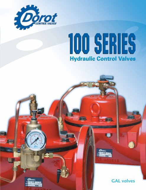
H y d r a u l i cDorot Series 100The direct sealing diaphragm valves were introduced to theworld market for the first time by DOROT CONTROL VALVESat 1982. This valve is operated by the pressure of the pipelineand is used for various control applications in water supply,fire fighting, industrial, sewage and irrigation systems.The only moving component is a reinforced diaphragm, which:a. Drip tight seals the liquid passage in the closed valveb. Allows free passage in the fully open valve with minimalobstruction to the flow linec. Throttles the flow passage in the modulating valve, asdictated by the pressure in the control chamberThe valve can be closed or modulated using the line pressureor an external separate pressure source that is equal or higherthan the line pressure.Dorot S-100 valves are made for easy, inline maintenance,executed also by unskilled personal using basic tools.There are no shafts, bearings or seals that may corrode andthere is no wear and tear by dirty abrasive water or chemicals.Features and Benefits• Structural simplicity• Superb design featuring exceptionally low pressure lossesat high flow rates• Can be used for regulating from no-flow to maximalflow with no need for additional throttling devices orby-pass valves• For natural liquids, sea water and industrial effluents• A wide selection of materials, coating anddiaphragm types• All valve models fit a wide variety of control applicationsusing Dorot pilot valves4
Series 100Technical DataDiaphragm Selection Table*Diameter Type No. Pressure Rangemm inch mwc psi20, 25 3 /4 ” Standard 18 12-160 17-230,1”Low Pressure 85 5-100 7-14040 1 1 Standard 13 12-160 17-230/2”S. Low Pressure 82 5-50 7-70Standard 03 15-160 21-23050, 65 2”, 2 1 Low Pressure 02 7-100 10-140/2”, 323”S. Low Pressure 12 4-50 6-70Extreme 60 20-160 28-23050 HP 2” HP High Pressure 69 10-250 15-360Standard 32 12-160 17-23080, 100 3”, 4” Low Pressure 05 4-100 6-140Extreme 61 20-160 28-23080 HP 3” HP High Pressure 70 10-250 15-360100 HP 4” HP High Pressure 71 10-250 15-360Standard 62 15-160 21-230150 6”, 868Low Pressure 09 5-100 7-140S. Low Pressure 91 2-60 3-85Extreme 35 20-160 28-230150 HP 6” HP High Pressure 72 10-250 15-360Standard 36 7-160 10-230200, 300, 350 8”, 12”, 14” Low Pressure 37 2-100 3-140Extreme 63 20-160 28-230200 HP 8” HP High Pressure 73 10-250 15-360250 10”Standard 40 7-160 10-230Low Pressure 50 2-100 3-140250 HP , 400 HP , 10” HP , 16” HP , High Pressure 78 10-250 15-360500 HP , 600 HP 20” HP , 24” HP Low Pressure 92 2-100 3-140* Standard Diaphragm: Nylon Reinforced Natural Rubber. Optional Materials: Nitrile, EPDM, Neoprene Available Upon Request.** HP = High PressurePressure RatingPressure rating of series 100 valves is body strength, connection standard and diaphragm type.Pressure rating of valve body of standard models: 16 Bar / 230 psi.Pressure rating of valve body of high pressure models: 25 Bar / 360 psi.Connection standard is marked on the identification plate, assembled on the valve body.Diaphragms operation pressure range is presented at the above table.DorotCONTROL VALVES E V E R Y T H I N G I S U N D E R C O N T R O L7
Series 100Dimensions and WeightsLTechnical DatawDHStraight Flow, Threaded ConnectionValve SizeLHDWWeightCast Iron Bronze Cast Iron Bronze Cast Iron Bronzemm inch mm inch mm inch mm inch mm inch mm inch mm inch Kg Lbs Kg Lbs20 3/4 115 4.53 112 4.41 43 1.69 43 1.69 20 0.79 68 2.68 1 2.2 1 2.225 1 120 4.72 119 4.69 52 2.05 52 2.05 24 0.94 68 2.68 1 2.2 1 2.240 1 1/2 170 6.69 149 5.87 93 3.66 86 3.39 33 1.3 93 3.66 2.2 4.9 1.8 450 2 188 7.4 184 7.24 115 4.53 101 3.98 42 1.65 112 4.41 3.2 7 2.6 5.765 2 1/2 219 8.62 212 8.35 118 4.65 109 4.29 46 1.81 112 4.41 3.6 7.9 3.4 7.580 LF 323 225 8.86 221 8.7 126 4.96 116 4.57 54 2.13 112 4.41 4.5 9.9 3.9 8.580 3 316 12.44 316 12.44 135 5.31 135 5.31 53 2.09 200 7.87 11 24* LF = Low FlowStraight Flow, Grooved Connection (Vic.)Valve Size L H D W Weightmm inch mm inch mm inch mm inch mm inch Kg Lbs40 1 1/2 177 6.97 81 3.19 26 1.02 93 3.66 1.8 450 2 190 7.48 100 3.94 33 1.3 112 4.41 2.6 5.780 LF 323 201 7.91 120 4.72 47 1.85 112 4.41 3 6.680 3 286 11.26 124 4.88 47 1.85 200 7.87 11 24.3100 4 317 12.48 133 5.24 60 2.36 194 7.64 12 26.4150 6 392 15.43 250 9.84 82 3.23 300 11.81 31 68.3LDHwAngle Flow, Grooved Connection (Vic.)Valve Size H D W Weightmm inch mm inch mm inch mm inch Kg Lbs80 3 240 9.45 170 6.69 200 7.87 10.5 23.1100 4 250 9.84 185 7.28 200 7.87 11.5 25.4Angle Flow, Threaded ConnectionValve Size H D W Weightmm inch mm inch mm inch mm inch Kg Lbs40 1 1/2 110 4.33 75 2.95 93 3.66 1.7 3.750 2 136 5.35 90 3.54 112 4.41 2.4 5.380 LF 323 165 6.5 114 4.49 112 4.41 3.6 7.980 3 239 9.41 145 5.71 200 7.87 10.8 23.8wDHAngle Flow, Flanged ConnectionValve Size H D W Weightmm inch mm inch mm inch mm inch Kg Lbs80 3 278 10.9 174 6.85 200 7.87 18 39.7100 4 300 11.8 185 7.28 230 9.06 21 46.3150 6 380 15 230 9.06 300 11.8 45 99.2wDH8DorotCONTROL VALVES E V E R Y T H I N G I S U N D E R C O N T R O L
Series 100Technical DataDimensions and WeightsStraight Flow, Flanged Connection - Standard Models 16 Bar/230 psiValve Size L H D WWeightCast Iron Duct. Iron Bronzemm inch mm inch mm inch mm inch mm inch Kg Lbs Kg Lbs Kg Lbs50 2 200 7.87 166 6.54 85 3.35 166 6.54 7.2 15.8 7.7 17 8 17.680 LF 323 200 7.87 202 7.95 105 4.13 200 7.87 11 24.3 11.8 2680 3 285 11.22 200 7.87 105 4.13 200 7.87 17 37.5 18.2 40.1 19 42100 4 305 12.01 230 9.06 110 4.33 230 9.06 22 48.5 24 53 24 53150 6 390 15.35 314 12.36 145 5.71 300 11.8 46 101 49 108 51 112200 LF 868 385 15.16 350 13.78 170 6.69 365 14.4 50 110 54 119200 8 460 18.11 400 15.75 170 6.69 365 14.4 80 176 86 190 89 196250 10 535 21.06 445 17.52 205 8.07 440 17.3 117 258 125 276 131 289300 12 580 22.83 495 19.49 240 9.45 490 19.3 156 344 167 368 147 324350 14 580 22.83 495 19.49 270 10.6 540 21.3 182 401 172 379 180 397LwLwDDHHStraight Flow, Flanged Connection - High Pressure Models 25 Bar/360 psiValve Size L H D W Weightmm inch mm inch mm inch mm inch mm inch Kg Lbs50 2 228 8.98 169 6.65 85 3.35 175 6.9 10 2250 TH 2 TH 250 8.98 120 6.65 42 1.65 175 6.9 6 1380 3 310 12.2 237 9.33 105 4.13 200 7.87 30 66.1100 4 356 14.02 263 10.35 120 4.72 260 10.24 38 83.8150 6 436 17.17 378 14.88 150 5.91 320 12.6 75 165.3200 8 530 20.87 481 18.94 180 7.09 400 15.75 123 271250 10 636 25.04 546 21.5 215 8.46 495 19.49 190 419400 16 715 28.15 830 32.68 310 12.2 830 32.68 433 955450 18 715 28.15 830 32.68 340 13.39 830 32.68 460 1014500 20 900 35.43 970 38.19 490 19.29 980 38.58 674 1486600 24 900 35.43 970 38.19 490 19.29 980 38.58 696 1534* TH = ThreadedLwLwDDHHDorotCONTROL VALVES E V E R Y T H I N G I S U N D E R C O N T R O L9
Series 100Technical Data<strong>Hydraulic</strong> PerformanceValve Sizemm 20 25 40 50 65 80 LF 80 100 150 200 LF 200 250 300 350 400 450 500 600inch 3/4 1 1 1/2 2 2 1/2 323 3 4 6 868 8 10 12 14 16 18 20 24Max. Flow m 3 /hr 6 10 25 40 40 40 90 100 350 350 480 970 1400 1400 2500 2500 3890 5500Continuance gpm 26.4 44 110 176 176 176 396 440 1540 1540 2112 4268 6160 6160 11000 11000 17116 24200Max. Flow m3 /hr 16 27 68 109 109 109 245 273 955 955 1309 2645 3818 3818 6818 6818 10609 10609Intermittent gpm 72 120 300 480 480 480 1080 1200 4200 4200 5760 11640 16800 16800 30000 30000 46680 46680Minimal Flowm 3 /hr < 1gpm < 5Kv m 3 /hr @ 1 bar 15 22 64 95 95 95 170 220 600 670 800 1250 1900 1900 2600 2600 5370 5370Cv gpm @ 1 psi 17 26 75 110 110 110 200 260 700 780 930 1460 2220 2220 3030 3030 6275 6275Kv * m 3 /hr @ 1 bar - - - 78 - - 120 200 550 - 800 1300 - - 2600 2600 5370 5370Cv * gpm @ 1 psi - - - 91 - - 140 230 640 - 930 1520 - - 3030 3030 6275 6275* High pressure modelsmQ[ ] 2P(Bar) = ( 2hrQ[gpm]Kv) P(Psi) = (Cv)Headloss Chart10987654psimwc1098765433/4” 1”1 1/2”2”, 2 1/2”, 3233”4”6”, 8688”10”12”, 14”16”, 18”20”, 24”3221 10 100 1000 500010100100010000m /hr3gpmCavitation DataUpstream Pressurepsi bar253503002025015200150 10100550Cavitation zoneSafe zone for Bronze valvesSafe operation zone00 1 2 3 4 5 6 7 810 20 30 40 50 60 70 80 90 100 110Downstream Pressurebarpsi10DorotCONTROL VALVES E V E R Y T H I N G I S U N D E R C O N T R O L
Series 100Technical DataMain Components:Pilot valves forsuperb regulationat high reliabilityUnique SesignCreating low lossesat high flow ratesIntemal SST spring:allows the use ofwide rangeof diaphragmrubber typesFlexible reinforoeddiaphragm-nobearing, guides orintemal seals usedPolymeric coating,UV and corrosionresistantWide materialsvarietyComponentsComponent No. Description1 Body2 Bonnet3 Diaphragm4 Spring5 Spring Disc6 Bolt7 Short Bolt8 Washer9 Nut10 Suspension Ring (Hook)10 8 79624 51398654219865421333DorotCONTROL VALVES E V E R Y T H I N G I S U N D E R C O N T R O L11
Series 100MManually <strong>Control</strong>led Valve45DescriptionThe valve is controlled manually by a three port selectorthat allows the user to select the closed, opened orremote-controlled position of the valve. The control iseffected effortlessly and quickly, even under high pressureconditions321Features• Effortless open/close activation• Fast response• Clog-free operation• Can be added as manual over-ride to any othercontrol functionOptional <strong>Control</strong> System Components:1 Main Valve2 Self-flushing filter3 Cock valve** Optional component4 3-way selector valve5 Accelerator relay (optional for valveslarger than 150mm/6")Purchase SpecificationsThe valve will be a direct sealing diaphragm type, whichallows inline maintenance. No stem, shaft or guidebearing will be located within the water passage.The valve will be activated by the line pressure or by anexternal hydraulic or pneumatic pressure.The valve position will be controlled by a hand operatedselector valve. The valve and the controls will be a DorotSeries 100 valve or similar in all aspects.Quick Sizing• Valve size same as line or one size smaller• Maximum flow speed for continuous operation5.5 m/sec (18 ft/sec)Design Considerations• The valve should be suited for the maximal flow andallowed headloss• Preferred selection of low pressure diaphragmswhen the valve is expected to stay in open positionfor long periodsTypical ApplicationDorot Manually controlled valve installed in an underground, flooded pit.Manual activation is enabled from top by the selector valve.12DorotCONTROL VALVES E V E R Y T H I N G I S U N D E R C O N T R O L
Series 100ELSolenoid <strong>Control</strong>led Valve45DescriptionA 3-way solenoid valve, activated by an electric currentor an electric pulse, opens or closes the main valve.The standard valve is supplied in the "normally closed"position. The "normally open" position is optional.Electric activation can be added to other controlapplications on request.321Features• Low power electric activation• Fast response• Simple and reliable design• Can be added as electric over-ride to any othercontrol functionPurchase SpecificationsThe valve will be hydraulic, direct sealing diaphragm type,which allows inline maintenance. No stem, shaft or guidebearing will be located within the water passage. The valvewill be activated by the line pressure or by an externalhydraulic or pneumatic pressure. The valve position willbe controlled by an electric solenoid valve. The valve andthe controls will be a Dorot Series 100 valve or similar inall aspects.Optional <strong>Control</strong> System Components:1 Main Valve2 Self-flushing filter3 Cock valve** Optional component4 3/2 Solenoid valve5 Accelerator relay (optional for valveslarger than 150mm/6")Quick Sizing• Valve size same as line or one size smaller• Maximum flow speed for continuous operation5.5 m/sec (18 ft/sec)Design Considerations• The valve should be suited for the maximal flow andallowed headloss• Prefer selection low pressure diaphragms when the valveis expected to stay in open position for long periods• The valve can be opened by the electric command (NC)or closed by it (NO). The definition refers to the mainvalve operation and not the solenoid's characteristicsTypical ApplicationDorot Solenoid <strong>Control</strong>led valve, controlled by a local controller.DorotCONTROL VALVES E V E R Y T H I N G I S U N D E R C O N T R O L13
Series 100RC<strong>Hydraulic</strong> Remote <strong>Control</strong>led ValveRemote pressurecommand453DescriptionA 3-way relay valve, activated by hydraulic or pneumaticpressure command, opens or closes the main valve. Thestandard valve is supplied in the "normally closed" position.The "normally open" position is optional. <strong>Hydraulic</strong> activationcan be added to other control applications on request.Features• Fast response even for long control lines• Simple and reliable design• Can be added as pressure command over-ride to anyother control function2Optional <strong>Control</strong> System Components:1 Main Valve2 Self-flushing filter3 Cock valve** Optional component14 Manual over-ride selector valve*5 Accelerator relay (other types areoptional)Purchase SpecificationsThe valve will be hydraulic, direct sealing diaphragm type,which allows inline maintenance. No stem, shaft or guidebearing will be located within the water passage. The valvewill be activated by the line pressure or by an externalhydraulic or pneumatic pressure. The valve position willbe controlled by a hydraulic relay. The valve and the controlswill be a Dorot Series 100 valve or similar in all aspects.Quick Sizing• Valve size same as line or one size smaller• Maximum flow speed for continuous operation 5.5m/sec (18 ft/sec)Design Considerations• The valve should be suited for the maximal flow andallowed headloss• Prefer selection low pressure diaphragms when the valveis expected to stay in open position for long periods• The valve can be opened by the pressure command (NC)or closed by it (NO). The definition refers to the mainvalve operation and not the relay's characteristicsTypical ApplicationDorot <strong>Hydraulic</strong> Remote <strong>Control</strong>led Valve, activated by a remotepressure command.14DorotCONTROL VALVES E V E R Y T H I N G I S U N D E R C O N T R O L
Series 100PRPressure Reducing Valve54DescriptionThe valve maintains a preset downstream pressure,regardless of upstream pressure or flow rate fluctuation.The main valve is controlled by either a 3-way pilot valve(allowing full opening when upstream pressure drops belowthe pressure set-point), or by a 2-way pilot valve (creatinga minimal differential in open position).321Features• Accurate, stable control from no-flow to full flow• Simple and reliable design• Exceptionally low losses at high flow• WRAS Approval no. 04251Purchase SpecificationsThe valve will be hydraulic, direct sealing diaphragm type,which allows inline maintenance. No stem, shaft or guidebearing will be located within the water passage.The valve will be activated by the line pressure or by anexternal hydraulic or pneumatic pressure. The valve willbe operated by a pressure reducing pilot valve to achieveconstant outlet pressure, regardless of upstream pressureor flow variations. The valve and the controls will be aDorot Series 100 valve or similar in all aspects.Optional <strong>Control</strong> System Components:1 Main Valve4 Manual over-ride selector valve*2 Self-flushing filter 5 3-way pilot valve (other types are optional)3 Cock valve** Optional componentQuick Sizing• Valve size same as line or one size smaller• Maximum flow speed for continuous operation5.5 m/sec (18 ft/sec)Design Considerations• The valve should be suited for the maximal flow andallowed headloss• In case upstream pressure may drop to the required setpressure, select 3-way control pilot• Large pressure differentials may cause cavitation damage.Consult Dorot for solutions if such conditions are expectedTypical ApplicationDorot Pressure Reducing Valve reduces varying supply pressure to astabilized downstream pressure.DorotCONTROL VALVES E V E R Y T H I N G I S U N D E R C O N T R O L15
Series 100PSPressure Sustaining & Relief Valve543DescriptionThe valve maintains upstream pressure, regardlessof flow rate variations. The valve will be in the"closed" position if the upstream pressure dropsbelow the set-point and will fully open when theupstream pressure exceeds the set-point.2Optional <strong>Control</strong> System Components:Features• Accurate, stable control from no-flow to full flow• Simple and reliable design• Exceptionally low losses at high flowPurchase SpecificationsThe valve will be hydraulic, direct sealing diaphragmtype, which allows inline maintenance. No stem,shaft or guide bearing will be located within thewater passage. The valve will be activated by theline pressure or by an external hydraulic or pneumaticpressure. The valve will be operated by a pressuresustaining pilot valve to maintain constant inletpressure, regardless of flow variations. The valveand the controls will be a Dorot Series 100 valveor similar in all aspects.1 Main Valve2 Self-flushing filter3 Cock valve** Optional component4 Manual over-ride selector valve*5 3-way pilot valve (other types are optional)Quick Sizing• Valve size same as line or one size smaller• Maximum flow speed for continuous operation5.5 m/sec (18 ft/sec)Design Considerations• The valve should be suited for the maximal flowand allowed headloss• Check for possible cavitation conditions andconsult Dorot in case such conditions are expectedTypical ApplicationDorot Pressure Relief Valve relieving pump surplus flow from the system,thus preventing high pressure at low demand conditions.16DorotCONTROL VALVES E V E R Y T H I N G I S U N D E R C O N T R O L
Series 100DIPressure Differential Sustaining Valve543DescriptionThe valve maintains a preset pressure differential betweenits upstream and downstream sides. The valve can controlbooster pump discharge, heating and cooling systems,bypass configurations, filters and other similar systems.21Features• Accurate, stable control from no-flow to full flow• Simple and reliable design• Exceptionally low losses at high flowPurchase SpecificationsThe valve will be hydraulic, direct sealing diaphragm type,which allows inline maintenance. No stem, shaft or guidebearing will be located within the water passage. The valvewill be activated by the line pressure or by an externalhydraulic or pneumatic pressure. The valve will be operatedby a pressure sustaining differential pilot valve so to maintaina minimal pressure differential, regardless of flow variations.The valve and the controls will be a Dorot Series 100 valveor similar in all aspects.Optional <strong>Control</strong> System Components:1 Main Valve4 Manual over-ride selector valve*2 Self-flushing filter 5 3-way pilot valve (other types are optional)3 Cock valve** Optional componentQuick Sizing• Valve size same as line or one size smaller• Maximum flow speed for continuous operation5.5 m/sec (18 ft/sec)Design Considerations• The valve should be suited for the maximal flow andallowed headloss• Check for possible cavitation conditions and consultDorot in case such conditions are expected• The connection points of the sensing tubes must beselected in locations free of turbulence and localinterferencesTypical ApplicationDorot Pressure Differential Sustaining Valve controls the flowat the discharge of a booster pump whose suction pressure varies.DorotCONTROL VALVES E V E R Y T H I N G I S U N D E R C O N T R O L17
Series 100FRFlow <strong>Control</strong> Valve53426DescriptionThe valve limits the flow rate in the network to a preset ,value regardless of upstream pressure variations.The valve fully opens when the flow rate drops belowthe set point.Optional <strong>Control</strong> System Components:1Features• Accurate, stable control• Simple and reliable design• Low losses when the demand is lower than the set flowPurchase SpecificationsThe valve will be hydraulic, direct sealing diaphragm type,which allows inline maintenance. No stem, shaft or guidebearing will be located within the water passage.The valve will be activated by the line pressure or by anexternal hydraulic or pneumatic pressure. The valve willbe operated by a pressure reducing differential pilot valvefor controlling the flow through the main valve, regardlessof pressure variations. The valve and the controls will bea Dorot Series 100 valve or similar in all aspects.1 Main Valve2 Self-flushing filter3 Cock valve*4 Manual over-ride selector valve** Optional component5 3-way differential pilot valve(other types are optional)6 Orifice plateQuick Sizing• Valve size same as line or one size smaller• Maximum flow speed for continuous operation5.5 m/sec (18 ft/sec)Design Considerations• A 1/2 " pressure sensing port should be provided,upstream of the valve• Check for possible cavitation conditions and consultDorot in case such conditions are expected• An additional pressure loss of about 2.5 mwc is createdby the orifice plate (at the set flow)Typical ApplicationDorot Flow <strong>Control</strong> Valve limits the flow to a specific customer.18DorotCONTROL VALVES E V E R Y T H I N G I S U N D E R C O N T R O L
Series 100FEExcessive Flow Shut-off Valve534326DescriptionThe valve closes drip tight when the flow rate exceedsthe normal value (due to pipe rupture).The valve will manually re-set open after fixing the break.1Features• <strong>Hydraulic</strong> burst protection.No electronic controllers are used• Simple and reliable design• Low lossesPurchase SpecificationsThe valve will be hydraulic, direct sealing diaphragmtype, which allows inline maintenance. No stem, shaftor guide bearing will be located within the water passage.The valve will be activated by the line pressure or by anexternal hydraulic or pneumatic pressure. The valve willbe operated by a pressure reducing differential pilot valvefor closing when the flow through the main valve exceedsthe safe level, regardless of pressure variations. The valveand the controls will be a Dorot Series 100 valve or similarin all aspects.Optional <strong>Control</strong> System Components:1 Main Valve2 Self-flushing filter3 Cock valve*4 Manual over-ride selector valve** Optional component5 3-way differential pilot valve(other types are optional)6 Orifice plateQuick Sizing• Valve size same as line or one size smaller• Maximum flow speed for continuous operation5.5 m/sec (18 ft/sec)Design Considerations• A 1/2" pressure sensing port should be provided,upstream of the valve• The valve is adjusted to close when the flow rateexceeds the maximal design flow by 10%-20%• An additional pressure loss of about 2 mwc is createdby the orifice plate (at the normal flow)Typical ApplicationDorot excessive flow shutoff valve installed to preventflood damages caused by pipe rupture.DorotCONTROL VALVES E V E R Y T H I N G I S U N D E R C O N T R O L19
Series 100FLModulating Float <strong>Control</strong>led Valve4533DescriptionThe main valve is controlled by a float valve, located in thetank or reservoir and set at the required maximum waterlevel. The valve maintains the maximum level continuously.Features• Accurate and repeatable level control• Simple and reliable design• Easy installation and maintenance• Adjusts the inlet flow to the reservoir's outlet flow• WRAS Approval no. 0009092Purchase SpecificationsThe valve will be hydraulic, direct sealing diaphragm type,which allows inline maintenance. No stem, shaft or guidebearing will be located within the water passage.The valve will be activated by the line pressure and beoperated by a modulating, 2-way float activated pilotvalve. The valve and the controls will be a Dorot Series100 valve or similar in all aspects.21Optional <strong>Control</strong> System Components:1 Main Valve4 Needle valve2 Self-flushing filter5 Modulating float pilot valve3 Cock valve** Optional componentQuick Sizing• Valve size same as the fill line or one size smaller• Maximum flow speed for continuous operation5.5 m/sec (18 ft/sec)Design Considerations• The valve should be suited for the maximal flow• Upstream pressure at closed position should be at least10m (15psi) higher than the hydrostatic water pressureat the downstream• Large pressure differentials may cause cavitation damage.Consult Dorot for solutions if such cases are expected• Prefer use of differential level control in case excessivenoise should be avoided (residential areas)Typical ApplicationDorot Modulating Float <strong>Control</strong>led valve prevents tank overflow.20DorotCONTROL VALVES E V E R Y T H I N G I S U N D E R C O N T R O L
Series 100FLELElectric Float <strong>Control</strong>led Valve<strong>Control</strong> Panel4 65DescriptionAn electric sensor float, located in the tank/reservoir, sendsa command to a solenoid controlled valve. The main valvewill fully open when the solenoid activated and will closedrip tight when the solenoid de-energized, thus enablingaccurate and reliable differential level control.Optional Addition: Stepped Surge-Preventing Closure.Features• Accurate and repeatable differential level control• Low power electric activation• Fast response• Simple and reliable design• Easy installation and maintenancePurchase SpecificationsThe valve will be hydraulic, direct sealing diaphragm type,which allows inline maintenance. No stem, shaft or guidebearing will be located within the water passage.The valve will be activated by the line pressure or by anexternal hydraulic or pneumatic pressure. The valve positionwill be controlled by an electric solenoid valve activatedfrom a float in the tank/reservoir. The valve and the controlswill be a Dorot Series 100 valve or similar in all aspects.32Optional <strong>Control</strong> System Components:1 Main Valve2 Self-flushing filter3 Cock valve*4 3/2 Solenoid valve* Optional component15 Accelerator relay (optional for valveslarger than 150mm/6")6 Electric float switchQuick Sizing• Valve size same as line or one size smaller• Maximum flow speed for continuous operation5.5 m/sec (18 ft/sec)Design Considerations• The valve should be suited for the maximal flow andallowed headloss• The valve can be opened by the electric command (NC)or closed by it (NO). The definition refers to the mainvalve operation and not to the solenoid's characteristicsTypical ApplicationDorot Electric Float <strong>Control</strong>led Valve controlling the water volume in a tank.DorotCONTROL VALVES E V E R Y T H I N G I S U N D E R C O N T R O L21
Series 100FLDIDifferential Float <strong>Control</strong>led Valve5463DescriptionA float valve controls the main valve, closing it when thewater reaches maximum level, and opening it when thewater drops to its preset minimum level. The differentialbetween the maximum and the minimum levels is adjustable.Optional Addition: Stepped Surge-Preventing Closure.2Optional <strong>Control</strong> System Components:1Features• Accurate and repeatable differential level control• Adjustable differential• Fast response• Simple and reliable design• Easy installation and maintenance1 Main Valve2 Self-flushing filter3 Cock valve*4 Manual over-ride selector valve** Optional component5 Accelerator relay (optional forvalves larger than 150mm/6")6 4-way differential pilot valve(other types are optional)Purchase SpecificationsThe valve will be hydraulic, direct sealing diaphragm type,which allows inline maintenance. No stem, shaft or guidebearing will be located within the water passage.The valve will be activated by the line pressure or by anexternal hydraulic pressure. The valve position will becontrolled by a 4-way float pilot located at the top of thetank/reservoir. The valve and the controls will be a DorotSeries 100 valve or similar in all aspects.Quick Sizing• Valve size same as line or one size smaller• Maximum flow speed for continuous operation5.5 m/sec (18 ft/sec)Design Considerations• The valve should be suited for the maximal flow.• Upstream pressure at closed position should be at least10m (15psi) higher than the static water pressure at thedownstream• Fast stream and waves may cause mechanical damageto the float levers. It is advisable to install the pilot in astill part of the reservoirTypical ApplicationDorot Differential Float Pilot <strong>Control</strong>led Valve controlling the watervolume in a filling or emptying tank.22DorotCONTROL VALVES E V E R Y T H I N G I S U N D E R C O N T R O L
Series 100ALAltitude Pilot <strong>Control</strong>led ValveTank/Reserviorconnection54DescriptionThe main valve is controlled by a highly sensitive pilot,located outside the tank. The pilot opens or closes thevalve in response to the static pressure of the water.The pilot allows for differential adjustments between themaximum and minimum level. Optional Addition:Stepped Surge-Preventing Closure.321Features• Accurate and repeatable differential level control• Fast response• Easy access - no float is located in the tank/reservoir• Simple and reliable design• Easy installation and maintenanceOptional <strong>Control</strong> System Components:1 Main Valve2 Self-flushing filter3 Cock valve** Optional component4 Manual over-ride selectorvalve*5 High sensitivity altitudecontrol pilot valvePurchase SpecificationsThe valve will be hydraulic, direct sealing diaphragm type,which allows inline maintenance. No stem, shaft or guidebearing will be located within the water passage.The valve will be activated by the line pressure or by anexternal hydraulic or pneumatic pressure. The valve positionwill be controlled by a hydrostatic pressure sensing pilotvalve. The valve and the controls will be a Dorot Series100 valve or similar in all aspects.Quick Sizing• Valve size same as line or one size smaller• Maximum flow speed for continuous operation5.5 m/sec (18 ft/sec)Design Considerations• The valve should be suited for the maximal flow• The pilot valve must be located at least 2 meters belowthe closing level in the tank• When water-hammer/surge expected duringclosure - add stepped surge preventing closure functionto the altitude control pilotTypical ApplicationDorot Altitude Pilot <strong>Control</strong>led Valve controlling the water volume in anelevated tank.DorotCONTROL VALVES E V E R Y T H I N G I S U N D E R C O N T R O L23
Series 100BCBooster Pump <strong>Control</strong> Valve674568733DescriptionThe valve eliminates damaging surges caused by pumpstart-up and shut-off. The electrically activated valvegradually opens on pump start up, and slowly closes beforethe pump is switched off. The valve will automatically closedrip tight in case of power failure. Optional Additions: FlowRate Limitation, Extended Closure, Two Stage Operating,Pressure Reducing and Pressure Sustaining.Features• No slam operation• Exceptionally low losses at high flow conditions• Simple and reliable design• Easy installation and maintenance2Optional <strong>Control</strong> System Components:1 Main Valve2 Self-flushing filter3 Cock valve*4 3/2 Solenoid valve* Optional component15 Accelerator relay (optional for valves largerthan 150mm/6")6 Open/close speed adjustment needle valve7 Check valve8 Limit switch assembly2Purchase SpecificationsThe valve will be hydraulic, direct sealing diaphragm type,which allows inline maintenance. No stem, shaft or guidebearing will be located within the water passage. The valvewill be activated by the line pressure or by an externalhydraulic or pneumatic pressure. The valve position willbe controlled by an electric solenoid valve with adjustableopen/close speed control valves. The valve and the controlswill be a Dorot Series 100 valve or similar in all aspects.Quick Sizing• Valve size same as line or one size smaller• Maximum flow speed for continuous operation5.5 m/sec (18 ft/sec)Design Considerations• The valve should be suited for the maximal flow• Closure time is related to the pipe length and should beextended for longer pipe• For power failure situations, add a fast reacting checkvalvein series and a surge anticipating valve to reliefpossible surgesTypical ApplicationDorot Booster Pump <strong>Control</strong> Valve preventing surges caused by pumpstartup and shutoff and drainage of main pipe.24DorotCONTROL VALVES E V E R Y T H I N G I S U N D E R C O N T R O L
Series 100DWDeep Well (Borehole) Pump <strong>Control</strong> Valve6457683DescriptionThe valve eliminates surges caused by the start-up andshut-off of vertical or submersible pumps. It is a relief valve,assembled on a T-junction of the main pipeline. When thepump starts, the valve slowly closes, gradually increasingnetwork pressure. Before pump shut-off, the valve slowlyopens, gradually reducing network pressure.2Optional <strong>Control</strong> System Components:1Features• No slam operation• Simple and reliable design• Easy installation and maintenance• Low Resistance and high flow capacityPurchase SpecificationsThe valve will be hydraulic, direct sealing diaphragm type,which allows inline maintenance. No stem, shaft or guidebearing will be located within the water passage. The valvewill be activated by the line pressure or by an externalhydraulic or pneumatic pressure. The valve position willbe controlled by an electric solenoid valve with adjustableopen/close speed control valves. The valve and the controlswill be a Dorot Series 100 valve or similar in all aspects.Quick Sizing• The valve should be sized to match the well flow at5 mwc/8 psi in the valve site (pump head - water tabledepth): D[mm] ≥ 170 x √Flow [m3/hr]D[inch] ≥ 0.55 x √Flow [gpm]1 Main Valve2 Self-flushing filter3 Cock valve*4 3/2 Solenoid valve* Optional component5 Accelerator relay (optional for valveslarger than 150mm/6")6 Open/close speed adjustment needle valve7 Check valve8 Limit switch assemblyDesign Considerations• The valve should be suited for the maximal flow• Closure time is related to the pipe length and should beextended for longer pipe• For power failure situations, add a fast reacting checkvalvein series and a surge anticipating valve to reliefpossible surgesTypical ApplicationDorot Deep Well Pump <strong>Control</strong> Valve preventing surges caused by pumpstart-up or shut-off.DorotCONTROL VALVES E V E R Y T H I N G I S U N D E R C O N T R O L25
Series 100RESurge Anticipating Valve376633453DescriptionThe valve protects the pumping system from water hammer,caused by sudden pump shut-off (case of power failure,for example). The valve is assembled on a T-junction of themain pipeline, instantly opens when the pump stops, relievingthe returning high pressure wave. The valve slowly closesonce the pressure returns to the static level. The valve alsofunctions as a pressure relief valve.2Optional <strong>Control</strong> System Components:1Features• No slam operation• Simple and reliable design• Easy installation and maintenance• Low Resistance and high flow capacity• Protection for sewage as well as clean water pumpingsystemsPurchase SpecificationsThe valve will be hydraulic, direct sealing diaphragm type,which allows inline maintenance. No stem, shaft or guidebearing will be located within the water passage. The valvewill be activated by the line pressure or by an externalhydraulic or pneumatic pressure. The valve will be operatedby pressure relief pilot valve for opening at a low pressureset point and another pilot for pressure relief at a highpressure set-point. The valve and the controls will be aDorot Series 100 valve or similar in all aspects.Quick Sizing• The valve should be sized to match the 80% of the normalflow at static head in the valve site:D[mm] ≤ √(250 x Flow[m3/hr] / √Pressure[mwc])D[inch] ≤ √(0.109 x Flow[gpm] / √Pressure[psi])1 Main Valve2 Self-flushing filter3 Cock valve*4 Low-pressure relief pilot valve* Optional component5 High-pressure relief pilot valve6 Needle valve7 Pressure gaugeDesign Considerations• Install a manual separation/throttling valve, upstreamof the valve position• Closure time is related to the pipe length and should beextended for longer pipe• The valve sensor tube must be connected to themain lineTypical ApplicationDorot Surge Anticipating Valve prevents water-hammer/surgescaused by an un-expected pump shut-off.26DorotCONTROL VALVES E V E R Y T H I N G I S U N D E R C O N T R O L
Series 100QRQuick Pressure-relief Valve453DescriptionThe valve opens instantly when the pressure in the pipelineexceeds the safe level, thus relieving excessive pressurefrom the network. When the pressure returns to normal,the valve closes slowly, at an adjustable pace.21Features• No slam operation• Simple and reliable design• Easy installation and maintenance• Low Resistance and high flow capacity• Protection for sewage as well as clean water pumpingsystemsPurchase SpecificationsThe valve will be hydraulic, direct sealing diaphragm type,which allows inline maintenance. No stem, shaft or guidebearing will be located within the water passage. The valvewill be activated by the line pressure or by an externalhydraulic or pneumatic pressure. The valve will be operatedby a pressure relief pilot valve for fast opening at a highpressure set-point. The valve and the controls will be aDorot Series 100 valve or similar in all aspects.Optional <strong>Control</strong> System Components:1 Main Valve4 Pressure relief pilot valve2 Self-flushing filter5 Needle valve3 Cock valve** Optional componentQuick Sizing• The valve should be sized to match the expected reliefflow at the set opening pressure:D[mm] ≤ √(250 x Flow[m3/hr] / √Pressure[mwc])D[inch] ≤ √(0.109 x Flow[gpm] / √Pressure[psi])Design Considerations• Install a manual separation valve, upstream of the valveposition• Closure time is related to the pipe length and should beextended for longer pipe• The valve opens instantly at the set pressure.For regulating the system pressure use a PressureSustaining Relief Valve and not a Quick Relief valveTypical ApplicationDorot Quick Pressure-relief Valve protects a system againstpressure surges caused by pump start-up or valves closure.DorotCONTROL VALVES E V E R Y T H I N G I S U N D E R C O N T R O L27
Series 100TOTwo Stage Opening Addition453DescriptionThe device can be added to any control function and willprevent damage caused by too fast filling of a drainedpipeline. The flow rate will be restricted, until the network,downstream of the valve is full and than a full opening ofthe valve is enabled. Please consult DOROT for more details.Features• Can be added to any pipe-filling control function• User adjusted filling pace• Completely hydraulic – no electronic controllers, batteriesor relays are used• Simple and reliable design21Optional <strong>Control</strong> System Components:1 Main Valve4 Pilot valve2 Self-flushing filter5 3-way selector valve*3 Cock valve** Optional componentPurchase SpecificationsThe valve will be hydraulic, direct sealing diaphragm type,which allows inline maintenance. No stem, shaft or guidebearing will be located within the water passage.The valve will be activated by the line pressure or by anexternal hydraulic or pneumatic pressure. The valve'sopening will be restricted by a two-stage opening controlthat limits the filling flow until the downstream system isfull. The valve and the controls will be a Dorot Series 100valve or similar in all aspects.Quick Sizing• Valve size same as line or one size smaller• Maximum flow speed for continuous operation5.5 m/sec (18 ft/sec)Design Considerations• The valve should be suited for the maximal flow andallowed headloss• Prefer selection low pressure diaphragms when the valveis expected to stay in open position for long periodsTypical ApplicationDorot two-stage function prevents water-hammer/surges caused by fastdrained pipe filling.28DorotCONTROL VALVES E V E R Y T H I N G I S U N D E R C O N T R O L
Series 100SPSurge Preventing Stepped-Closure Addition54DescriptionThe device can be added to any control function andautomatically adjusts the closing speed of a valve that islocated at the end of a long pipeline. This ensures a moderateflow change pace that prevents pressure surges fromevolving. Please consult DOROT for more details321Features• Can be added to any fast closing control function.• Automatically self-adjusted closing pace• Completely hydraulic – no electronic controllers,batteriesor relays are used• Simple and reliable designPurchase SpecificationsThe valve will be hydraulic, direct sealing diaphragm type,which allows inline maintenance. No stem, shaft or guidebearing will be located within the water passage.The valve will be activated by the line pressure or by anexternal hydraulic or pneumatic pressure. The valve'sclosure pace will be controlled by a stepped closure controlpilot that stops the closing procedure whenever surge/waterhammerconditions evolve. The valve and the controls willbe a Dorot Series 100 valve or similar in all aspects.Optional <strong>Control</strong> System Components:1 Main Valve4 Stepped closure adjusting pilot valve2 Self-flushing filter5 3-way selector valve*3 Cock valve** Optional componentQuick Sizing• Valve size same as line or one size smaller• Maximum flow speed for continuous operation5.5 m/sec (18 ft/sec)Design Considerations• The valve should be suited for the maximal flow andallowed headloss• Prefer selection low pressure diaphragms when thevalve is expected to stay in open position for long periods• Should be used whenever the supply pipe is longer than2 km/ 1.2 mile and the flow speed exceeds 1.5 m/secTypical ApplicationDorot stepped closure function prevents water-hammer/surges causedby fast closing level control valve.DorotCONTROL VALVES E V E R Y T H I N G I S U N D E R C O N T R O L29
Series 100ECPLC <strong>Control</strong>led Valve445DescriptionThe valve is controlled by a PLC controller that enables localor remote control of various functions such as, time relatedoperation, the batching of liquid, and conditional(automatically modified) control parameters, in variousapplications. A recommended option is using the Dorot"ConDor" controller that enables the selection from a vastrange of pre-programmed control functions and theircombinations.321Optional <strong>Control</strong> System Components:Features• Can perform any control function• Highly accurate and reliable electronic control• Low power actuation• Simple and reliable design• <strong>Control</strong>led by Dorot ConDor valve controller or by athird party controller1 Main Valve2 Self-flushing filter3 Cock valve** Optional component4 2/2, NC solenoid valve5 3-way selector valve*Purchase SpecificationsThe valve will be hydraulic, direct sealing diaphragm type,which allows inline maintenance. No stem, shaft or guidebearing will be located within the water passage. The valvewill be activated by the line pressure or by an externalhydraulic or pneumatic pressure. The valve position will bedetermined by a set of two solenoid valves controlled by aPLC controller. The valve and the controls will be a DorotSeries 100 valve or similar in all aspects.Quick Sizing• Valve size same as line or one size smaller• Maximum flow speed for continuous operation5.5 m/sec (18 ft/sec)Design Considerations• The valve should be suited for the maximal flow andallowed headloss• Solenoid wiring diameter should be selected so that theactivation voltage - losses will equal the rated value ±10%Typical ApplicationDorot PLC <strong>Control</strong>led Valve adjusts the flow rate following a set-pointsignal sent from a remote center.30DorotCONTROL VALVES E V E R Y T H I N G I S U N D E R C O N T R O L
Series 100DEDeluge Dry-pipe and Pre-action <strong>Valves</strong>53 4DescriptionThe valve prevents flow of water into fire extinguishingsprinklers system until it is activated by the activationdevices. Different valve and control system configurationsare available to meet the customer and relevantstandards demands. Please check Dorot Fire-Fightingpublications for further information.261Features• Fast opening• Simple and reliable design• Automatic reset• Wide range of applications• UL Approval no. VLFT EX.6543Optional <strong>Control</strong> System Components:1 Main valve4 Solenoid activation*2 Self-flushing filter5 Pilot activation (by detection line)*3 Manual activation valve 6 Drain valve* Optional componentPurchase SpecificationsThe valve will be hydraulic, direct sealing diaphragmtype, which allows inline maintenance. No stem, shaftor guide bearing will be located with in the water passage.The valve will be activated by the line pressure or byan external hydraulic or pneumatic pressure. The valveand the controls will be a Dorot Series 100 valve orsimilar in all aspects.Quick Sizing• Valve size same as line or one size smaller• Maximum flow speed for intermittent operation8 m/sec (26 ft/sec)Design Considerations• The valve should be suited for the maximal flowand allowed headloss• Check Dorot catalogue for Fire Fighting <strong>Valves</strong>for more information with regards to valve andapplications typesTypical ApplicationDorot valve, activated by a splinker detection line.DorotCONTROL VALVES E V E R Y T H I N G I S U N D E R C O N T R O L31
Series 100Pilots and AccessoriesPlastic Mini PilotsFor valve sizes 20mm to 100mm - 3 /4" to 4"Pressure rating: 10 bar / 145 psi29-100 - 3-way pressure reducing pilot valve29-200 - 3-way multi purpose (pressure reducing and sustaining) pilot valve29-300 - 3 way differential multi purpose(flow control, differential pressure sustaining)29-410 - 2-way pressure reducing pilot valve29-410 29-100 29-300 29-200Metal Mini PilotsFor valve sizes 20mm to 150mm - 3 /4" to 6"Pressure rating: 25 bar / 360 psi68-410 - 2-way pressure reducing pilot valve68-500 - 2-way pressure sustaining pilot valve29-110 - 3-way (pressure rating 16bar / 230psi) pressure reducing pilot valve68-500 68-410Metal PilotsFor valve sizes 40mm to 600mm - 1 1 /2" to 24"Pressure rating: 25 bar / 360 psiCXPR - 2-way pressure reducing pilot valve(CXRS - remote sensing, CXRD differential pressure reducing)CXPS - 2-way pressure sustaining pilot valve(CXSD differential pressure sustaining)31-310 - 3-way multi purpose (pressure reducing and sustaining) pilot valve76-200 - 3 way differential multi purpose(flow control, differential pressure sustaining)68-600 - 2-way pressure reducing pilot valve68-700 - 2-way pressure sustaining pilot valve68-600/68-700 31-310 CXPR CXPSHigh Sensitivity Metal PilotsFor valve sizes 40mm to 600mm - 1 1 /2" to 24"Pressure rating: 25 bar / 360 psi70-410 - 2-way differential pressure reducing mini pilot valve (flow control and altitude control)76-600 - 2-way differential pressure reducing pilot valve (flow control and altitude control)70-110 - 3 way differential multi purpose (flow control, altitude control and differential pressuresustaining) with adjustable differential70-410 70-11076-610Float PilotsFor valve sizes 40mm to 600mm - 1 1 /2" to 24"Pressure rating: 25 bar / 360 psi70-200 - Electric float70-300 - Modulating, 2-way plastic float pilot for irrigation use(pressure rating: 8 bar / 115 psi)70-400 - Modulating, 2-way metal float pilot70-610 - Horizontal, differential, 3-way metal float pilot70-550 - Vertical, differential, 3 and 4-way metal float pilot70-550 70-20070-40070-30070-61032DorotCONTROL VALVES E V E R Y T H I N G I S U N D E R C O N T R O L
Series 100Pilots and AccessoriesPlastic RelaysFor valve sizes 20mm to 150mm - 3 /4" to 6"Pressure rating: 10 bar / 145 psi25-300 3-way / 2 positions NO w. 3/8" ports hydraulic relay‘Galit’ 3-way / 2 positions NC or NO, small hydraulic relay‘GALIT’ 25-300Metal RelaysFor valve sizes 40mm to 600mm - 1 1 /2" to 24"Pressure rating: 25 bar / 360 psi66-210 3-way / 2 positions NO (66-213: NC) hydraulic relay66-300 3-way adjustable hydraulic relay28-200 2-way / 2 positions hydraulic relay66-210 66-310 28-200Mini SolenoidsFor irrigation valve sizes 20mm to 150mm - 3 /4" to 6"Pressure rating: 10 bar / 145 psiOperating Voltage:AC: 24VDC: 12V or 24VLatch 6-40VD2 2-way NC solenoid valveD3 3-way NC or NO solenoid valveD2D3Heavy-duty SolenoidsFor valve sizes 20mm to 600mm - 3 /4" to 24"Pressure rating: According to the selected orifice and solenoid typeOperating Voltage (others available upon request):AC: 24V, 110V or 220VDC: 12V or 24VLatch 9V, 12V, 24VB2 2-way NC or NO solenoid valveB3 3-way NC or NO solenoid valveB2B3<strong>Control</strong> FiltersSelf-Flushing, Inline - Stainless steel screen filter, located within themain valve, and rinsed continuously by the streamSizes: 1 /4", 1 /2"External, "Y" type - Stainless steel screen installed in a "Y"shaped body on the pressure source.Sizes: 3 /8", 1 /2"External, large - A large volume external filter“Y Filter” Self Flushing FilterDorotCONTROL VALVES E V E R Y T H I N G I S U N D E R C O N T R O L33
Contact ListCHINADorot Beijing OfficeRoom 1108 Henderson Centre Tower 2 No. 18Jianguomennei Dajie Dongcheng DistrictBeijing, CHINA, 100005Tel: 86 10 65814499Tel: 86 10 65188900Fax: 86 10 65188908Email: sales@dorot.com.cnwww.dorot.com.cnLATIN AMERICADorot Latin AmericaCoronel Diaz 2710 Piso 16,Capital Federal (1425),Buenos Aires, ARGENTINATel: 54 11 48015093Fax: 54 11 48054727Cell 1: 54 11 44046868Cell 2: 1 559 3609386Email: gmizrah@attglobal.netISRAELISRAELDorot <strong>Control</strong> <strong>Valves</strong>Kibbutz DorotD.N. Hof Ashkelon 79175, ISRAELTel: 972-8-6808848Fax: 972-8-6808751Email: info_d@dorot.comMEXICOMEXICOINDAGA SA DE CV (D.F., GDL, MTY, CUL.)Matriz: Rio Panuco 55, Despacho 701,Del. Cuauhtémoc, C.P. 06500, Mexico DFTel: 0155-1055-1777Fax: 0155-5592-1594Email: info@indaga.com.mxwww.indaga.com.mxUSAUSADorot <strong>Control</strong> <strong>Valves</strong> Inc.598 E. Shelldrake CircleFresno, CA 93720, USATel: 1-5594331648Fax: 1-5594331648Email: dorotus@attglobal.netSINGAPOREDorot <strong>Control</strong> <strong>Valves</strong> Singapore48-A Changi South Street 1SINGAPORE1486114Tel: 65 62199526Fax: 65 62199527Cell 1: 65 96952417 (Singapore)Cell 1: 62 811693851 (Indonesia)Email: thomas@dorot.com.sgContact our export department at -Email: info_d@dorot.comDorot Website:www.dorot.com34DorotCONTROL VALVES E V E R Y T H I N G I S U N D E R C O N T R O L
DorotCONTROL VALVES E V E R Y T H I N G I S U N D E R C O N T R O L
DOROT AUTOMATIC CONTROL VALVESFounded in 1946, DOROT is a leading developer, manufacturer, and marketerof a wide range of superior quality automatic control valves. DOROT'sexperienced Research & Development Dept. has a long tradition ofgenerating innovative solutions for the application of water control systems.These include waterworks distribution networks, sewage and effluentdisposal, fire protection, mining, and irrigation systems.DOROT’s commitment to excellence begins with using the highest qualitymaterials. The company's engineering experts are constantly working toprovide customers with a broad range of valve patterns and sizes in a widevariety of metals and grades including: Cast Iron, Ductile Iron, Cast Steel,SST, Bronze, Marine Bronze, Polyamide, and P.V.C.The experts at DOROT custom-design each valve application accordingto specific control requirements. Most of the production process, whichincludes, machining, and coating, takes place in modern in-house facilities.Before leaving the factory, each product is hydraulically tested. An advancedtesting laboratory simulates the anticipated field conditions.With distribution in more than 70 countries world-wide, a key componentof the DOROT difference is its outstanding customer service. This includesfield assistance, technical advice, training programs, and follow-upconsultations.It is all of these factors that make DOROT a leader in fluid control technologyand customer satisfaction.DorotCONTROL VALVESwww.dorot.com • E-mail: info_d@dorot.com


