XEV22D - Emerson Climate Technologies
XEV22D - Emerson Climate Technologies
XEV22D - Emerson Climate Technologies

You also want an ePaper? Increase the reach of your titles
YUMPU automatically turns print PDFs into web optimized ePapers that Google loves.
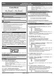
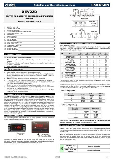
SinCPROBE PARAMETERStPPLPPPA4P20oPrttEotEDIGITAL INPUTSi1Pi1Fd1di2Pi2Fd2dALARMdAotdALPLMoPLoPPHYdMLMSHLSHSHYSHdFrCDISPLAYBand Offset:(-12.0 to 12.0°C; -21 to 21°F)PI band offset. It permits tomove the proportional band ofthe PI. With rS=0 the band isbetween [SEt to SEt+Pb].Integration time: (0 to 255s) PI integration time.Type of Pressure transducer: (420; 5V; LAn) it sets type of pressure transducer touse. 420 = 4 to 20mA pressure transducer; 5V = 0 to 5V ratiometric transducer; LAn =the pressure signal comes from another XEV module.Enable pressure probe sending in LAN: (n; Y) if LPP=Y the value of pressure readby device is sent in LAN. Only one device of the LAN can have LPP=Y.Probe value at 4mA or at 0V: (-1.0 to P20 bar; -14 to P20 psi) pressure valuemeasured by probe at 4mA or at 0V (related to PrM parameter).Probe value at 20mA or at 5V: (PA4 to 50.0 bar; PA4 to 725 psi) pressure valuemeasured by probe at 20mA or at 5V (related to PrM parameter).Pressure probe calibration: -12.0 to 12.0 bar; -174 to 174 psi.Type of temperature probe: (PtM; ntC) it allows to set the kind of probe used by theinstrument: PtM = PT1000 probe, ntC = NTC-US probe.Temperature probe calibration: -12.0 to 12.0°C; -21 to 21°F.Digital Input 1 (Free of voltage) digital input polarity: (cL, oP) CL = activated whenclosed; oP = activated when opened.Digital Input 1 (Free of voltage) digital input function: (CCL, rL) CCL = cooling call;rL = digital input activates relay.Digital Input 1 (Free of voltage) activation delay: (0 to 255 min) this activation delayis used only if digital input is configured as rL.Digital Input 2 (High voltage) digital input polarity: (CL, oP) CL = activated whenclosed; oP = activated when opened.Digital Input 2 (High voltage) digital input function: (CCL, rL) CCL = cooling call;rL = digital input activates relay.Digital Input 2 (High voltage) activation delay: (0 to 255 min) this activation delay isused only if digital input is configured as rL.Alarm delay after restarting regulation: (0.0 to 42min 00s, res. 10s) time betweendigital input activation (configured as CCL) and alarm signalling. The LSH alarm isalways signalled also during this time.Type of alarm signalled by relay: (ALL, SH, PrE, di) ALL = all alarm; SH = superheatalarm; PrE = pressure alarm; di = activation only when digital input configured as rL isactive.Lower Pressure Limit for superheat regulation: (PA4 to P20 bar; PA4 to P20 psi)when suction pressure comes down to LPL, the regulation is performed with a LPLfixed value for pressure. When suction pressure comes back to LPL, the normalpressure value is used (related to PrM parameter).Maximum Operating Pressure threshold: (LoP to P20bar; LoP to P20 psi) if suctionpressure exceeds maximum operating pressure value, the instrument signals thissituation with an alarm LED (related to PrM parameter).Lowest Operating Pressure: (PA4 to MoP bar; PA4 to MoP psi) if the suctionpressure comes down to this value, a low pressure alarm will be signalled with an alarmLED (related to PrM parameter).Pressure alarm Hysteresis: (0.1 to 5.0 bar, 1 to 72 psi) pressure hysteresis to disablealarm signalling.Delta MoP-LoP: (0 to 100%) when a MoP alarm occurs valve will close of the dMLpercentage every one second until MoP alarm is active. When LoP occurs, valve willopen of the dML percentage every one second until LoP alarm is active.Maximum SuperHeat alarm: (LSH to 80.0°C; LSH to 144°F) when superheat exceedsthis value, an high superheat alarm will be signalled after interval SHd.Lowest SuperHeat alarm: (0.0 to MSH°C; 0 to MSH°F) when superheat goes down tothis value a low superheat alarm is signalled after interval SHd.SuperHeat alarm Hysteresis: (0.0 to 25.5°C; 1 to 77°F) hysteresis for superheat alarmdeactivation.SuperHeat alarm activation delay: (0 to 255 s) when a superheat alarm occurs, thedelay time SHd have to expire before signalling this alarm.Fast-recovery Constant: (0 to 100 s) permits to increase integral time when SH isbelow the set-point. If FrC=0 fast recovery function is disabled.Lod Local display: (SH; PEr; P1; P2) SH = superheat; PEr = valve opening percentage;P1 = value of temperature measured; P2 = pressure measured by P2 probe.CF Temperature measurement units: (°C; °F) °C = Celsius degree; °F = Fahrenheitdegree. NOTE: by changing measurement unit, the regulation parameters have to becorrectly changed.PMU Pressure Measurement units: (bAr, PSi) bAr = bar; PSi = psi. NOTE: by changingmeasurement unit, the regulation parameters have to be correctly changed.rES Resolution (only °C): (dE; in) dE = decimal format; in = integer format.PrM Pressure visualization Mode: (rEL; AbS) rEL = relative pressure; AbS = absolutepressure. All pressure parameters depend on this parameter.CLP Cooling Percentage (read only): Display the cooling percentage.tP1 Temperature Probe value (read only): it shows temperature probe value from P1.PPr Pressure probe value (read only): it shows pressure probe value. The value dependson PrM.tP2 Temperature from P2 (read only): it shows temperature obtained from conversion ofpressure value.oPP Opening Percentage (read only): it shows the actual opening percentage of the valve.1592025920 <strong>XEV22D</strong> GB r3.0 02.02.2011.doc <strong>XEV22D</strong> 3/3d1Sd2SAdrModPtbrELPr2Free of voltage digital input State (read only): it shows the free of voltage digitalinput.High voltage digital input State (read only): it shows the high voltage digital inputstate.RS485 Serial Address: (1 to 247) Identifies the instrument address when connected toa ModBUS compatible monitoring system.ModBus: (AdU; Std) AdU = (Only for XWEB systems) in this case XEV andthermostatic controller are considered an alone instrument (it requires a custom libraryfor XWEB); Std = to use XEV in stand-alone mode, in this case normal Modbus-RTUprotocol is used.Parameters map: (read only) it identifies parameters map written by factory.Release Firmware: (read only) it shows firmware release.Second level menu.9. DIGITAL INPUTSThe device is provided with two digital inputs. One is free of voltage and the other is at high voltageand both can be configured as cooling call. In this way the cooling signal can come from instrumentswith direct load outputs or via instruments with output without voltage. One of these inputs must beconfigured as cooling call.10. FORCED OPENINGIf necessary, by changing FoP parameter it’s possible to force the valve opening. For example, bysetting FoP=50 the valve will be open at half of full scale. To disable this function it’s necessary toset FoP=nU (default value). The valve opening is enabled only when CCL digital input is enabled.11. ELECTRICAL CONNECTIONSThe instrument is provided with pluggable screw terminal block to connect cables with a cross sectionup to 2.5 mm 2 . Heat-resistant cables have to be used. Before connecting cables make sure the powersupply complies with the instrument’s requirements. Separate the probe cables from the power supplycables, from the outputs and the power connections. Do not exceed the maximum current allowed oneach relay, in case of heavier loads use a suitable external relay.11.1 PROBESAdvised temperature probe placement isillustrated in figure nearby. Between 0 and 180inclination degrees respect to horizontal pipesection. For suction pressure probe there aren’tany particular prescriptions12. RS485 SERIAL LINEAll models can be connected to the monitoring and supervising system XWEB3000. If Mod=Stdstandard ModBUS-RTU protocol is used, if Mod=AdU custom XWEB library is required. This lastconfiguration makes possible to use the same serial address of the thermostat that gives the coolingrequest to XEV. In this way, it’s possible to reduce the number of addresses used.13. HOW TO: USE THE HOT-KEY13.1 PROGRAM A HOT KEY FROM THE INSTRUMENT (UPLOAD)1) Program one controller with the front keypad.2) When the controller is ON, insert the “Hot-Key” and push UP button; the “uPL” messageappears followed a by flashing “End”.3) Push SET button and the “End” will stop flashing.4) Turn OFF the instrument, remove the “Hot-Key” and then turn it ON again.NOTE: the “Err” message is displayed in case of any failed programming operation. In this case, pushagain UP button if you want to restart the upload again or remove the “Hot-key” to abort the operation.13.2 PROGRAM AN INSTRUMENT USING A HOT KEY (DOWNLOAD)1) Turn OFF the instrument.2) Insert a pre-programmed “Hot-Key” into the 5-PIN connector and then turn the Controller ON.3) Automatically the parameter list present into the “Hot-Key” will be downloaded into theController memory. The “doL” message will blink during this operation, followed a by a flashing“End” label.4) After 10 seconds the instrument will restart working with the new parameters.5) Remove the “Hot-Key”.NOTE: the “Err” message is displayed in case of any failed programming operation. In this case, pushagain UP button if you want to restart the upload again or remove the “Hot-Key” to abort the operation.14. DISPLAY MESSAGESMess. Cause Outputs“nA”None of digital inputs configured as CCL areValve closedactivated“PF”The Ped time is elapsed and the regulation is Valve closed after PEd. There is a probestoppederror“P1” Temperature probe fault According to PEo and PEd.“P2” Pressure transducer fault According to PEo and PEd.“HSH” High superheat alarm By PI“LSH” Low superheat alarm Valve Closed“LPL” Low pressure limit see LPL parameter“MoP” Maximum Operating Pressure see dML parameter“LoP” Lowest Operating Pressure see dML parameter“StF” Start Function enabled see SFd parameter“StP” Regulation stop caused by Std and Sti Valve closed“EE” Memory error -14.1 ALARM RECOVERYProbe alarms “P1”, “P2” start few seconds after the fault in the probe; they automatically stop fewseconds after the probe restarts normal operation. Check connections before replacing the probe. Max.And min. Alarms “HSH”, “LSH”, “MoP” and “LoP” automatically stop as soon as the variable returns tonormal values.
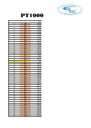
The instrument is provided with an internal check verifying memory integrity. Alarm “EE” will flash whena failure in the internal memory is detected. In such case call the service.15. TECHNICAL DATAHousing: self extinguishing ABS.Case: 4 DIN modules 70x135mm with male and female connectors; depth 60mm.Mounting: DIN RAIL mounted in an omega (3) din rail.Protection: IP20.Connections: pluggable screw terminal block 2.5 mm 2 wiring.Power supply: 24Vac/dc ±10%.Power absorption: depending on connected valve 20VA max.Display: three digits with icons, red LEDs, height 14.2 mm.Inputs:1 temperature probe:PT1000 probe: -50 to 110°C (-58 to 230°F).NTC probe: -40 to 110°C (-40 to 230°F).1 pressure transducer: 4 to 20mA or 0 to 5V.Digital inputs: 1 free of voltage.1 high voltage.Outputs for valve: bipolar or unipolar valves.Data storage: on the non-volatile memory (EEPROM).Kind of action: 1B.Pollution degree: normal.Software Class: A.Operating temperature: 0 to 55°C (32 to 131°F).Storage temperature: -25 to 60°C (-13 to 140°F).Relative humidity: 20 to 85% (no condensing).Resolution: 0.1°C or 1°F.Precision a 25°C (77°F): ±0.7°C ±1digit.16. STANDARD VALUESLabel Description Range Default LevelFtY Kind of gasR22; 134; 404; 407;410; 507; Co2404 Pr2Peo Probe Error opening percentage 0 to 100 % 50 Pr2Ped Probe Error delay before stopping regulation 0 to 239 s; on on Pr2tEU Type of Stepper motor uP; bP bP Pr2tEP Automatic Valve configuration 0 to 10 1 Pr2HFS Kind of driving HAF; FUL FUL Pr2LSt Minimum number of steps 0; USt (*10) See tEP Pr2USt Maximum number of steps LSt to 800 (*10) See tEP Pr2ESt Extra steps in closing phase 0 to 255 (*10) 0 Pr2Sr Step rate 10 to 600 step/s See tEP Pr2CPP Current per phase (only bipolar valves) 0 to 100 (*10mA) See tEP Pr2CHd Holding current per phase (only bipolar valves) 0 to 100 (*10mA) See tEP Pr2oPE Start opening Percentage 0 to 100 % 85 Pr2SFd Start Function duration 0.0 to 42min 00s, res. 10s 1.3 Pr2Sti Stop regulation interval 0.0 to 24h 00min, res. 10min 0 Pr2Std Stop duration 0 to 60 min 0 Pr2MnF Maximum opening percentage 0 to 100 % 100 Pr2FoP Forced Opening time-out 0 to 100 %; nU nU Pr2PI PARAMETERS (trained staff)Pb Proportional band[0.1 to 50.0°C][10.0°C][1 to 90°F][50°F]Pr2rS Band Offset[-12.0 to 12.0°C][0.0°C][-21 to 21°F][0°F]Pr2inC Integration time 0 to 255 s 120 Pr2PROBE PARAMETERStPP Type of pressure transducer 420; 5V; LAn 420 Pr2LPP Enable pressure probe sending in LAN n; Y n Pr2PA4Probe value at 4mA or at 0V (related to PrM [-1.0 to P20 bar] [-0.5 bar]parameter)[-14 to P20 psi][-7 psi]Pr2P20Probe value at 20mA or at 5V (related to PrM [ PA4 to 50.0 bar] [11.0 bar]parameter)[PA4 to 725 psi][159 psi]Pr2oPr Pressure probe calibration[-12.0 to 12.0 bar] [0.0 bar][-174 to 174 psi][0 psi]Pr2ttE type of temperature probe PT1000; ntC ntC Pr2otE Temperature probe calibration[-12.0 to 12.0°C][0.0°C][-21 to 21°F][0°F]Pr2DIGITAL INPUTSi1P Free of voltage digital input polarity CL; oP CL Pr2i1F Free of voltage digital input function CCL; rL CCL Pr2d1d Digital input 1 (free of voltage) activation delay 0 to 255 min 0 Pr2i2P Main voltage digital input polarity CL; oP CL Pr2i2F Main voltage digital input function CCL, rL CCL Pr2d2d Digital input 2 (Main voltage) activation delay 0 to 255 min 0 Pr2ALARMSdAo Alarm delay after restarting regulation 0.0 to 42min 00s, res. 10s 10.0 Pr2tdA Type of alarm signalled by relay ALL; SH; PrE; Di ALL Pr2LPLLower pressure limit for superheat regulation [PA4 to P20 bar] [-0.5 bar](related to PrM parameter)[PA4 to P20 psi][-7 psi]Pr2MoPMaximum operating pressure threshold (related [LoP to P20 bar] [11.0 bar]to PrM parameter)[LoP to P20 psi][159 psi]Pr2LoPMinimum suction pressure limit (related to PrM [PA4 to MoP bar] [-0.5 bar]parameter)[PA4 to MoP psi][-7 psi]Pr2PHy Pressure alarm Hysteresis[0.1 to 5.0 bar][0.1 bar][1 to 72 psi][1 psi]Pr2dML delta MoP-LoP 0 to 100% 30 Pr2MSH Maximum superheat alarm[LSH to 80.0°C][80.0°C][LSH to 176°F][144°F]Pr1LSH Lowest superheat alarm[0.0 to MSH°C][2.5°C][0 to MSH°F][2°F]Pr1SHY Superheat hysteresis[0.1 to 25.5°C][0.1°C][1 to 77°F][1°F]Pr2SHd Superheat alarm activation delay 0 to 255 s 120 Pr1FrC Fast-Recovery Constant 0 to 100 s 50 Pr2DISPLAYLod Local display SH; PEr; P1; P2 SH Pr1CF Temperature measurement units °C; °F[°C][°F]Pr2PMu Pressure measurement unit bAr; PSi bAr Pr2rES Resolution (only °C) dE; in dE Pr2PrM Type of pressure (Absolute / relative) rEL; AbS rEL Pr2CLP Cooling call percentage Read only - - - Pr2tP1 Temperature probe value Read only - -- Pr1PPr Pressure probe value Read only - - - Pr1tP2 Temperature converted from pressure probe Read only - - - Pr1oPP Acutal Opening percentage Read only - - - Pr1d1S Free of voltage digital input state Read only - - - Pr1d2S Main voltage digital input state Read only - - - Pr1Adr Serial address 1 to 247 1 Pr2Mod Modbus type Std; AdU Std Pr2Ptb Parameters map - - - - - - Pr2rEL Release software - - - - - - Pr2Pr2 Second level menu - - - - - - Pr11592025920 <strong>XEV22D</strong> GB r3.0 02.02.2011.doc <strong>XEV22D</strong> 4/4