XLR130 â XLR170 - Copyright Arctica Oy
XLR130 â XLR170 - Copyright Arctica Oy
XLR130 â XLR170 - Copyright Arctica Oy
- No tags were found...

You also want an ePaper? Increase the reach of your titles
YUMPU automatically turns print PDFs into web optimized ePapers that Google loves.
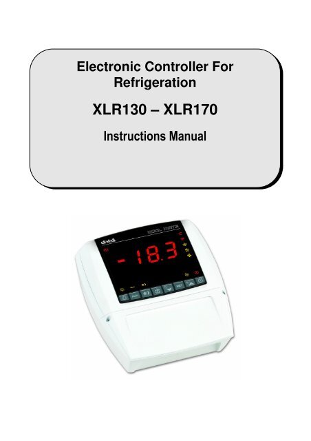
Electronic Controller ForRefrigeration<strong>XLR130</strong> – <strong>XLR170</strong>Instructions Manual
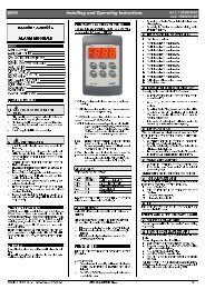
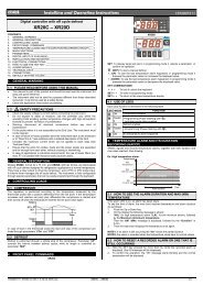
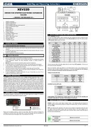
dIXELdIXEL Installing and Operating Instructions rel.2.0.0 - cod. 1592017000COOLOOLMATE<strong>XLR130</strong>C – <strong>XLR170</strong>CINDEXTo translate this manual in you language you can start from the manual of XW570L code: “1592009130 XW570L GB.doc” and translate the part inRED colour.1. GENERAL WARNING 32. GENERAL DESCRIPTION 33. CONTROLLING LOADS 34. KEYBOARD 55. REAL TIME CLOCK FUNCTION – ONLY FOR INSTRUMENTS WITH RTC 86. PARAMETER LIST 87. DIGITAL INPUTS 118. INSTALLATION AND MOUNTING 129. DIMENSIONS 1410. ELECTRICAL CONNECTIONS 1411. TTL SERIAL LINE 1412. HOW TO USE THE HOT KEY 1413. ALARM SIGNALS 1514. TECHNICAL DATA 1515. CONNECTIONS 1616. DEFAULT SETTING VALUES 171592017000 XLR 130-170 GB r2.0 08.09.2006.doc XL130 - <strong>XLR170</strong> 2/19
dIXELdIXEL Installing and Operating Instructions rel.2.0.0 - cod. 15920170001. GENERAL WARNING1.1 PLEASE READ BEFORE USING THIS MANUAL• This manual is part of the product and should be kept near the instrument for easy and quick reference.• The instrument shall not be used for purposes different from those described hereunder. It cannot be used as a safety device.• Check the application limits before proceeding.1.2 SAFETY PRECAUTIONS• Check the supply voltage is correct before connecting the instrument.• Do not expose to water or moisture: use the controller only within the operating limits avoiding sudden temperature changes with highatmospheric humidity to prevent formation of condensation• Warning: disconnect all electrical connections before any kind of maintenance.• Fit the probe where it is not accessible by the End User. The instrument must not be opened.• In case of failure or faulty operation send the instrument back to the distributor or to “Dixell S.p.A.” (see address) with a detailed description ofthe fault.• Consider the maximum current which can be applied to each relay (see Technical Data).• Ensure that the wires for probes, loads and the power supply are separated and far enough from each other, without crossing or intertwining.• In case of applications in industrial environments, the use of mains filters (our mod. FT1) in parallel with inductive loads could be useful.2. GENERAL DESCRIPTIONModels <strong>XLR130</strong> and <strong>XLR170</strong>, 210x230mm format, are microprocessor based controllers suitable for applications on medium or low temperaturerefrigerating units. They are provided with four (<strong>XLR130</strong>) or six (<strong>XLR170</strong>) relay outputs to control compressor, defrost - which can be either electricalor hot gas (<strong>XLR170</strong>) - the evaporator fans (<strong>XLR170</strong>), the lights, the alarm and an auxiliary output. They are also provided with three NTC or PTCprobe inputs, one for temperature control, one to control the defrost end temperature of the evaporator and the third, optional, for the display. Thereare two digital inputs (free contact) for the door switch and configurable by parameter.The standard TTL output allows the user to connect, by means of a TTL/RS485 external module, a ModBUS-RTU compatible monitoring system andto programme the parameter list with the “Hot Key”.Each model in the XLR100 can be provided with a Real Time Clock which allows programming of up to eight daily defrost cycles, divided intoholidays and workdays. A “Day and Night” function with two different set points is fitted for energy saving.3. CONTROLLING LOADS3.1 THE COMPRESSORThe regulation is performed according to the temperature measured by the thermostat probe with a positive differential from the set point: if thetemperature increases and reaches set point plus differential the compressor is started and then turned off when the temperature reaches the setpoint value again.In case of fault in the thermostat probe the start and stop of the compressor are timed through parameters “COn” and “COF”.3.2 FAST FREEZINGWhen defrost is not in progress, it can be activated the keypad by holding the o key pressed for about 3 seconds. The compressor operates incontinuous mode for the time set through the “CCt” parameter. The cycle can be terminated before the end of the set time using the same activationkey, o for about 3 seconds.3.3 DEFROST3.3.1 <strong>XLR130</strong> – TIMED DEFROSTThe defrost interval is controlled by means of parameter “EdF”:- with EdF=in the defrost is made every “IdF” time,- with EdF=Sd the interval “IdF” is calculate through Smart Defrost algorithm (the counter is increased only when the compressor is ON).- with real time clock present EdF can be set to “rtc”, In this case, the defrost is made in real time depending on the hours set in the parametersLd1..Ld8 on workdays and in Sd1…Sd8 in holidays;Defrost is performed through a simple stop of the compressor. Parameter “IdF” controls the interval between defrost cycles, while its length iscontrolled by parameter “MdF”.3.3.2 <strong>XLR170</strong> – HEATER OR HOT GAS DEFROSTThree defrost modes are available through the “tdF” parameter: defrost with electrical heater (tdF=rE),defrost(tdF=rt).The defrost interval is controlled by means of parameter “EdF”:hot gas (tdF=in), or thermostatic1592017000 XLR 130-170 GB r2.0 08.09.2006.doc XL130 - <strong>XLR170</strong> 3/19
dIXELdIXEL Installing and Operating Instructions rel.2.0.0 - cod. 1592017000- with EdF=in the defrost is made every “IdF” time,- with EdF=Sd the interval “IdF” is calculate through Smart Defrost algorithm (the counter is increased only when the compressor is ON).- with real time clock present EdF can be set to “rtc”. In this case, the defrost is made in real time depending on the hours set in the parametersLd1..Ld8 on workdays and in Sd1…Sd8 in holidays;At the end of defrost the drip time is controlled through the “Fdt” parameter.3.4 CONTROL OF EVAPORATOR FANS (<strong>XLR170</strong> OR <strong>XLR130</strong> WITH OA1=FAN)The fan control mode is selected by means of the “FnC” parameter:C-n fans will switch ON and OFF with the compressor and not run during defrost;C-y fans will switch ON and OFF with the compressor, also during defrostAfter defrost, there is a timed fan delay allowing for drip time, set by means of the “Fnd” parameter.O-n fans will run continuously and not run during defrost;O-y fans will run continuously also during defrostAn additional parameter “FSt” provides the setting of temperature, detected by the evaporator probe, above which the fans are always OFF. This canbe used to make sure circulation of air only if his temperature is lower than set in “FSt”.3.5 AUXILIARY OUTPUT CONFIGURATION - TERM. 15-16, PAR. OA1The functioning of the auxiliary relay (terminals. 15-16) can be set by the oA1 parameter, according to the kind of application. In the followingparagraph the possible setting:3.5.1 <strong>XLR130</strong>: forced air application, normal temperature -oA1= FanParameters involved:- FnC Fan operating mode; - Fnd Fan delay after a defrost- FSt Fan stop temperature; - FAP Probe for fan managementWith this setting the auxiliary relay works as fan relay. See par. 3.4 “Control of evaporator fans”.NOTE: if FAP = nP (no probe), the relay will be activated according to the setting of FnC parameter independently from the temperature ofevaporator.3.5.2 Auxiliary relay - oA1= AUSWith oA1=AUS, two kinds of working are available.A. The AUX relay is activated only by keyboardSet oA1 =AUS and ArP= nP (no probe for auxiliary output).In this case the relay 15-16 can be activated only by pushing the AUX button of the keyboard.B. Auxiliary thermostat (I.E.. anti condensing heater) with the possibility of switching it on and off also by keyboardParameters involved:- ACH Kind of regulation for the auxiliary relay: heating /cooling;- SAA Set point for auxiliary relay- ArP Probe for auxiliary relayBy means of these 3 parameters the functioning of the auxiliary relay can be set.. The differential is given by the Hy parameter.The auxiliary relay can be switched on also by the AUX button. In this case it remains on till it’s manually switched off.The defrost doesn’t affect the status of auxiliary relay.3.5.3 on/off relay - oA1 = onFIn this case the relay is activated when the controller is turned on and de-activated when the controller is turned off..3.5.4 <strong>XLR170</strong>: Second defrost relay for applications with 2 evaporators – oA1 = dF2Parameters involved:- dtS end defrost temperature for second defrost relay;- MdS maximum defrost duration for second defrost relay;- dSP probe selection for second defrostWith 2 evaporators the regulation restarts when both the defrosts are finished.3.5.5 Second compressor – oA1 = cP2In this case the controller can manage 2 compressors or a 2 step compressor.Functioning: the 2 nd compressor is activated after the fist compressor with a delay set in the Ac1 parameter (seconds). Both compressor areturned off at the same time.1592017000 XLR 130-170 GB r2.0 08.09.2006.doc XL130 - <strong>XLR170</strong> 4/19
dIXELdIXEL Installing and Operating Instructions rel.2.0.0 - cod. 1592017000If cco=AL compressors are switched on by turn.Parameters involved:- cco Compressor activation: type of sequence: by turn or in sequence;- Ac1 Second compressor activation delay (seconds);4. KEYBOARDPanic LEDTo display and modify target set point; in programming mode it selects a parameter or confirms an operation.By holding it pressed for 3s when max or min temperature is displayed, it will be erased.Only for models with RTC: by pressing it when the current time is displayed, it allows the User to re-set the current time and threeholidays.To see the max. stored temperature; in programming mode it browses the parameter codes or increases the displayed value. Byholding it pressed for 3s the fast freezing cycle is started.To see the min stored temperature; in programming mode it browses the parameter codes or decreases the displayed value.Only for models with RTC: by holding it pressed for 3s the current time is displayed and it permits the User to enter Energy saving,Defrost and Clock parameter menu.By holding it pressed for 3s the defrost is started.Only for models with RTC by pressing it when the current time is displayed, it allows the User to set defrost times.KEY COMBINATIONSSwitch ON and OFF the cold room light.To start and stop Energy Saving function.Only for models with RTC: by holding it pressed for 6s, the holiday function is started or stopped.By pressing it when the current time is displayed, it allows the User to set Energy Saving times.If oA1 = AUS, it switches ON and OFF the auxiliary output.To switch ON and OFF the instrument.+To lock and unlock the keyboard.+To enter the programming mode.+To exit the programming mode.1592017000 XLR 130-170 GB r2.0 08.09.2006.doc XL130 - <strong>XLR170</strong> 5/19
dIXELdIXEL Installing and Operating Instructions rel.2.0.0 - cod. 15920170004.1 USE OF LEDSEach LED function is described in the following table.LED MODE Function°C ON Celsius degrees display°C FLASHING Programming phase°F ON Fahrenheit degrees displayON The compressor is runningFLASHING - Programming Phase (flashing with LED )- Anti-short cycle delay enabledON The fan is runningFLASHINGONFLASHINGONONAUX ONONONONProgramming Phase (flashing with LED )The defrost is enabledDrip time in progressThe Fast Freezing cycle is enabled- ALARM signal- In “Pr2” indicates that the parameter is also present in “Pr1”Auxiliary output (15-16) on (oA1=AUS).Energy saving onLight onThe instrument is off4.2 4.2 HOW TO SEE THE MIN TEMPERATURE1. Press and release the n key.2. The “Lo” message will be displayed followed by the minimum temperature recorded.3. By pressing the n key or waiting for 5s the normal display will be restored.4.3 4.3 HOW TO SEE THE MAX TEMPERATURE1. Press and release the o key.2. The “Hi” message will be displayed followed by the maximum temperature recorded.3. By pressing the o key or waiting for 5s the normal display will be restored.4.4 4.4 HOW TO RESET THE MAX AND MIN TEMPERATURE RECORDEDTo reset the stored temperature, when max or min temperature is displayed :1. Press SET key until “rST” label starts blinking.N.B. After the installation RESET the temperature stored .4.5 HOW TO SEE AND MODIFY THE SET POINT1. Push and immediately release the SET key: the display will show the Set point value;2. The “°C” LED starts blinking;3. To change the Set value push the o or n arrows within 10s.4. To memorise the new set point value push the SET key again or wait 10s.4.6 TO START A MANUAL DEFROSTPush the DEF key for more than 2 seconds and a manual defrost will start.4.7 TO ENTER IN PARAMETERS LIST “PR1”To enter the parameter list “Pr1” (user accessible parameters) operate as follows:1. Enter the Programming mode by pressing the Set and DOWN key for few seconds (“°C” LED starts blinking).2. The instrument will show the first parameter present in “Pr1”+1592017000 XLR 130-170 GB r2.0 08.09.2006.doc XL130 - <strong>XLR170</strong> 6/19
dIXELdIXEL Installing and Operating Instructions rel.2.0.0 - cod. 15920170004.8 TO ENTER IN PARAMETERS LIST “PR2”To access parameters in “Pr2”:1. Enter the “Pr1” level.2. Select “Pr2” parameter and press the “SET” key.3. The “PAS” flashing message is displayed, shortly followed by “0 - -” with a flashing zero.4. Use o or n to input the security code in the flashing digit; confirm the figure by pressing “SET”.The security code is “321“.5. If the security code is correct the access to “Pr2” is enabled by pressing “SET” on the last digit.Another possibility is the following: after switching ON the instrument the user can push Set and DOWN keys within 30 seconds.NOTE: each parameter in “Pr2” can be removed or put into “Pr1” (user level) by pressing “SET” + n. When a parameter is present in “Pr1” “decimalpoint “ is on.4.9 HOW TO CHANGE THE PARAMETER VALUE1. Enter the Programming mode.2. Select the required parameter with o or n.3. Press the “SET” key to display its value (“°C” LED starts blinking).4. Use o or n to change its value.5. Press “SET” to store the new value and move to the following parameter.To exit: Press SET + UP or wait 15s without pressing a key.NOTE: the new programming is stored even when the procedure is exited by waiting the time-out.4.10 HOW TO LOCK THE KEYBOARD1. Keep the o and n keys pressed together for more than 3 s the o and n keys.2. The “POF” message will be displayed and the keyboard is locked. At this point it is only possible the viewing of the set point or theMAX o Min temperature stored and to switch ON and OFF the light and the auxiliary output.+TO UNLOCK THE KEYBOARDKeep the o and n keys pressed together for more than 3s.4.11 ON/OFF FUNCTIONBy pushing the ON/OFF key, the instrument shows “OFF” for 5 sec. and the ON/OFF LED is switched ON.During the OFF status, all the relays are switched OFF and the regulations are stopped; if a monitoring system is connected, it does notrecord the instrument data and alarms.N.B. During the OFF status the Light and AUX buttons are active.4.12 TO SEE THE PROBE VALUES1. Enter in “Pr1” level.2. Select “dP1” parameter for probe 1, “dP2” parameter for probe 2, “dP3” parameter for probe 3, with o or n.3. Press the “SET” key to see the value of the selected probe.4. Press “SET” to move to the following parameter.1592017000 XLR 130-170 GB r2.0 08.09.2006.doc XL130 - <strong>XLR170</strong> 7/19
dIXELdIXEL Installing and Operating Instructions rel.2.0.0 - cod. 15920170005. REAL TIME CLOCK FUNCTION – ONLY FOR INSTRUMENTS WITH RTC5.1 TO SEE THE CURRENT TIME AND DAY1. Push the n key for more than 3 seconds2.eLED switches ON and the following messages are displayed:Hur (hour); Min (Minute); dAY (day)3. To exit push n key or wait 5 seconds5.2 TO SET THE TIME AND THE WEEKLY HOLIDAYSfollowed by1. Push the n key for more than 3 seconds2.eLED switches ON and the current time is displayed.3. By pushing the SET key, the eLED will start flashing and setting the current hour, minutes, day and the weekly holidays (upto 3) will be possible.4. To exit, press SET + UP or wait 15s without pressing any key.5.3 TO SET THE DEFROST TIMESfollowed by1. Push the n key for more than 3 seconds2.eLED switches ON and the current time is displayed.3. By pushing DEF key, the DEF led will start flashing and setting defrost time will be possible.4. To exit, press SET + UP or wait 15s without pressing any key.5.4 TO SET THE ENERGY SAVING TIMESfollowed by1. Push the n key for more than 3 seconds2.eLED switches ON and the current time is displayed.3. By pushing the ES key, the ES led will start flashing and setting Energy Saving time will be possible.4. To exit, press SET + UP or wait 15s without pressing any key.5.5 TO START HOLIDAY FUNCTION BY USING THE KEYBOARD1. Push the ES key for more than 6 seconds until the label “Hd” is shown.2.eLED will start to blink slower than during time programming and the regulators will follow holiday times.3. Push the ES key for more than 6 seconds to start normal functioning again.6. PARAMETER LISTREGULATIONHy Differential: (0,1÷25,5°C; 1÷45°F): Intervention differential for set point, always positive. Compressor Cut IN is Set Point Plus Differential (Hy).Compressor Cut OUT is when the temperature reaches the set point.LS Minimum set point limit: (-50,0°C÷SET; -58°F÷SET) Sets the minimum acceptable value for the set point.US Maximum set point limit: (SET÷110°C; SET÷230°F) Set the maximum acceptable value for set point.odS Outputs activation delay at start up: (0÷255 min) This function is enabled at the initial start up of the instrument and inhibits any outputactivation for the period of time set in the parameter. (AUX and Light can work)cco Compressors: kind of activation. Used only if oA1 =cP2: SE = sequential activation; AL = by turn activationAC Anti-short cycle delay: (0÷30 min) interval between the compressor stop and the following restart.Ac1 2 nd compressor delay at start up (0÷255s) Time interval between the switching on of the first compressor and the second one. (0÷225s).CCt Thermostat override: (0min ÷23h 50min) allows to set the length of the continuous cycle. Can be used, for instance, when the room is filledwith new products.Con Compressor ON time with faulty probe: (0÷255 min) time during which the compressor is active in case of faulty thermostat probe. WithCOn=0 compressor is always OFF.1592017000 XLR 130-170 GB r2.0 08.09.2006.doc XL130 - <strong>XLR170</strong> 8/19
dIXELdIXEL Installing and Operating Instructions rel.2.0.0 - cod. 1592017000COF Compressor OFF time with faulty probe: (0÷255 min) time during which the compressor is off in case of faulty thermostat probe. WithCOF=0 compressor is always active.CH Type of action - Only for <strong>XLR130</strong>: CL = cooling; Ht = heating..DISPLAYCF Temperature measurement unit: °C = Celsius; °F = Fahrenheit . When the measurement unit is changed the SET point and the values of theregulation parameters have to be modifiedrES Resolution (for °C): (in = 1°C; de = 0,1°C) allows decimal point display. dE = 0,1°C; in = 1 °CLod Local display : select which probe is displayed by the instrument: P1 = Thermostat probe; P2 = Evaporator probe; P3 = auxiliary probe1r2 = difference between P1 and P2 (P1-P2)DEFROSTtdF Defrost type Only for <strong>XLR170</strong>: rE = electrical heater (Compressor OFF); rT = thermostat defrost. During the defrost time “MdF”, the heaterswitches On and OFF depending on the evaporator temperature and “dtE” value; in = hot gas (Compressor and defrost relays ON)EdF Defrost mode:rtc = Real Time Clock mode. Defrost time follows Ld1÷Ld8 parameters on workdays and Sd1÷Sd8 on holidays. Available only if the ’RTCoption is presentin = interval mode. The defrost starts when the time “Idf” is expired.Sd = Smartfrost mode. The time IdF (interval between defrosts) is increased only when the compressor is running (even non consecutively)and only if the evaporator temperature is less than the value in "SdF” (set point for SMARTFROST).SdF Set point for SMARTFROST: (-30÷30 °C/ -22÷86 °F) evaporator temperature which allows the IdF counting (interval between defrosts) inSMARTFROST mode.dtE Defrost termination temperature Only for <strong>XLR170</strong>: (-50,0÷110,0°C; -58÷230°F) (Enabled only when the evaporator probe is present) setsthe temperature measured by the evaporator probe which causes the end of defrost.dtS Defrost termination temperature 2 nd evaporator – Only for <strong>XLR170</strong> if oA1=dF2 : (-50,0÷110,0°C; -58÷230°F) sets the temperaturemeasured by the 2 nd evaporator probe which causes the end of defrost.IdF Interval between defrosts: (1÷120h) Determines the time interval between the beginning of two defrost cycles.MdF (Maximum) duration of defrost: (0÷255 min) When P2P = n, no evaporator probe, it sets the defrost duration, when P2P = y, defrost endbased on temperature, it sets the maximum length for defrost.MdS (Maximum) duration of defrost for 2 nd evaporator – Only for <strong>XLR170</strong> if oA1=dF2: (0÷255 min) It sets the maximum duration of the defrostfor 2 nd evaporator.dFd Display during defrost: rt = real temperature; it = temperature at the defrost start; Set = set point; dEF = “dEF” label; dEG = “dEG” label;dAd Defrost display time out: (0÷255 min) Sets the maximum time between the end of defrost and the restarting of the real room temperaturedisplay.dSd Start defrost delay - Only for <strong>XLR170</strong>: ( 0÷99min) This is useful when different defrost start times are necessary to avoid overloading theplant.Fdt Drain down time: (0÷60 min.) time interval between reaching defrost termination temperature and the restoring of the control’s normaloperation. This time allows the evaporator to eliminate water drops that might have formed due to defrost.dPO First defrost after start-up:y = Immediately; n = after the IdF timedAF Defrost delay after fast freezing: (0min÷23h 50min) after a Fast Freezing cycle, the first defrost will be delayed for this time.dFP End defrost probe for first evaporator selection – Only for <strong>XLR170</strong>: nP = no probe, defrost by time. Duration set by MdF parameter; P1 =Probe 1 (thermostat probe); P2 = Probe 2 (evaporator probe); P3 = Probe 3 (display probe).dSP End defrost probe for second evaporator selection – Only for <strong>XLR170</strong>: nP = no probe, defrost by time. Duration set by MdS parameter; P1= Probe 1 (thermostat probe); P2 = Probe 2 (evaporator probe); P3 = Probe 3 (display probe).FANSFnC Fan operating mode: C-n = running with the compressor, OFF during the defrost;C-y = running with the compressor, ON during the defrost;O-n = continuous mode, OFF during the defrost;O-y = continuous mode, ON during the defrost;Fnd Fan delay after defrost: (0÷255 min) The time interval between the defrost end and evaporator fans start.FSt Fan stop temperature: (-50÷110°C; -58÷230°F) setting of temperature, detected by evaporator probe, above which the fan is always OFF.dSP Fan probe selection: nP = no probe, fans act according to the Fnc parameter, without temperature control set in FSt parameter; P1 = Probe 1(Thermostat probe); P2 = Probe 2 (evaporator probe); P3 = Probe 3 (display probe).ALARMSALC Temperature alarm configuration: rE = High and Low alarms related to Set Point;Ab = High and low alarms related to the absolute temperature.ALU High temperature alarm setting: ( ALC= rE, 0 ÷ 50°C or 90°F; ALC= Ab, ALL ÷ 110°C or 230°F)when this temperature is reached and after the ALd delay time the HA alarm is enabled.ALL Low temperature alarm setting: ( ALC = rE , 0 ÷ 50 °C or 90°F; ALC = Ab , - 50°C or -58°F ÷ ALU)when this temperature is reached and after the ALd delay time, the LA alarm is enabled,.AFH Temperature alarm and fan differential: (0,1÷25,5°C; 1÷45°F) Intervention differential for temperature alarm set point and fan regulation setpoint, always positive.1592017000 XLR 130-170 GB r2.0 08.09.2006.doc XL130 - <strong>XLR170</strong> 9/19
dIXELdIXEL Installing and Operating Instructions rel.2.0.0 - cod. 1592017000ALd Temperature alarm delay: (0÷255 min) time interval between the detection of an alarm condition and the corresponding alarm signalling.dAO Delay of temperature alarm at start-up: (0min÷23h 50min) time interval between the detection of the temperature alarm condition after theinstrument power on and the alarm signalling.EdA Alarm delay at the end of defrost: (0÷255 min) Time interval between the detection of the temperature alarm condition at the end of defrostand the alarm signalling.dot Delay of temperature alarm after closing the door : (0÷255 min) Time delay to signal the temperature alarm condition after closing the door.doA Open door alarm delay:(0÷254min,nu) delay between the detection of the open door condition and its alarm signalling: the flashing message“dA” is displayed. If doA=nu the door alarm will be not signalled.rrd Output restart after door open alarm doA: no = outputs unchanged after doA alarm; yES = outputs restart after doA alarm;tbA Buzzer and alarm relay silencing: by pushing one of the keypad buttons.n= Only the Buzzer is silenced; y= Buzzer and relay are silenced.nPS Pressure switch number: (0 ÷15) Number of activation of the pressure switch, during the “did” interval, before signalling the alarm event (I2F=PAL).PROBE INPUTSOt Thermostat probe calibration: (-12.0÷12.0°C/ -21÷21°F) allows to adjust possible offset of the thermostat probe.OE Evaporator probe calibration – Only for <strong>XLR170</strong>: (-12.0÷12.0°C/ -21÷21°F) allows to adjust possible offsets of the evaporator probe.O3 Auxiliary probe calibration: (-12.0÷12.0°C/ -21÷21°F) allows to adjust possible offsets of the evaporator probe.P2P Evaporator probe presence - Only for <strong>XLR170</strong>:n= not present: the defrost stops only by time; y= present: the defrost stops by temperature and time.P3P Auxiliary probe presence (display): n= not present; y= present.Pbr Thermostat probe selection P1 = Probe 1 (Thermostat probe); P2 = Probe 2 (evaporator probe); P3 = Probe 3 (display probe); 1r2 = P1-P2.HES Temperature increase during the Energy Saving cycle : (-30÷30°C / -54÷54°F) sets the increasing value of the set point during the EnergySaving cycle.DIGITAL INPUTSodc Compressor and fan status when open door:no = normal; Fan = Fan OFF; CPr = Compressor OFF; F_C = Compressor and fan OFF.I1P Door switch input polarity: CL : the digital input is activated by closing the contact; OP : the digital input is activated by opening the contact.I2P Configurable digital input polarity: CL : the digital input is activated by closing the contact;OP : the digital input is activated by opening the contactI2F Digital input operating mode: configure the digital input function: EAL = generic alarm; bAL = serious alarm mode; PAL = Pressure switch;dFr = Start defrost; AUS = Relay AUX actuation; Es = Energy Saving; onF = remote On/OFF; HdF = Holiday function.did Time interval/delay for digital input alarm:(0÷255 min.) Time interval to calculate the number of the pressure switch activation whenI2F=PAL. If I2F=EAL or bAL (external alarms), “did” parameter defines the time delay between the detection and the successive signalling ofthe alarm.AUXILIARY RELAY CONFIGURATIONoA1 Auxiliary relay configuration (terminals 15-16): dEF = Not set it; ALr = alarm; FAn = fans; Lig =light; AUS = auxiliary; onF = on/off; dF2 =second defrost (only for <strong>XLR170</strong>), cP2 = second compressor (only for <strong>XLR170</strong>).AUXILIARY THERMOSTAT CONFIGURATION (terms. 15-16) – OA1 = AUSACH Kind of regulation for auxiliary relay: Ht = heating; CL = coolingSAA Set Point for auxiliary relay: (-50,0÷110,0°C; -58÷230°F) it defines the room temperature setpoint to switch auxiliary relay.ArP Probe selection for auxiliary: nP = no probe, the auxiliary relay is switched only by button; P1 = Probe 1 (Thermostat probe); P2 = Probe 2(evaporator probe); P3 = Probe 3 (display probe).AoP Alarm relay polarity (terms. 29-30-31): oP = 29-30 terminals open with alarm; cL = 29-30 terminals close with alarmTO SET CURRENT TIME AND WEEKLY HOLIDAYS ( 3SEC followed by ) – Only for models with RTCHur Current hour (0 ÷ 23 h)Min Current minute (0 ÷ 59min)dAY Current day (Sun ÷ SAt)Hd1 First weekly holiday (Sun ÷ nu) Set the first day of the week which follows the holiday times.Hd2 Second weekly holiday (Sun ÷ nu) Set the second day of the week which follows the holiday times.Hd3 Third weekly holiday (Sun ÷ nu) Set the third day of the week which follows the holiday times.N.B.Hd1,Hd2,Hd3 can be set also as “nu” value (Not Used).TO SET ENERGY SAVING TIMES (3SEC. afterward )ILE Energy Saving cycle start during workdays: (0 ÷ 23h 50 min.) During the Energy Saving cycle the set point is increased by the value inHES so that the operation set point is SET + HES.dLE Energy Saving cycle length during workdays: (0 ÷ 24h 00 min.) Sets the duration of the Energy Saving cycle on workdays.1592017000 XLR 130-170 GB r2.0 08.09.2006.doc XL130 - <strong>XLR170</strong> 10/19
dIXELdIXEL Installing and Operating Instructions rel.2.0.0 - cod. 1592017000ISE Energy Saving cycle start on holidays. (0 ÷ 23h 50 min.)dSE Energy Saving cycle length on holidays (0 ÷ 24h 00 min.)HES Temperature increase during the Energy Saving cycle (-30÷30°C / -54÷54°F) sets the increasing value of the set point during the EnergySaving cycle.TO SET DEFROST TIMES (3SEC. afterward )Ld1÷Ld8 Workday defrost start (0 ÷ 23h 50 min.) These parameters set the beginning of the eight programmable defrost cycles during workdays.Ex. When Ld2 = 12.4 the second defrost starts at 12.40 during workdays.Sd1÷Sd8 Holiday defrost start (0 ÷ 23h 50 min.) These parameters set the beginning of the eight programmable defrost cycles on holidays. Ex.When Sd2 = 3.4 the second defrost starts at 3.40 on holidays.N.B. :To disable a defrost cycle set it to “nu”(not used). Ex. If Ld6=nu ; the sixth defrost cycle is disabledOTHERAdr RS485 serial address (1÷247): Identifies the instrument address when connected to a ModBUS compatible monitoring system.PbC Probe selection: (Ptc=PTC probe; ntc=NTC probe). It allows to select the kind of probe.Rel Release software: (read only) Software version of the microprocessor.Ptb Parameter table: (read only) it shows the original code of the dIXEL parameter map.dP1 Probe 1 temperature (thermostat): it displays the temperature detected by the thermostat probe.dP2 Probe 2 temperature (evaporator): it displays the temperature detected by the evaporator probe.dP3 Probe 3 temperature (display): it displays the temperature detected by the display probe.Pr2 Access to the protected parameter list (read only).7. DIGITAL INPUTSThe Wing series can support up to 2 free contact digital inputs. One is always configured as door switch, the second is programmable in sevendifferent configurations by the “I2F” parameter.7.1 DOOR SWITCH INPUTIt signals the door status and the corresponding relay output status through the “odc” parameter:no = normal (any change);Fan = Fan OFF;CPr = Compressor OFF;F_C = Compressor and fan OFF.Since the door is opened, after the delay time set through parameter “dOA”, the alarm output is enabled and the display shows the message “dA”.The alarm stops as soon as the external digital input is disabled again. During this time and then for the delay “dot” after closing the door, the highand low temperature alarms are disabled.7.2 CONFIGURABLE INPUT - GENERIC ALARM (EAL)As soon as the digital input is activated the unit will wait for “did” time delay before signalling the “EAL” alarm message. The outputs status don’tchange. The alarm stops just after the digital input is de-activated.7.3 CONFIGURABLE INPUT - PANIC ALARM (i2F = PAn)As soon as the digital input is activated the unit displays the “PAn” alarm message, the alarm buzzer, relay and panic LED are activated. The otheroutputs status don’t change. The alarm stops just after the digital input is de-activated.7.4 CONFIGURABLE INPUT - SERIOUS ALARM MODE (BAL)When the digital input is activated, the unit will wait for “did” delay before signalling the “BAL” alarm message. The relay outputs are switched OFF.The alarm will stop as soon as the digital input is de-activated.7.5 CONFIGURABLE INPUT - PRESSURE SWITCH (PAL)If during the interval time set by “did” parameter, the pressure switch has reached the number of activation of the “nPS” parameter, the “PAL”pressure alarm message will be displayed. The compressor and the regulation are stopped. When the digital input is ON the compressor is alwaysOFF.7.6 CONFIGURABLE INPUT - START DEFROST (DFR)It executes a defrost if there are the right conditions. After the defrost is finished, the normal regulation will restart only if the digital input is disabledotherwise the instrument will wait until the “Mdf” safety time is expired.7.7 CONFIGURABLE INPUT - RELAY AUX ACTUATION (AUS)This function allows to turn ON and OFF the auxiliary relay by using the digital input as external switch.1592017000 XLR 130-170 GB r2.0 08.09.2006.doc XL130 - <strong>XLR170</strong> 11/19
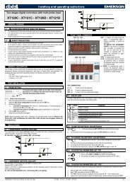
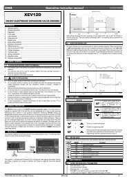
dIXELdIXEL Installing and Operating Instructions rel.2.0.0 - cod. 15920170007.8 CONFIGURABLE INPUT - ENERGY SAVING (ES)The Energy Saving function allows to change the set point value as the result of the SET+ HES (parameter) sum. This function is enabled until thedigital input is activated.7.9 CONFIGURABLE INPUT - REMOTE ON/OFF (ONF)This function allows to switch ON and OFF the instrument.7.10 CONFIGURABLE INPUT - HOLIDAY FUNCTION (HDF)In Holiday function Energy saving and defrost cycles follow holiday times. (Sd1…Sd8)7.11 DIGITAL INPUTS POLARITYThe digital inputs polarity depends on “I1P” and “I2P” parameters.CL : the digital input is activated by closing the contact, OP : the digital input is activated by opening the contact8. INSTALLATION AND MOUNTINGThe temperature range allowed for correct operation is 0 - 60 °C. Avoid places subject to strong vibrations, corrosive gases, excessive dirt orhumidity. The same recommendations apply to probes. Let the air circulate by the cooling holes.Thanks to the case, <strong>XLR130</strong> and <strong>XLR170</strong> models can be panel or wall mounted. See the following instructions for details.FGFGDECBDACBAFIG. 1FIG. 287 230H130IMAX28MAX 37120210FIG. 31592017000 XLR 130-170 GB r2.0 08.09.2006.doc XL130 - <strong>XLR170</strong> 12/19
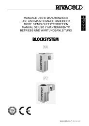
dIXELdIXEL Installing and Operating Instructions rel.2.0.0 - cod. 1592017000A020061106.44°Fig. 60 18172Fig. 4190061261200192.5185R 58.5106.44°8.5R 5019041861117914.5175.522.5167.529.5 160.55Fig. 58.1 WALL MOUNTING1. Unscrew the 4 frontal screws (Fig. 1, A, B, F, G) and remove the cover (Fig. 1, C).2. Unscrew the 2 screws (Fig. 1, D, E) that keep connected the frontal and lower parts of Cool Mate and separate the 2 parts.3. Make the proper holes for cablepresses or pipepresses using the centres signed in the bottom cover of the Cool Mate, (Fig. 3, H, I, ). Thenmake 3 holes in the wall, as indicated in (Fig. 3, L, M, N), to fix the Cool Mate4. Fix the cablepresses and the pipepresses..5. Insert the wall-nugs, contained in the kit, into the holes made in the wall. Then use the o-rings and fix the back part of the Cool Mate (Fig. 3, L,M, N) by means of the 3 screws to the wall itself.6. Insert the wiring cables in cablepresses or in the pipepresses.7. Mount the frontal part using the previous 4 screws Fig. 1, D, E, F, G. (do not press excessively in order to avoid plastic deformation).8. After connecting the wires to the terminal blocks close the cover (Fig. 2, c) and fix it by the screws.1592017000 XLR 130-170 GB r2.0 08.09.2006.doc XL130 - <strong>XLR170</strong> 13/19
dIXELdIXEL Installing and Operating Instructions rel.2.0.0 - cod. 15920170008.2 PANEL MOUNTING1. Make a hole in the panel with dimensions described in Fig. 4 (simplified) or Fig. 5 (completed)2. Unscrew the 4 frontal screws (Fig. 1, A, B, F, G) and remove the cover (Fig. 1, C).3. Unscrew the 2 screws (Fig. 1, D, E) that keep connected the frontal and lower parts of Cool Mate and separate the 2 parts.4. Cut from the back part of the Cool Mate the teeth indicated in Fig. 6, A.5. Make the proper holes for cablepresses or pipepresses using the centres signed in the bottom cover of the Cool Mate, (Fig. 3, H, I, ).6. Fix the cablepresses and the pipepresses..7. Insert the wiring cables in cablepresses or in the pipepresses.8. Join the back and frontal parts, with the panel in the middle, and fix them screwing the 4 screws taken previously away (dimensions 4x35mm), in the holes of Fig. 1, A, B, D, E. Maximum panel thickness: 6mm.9. After connecting the wires to the terminal blocks close the cover (Fig. 2, c) and fix it by the screws.9. DIMENSIONS210 8723010. ELECTRICAL CONNECTIONSThe instruments are provided with screw terminal block to connect cables with a cross section up to 2,5 mm 2 . Heat-resistant cables have to be used.Before connecting cables make sure the power supply complies with the instrument’s requirements. Separate the probe cables from the powersupply cables, from the outputs and the power connections. Do not exceed the maximum current allowed on each relay, in case of heavier loads usea suitable external relay.10.1 PROBE CONNECTIONSThe probes shall be mounted with the bulb upwards to prevent damages due to casual liquid infiltration. It is recommended to place the thermostatprobe away from air streams to correctly measure the average room temperature. Place the defrost termination probe among the evaporator fins inthe coldest place, where most ice is formed, far from heaters or from the warmest place during defrost, to prevent premature defrost termination.11. TTL SERIAL LINEInstruments of Cool Mate series are provided with serial communication port, that can be TTL or RS485 (optional).The TTL connector allows, by means of the external module TTL/RS485, to connect the unit to a network line ModBUS-RTU compatible as thedIXEL monitoring system XJ500 l’XWEB3000, o l’XWEB300 (Dixell ).The same TTL connector is used to upload and download the parameter list of the “HOT KEY“. These instruments can be ordered with direct serialoutput RS485 (Optional).12. HOW TO USE THE HOT KEY12.1 HOW TO PROGRAM A HOT KEY FROM THE INSTRUMENT (UPLOAD)1. Program one controller with the front keypad.2. When the controller is ON, insert the “Hot key” and push o key; the "uPL" message appears followed a by flashing “End”3. Push “SET” key and the End will stop flashing.4. Turn OFF the instrument remove the “Hot Key”, then turn it ON again.NOTE: the “Err” message is displayed for failed programming. In this case push again o key if you want to restart the upload again or remove the1592017000 XLR 130-170 GB r2.0 08.09.2006.doc XL130 - <strong>XLR170</strong> 14/19
dIXELdIXEL Installing and Operating Instructions rel.2.0.0 - cod. 1592017000“Hot key” to abort the operation.12.2 HOW TO PROGRAM AN INSTRUMENT USING A HOT KEY (DOWNLOAD)1. Turn OFF the instrument.2. Insert a programmed “Hot Key” into the 5 PIN receptacle and then turn the Controller ON.3. Automatically the parameter list of the “Hot Key” is downloaded into the Controller memory, the “doL” message is blinking followed a byflashing “End”.4. After 10 seconds the instrument will restart working with the new parameters.5. Remove the “Hot Key”..NOTE the message “Err” is displayed for failed programming. In this case turn the unit off and then on if you want to restart the download again orremove the “Hot key” to abort the operation.13. ALARM SIGNALSMessage CauseOutputs“P1” Thermostat probe failure Alarm output ON; Compressor output according to parameters “COn” and “COF”“P2” Evaporator probe failure Alarm output ON; Other outputs unchanged“P3” Auxiliary probe failure Alarm output ON;Other outputs unchanged“HA” Max. temperature alarm Alarm output ON; Other outputs unchanged“LA” Min. temperature alarm Alarm output ON; Other outputs unchanged“EE” Data or memory failure Alarm output ON; Other outputs unchanged“dA” Door switch alarm Alarm output ON; Other outputs unchanged“EAL” External alarm Alarm output ON; Other outputs unchanged“BAL” Serious external alarm Alarm output ON; Other outputs OFF“PAL” Pressure switch alarm Alarm output ON; Other outputs OFFPAn “Panic” Alarm Alarm output ON; Other outputs unchanged“rtc” Real time clock alarm Alarm output ON; Other outputs unchanged; Defrosts according to par. “IdF”The alarm message is displayed until the alarm condition is recovery.All the alarm messages are showed alternating with the room temperature except for the “P1” which is flashing.To reset the “EE” alarm and restart the normal functioning press any key, the “rSt” message is displayed for about 3s.13.1 SILENCING BUZZER / ALARM RELAY OUTPUTIf “tbA = y”, once the alarm signal is detected the buzzer and the relay are is silenced by pressing any key.If “tbA = n”, only the buzzer is silenced while the alarm relay is on until the alarm condition recovers.13.2 “EE” ALARMThe dIXEL instruments are provided with an internal check for the data integrity. Alarm “EE” flashes when a failure in the memory data occurs. Insuch cases the alarm output is enabled.13.3 ALARM RECOVERYProbe alarms : “P1” (probe1 faulty), “P2” and “P3”; they automatically stop 10s after the probe restarts normal operation. Check connections beforereplacing the probe.Temperature alarms “HA” and “LA” automatically stop as soon as the thermostat temperature returns to normal values or when the defrost starts.Door switch alarm “dA” stop as soon as the door is closed.External alarms “EAL”, “BAL” stop as soon as the external digital input is disabled “PAL” alarm is recovered by switching OFF the instrument.14. TECHNICAL DATAHousing: self extinguishing ABS; Case: frontal 210x230 mm; depth 87mm; Mounting: See par. 9; Protection: IP65Connections: Screw terminal block ≤ 2,5 mm 2 wiring.Power supply: 230Vac 50/60Hz ± 10% or 110Vac 50/60Hz ± 10%; Power absorption: 10VA max.Display:3 digits, red LED, 30.5 mm high.Inputs: 3 NTC or PTC probesDigital inputs : doorswitch and configurable, free voltage. Max. distance 10mRelay outputs:compressor: relay SPST 20(8) A, 250Vaclight: relay SPST 16(3) A, 250Vacfans: relay SPST 8(3) A, 250Vacdefrost: relay SPDT 16(3) A, 250Vacalarm: SPDT relay 8(3) A, 250Vac1592017000 XLR 130-170 GB r2.0 08.09.2006.doc XL130 - <strong>XLR170</strong> 15/19
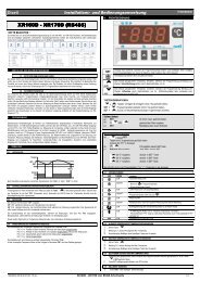
dIXELdIXEL Installing and Operating Instructions rel.2.0.0 - cod. 1592017000auxiliary: SPST relay 20(8) A, 250VacOther output :Alarm buzzer (Standard)Direct RS485 (optional)Serial output : TTL standardCommunication protocol: Modbus - RTUData storing: on the non-volatile memory (EEPROM).Internal clock back-up: 24 hoursKind of action: 1B; Pollution grade: normal; Software class: A.Operating temperature: 0÷60 °C.Storage temperature: -25÷60 °C.Relative humidity: 20÷85% (no condensing)Measuring and regulation range: NTC probe: -40÷110°C (-58÷230°F)Resolution: 0,1 °C or 1°C or 1 °F (selectable).Accuracy (ambient temp. 25°C): ±0,5 °C ±1 digit15. CONNECTIONS15.1 <strong>XLR130</strong>15.1.1 FREE VOLTAGE CONTACTS35 36RS 485optional20A 250V16FLA(96LRA)20A 250V16FLA(96LRA)16A250V~8A250V~1 2 3 4 5 6 7 8 9 10 1112 1314 151617 1819 2021 2223 2425 262728 2930 3132 3334NCNCompLightAlarm15.1.2 DIRECT LOAD CONNECTIONS15.2 <strong>XLR170</strong>15.2.1 FREE VOLTAGE CONTACTS35 36RS 485optional20A 250V16FLA(96LRA)20A 250V16FLA(96LRA)16A250V~16A 8A250V~ 250V~8A250V~1 2 3 4 5 6 7 8 9 10 1112 1314 151617 1819 2021 2223 2425 262728 2930 3132 3334NCNCLine NComp Def. Light Fan Alarm1592017000 XLR 130-170 GB r2.0 08.09.2006.doc XL130 - <strong>XLR170</strong> 16/19
dIXELdIXEL Installing and Operating Instructions rel.2.0.0 - cod. 159201700015.2.2 DIRECT LOAD CONNECTIONS16. DEFAULT SETTING VALUESLabel Name Range <strong>XLR130</strong> <strong>XLR170</strong> LevelREGULATIONSet Set point LS÷US 3.0 -5.0 ---Hy Differential 0,1÷25,5 °C / 1÷45°F 2.0 2.0 Pr1LS Minimum set point -50,0°C÷SET / -58°F÷SET -10.0 -30,0 Pr2US Maximum set point SET ÷ 110°C / SET ÷ 230°F 20.0 20.0 Pr2OdS Outputs activation delay at start up 0÷255 min. 0 0 Pr2cco Compressor configuration SE; AL SE SE Pr2AC Anti-short cycle delay 0÷30 min. 1 1 Pr1Ac1 Second compressor start up delay 0÷255 sec. 0 0 Pr2CCt Compressor ON time during fast freezing 0 ÷ 23h 50 min. 0.0 0.0 Pr2COn Compressor ON time with faulty probe 0÷255 min. 15 15 Pr2COF Compressor OFF time with faulty probe 0÷255 min. 30 30 Pr2CH Kind of action CL; Ht cL - - - Pr2DISPLAYCF Temperature measurement unit °C ÷ °F °C °C Pr2rES Resolution (integer/decimal point) in ÷ de dE dE Pr1Lod Local display P1 ÷ 1r2 P1 P1 Pr2DEFROSTtdF Defrost type rE, rT, in - - - rE Pr2EdF Defrost mode rtc, In, Sd in in Pr2SdF Set point for SMART DEFROST -30 ÷ +30°C / -22÷+86°F 0 0 Pr2dtE Defrost termination temperature (1°Evaporator) -50,0÷110°C /-58÷230°F 8.0 8.0 Pr2dtS Defrost termination temperature (2°Evaporator) -50,0÷110°C / -58÷230°F - - - 8.0 Pr2IdF Interval between defrost cycles 1÷120h 8 8 Pr1MdF (Maximum) length for 1° defrost 0÷255 min. 20 20 Pr1MdS Maximum) length for 2° defrost. 0÷255 min. - 0 Pr2dFd Displaying during defrost rt, it, SEt, dEF, dEG it it Pr2dAd MAX display delay after defrost 0÷255 min. 30 30 Pr2dSd Start defrost delay 0÷99 min. - - - 0 Pr2Fdt Draining time 0÷60 min. - - - 0 Pr2dPO First defrost after start up n ÷ y n n Pr2dAF Defrost delay after fast freezing 0 ÷ 23h 50 min. 2 2.0 Pr2dFP End defrost probe for first evaporator nP; P1, P2, P3 - - - P2 Pr2dSP End defrost probe for second evaporator nP; P1, P2, P3 - - - nP Pr2FANSFnC Fans operating mode C-n, C-y, O-n, O-y O-n O-n Pr2Fnd Fans delay after defrost 0÷255 min. 10 10 Pr2FSt Fans stop temperature -50,0÷110°C / -58÷230°F 2.0 2.0 Pr2FAP Fan probe selection nP; P1, P2, P3 nP P2 Pr2ALARMSALC Temperature alarms configuration rE÷Ab rE rE Pr2ALU MAXIMUM temperature alarm -50,0÷110°C/-58÷230°F 10.0 10.0 Pr1ALL minimum temperature alarm -50,0÷110°C/ -58÷230°F 10.0 10.0 Pr11592017000 XLR 130-170 GB r2.0 08.09.2006.doc XL130 - <strong>XLR170</strong> 17/19
dIXELdIXEL Installing and Operating Instructions rel.2.0.0 - cod. 1592017000Label Name Range <strong>XLR130</strong> <strong>XLR170</strong> LevelAFH Temperature alarm and fan differential 0,1÷25,5 °C/ 1÷45°F 2.0 2.0 Pr2ALd Temperature alarm delay 0÷255 min. 15 15 Pr2dAO Delay of temperature alarm at start up 0 ÷ 23h 50 min. 1.3 1.3 Pr2EdA Alarm delay at the end of defrost 0÷255 min. 30 30 Pr2dot Delay of temperature alarm after closing the door 0÷255 min. 15 15 Pr2dOA Open door alarm delay 0÷254 min.,nu 15 15 Pr2rrd Regulation restart after door open alarm y ÷ n y y Pr2tBA Alarm relay silencing y ÷ n y y Pr2nPS Pressure switch activation number 0÷15 0 0 Pr2ANALOGUE INPUTSOt Thermostat probe calibration -12,0÷12,0°C / -21÷21°F 0 0.0 Pr1OE Evaporator probe calibration -12,0÷12,0°C / -21÷21°F - - - 0.0 Pr2O3 Auxiliary probe calibration -12,0÷12,0°C / -21÷21°F 0 0.0 Pr2P2P Evaporator probe presence n ÷ y - - - y Pr2P3P Auxiliary probe presence n ÷ y n n Pr2Pbr Regulation probe selection P1, P2, P3, 1r2 P1 P1 Pr2HES Temperature increase during the Energy Saving cycle -30÷30°C / -54÷54°F 0 0 Pr2DIGITAL INPUTSOdc Open door control no, Fan, CPr, F_C FAn FAn Pr2I1P Door switch polarity CL÷OP cL cL Pr2I2P Configurable digital input polarity CL÷OP cL cL Pr2i2F Digital input configuration EAL, bAL, PAL,EAL EAL Pr2dFr, AUS, ES, OnFdId Digital input alarm delay 0÷255 min. 5 5 Pr2oA1 Auxiliary relay configuration dEF / ALr / FAn / LiG / AUS / onF / dF2 / cP2 AUS AUS Pr2ACH Kind of action for auxiliary relay CL; Ht cL cL Pr2SAA Set Point for auxiliary relay -50,0÷110°C / -58÷230°F 0.0 0.0 Pr2ArP Probe selection for auxiliary relay nP / P1 / P2 / P3 nP nP Pr2oAP Alarm relay polarity oP; cL cL cL Pr2TIME AND WEEKLY HOLIDAYSHur Current hour 0 ÷ 23 0 Pr2 Pr2Min Current minute 0 ÷ 59 0 Pr2 Pr2dAY Current day Sun ÷ SAt Sun Pr2 Pr2Hd1 First weekly holiday Sun÷ SAt – nu nu Pr2 Pr2Hd2 Second weekly holiday Sun÷ SAt – nu nu Pr2 Pr2Hd3 Third weekly holiday Sun÷ SAt – nu nu Pr2 Pr2ENERGY SAVING TIMESILE Energy Saving cycle start during workdays 0 ÷ 23h 50 min. 0 Pr2 Pr2dLE Energy Saving cycle length during workdays 0 ÷ 24h 00 min. 0 Pr2 Pr2ISE Energy Saving cycle start on holidays 0 ÷ 23h 50 min. 0 Pr2 Pr2dSE Energy Saving cycle length on holidays 0 ÷ 24h 00 min. 0 Pr2 Pr2HES Temperature increase during the Energy Saving cycle -30÷30°C / -54÷54°F 0 Pr2 Pr2DEFROST TIMESLd1 1 st workdays defrost start 0 ÷ 23h 50 min. - nu 6.0 6.0 Pr1Ld2 2 nd workdays defrost start 0 ÷ 23h 50 min. - nu 13.0 13.0 Pr1Ld3 3 rd workdays defrost start 0 ÷ 23h 50 min. - nu 21.0 21.0 Pr1Ld4 4 th workdays defrost start 0 ÷ 23h 50 min. - nu 0.0 0.0 Pr1Ld5 5 th workdays defrost start 0 ÷ 23h 50 min. - nu 0.0 0.0 Pr1Ld6 6 th workdays defrost start 0 ÷ 23h 50 min. - nu 0.0 0.0 Pr1Ld7 7 th workdays defrost start 0 ÷ 23h 50 min. - nu 0.0 0.0 Pr1Ld8 8 th workdays defrost start 0 ÷ 23h 50 min. - nu 0.0 0.0 Pr1Sd1 1 st holiday defrost start 0 ÷ 23h 50 min. - nu 6.0 6.0 Pr1Sd2 2 nd holiday defrost start 0 ÷ 23h 50 min. - nu 13.0 13.0 Pr1Sd3 3 rd holiday defrost start 0 ÷ 23h 50 min. - nu 21.0 21.0 Pr1Sd4 4 th holiday defrost start 0 ÷ 23h 50 min. - nu 0.0 0.0 Pr1Sd5 5 th holiday defrost start 0 ÷ 23h 50 min. - nu 0.0 0.0 Pr1Sd6 6 th holiday defrost start 0 ÷ 23h 50 min. - nu 0.0 0.0 Pr11592017000 XLR 130-170 GB r2.0 08.09.2006.doc XL130 - <strong>XLR170</strong> 18/19
dIXELdIXEL Installing and Operating Instructions rel.2.0.0 - cod. 1592017000Label Name Range <strong>XLR130</strong> <strong>XLR170</strong> LevelSd7 7 th holiday defrost start 0 ÷ 23h 50 min. - nu 0.0 0.0 Pr1Sd8 8 th holiday defrost start 0 ÷ 23h 50 min. - nu 0.0 0.0 Pr1OTHERAdr Serial address 0÷247 1 1 Pr2Pbc Kind of probe selection Pbc, ntc ntc ntc Pr2rEL Software release - - - 4.5 4.5 Pr1Ptb Map code - - - - - - - - - Pr1dP1 First probe display --- - - - - - - Pr1dP2 Second probe display --- - - - - - - Pr1dP3 Third probe display --- - - - - - - Pr1Pr2 Access parameter list - - - - - - - - - Pr1Dixell S.p.A. Via dell’Industria, 27 - 32010 Z.I Pieve d’Alpago (BL) ITALYtel. +39 – 0437 - 98 33 – fax +39 - 0437 - 98 93 13E-mail: dixell@dixell.com - http://www.dixell.com1592017000 XLR 130-170 GB r2.0 08.09.2006.doc XL130 - <strong>XLR170</strong> 19/19