XLR130 â XLR170 - Copyright Arctica Oy
XLR130 â XLR170 - Copyright Arctica Oy
XLR130 â XLR170 - Copyright Arctica Oy
- No tags were found...
Create successful ePaper yourself
Turn your PDF publications into a flip-book with our unique Google optimized e-Paper software.
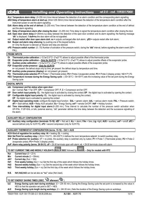
dIXELdIXEL Installing and Operating Instructions rel.2.0.0 - cod. 1592017000ALd Temperature alarm delay: (0÷255 min) time interval between the detection of an alarm condition and the corresponding alarm signalling.dAO Delay of temperature alarm at start-up: (0min÷23h 50min) time interval between the detection of the temperature alarm condition after theinstrument power on and the alarm signalling.EdA Alarm delay at the end of defrost: (0÷255 min) Time interval between the detection of the temperature alarm condition at the end of defrostand the alarm signalling.dot Delay of temperature alarm after closing the door : (0÷255 min) Time delay to signal the temperature alarm condition after closing the door.doA Open door alarm delay:(0÷254min,nu) delay between the detection of the open door condition and its alarm signalling: the flashing message“dA” is displayed. If doA=nu the door alarm will be not signalled.rrd Output restart after door open alarm doA: no = outputs unchanged after doA alarm; yES = outputs restart after doA alarm;tbA Buzzer and alarm relay silencing: by pushing one of the keypad buttons.n= Only the Buzzer is silenced; y= Buzzer and relay are silenced.nPS Pressure switch number: (0 ÷15) Number of activation of the pressure switch, during the “did” interval, before signalling the alarm event (I2F=PAL).PROBE INPUTSOt Thermostat probe calibration: (-12.0÷12.0°C/ -21÷21°F) allows to adjust possible offset of the thermostat probe.OE Evaporator probe calibration – Only for <strong>XLR170</strong>: (-12.0÷12.0°C/ -21÷21°F) allows to adjust possible offsets of the evaporator probe.O3 Auxiliary probe calibration: (-12.0÷12.0°C/ -21÷21°F) allows to adjust possible offsets of the evaporator probe.P2P Evaporator probe presence - Only for <strong>XLR170</strong>:n= not present: the defrost stops only by time; y= present: the defrost stops by temperature and time.P3P Auxiliary probe presence (display): n= not present; y= present.Pbr Thermostat probe selection P1 = Probe 1 (Thermostat probe); P2 = Probe 2 (evaporator probe); P3 = Probe 3 (display probe); 1r2 = P1-P2.HES Temperature increase during the Energy Saving cycle : (-30÷30°C / -54÷54°F) sets the increasing value of the set point during the EnergySaving cycle.DIGITAL INPUTSodc Compressor and fan status when open door:no = normal; Fan = Fan OFF; CPr = Compressor OFF; F_C = Compressor and fan OFF.I1P Door switch input polarity: CL : the digital input is activated by closing the contact; OP : the digital input is activated by opening the contact.I2P Configurable digital input polarity: CL : the digital input is activated by closing the contact;OP : the digital input is activated by opening the contactI2F Digital input operating mode: configure the digital input function: EAL = generic alarm; bAL = serious alarm mode; PAL = Pressure switch;dFr = Start defrost; AUS = Relay AUX actuation; Es = Energy Saving; onF = remote On/OFF; HdF = Holiday function.did Time interval/delay for digital input alarm:(0÷255 min.) Time interval to calculate the number of the pressure switch activation whenI2F=PAL. If I2F=EAL or bAL (external alarms), “did” parameter defines the time delay between the detection and the successive signalling ofthe alarm.AUXILIARY RELAY CONFIGURATIONoA1 Auxiliary relay configuration (terminals 15-16): dEF = Not set it; ALr = alarm; FAn = fans; Lig =light; AUS = auxiliary; onF = on/off; dF2 =second defrost (only for <strong>XLR170</strong>), cP2 = second compressor (only for <strong>XLR170</strong>).AUXILIARY THERMOSTAT CONFIGURATION (terms. 15-16) – OA1 = AUSACH Kind of regulation for auxiliary relay: Ht = heating; CL = coolingSAA Set Point for auxiliary relay: (-50,0÷110,0°C; -58÷230°F) it defines the room temperature setpoint to switch auxiliary relay.ArP Probe selection for auxiliary: nP = no probe, the auxiliary relay is switched only by button; P1 = Probe 1 (Thermostat probe); P2 = Probe 2(evaporator probe); P3 = Probe 3 (display probe).AoP Alarm relay polarity (terms. 29-30-31): oP = 29-30 terminals open with alarm; cL = 29-30 terminals close with alarmTO SET CURRENT TIME AND WEEKLY HOLIDAYS ( 3SEC followed by ) – Only for models with RTCHur Current hour (0 ÷ 23 h)Min Current minute (0 ÷ 59min)dAY Current day (Sun ÷ SAt)Hd1 First weekly holiday (Sun ÷ nu) Set the first day of the week which follows the holiday times.Hd2 Second weekly holiday (Sun ÷ nu) Set the second day of the week which follows the holiday times.Hd3 Third weekly holiday (Sun ÷ nu) Set the third day of the week which follows the holiday times.N.B.Hd1,Hd2,Hd3 can be set also as “nu” value (Not Used).TO SET ENERGY SAVING TIMES (3SEC. afterward )ILE Energy Saving cycle start during workdays: (0 ÷ 23h 50 min.) During the Energy Saving cycle the set point is increased by the value inHES so that the operation set point is SET + HES.dLE Energy Saving cycle length during workdays: (0 ÷ 24h 00 min.) Sets the duration of the Energy Saving cycle on workdays.1592017000 XLR 130-170 GB r2.0 08.09.2006.doc XL130 - <strong>XLR170</strong> 10/19


