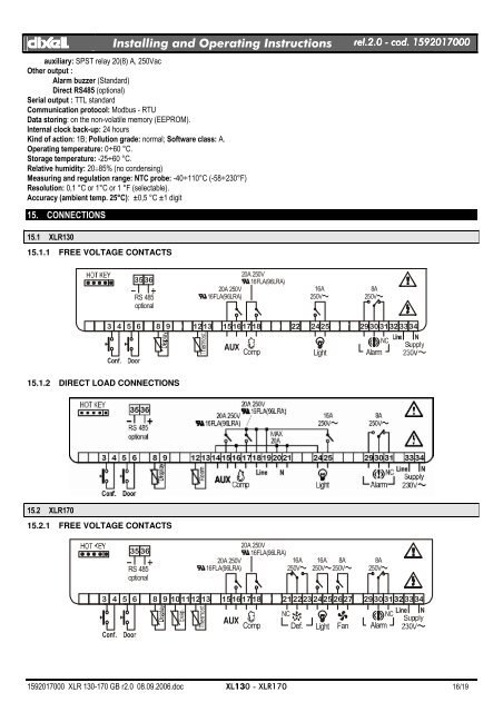
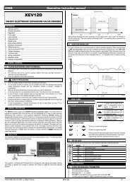
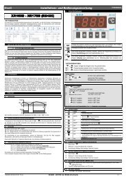
dIXELdIXEL Installing and Operating Instructions rel.2.0.0 - cod. 1592017000auxiliary: SPST relay 20(8) A, 250VacOther output :Alarm buzzer (Standard)Direct RS485 (optional)Serial output : TTL standardCommunication protocol: Modbus - RTUData storing: on the non-volatile memory (EEPROM).Internal clock back-up: 24 hoursKind of action: 1B; Pollution grade: normal; Software class: A.Operating temperature: 0÷60 °C.Storage temperature: -25÷60 °C.Relative humidity: 20÷85% (no condensing)Measuring and regulation range: NTC probe: -40÷110°C (-58÷230°F)Resolution: 0,1 °C or 1°C or 1 °F (selectable).Accuracy (ambient temp. 25°C): ±0,5 °C ±1 digit15. CONNECTIONS15.1 <strong>XLR130</strong>15.1.1 FREE VOLTAGE CONTACTS35 36RS 485optional20A 250V16FLA(96LRA)20A 250V16FLA(96LRA)16A250V~8A250V~1 2 3 4 5 6 7 8 9 10 1112 1314 151617 1819 2021 2223 2425 262728 2930 3132 3334NCNCompLightAlarm15.1.2 DIRECT LOAD CONNECTIONS15.2 <strong>XLR170</strong>15.2.1 FREE VOLTAGE CONTACTS35 36RS 485optional20A 250V16FLA(96LRA)20A 250V16FLA(96LRA)16A250V~16A 8A250V~ 250V~8A250V~1 2 3 4 5 6 7 8 9 10 1112 1314 151617 1819 2021 2223 2425 262728 2930 3132 3334NCNCLine NComp Def. Light Fan Alarm1592017000 XLR 130-170 GB r2.0 08.09.2006.doc XL130 - <strong>XLR170</strong> 16/19
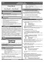
dIXELdIXEL Installing and Operating Instructions rel.2.0.0 - cod. 159201700015.2.2 DIRECT LOAD CONNECTIONS16. DEFAULT SETTING VALUESLabel Name Range <strong>XLR130</strong> <strong>XLR170</strong> LevelREGULATIONSet Set point LS÷US 3.0 -5.0 ---Hy Differential 0,1÷25,5 °C / 1÷45°F 2.0 2.0 Pr1LS Minimum set point -50,0°C÷SET / -58°F÷SET -10.0 -30,0 Pr2US Maximum set point SET ÷ 110°C / SET ÷ 230°F 20.0 20.0 Pr2OdS Outputs activation delay at start up 0÷255 min. 0 0 Pr2cco Compressor configuration SE; AL SE SE Pr2AC Anti-short cycle delay 0÷30 min. 1 1 Pr1Ac1 Second compressor start up delay 0÷255 sec. 0 0 Pr2CCt Compressor ON time during fast freezing 0 ÷ 23h 50 min. 0.0 0.0 Pr2COn Compressor ON time with faulty probe 0÷255 min. 15 15 Pr2COF Compressor OFF time with faulty probe 0÷255 min. 30 30 Pr2CH Kind of action CL; Ht cL - - - Pr2DISPLAYCF Temperature measurement unit °C ÷ °F °C °C Pr2rES Resolution (integer/decimal point) in ÷ de dE dE Pr1Lod Local display P1 ÷ 1r2 P1 P1 Pr2DEFROSTtdF Defrost type rE, rT, in - - - rE Pr2EdF Defrost mode rtc, In, Sd in in Pr2SdF Set point for SMART DEFROST -30 ÷ +30°C / -22÷+86°F 0 0 Pr2dtE Defrost termination temperature (1°Evaporator) -50,0÷110°C /-58÷230°F 8.0 8.0 Pr2dtS Defrost termination temperature (2°Evaporator) -50,0÷110°C / -58÷230°F - - - 8.0 Pr2IdF Interval between defrost cycles 1÷120h 8 8 Pr1MdF (Maximum) length for 1° defrost 0÷255 min. 20 20 Pr1MdS Maximum) length for 2° defrost. 0÷255 min. - 0 Pr2dFd Displaying during defrost rt, it, SEt, dEF, dEG it it Pr2dAd MAX display delay after defrost 0÷255 min. 30 30 Pr2dSd Start defrost delay 0÷99 min. - - - 0 Pr2Fdt Draining time 0÷60 min. - - - 0 Pr2dPO First defrost after start up n ÷ y n n Pr2dAF Defrost delay after fast freezing 0 ÷ 23h 50 min. 2 2.0 Pr2dFP End defrost probe for first evaporator nP; P1, P2, P3 - - - P2 Pr2dSP End defrost probe for second evaporator nP; P1, P2, P3 - - - nP Pr2FANSFnC Fans operating mode C-n, C-y, O-n, O-y O-n O-n Pr2Fnd Fans delay after defrost 0÷255 min. 10 10 Pr2FSt Fans stop temperature -50,0÷110°C / -58÷230°F 2.0 2.0 Pr2FAP Fan probe selection nP; P1, P2, P3 nP P2 Pr2ALARMSALC Temperature alarms configuration rE÷Ab rE rE Pr2ALU MAXIMUM temperature alarm -50,0÷110°C/-58÷230°F 10.0 10.0 Pr1ALL minimum temperature alarm -50,0÷110°C/ -58÷230°F 10.0 10.0 Pr11592017000 XLR 130-170 GB r2.0 08.09.2006.doc XL130 - <strong>XLR170</strong> 17/19