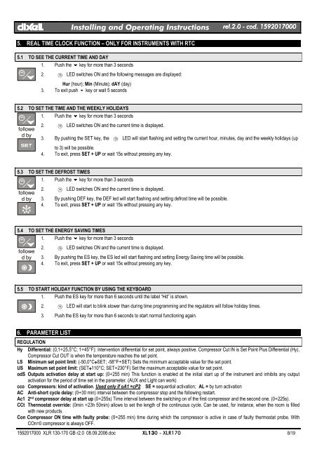
dIXELdIXEL Installing and Operating Instructions rel.2.0.0 - cod. 15920170005. REAL TIME CLOCK FUNCTION – ONLY FOR INSTRUMENTS WITH RTC5.1 TO SEE THE CURRENT TIME AND DAY1. Push the n key for more than 3 seconds2.eLED switches ON and the following messages are displayed:Hur (hour); Min (Minute); dAY (day)3. To exit push n key or wait 5 seconds5.2 TO SET THE TIME AND THE WEEKLY HOLIDAYSfollowed by1. Push the n key for more than 3 seconds2.eLED switches ON and the current time is displayed.3. By pushing the SET key, the eLED will start flashing and setting the current hour, minutes, day and the weekly holidays (upto 3) will be possible.4. To exit, press SET + UP or wait 15s without pressing any key.5.3 TO SET THE DEFROST TIMESfollowed by1. Push the n key for more than 3 seconds2.eLED switches ON and the current time is displayed.3. By pushing DEF key, the DEF led will start flashing and setting defrost time will be possible.4. To exit, press SET + UP or wait 15s without pressing any key.5.4 TO SET THE ENERGY SAVING TIMESfollowed by1. Push the n key for more than 3 seconds2.eLED switches ON and the current time is displayed.3. By pushing the ES key, the ES led will start flashing and setting Energy Saving time will be possible.4. To exit, press SET + UP or wait 15s without pressing any key.5.5 TO START HOLIDAY FUNCTION BY USING THE KEYBOARD1. Push the ES key for more than 6 seconds until the label “Hd” is shown.2.eLED will start to blink slower than during time programming and the regulators will follow holiday times.3. Push the ES key for more than 6 seconds to start normal functioning again.6. PARAMETER LISTREGULATIONHy Differential: (0,1÷25,5°C; 1÷45°F): Intervention differential for set point, always positive. Compressor Cut IN is Set Point Plus Differential (Hy).Compressor Cut OUT is when the temperature reaches the set point.LS Minimum set point limit: (-50,0°C÷SET; -58°F÷SET) Sets the minimum acceptable value for the set point.US Maximum set point limit: (SET÷110°C; SET÷230°F) Set the maximum acceptable value for set point.odS Outputs activation delay at start up: (0÷255 min) This function is enabled at the initial start up of the instrument and inhibits any outputactivation for the period of time set in the parameter. (AUX and Light can work)cco Compressors: kind of activation. Used only if oA1 =cP2: SE = sequential activation; AL = by turn activationAC Anti-short cycle delay: (0÷30 min) interval between the compressor stop and the following restart.Ac1 2 nd compressor delay at start up (0÷255s) Time interval between the switching on of the first compressor and the second one. (0÷225s).CCt Thermostat override: (0min ÷23h 50min) allows to set the length of the continuous cycle. Can be used, for instance, when the room is filledwith new products.Con Compressor ON time with faulty probe: (0÷255 min) time during which the compressor is active in case of faulty thermostat probe. WithCOn=0 compressor is always OFF.1592017000 XLR 130-170 GB r2.0 08.09.2006.doc XL130 - <strong>XLR170</strong> 8/19
dIXELdIXEL Installing and Operating Instructions rel.2.0.0 - cod. 1592017000COF Compressor OFF time with faulty probe: (0÷255 min) time during which the compressor is off in case of faulty thermostat probe. WithCOF=0 compressor is always active.CH Type of action - Only for <strong>XLR130</strong>: CL = cooling; Ht = heating..DISPLAYCF Temperature measurement unit: °C = Celsius; °F = Fahrenheit . When the measurement unit is changed the SET point and the values of theregulation parameters have to be modifiedrES Resolution (for °C): (in = 1°C; de = 0,1°C) allows decimal point display. dE = 0,1°C; in = 1 °CLod Local display : select which probe is displayed by the instrument: P1 = Thermostat probe; P2 = Evaporator probe; P3 = auxiliary probe1r2 = difference between P1 and P2 (P1-P2)DEFROSTtdF Defrost type Only for <strong>XLR170</strong>: rE = electrical heater (Compressor OFF); rT = thermostat defrost. During the defrost time “MdF”, the heaterswitches On and OFF depending on the evaporator temperature and “dtE” value; in = hot gas (Compressor and defrost relays ON)EdF Defrost mode:rtc = Real Time Clock mode. Defrost time follows Ld1÷Ld8 parameters on workdays and Sd1÷Sd8 on holidays. Available only if the ’RTCoption is presentin = interval mode. The defrost starts when the time “Idf” is expired.Sd = Smartfrost mode. The time IdF (interval between defrosts) is increased only when the compressor is running (even non consecutively)and only if the evaporator temperature is less than the value in "SdF” (set point for SMARTFROST).SdF Set point for SMARTFROST: (-30÷30 °C/ -22÷86 °F) evaporator temperature which allows the IdF counting (interval between defrosts) inSMARTFROST mode.dtE Defrost termination temperature Only for <strong>XLR170</strong>: (-50,0÷110,0°C; -58÷230°F) (Enabled only when the evaporator probe is present) setsthe temperature measured by the evaporator probe which causes the end of defrost.dtS Defrost termination temperature 2 nd evaporator – Only for <strong>XLR170</strong> if oA1=dF2 : (-50,0÷110,0°C; -58÷230°F) sets the temperaturemeasured by the 2 nd evaporator probe which causes the end of defrost.IdF Interval between defrosts: (1÷120h) Determines the time interval between the beginning of two defrost cycles.MdF (Maximum) duration of defrost: (0÷255 min) When P2P = n, no evaporator probe, it sets the defrost duration, when P2P = y, defrost endbased on temperature, it sets the maximum length for defrost.MdS (Maximum) duration of defrost for 2 nd evaporator – Only for <strong>XLR170</strong> if oA1=dF2: (0÷255 min) It sets the maximum duration of the defrostfor 2 nd evaporator.dFd Display during defrost: rt = real temperature; it = temperature at the defrost start; Set = set point; dEF = “dEF” label; dEG = “dEG” label;dAd Defrost display time out: (0÷255 min) Sets the maximum time between the end of defrost and the restarting of the real room temperaturedisplay.dSd Start defrost delay - Only for <strong>XLR170</strong>: ( 0÷99min) This is useful when different defrost start times are necessary to avoid overloading theplant.Fdt Drain down time: (0÷60 min.) time interval between reaching defrost termination temperature and the restoring of the control’s normaloperation. This time allows the evaporator to eliminate water drops that might have formed due to defrost.dPO First defrost after start-up:y = Immediately; n = after the IdF timedAF Defrost delay after fast freezing: (0min÷23h 50min) after a Fast Freezing cycle, the first defrost will be delayed for this time.dFP End defrost probe for first evaporator selection – Only for <strong>XLR170</strong>: nP = no probe, defrost by time. Duration set by MdF parameter; P1 =Probe 1 (thermostat probe); P2 = Probe 2 (evaporator probe); P3 = Probe 3 (display probe).dSP End defrost probe for second evaporator selection – Only for <strong>XLR170</strong>: nP = no probe, defrost by time. Duration set by MdS parameter; P1= Probe 1 (thermostat probe); P2 = Probe 2 (evaporator probe); P3 = Probe 3 (display probe).FANSFnC Fan operating mode: C-n = running with the compressor, OFF during the defrost;C-y = running with the compressor, ON during the defrost;O-n = continuous mode, OFF during the defrost;O-y = continuous mode, ON during the defrost;Fnd Fan delay after defrost: (0÷255 min) The time interval between the defrost end and evaporator fans start.FSt Fan stop temperature: (-50÷110°C; -58÷230°F) setting of temperature, detected by evaporator probe, above which the fan is always OFF.dSP Fan probe selection: nP = no probe, fans act according to the Fnc parameter, without temperature control set in FSt parameter; P1 = Probe 1(Thermostat probe); P2 = Probe 2 (evaporator probe); P3 = Probe 3 (display probe).ALARMSALC Temperature alarm configuration: rE = High and Low alarms related to Set Point;Ab = High and low alarms related to the absolute temperature.ALU High temperature alarm setting: ( ALC= rE, 0 ÷ 50°C or 90°F; ALC= Ab, ALL ÷ 110°C or 230°F)when this temperature is reached and after the ALd delay time the HA alarm is enabled.ALL Low temperature alarm setting: ( ALC = rE , 0 ÷ 50 °C or 90°F; ALC = Ab , - 50°C or -58°F ÷ ALU)when this temperature is reached and after the ALd delay time, the LA alarm is enabled,.AFH Temperature alarm and fan differential: (0,1÷25,5°C; 1÷45°F) Intervention differential for temperature alarm set point and fan regulation setpoint, always positive.1592017000 XLR 130-170 GB r2.0 08.09.2006.doc XL130 - <strong>XLR170</strong> 9/19