<strong>SHURflo</strong> Operating Instructions, Performance,Specifications and Parts Manual<strong>SHURflo</strong> 316 Stainless Steel RotaryPedestal External Gear PumpsViton Models GPSV2, GPSV4 and GPSV6Teflon ® Models GPST2, GPST4 and GPST6Operation (Continued)seal chamber and will ensure liquidcirculation to the mechanical seal.2. Gear pumps are built to very closetolerances and this tolerance mustnot be altered. The liquids must,therefore, be free of all abrasives.Sand, silt, wettable powders, etc.must be avoided.3. When pumping a more viscous(beyond 500 SSU) liquid; a slowerspeed, a larger pipe size pump,and possibly a larger motor shouldbe selected.NOTE: See performance chart for Max.Torque.4. Recheck motor and pump rotation.Pump rotation is by-directional(See Figure 1).PRESSURE RELIEF VALVE5. Standard models do not include apressure relief valve. If discharge isgoing to be shut off, an externalpressure relief valve should beinstalled.GEAR PUMP GASKET ADJUSTMENTFOR TEMPERATURE (see Appendix 1)6. For operation in fluid temperaturesabove 120° F, stainless steel pumpmodels must have the gasket thicknessadjusted. Use Appendix 1 toidentify pump, temperature andgasket recommendations for adjustingthe cover clearance prior tooperation in elevated temperaturesor viscosities above 500 SSU.Failure to adjust pumpcover clearances foroperating temperatures above 120° F. willresult in severe pump and/or motor damage.NOTE: When pumping fluids of highviscosity (>500 ssu), the required torqueand HP can be reduced by adding agasket for increased gear clearance.DRIVE CONNECTIONSNOTE: Pedestal Gear Pumps will operateequally well in either direction (SeeFigure 1). When looking at the pumpdrive shaft end and rotating the shaftclockwise, the discharge port is on theright-hand side. When turning counterclockwise,the discharge port is on theleft-hand side.DIRECT COUPLING DRIVESNever use a rigid coupling between thepump and the motor. Some degree offlexibility must be allowed at thecoupling to avoid excessive side loadingof the motor and pump bearings. Anyflexible coupling rated for the horsepowerload and speed is satisfactory.Care should be taken that the pumpand motor shaft are in alignment.Misalignment will cause unnecessaryloads on the pump and motor bearings.NOTE: Unit is not recommended fordirect drive by engine (gasoline ordiesel). If engine drive is desired, a “V”-belt arrangement is recommended toreduce torque pulsations on the pump.PULLEY DRIVEIn some cases, a reduction in pumpspeed is essential. This may be accomplishedthrough a belt and pulley drive.Bear in mind, however, that belt tensionadds a side thrust to the pump driveshaft which results in extra bearingloading and wear with resulting shortenedpump life. Adjust belt tension tobelt manufacturers’ recommendations.7. For pulley-driven pumps, a single1/2 (A or 4L section) “V” belt issatisfactory for drive sizes andspeeds up to 1 HP, 3450 RPM. Forlarger drive sizes, double “V” beltsare recommended. Maximum pumpRPM is 1725.8. Install safety guards, shield, etc.,around all moving parts.Failure to installproper safety guards,shields, etc. can result in property damageand/or personal injury. Follow all electricaland safety codes, as well as United StatesNational Electrical Code (NEC) andOccupational Safety and Health Act (OSHA).9. When using an electric motor, makenecessary electrical connections forthe voltage outlet supply anddouble-check all connections.Check power connections for propervoltage. (Refer to wiring diagramon motor nameplate or inside theterminal box for the properconnections.) See General SafetyInformation.IMPORTANT: Electrical circuit must beproperly fused.MECHANICAL SEAL FLUSHINSTALLATION OPTIONS10. These stainless steel pumps areequipped with mechanical seals andhave been designed with flush portsbecause mechanical seals requirecooling lubrication for long life.a. For fluids with viscosities less than2000 SSU, a flush is not necessary,but the seal cavity must be prefilledwith either the operatingfluid or a neutral fluid. This is toensure seal cooling and lubricationduring start-up (See Figure 3).Failure to provideinitial seal prime canresult in the mechanical seal overheatingwith resulting repair costs.b. For high viscosity fluids, a flushwill be necessary. The seal mustbe cooled and lubricated by afluid. In the case of high viscosityfluids, due to the precision clearancesbetween the gear teeth andthe stainless steel body, highlyviscous fluids will not be able toadequately relieve the air in theseal cavity on start-up. The dryrunning of a mechanical sealForm L-<strong>4088</strong> (12/09)8
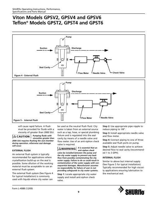
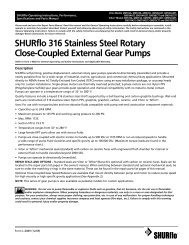
<strong>SHURflo</strong> Operating Instructions, Performance,Specifications and Parts ManualViton Models GPSV2, GPSV4 and GPSV6Teflon ® Models GPST2, GPST4 and GPST6PumpSuctionDischargeSeal CavityFigure 4 - External FlushFlow MeterNeedle ValveCheck ValvePumpSuctionDischargeSeal CavityFigure 5 - Internal Flushwill cause rapid failure. A flushmust be provided for fluids with aviscosity of greater than 2000 SSU.Pumping fluids withviscosities greater than2000 SSU requires flushing the seal chamberduring operation, otherwise seal damagewill occur.EXTERNAL FLUSHAn external flush system is typicallyrecommended for applications wherecrystallization build-up on the seal ispossible. Some dilution of the workingmaterial must be acceptable to use anexternal flush system.The external flush system (See Figure 4for typical installation) is commonlyused with liquids where city water canFlow Meterbe used as the neutral flush fluid. Citywater is taken from an external sourcesuch as a tap, hose, or special plumbingfixture and is regulated into the sealcavity by means of a needle valve andflow meter. Use of an anti-siphon checkvalve is required.It is essential that ananti-siphon checkvalve be installed between the pump andthe city water supply to prevent any backflow from possibly contaminating the citywater supply. Failure to do so could result incontamination of the water supply with consequentialdamages. Manufacturer assumesno responsibility for failure of user in notproviding safeguards to city water systems.Step 1: Locate appropriate city watersupply and install anti-siphon checkvalve.Needle ValveStep 2: Use appropriate pipe nipple toreduce piping to 1/8”.Step 3: Install appropriate needle valveand flow meter.Step 4: Connect piping to one of threeavailable seal flush ports on pump.Step 5: Adjust needle valve to achievedesired flow to seal cavity (recommended1 to 3 GPH).INTERNAL FLUSHSimilar to above but internal supply(See Figure 5 for typical installation).Typically recommended for high viscosityapplications ensuring lubrication tothe mechanical seal.Form L-<strong>4088</strong> (12/09)9