Wavetronix - Advanced Traffic Products
Wavetronix - Advanced Traffic Products
Wavetronix - Advanced Traffic Products
- No tags were found...

Create successful ePaper yourself
Turn your PDF publications into a flip-book with our unique Google optimized e-Paper software.
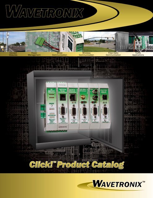
<strong>Wavetronix</strong>ContactClosuresPowerManagementWiredCommunicationWirelessCommunicationFiber-OpticCommunication<strong>Traffic</strong>ApplicationsClick! Product CatalogwAVETRONIX TM
<strong>Wavetronix</strong>380 South Technology Ct.Lindon, UT 84042 USAPhone: (801) 764-0277Fax: (801) 764-0208Web: www.wavetronix.comEmail: sales@wavetronix.comContact <strong>Wavetronix</strong>for more Click!product information.OnlineVisit our website at: www.wavetronix.comClick!, Simple Connectivity, Click! Supervisor,SmartSensor and all associated logos aretrademarks of <strong>Wavetronix</strong> LLC.All other product or brand names as they appearare trademarks or registered trademarks of theirrespective holders.SmartSensor is protected by U.S. Patent Nos.6,556,916 and 6,693,557. Other U.S. andinternational patents pending.The Company shall not be liable for any errorscontained herein or for any damages arising outof or related to this document or the informationcontained therein, even if the Company has beenadvised of the possibility of such damages.This document is intended for informational andinstructional purposes only. The Company reservesthe right to make changes in the specificationsand other information contained in this documentwithout prior notification.© 2007 <strong>Wavetronix</strong> LLC.All rights reserved.EmailEmail us at: sales@wavetronix.comTelephoneCall <strong>Wavetronix</strong> at: 1-801-764-0277<strong>Wavetronix</strong> DealersContact us and we’ll set up a meeting withyou and an authorized <strong>Wavetronix</strong> dealer todeliver Click! product information in person.DEMOClick! product demonstrations are availableupon request. Call or email today!Click! Warranty<strong>Wavetronix</strong> offers a warranty on each Click! product for a period of one (1) year following the sale andshipment of each device. This warranty ensures that each Click! device will be free from defects; if any Click!device fails under normal use, <strong>Wavetronix</strong> will repair or replace it at no charge. This warranty applies onlyto devices manufactured by <strong>Wavetronix</strong>, and does not apply to equipment that has been altered or repairedwithout <strong>Wavetronix</strong>’ permission, or to equipment that has not been properly installed. To find out more aboutthis warranty, contact <strong>Wavetronix</strong> or an authorized <strong>Wavetronix</strong> dealer.
Contents6810141822303234Click! ValueSimple ConnectivityClick! TechnologyClick! and Go DesignClick! 100 SeriesContact ClosuresClick! 200 SeriesPower ManagmentClick! 300 SeriesWired CommunicationClick! 400 SeriesWireless CommunicationClick! 700 SeriesFiber-Optic CommunicationClick! 800 Series<strong>Traffic</strong> ApplicationsProduct Selection GuidePick your Click!
Click!ProductLineContact ClosuresClick! 100 16-Output ModuleClick! 172 2-Channel Rack CardClick! 174 4-Channel Rack CardPower ManagementClick! 200 Surge ProtectorClick! 201 1-Amp Power SupplyClick! 202 2-Amp Power SupplyWired CommunicationClick! 301 Serial to EthernetClick! 304 RS-232 to RS-485Click! 305 Serial to USBWireless CommunicationClick! 400 900 MHz RadioClick! 401 802.11b RadioClick! 402 GPRS RadioClick! 403 Bluetooth® RadioFiber-Optic CommunicationClick! 700 Serial to Fiber-OpticClick! 701 Serial to Fiber-Optic<strong>Traffic</strong> ApplicationsClick! 800 Alert Module
Click! ValueSimple ConnectivityThe <strong>Wavetronix</strong> Click! line’s broad range of easy-to-use, easy-to-integrate products makesit easy to connect power and communications for traffic systems.<strong>Wavetronix</strong><strong>Wavetronix</strong> Click! products are all about making the rightconnections. Click! devices are designed to connect varioustraffic components into one unified system, providing the power,communications and signaling solutions needed for effectivetraffic control and management. With a broad range of productsthat are easy to use, Click! products are built and tested toquickly integrate together and to operate under even the harshestenvironmental conditions.Broad Family of <strong>Products</strong>Click! offers a wide range of in-the-field components that supporttraffic systems and communication networks. The breadth ofthe Click! product line makes <strong>Wavetronix</strong> the one-stop source forcomponents compatible with many types of field cabinets.Available components include:• 900 MHz Radio• 802.11b (WiFi) Radio• GPRS Cellular Radio• Bluetooth Radio• Serial to Ethernet Converter• RS-232 to RS-485 Converter• Serial to Fiber Converters• Surge Suppressors• Power Supplies• Contact Closure ModulesAll components are easy-to-use and quickly integratetogether to form a complete network. While the power and surge
protection modules are specifically designed to mount easilyon a DIN rail, the Click! communication modules are availablein three form factors: DIN rail mountable modules; rack cards;and 170 Controller modem cards. This way, for most in-fieldcommunications, <strong>Wavetronix</strong> can provide the communicationinterface required for any type of traffic cabinet.Easy IntegrationEach product in the Click! line has been designed and tested towork together, reducing the amount of time required to integratedevices from multiple vendors as well as the time needed to solvethe problems that can arise from integrating dissimilar devices.Two unique features help make Click! easy to integrate: first,Click! modules share a common power and communication bus,so each module literally “clicks” together for instant integration;second, Click! modules mount to a DIN rail, so the physical integrationof all required modules into a single cabinet is simple,clean and easy to expand in a well-defined way without clutteringup the cabinet with different-sized boxes and power supplies.The photograph below illustrates how easy it is to integrateClick! devices into a traffic monitoring cabinet. In this example,the cabinet is a fiber optic, AC-powered SmartSensor stationwith surge protection, power and communication modules allcontained within a 12 inch by 14 inch by 8 inch fiberglass cabinet.Notice how the shared modular architecture and the simple wiringdesign of the Click! devices eliminates the mess of jumbled boxesand tangled wires common in traffic cabinets.In addition to being clean and compact, the DIN rail mountingand hot-swappability of the Click! modules make it easy to upgradeor customize the cabinet without disrupting any other devices inthe network. For example, a technician could convert this cabinetfrom fiber optic to wireless communications by simply removingthe Click! 700 Serial to Fiber converter and replacing it with aClick! 400 900 MHz radio. The exchange can be made withoutrewiring cables or drilling new holes; Click!’s “click and go”design does the job without causing unnecessary interruptions tothe rest of the network.Reliable SolutionsThe Click! family’s common hardware and software platformsreduce the complexities of designing, building and maintaininga traffic monitoring system, while providing the power and communicationsolutions needed for effective traffic management.Contact <strong>Wavetronix</strong> to learn more about the value Click! productscan add to your system. See the inside front cover for details.What’s in YOUR Cabinet?DIN Rail MountableEasy toCustomizeand ExpandHot SwappableModulesClean & Compact DesignClick! modules are available in rackcard configurations.
Click! TechnologyClick! and Go DesignModular architecture and intelligent configuration tools make the <strong>Wavetronix</strong> Click! productsthe easiest, most reliable way to build a traffic system.I0I00I00I00I00I00I0I00I00I00I00III00I0I00I0I0I0I0I00I0I0I0III0I000I0I000I0I0T-busConnectorT-busConnector<strong>Wavetronix</strong>The simple connectivity of the <strong>Wavetronix</strong> Click! productfamily makes it easy to design and implement traffic systems.From power and surge protection devices to in-the-field datacommunication solutions, Click! products have been engineeredto simplify system design and standardize performance.The technology that supports Click!’s simple connectivity isunique in the traffic equipment industry. First, each communicationproduct shares a common communication interface for improvedintegration of multiple devices. Second, each Click! productis extensively tested throughout the design and manufacturingprocess to ensure that each device operates properly in eventhe harshest roadside conditions. Third, Click! products have acommon architecture that makes it easy to install each device, andthey share common software tools that simplify the configurationprocess. This common architecture makes the entire Click! lineeasy to maintain, with hot-swappable modular components, ata-glanceoperation verification and diagnostic tools that helptechnicians quickly identify Click! devices that may not beoperating properly.Communication InterfaceAll Click! communication components are built with a standardform factor and they feature a common communication interface,or “T-Bus,” so that they can be easily hooked together. Allcommunication coming into a Click! module is converted to RS-485 and distributed, along with power, to other Click! modulesthrough the T-Bus, a daisy-chainable connector located at the baseof each module. This common interface makes it easy to connectmultiple Click! modules together in a variety of configurations.For example, in the illustration above, users can create a 900MHz to Ethernet conversion by simply plugging two T-Busconnectors together, snapping them onto a DIN rail and attachingthe necessary Click! devices.Built to LastTo ensure the longevity and reliability of each device, all Click!modules are subjected to a battery of tests. During development,every Click! module is subjected to NEMA TS2 specifiedvibration, temperature and shock testing; they also undergoAll Click! products are manufactured to the stricteststandards with aggressive environmental testing to ensuredurability and reliability.
long-term extended temperature range testing before going intoproduction; then, during the production and manufacturingstage, each device is tested to verify that it is working properlyto minimize problems in the field. By the time a Click! module isinstalled and configured, it has been rigorously tested to ensure itsperformance and durability.Easy InstallationThe installation of Click! devices involves putting a DIN rail intothe cabinet, clicking the modules into place and connecting a fewwires. It’s that simple. Even the wiring has been simplified withClick!’s removable screw terminals, allowing technicians to popout the terminal, wire the cable outside the cabinet and then plugback in the completed cable. Click! reduces the amount of handwiringrequired to install each device and saves the user time andmoney while mitigating the opportunity for errors.Once the necessary Click! communication components havebeen installed, they must be configured to operate properly. Simpleconfigurations are performed using the push-button mode switchon the face of each communication device. Using this button,technicians can auto-baud to a device, reset the module to factorydefaults or set up a test link between modules. For example, usingonly the mode switch, the Click! 400 900 MHz radio can beset up as a client or server; it can perform a link test; and it canautomatically find the baud rate of the SmartSensor or other serialdevice to which it is connected.Configuration SoftwareOccasionally, a more complex configuration may be required.<strong>Wavetronix</strong> has created the Click! Supervisor, a singleWindows®-based configuration package that can be used forClick! modules. For example, some serial to Ethernet conversiondevices can only be configured through a terminal program orthrough a Web interface, making it difficult to set up the deviceunless the technician knows its IP address or can navigate throughthe cryptic terminal programinterface. Click! Supervisorsimplifies this process with aneasy-to-navigate interface thatis designed to configure Click!devices; technicians only need tolearn one configuration program,regardless of the number ofClick! modules being used. Thisalone greatly reduces the timeand expense of training peopleon different software packages.All Click! devices usethe same Pocket PC®configuration software.Additionally, Click!Supervisor includes a library ofcustom drivers that already haveall the configuration settingsrequired to communicate withspecific traffic devices. Userssimply select the device theywant to communicate with, andClick! Supervisor configures theDaisy-Chained Comms/Power ConnectorsHot-Swapable DIN Rail AttachmentRemovable Screw TerminalsMode SwitchClick! and You’re DoneClick! device with the appropriate settings. As a result, Click!Supervisor only exposes the user to those settings that absolutelymust be changable.Simple MaintenanceAll Click! modules are hot-swappable, so if a device needs to bereplaced for any reason, a technician can remove and exchangeit without affecting the rest of the network. The LED displays onthe front of each Click! device let technicians see at a glance ifindividual modules are operating properly, and Click! Supervisorincludes diagnostic tools if a more intensive examination isrequired: simply connect to any Click! device through its RS-232 connector and run the diagnostic tool in Click! Supervisor todetermine if there are any problems. All of these features simplifythe maintenance of all Click! products, reducing the amount oftime needed to identify and correct problems that might affect theperformance of their entire system.Click!’s simple connectivity, test-proven reliability, easyinstallation and configuration and simple maintenance make iteasy to connect even the most complex traffic monitoring systems.Contact <strong>Wavetronix</strong> to learn more about the technology behindClick! and the benefits that simple connectivity can bring to yoursystem. See the inside front cover for details.
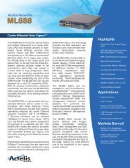
100 Series — Contact ClosuresClick! 100 — 16-Output Contact Closure ModuleCreates contact closure outputs from SmartSensor dataFeatures• 16 contact closures• 8 lanes, dual loop traps• Auto-bauds to SmartSensors• Auto-configures loop trap emulation• Keyed removable screw terminals• 16 LEDs for contact closure verification• 4 LEDs for mode selection• Compatible with SS105, SS125, SS200• Conformal coatedModels• Click! 100 DIN rail mountOperating Modes• Presence: dual-loop speed trap emulationwith dynamic closure duration• Pulse: dual-loop speed trap emulationwith fixed closure duration (125 ms)• Actuation: single loop emulation (truepresence)• One-Loop Speed: single loop emulationwith contact closure duration based onspeedContact closures are a common component in traffic controlsystems. The Click! 100 16-Output Contact Closure moduleconverts serial data from the <strong>Wavetronix</strong> SmartSensor intocontact closures, which can then be input into a data logger orattached to a relay to interface with other devices. The Click!100 is available in a standard, DIN rail-mountable format and iscompatible with the SmartSensor 105, 125 and 200 models.The Click! 100 offers four modes of operation: the Presenceand Pulse modes support dual-loop speed trap emulation; theActuation and One-loop Speed modes support single loopemulation. Each mode converts SmartSensor data into contactclosures accessible on the module’s 16 output channels. Fourcontrol LEDs on the Click! 100’s front panel display the variousmodes while an additional 16 LEDs provide visual verification ofthe contact closure outputs.Dual-loop Speed Trap EmulationThe Presence mode outputs a primary contact closure (loop 1)followed by a secondary contact closure (loop 2); the duration ofeach represents a vehicle’s duration in the emulated loop. Similarly,the Pulse mode outputs first a primary, and then a secondary,contact closure, but each output is a fixed duration of 125 ms.Single Loop EmulationThe Actuation mode signals true presence information with 5 msresolution. This mode can be used to signal a detection to a trafficcontroller or to increase the accuracy of occupancy data whentraffic is slowing or stopping. Meanwhile, the One-loop Speedmode outputs contact closures based on vehicle speed and length.Both of these modes only output contact closures on the Click!100’s primary channels.<strong>Wavetronix</strong>10Screw terminals pop out and snap in for easy device exchange without re-wiring.Easy Configuration and IntegrationThe Click! 100 auto-configures by pollingthe SmartSensor for loop spacing andbaud-rate information. Once the autoconfigurationis complete, the Click! 100defaults to Presence mode.Interfacing with the Click! 100 is easy.As illustrated below, keyed, removablescrew terminals can be wired before theunit is in place, reducing the chance formistakes. The keyed terminals guaranteethat the proper terminals are used for theprimary and secondary channels, andare a feature of all Click! DIN rail mountmodules.Contact <strong>Wavetronix</strong> and find out howthe Click! 100 can improve the contactclosure outputs of your traffic system. Seethe inside front cover for details.
T-BusConnectorPrimary ContactClosure OutputPrimary LEDsMode SwitchLED IndicatorsSecondary LEDsGroundSecondary ContactClosure OutputClick! 100 SpecificationsWeight:0.20 lbsPhysical Dimensions:4.5 in. × 4 in. × 0.9 in.Ambient Operating Temp: -34°C to +74°CHumidity:Up to 95% RHPower Supply Voltage:+10 to + 30 VDCRS-485 Voltage Range: -9 to +14 VDCBaud Rate Setup:Auto-detectBaud Rates:9,600 to 57,600 bpsPower Consumption:0.6 WCommunications:RS-485Contact Closure Outputs: 16Number of Lanes (Speed Trap): 8Ordering InformationClick! 100 DIN Rail Mount..........................................WX-SC-100Accessories20 AWG Shielded 2-Conductor Cable 9.5″.............. WX-SC-8555-position T-bus Screw Terminal.............................. WX-SC-652DIN Rail 9″.................................................................. WX-SC-650DIN Rail 12″........................................................WX-SC-650-012Related <strong>Products</strong>Click! 201 1 Amp Power Supply.................................WX-SC-201Click! 202 2 Amp Power Supply.................................WX-SC-202Click! 205 AC Surge Protector.................................. WX-SC-205Click! 206 0.5 Amp Circuit Breaker.......................... WX-SC-206SmartSensor...............................................................WX-SS-105SmartSensor HD.........................................................WX-SS-125SmartSensor Advance............................................... WX-SS-200More accessories and related products available.11
100 Series — Contact ClosuresClick! 172/174 — Contact Closure Rack CardsEasily integrates the <strong>Wavetronix</strong> SmartSensor with traffic controllersFeatures••••••Automatically sets baud rateSets signaling mode and enablessensor outputDisplays speed and detection countUses industry-standard RS-485 busFailsafeCompatible with NEMA TS1 and TS2,170, and 2070 traffic controllersConformal coated•Models• Click! 172 Rack Card: 2 channels• Click! 174 Rack Card: 4 channelsApplications• Signalized intersection control• Dynamic warning systemsOperating Modes• Presence: dual-loop speed trapemulation with dynamic closureduration• Pulse: dual-loop speed trap emulationwith fixed closure duration (125 ms)• Actuation: single loop emulation (truepresence)• One-Loop Speed: single loop emulationwith contact closure duration based onspeedAs traffic detection technologies have advanced, it hasgrown increasingly more challenging to incorporate theseintelligent devices into legacy systems. The Click! 172 and 174Contact Closure modules have been specifically designed toeasily integrate the <strong>Wavetronix</strong> SmartSensor with existingtraffic controllers, providing industry-standard contact closuresfor NEMA TS1, TS2, 170 and 2070 controllers.The Click! 172 and 174 modules are similar in most respects,but they do have some key differences that help differentiate thetwo: the 172 module provides two channels of contact closuresand occupies a single rack slot; the 174 module offers fourchannels of contact closures and fills two rack slots. Both areeasy to install and operate, with standard operations controlledby a three-position Settings toggle switch: the first two positionsare for configuration; the third position is for normal operation(see the illustration below right). Each toggle position representone part in a three-step process for configuring and operating theClick! 172 and 174 devices.Step OneWhen the toggle switch is set to position 1, the moduleautomatically connects to the SmartSensor associated with thatmodule. Once connected, users press the Select button to selectthe sensor’s output mode. The selected mode will be shown on theLED display. At the same time, the module will be configured togenerate the corresponding type of contact closure.Step ThreeMove the toggle switch to position 3 and the module begins normaloperation, providing contact closures based on its configuration.When a contact closure is being generated, the correspondingchannel LED lights up, making it easy to verify operation.While in normal operating mode, the module continuallychecks its connection with the SmartSensor. If the connection iscompromised for any reason, the module automatically enters afailsafe mode and signals a constant call on all channels.These three simple steps make it easy to integrate SmartSensor’sconsistently accurate vehicle detections with existing trafficcontrollers. Contact <strong>Wavetronix</strong> to find out how the Click! 172and 174 Contact Closure modules can be a vital part of your trafficsystem. See the front inside cover for details.SelectButtonSettingsPosition1SettingsPosition2SettingsPosition3<strong>Wavetronix</strong>Step TwoWhen the toggle switch is moved to position 2, the module is readyto map the SmartSensor’s outputs to contact closure channels.First, users specify a channel to configure by repeatedly pressingthe Channel button until the desired channel number is shown onthe LED display. Next, they assign a SmartSensor output to theselected channel by repeatedly pressing the Select button untilthe LED shows the desired output. Technicians simply repeat thisprocess for each contact closure channel.ChannelSelectorStep Step StepLEDIndicator12
RackConnectorSelectButtonSettingsSwitchLEDIndicatorChannelButtonChannelIndicatorsRS-485ConnectorsClick! 172/174 SpecificationsOperational FeaturesWeight:0.40 lbsCommunications:RS-485 ConnectionPhysical Dimensions:Ambient Operating Temp:Humidity:Contact Closure Outputs:4.5 in. x 1.13/2.32 in. x 7 in. (8 in.w/handle)-34°C to +75°CUp to 95% RH2/4 Card edge contactsBaud Rates:Configuration:Output Indicator:Display:9,600 bps to 57,600 bpsAuto configure w/SmartSensor2/4 Red LEDsDual 7 segment display w/powersaving disableElectrical SpecificationsSurge PropertiesMaximum Current:Power Supply Voltage:RS-485 Voltage Range:Closed Switch Resistance:45 mA+10 to +30 VDC-9 to +14 VDC100 OhmsDC Power:Peak Surge Current:Withstands differential DC powersurge voltage of up to 4 kV- Commonsurge voltage up to 4 kV10 kA (8 x 20us)Maximum Switch Current:Maximum Switch Voltage:Output Ratings:Output Power Dissipation:Output Surge Current:30 mA50 VDCOpto-isolator SemiconductorSwitch600 W100 AOrdering InformationClick! 172/174 Rack Cards....................WX-SC-172/WX-SC-174Accessories8” RS-485 Patch Cord (RJ-11)..................................WX-SC-66060” RS-485 Patch Cord (RJ-11)................................WX-SC-661More accessories and related products available.13
PR PU AC 1L1 2 3 45 6 7 8MADE IN USA www.wavetronix.comTM200 Series — Power ManagementPR PU AC 1L5 6 7 8MADE IN USA www.wavetronix.comTM100-240V AC InDC OK22.5-28.5 VDCTMWAVETRONIXTM24 VDC Outw w w . w a v e t r o n i x . c o m16ContactClosures1 2 3 45 6 7 89 10 11 1213 MODE 14 15 16PR PU AC 1L1 2 3 45 6 7 8MADE IN USA www.wavetronix.comClick! 200 — Surge ProtectorProtect devices from power surges over DC power and serial communication linesFeatures• Three-stage supression design:- First stage gas tubes- Second stage inductors and TVSdiodes- Third stage resettable fuses andvaristors• Convenient, hot-swappable power andcommunication buses• Surge protection for RS-485, RS-232and DC power• DIN rail mounted for quick installation• Pluggable screw terminals minimizeproblems due to incorrect wiring• Designed for use with other Click!devices• Conformal CoatedModels• Click! 200 DIN Rail MountPower surges are one of the most common reasons for thefailure of traffic devices installed in the field. The Click! 200Surge Protection module features a three-stage surge suppressiondesign that protects the <strong>Wavetronix</strong> SmartSensor and otherdevices from power surges over DC power and RS-232 and RS-485 communication lines.The Click! 200 surge protector is hot-swappable, and themodule features both protected and unprotected sides. Theunprotected side of the Click! 200 should be wired to the cablemost likely to conduct a power surge, and the surge ground (GND)on the unprotected side should be connected to earth ground. Forexample, in a pole-mount cabinet where all other lines cominginto the cabinet are protected, the most likely source for a surgeis the SmartSensor cable, so this cable should be wired to theunprotected side of a single Click! 200 module.Some installations require more than one Click! 200 devicefor complete surge protection. In the illustration below, theinstallation has cabling that runs underground from theSmartSensor to the traffic cabinet. In this example, the buriedcable is the most likely source of power surges and will requireone Click! 200 to protect the sensor and another to protect thecabinet. Technicians would mount one Click! 200 as close to thesensor as possible, connecting the cable from the sensor to themodule’s protected side; the second Click! 200 is mounted in thetraffic cabinet, and both ends of the buried cable are connectedto each Click! module’s unprotected side. If the distance betweensensor and cabinet is greater than 250 feet, it is recommended thatthe RS-232 line on the unprotected side remain unconnected, asRS-232 will not reliably communicate with SmartSensor at longerdistances.Effective surge protection is a vital part of a traffic system.Contact <strong>Wavetronix</strong> and find out how the Click! 200 SurgeProtection module can help protect your system’s components andyour agency’s investment. See the inside front cover for details.SmartSensor16ContactClosuresMODEProtectedFor a surge protector to be effective,it must be grounded!Click!200 1011 AMPAC to DCClick!101Click!400Click!201Click!TM10116ContactClosuresMODE<strong>Wavetronix</strong>SurgeDischargeUnprotectedUnprotectedClick!200 101Surge Groundis on theUnprotectedSide of theClick! 200SurgeDischarge14
T-BusConnectorPower ConnectorRS-485 ConnectorRS-232 ConnectorRS-485ConnectorRS-232ConnectorRS-232 ConnectorRS-485 ConnectorPower ConnectorClick! 200 SpecificationsWeight:Physical Dimensions:Ambient Operating Temp:Humidity:Lines Protected:Protected Types:RS-485 Surge:RS-232 Surge:DC Power:Peak Surge Current:0.30 lbs4.5 in. × 4 in. × 0.9 in.-34°C to +74°CUp to 95% RHRS-485, RS-232 with CTS/RTS, DCPowerMulti-stageDifferential and Common ModesDifferential and Common Modesup to 4 kV, Clamping Voltage 8 VDCDifferential and Common Modesup to 4 kV, Clamping Voltage 11 VDCDifferential and Common Modesup to 4 kV, Clamping Voltage 26 VDC10 kA (8 X 20 us)Ordering InformationClick! 200 DIN Rail Mount......................................... WX-SC-200Accessories9.5” 20 AWG Shielded 2 Conductor Cable.............. WX-SC-8555-position T-bus Screw Terminal.............................. WX-SC-652DIN Rail 9″.................................................................. WX-SC-650DIN Rail 12″........................................................WX-SC-650-012SmartSensor Cable..........................................WX-SC-H701-040Related <strong>Products</strong>Click! 201 1 Amp Power Supply.................................WX-SC-201Click! 202 2 Amp Power Supply.................................WX-SC-202Click! 205 AC Surge Protector.................................. WX-SC-205Click! 206 0.5 Amp Circuit Breaker.......................... WX-SC-206SmartSensor...............................................................WX-SS-105SmartSensor HD.........................................................WX-SS-125SmartSensor Advance............................................... WX-SS-200More accessories and related products available.Power Consumption:0 W, Passive15
200 Series — Power ManagementClick! 201/202 — Power SupplyConverts AC to DC and supplies power to all Click! DIN rail mount modulesFeatures• Converts AC to DC power• DIN rail mounted• Meets NEMA TS2-1998 environmental specification• UL listed• Internal surge protection• Pluggable keyed screw terminals• DC OK LEDModels• Click! 201 DIN Rail Mount: 1 Amp @ 24 VDC• Click! 202 DIN Rail Mount: 2 Amp @ 24 VDCOne of the most important parts of any Click! installation is thepower supply. Often technicians need to incorporate customtransformers or adapters for every communication product in acabinet. The Click! 201 and 202 Power Supply modules makepower management easy by providing power to every Click!DIN rail mounted product. Simply hook up a Click! power supplymodule and attach the power lines to the T-bus to supply power toevery Click! module connected to that T-bus.The Click! 201 and 202 modules convert AC to DC power,outputting 1 or 2 amps respectively at +24 VDC. All Click!devices have been thoroughly tested to work with either module.The illustration below shows a common power solution using theClick! 202 2-amp power supply; a Click! 205 surge suppressor toprotect the Click! 202 from AC power surges; and a Click! 206circuit breaker that uses replaceable fuses and allows connecteddevices to be quickly powered on or off.In this example, the AC line is connected to the bottom of theClick! 206 circuit breaker, and continues from the top of the Click!206 to the bottom of the Click! 205. AC ground and neutral godirectly into the bottom of the Click! 205; the AC line and neutralcontinue from the top of the Click! 205 into the top of the Click!202 power supply. The Click! 202 then converts the AC into DCpower that comes out of the bottom of the Click! 202, where it canbe used by other Click! modules.When used together, these modules provide the easiest wayto meet the power requirements of the Click! communicationmodules. Contact <strong>Wavetronix</strong> and find out how the Click! 201 and202 Power Supply modules can simplify the power managementneeds of your system. See the inside front cover for details.<strong>Wavetronix</strong>A typical power solution using the DIN rail mountable Click! 202.16
AC PowerConnectorDC OKDCAdjustDC PowerConnectorClick! 201/202 SpecificationsWeight:Physical Dimensions:Ambient Operating Temp:Humidity:Input Voltage Range:0.46/0.55 lbs4.5 in. × 3.9 in. × 0.9 in./4.5 in. × 3.9 in. × 1.7 in.-25°C to +74°CUp to 95% RH+85 to +264 VACOutput Voltage: +24 VDC ±1%Output Current:Internal Fuse:Transient Surge Protection:Frequency:Shock:1 A/2 AT1.25 AL 250 V/2.5 ATVaristor45 Hz to 65 Hz30 g all spaces and directionsOrdering InformationClick! 201 DIN Rail Mount..........................................WX-SC-201Click! 202 DIN Rail Mount..........................................WX-SC-202Accessories12 AWG Power Cable................................................. WX-SC-6408’ Male Plug Power Cord........................................... WX-SC-669Related <strong>Products</strong>Click! 206 0.5 Circuit Breaker.................................. WX-SC-206Click! 206 2 Amp Circuit Breaker....................... WX-SC-206-02Click! 206 10 Amp Circuit Breaker......................WX-SC-206-1020 Amp Circuit Breaker............................................. WX-SC-863Click! 205 AC Surge Protector.................................. WX-SC-205Click! 200 Surge Protector........................................ WX-SC-200120 VAC Relay............................................................ WX-SC-860More accessories and related products available.17
300 Series — Wired CommunicationClick! 301 — Serial to Ethernet ConverterEasily adds network connectivity to serial devicesFeatures•••Converts half-duplex serial to Ethernetand vice-versaIncludes multiple communication portsUses either Ethernet or serial interfacesto configure baud ratesPassed testing for the NEMA TS2-1998environmental specificationSupports the Click! Supervisor for easysetup and configurationAuto-reset of inactive socketsConformal coated••••Applications• Controller Closed Loop Ethernet• Sensor to EthernetDriver Library• 170 Controller 1200 bps• Point to Point• Point to Multipoint• Opticom• SmartSensor (105, 125, 200)• Others<strong>Wavetronix</strong>18Models• Click! 301 DIN Rail Mount• Click! 301 Rack Card• Click! 301 170 Controller CardAs communication infrastructures grow, networked accessto traffic equipment becomes a more common, more usefuloption for traffic agencies. Many devices in a typical traffic cabinetuse RS-232 or RS-485 serial communications and cannot beaccessed over a TCP/IP network. The Click! 301 Serial to EthernetConverter brings network connectivity to serial devices, allowingagencies to take advantage of existing TCP/IP infrastructures.The Click! 301 is an intelligent converter designed for easyintegration. It provides simple connectivity between serial andEthernet devices, quickly adding easy network access to serialequipment and enabling seamless communication betweendevices. Easy-to-use configuration tools simplify the installationSimplified Driver Configurationprocess; with the “click and use” design of the Click! line, userscan literally have the Click! 301 installed, configured and runningin a matter of minutes.Configuring devices for access to a TCP/IP network can be adaunting task. Typically, dozens of specialized parameters must beset to specific values in order for the configuration to be successful.<strong>Wavetronix</strong> has simplified this process by providing drivers forvarious types of devices. These drivers only require a few piecesof key information and automatically set the rest of the parametersto acceptable settings. This simplified driver technology literallyreduces the configuration process down to a single screen and canbe accessed using Click! Supervisor, the configuration softwarefor Click! devices. Users can evensave configurations to a file that canthen be used as the starting point foradditional device configurations.The Click! 301 also features multipleconnection points. Technicians canuse the RS-232 DB-9 connector onthe module’s front panel, the T-busor the pop-out RS-485 connectorto establish serial connections forEthernet conversions. Any deviceattached to these connectors cancommunicate with the Click! 301and immediately becomes part of thenetwork.The Click! 301 easily expandssystems and adds connectivity toserial-based networks. Contact<strong>Wavetronix</strong> to find out how the Click!301 can help add network accessto your traffic system. See the frontinside cover for details.
T-BusConnectorRS-485ConnectorEthernetConnectorLED IndicatorsRS-232ConnectorModeSwitchClick! 301 SpecificationsWeight:Physical Dimensions:0.20 lbs4.5 in. x 4 in. x 0.9 in.Ordering InformationClick! 301 DIN Rail Mount......................................... WX-SC-301Click! 301 Rack Card.......................................WX-SC-301-RACKClick! 301 170 Controller Card........................WX-SC-301-170AAmbient Operating Temp.:Humidity:Power Supply Voltage:RS-485 Voltage Range:RS-232 Voltage Range:Baud Rate Setup:RS-485 Turnaround Time:-34°C to +74°CUp to 95% RH+10 to +30 VDC-9 to +14 VDC±25 VDCAuto-detected1.1 mSPower Consumption: 1 WCommunications:Baud Rates:Ethernet Speed:Ethernet, RS-485 & RS-232DCE300 to 115,200 bps10/100 Mb Auto-negotiateAccessoriesEthernet Inline Surge................................................. WX-SC-668Straight-through RS-232 Modem Cable................... WX-SC-6796’ CAT5 Ethernet Cable............................................. WX-SC-6909.5” 20 AWG Shielded 2 Conductor Cable.............. WX-SC-8555 Position T-bus Screw Terminal............................... WX-SC-652DIN Rail- 9”................................................................. WX-SC-650DIN Rail- 12”.......................................................WX-SC-650-012Related <strong>Products</strong>Power Over Ethernet & Surge Protection................. WX-SC-203CAT5 Lightning Surge Protector................................ WX-SC-2088 Port Ethernet Switch.............................................. WX-SC-600Click! 202 2 Amp Power Supply.................................WX-SC-202More accessories and related products available.19
RS-485300 Series — Wired CommunicationClick! 304/305 — RS-232 to RS-485/USBImproves serial communications and easily expands serial networksFeatures• Click! 304 converts data between RS-232 and RS-485• Click! 305 converts RS-232 and RS-485 to USB• Auto-bauds to serial port devices• Meets NEMA TS2 1998 environmentalspecifications• Conformal CoatedModels• Click! 304/305 DIN Rail Mount• Click! 304/305 Rack Card• Click! 304/305 170 Controller CardApplications• Convenient connectivity to laptopthrough USB• Range extension of an RS-232 bus• RS-485 repeater/range extenderDriver Library• SmartSensor (105, 125, 200)• OthersSerial communication is commonly used in traffic systems,but not all devices support both RS-232 and RS-485communications. The Click! 304 and 305 devices are basic dataconversion modules that quickly translate communication inputson any port and output the communication on all other ports at thesame time. All Click! communication devices operate the sameway, ensuring that a system can support RS-232 and RS-485communications regardless of what Click! module is being used.The Click! 304 converts half-duplex RS-232 to half-duplexRS-485 and vice versa. One application for the Click! 304 isextending an RS-232 bus: if a traffic sensor or other RS-232 serialdevice exceeds the 250 foot range, the Click! 304 can be used toconvert RS-232 to RS-485, extending the range of transmissionup to 2000 feet, even with surge suppressors on both ends of thetransmission line.The Click! 305 converts serial communications but also addsa port for serial to USB conversions. With this device, laptopcomputers that do not have built-in RS-232 ports can stillcommunicate with standard serial devices. After installing theappropriate driver, technicians can plug a USB cable between thelaptop and the Click! 305 and communicate with all serial devicesconnected to the Click! 305 module.The Click! 304 and 305 modules improve serial communicationsand extend the capabilities of a serial network. Contact <strong>Wavetronix</strong>to find out how these devices can ensure the reliability of yourserial communications. See the front inside cover for details.RS-485304RS-485304RS-485RS-485RS-485RS-232RS-232<strong>Wavetronix</strong>Communication into one port is directed out all other ports simultaneously.20
T-BusConnectorRS-485ConnectorRS-485ConnectorLED IndicatorsRS-232ConnectorMode SwitchClick! 304/305 SpecificationsWeight:0.20 lbsPhysical Dimensions:4.5 in. × 4 in. × 0.9 in.Ordering InformationClick! 304/305 DIN Rail Mount....................... WX-SC-304/305Click! 304/305 Rack Card.....................WX-SC-304/305-RACKClick! 304/305 170 Controller Card......WX-SC-304/305-170AAmbient Operating Temp:Humidity:Input Voltage Range:RS-485 Voltage Range:RS-232 Voltage Range:Baud Rates:RS-485 Turnaround Time:Power Consumption:Click! 304 Communications:Click! 305 Communications:Communication Direction:-34°C to +74°CUp to 95% RH+10 to +30 VDC-9 to +14 VDC±25 VDC300 to 115,200 bps1.1 ms0.25 WRS-485 and RS 232 DCEUSB 1.1, RS-485 and RS-232DCEBidirectional, Half DuplexAccessoriesDB9F to DB9F Null Modem Adapter......................... WX-SC-695Straight-through RS-232 Modem Cable................... WX-SC-679RJ-11 Patch Cord 60″................................................ WX-SC-66120 AWG Shielded 2-Conductor Cable 9.5″.............. WX-SC-8555-position T-bus Screw Terminal.............................. WX-SC-652DIN Rail 9″.................................................................. WX-SC-650DIN Rail 12″........................................................WX-SC-650-012Related <strong>Products</strong>Click! 200 Surge Protector........................................ WX-SC-200Click! 201 1 Amp Power Supply.................................WX-SC-201Click! 202 2 Amp Power Supply.................................WX-SC-202More accessories and related products available.21
400 Series — Wireless CommunicationClick! 400 — Serial to 900 MHz RadioA wireless cable replacement system with extended rangeFeatures••••••Converts half-duplex serial to 900 MHzand vice-versaAuto-bauds to serial devicesIncludes multiple communication portsUses either 900 MHz or serial interfacesto configure the devicePoint to multipointConformal coatedModels• Click! 400 DIN Rail Mount• Click! 400 Rack Card• Click! 400 170 Controller CardApplications• Direct cable replacement with a distanceof over 20 miles (line of sight)• Controller Closed Loop 900 MHzDriver Library• SmartSensor (105,125,200) Server• SmartSensor (105,125,200) Client• ECONOLITE Master• ECONOLITE Local• Others<strong>Wavetronix</strong>Modern, advanced technologies are allowing transportationagencies to deploy traffic systems over greater distancesand in even more remote locations. The Click! 400 is a wireless,spread-spectrum radio that supports serial communication overline-of-sight distances of up to 20 miles. With the Click! 400,agencies can retrieve data from sensors in remote areas, andthey can access several sensors at once from one location. TheClick! 400 also simplifies installation when the sensor and thetraffic cabinet with which it needs to communicate are located onopposite sides of a roadway.One of the challenges of setting up long-distancecommunications is debugging a faulty link and finding out wheredata is getting lost. Communication problems can be caused by anumber of things: a sensor may not be working properly; radiosmay not be set up to communicate with each other correctly;or different devices may not be running at the same baud rate.ServerZ YX W VU TS R QPO NML K JBlinking Green =Data beingtransmitted.Blinking Green =Good Data.Blinking Yellow =Bad Data.Solid Yellow =No Data.I HGFEDCBAClick! 400’s LEDs provide visual verification of successful communication.<strong>Wavetronix</strong> has created several easy-to-use tools to simplify thetesting and debugging of Click! devices, and one of the mosteffective tools is a link test.To test the link of a Click! 400, technicians need to set onemodule as a server by pressing and holding the push-button modeswitch on the Click! 400’s front panel until the blue “WirelessLink” LED begins to blink; they need to set another Click! 400module as a client by pressing and holding the mode switch untilthe blue “Wireless Link” LED is solid. Click! 400 modules thathave been auto-bauded to a SmartSensor are set as clients bydefault (see the Click! 402 article on page 26 for more informationon how to auto-baud a Click! module).When a Click! 400 is in server “link test” mode, the red andblue LEDs will stay on and the green LED will blink, indicatingthat data is being transmitted (See the illustration below left).When the module is in client “link test” mode, the red LEDwill stay on: if the client and server areconnected, then the blue LED will comeon; if the client is not receiving data fromthe server, the yellow LED will come on; ifthe yellow LED is blinking, then the clientis receiving bad data; and if the green LEDis blinking, then the module is receivinggood data in the right order. Technicianscan exit the “link test” mode by quicklypressing and releasing the mode switch.Easy-to-use debugging tools makethe Click! 400 the perfect solution forlong distance communications. Contact<strong>Wavetronix</strong> to find out how the Click! 400can improve the communications in yourtraffic system. See the inside front coverClientfor details.22
T-BusConnectorRS-485ConnectorAntennaConnectorLED IndicatorsRS-232ConnectorModeSwitchClick! 400 SpecificationsWeight:Physical Dimensions:Ambient Operating Temp:Humidity:Power Supply Voltage:RS-485 Voltage Range:RS-232 Voltage Range:RS-485 Turnaround Time:Power Consumption:Communications:Baud Rates:RF Transmit Power:RF Connector:0.20 lbs4.5 in. × 4 in. × 0.9 in.-34°C to +74°CUp to 95% RH+10 to +30 VDC-9 to +14 VDC±25 VDC1.1 mS1.6 W Typical900 MHz, RS-485 and RS-232DCE1,200 to 115,200 bps1 W maximum (adjustable)Reverse Polarized SMAOrdering InformationClick! 400 DIN Rail Mount.....................................................WX-SC-400Click! 400 Input File Rack..................................... WX-SC-400-RACKClick! 400 170 Controller Card............................... WX-SC-400-170AAccessoriesUniversal Antenna Mount w/ U-Bolt Kit................... WX-SC-451Straight-through RS-232 Modem Cable................... WX-SC-6791′ N-Male to RPSMA Male Cable............................... WX-SC-6659.5″ 20 AWG Shielded 2-conductor Cable............... WX-SC-8555-position T-bus Screw Terminal.............................. WX-SC-652DIN Rail 9″.................................................................. WX-SC-6507″ 900 MHz Omni-directional Antenna.................... WX-SC-4615 dBi Omni-directional 900 MHz Antenna............... WX-SC-4529 dBi Directional 900 MHz Yagi Antenna................. WX-SC-453Related <strong>Products</strong>N-Female to N-Female Bulkhead Coaxial Surge......WX-SC-207Click! 201 1 Amp Power Supply.................................WX-SC-201Click! 202 2 Amp Power Supply.................................WX-SC-202More accessories and related products available.23
400 Series — Wireless CommunicationClick! 401 — Serial to 802.11b RadioConvenient remote access for mobile data collectionFeatures•Provides TCP/IP access to serialdevicesIncludes TCP/IP stack with embeddedweb server interfaceConverts data between RS-485 and802.11b protocolsConverts data between RS-485 andRS-232 protocolsAuto-bauds to serial port devicesOffers password and 64/128-bit WEPprotectionMeets NEMA TS2 1998 EnvironmentalSpecificationsAuto reset of inactive socketsConformal coated••••••••Models• Click! 401 DIN Rail Mount• Click! 401 Rack Card• Click! 401 170 Controller CardApplications• Remote Data Access• Wire Replacement• Cabinet to Cabinet NetworkDriver Library• SmartSensor (105, 125, 200)• Point-to-point• Point-to-multipoint• OthersMobile data collection from in-the-field devices posesa number of problems. In addition to environmentalconditions, technicians also take huge risks whenever theyattempt to work near a road, especially on corridors with a heavytraffic flow. The Click! 401 Serial to 802.11b radio is an easy wayto make mobile data collection safer, more convenient and moreefficient. The Click! 401 can streamline the mobile data collectionprocess; technicians don’t even need to leave their vehicles butcan park, establish a wireless connection between their laptopand the Click! 401 in the cabinet and begin downloading data.The Click! 401 allows serial devices to communicate wirelesslyby converting either RS-232 or RS-485 to 802.11b and vice versa.The 401 module features an embedded TCP/IP stack that convertsserial data streams into Internet packets; each serial deviceconnected to a Click! 401 will have an IP address so it can beaccessed remotely and securely.Configuring the Click! 401 is easy. The Click! Supervisorconfiguration tool provides a simple interface that allows users tomake point to point, point to multi-point, and basic SmartSensorconnections.Click! 401 improves mobile data collection by protectingtechnicians from environmental elements; by protectingtechnicians from the dangers of working near a busy roadway;and by improving the efficiency of a mobile data collection system.Contact <strong>Wavetronix</strong> to find out if Click! 401 is the right answer foryour system’s mobile data collection needs. See the inside frontcover for details.<strong>Wavetronix</strong>With Click! 401, traffic datacan be downloaded frominside a vehicle.24
T-BusConnectorRS-485ConnectorAntennaConnectorLED IndicatorsRS-232ConnectorModeSwitchClick! 401 SpecificationsWeight:Physical Dimensions:Ambient Operating Temp:Humidity:Power Supply Voltage:RS-485 Voltage Range:RS-232 Voltage Range:RS-485 Turnaround Time:Power Consumption:Communications:Baud Rates:RF Transmit PowerRF Connector0.20 lbs4.5 in. × 4 in. × 0.9 in.-34°C to +74°CUp to 95% RH+10 to +30 VDC-9 to +14 VDC±25 VDC1.1 mS2 W802.11b, RS-485 and RS-232DCE300 to 115,200 bps100 mW Maximum (adjustable)Reverse Polarized SMAOrdering InformationClick! 401 DIN Rail Mount......................................... WX-SC-401Click! 401 Rack Card.......................................WX-SC-401-RACKClick! 401 170 Controller Card........................WX-SC-401-170AAccessoriesUniversal Antenna Mount with U-Bolt Kit................ WX-SC-451Straight-through RS-232 Modem Cable................... WX-SC-6791’ N male to RPSMA Male Cable............................... WX-SC-6659.5” 20 AWG Shielded 2 Conductor Cable.............. WX-SC-8555 Position T-bus Screw Terminal............................... WX-SC-652DIN Rail 9”.................................................................. WX-SC-650DIN rail 12″.........................................................WX-SC-650-012N-Female to N-Female Bulkhead Coaxial Surge......WX-SC-2072.4GHz 2.5dBi Indoor Whip Antenna.......................WX-SC-84612dBi Mini Directional Antenna................................ WX-SC-455Related <strong>Products</strong>Click! 202 2 Amp Power Supply.................................WX-SC-202Click! 201 1 Amp Power Supply................................WX-SC-201More accessories and related products available.25
400 Series — Wireless CommunicationClick! 402 — Serial to GPRS RadioProvides cell-based remote access to serial traffic equipmentFeatures• TCP/IP addressable• Optional static IP address• Accepts inbound connections• Uses GPRS network• Auto-connects to network• Approved Cingular network device• Auto reset of inactive sockets• Conformal coatedModels• Click! 402 DIN Rail Mount• Click! 402 Rack Card• Click! 402 170 Controller CardApplications• Remote data download• Remote managementDriver Library• SmartSensor (105, 125, 200)• Others<strong>Wavetronix</strong>26General Packet Radio Service (GPRS) is a powerfulcommunication protocol that allows cell phone serviceproviders to allocate portions of their cell bandwidth for datatransmissions. The Click! 402 Serial to GPRS radio takesadvantage of this technology, adding cell-based TCP/IP access toany attached serial device.Once service is established, users can connect to their serialequipment without having to run communication lines to remotecabinets. As a result, users can access serial devices in the fieldand download data or change configuration settings remotelyfrom their desk, saving agencies the time and expense required tovisit each remote location to collect data or manage devices.Testing connection with auto-baud.123Hold mode switchuntil green lightis on.Red light will flashwhile autobauding.Success (yellowlight flashes withdata).Failure (solid yellowlight).Like all Click! communication modules, the Click! 402 featuresa mode switch that allows users to cycle through various modes ofoperation, including factory reset and auto-baud. The auto-baudmode simplifies the connection process because users do not needto know the baud rate of an attached serial device in order tosuccessfully link the device to the communications network.To activate the auto-baud mode, users press and hold themode switch until the solid green LED comes on. As the deviceautomatically determines the baud rate of the connected device,the green LED will be solid and the red LED will be on butblinking every few seconds. As illustrated below, there are twopossible outcomes for the auto-baud process: if the auto-baud issuccessful, then the red LED will be solid and all other LEDs willbe off (the yellow LED may flash intermittently as the modulereceives data); if the auto-baud fails, then both the red and yellowLEDs will be solid.Auto-baud can also be used as a diagnostic tool to verify thecommunication link without the use of external test equipment.Consider a system that places three cabinets between a sensorand the final destination. After all devices have been installed,users can test the communication flow by running auto-baud on aClick! device in Cabinet A – the cabinet farthest from the sensor.A successful test means that communication with the sensor is intact, and a failed test means the communication link is broken.If the link is broken, then users would run auto-baud on a Click!device in Cabinet B – the cabinet next closest to the sensor:success in Cabinet B would indicate the link is broken betweenCabinets A and B. Once the link is repaired, users would run autobaudagain in Cabinet A; a successful auto-baud means that thelink has been properly repaired.Remote access, combined with auto-baud’s configuration anddiagnostic capabilities, makes the Click! 402 an invaluable partof any traffic system. Contact <strong>Wavetronix</strong> to find out how to addflexible, cell-based TCP/IP to your serial traffic devices. See theinside front cover for details.
T-BusConnectorRS-485ConnectorAntennaConnectorLED IndicatorsRS-232ConnectorMode SwitchClick! 402 SpecificationsWeight:Physical Dimensions:Ambient Operating Temp:Humidity:Power Supply Voltage:RS-485 Voltage Range:RS-232 Voltage Range:Baud Rates:RS-485 Turnaround Time:Power Consumption:Communications:RF Transmit Power:RF Connector:0.20 lbs4.5 in. × 4 in. × 0.9 in.-34°C to +74°CUp to 95% RH+10 to +30 VDC-9 to +14 VDC±25 VDC1200 to 115,200 bps1.1 ms2 WGPRS, RS-485 and RS-232 DCE1 WReverse Polarized SMAOrdering InformationClick! 402 DIN Rail Mount......................................... WX-SC-402Click! 402 Rack Card.......................................WX-SC-402-RACKClick! 402 170 Controller Card........................WX-SC-402-170AAccessoriesUniversal Antenna Mount w/ U-bolt Kit................... WX-SC-451Straight-through RS-232 Modem Cable................... WX-SC-679N Male to RPSMA Male Cable................................... WX-SC-66520 AWG Shielded 2-conductor Cable 9.5″............... WX-SC-8555-position T-bus Screw Terminal.............................. WX-SC-652DIN Rail 9″.................................................................. WX-SC-650DIN Rail 12″........................................................WX-SC-650-012N Female to N Female Bulkhead Coaxial Surge.......WX-SC-207Cellular/PCS/GPRS Antenna..................................... WX-SC-854Related <strong>Products</strong>Click! 201 1 Amp Power Supply.................................WX-SC-201Click! 202 2 Amp Power Supply.................................WX-SC-202More accessories and related products available.27
400 Series — Wireless CommunicationClick! 403 — Serial to Bluetooth® RadioEasily adds the convenience of Bluetooth to traffic devicesFeatures• Converts half-duplex serial communicationto Bluetooth® and vice-versa• Auto-bauds to serial devices• Includes two RS-232 ports and twoRS-485 ports for device pass-through• Uses either Bluetooth® or serialinterface to configure the device• Conformal coatedModels• Click! 403 DIN Rail Mount• Click! 403 Rack Card• Click! 403 170 Controller CardApplications• Direct cable replacement with adistance of 150 feet (in anon-metal cabinet)• Monitor and configure sensors withoutphysically connecting to the sensorDriver Library• SmartSensor (105, 125, 200)• OthersSerial communications are commonly used in traffic systems, butmost new laptops and Pocket PC® devices do not have serialports, so they cannot be used to configure serial devices. Also, mosttraffic system installations require that technicians be able to monitortraffic as they configure devices; on busy roadways, a technicianmay need to connect to a sensor from across the roadway, from alocation upstream from the sensor, or from inside a vehicle. Serialcommunications do not offer this level of flexibility or convenience.The Click! 403 Serial to Bluetooth® radio solves theseproblems by providing untethered, wireless connections toserial devices. With a Click! 403 and a laptop or Pocket PC thatsupports Bluetooth, it is possible to quickly make wireless serialconnections and to configure and retrieve data without physicallyconnecting to the installed equipment.As illustrated below, wireless Bluetooth connections can be apowerful tool in a traffic monitoring system. The Click! 403 has a lineof-sightrange of up to 150 feet if installed in a non-metal cabinet; ifthe cabinet is metal, simply keep the cabinet door open. A techniciancan stand at the side of a road or in a bucket truck and configure aSmartSensor using a laptop or Pocket PC to communicate with aClick! 403 installed in a nearby traffic cabinet.Contact <strong>Wavetronix</strong> to find out how the Click! 403 can add thepower of Bluetooth to your traffic system. See the inside frontcover for details.The Click! 403 allows for wireless configuration.<strong>Wavetronix</strong>28
T-BusConnectorRS-485 ConnectorRS-232 ConnectorLED IndicatorsRS-232ConnectorModeSwitchClick! 403 SpecificationsWeight:Physical Dimensions:0.20 lbs4.5 in. × 4 in. × 0.9 in.Ordering InformationClick! 403 DIN Rail Mount......................................... WX-SC-403Click! 403 Rack Card...................................... WX-SC-403-RACKClick! 403 170 Controller Card....................... WX-SC-403-170AAmbient Operating Temp: -34°C to +74°CHumidity:Up to 95% RHPower Supply Voltage: +10 to +30 VDCRS-485 Voltage Range: -9 to +14 VDCRS-232 Voltage Range: ±25 VDCRS-485 Turnaround Time: 1.1 mSPower Consumption: 0.5 WCommunications:Bluetooth, RS-485 and RS-232 DCEBaud Rates:1,200 to 115,200 bpsAccessoriesStraight-through RS-232 Modem Cable................... WX-SC-6799.5” 20 AWG Shielded 2 Conductor Cable.............. WX-SC-8555-position T-bus Screw Terminal.............................. WX-SC-652DIN Rail 9″.................................................................. WX-SC-650DIN Rail 12″........................................................WX-SC-650-012Related <strong>Products</strong>Click! 201 1 Amp Power Supply.................................WX-SC-201Click! 202 2 Amp Power Supply.................................WX-SC-202More accessories and related products available.RF Transmit Power:RF Connector:50 mW Effective (adjustable)N/A, Internal Antenna29
700 Series — Fiber-Optic CommunicationClick! 700/701 — Serial to Fiber-Optic ConvertersAllows serial-based traffic systems to communicate over existing fiber-optic networksFeatures• Converts data between RS-485 andFiber-optic protocols• Converts data between RS-485 andRS-232 protocols• Auto-bauds to serial devices• Provides fiber-optic link test• Conformal coatedModels• Click! 700/701 DIN Rail Mount• Click! 700/701 Rack Card• Click! 700/701 170 Controller CardApplications• Last mile connectivity• TOC Network• Cabinet-to-cabinet network• Remote data access• Master to local controllerDriver Library• SmartSensor (105,125,200)• OthersMany cities have a fiber-optic infrastructure in place and needa way to integrate it with their traffic systems. The Click!700 and 701 Serial to Fiber-optic Converter modules are a simpleway to link serial data devices with an existing fiber-optic network,especially for that all-important “last-mile” connection. Bothmodules use multi-mode optics; the Click! 700 has a maximumrange of 1 mile; the range of the Click! 701 reaches up to 2 miles.Form FactorsLike all Click! communication products, the Click! 700 and 701are available in three form factors that support a wide array ofinstallation options.The DIN rail mount form factor’s compact size and convenientconnection methods make it an ideal choice for many crowdedcabinets. <strong>Wavetronix</strong> offers additional Click! DIN rail mountdevices for power, power conditioning, communication, andsignaling.The Click! rack cards plug directly into a cabinet’s rack andtake their power from the backplane for hassle-free operation. Allyou need to use a Click! rack card is a free slot in your rack.The Click! 170 Controller Modem card extends the reach of170 controllers without requiring custom programming. The serialinterface between the controller and the Click! device provides atransparent data path to a communications engine that connectsthe 170 to the outside world.Simple ConfigurationThe Click! Supervisor software tool provides simple access to thefew configuration parameters required to set up a communicationslink. Setup is especially quick and easy when you use one ofthe simplified drivers included with Click! Supervisor.<strong>Wavetronix</strong>DIN RailMount170 ControllerModem CardRack CardOne tool configures all three Click! 700 form factors.Modular DesignEach Click! product features a modular design. For example, allthree Click! 700 and 701 form factors are configured and operatein exactly the same way; the same circuit board found in the DINrail mount version is used as a daughter board in the rack card and170 Controller modem card versions. This same modular design isfound in all Click! communication converters.Three form factors and only one configuration process makesthe Click! product line a perfect solution for simple systemexpansion. Contact <strong>Wavetronix</strong> to find out how the Click! 700 and701 can help your system take advantage of existing fiber-opticnetworks no matter what installation option is required. See thefront inside cover for details.30
T-BusConnectorRS-485ConnectorFiberConnectorsLED IndicatorsRS-232ConnectorModeSwitchClick! 700/701 SpecificationsWeight:0.20 lbsPhysical Dimensions:4.5 in. × 4 in. × 0.9 in.Ambient Operating Temp: -34°C to +74°CHumidity:Up to 95% RHPower Supply Voltage:+10 to +30 VDCRS-485 Voltage Range: -9 to +14 VDCRS-232 Voltage Range: ±25 VDCRS-485 Turnaround Time: 1.1 mSPower Consumption:0.6 WCommunications:Fiber, RS-485 and RS-232 DCEOrdering InformationClick! 700/701 DIN Rail Mount........................ WX-SC-700/701Click! 700/701 Rack Card......................WX-SC-700/701-RACKClick! 700/701 170 Controller Card........WX-SC-700/701-170AAccessoriesStraight-through RS-232 Modem Cable................... WX-SC-6799.5″ 20 AWG Shielded 2-conductor Cable............... WX-SC-8555-position T-bus Screw Terminal.............................. WX-SC-652DIN Rail 9″.................................................................. WX-SC-650DIN Rail 12″........................................................WX-SC-650-012Related <strong>Products</strong>Click! 202 2 Amp Power Supply.................................WX-SC-202Click! 201 1 Amp Power Supply.................................WX-SC-201Baud Rates:Wavelength:Maximum Distance:Fiber Type:300 to 115,200 bps820 nm / 1300 nm1 mile / 2 milesMultimode with ST connectorMore accessories and related products available.31
800 Series — <strong>Traffic</strong> ApplicationsClick! 800 — Alert ModuleA versatile device perfect for a variety of traffic applicationsFeatures• Filters vehicle detection data• Compatible with SS105 & SS125• User configurable call duration• User configurable polling interval• Automatically starts/stops polling forvehicle detection data• LED display for normal/configurationmodes• Conformal CoatedFilters• Length• Speed• Length AND speed• Length OR speed• Minimum speed OR maximum speedModels• Click! 800 DIN Rail MountApplications• Truck Rollover Warning• Queue Detection• Overspeed DetectionDriver Library• Overspeed• Underspeed• MaxLength• Truck Overspeed• Others<strong>Wavetronix</strong>32<strong>Wavetronix</strong> has taken the simple connectivity, affordabilityand reliability of the Click! product line and is creating aseries of devices designed for more complex traffic applications.The versatile Click! 800 Alert module is the first of these devices.It filters the event data it receives from a traffic sensor; pairinga Click! 800 module with the <strong>Wavetronix</strong> SmartSensor HDproduces a highly accurate system perfect for a number ofdifferent applications.The Click! 800 works by polling a SmartSensor at userdefinedintervals. As events are received from the sensor, themodule filters the data based on vehicle speed and length. Eventsthat meet the user-defined threshold are passed on to a Click!contact closure module, while events that do not meet the criteriaare ignored. The data can be transmitted to the Click! 800 overany Click! communication module, creating a low-cost, easy-toinstallsystem.The illustration below shows a common deployment using theClick! 800 in a Truck Rollover Warning system. In this example,a SmartSensor HD has been installed on the off-ramp to trackvehicles and speeds. This data is sent wirelessly from the sensorto a Click! 800 module which is configured to look for vehicleslonger than 20 feet traveling over 50 mph. If the data meets thiscriteria, it is passed onto a Click! 100 Contact Closure module,which interfaces with a relay that activates the flashers on thewarning sign.The same Click! 800 module can be used in a queue detectionsystem as well. Instead of filtering vehicles longer than 20 feettraveling over 50 mph, the Click! 800 can be configured to filtervehicles traveling slower than 20 mph. The contact closure canthen activate a variable message sign warning drivers of theslowdown ahead.Combined with SmartSensor’s consistent accuracy and theversatility of the Click! communication products, the Click! 800is a powerful tool for sophisticated traffic applications. Contact<strong>Wavetronix</strong> to find out how the Click! 800 can improve yourtraffic systems. See the inside front cover for details.Truck Rollover Warning System
T-BusConnectorRS-485ConnectorUSB 1.1ConnectorLEDIndicatorsRS-232ConnectorModeSwitchClick! 800 SpecificationsWeight:Physical Dimensions:Ambient Operating Temp:Humidity:Power Supply Voltage:RS-485 Voltage Range:RS-232 Voltage Range:RS-485 Turnaround Time:Power Consumption:Communications:Baud Rates:Communication Direction:0.20 lbs4.5 in. × 4 in. × 0.9 in.-34°C to +74°CUp to 95% RH+10 to +30 VDC-9 to +14 VDC±25 V1.1 mS0.25 WUSB 1.1, RS-485 and RS-232DCE300 to 115,200 bpsBidirectional, Half DuplexOrdering InformationClick! 800 DIN Rail Mount......................................... WX-SC-800AccessoriesStraight-through RS-232 Modem Cable................... WX-SC-6799.5 “ 20 AWG Shielded 2 Conductor Cable............. WX-SC-8555 Position T-bus Screw Terminal............................... WX-SC-652DIN Rail 9”.................................................................. WX-SC-650DIN Rail 12″........................................................WX-SC-650-012T-Bus Power Only connector......................................WX-SC-870120 VAC Relay with 24 VDC Input............................WX-SC-860Related <strong>Products</strong>Click! 202 2 Amp Power Supply.................................WX-SC-202Click! 100 Contact Closure.......................................WX-SC-100Click! 200 DC, RS-485, RS-232 Surge Protector....WX-SC-200SmartSensor HD........................................................WX-SS-125SmartSensor 105......................................................WX-SS-105More accessories and related products available.33
Product Selection GuideCategory Module Description Page Model Module16-Output Contact Closure Module 10 100 Creates contact closure outputs from SmartSeDetector Outputs2-Channel Rack Card 12 172 2 channels, TS1, TS2, 2070, 170 detector rack4-Channel Rack Card 12 174 4 channels, TS1, TS2, 2070, 170 detector rackDetection Alarms Speed / Length Alert Module 32 800 A versatile device perfect for a variety of traffiPower SuppliesAC to DC Power Supply 16 201 Converts AC to DC and supplies power to all ClAC to DC Power Supply 16 202 Converts AC to DC and supplies power to all ClSurge Protectors DC Surge Protector 14 200 Protect devices from power surges over DC poSerial to Ethernet Converter 18 301* Easily adds network connectivity to serial devicSerial Converter 20 304* RS-485 to RS-232 converterWiredCommunicationsSerial to USB 1.1 Converter 20 305* Serial to USB 1.1 com port converter with RS-Serial to Fiber Optic Converter 30 700* Allows serial-based traffic systems to communSerial to Fiber Optic Converter 30 701* Allows serial-based traffic systems to communSerial to 900 MHz Radio 22 400* A wireless cable replacement system with exteWirelessCommunicationsSerial to 802.11b Radio 24 401* Convenient remote access for mobile data collSerial to GPRS Radio 26 402* Provides cell-based remote access to serial traSerial to Bluetooth Radio 28 403* Easily adds the convenience of Bluetooth to tra<strong>Wavetronix</strong>*These Click! modules are available in form factors supporting DIN rails, card racks (TS1, TS2, 170, and 2070), and 170 Controllers.34
Details DIN-mount Rack Card Outputs Categorynsor data 16s 2 channelsDetector Outputss 4 channelsSpeed Length Protocolc applications SS105 Detection Alarms120/240 VAC Input 24 VDC Output Amperage (A)ick! DIN rail mount modules 1ick! DIN rail mount modules 2Power SuppliesDC Power Lines RS-232 Lines RS-485 Lineswer and serial communication lines Surge ProtectorsPoint-to-point Point-to-multipoint Max rangees 330 feet 2,000 feet232 & RS-485 interfaces 15 feetWiredCommunicationsicate over existing fiber-optic networks 1 mileicate over existing fiber-optic networks 2 milesPoint-to-point Point-to-multipoint Max rangended range 20 milesection 12 milesffic equipment cell coverageWirelessCommunicationsffic devices 150 feet35
wAVETRONIX TM<strong>Wavetronix</strong> LLC380 South Technology CourtLindon, UT 84042(801) 764-0277www.wavetronix.com