TurboCAD V12.3 Pro - Timber Frame Barn - Textual Creations
TurboCAD V12.3 Pro - Timber Frame Barn - Textual Creations
TurboCAD V12.3 Pro - Timber Frame Barn - Textual Creations

Create successful ePaper yourself
Turn your PDF publications into a flip-book with our unique Google optimized e-Paper software.
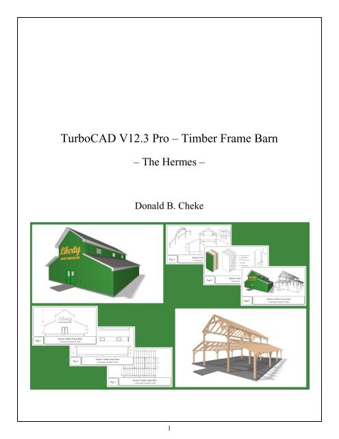
<strong>TurboCAD</strong> <strong>V12.3</strong> <strong>Pro</strong> – <strong>Timber</strong> <strong>Frame</strong> <strong>Barn</strong>– The Hermes –Donald B. Cheke1
Copyright © 2006 Donald B. Cheke<strong>TurboCAD</strong> is a registered trademark ofIMSI Design.Published by:Donald B. ChekeSaskatoon, SK CanadaVisit: www.textualcreations.caAll rights reservedNo part of this document may be reproduced, copied, stored on a retrieval system or transmitted in anyform without written permission from the author. The purchaser may, however, print one copy of thedocument to paper and may make one backup copy of the downloaded material for personal use only.Limitation of LiabilityWhile every effort has been taken in the preparation and the writing of this document the author assumesno responsibility for errors and/or omissions nor for the uses of the material and the decisions based onsuch use. No warranties are made, express or implied with regard to either the contents of the document,its merchant ability or fitness for a particular purpose. The author should not be liable for direct, indirect,special, incidental or consequential damages arising out of the use or inability to use the contents of thisdocument.Special NoteAll of the work presented within this tutorial is based on <strong>TurboCAD</strong> <strong>V12.3</strong> <strong>Pro</strong>. Although users ofprevious versions are welcome to try the tutorial it cannot be stated what results will be achieved. Manychanges, some subtle and others not so subtle, are made with each program revision. Although manysteps and directions would be generic some may not be. The same can be said for tools betweenversions. Older versions may not have the same tools as <strong>V12.3</strong> <strong>Pro</strong> and if the same tools are availablethe tools themselves may have been revised and hence, work in a different manner than they previouslydid.The author would like to extend a big thank you to Vermont <strong>Timber</strong> Worksfor allowing the use of the Hermes <strong>Barn</strong> material on their web site for thistutorial. Having good resources and the cooperation from a real worldbusiness makes it much easier to create tutorials that fit with the realities ofcomputer aided design.Please visit Vermont <strong>Timber</strong> Works on line and have a look around at thegreat work they do.Vermont <strong>Timber</strong> Works http://www.vermonttimberworks.com/36 Fairbanks RoadN. Springfield, Vt. 05150United States2
Table of Contents__________Table of Contents...................................................................................................................................... 3Introduction............................................................................................................................................... 4The Hermes <strong>Barn</strong> – Main <strong>Timber</strong>s ......................................................................................................... 6Setup........................................................................................................................................................... 8Hammer Beam Bent ............................................................................................................................... 18Materials Application – Session 1.......................................................................................................... 19Render Check – A ................................................................................................................................... 23Hammer Beam Bent – Continued A...................................................................................................... 23Image Insertion and Scale...................................................................................................................... 48Hammer Beam Bent – Continued B...................................................................................................... 52Upper Roof Rafters................................................................................................................................. 65Stall Area <strong>Timber</strong>s.................................................................................................................................. 80Wall Panels – SIP – Session 1............................................................................................................... 105Doors / Door Materials ......................................................................................................................... 129Wall Panels – SIP – Session 2............................................................................................................... 138Roof Panels – SIP.................................................................................................................................. 140Soffits and Fascia .................................................................................................................................. 143Shingles .................................................................................................................................................. 153Windows................................................................................................................................................. 160Concrete Slab ........................................................................................................................................ 168Bent – Exploded View........................................................................................................................... 170SIP Panel – Exploded View.................................................................................................................. 193Materials Application – Session 2........................................................................................................ 201Shadow Catcher .................................................................................................................................... 229Named View – Session 1 ....................................................................................................................... 231Render Check – B ................................................................................................................................. 234Saving Rendered Image........................................................................................................................ 235Signage ................................................................................................................................................... 238Named View – Session 2 ....................................................................................................................... 244Paper Space ........................................................................................................................................... 248Printing .................................................................................................................................................. 2953
This tutorial assumes that the beginner has studied the desktop to some degree and can locate most ofthe tools. Since there are endless desktop configurations that can be set up in <strong>TurboCAD</strong> the author hasopted to illustrate the required tools with the V11 user interface and the default toolbars in theirundocked format.This tutorial also utilizes a tool that does not come pre-packed with <strong>TurboCAD</strong>. It is the Copy in Placetool created by David Bell, based on an original macro by Winston Mitchell. It is available as a freedownload on the General Macros page at http://www.bcitool.com/. Please download it and install it asper the instruction that come with the download. It is truly an indispensable tool.The author has borrowed the timber frame definitions from:http://www.timberframedesign.net/timberglossary.html andWordWeb 4.5A Free Version (http://wordweb.info/)Place all of the supplied images in a permanent location on the hard drive of the computer.5
The Hermes <strong>Barn</strong> – Main <strong>Timber</strong>sImages from the Vermont <strong>Timber</strong> Works website.For the timber frame portion of the tutorial the dimensions and design will be based on the informationfound on the Vermont <strong>Timber</strong> Works website. To make following along easier a reader may wish todownload and print some of the barn drawings. If you have a printer that only allows 8½ × 11 (or 14)paper, remember that Adobe Acrobat reader does offer the ability to print only what is in view. Since thePDF files are such good quality zooming in will still provide top notch prints.6
SetupBegin a new drawing in Model Space. If the user has not changed any program preferences the newdrawing should be based on the Normal Imperial default template that comes with the program. If this isnot the one that opens do not worry as the drawing will be changed immediately to better suit thetutorial.Ensure that the <strong>TurboCAD</strong> desktop is set to Isometric SE view.Select Plane by World from the Workplane toolbar.From the Option Menu at the top of the <strong>TurboCAD</strong> desktop select Preference. Uncheck the Use Choiceoption. Click OK to exit the dialogue.Activate the Part Tree. To do so, open the Part Tree palette, select the Part Tree Options icon, adjust thesettings as indicated in the picture below and click OK.So that there is no confusion experienced while following the tutorial please ensure that all 3D entitiesare created as solids (default in <strong>Pro</strong>) and that the following Drawing Setup properties are established.From the Option menu at the top of the <strong>TurboCAD</strong> desktop select Drawing Setup.8
Sometimes it is best to set the Space Units first and then click OK to exit and then reopen the DrawingSetup and complete the rest of the setup, especially if going from Imperial to Metric.Display.Grid.Advanced Grid.Space Units.9
Hammer Beam BentBent: Structural network of timbers or a truss that makes up one cross-sectional piece of the frame.The first bent will be made utilizing, for the most part, 3D components as one might do in the realworld. A single timber will be created, it will have materials assigned to it and this timber will be thebasis for all of the timbers in the drawing.Select the Box tool from the 3D Object toolbar.Place the cursor in the drawing area over one of the grid intersection. Press the G key (G SEKE snap) onthe keyboard to snap the first point of the box (an 8 × 8 × 19' timber) to the grid. Tab into the InspectorBar and enter 8 in the Length and Height fields and 19' in the Width field. Press Enter.Because the drawing Space Units are set to inches anynumber entered without a suffix will be read as inches.Since the timbers are not standard dimensional lumber itwill be assumed that an 8 × 8 inch timber will measure 8 × 8inches and not 7.5 × 7.5 inches as it would with standardlumber. Since the board in this case is 19 feet long the usermust add the foot suffix (any foot suffix can be used ' or ft).Note: If a user only knew the metric measurement it couldbe enter as well, using the metric suffix and <strong>TurboCAD</strong>would perform the conversion.If a reader has not yet noticed there are instructions at the bottom of the <strong>TurboCAD</strong> desktop to help withthe tools.Like so.Press the Space Bar to exit the tool.18
Materials Application – Session 1A wood material will now be applied to the first timber.Double click on the box to open the <strong>Pro</strong>perties dialogue for the selection.Under the 3D tab select Edit Material.Select the Create New Category icon to the right of the current category name field. Enter Wood Wrapsin the New Category dialogue and click OK.Select the Create New Material icon to the right of the current material name field. Enter <strong>Timber</strong> A inthe New Material dialogue and click OK.19
Select the Wireframe tool from the Render toolbar to end the render.Select the knee brace.Press D SEKE and relocate (M SEKE) the reference point to the middle of the corner line where thehammer post and the upper tie meet. In progress below.Right mouse click and select Rubber Stamp from the Local Menu. Move the cursor to the inside cornerwhere the left post and the lower tie meet and M SEKE snap a copy in place. In progress below.Move the cursor to the inside corner where the left post and the girt meet and M SEKE snap a copy inplace. In progress below. Although the plan calls for a straight brace in this and other locations thedecorative one that was originally created will be used in all brace locations.45
Press Esc to exit the Rubber Stamp tool.Press Esc to deselect the selection.Before continuing a new layer will be created and an object will be assigned to it.Open the Design Director palette and left mouse click the Create New icon at the top of the palette.Enter the name 2D in the name field of the Layer dialogue and click OK.The new layer appears on the palette. Left mouse click the eyes icon that corresponds to the 2D layer.This turns off the layer – not visible. Always leave layer 0 visible as the program uses this layer forinternal operations.The author finds that saving most of the various 2D profiles is a good habit to get into. Should a userneed to recreate some 3D object due to problems that are encountered then there is less work involved asthe profiles are still intact.Select the red knee brace profile and then left mouse click the box to the right of the 2D layer name toassign the selection to the layer. A green checkmark appears indicating that this has been done and theobject disappears from the drawing area – since it is turned off.46
Move the cursor in a right downwardly direction for a short distance and then left mouse click to placethe second point of the image box. In progress below.The image appears after the second left click.From the Tools menu at the top of the <strong>TurboCAD</strong> desktop select Raster Image / Image Manager.The image should be highlighted in the image list. If it is not, select it and then select Embed and thenApply and then OK.49
This embeds the image into the drawing. This way if the original image is moved or deleted, or the filemoved off the originating computer, the image will still remain within the drawing.Zoom in on the Bay View decorative end.Select the Rectangle tool from the Line toolbar.Using two left mouse clicks carefully place a narrow rectangle on the dimension lines of the image asindicated in the picture below.Press the Space Bar to exit the tool.Select the narrow rectangle. Note the size in the Size X field (the reader's will be different since adefinite size was not given when inserting the image).Left mouse click into the Size X field and change the number to what it is supposed to be according tothe image.Copy the number in the Scale X field (the reader's will be different than what is in the image below).Press Esc to move out of the Inspector Bar.50
Select the Mirror Copy tool from the Copy toolbar.M SEKE snap the top of the king post to define the first point of the mirroring line. Press and hold theShift key down. Move the cursor upward a short distance and then left mouse click to define the secondpoint of the mirroring line. Release the Shift key. In progress below.Select the 3D Add tool from the Boolean Facet toolbar.To add the two pieces of the upper tie together, first select the left component and then select the rightcomponent to perform the operation. In progress below.Press the Space Bar to exit the tool.The first bent will now be made into a block.Select all the components of the bent.From the Option menu at the top of the <strong>TurboCAD</strong> desktop select Auto-Naming. Under Blocks check<strong>Pro</strong>mpt for name and Insert blocks when creating. Click OK.62
Open the Blocks palette.Left mouse click and hold down the mouse button on the reference point of the selection. Drag theselection onto the Blocks palette and release the mouse button when the move cursor appears.Enter the name First Bent in the Block Name field and click OK.The block is made and one block is placed back in its original location. This is not something that theuser can see happening.Switch to Isometric SE view.With the block still selected, Tab into the Inspector Bar and enter 0 in the X and Y Position fields. PressEnter to move the bent to a common location for all readers.63
Select the new rafter and stall area corner post; they will be mirror copied to the other side of the barn.Select the Mirror Copy tool from the Copy toolbar.M SEKE snap the bottom side of the girt to define the first point of the mirroring line. Press and hold theShift key down. Move the cursor downward a short distance and then left mouse click to define thesecond point of the mirroring line. Release the Shift key. In progress below.Press and hold the Shift key down. Select the copied rafter and stall area corner post to add them to thecurrent selection. Release the Shift key.Switch to Isometric SE view.Select the Linear Copy tool from the Copy toolbar.Tab into the Inspector Bar and enter 0 in the X Step field, 0 in the Y Step field, -18' in the Z Step fieldand 4 in the Sets field. Press Enter.The result.90
Press and hold the Shift key down. Left mouse click the two corner posts to deselect them. Release theShift key.With the two rafters still selected, select the Copy in Place tool from the BCiTool_GM toolbar 1X.With the two rafters still selected, Tab into the Inspector Bar and enter 6 in the Size Y field. Press Enter.At this point the two six inch rafters will be notched.Select the Box tool from the 3D Object toolbar.Select Blue from the color dropdown menu on the <strong>Pro</strong>perty toolbar.V SEKE snap the first point of the box to the bottom left forward vertex on the left front corner stall areapost.Move the cursor to the top right forward vertex of the same post and V SEKE snap the second point ofthe box. In progress below.91
Switch to Right view.Select Plane by Active View from the Workplane toolbar.Select the Mirror Copy tool from the Copy toolbar.M SEKE snap the bottom line of the middle plate to define the first point of the mirroring line. Press andhold the Shift key down. Move the cursor downward a short distance and then left mouse click to definethe second point of the mirroring line. Release the Shift key. In progress below.Select the three central knee braces at bent 2.Select the Mirror Copy tool from the Copy toolbar.M SEKE snap the bottom line of bent 2 to define the first point of the mirroring line. Press and hold theShift key down. Move the cursor downward a short distance and then left mouse click to define thesecond point of the mirroring line. Release the Shift key. In progress below.Select the three central knee braces at bent 3.Select the Mirror Copy tool from the Copy toolbar.M SEKE snap the bottom line of bent 3 to define the first point of the mirroring line. Press and hold theShift key down. Move the cursor downward a short distance and then left mouse click to define thesecond point of the mirroring line. Release the Shift key. In progress below.100
Press Esc to deselect the selection.Switch to Isometric SE view.Turn off all the layers except layer 0.Select the six right knee braces and the six upper knee braces.Tab into the Inspector Bar and enter 3 in the Delta X field. Press Enter to move them so they are flushwith the out side of the posts.Create a new layer caller Knee Braces.101
Doors / Door MaterialsSelect the Door tool from the Architecture toolbar.Right mouse click on the Door tool icon to open the <strong>Pro</strong>perties dialogue.Under the Door Main tab adjust the various settings to reflect those in the image below.Under the Door Dimension tab adjust the various settings to reflect those in the image below.129
Under the Door Materials tab ensure <strong>Frame</strong> is in the Part dropdown menu and then select Paint from theCategory dropdown menu and select Green Gloss from the Material dropdown menu.Select Stop from the Part dropdown menu and then select Paint from the Category dropdown menu andselect Green Gloss from the Material dropdown menu.130
Select Panel from the Part dropdown menu and then select Paint from the Category dropdown menu andselect Green Gloss from the Material dropdown menu. Select Edit Material.Select the Create New Material icon to the right of the current material name field. Enter Forest GreenGloss in the New Material dialogue and click OK.Left mouse click on the color box to open the color menu. Select Forest Green.131
ShinglesThin boxes will now be placed on the left roof panels. These will eventually have shingle imageswrapped to them.Turn on the eight layers identified in the image below.Select the Workplane by Facet tool from the Workplane toolbar.Move the cursor over the top face of the left upper roof panel and when the facet is highlighted leftmouse click to define the new workplane. In progress below.Select the Box tool from the 3D Object toolbar.Select Black from the color dropdown menu on the <strong>Pro</strong>perty toolbar.At the back of the upper roof panel V SEKE snap the first point of the box to the vertex on the top of thefascia as indicated in the picture below.153
Move the cursor to the front top vertex at the peak and V SEKE snap the second point of the box asindicated in the picture below. In progress below.Tab into the Inspector Bar and enter .25 in the Height field. Press Enter.Select the Workplane by Facet tool from the Workplane toolbar.Move the cursor over the top face of the left lower roof panel and when the facet is highlighted leftmouse click to define the new workplane. In progress below.154
Left mouse click the yellow folder icon next to the File name field and locate the supplied file <strong>Barn</strong>Siding.jpg (created by author) and then click Open.Select the Wrapping tab in the window on the left. Change the Scale to 6.Click OK to exit the Material Editor and click OK to exit the <strong>Pro</strong>perties dialogue.Select all the components of both SIP panels and then select the Quality Rendering tool from the Rendertoolbar to perform a render check.When the panels begin to render select Zoom Selection.Press Esc to deselect the selection after the render completes.Like so.208
Shadow CatcherA simple shadow catcher will be placed below the barn to help create a nicer image.Select the Rectangle tool from the Line toolbar.V SEKE snap the first point of the rectangle to the front left lower corner of the floor slab. In progressbelow.After the snap the rectangle will move to the current world workplane at 0.Move the cursor on the diagonal to the back right lower corner of the floor slab and V SEKE snap thesecond point of the rectangle to the back left lower corner of the floor slab. In progress below.After the snap the rectangle will move to the current world workplane at 0.229
Press the Space Bar to exit the tool.Select the red rectangle and then Tab into the Inspector Bar and enter -6 in the Delta Z field. Press Enterto move the rectangle down.With the rectangle still selected, Tab into the Inspector Bar and enter 2 in the X and Y Scale fields. PressEnter.With the rectangle still selected, select the Surface from <strong>Pro</strong>file option from the Solid/Surface toolbar.This will convert the rectangle into a renderable object that materials can be applied to.Open the <strong>Pro</strong>perties dialogue for the selection. Under the 3D tab select Edit Material.Select the Create New Category icon to the right of the current category name field. Enter ShadowCatcher in the New Category dialogue and click OK.Select the Create New Material icon to the right of the current material name field. Enter 33 - Gray 168in the New Material dialogue and click OK.230
In the same fashion that the timber render was saved as a BMP save the exterior render of the barn.Select the Draft Rendering tool from the Render toolbar. Be patient while it changes.After the render has changed to draft, right mouse click on the Draft Rendering tool icon to open theCamera <strong>Pro</strong>perties dialogue. Under the Camera tab, increase the View Angle to 79.641. Click OK.Select Front View.Select the Walk tool from the Walk Through toolbar.Left mouse click in the drawing and hold the mouse button down.Move the cursor upward slowly and move straight into the barn.242
Once just inside, select the Slide tool from the Walk Through toolbar.Left mouse click in the drawing and hold the mouse button down.Move the cursor downward slowly and move down to about standing height.Press Esc to turn off the Walk Through tool.Select the Quality Rendering tool from the Render toolbar.Allow time for the render to occur.Right mouse click on one of the Standard View icons to open the Named View dialogue. Enter InsideFront Doors in the Name field. Click New. Click Close.243