home automation system - an educational prototype - Daaam.com
home automation system - an educational prototype - Daaam.com
home automation system - an educational prototype - Daaam.com

Create successful ePaper yourself
Turn your PDF publications into a flip-book with our unique Google optimized e-Paper software.
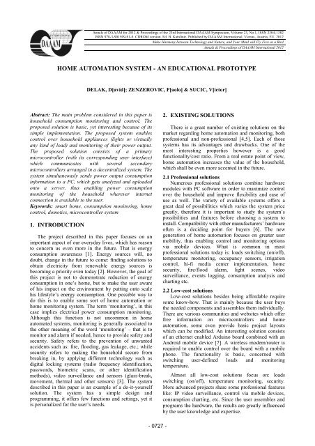
3.2 Schematic <strong>an</strong>d used hardwareFig. 2. Master microcontroller peripheralsThe hardware interaction was simulated with the aidof the simulation package ‘ISIS Proteus7 Professional’,while the program code for master <strong>an</strong>d slave moduleswas developed <strong>an</strong>d <strong>com</strong>piled in the programming suite‘Mikroelektronika mikro Pascal PRO for PIC’. The<strong>com</strong>plete <strong>system</strong> with its hardware <strong>an</strong>d software isdeveloped as <strong>an</strong> open source project. The most recentdata <strong>an</strong>d documentation about this <strong>system</strong> c<strong>an</strong> be foundat: www.cset.<strong>com</strong>.hr/house-power-meter.htmThe hardware layout of the master module is shownin figure 2. The slave module hardware layout is shownin figure 4.The user interface associated to the master moduleconsists of a two lined alph<strong>an</strong>umeric LCD display <strong>an</strong>dfour navigation buttons (‘Up’, ‘Down’, ‘Left’ <strong>an</strong>d‘Right’).Four more buttons (‘B1’, ‘B2’, ‘B3’ <strong>an</strong>d ‘B4’) maybe thought of as part of <strong>an</strong> exp<strong>an</strong>ded navigation whichhelps the user to easily setup button-load configurationsin ‘Program’ mode, <strong>an</strong>d to faster ch<strong>an</strong>ge load states in‘Control’ mode. Those additional buttons are not to beconfused with the ones that are part of each slave module– in spite of the same designation –yet should be thoughtof as <strong>an</strong> addition to the navigation of the main modulewhich enables a more straightforward approach inregards of control <strong>an</strong>d setup of slave modules.An additional ‘Master Off’ button is designed toquickly turn off all loads in the <strong>system</strong>. The mastermodule needs to <strong>com</strong>municate with all slave modules inthe <strong>system</strong>, as well as with a personal <strong>com</strong>puter to enablenetwork monitoring of the household’s powerconsumption.Because data needs to be sent <strong>an</strong>d received frommaster to slave modules, a two-way <strong>com</strong>munication isrequired; however the <strong>com</strong>munication with the personal<strong>com</strong>puter is unidirectional, from the master module to thepersonal <strong>com</strong>puter (because no data needs to be receivedfrom a personal <strong>com</strong>puter in this project). A subcircuitshown in figure 3 <strong>com</strong>posed of digital switches <strong>an</strong>dlogical gates is responsible for switching the connectionbetween master module <strong>an</strong>d slave modules or personal<strong>com</strong>puter <strong>com</strong>munication. This is a simple solution forestablishing two connections via one UART module,although a better alternative would be choosing adifferent microcontroller as a master unit, which featurestwo independent UART modules.All slave modules, with their immediate <strong>com</strong>ponents,share the same hardware schematic. They are <strong>com</strong>posedof four buttons – which (by default) control respectivelyfour loads – <strong>an</strong>d four simulated current probes (eachmeasuring one load’s current). Having the samehardware layout <strong>an</strong>d programming, slave modulesachieve their modular characteristic.Fig. 3. Master microcontroller UART subcircuit switch- 0729 -
3.3 Implementation detailsFig. 4. Slave microcontroller peripheralsSlave modules are identified by their ‘slave ID’number. The slave modules are identical both in thehardware <strong>an</strong>d software. The slave ID number is assignedphysically by grounding or connecting to the powerterminal the pins on PORTB using dip switches: thisresembles a binary number of eight bits whichcorresponds to the slave ID number.This method is very simple <strong>an</strong>d makes m<strong>an</strong>ual‘reprogramming’ of the slave modules possible at <strong>an</strong>ytime without modification to the module’s software.For all the <strong>com</strong>munication of master <strong>an</strong>d slavemodules a serial protocol has been chosen. Using theserial UART protocol is tricky in case of multiple device<strong>com</strong>munication, because of the logic contentions thattake place on a <strong>com</strong>mon <strong>com</strong>munication ch<strong>an</strong>nel. In thiscase logic contentions would take place on the mastermodule’s receive (RX) pin due to the fact one of theslave modules could be tr<strong>an</strong>smitting a message (byte)while all the others are idle. As seen on schematic, thisproblem is solved by adding digital switches on all slavemodules’ tr<strong>an</strong>smit (TX) pin. Logic contentions do nottake place on the master module’s TX pin, so there’s noneed for switches there. In this m<strong>an</strong>ner all slave modulesreceive the same message, but only one of them turns onits switch, thus preventing logic contentions, <strong>an</strong>destablishes a two-way <strong>com</strong>munication with the mastermodule.Essentially the master-slave <strong>com</strong>munication shares aresembl<strong>an</strong>ce with how people <strong>com</strong>municate. Tosuccessfully send a message to <strong>an</strong>y slave module, themaster module needs firstly to address the correct one –this is done by sending the first byte through the<strong>com</strong>munication ch<strong>an</strong>nel, which is always the slave IDnumber (except when pressing the ‘Master Off’ button).Next, in order to tell the slave module what to do, twomore bytes are sent, because <strong>an</strong> unambiguous messagec<strong>an</strong>not be sent with one byte at this point. The secondbyte to be sent through the <strong>com</strong>munication ch<strong>an</strong>nel setsthe chosen slave module in the correct program loop,which basically me<strong>an</strong>s it tells it what to expect as a thirdbyte (except for ‘Power’ mode, load status queries <strong>an</strong>dbutton configuration queries – in those cases a third bytewill not be sent). The second byte sent by the mastermodule will be referred to as a ‘<strong>com</strong>m<strong>an</strong>d ID’ byte.The master-slave <strong>com</strong>munication is conceptualized asfollows:1. master module sends slave ID (e.g. ‘1’)2. respective slave module (e.g. Slave1) waits for<strong>com</strong>m<strong>an</strong>d, other modules ignore <strong>com</strong>munication3. master module sends <strong>com</strong>m<strong>an</strong>d ID (e.g. ‘100’ forControl mode)4. slave module enters respective program loop5. master module sends <strong>com</strong>m<strong>an</strong>d byte (e.g.‘1100xxxx’)6. slave module executes <strong>com</strong>m<strong>an</strong>d (e.g. set loads L4<strong>an</strong>d L3 on, L2 <strong>an</strong>d L1 off)Table 1 shows the <strong>com</strong>m<strong>an</strong>d ID bytes <strong>an</strong>d theirme<strong>an</strong>ing in the <strong>com</strong>munication protocol:Comm<strong>an</strong>d IDCodeDescription100 Control mode101 Power mode102 Program mode110 get load status111 get button configuration255 turn off all loadsTab. 1. Master-slave ‘<strong>com</strong>m<strong>an</strong>d ID’ bytes- 0730 -
When ‘Control’ mode is selected, the master moduleaddresses the desired slave module, sends a code 110 <strong>an</strong>dwaits for a response. When a slave module receives acode 110, it sends to the master module a byte that isessentially a representation of the all the loads statuses.The master module displays the statuses on the LCD as afour-digit binary number – each digit representing oneslave module load status (0 = ‘off’, 1 = ‘on’).During‘Control’ mode the master module inquires the slavemodules for loads status, thus making possible displayingmomentarily <strong>an</strong>y ch<strong>an</strong>ge that takes place remotely (ifslave module buttons are pressed). While slave moduleloads status ch<strong>an</strong>ges are checked periodically, a controlsignal (code 100) with its corresponding message is sentonly if master module buttons (B1 - B4) are pressed. Inthat case the slave module sets its outputs to match thereceived message.When in ‘Program’ mode, the master moduleaddresses the desired slave module <strong>an</strong>d checks its buttonconfiguration (code 111). Editing this configuration isthen possible <strong>an</strong>d is finished when ‘Enter’ button ispressed: the master module addresses again the desiredslave module <strong>an</strong>d issues a program signal (code 102)with its corresponding message. The byte containingslave modules button configuration information is to be<strong>an</strong>alyzed two bits at a time. Having eight bits, a byte issuitable for tr<strong>an</strong>smitting all required information to theslave module: two bits form four <strong>com</strong>binations (fourbuttons) while their placement inside of the byte alsoforms four <strong>com</strong>binations (four loads). Using a similarapproach slave modules have been programmed to storein their EEPROM memory their button configurationdepending on the memory address (1 - 4): the addressdefines the button while the content defines the load.This concept is illustrated in figure 5, <strong>an</strong>d enables thedynamic allocation of load switching <strong>an</strong>d buttons usage.Code 255 is sent to all slave modules whenever the‘Master Off’ button is pressed, <strong>an</strong>d inst<strong>an</strong>tly turns off allloads. Since all loads need to be turned off, addressing allslave modules one at a time would take too much time ina configuration with a great number of slave modules;therefore it is required to address them allsimult<strong>an</strong>eously, <strong>an</strong>d that is the reason why this designhas a virtual limit of 255 slave modules: slave IDnumbers may vary from 0-254 (which makes a total of255 possible slave module identification numbers), while‘255’ c<strong>an</strong>not be a slave ID number, for it is a reservedcode for the ‘Master Off’ feature. For <strong>an</strong>y average userthis limitation on the number of slave modules installedin the <strong>system</strong> surely would not represent a drawback ofthe design. Perhaps <strong>an</strong> industrial application wouldrequire a much bigger number of slave modules, <strong>an</strong>d <strong>an</strong>even greater number for a <strong>system</strong> limit. However thisdesign was never intended for professional/industrialusage, yet personal – <strong>an</strong>d as such proves to be fit.The <strong>system</strong> is projected to carry out powerconsumption readouts. Four current probes are connectedto each slave module, giving a reading from 0-5 Volts.This <strong>an</strong>alog voltage is converted into a 10-bit digitalvalue, giving a resolution of 1024 steps. A 10-bit <strong>an</strong>alogto digital converter gives small conversion errors,allowing fairly accurate power readouts. Supposing amaximum measurable value of 20 Amperes per load, <strong>an</strong>dhaving a const<strong>an</strong>t voltage of 220 Volts, power measuringerrors due to ADC are expected to be less th<strong>an</strong> 5 Watts.The final resulting error might reach a greater value dueto stochastic errors <strong>an</strong>d the fact that all hardware does nothave ideal characteristics. In some br<strong>an</strong>ches of industry a5 Watt measuring error might be of crucial signific<strong>an</strong>ce,as in others would be negligible. Altogether, powermeasuring may be considered as fairly accurate in viewof the project application.3.4 Adv<strong>an</strong>tages <strong>an</strong>d disadv<strong>an</strong>tagesBoth the adv<strong>an</strong>tage <strong>an</strong>d disadv<strong>an</strong>tage of this solutionare its simplicity. This is <strong>an</strong> adv<strong>an</strong>tage for inexpert userswho w<strong>an</strong>t a low-cost solution with basic features. On theother h<strong>an</strong>d, adv<strong>an</strong>ced users will consider professionalsolutions or create a solution of their own to suit theirneeds.The <strong>system</strong> adv<strong>an</strong>tages are: simple design (low number of <strong>com</strong>ponents) quick setup <strong>an</strong>d modularity (easily exp<strong>an</strong>dable) low cost upgradeable design <strong>an</strong>d program (increasablefunctionality <strong>an</strong>d quality)The disadv<strong>an</strong>tages are: basic functionality <strong>com</strong>munication protocol <strong>system</strong> failure in case of master module failureFig. 5. Programming slave microcontroller’s EEPROM with defaultload-button configuration- 0731 -
4. NETWORK MONITORING SOLUTIONThe power output readouts are sent to a PC for further<strong>an</strong>alyses. A serial COM port is used to establish aconnection between master module <strong>an</strong>d personal<strong>com</strong>puter. By implementing a network monitoringsolution, the <strong>system</strong> not only c<strong>an</strong> display powerconsumption information via the user interface, but alsovia <strong>an</strong> internet browser. This way, viewing powerconsumption on a graph in real time is possible frompractically <strong>an</strong>ywhere.4.1 FunctionalityThe <strong>system</strong> has a one-second check interval of allloads power consumption. It is a cumulative, not averagevalue, expressed in kilowatts. Read data is sent viaUART to a COM port.4.2 Implementation detailsSince the <strong>system</strong> is simulated, a pair of virtual COMports has been created. Data is sent from the hardwaresimulation software to one of the virtual ports, <strong>an</strong>d as aconsequence is received by the second virtual port whichis paired. Using Java programming l<strong>an</strong>guage the secondCOM port is defined as <strong>an</strong> input for collecting powerconsumption data sent from the master module. It isessential to setup properly COM <strong>com</strong>munication bymatching various settings (port name, baud rate, databits, stop bits, parity) in the hardware simulationsoftware, serial port simulation software <strong>an</strong>d Java code.The readouts are uploaded to a server so they c<strong>an</strong> beaccessed by the user <strong>an</strong>ytime, from <strong>an</strong>ywhere. In order torealize this, a virtual server is simulated as well. “ApacheFriends XAMPP” software has been used to create avirtual Apache web server. Once again Java is used toestablish a connection with the server through a socket<strong>an</strong>d to send URLencoded information. In order toestablish a connection through a socket some additionalinformation is required, such as: host name, inet address<strong>an</strong>d port. Data is stored by Java <strong>an</strong>d is accessed usingPHP <strong>an</strong>d HTML programming. In order to represent arealtime graph in a browser, Ajax <strong>an</strong>d Javascriptprogramming l<strong>an</strong>guages are implemented.Data c<strong>an</strong> now be visualized on a graph in realtime, asshown in figure 6.Fig. 6. Realtime consumption visualization4.3 Adv<strong>an</strong>tages <strong>an</strong>d disadv<strong>an</strong>tagesThere are both adv<strong>an</strong>tages <strong>an</strong>d disadv<strong>an</strong>tages for thistype of network monitoring solution. One hardwarebaseddisadv<strong>an</strong>tage will be mentioned in this section, forit concerns the network monitoring solution.The adv<strong>an</strong>tages are: functional design with room for improvement data logging <strong>an</strong>d charting access from <strong>an</strong>ywhere in the worldThe disadv<strong>an</strong>tages are: various programming l<strong>an</strong>guages multiple interweaved technologies (Java, PHP,MySQL, Javascript) physical UART switching from module to PC5. CONCLUSION AND FUTURE WORKThe proposed solution is simple, but novice userswould probably be satisfied with its functionality.Fortunately, microcontrollers find use in a wide numberof applications because of their reliability <strong>an</strong>dpossibilities; so improvements of this design, both fromthe hardware <strong>an</strong>d programming point of view, arepossible. What would seem logic as a next step for thisproject, would be to improve existing functions <strong>an</strong>d tooffer new ones, to maximize user-friendliness, <strong>an</strong>d tackleproblems related with the mentioned disadv<strong>an</strong>tages of thedesign. Since hardware <strong>com</strong>munication is of crucialsignific<strong>an</strong>ce, a new <strong>com</strong>munication method should beimplemented in such a way to minimize the possibility of<strong>system</strong> failure due to hardware malfunction or hacking.This me<strong>an</strong>s creating a self-aware <strong>system</strong> which c<strong>an</strong> adaptto minor layout ch<strong>an</strong>ges.6. ACKNOWLEDGEMENTSThe author w<strong>an</strong>ts to express special th<strong>an</strong>ks to theFaculty of Engineering, University of Rijeka <strong>an</strong>d theCroati<strong>an</strong> Society for Educational Technology for itssupport in this project.7. REFERENCES[1] Abdelmohsen, S. & Yi-Luen Do, E. (2008). Energy Puppet: AnAmbient Awareness Interface for Home Energy Consumption,Available from:https://wiki.cc.gatech.edu/design<strong>com</strong>p/images/3/38/SID-Energy-Puppet.pdf Accessed on: 2012-09-19[2] http://www.greenchoices.org/green-living/energy/conventional ,(2009). Accessed on: 2012-09-04[3] Stavridou, V.; Dutertre, B. (1998). From Security to Safety <strong>an</strong>dback, Proceedings of Computer Security, Dependability <strong>an</strong>dAssur<strong>an</strong>ce: from Needs to Solutions, York, UK, 0-7695-0337-3,pp. 182-195[4] http://www.<strong>home</strong>auto.<strong>com</strong>/main.asp , Accessed on:2012-09-04[5] http://www.<strong>home</strong><strong>automation</strong>index.<strong>com</strong> , Accessed on: 2012-09-04[6] http://<strong>home</strong>toys.<strong>com</strong>/emagazine.php?url=/ezine/11.10/calderone15/index.htm , (2011). Accessed on: 2012-09-04[7] http://www.domotic<strong>home</strong>.net , Accessed on: 2012-09-04[8] Ringstaff, C. & Kelley, L. (2002). The Learning Return On OurEducational Technology Investment, Available from:http://dmps.typepad.<strong>com</strong>/tac/learning_return.pdf Accessed on:2012-09-19- 0732 -