fem analysis of pedicle screw-bone interfacefor ... - Daaam.com
fem analysis of pedicle screw-bone interfacefor ... - Daaam.com
fem analysis of pedicle screw-bone interfacefor ... - Daaam.com

You also want an ePaper? Increase the reach of your titles
YUMPU automatically turns print PDFs into web optimized ePapers that Google loves.
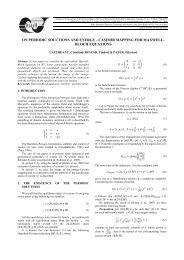
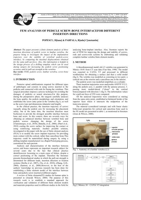
Annals <strong>of</strong> DAAAM for 2011 & Proceedings <strong>of</strong> the 22nd International DAAAM Symposium, Volume 22, No. 1, ISSN 1726-9679ISBN 978-3-901509-83-4, Editor B. Katalinic, Published by DAAAM International, Vienna, Austria, EU, 2011Make Harmony between Technology and Nature, and Your Mind will Fly Free as a BirdAnnals & Proceedings <strong>of</strong> DAAAM International 2011FEM ANALYSIS OF PEDICLE SCREW-BONE INTERFACEFOR DIFFERENTINSERTION DIRECTIONSPOPESCU, D[iana] & PARPALA, R[adu] C[onstantin]Abstract: The paper presents a finite element <strong>analysis</strong> <strong>of</strong> threeinsertion directions <strong>of</strong> <strong>pedicle</strong> <strong>screw</strong> in lumbar vertebra, thepurpose being to investigate the impact <strong>of</strong> the implantationtrajectory over the stability <strong>of</strong> vertebral <strong>pedicle</strong>-<strong>screw</strong>interface, by <strong>com</strong>paring the maximal displacements obtainedfor the same pull-out force. Also, this information is helpful inthe design process <strong>of</strong> a drilling template which can be usedduring surgery for increasing the <strong>pedicle</strong> <strong>screw</strong> positioningaccuracy and its pull-out strength in the vertebra.Key words: FEM, <strong>pedicle</strong> <strong>screw</strong>, lumbar vertebra, <strong>screw</strong>-<strong>bone</strong>interface1. INTRODUCTIONPosterior spinal stabilizationis required for different types<strong>of</strong> pathologies and consists in using <strong>screw</strong>s inserted in the<strong>pedicle</strong>s and connected with rods for fusing the vertebrae. Thissurgical procedure imposes a precise technique for avoiding thedamages <strong>of</strong> <strong>pedicle</strong>s or neural structures.For this purpose,during the preoperative phase, the surgeon carefully analysesthe <strong>bone</strong> quality, the <strong>pedicle</strong> morphology and orientation, andestablishes the <strong>screw</strong> entry point in the vertebra (fig.1), as wellas the <strong>screw</strong> type and dimensions (diameter and length).In the clinical practice, the insertion trajectory <strong>of</strong> <strong>screw</strong>sisusually along the <strong>pedicle</strong> axis for increasing the placementsafety, but in the same time, the insertion direction mustbechoosen to provide the strongest possible interface between<strong>bone</strong> and <strong>screw</strong>. In this context, there are severals ways forobtaining an enhanced interface between vertebral <strong>bone</strong> and<strong>pedicle</strong> <strong>screw</strong>s: changing the design <strong>of</strong> the <strong>screw</strong>(Chatzistergos, et al., 2010), (Batulla, et al., 2006), (Patel et al.,2010) coating the <strong>screw</strong> surface for improving the contact orusing reinforcing materials. Another possible solution,investigated in this paper with the use <strong>of</strong> finite element <strong>analysis</strong>(FEA) is to modify the <strong>screw</strong> implant trajectory for providingmore contact with the cortical, rather than cancellous <strong>bone</strong>.Thistrajectory could be materialised during surgery by using adrilling template manufactured via a Rapid Prototyping process,customized for each pacient.Analysis and characterisation <strong>of</strong> the interface between<strong>screw</strong>s and <strong>bone</strong>s represents an important research subject forseveral years due to the fact that clinical practiceidentifies<strong>screw</strong> loosening as a main cause <strong>of</strong> failure, despite acorrect positioning <strong>of</strong> the implant. Therefore the literaturepresents biomechanical studies in which the pull-out strength isdetermined for different loads, insertion direction or fixationsystems (Sterba et al., 2007), (Xu, et al., 2010), (Zhang, G.H.,2004), (Santoni, et al., 2008).However, to the best <strong>of</strong> theauthors’ knowledge no previous research has been done forestablishing a finite element model <strong>of</strong> the interface between<strong>bone</strong> and <strong>pedicle</strong> <strong>screw</strong> inserted at different angles.A review <strong>of</strong> finite elements(FE) studies for human spine ispresented in (Jones& Wilcox, 2008). The purpose <strong>of</strong> thisresearch work is to establish a standard approach forverification and validation <strong>of</strong> different finite element modelsand materials properties used in different studies in the field foranalysing <strong>bone</strong>-implant interface. Also, literature reports theuse <strong>of</strong> FEM for improving the design and stability <strong>of</strong> <strong>screw</strong>s,rods and <strong>screw</strong>s-rods systems by elaborating and validating<strong>com</strong>plete lumbar vertebra finite element models.2. METHODA threedimensional model <strong>of</strong>a L3 vertebra was generated inMimics 10.01 from CT scan data (Van Sint, 1998). The modelwas exported in CATIA V5 and processed in differentworkbenches for obtaining a surface and then a solid model(fig.2). The vertebra was modelled as consisting in two parts: acortical one at the exterior and a cancellous one in the interior.The <strong>pedicle</strong> <strong>screw</strong> was modelled simplified, as a cylinder.Three insertion trajectories were analyzedin ANSYS V12:1.along the <strong>pedicle</strong> axis; 2. parallel with the spinous process; 3.passing more medial-lateral (“closer” to the cortical<strong>bone</strong>)<strong>com</strong>pared with direction 1 (fig.3). The deformation valuesfor a pull-out force <strong>of</strong> 25N were <strong>com</strong>pared.All the analysed trajectories were considered as startingfrom the same entry point, established at thelateral border <strong>of</strong> thesuperior facet where it intersects the midportion <strong>of</strong> thetransverse process.The material (considered isotropic and with linear elasticbehaviour) properties for cortical and cancelous <strong>bone</strong> used inthe FE model are presented in table 1, as mentioned in literature(Jones & Wilcox, 2008).Fig. 1. Anatomy <strong>of</strong> a lumbar vertebra (L3)Fig.2. Mimics 10 – CATIA V5 integration
Fig.3. Mesh <strong>of</strong> the <strong>bone</strong> and <strong>screw</strong> – ANSYS V12Young Modulus Poisson ratio(MPa)Cortical <strong>bone</strong> 780 0.3Cancellous Bone 100 0.2Screw 100000 0.3Vertebral arch 1000 0.45Articular process 1000 0.45Tab. 1. Material properties for <strong>bone</strong> and <strong>pedicle</strong> <strong>screw</strong>Fig. 5. Total deformation – trajectory 1Trajectory 1 Trajectory 2 Trajectory 3Maximaldeformation3,5871∙10 -7 m 2,042∙10 -7 m 2,242∙10 -7 mEquivalentvon Miss 4,4411 MPa 3,362 MPa 3,3155MPastressTab. 2. Results <strong>of</strong> FE <strong>analysis</strong> for three insertion trajectories5. ACKNOWLEDGEMENTSThe work has been co-funded by the Sectoral OperationalProgramme Human Resources Development 2007-2013 <strong>of</strong> theRomanian Ministry <strong>of</strong> Labour, Family and Social Protectionthrough the Financial Agreement POSDRU/89/1.5/S/62557.6. REFERENCESFig. 4. Insertion trajectories for the <strong>pedicle</strong> <strong>screw</strong>3. RESULTSAnalysing the total deformation and equivalent von Missstressobtained in FEA (an example is presented in figure 3), thebest insertion trajectory is parallel to the spinous process (table2). These results are confirmed by the biomechanical testspresented in (Sterba et al., 2007) and (Santoni et al., 2008).The explanation <strong>of</strong> this result is that the <strong>screw</strong>’s thread, inthis position, <strong>com</strong>es in contact with a larger part <strong>of</strong> the cortical<strong>bone</strong> – with better material properties <strong>com</strong>pared to cancellous<strong>bone</strong>, this way improving the fixation strength. Due to the factthat this path is practically difficult to achieve, a drill guide,customized for each patient and manufactured using a RapidManufacturing process, could be a solution.4. DISCUSSION AND CONCLUSIONSThe purpose <strong>of</strong> the research was to find a way to improvethe longevity and stability <strong>of</strong> vertebral <strong>pedicle</strong>-<strong>screw</strong> interface.To the best <strong>of</strong> the authors’ knowledge no previous research hasbeen done for finite element modeling <strong>of</strong> the interface between<strong>bone</strong> and <strong>pedicle</strong> <strong>screw</strong> inserted at different angles, althoughbiomechanical tests were performed in this sense.The <strong>com</strong>plexity <strong>of</strong> the problem resides in the difficulty toestablish material properties or the correct boundary conditionsconsidering the great variation between individuals. Therefore,further <strong>analysis</strong> will consider not only the use <strong>of</strong> a standard<strong>screw</strong> model, but also a better assessment <strong>of</strong> <strong>bone</strong> mechanicalproperties considering the new approach in which estimations<strong>of</strong> material properties are assigned based on the relationbetween Hounsfield units, <strong>bone</strong> mineral density (informationavailable by quantitative <strong>com</strong>puter tomography - QCT) andelastic modulus (Jovanovici, J.D., et al., 2010).Battula, S., et al. (2006). Experimental evaluation <strong>of</strong> theholding power/stiffness <strong>of</strong> the self-tapping <strong>bone</strong> <strong>screw</strong>s innormal and osteoporotic <strong>bone</strong> material. ClinicalBiomechanics, 2:533–537Chatzistergos, P.E., et al. (2010). A parametric study <strong>of</strong>cylindrical <strong>pedicle</strong> <strong>screw</strong> desgin implications on the pulloutperformance using an experimentally validated finiteelementmodel, Medical Engineering&Physics, 32:145-154Inceoglu, S., et al. (2007).Cortex <strong>of</strong> the <strong>pedicle</strong> <strong>of</strong> the vertebralarch. Part II: Microstructure, J Neurosurg Spine 7:347–351Jones, A., Wilcox, R. (2008), Finite element <strong>analysis</strong> <strong>of</strong> thespine: Towards a framework <strong>of</strong> verification, validation andsensitivity <strong>analysis</strong>, Medical Engineering&Physics, 30:1287–1304Jovanovici, J.D. et al. 2010. Finite element modeling <strong>of</strong> thevertebra with geometry and material properties retrievefrom CT-scan data, FactaUniversitatis, Series: MechanicalEngineering. 8(1):19 – 26Patel, P., et al. (2010). The effect <strong>of</strong> <strong>screw</strong> insertion angle andthread type on the pull-out strength <strong>of</strong> <strong>bone</strong> <strong>screw</strong>s innormal and osteoporotic cancellous <strong>bone</strong> models, MedicalEngineering&Physics, 32(8):822-828Santoni, B.G., et al. (2008). Cortical <strong>bone</strong> trajectory for lumbar<strong>pedicle</strong> <strong>screw</strong>s, The Spine Journal, pp.1-8Sterba, W., et al. (2007). Biomechanical <strong>analysis</strong> <strong>of</strong> different<strong>pedicle</strong> <strong>screw</strong> insertion angles, Clinical Biomechanics,22:385-391Van Sint J. S. (1998). Bone and Join CT-scan data,http://isbweb.org/data/vsj/index.html, The Laboratory <strong>of</strong>Human Anatomy and Embryology, Faculty <strong>of</strong> Medicine,University <strong>of</strong> BrusselsXu, H.G., et al. (2010), Finite element <strong>analysis</strong> <strong>of</strong> the <strong>screw</strong> inpercutaneous axial lumbosacral interbody fusion,Orthopaedic Surgery, Vol.2, 3: 207–210Zhang, G.H. (2004). Investigation <strong>of</strong> fixation <strong>screw</strong> pull-outstrength on human spine, Journal <strong>of</strong> Biomechanics, 37:479–485