
You also want an ePaper? Increase the reach of your titles
YUMPU automatically turns print PDFs into web optimized ePapers that Google loves.
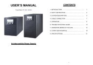
Online <strong>UPS</strong><strong>PowerWalker</strong> VFI 1000T LCD<strong>PowerWalker</strong> VFI 2000T LCD<strong>PowerWalker</strong> VFI 3000T LCD<strong>Manual</strong> (EN)Uninterruptible Power Supply System-1-
CONTENT1. Safety and EMC Instructions .............................................................. 11.1 Installation ......................................................................................... 11.2 Operation .......................................................................................... 21.3 Maintenance, servicing and faults .................................................... 31.4 Transport ........................................................................................... 41.5 Storage ............................................................................................. 41.6 Standards .......................................................................................... 52. Description of Commonly Used Symbols ......................................... 63. Introduction .......................................................................................... 74. Panel Description ................................................................................. 85. Connection and Operation ................................................................ 125.1 Inspection ....................................................................................... 125.2 Connection...................................................................................... 125.3 Battery charge ................................................................................ 145.4 Turn on the <strong>UPS</strong> ............................................................................. 155.5 Test function .................................................................................... 155.6 Turn off the <strong>UPS</strong> ............................................................................. 155.7 Audible alarm mute function ........................................................... 165.8 Operation procedure of external battery for long backup time model(“L” model) ....................................................................................... 166. Operating Mode for All Models ......................................................... 186.1 Line mode ....................................................................................... 186.2 Battery mode .................................................................................. 196.3 Bypass mode .................................................................................. 206.4 NO output mode ............................................................................. 216.5 EPO (Emergency Power Off) ......................................................... 226.6 ECO mode (Economy mode) ......................................................... 226.7 Converter mode .............................................................................. 226.8 Abnormal mode .............................................................................. 23
7. Setting by LCD Module ...................................................................... 248. Trouble Shooting ................................................................................ 279. Maintenance ........................................................................................ 319.1 Operation ........................................................................................ 319.2 Storage ........................................................................................... 319.3 Battery Replace .............................................................................. 3110. Technical Data .................................................................................. 3210.1 Electrical specifications ................................................................ 3210.2 Operating Environment ................................................................ 3310.3 Typical backup time (Typical values at 25°C in minutes:) ................ 3310.4 Dimensions and weights .............................................................. 3311. Communication Port ........................................................................ 3411.1 USB ............................................................................................... 3411.2 RS232 Interface(Option) ............................................................... 3411.3 AS400 Interface (Option) .............................................................. 3412. Software ............................................................................................ 36Appendix: Rear panel ............................................................................ 36
1. Safety and EMC InstructionsPlease read carefully the following user manual and thesafety instructions before installing the unit or using theunit!1.1 Installation★ See installation instructions before connecting to the supply.★ Condensation may occur if the <strong>UPS</strong> is moved directly from a coldto a warm environment. The <strong>UPS</strong> must be absolutely dry beforebeing installed. Please allow an acclimatization time of at leasttwo hours.★ Do not install the <strong>UPS</strong> near water or in damp environment.★ Do not install the <strong>UPS</strong> where it would be exposed to directsunlight or near heat.★ Do not connect appliances or items of equipment which wouldoverload the <strong>UPS</strong> (e.g. laser printers, etc) to the <strong>UPS</strong> output.★ Place cables in such a way that no one can step on or trip overthem.★ Assure to connect with the earth reliably.★ Assure external battery source must be earthed.★ Connect the <strong>UPS</strong> only to an earthed shockproof socket outlet.★ The building wiring socket outlet (shockproof socket outlet) mustbe easily accessible to close to the <strong>UPS</strong>.★ With the installation of the equipment, the sum of the leakagecurrent of the <strong>UPS</strong> and the connected load does not exceed3.5mA.★ Do not block ventilation openings in the <strong>UPS</strong>’s housing. Ensurethe air vents on the front, side and rear of the <strong>UPS</strong> are notblocked. Allow at least 25cm of space on each side.1
2★ <strong>UPS</strong> has provided earthed terminal, in the final installed systemconfiguration, equipotential earth bonding to the external <strong>UPS</strong>battery cabinets.★ An appropriate disconnect device as short-circuit backupprotection should be provided in the building wiring installation.Please see the disconnect device specification in chapter 5.2.★ Equipment the powered more than one source.1.2 Operation★ Do not disconnect the mains cable on the <strong>UPS</strong> or the buildingwiring socket (grounded shockproof socket) during operation asthis would remove the ground to the <strong>UPS</strong> and of all connectedloads.★ The <strong>UPS</strong> features its own, internal current source (batteries). Youmay be electric shock when you touch the <strong>UPS</strong> output sockets oroutput terminal block even if the <strong>UPS</strong> is not connected to thebuilding wiring socket.★ In order to fully disconnect the <strong>UPS</strong>, first press the OFF button toturn off the <strong>UPS</strong>, then disconnect the mains lead.
★ Ensure that no liquid or other foreign objects can enter the <strong>UPS</strong>.★ Do not remove the enclosure. This system is to be serviced byqualified service personnel only.★ Remove the protective panel only after disconnecting the terminalconnections.★ Use No. 12AWG (for 3K/KS output terminal), 90℃ copper wireand 12 lb-in Torque force when connecting to terminal block.★ Use No. 12 AWG (for 3KS input wire), 90℃ copper wire and4.4 lb-in Torque force when connecting to terminal block.1.3 Maintenance, servicing and faults★ The <strong>UPS</strong> operates with hazardous voltages. Repairs may becarried out only by qualified maintenance personnel.★ Caution - risk of electric shock. Even after the unit isdisconnected from the mains power supply (building wiringsocket), components inside the <strong>UPS</strong> are still connected to thebattery which are potentially dangerous.★ Before carrying out any kind of service and/or maintenance,disconnect the batteries. Verify that no current is present and nohazardous voltage exists in the capacitor or BUS capacitorterminals.★ Batteries must be replaced only by qualified personnel.★ Caution - risk of electric shock. The battery circuit is not isolatedfrom the input voltage. Hazardous voltages may occur betweenthe battery terminals and the ground. Verify that no voltage ispresent before servicing!★ Batteries have a high short-circuit current and pose a risk ofshock. Take all precautionary measures specified below andany other measures necessary when working with batteries:- remove all jewellery, wristwatches, rings and other metalobjects3
- use only tools with insulated grips and handles.★ When changing batteries, replace with the same quantity and thesame type of batteries.★ Do not attempt to dispose of batteries by burning them. It couldcause explosion.★ Do not open or destroy batteries. Effluent electrolyte can causeinjury to the skin and eyes. It may be toxic.★ Please replace the fuse only by a fuse of the same type and ofthe same amperage in order to avoid fire hazards.★ Do not dismantle the <strong>UPS</strong>, except the qualified maintenancepersonnel.1.4 Transport★ Please transport the <strong>UPS</strong> only in the original packaging (toprotect against shock and impact).1.5 Storage★ The <strong>UPS</strong> must be stockpiled in the room where it is ventilatedand dry.4
1.6 Standards* SafetyIEC/EN 62040-1* EMIConducted Emission................................:IEC/EN 62040-2Radiated Emission...................................:IEC/EN 62040-2Category C1Category C1Harmonic Current.................................:IEC/EN 61000-3-2Voltage Fluctuation and Flicker............:IEC/EN 61000-3-3*EMSESD......................................................:IEC/EN 61000-4-2 Level 4RS.........................................................:IEC/EN 61000-4-3 Level 3EFT........................................................:IEC/EN 61000-4-4 Level 4SURGE..................................................:IEC/EN 61000-4-5 Level 4CS………………………………….……...:IEC/EN 61000-4-6 Level 3MS………………………………………..: IEC/EN 61000-4-8 Level 3Voltaje Dips………………………...…...: IEC/EN 61000-4-11Low Frequency Signals..........................:IEC/EN 61000-2-25
2. Description of Commonly Used SymbolsSome or all of the following symbols may be used in this manual. It isadvisable to familiarize yourself with them and understand theirmeaning:6
3. IntroductionThis On-Line-Series is an uninterruptible power supply incorporatingdouble-converter technology. It provides perfect protection specificallyfor Novell, Windows NT and UNIX servers.The double-converter principle eliminates all mains power disturbances.A rectifier converts the alternating current from the socket outlet to directcurrent. This direct current charges the batteries and powers theinverter. On the basis of this DC voltage, the inverter generates asinusoidal AC voltage, which permanently supplies the loads.Computers and periphery are thus powered entirely by the mainsvoltage. In the event of power failure, the maintenance-free batteriespower the inverter.This manual covers the <strong>UPS</strong> listed as follows. Please confirm whether itis the model you intend to purchase by performing a visual inspection ofthe Model No. on the rear panel of the <strong>UPS</strong>.Model No. Type Model No. Type<strong>PowerWalker</strong>VFI 1000T LCD<strong>PowerWalker</strong> VFI1000T LCD L<strong>PowerWalker</strong><strong>PowerWalker</strong> VFI ExtendedStandardVFI 2000T LCD2000T LCD L backup time<strong>PowerWalker</strong>VFI 3000T LCD<strong>PowerWalker</strong> VFI3000T LCD L“L” Model: Extended backup time7
4. Panel DescriptionThe Display PanelSwitchON-ButtonOFF-ButtonSelect-ButtonEnter-Button8FunctionTurn on <strong>UPS</strong> system:By pressing the ON-Button “I” the <strong>UPS</strong> system is turnedon.Deactivate acoustic alarm:By pressing this Button an acoustic alarm can bedeactivated in the battery mode.Do the battery test:By pressing this Button the <strong>UPS</strong> can do the battery testin the Line mode or ECO mode or Converter mode.When mains power is normal, the <strong>UPS</strong> system switchesto No output or Bypass mode by pressing OFF-Button“ “, and the inverter is off. At this moment, if Bypass isenabled, then the output sockets are supplied withvoltage via the bypass if the mains power is available.Deactivate acoustic alarm:By pressing this Button an acoustic alarm can bedeactivated in the bypass mode.If the <strong>UPS</strong> system is No output or Bypass mode, theoutput voltage and frequency and Bypassdisable/enable and operating mode could be selected bypressing Select-Button, and confirmed by pressingEnter-Button.
The LCD DisplayDisplayInput InformationOutput InformationFunctionIndicates the input Line voltage value, which couldbe displayed from 0 to 999VacIndicates the frequency value of input Linevoltage, which could be displayed from 0 to 99HzIndicates the input Line voltage is higher than theSPEC range, and the <strong>UPS</strong> would be working inBattery modeIndicates the input Line voltage is lower than theSPEC range, and the <strong>UPS</strong> would be working inBattery modeIndicates the <strong>UPS</strong> output voltage value, whichcould be displayed from 0 to 999VacIndicates the frequency value of the <strong>UPS</strong> outputvoltage, which could be displayed from 0 to 99HzLoad InformationIndicates the load percent in Watt or VA, only themaximum value of them could be displayed from 0to 199%Indicates the load or the <strong>UPS</strong> output is short andthe <strong>UPS</strong> would shut down9
Battery InformationIndicates the load is over the SPEC range(1)Mode/Fault/Warning code InformationInverter operating InformationBypass operating InformationIndicates the battery voltage value, which couldbe displayed from 0 to 999VdcIndicates the battery capacitance percent, whichcould be displayed from 0 to 199%Indicates the battery is over charged, and the<strong>UPS</strong> would be switched to Battery modeIndicates the battery is weak, and the <strong>UPS</strong> wouldshut down soonIndicates the operating mode of the <strong>UPS</strong>, Modecode or Fault code or Warning code could bedisplayed, and the codes are illuminated in detailin the following chapterIndicates the circuit of the inverter is workingIndicates the circuit of Bypass is workingOutput voltage and frequency and Bypass disable/enableselection InformationThe four value of the output voltage could beselected when the <strong>UPS</strong> is in No output or Bypassmode, and only one of them could be active in thesame timeThe two frequency value of the output voltagecould be selected when the <strong>UPS</strong> is in No output orBypass mode, and only one of them could beactive in the same timeBypass disable or enable could be selected whenthe <strong>UPS</strong> is in No output or Bypass mode, and onlyone of them could be active in the same time10
(1) Here would become , , instead when the userdoes operating mode of <strong>UPS</strong> setting.“<strong>UPS</strong>” means the setting of normal inverter mode (Line mode).“ECO” means the setting of economy mode.“CVF” means the setting of converter mode.The detail illustration of the three modes and the operation of thesetting would be presented in the following section.11
5. Connection and OperationThe system may be installed and wired only by qualifiedelectricians in accordance with applicable safety regulations!When installing the electrical wiring, please note the nominalamperage of your incoming feeder.5.1 Inspection:Inspect the packaging carton and its contents for damage. Pleaseinform the transport agency immediately should you find signs ofdamage.Please keep the packaging in a safe place for future use.Note: Please ensure that the incoming feeder is isolated andsecured to prevent it from being switched back on again.5.2 Connection:(1) <strong>UPS</strong> Input ConnectionIf the <strong>UPS</strong> is connected via the power cord, please use a propersocket with protection against electric current, and pay attention tothe capacity of the socket: over 9A for <strong>PowerWalker</strong> VFI 1000TLCD (L), over 17A for <strong>PowerWalker</strong> VFI 2000T LCD (L), over 26Afor <strong>PowerWalker</strong> VFI 3000T LCD (L). If the <strong>UPS</strong> is connected viawires, it is recommended to select the 2.5mm 2 wire, and the“GND” terminal should be grounded first by using the green/yellowwire. The wiring is shown as the following.The <strong>UPS</strong> System has an input breaker on the cabinet. But we stillrecommend users to connect an external breakers or protectivecomponents to the input terminals. It is recommended to select theNFB (Non-Fuse Breaker) instead of the traditional combination kitincluding breaker and fuse.12
When selecting the NFB, the user can refer to below table fordetailed information when installation.Model No.<strong>UPS</strong> INPUT NFBVOLTAGECURRENT<strong>PowerWalker</strong> VFI 1000T LCD (L) 300Vac 10A<strong>PowerWalker</strong> VFI 2000T LCD (L) 300Vac 20A<strong>PowerWalker</strong> VFI 3000T LCD (L) 300Vac 32A(2) <strong>UPS</strong> Output ConnectionThe output of the <strong>UPS</strong> is IEC socket-types. Simply plug the loadpower cord to the output sockets to complete connection. Use onecord for every 5A load.Model No.<strong>PowerWalker</strong> VFI 1000T LCD (L)<strong>PowerWalker</strong> VFI 2000T LCD (L)<strong>PowerWalker</strong> VFI 3000T LCD (L)Output Socket (pcs)3 IEC type6 IEC type4 IEC type+Terminal blockThe wiring configuration is shownas the following procedure:a) Remove the small cover of theterminal blockb) Use 2.5mm 2 wires for wiringconfigurationc) Upon completion of the wiringconfiguration, please checkwhether the wires are securely affixedConnection diagramd) Put the small cover back to the rear panelCaution!Do not connect equipment which would overload the <strong>UPS</strong>system (e.g. laser printers)13
(3) EPO Connection:User can select the polarity of EPO, EPO is Normally open asdefault setting.● Normally openNormally the EPO connector is open on the rear panel. Oncethe connector is closed with a wire, the <strong>UPS</strong> would stop theoutput until the EPO status is disabled.Disable the EPO statusEnable the EPO status● Normally closeNormally the EPO connector is closed with a wire on the rearpanel. Once the connector is open, the <strong>UPS</strong> would stop theoutput until the EPO status is disabledEnable the EPO statusDisable the EPO status5.3 Battery charge:Fully charge the batteries of the <strong>UPS</strong> system by leaving the <strong>UPS</strong>system connected to the mains for 1-2 hours. You may use the <strong>UPS</strong>system directly without charging it but the stored energy time may beshorter than the nominal value specified.14
5.4 Turn on the <strong>UPS</strong>:(1) With utility power connecting:Press “I” button continuously for more than 1 second to turn on the<strong>UPS</strong>, the <strong>UPS</strong> will get into the inverter mode, the LCD screen willindicate the state of the <strong>UPS</strong>.(2) Without utility power connecting:If <strong>UPS</strong> is cold start without utility power connecting, user need topush “I”button twice, first pushing “I” button is for <strong>UPS</strong> to get power,and second pushing “I” button continuously for more than 1second is for <strong>UPS</strong> to turns on, the <strong>UPS</strong> will get into the invertermode.In fact, the two pushing “I” button is to make further sureuser operation for turning on <strong>UPS</strong>, the LCD screen will indicate thestate of the <strong>UPS</strong>.Note: The default setting for bypass mode is no output after<strong>UPS</strong> is connecting utility power and breaker is turned on. Thiscan be configured by monitoring the LCD panel or firmware.5.5 Test function:Test the function of the <strong>UPS</strong> system by pressing the On-Switch “I” formore than 1 second, the <strong>UPS</strong> would detect whether the battery isconnected or the battery is low. And the <strong>UPS</strong> could also do the testautomatically and periodically, the period time could be set by user.5.6 Turn off the <strong>UPS</strong>:(1) In Inverter Mode:Press “ “ button continuously for more than 1 second to turn offthe <strong>UPS</strong>, the <strong>UPS</strong> will get into no output or bypass mode. At thistime, the <strong>UPS</strong> might has output if bypass is enabled. Disconnectthe utility power to turn off the output.(2) In Battery Mode:Press “ “ button continuously for more than 1 second to turn offthe <strong>UPS</strong>, the <strong>UPS</strong> will be turned off completely.15
5.7 Audible alarm mute function:If the alarm is too annoying in battery mode, you may press “I” buttoncontinuously for more than 1 second to clear it. Moreover, the alarmwill be enabled when the battery is low to remind you to shutdown theload soon.If the alarm is too annoying in bypass mode, you may press “ “buttoncontinuously for more than 1 second to clear it. The action doesn’taffect the warning and fault alarm.5.8 Operation procedure of external battery for long backuptime model (“L” model)(1) Use the battery pack with voltage: 36VDC for <strong>PowerWalker</strong> VFI1000T LCD L (3 pcs of 12V batteries), 96VDC for <strong>PowerWalker</strong>VFI 2000T LCD L/ <strong>PowerWalker</strong> VFI 3000T LCD L (8 pcs of 12Vbatteries). Connection of batteries more than or less thanrequired will cause abnormality or permanent damage.(2) One hard wiring type battery terminal on the rear panel is used forconnecting the battery pack.(3) The battery connection procedure is very important. Anyincompliance may result in the risk of electric shock. Therefore,the following steps must be strictly complied with.(4) Make sure the mains input is cut off, if there is a battery breakerthen turn it off first.(5) Remove the small cover of terminal block, prepare the batterycable which should be able to carry the current of >30A for 1000TL, >22A for 2000T L, >33A for 3000T L, the cross section areashould be great than 4 mm 2 for all model. And battery wire color isrecommended as following:+ GND -Red wire Green/Yellow wire Black wire16
(6) The red wire is connected to the "+" terminal of the battery. Theblack wire is connected to the "-" terminal of the battery. (Note:the green/yellow wire is grounded for protection purpose.)(7) Make sure the wires are fasten, install the terminal block cover onthe rear panel of the <strong>UPS</strong>.(8) Connect the <strong>UPS</strong> to the load. Then, turn on the mains switch orconnect the power cord of the <strong>UPS</strong> to utility power supply, thebattery would start to be charged.The Caution!A DC breaker must be connected between the <strong>UPS</strong> andexternal battery.The Caution!The output sockets of the <strong>UPS</strong> system may still be electricallylive even if the power supply system has been disconnected orthe Bypass switch is on “OFF” position.Model No.DC breakerVOLTAGE CURRENT<strong>PowerWalker</strong> VFI 1000T LCD L 48Vac 50A<strong>PowerWalker</strong> VFI 2000T LCD L 125Vdc 40A<strong>PowerWalker</strong> VFI 3000T LCD L 125Vdc 60A17
6. Operating Mode for All ModelsThe different codes could be displayed on the LCD screencorresponding to their own operating modes, and they are illustratedas the following table. At any time, only one normal operating modeor fault mode is presented. But the warning, even several warningscould appear in a certain normal operating mode at one time. Andthe normal operating mode code and the warning code would beshown circularly. Once one fault is come forth, then all previouswarnings would not be shown again but only the fault code ispresented.Normal operating modeNo output mode 0Bypass mode 1Line mode 2Battery mode 3Battery test mode 4ECO mode 5Converter mode 6Code6.1 Line modeThe LCD display in Line mode is shown in the following diagram. Theinformation about the utility power, the battery, the <strong>UPS</strong> output andthe load could be displayed. The “MODE” and “2” code indicate the<strong>UPS</strong> is working in Line mode.18
■ The Line modeIf output overloaded, the load percent is shown and alarm will keeptwice every second. You should get rid of some unnecessary loadsone by one to decrease the loads connected to the <strong>UPS</strong> less than90% of its nominal power capacity.Note: Please follow the following steps to connect the generator:● Activate the generator and wait until the operation is stable beforesupplying power of the generator to the <strong>UPS</strong> (be sure that the <strong>UPS</strong>is in idle mode). Then turn on the <strong>UPS</strong> according to the start-upprocedure. After the <strong>UPS</strong> is turned on, then the loads can beconnected to the <strong>UPS</strong> one by one.● The power capacity of the AC generator should be at least twice ofthe <strong>UPS</strong> capacity.6.2 Battery modeThe LCD display in battery mode is shown in the following diagram.The information about the utility power, the battery, the <strong>UPS</strong> outputand the load could be displayed. The “MODE” and “3” code indicatethe <strong>UPS</strong> is working in the battery mode.19
(1) When the <strong>UPS</strong> is running in battery mode, the buzzer beeps onceevery 4 seconds. If the “ON” button on the front panel is pressedfor more than 1 second again, the buzzer will stop beeping (insilence mode). Press the “ON” button once again for more than 1second to resume the alarm function.2) If the <strong>UPS</strong> is working in battery mode for the input line voltage ishigher than the SPEC range, the alarm symbol - “H” will be shown;if the <strong>UPS</strong> is working in battery mode for the input line voltage islower than the SPEC range, the alarm symbol - “L” will be shown;if the input line voltage is lost, the alarm symbol - “L” would beshown.■ The Battery mode6.3 Bypass modeThe LCD display in bypass mode is shown in the following diagram.The information about the utility power, the battery, the <strong>UPS</strong> outputand the load could be displayed. The <strong>UPS</strong> will beep once every 2minutes in bypass mode. The “MODE” and “1” code indicate the <strong>UPS</strong>is working in the bypass mode.20
The <strong>UPS</strong> does not have the backup function when it is in bypassmode. The power used by the load is supplied from the utility powervia internal filter.6.4 NO output mode■ The Bypass modeThe LCD display in No output mode is shown in the followingdiagram. The information about the utility power, the battery, the <strong>UPS</strong>output and the load could be displayed. The “0” code indicates the<strong>UPS</strong> is working in the No output mode.■ The No output mode21
6.5 EPO (Emergency Power Off)It is also called RPO (Remote Power Off). On LCD display, the modecode is “0”, the word of “EPO” are presented in the position of outputvoltage.It is a special status in which the <strong>UPS</strong> would shut the output off andalarm. The <strong>UPS</strong> could not be turned off by pressing “OFF” button onthe panel, only after releasing EPO status by turning off the EPOswitch.6.6 ECO mode (Economy mode)It is also called high efficiency mode. In ECO mode, on LCD display,the mode code is “5”.After the <strong>UPS</strong> is turned on, the power used by the load is suppliedfrom the utility power via internal filter while the utility power is innormal range, so the high efficiency could be gained in the ECOmode. Once the mains is loss or abnormal, the <strong>UPS</strong> would transfer tobattery mode and the load is supplied continuously by the battery.1) It could be enabled through the LCD setting or the software(Winpower, etc.).2) It is attention that the transfer time of <strong>UPS</strong> output from ECO modeto battery mode is less than 10ms. But it is still too long for somesensitive load.6.7 Converter modeIn converter mode, on LCD display, the mode code is “6”.The <strong>UPS</strong> would free run with fixed output frequency (50Hz or 60Hz)in converter mode. Once the mains is loss or abnormal, the <strong>UPS</strong>would transfer to battery mode and the load is supplied continuouslyby the battery.221) It could be enabled through the LCD setting or the software(Winpower, etc.).
2) The load should be derating to 60% in converter mode.6.8 Abnormal modeIn abnormal mode such as Bus fault etc., the corresponding faultcode would be shown to indicate the operating mode of the <strong>UPS</strong>.And some warning words could also be shown, for example “short!”would be shown when the load or the <strong>UPS</strong> output is short and the<strong>UPS</strong> is in inverter fault mode.23
7. Setting by LCD ModuleThe output voltage and frequency, and bypass state, and ECO mode, andConverter mode could be set directly through LCD module. The outputvoltage could be set to 208V, 220V, 230V and 240V. The output frequencycould be set to 50Hz and 60Hz. The operating mode of <strong>UPS</strong> could be setbetween the Line mode, ECO mode and Converter mode. The bypassstate could be set to enable and disable. But all the settings could only bedone when the <strong>UPS</strong> is in bypass or no output mode.In bypass or no output mode, pressing the “Select” button on the LCDpanel for more than one second, a flickering black dot would be shownbefore “208V” on the screen. And if pressing the “Select” buttoncontinuously again, the flickering black dot would move to “220V”, next to“230V”, “240V”, “50Hz”, “60Hz”, “Bypass Disable”, “Bypass Enable”,“<strong>UPS</strong>”, “ECO”, “CVF” in turn. (Here “<strong>UPS</strong>” means the normal invertermode, and “<strong>UPS</strong>”, “ECO”, and “CVF” would be presented circularly at theposition of output current) And if pressing the “Enter” button for more thanone second at this time, the flickering black dot would turn to flickerlessand the output voltage or frequency or bypass state or mode state settingwould be modified to the selected value. And if no any pressing on the“Select” or “Enter” button lasting for more than 30 seconds, the flickeringblack dot would disappear.The only one voltage value could be selected in “208V”, “220V”, “230V”,“240V” at any time. The only one frequency value could be selected in“50Hz”, “60Hz” at any time. And the output voltage and frequency wouldbe changed to the corresponding value after the right values are selectedon the LCD panel and the <strong>UPS</strong> is turn on by pressing the “ON” Button.The <strong>UPS</strong> would turn to bypass mode in several seconds after “BypassEnable” is selected, and turn to no output mode in several seconds after“Bypass Disable” is selected. The mode change would be active only afterthe <strong>UPS</strong> is turned on.24
■ Here is a example for changing the output voltage from 220Vac to230Vac through the LCD panel.Step 1: One flickering black dot would appear before“208Vac” after pressing the “Select” button.Step 2: The flickering dot would move to “230Vac” afterpressing the “Select” button two times again.25
Step 3: The dot before “230Vac” would turn to flickerlessafter pressing the “Enter” button.Step 4: The output voltage would be 230Vac after the <strong>UPS</strong> isturned on.26
8. Trouble ShootingIf the <strong>UPS</strong> system does not operate correctly, check the operating status onthe LCD display.Normal operating modeCodeNo output mode 0Bypass mode 1Line mode 2Battery mode 3Battery test mode 4ECO mode 5Converter mode 6WarningCodeSite fail 09Fan fail 10Battery over voltage (over charged) 11Battery low 12Charge fail 13DC-DC temperature high 21Inverter temperature high 24Ambient temperature high 25Line voltage high (OVCD action) 26Battery open 27Overload 2927
FaultCodeBus fault 05Inverter fault 06Overload fault 07Over temperature fault 08Inverter short 14Bus short 28If the <strong>UPS</strong> system does not operate correctly, please attempt to solve theproblem using the table below.Problem Possible cause RemedyNo indication, nowarning tone eventhough system isNo input voltage Check building wiringsocket outlet and inputcable.connected to mainspower supplyDisplay Mode Inverter not Press On-Switch “I”.code ”1” in LCD,even though thepower supply isavailableswitched onDisplay Modecode ”3” in LCD, andaudible alarmsounding every 1beep in every 4secondsEmergency supplyperiod shorter thannominal valueMains powersupply has failed,or Input powerand/or frequencyare out of toleranceBatteries not fullycharged / batteriesdefectSwitching to battery modeautomatically.Check input power sourceand inform dealer ifnecessary.Charge the batteries for atleast5 - 8 hours and then checkcapacity. If the problem stillpersists, consult yourdealer.28
Fan failBattery over voltageBattery lowCharge failDC-DC temperaturehighInverter temperaturehighAmbient temperaturehighLine voltage high(OVCD action)Battery openOverloadSite failFan abnormalBattery is overchargedBattery voltage islowThe charge isbrokenInside temperatureof the <strong>UPS</strong> is toohighInside temperatureof the <strong>UPS</strong> is toohighThe ambienttemperature is toohighInput powervoltage is too highBattery pack is notconnectedcorrectlyOverloadPhase and neutralconductor at inputCheck if the fan is runningSwitching to battery modeautomatically, and after thebattery voltage is normaland the mains is normal, the<strong>UPS</strong> would Switching to linemode automatically again.When audible alarmsounding every second,battery is almost empty.Notify dealer.Check the ventilation of the<strong>UPS</strong>, check the ambienttemperature.Check the ventilation of the<strong>UPS</strong>, check the ambienttemperature.Check the environmentventilation.Switching to battery modeautomatically, and after themains is normal, the <strong>UPS</strong>would Switching to linemode automatically again.Do the battery test toconfirm.Check the battery bank isconnected to the <strong>UPS</strong>.Check the battery breaker isturn on.Check the loads andremove some non-criticalloads.Check whether some loadsare failed.Rotate mains power socketby 180° or connect <strong>UPS</strong>29
EPO activeBus faultInverter faultOver temperaturefaultInverter shortof <strong>UPS</strong> system arereversedEPO function isenabled<strong>UPS</strong> internal fault<strong>UPS</strong> internal faultOver temperatureOutput short circuitsystem.Turn off the EPO switch.Notify dealerNotify dealerBus short <strong>UPS</strong> internal fault Notify dealerCheck the ventilation of the<strong>UPS</strong>, check the ambienttemperature and ventilation.Remove all the loads. Turnoff the <strong>UPS</strong>. Check whetherthe output of <strong>UPS</strong> and loadsis short circuit. Make surethe short circuit is removed,and the <strong>UPS</strong> has no internalfaults before turning onagain.Please have the following information at hand before calling theAfter-Sales Service Department:1. Model number, serial number2. Date on which the problem occurred3. LCD display status, Buzzer alarm status4. Utility power condition, load type and capacity, environmenttemperature, ventilation condition5. The information (battery capacity, quantity) of external battery packif the <strong>UPS</strong> is “L” model6. Other information for complete description of the problem30
9. Maintenance9.1 OperationThe <strong>UPS</strong> system contains no user-serviceable parts. If the batteryservice life (3~5 years at 25°C ambient temperature) has beenexceeded, the batteries must be replaced. In this case please contactyour dealer.9.2 StorageIf the batteries are stored in temperate climatic zones, they should becharged every three months for 1~2 hours. You should shorten thecharging intervals to two months at locations subject to hightemperatures.9.3 Battery ReplaceIf the battery service life has been exceeded, the batteries must bereplaced.Battery replacement should be performed only by qualifiedpersonnel.It recommends to shut off the <strong>UPS</strong> completely before the replacement.If there is a battery breaker then turn it off first. Disconnect the batterycable carefully and make sure no any exposed wires can be touched.Reconnect the new batteries to the <strong>UPS</strong> by following section 5.8.Then turn on the battery breaker and press the ON switch to make the<strong>UPS</strong> do the battery test, check whether the battery information isnormal.31
10. Technical Data10.1 Electrical specificationsModel No.PhaseFrequency<strong>PowerWalker</strong>VFI 1000T LCD(L)INPUT<strong>PowerWalker</strong>VFI 2000T LCD(L)Single(45~55)/(54~66) Hz<strong>PowerWalker</strong>VFI 3000T LCD(L)Current(A) 9A 17A 26AModel No.<strong>PowerWalker</strong>VFI 1000T LCD(L)OUTPUT<strong>PowerWalker</strong>VFI 2000T LCD(L)<strong>PowerWalker</strong>VFI 3000T LCD(L)Power rating 1kVA/0.8kW 2kVA/1.6kW 3kVA/2.4kWVoltageFrequencyWave form200/208/220/230/240×(1 士 2%)VAC50/60±0.2Hz (Battery mode)sinusoidalDerating to 90% when the output voltage is adjusted to 208VACDerating to 80% when the output voltage is adjusted to 200VACModel No.BATTERIES<strong>PowerWalker</strong>VFI 1000TLCD<strong>PowerWalker</strong>VFI 2000TLCD<strong>PowerWalker</strong>VFI 3000TLCDNumber and type 3×12V 7Ah 8×12V 7Ah 8×12V 7Ah32
10.2 Operating EnvironmentAmbient Temperature0 o C to 45 o COperating humidity < 95%AltitudeStorage temperature< 1000m0 o C to 45 o C10.3 Typical backup time (Typical values at 25°C in minutes:)Model No. 100 % Load 50 % Load<strong>PowerWalker</strong> VFI 1000T LCD 5 14<strong>PowerWalker</strong> VFI 2000T LCD 9 21<strong>PowerWalker</strong> VFI 3000T LCD 5 1510.4 Dimensions and weightsModel No.<strong>PowerWalker</strong> VFI1000T LCD<strong>PowerWalker</strong> VFI1000T LCD L<strong>PowerWalker</strong> VFI2000T LCD<strong>PowerWalker</strong> VFI2000T LCD L<strong>PowerWalker</strong> VFI3000T LCD<strong>PowerWalker</strong> VFI3000T LCD LDimensions W×D×H(mm)Net Weight(kg)145×400×220 13145×400×220 7192×460×347 31192×460×347 13192×460×347 31192×460×347 1333
11. Communication PortThe communication port is for the monitoring software. A USB portand an intelligent slot are provided.11.1 USBThe USB port is compliance with USB 1.1 protocol.11.2 RS232 Interface(Option)The following is the pin assignment and description of DB-9connector.Pin # Description I/O2 TXD Output3 RXD Input5 GND Input11.3 AS400 Interface (Option)Except for the communication protocol as mentioned above, thisseries <strong>UPS</strong> has AS400 card (an optional accessory) for AS400communication protocol. Please contact your local distributor fordetails. The following is the pin assignment and description of DB-9connector in AS400 card.Pin # Description I/O Pin # Description I/O1 <strong>UPS</strong> Fail Output 6 Bypass Output2 Summary Alarm Output 7 Battery Low Output3 GND Input 8 <strong>UPS</strong> ON Output4RemoteShutdownInput 9 Line Loss Output5 Common Input34
DB-9 Interface of AS400 communication protocol35
12. Software InstallationWinPower is <strong>UPS</strong> monitoring software, featuring user-friendly interface tomonitor and control your <strong>UPS</strong>. This unique software provides completepower protection for computer system while power failure. With thesoftware users can monitor any <strong>UPS</strong> status on the same LAN.Furthermore, a <strong>UPS</strong> can provide security protection for more than onecomputer on the same LAN at the same time, such as shutting downsystem in security, saving application data and shutting down the <strong>UPS</strong>when power fails.Software Installation on your PC:Connected by USB to a PC or notebook, the Software enables communicationbetween the <strong>UPS</strong> and the computer. The <strong>UPS</strong> software monitors the status of the <strong>UPS</strong>,shuts down the system before the <strong>UPS</strong> is exhausted and can remotely observe the<strong>UPS</strong> via the Network (enabling users to manage their system more effectively). UponAC failure or <strong>UPS</strong> battery low, <strong>UPS</strong> takes all necessary actions without interventionfrom the system administrator. In addition to automatic file saving and systemshut-down functions, it can also send warning messages via pager, e-mail etc.• Use the bundled CD and follow the on-screen instructions to install the softwareWinPower.• Enter the following serial No. to install software: 511C1-01220-0100-478DF2A• After the software is successfully installed, the communication with <strong>UPS</strong> hasbeen established and an green icon will appear in the system tray.• Double-click the icon to use the monitor software (as above).• You can schedule <strong>UPS</strong> shutdown/start-up and monitor <strong>UPS</strong> status through PC.• Detail instructions please refer to the e-manual in the software.Check www.powerwalker.com/winpower.html from time to time to get the latestversion of monitoring software.36
Appendix: Rear panel<strong>PowerWalker</strong> VFI 1000T LCD<strong>PowerWalker</strong> VFI 1000T LCD L37
<strong>PowerWalker</strong> VFI 2000T LCD<strong>PowerWalker</strong> VFI 2000T LCD L38
<strong>PowerWalker</strong> VFI 3000T LCD<strong>PowerWalker</strong> VFI 3000T LCD L39
40614-