6400-09 Soil CO2 Flux Chamber
6400-09 Soil CO2 Flux Chamber
6400-09 Soil CO2 Flux Chamber

You also want an ePaper? Increase the reach of your titles
YUMPU automatically turns print PDFs into web optimized ePapers that Google loves.
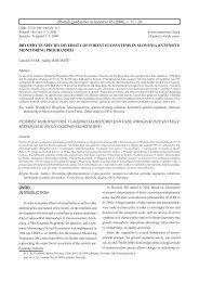
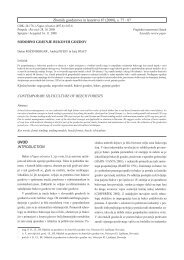
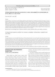
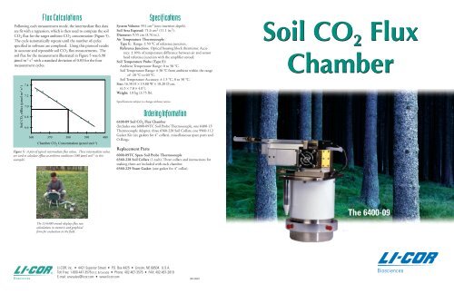
<strong>Flux</strong> Calculatio nsFollowing each measurement mode, the intermediate flux dataare fit with a regression, which is then used to compute the soilCO 2 flux for the target ambient CO 2 concentration (Figure 5).The cycle automatically repeats until the number of cyclesspecified in software are completed. Using this protocol resultsin accurate and repeatable soil CO 2 flux measurements. Thesoil flux for the measurement illustrated in Figure 5 was 6.98µmol m -2 s -1 with a standard deviation of 0.03 for the fourmeasurement cycles.<strong>Soil</strong> CO 2ef f lux (µmol m -2 s -1 )7.47.27.06.86.6Phaseolus vulgaris L.360 370 380 390 400<strong>Chamber</strong> CO 2Concentration (µmol mol -1 )Figure 5. A plot of typical intermediate flux values. These intermediate valuesare used to calculate efflux at ambient conditions (380 µmol mol -1 in thisexample).µSp ecificatio nsSystem Volume: 991 cm 3 (zero insertion depth).<strong>Soil</strong> Area Exposed: 71.6 cm 2 (11.1 in. 2 ).Diameter: 9.55 cm (3.76 in.).Air Temperature Thermocouple:Type E: Range: ± 50 °C of reference junction.Reference Junction: Optical housing block thermistor. Accuracy:± 10% of temperature difference between air and sensorhead reference junction with the amplifier zeroed.<strong>Soil</strong> Temperature Probe (Type E):Ambient Temperature Range: 0 to 50 °C.<strong>Soil</strong> Temperature Range: ± 30 °C from ambient within the rangeof -20 °C to 60 °C.<strong>Soil</strong> Temperature Accuracy: ± 1.5 °C, 0 to 50 °C.Size: 16.50 H × 19.80 W × 10.20 D cm.(6.5 × 7.8 × 4.0").Weight: 1.8 kg (3.75 lb).Specifications subject to change without notice.Orderin g Informatio n<strong>6400</strong>-<strong>09</strong> <strong>Soil</strong> CO 2 <strong>Flux</strong> <strong>Chamber</strong>(Includes one 6000-<strong>09</strong>TC <strong>Soil</strong> Probe Thermocouple, one <strong>6400</strong>-13Thermocouple Adapter, three 6560-228 <strong>Soil</strong> Collars, one 9960-112Gasket Kit (six gaskets for 4" collars), miscellaneous spare parts andO-Rings.Replacement Parts6000-<strong>09</strong>TC Spare <strong>Soil</strong> Probe Thermocouple6560-228 <strong>Soil</strong> Collars (1 each). Three collars and instructions formaking them are included with each chamber.6560-229 Foam Gasket (one gasket for 4" collar).<strong>Soil</strong> CO <strong>Flux</strong>2 <strong>Chamber</strong>The LI-<strong>6400</strong> console displays flux ratecalculations in numeric and graphicalform for evaluation in the field.The <strong>6400</strong>-<strong>09</strong>®LI-COR, inc. • 4421 Superior Street • P.O. Box 4425 • Lincoln, NE 68504. U.S.A.Toll Free: 1-800-447-3576 (U.S. & Canada) • Phone: 402-467-3576 • FAX: 402-467-2819E-mail: envsales@licor.com • www.licor.com980-06607
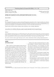
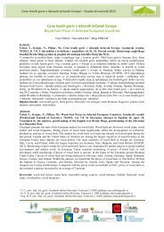
# $ % ^ & * ( ) _2 3 4 5 6 7 8 9 0 -~{ }Q|[ ]AL: " \; '< > ?Z. /ctrlshiftspaceescapeAccurate <strong>Soil</strong> CO 2 <strong>Flux</strong> MeasurementsAccurately measuring soil CO 2 flux can be challenging, evenunder the best of conditions. Factors that influence the soilCO 2 flux rate include chamber pressure, method of mixingthe chamber air, chamber CO 2 concentration, and dilutioneffects of water vapor. LI-COR understands these challenges.For more than a decade we have been perfecting the scienceof measuring soil CO 2 flux using chamber methods. The<strong>6400</strong>-<strong>09</strong> <strong>Soil</strong> CO 2 <strong>Flux</strong> <strong>Chamber</strong> and the LI-<strong>6400</strong> PortablePhotosynthesis System combine to create the best systemavailable for measuring soil CO 2 flux.Effects of Ch a m b er CO 2 Co ncent ratio nThe movement of CO 2 out of the soil is primarily in responseto the concentration gradient between the soil and the ambientatmosphere. <strong>Chamber</strong> CO 2 concentration should not beallowed to build up too far above ambient CO 2 concentration,or the flux will be underestimated. In the LI-<strong>6400</strong>, the chamberconcentration is automatically scrubbed to just below anambient target, and then measured as it rises to slightly aboveambient. This protocol maintains the CO 2 concentrationgradient to within a few ppm of the natural, undisturbed value(Figures 2 and 4).Effects of Pressure<strong>Soil</strong> CO 2 concentration may be many times greater thanambient CO 2 concentration. In addition, soil is a porousmedium, so movement of air into or out of soil, which can becaused by extremely small pressure differentials, can greatlyenhance or suppress soil flux. The <strong>6400</strong>-<strong>09</strong> <strong>Soil</strong> CO 2 <strong>Flux</strong><strong>Chamber</strong> employs a pressure equilibration tube that eliminatesthe development of pressure differentials and at the same timeavoids chamber leaks.Th o ro u g h Mixin gAir in the chamber headspace must be thoroughly mixed inorder to correctly sample the chamber CO 2 concentration.However, mixing must be achieved without causing localizedpressure gradients. The <strong>6400</strong>-<strong>09</strong> uses a fan to push airthrough a perforated manifold to distribute and thoroughlymix the air in the chamber without developing localizedpressure gradients or ventilating the soil surface (Figure 3).Dilutio n Co rrectio nsWhen a closed chamber is placed on a moist soil surface,water vapor concentration in the air increases, causing aproportionate decrease in the air CO 2 partial pressure. Thismay underestimate the CO 2 flux. The need for a dilutioncorrection is especially acute if the rate of increase of humidity islarge in comparison to the rate of increase of CO 2 concentration.This happens with wet soils on dry sunny days, when chamber airtemperature and water vapor rise rapidly. The LI-<strong>6400</strong> measuresthe rate of increase of water vapor at the same time it measuresCO 2 , and automatically applies a dilution correction. This resultsin consistently accurate data.<strong>CO2</strong> flux (µmol/m 2 /s)Figure 1. The CO 2 and H 2 O analyzers in the LI-<strong>6400</strong> sensor head areconnected directly to the soil chamber for fast response.65.554.543.532.5◆◆◆ ◆◆◆◆ ◆Ambient◆ ◆◆◆ ◆◆◆ ◆ ◆ ◆◆◆◆◆◆◆ ◆◆ ◆ ◆◆ ◆20 100 200 300 400 500 600 700 800<strong>Chamber</strong> CO 2 (ppm)Figure 2. <strong>Soil</strong> CO 2 flux dependency on chamber CO 2 concentration.Sa mplin g Aut o m atio nDue to the natural spatial heterogeneity of soil, CO 2 flux measurementsrequire extensive sampling. The LI-<strong>6400</strong> introduces a newlevel of sampling repeatability and accuracy that can easily beachieved with the LI-<strong>6400</strong>'s unique software and hardware automationcontrols.OPEN Softw a reSwitching from photosynthesis to soil CO 2 flux measurements iseasy with the LI-<strong>6400</strong>'s OPEN software. You can quickly configureOPEN for any LI-<strong>6400</strong> accessory by simply picking the chamberaccessory from a list.Four parameters are entered from the LI-<strong>6400</strong> keypad to controlthe automatic measurement:1. Ambient CO 2 concentration (380 µmol mol -1 , in the example inFigure 4).2. The CO 2 change that determines the upper and lower set points(∆CO 2 = ± 5 µmol mol -1 from ambient in Figure 4).3. Depth of the chamber in the soil (or above the soil, if usingcollars).4. Number of measurement cycles.shift X C V B N M ,enter enterS D FG H J K! @1W E R T Y U I O P+=AUXILIARYIRGAO lPlumbing Circuit forCO 2 Scrub OperationCHAMBERREFINLETRS-232SAMPLELI-<strong>6400</strong> SensorHeadPressure Relief FittingGas AnalyzerMixing FanAnalyzer Inlet DuctAnalyzer Outlet DuctPressure ReliefVent TubeManifold (CO 2 Scrub)Manifold (Analyzer Outlet)Figure 3. Schematic showing path of air flow between <strong>6400</strong>-<strong>09</strong> and LI-<strong>6400</strong> console.A fan pushes air through a perforated manifold to thoroughly mix the air.Measurin g Ambient CO 2Before starting a series of measurements, ambient CO 2 ismeasured by laying the soil chamber on its side on the soilsurface, near the location where the chamber will be inserted.Mounting the <strong>Chamber</strong><strong>Chamber</strong> handles (Figure 1) make it easy to press the <strong>6400</strong>-<strong>09</strong> into the soil or to slip it into a soil collar already in thesoil. The preferred method, however, is to use soil collars,which makes repeated sampling easier and also preventsdisturbing of the soil.Aut o mat ed Cyclin g Prot ocolThe measurement protocol is fully automated. Each time thechamber is placed at a new location, simply press the "Start"function key and a new measurement cycle is triggered.Drawdown ModeThe LI-<strong>6400</strong> enters drawdown mode after the "Start" key ispressed. Air is pumped from the chamber through the sodalime CO 2 scrubber and back into the chamber. The systemsoftware automatically stops the pump and enters measurementmode after the CO 2 concentration drops to just below the setpoint (Figure 4).<strong>Chamber</strong> CO 2Concentration (µmol mol -1 )395390385380375370Measurement ModeDrawdown Mode1 2 3 4Time (minutes)Figure 4. Data from a measurement with four cycles.Measurement ModeDuring measurement, the CO 2 concentration of the chamberair rises from the low set point, passing through the targetambient CO 2 concentration, to the high set point. Every twoto three seconds, a flux is computed based on a running averageof the rate of change of CO 2 concentration with time.