gas actuated relays for oil filled transformers en 50216-2 - maxsteel
gas actuated relays for oil filled transformers en 50216-2 - maxsteel
gas actuated relays for oil filled transformers en 50216-2 - maxsteel

You also want an ePaper? Increase the reach of your titles
YUMPU automatically turns print PDFs into web optimized ePapers that Google loves.
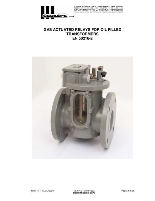
GAS ACTUATED RELAYS FOR OIL FILLEDTRANSFORMERSEN <strong>50216</strong>-2Nome file : RELE EN<strong>50216</strong> REV 04 DTD 23/04/2007 Pagina 1 di 22UNCONTROLLED COPY
1. G<strong>en</strong>eral Features1.1 CharacteristicsThe <strong>gas</strong>-<strong>actuated</strong> protective relay is designed to detect faults as well as tominimise the propagation of any damage, which might occur within <strong>oil</strong>-<strong>filled</strong>trans<strong>for</strong>mers.The relay is there<strong>for</strong>e particularly effective in case of:- short-circuited core laminations- brok<strong>en</strong>-down core bolt insulation- overheating of some part of the windings- bad contacts- short circuits betwe<strong>en</strong> phases, turns- earth faults- puncture of bushing insulators inside tankFurthermore the relay can prev<strong>en</strong>t the developm<strong>en</strong>t of conditions leading to afault in the trans<strong>for</strong>mer, such as the falling of the <strong>oil</strong> level due to leaks, or thep<strong>en</strong>etration of air as a result of defects in the <strong>oil</strong> circulating system.The adoption of other <strong>for</strong>ms of protection does not there<strong>for</strong>e exclude the use ofthe <strong>gas</strong>-<strong>actuated</strong> Buchholz relay, as this device is the only means of detectingincipi<strong>en</strong>t faults, which if unnoticed, can cause heavy failures.1.2 Operating principleThe operation of the Buchholz relay is based upon the fact that every kind offault in an <strong>oil</strong>-<strong>filled</strong> trans<strong>for</strong>mer causes decomposition of the insulating material,be it liquid or solid, due to overheating in the fault zone or to the action of anint<strong>en</strong>se electric field, and g<strong>en</strong>eration of bubble of <strong>gas</strong>.These reach the relay (normally <strong>filled</strong> with <strong>oil</strong>) through the pipe connecting thetrans<strong>for</strong>mer to the conservator where the buchholz relay is mounted2. Special features2.1 Design of active partThe active part of relay is designed in order to permit the free passage of the<strong>oil</strong> flow through the body, not any obstacle (except the flap that detects the <strong>oil</strong>flow rate) such as the floats or any other apparatus is pres<strong>en</strong>t betwe<strong>en</strong> the<strong>en</strong>try and the exit of the <strong>oil</strong> inside the relay.The lower and the upper floats are isolated from flux of <strong>oil</strong> thus unatt<strong>en</strong>dedoperation due to turbul<strong>en</strong>ce of <strong>oil</strong> are avoided.On demand, a special device permit, in case of <strong>oil</strong> surge, to hold the tripcontact in his operated position making possible the relay be resettable onlymanually.2.2 Design of contactsThe <strong>relays</strong> are provided with magnetic switches instead of the traditionalmercury switches in which the high mobility of the mercury makes it necessaryto fit exp<strong>en</strong>sive adjustm<strong>en</strong>ts to avoid unatt<strong>en</strong>ded closing of the contacts andthe consequ<strong>en</strong>t mal-functioning of the relay, wh<strong>en</strong>ever this is subject to severevibrations.Moreover, each contact is operated by 2 magnets displaced in a such way thatmake a constant magnetic field around the contact itself, in this way contact isis not influ<strong>en</strong>ced by external magnetic fields that are pres<strong>en</strong>t on a trans<strong>for</strong>merNome file : RELE EN<strong>50216</strong> REV 04 DTD 23/04/2007 Pagina 2 di 22UNCONTROLLED COPY
3. Operating features3.1 Slight faultsWh<strong>en</strong> a slight or incipi<strong>en</strong>t fault occurs in the trans<strong>for</strong>mers, the small bubbles of<strong>gas</strong>, which pass upwards towards the conservator, are trapped in the relayhousing, thus causing a decrease of the <strong>oil</strong> level inside the relay.As a result, the upper float closes its magnetic switch, thus completing thealarm circuit and operating an external alarm device.3.2 Serious faults3.2.1 Gas g<strong>en</strong>erationWh<strong>en</strong> a serious fault occurs in the trans<strong>for</strong>mer, the <strong>gas</strong> g<strong>en</strong>eration isviol<strong>en</strong>t and causes the <strong>oil</strong> to rush through the connecting pipe to theconservator.In the relay, this <strong>oil</strong> surge impinges on the flap fitted on the lower part(located in front of the hole <strong>for</strong> the <strong>oil</strong> passage) and causes the closingof its magnetic switch, completing the tripping circuit to the circuitbreakerand disconnecting the trans<strong>for</strong>mer.The value of the <strong>oil</strong> speed required to operate the tripping device canbe varied by changing a counterweight fitted on the device itself orchanging its size.3.2.2 Oil leakAn <strong>oil</strong> leak in the trans<strong>for</strong>mer causes the fall down of the <strong>oil</strong> level insidethe relay, thus operating first the alarm (upper) float and th<strong>en</strong> thetripping (lower) float, which will close their own circuits3.2.3 Air inletThe ingress of air into the trans<strong>for</strong>mer, arising from defects in the <strong>oil</strong>circulating system or from other causes, operates the alarm float firstand after the trip contact.4. Construction feature, Finish and Accessories4.1 Construction featuresThe body and the cap of the buchholz relay are made of aluminium alloycasting, <strong>oil</strong> tight weatherproof; the compact design, that means low weight,small sizes, effici<strong>en</strong>cy, is the result of a very long experi<strong>en</strong>ce in manufacturing<strong>relays</strong>. Two flanges on the body permit an easy connection of the relay to thetubes; two large inspection windows made in trogamid (on request made intempered glass), with graduated scale, are fitted on both sides of the relayhousing (on request windows can be provided with sun shield protection).A flat surface on the cap of the relay make it possible, using a spirit level, tomount the relay with the proper inclination4.2 AccessoriesOn the cap of the relay are provided petcock <strong>for</strong> the release of the <strong>gas</strong>, a pushbutton<strong>for</strong> testing the electrical circuits , a small valve <strong>for</strong> pneumatic test(standard on Buchholz size 2” & 3” on request on Buchholz size 1”) and acable box (which is cast integrally to the cap) with 2 cable gland <strong>en</strong>try sizeM25x1.5.On the bottom of the relay is provided a plug <strong>for</strong> draining of <strong>oil</strong>.4.3 FinishIn standard execution, all cast parts are protected by one coat of epoxy primerand one coat of polyurethane paint (total thickness 80 µm), final colour RAL7030 and screws and washer are in stainless steel; the protection degree ofthe device is IP 55. There<strong>for</strong>e the device is suitable <strong>for</strong> outdoor installation intropical climate and with industrial pollution.Nome file : RELE EN<strong>50216</strong> REV 04 DTD 23/04/2007 Pagina 3 di 22UNCONTROLLED COPY
5. Contacts5.1 G<strong>en</strong>eralThe magnetic switches consist of two thin reed contact blades hermeticallysealed inside a glass capsule in an atmosphere of dry inert <strong>gas</strong>.The reeds are made of a ferromagnetic material and are cantilevered into the<strong>en</strong>d of the capsule.The tips of the reeds overlap and are separated by an air gap. The tips,<strong>for</strong>ming the contact surfaces, are coated with a contact material.The switches are operated by a perman<strong>en</strong>t magnet.The operating principle of the magnetic switches is very simple: wh<strong>en</strong> amagnet approaches the switch, the reeds close the circuit; wh<strong>en</strong> the magnetsmoves away from the switch, the contact gets op<strong>en</strong>.5.2 Rated curr<strong>en</strong>tThe rated curr<strong>en</strong>t <strong>for</strong> normally op<strong>en</strong> contacts is 2 A r.m.s. and 1 A <strong>for</strong>changeover contacts;The short time curr<strong>en</strong>t is 10A r.m.s. <strong>for</strong> 30 ms5.3 Breaking and making capacityNormally Op<strong>en</strong> ContactsVoltage MaxCurr<strong>en</strong>tBreakingcapacity24V d.c. to 240V d.c. 2A 250W L/R0,5Change over ContactsVoltage MaxCurr<strong>en</strong>tBreakingcapacity24V d.c. to 240V d.c. 1A 130W L/R0,56. Wiring diagrams6.1 Standard wiring diagramsStandard wiring diagram available are:Type “A” – 2 N/O contacts (1 <strong>for</strong> alarm; 1 <strong>for</strong> trip signalling)Type “L” – 2 change-over contacts (1 <strong>for</strong> alarm; 1 <strong>for</strong> trip signalling)Type “G” – 3 N/O contacts (1 <strong>for</strong> alarm; 2 <strong>for</strong> trip signalling)6.2 Special wiring diagramsSpecial wiring diagram are available on demand on <strong>relays</strong> NB 50 & 80 mm areType S2 - 1 changeover contacts <strong>for</strong> alarm and 1 changeover contact plus 1N/O contact <strong>for</strong> tripType S3 - 1 changeover contacts plus 1 N/O contact <strong>for</strong> alarm and 1changeover contact <strong>for</strong> tripType S4 - 4 contacts N/O; 2 <strong>for</strong> alarm and 2 <strong>for</strong> tripType R - 2 changeover contacts with a device which hold the trip contact inits position in case of <strong>oil</strong> surge operation; manual reset of thecontact by pushing the test button on top of relay (same as TUsystem).Nome file : RELE EN<strong>50216</strong> REV 04 DTD 23/04/2007 Pagina 4 di 22UNCONTROLLED COPY
7. Service conditions7.1 Environm<strong>en</strong>tal conditionsRelays comply with following <strong>en</strong>vironm<strong>en</strong>tal conditions as classified inEN60721-3-4K Climatic conditions 4K2Z Special climatic conditions 4Z2+4Z4+4Z7B Biological conditions 4B1C Chemically active substances 4C2S Mechanically active substances 4S37.2 Special mechanical conditionsOur buchholz relay can withstand to mechanical stresses without unatt<strong>en</strong>dedoperation to the following stresses acc to EN 60721-3-4- stationary sinusoidal vibration class 4M4- non stationary vibration : a vertical shock of 100m/s2, with type 1 spectrum7.3 Protection degreeProtection degree of the terminal box is IP65 acc to EN605297.4 CorrosionThe relay is designed to withstand to corrosion test acc to ASTM B 117 in saltyfog chamber <strong>for</strong> 200h7.5 Pressure and vacuum resistanceThe relay is designed to work continuously with an internal pressure of 50kPabut is capable to withstand an overpressure of 250 kPa <strong>for</strong> 2 min and tovacuum pressure of 2.5 kPa <strong>for</strong> 24h7.6 Insulating liquidThe relay is designed <strong>for</strong> operate with trans<strong>for</strong>mer <strong>oil</strong> with viscosity range from1 mm 2 /s to 1100 mm 2 /s7.7 Working temperatureThe relay is suitable <strong>for</strong> operation in trans<strong>for</strong>mer <strong>oil</strong> over temperature rangefrom minimum minus 25°C to plus 115 °CThe relay is suitable <strong>for</strong> operation in ambi<strong>en</strong>t air temperature range fromminimum minus 45°C to plus 70 °CSpecial execution are available on demand7.8 Mounting positionThe relay is designed to operate properly on a pipe having an inclination fromhorizontal betwe<strong>en</strong> 2 and 5 degrees8. Operational per<strong>for</strong>mance8.1 Operating characteristicsTypical values of the <strong>oil</strong> speed required to operate the tripping elem<strong>en</strong>t undersurge conditions and the volume of accumulated <strong>gas</strong> required to operate thealarm float and trip contact , are:Oil pipe connectioninternal diameterAlarm <strong>for</strong> <strong>gas</strong>accumulation25 mm 150±50 cm³50 mm80 mm200±100 cm³Trip <strong>for</strong> steady <strong>oil</strong>flow100±15 cm/s100±15 cm/s(standard)150±25 cm/s(upon request)200±35 cm/s(upon request)Trip <strong>for</strong> <strong>gas</strong>accumulationafter alarm contactis operated andbe<strong>for</strong>e the <strong>oil</strong>reaches lowestpoint of pipeNome file : RELE EN<strong>50216</strong> REV 04 DTD 23/04/2007 Pagina 5 di 22UNCONTROLLED COPY
9. Installation9.1 MountingThe <strong>gas</strong> <strong>actuated</strong> relay is mounted on the connecting pipe betwe<strong>en</strong> thetrans<strong>for</strong>mer and the conservator.The pipe has to allow the easy flow to the relay of the <strong>gas</strong> arising from faultsinside the trans<strong>for</strong>mer, starting from the highest point on the trans<strong>for</strong>mer coverand must not protrude inside into the trans<strong>for</strong>mer.The pipe should not contain any right-angle elbows. Its diameter shouldcorrespond to the diameter of the hole <strong>for</strong> the passage of <strong>oil</strong> of the relay.The pipe must be arranged to slope upwards towards the conservator at anangle of about 2 to 4 degrees to the horizontal (max 5 degrees).The part of the pipe preceding the relay should be straight <strong>for</strong> a l<strong>en</strong>gth equal toat least five pipe diameters; the part of the pipe leading to the conservatorimmediately adjac<strong>en</strong>t to the relay should be straight <strong>for</strong> a l<strong>en</strong>gth equal to atleast three pipe diameters.A flat surface on the cap of the relay make it possible, using a spirit level, tomount the relay with the proper inclinationThe petcock at the top of the relay must be at a level below the bottom of theconservator.Wh<strong>en</strong> mounting, the arrow <strong>en</strong>graved on the body of the relay must point in thesame direction as the <strong>oil</strong> flow to the conservator.If the trans<strong>for</strong>mer is provided with an explosion v<strong>en</strong>t or similar attachm<strong>en</strong>t, thismust be sealed in such a way that any <strong>gas</strong> liberated by the trans<strong>for</strong>mer doesnot accumulate in the v<strong>en</strong>t, otherwise the operation of the alarm float will bedelayed.9.2 Setting to workOnce the relay has be<strong>en</strong> mounted, unscrew the knurled cap which covers thepush-button <strong>for</strong> checking the circuits and remove from inside it the smallspacer which immobilises the alarm and tripping floats in their lower position,thereby prev<strong>en</strong>ting their movem<strong>en</strong>t during despatch.Op<strong>en</strong> up the <strong>gas</strong> release cock, located on the relay cover, to allow the relay tofill up with <strong>oil</strong>.The filling up and the position of the floats can be se<strong>en</strong> through the inspectionwindows.Wh<strong>en</strong> the relay is <strong>filled</strong> with <strong>oil</strong>, close the <strong>gas</strong> release cock.The electrical circuits must be connected as shown in the diagramaccompanying the relay.9.3 Maint<strong>en</strong>anceThe buchholz relay does not need periodic maint<strong>en</strong>ance; however it isadvisable to check regularly the electric contact and the freely movem<strong>en</strong>t offloat.Nome file : RELE EN<strong>50216</strong> REV 04 DTD 23/04/2007 Pagina 6 di 22UNCONTROLLED COPY
10. Check after actuation of relay10.1 Alarm signalWh<strong>en</strong> the alarm signal is giv<strong>en</strong>, the colour of the <strong>gas</strong> should be observedthrough the inspection-windows.The <strong>gas</strong> may be released or samples can be tak<strong>en</strong> <strong>for</strong> analysis. (If the relay issupplied with our "Buchholz <strong>gas</strong> sampling apparatus RG3, this operation canbe carried out at eye-level).It should be noted that:- whitish <strong>gas</strong> : it is caused by electric arcing in contact with paper, cottonand silk- yellowish <strong>gas</strong> : it is caused by wood and cardboard- greyish <strong>gas</strong> : it is caused by from a breakdown of the magnetic circuit- black <strong>gas</strong> : it is caused by from free arcing in the <strong>oil</strong>Note that there may be air in the trans<strong>for</strong>mer during commissioning or after anoperation of <strong>oil</strong> refillingIn similar cases the alarm is only temporary and should <strong>en</strong>d in a short period oftime.10.2 Trip signalIf the relay disconnects the trans<strong>for</strong>mer, similar checks on the <strong>gas</strong> should bemade to determine the colour and the quantity of <strong>gas</strong> collected.It is always good practice to make a <strong>gas</strong> analysis.In any case, the trans<strong>for</strong>mer should not be immediately re-<strong>en</strong>ergized, as thiswould increase the seriousness of the fault.Note that tripping contact can be <strong>actuated</strong> also by <strong>oil</strong> leak; in that case refill <strong>oil</strong>into conservator after discovered the cause of the <strong>oil</strong> fall be<strong>for</strong>e re-<strong>en</strong>ergizingthe trans<strong>for</strong>mer.11. Test of <strong>gas</strong> on siteIt can be executed only if a <strong>gas</strong> analyser is availableNome file : RELE EN<strong>50216</strong> REV 04 DTD 23/04/2007 Pagina 7 di 22UNCONTROLLED COPY
12. Order instructionsWh<strong>en</strong> ordering a relay it is necessary to indicate (see table)- Type- Size- Wiring diagram- Oil flow rate- Operating conditions- Special requirem<strong>en</strong>tsE B 0 8 0 G 2 7 NT Y P ES I Z EWIRING DIAGRAMOIL FLOW RATEOPERATINGCONDITIONSCTRL CHARLEGENDAEBEEETEU024025050079080N STANDARDX SPECIAL5 LOW TEMPERATURE7 TROPICAL CONDITIONS6 CORROSIVE AMBIENT0 NORMAL AMBIENT2 100 cm/sec3 150 cm/sec4 200 cm/secA2 N/O CONTACTSL2 SPDT CONTACTSG3 N/O CONTACTS2 SPECIAL W.D. S23 SPECIAL W.D. S34 SPECIAL W.D. S42 SPDT contacts withRmanual resettingSEE DRAWINGSRELAY DIN STYLERELAY BRITISH STYLERELAY WITH FLANGE PN6RELAY ITALIAN STYLEExample :To order nr 3 buchholz relay type EB080 wiring diagram G; standard flow rate(100cm/sec); tropical conditions please indicate the following :Nr 1 Buchholz relay type EB080G27NNome file : RELE EN<strong>50216</strong> REV 04 DTD 23/04/2007 Pagina 8 di 22UNCONTROLLED COPY
13. Part d<strong>en</strong>omination of relayPos. Part d<strong>en</strong>ominationMaterial1 Inspection window Trogamid2 Gas release cock Brass3 Push button <strong>for</strong> checking electric circuits Brass4 Terminal box Aluminium alloy5 Cable gland <strong>en</strong>try M25x1.56 Oil flow direction (from tank to conservator)7 Oil drain plug Brass8 Pneumatic test device Brass9 Trip terminals Brass10 Alarm terminals Brass12 Plug M25x1.5 brass13 Window sunshield cover Aluminium15 Earth screw Brass16 Cock <strong>for</strong> air injection test BrassNome file : RELE EN<strong>50216</strong> REV 04 DTD 23/04/2007 Pagina 9 di 22UNCONTROLLED COPY
14. Accessories14.1 Gas sampling device RG3.214.1.1 G<strong>en</strong>eral featuresThe body is made of aluminium alloy casting; in order to check <strong>gas</strong> and<strong>oil</strong> two large inspection windows made in trogamid (on request made intempered glass and with sunshield), are fitted on either side of thecasting.Two petcock complete with hermeto joints are pres<strong>en</strong>t <strong>for</strong> connection torelay and one pneumatic valve <strong>for</strong> test and another petcock draining <strong>oil</strong>complete the apparatus14.1.2 InstallationThe Buchholz <strong>gas</strong> sampling device "RG3" must be fitted on thetrans<strong>for</strong>mer tank, from the ground level, within handy height.A copper tube (size 8 mm OD/ 6 mm ID) must be used to connect the“RG3.2” device, from the cock "12", to the top of the Buchholz relay,cock "R"; <strong>for</strong> connecting the tube to the cocks, special unions "14" shallbe used. If using RG3.3 a second copper tube has to be used <strong>for</strong>connecting cock “T” to cock “15”.Wh<strong>en</strong> the RG3 apparatus has be<strong>en</strong> mounted cocks “R” and “T” have toremain op<strong>en</strong> positionFor filling the device with <strong>oil</strong>, op<strong>en</strong> the cocks "R"; “T”; “15” and "12",op<strong>en</strong> the cock "2" and wait until <strong>oil</strong> has <strong>en</strong>tirely <strong>filled</strong> the «RG3» device,th<strong>en</strong> close cock "2" and “15”; <strong>oil</strong> level inside «RG3» may be controlledthrough the inspection windows located on the two sides.In the normal operating conditions, the <strong>gas</strong> sampling device, theBuchholz relay and the connecting tube betwe<strong>en</strong> them should be <strong>oil</strong><strong>filled</strong>.Nome file : RELE EN<strong>50216</strong> REV 04 DTD 23/04/2007 Pagina 16 di 22UNCONTROLLED COPY
14.1.3 Operating instruction14.1.3.1 Gas sampling from the Buchholz relayOp<strong>en</strong> <strong>oil</strong> drain cock "11" and watch through the «RG3» windows until<strong>gas</strong> is se<strong>en</strong> to have flown into the «RG3» device; th<strong>en</strong> close "11".Now, the <strong>gas</strong>, <strong>for</strong>merly accumulated inside the Buchholz relay due tosome electrical failure inside the trans<strong>for</strong>mer, may be sampled <strong>for</strong>examination or released, by op<strong>en</strong>ing the cock "2".The <strong>gas</strong> should be totally released (i.e. until the «RG3» is completely<strong>filled</strong> again with <strong>oil</strong>) to reset the Buchholz relay in normal operatingconditions; in the case it is necessary to maintain the <strong>gas</strong> inside the«RG3», the shut-off cock "12" and "2" must be closed; cock "2" may bereop<strong>en</strong>ed <strong>for</strong> sampling the <strong>gas</strong> <strong>for</strong> examination, or <strong>for</strong> <strong>gas</strong> release.14.1.3.2 Checking of alarm circuitsCock "12" in op<strong>en</strong> position.Inject air inside «RG3.2» through the bottom valve "8" (after removingthe knurled protecting cap), using a bottle of compressed air or anormal bicycle tyre pump, until the alarm signal (or signals) have be<strong>en</strong>set in operation.To reset the Buchholz relay in normal operating conditions, followabove instructions <strong>for</strong> <strong>gas</strong> sampling and release.14.1.3.3 Checking trip circuitsCock "12" in op<strong>en</strong> position. Inject air inside «RG3.2» through thebottom valve "8" (after removing the knurled protecting cap), using abottle of compressed air or a normal bicycle tyre pump, until the tripsignal (or signals) have be<strong>en</strong> set in operation.To reset the Buchholz relay in normal operating conditions, followabove instructions <strong>for</strong> <strong>gas</strong> sampling and release.If test is executed on Buchholz relay EE type (NB 50 or 80 mm) anRG3.3 is used and trip contact has to be checked as follows:Cock "12" in closed position; cock “15” in op<strong>en</strong> position. Inject air inside«RG3.3» through the bottom valve "8" (after removing the knurledprotecting cap), using a bottle of compressed air or a normal bicycletyre pump, until the trip signal (or signals) have be<strong>en</strong> set in operation.To reset the Buchholz relay in normal operating conditions, followabove instructions <strong>for</strong> <strong>gas</strong> sampling and release.Nome file : RELE EN<strong>50216</strong> REV 04 DTD 23/04/2007 Pagina 17 di 22UNCONTROLLED COPY
14.2 Throttle valves <strong>for</strong> buchholz <strong>relays</strong>This kind of valves, metal to metal sealing, are used on power trans<strong>for</strong>merswith the scope to allow the disconnection of the Buchholz relay from theconservator or from the cover; they are preferred to the conv<strong>en</strong>tional gatevalves <strong>for</strong> their compact overall dim<strong>en</strong>sions in the direction of the <strong>oil</strong> flow.The throttle design and an accurate machining of all the compon<strong>en</strong>tsminimise the <strong>oil</strong> leakage from the throttle in close position, during theoperations of disconnection of the relay with the trans<strong>for</strong>mer <strong>oil</strong> <strong>filled</strong>, it isnecessary to put small containers on the ground to collect the smallquantity of <strong>oil</strong> which flow out from the throttle; once the disconnection isterminated, blind flanges must be put on the throttle valves.All these valves have bodies made in steel ASTM A105 zincplated, paintedand carefully tooled; the design and the execution of the throttle <strong>en</strong>sures agood <strong>oil</strong> proof; once the throttle is closed, the <strong>oil</strong> losses are very small (< 5cc/60” every 25mm of the nominal diameter of the throttle); the drive shaftcan be locked by means of a small padlock in both the close/op<strong>en</strong>positions, which are also indicated by a label; the sealing <strong>gas</strong>kets on thedrive shaft can be easily changed, if necessary, as shown on the sketch inthe drawings.All those valves are supplied with flange NBR sealing <strong>gas</strong>kets.Nome file : RELE EN<strong>50216</strong> REV 04 DTD 23/04/2007 Pagina 18 di 22UNCONTROLLED COPY
14.3 Gas analyser <strong>for</strong> buchholz <strong>relays</strong>If a <strong>gas</strong> analyser kit is available it is possible to have an idea of the causethat g<strong>en</strong>erated the <strong>gas</strong> by checking the precipitate inside the test tube ofthe <strong>gas</strong> analyser.If <strong>gas</strong> is due only to <strong>oil</strong> decomposition, in the test tube 1 a white precipitateis <strong>for</strong>med which, exposed to the light, slowly turns brown.Should, however, in the test tube "2" a black precipitate be <strong>for</strong>med, thismeans that the <strong>gas</strong>es contain decomposition products of solid insulation,such as cotton, paper, wood and the like.In such a case, a c<strong>oil</strong> defici<strong>en</strong>cy has tak<strong>en</strong> place.In the case the Buchholz relay operation is caused by air (first installationinto work, total <strong>oil</strong> refilling, defect in the cooling system) there isn't any<strong>for</strong>mation of precipitate inside the tubes.After the sample of the <strong>gas</strong>es has be<strong>en</strong> drawn, the cock should be closedagain, and the analyser housed in its container.Nome file : RELE EN<strong>50216</strong> REV 04 DTD 23/04/2007 Pagina 19 di 22UNCONTROLLED COPY