ARP2600 - Fundamentals of Music Technology - Cyborgstudio.com
ARP2600 - Fundamentals of Music Technology - Cyborgstudio.com
ARP2600 - Fundamentals of Music Technology - Cyborgstudio.com

Create successful ePaper yourself
Turn your PDF publications into a flip-book with our unique Google optimized e-Paper software.
Secret Society Productions<strong>Fundamentals</strong> <strong>of</strong> <strong>Music</strong> <strong>Technology</strong> Volume One: The ARP 2600 SynthesizerCopyright ©& P 2000 by Samuel Wells Ec<strong>of</strong>f. All Rights Reserved.Except as permitted under the United States Copyright Act <strong>of</strong> 1976, no part <strong>of</strong>this publication may be reproduced or distributed in any form or by any means,or stored in a data base or retrieval system, without the prior written permission<strong>of</strong> the author. If you would like to use excerpts from this book as part <strong>of</strong> a webpage, call me; we’ll talk. :-) The author hereby grants permission to the readerto make copies <strong>of</strong> Appendix Two (patch sheets for the 2600 and ARP sequencer)as needed, as long as they are used for personal purposes, and not for pr<strong>of</strong>it.Typeface: TimesThis book is printed on acid-free paper.CD LICENSING AGREEMENTPermission is hereby granted to create samples from the audio CD included with this book. However, bybreaking the seal on the CD casing, the user agrees to the following terms: The sounds and samples onthis disc are licensed, not sold to you. You may use the sounds and samples found on this disc in a<strong>com</strong>mercial or non-<strong>com</strong>mercial recording without paying any additional license fees. However, you muststrictly adhere to the following crediting guidelines on any music recording that uses material from theenclosed CD:In the written materials ac<strong>com</strong>panying your music release, you must include the following courtesycredits using this wording strictly:ARP 2600 samples courtesy <strong>of</strong> Sam Ec<strong>of</strong>f <strong>of</strong> Secret Society ProductionsUse <strong>of</strong> these sounds is limited to use musical context, and these sounds must not be left exposed wherethey could be easily sampled by a third party. This license <strong>of</strong> free use is granted exclusively to the originalpurchaser <strong>of</strong> this disc and book, and is non-transferrable.Any redistribution <strong>of</strong> this material in any form or by any means is strictly prohibited.®1 1.702 2.033 1.734 3.796 1.678 2.8210 1.3213 1.3315 1.5017 1.3819 1.2221 1.1223 2.1125 1.3127 1.2329 1.3231 1.2233 1.1935 1.1036 1.1037 1.0438 1.0639 1.0840 1.0141 1.342 1.1ii
This book is dedicated to all <strong>of</strong> the people that lovethis wonderful instrument as much as I do; to thepeople who know that the patch isn’t <strong>com</strong>plete untilevery available patch cord has been used.iii
TABLE OF CONTENTSTable <strong>of</strong> Contents............................................................................................................................... ivListing <strong>of</strong> Tracks on CD ....................................................................................................................viHow the CD was Recorded ...............................................................................................................xPrefaces..............................................................................................................................................xiThank You..........................................................................................................................................xiiiAbout the Format <strong>of</strong> this Book.......................................................................................................... xivUNIT ONE: INTRODUCTION AND OSCILLATORSSection One: General Controls.......................................................................................................... 001Experiments........................................................................................................................... 009Review Questions ................................................................................................................. 010Section Two: VCO-1..........................................................................................................................011Experiments........................................................................................................................... 016Review Questions ................................................................................................................. 017Section Three: VCO-2 ...................................................................................................................... 018Experiments........................................................................................................................... 028Review Questions.................................................................................................................. 029Section Four: VCO-3......................................................................................................................... 030Experiments........................................................................................................................... 034Review Questions.................................................................................................................. 035UNIT TWO: MODIFYING THE SIGNALSection Five: Noise Generator........................................................................................................... 036Experiments........................................................................................................................... 040Review Questions.................................................................................................................. 041Section Six: The VCF ....................................................................................................................... 042Experiments........................................................................................................................... 052Review Questions.................................................................................................................. 054Section Seven: ADSR & AR Generators........................................................................................... 055Experiments........................................................................................................................... 060Review Questions.................................................................................................................. 062Section Eight: The VCA.................................................................................................................... 063Experiments........................................................................................................................... 068Review Questions.................................................................................................................. 069iv
TABLE OF CONTENTSUNIT THREE: FINISHING TOUCHESSection Nine: The Mixer Section and Reverberator.......................................................................... 070Experiments........................................................................................................................... 073Review Questions.................................................................................................................. 074Section Ten: The Internal Clock, Electronic Switch, and S/H Circuits............................................. 075Experiments........................................................................................................................... 080Review Questions.................................................................................................................. 081Section Eleven: The Ring Modulator, Preamp and Envelope Follower ........................................... 082Experiments........................................................................................................................... 088Review Questions.................................................................................................................. 090UNIT FOUR: ADDITIONAL MODULESSection Twelve: The Voltage Processors........................................................................................... 091Experiments........................................................................................................................... 095Review Questions.................................................................................................................. 097Section Thirteen: Keyboard Controls................................................................................................ 098Experiments........................................................................................................................... 106Review Questions.................................................................................................................. 108Section Fourteen: Patch Analysis and Diagramming........................................................................ 109Experiments........................................................................................................................... 118Review Questions.................................................................................................................. 118Section Fifteen: Further experiments with the ARP Sequencer.........................................................119Experiments........................................................................................................................... 123Review Questions.................................................................................................................. 124Glossary..............................................................................................................................................125Index.................................................................................................................................................. 136Bibliography.......................................................................................................................................138About the Author................................................................................................................................139APPENDICESAppendix One: Additional Resources for students <strong>of</strong> Electronic <strong>Music</strong>........................................... 140Appendix Two: ARP 2600 + ARP sequencer patch sheets................................................................ 143v
CD TRACK LISTINGTrack Page Note(s) DescriptionSECTION 21 12 C1-C5 VCO-1 Saw Wave, VCO-1 Square Wave2 12 C3 VCO-1 is tuned to VCO-2 (Saw Wave both)3 15 LF VCO-1 in LF mode is gradually increased until it is audible. Sawthen square waveSECTION 34 22 -- VCO-1 FM’d by a saw wave from VCO-2 in LF mode.5 24, 28 -- Sidebands6 25, 28 C1-C5 PWM patch where VCO-1 causes a pulse width sweep.7 18, 28 C1-C5 Saw, Pulse, Sine, Triangle waves from VCO-2.8 28 C3 Pulse width is manually swept.9 28 -- FM patch, all parameters swept one by one.10 28, 106 C1-C5 FM patch, VCO-2 produces interval leaps with square wave.11 27, 28 C1-C5 Phat Tuning VCO-1 and 2 with saw waves, the square waves.SECTION 412 31, 34 C1-C5 Double FM modulation. VCO-1 and VCO-2 modulate VCO-313 32, 34 -- Cross FM modulation patch. VCO-2 and VCO-3 modulate eachother in the audio range. Second time deeper modulation than1st.14 32, 34 -- Series modulation. VCO-1 --> VCO-2 --> VCO-3.15 34 C3-C4 All three VCOs tuned in intervals. Major and minor chords oneach white key.SECTION 516 37 C1-C5 Noise Generator FMs VCO-3. Saw Wave timbre. First with littleFM, second time with a lot <strong>of</strong> FM17 39 C1-C5 Noise Generator PWMs VCO-2. First with small modulationdepth, second time with greater modulation depth.18 40 -- Noise Generator’s raw output, noise frequency slider is then swept.SECTION 619 45, 52 C1-C5 Filter sweeps close on a saw wave from VCO-220 46, 52 C1-C5 Resonant filter sweeps close on saw waves from VCO-1 and 221 47 C1-C3 The VCF is made to self-oscillate. Notice how tuning drifts.22 48 C1-C5 All White keys played key tracking on filter disabled. VCO-1, 2,and 3 in phat tuning.vi
CD TRACK LISTINGTrack Page Note(s) Description23 49 C1-C5 Highpass filter sweep (JP-8000) followed by resonant highpassfilter sweep (JP-8000)24 49 --- This track has intentionally been left blank due to an error inprinting in the book.25 52 C3 Filter’s Fc is modulated by VCO-2’s sine output in the audiorange. Sidebands result.26 52 C2. C3, C4 Keyboard CV no longer controls VCO, but still controls Fc.27 52 C1-C5 VCO-1 saw wave (LF) modulates Filter’s Fc while harmonics <strong>of</strong>a saw wave from VCO-2 are accentuated by heavy resonance.Set mod rate as low as possible.SECTION 728 60 C1-C5 ADSR EG FMs VCO-1, 2 and 3 (mixed waves) Only attack stageis used.29 60 C1-C5 Same as track 28, but just decay.30 60 C1-C5 Same as track 28, but just sustain. Sustain level is manuallychanged during this experiment. (Release on gate increased)31 60 C1-C5 Same as track 28, but just release + sustain. Mod depth increased.32 60 --- Noise generator is put through filter, first w/o resonance, thenwith. Percussion sounds are created.33 60 C1-C5 All VCOs in phat tuning, various ADSR settings, with and withoutresonance. VCF controlled by ADSR.34 60 C1-C3 All VCOs in saw wave, then square, just decay set very shortyields a good bass sound. First without resonance, then with.35 61 C1-C3 Same as 34, but with just sustain.36 61 C1-C3 Same as 34, but with just release + a little sustain.37 61 --- AR FMs all three VCOs while ADSR modulates filter Fc.38 61 --- ADSR FMs all three VCOs while AR modulates filter Fc.39 61 C1-C5 Pitch <strong>of</strong> all three VCOs bends up to proper pitch whenever a noteis played.40 61 C1-C5 ADSR generator FMs all three VCOs in different amounts whileAR controls VCF gating.41 61 C1-C5 ADSR generator PWMs VCO-2SECTION 842 64, 68 C3 VCO-2’s saw is gated first by VCF, then by VCA.43 65, 68 C1-C3 All VCO’s gated by VCA, controlled first with Exponential input,then linear input44 66, 68 C1-C5 VCO-2 in LF mode controls VCA gain to create tremolo. VCO-1 and 3 produce square waves, gated by VCF45 66 C3 VCO-2 in LF mode modulates VCA gain quickly and deeplyenough to produce sidebands.vii
CD TRACK LISTINGTrack Page Note(s) Description67 88 C3 A sine wave from VCO-2 is amplified until it is clipped and turnedinto a square wave.68 88 C1 The output <strong>of</strong> a CD player is preamped, then fed to the envelopefollower before going to the FM inputs on the VCOs, the VCF,and finally the VCA.SECTION 1269 92, 95 C scale VCO-1 reacts normally while the keyboard CV going to VCO-2is inverted. Ascending C scale, then short melodic passage.70 92, 95 C1-C5 Inverted envelope FM’s VCOs, modulates Fc, and finally modulatesVCA’s gain, each in turn.71 92, 95 --- VCO-1’s saw wave in the sub-audio range is inverted and used toFM VCO-2.72 94, 96 C1-C5 The keyboard CV is routed through the lag processor with a large99, 106 lag time to produce portamento. Pitch slides from C1 to C5 andback again.73 96 C2 A lagged square wave from VCO-1 in LF mode FMs VCO-2.SECTION 1374 101 C1 + C scale Duophonic patch in which both voices share the VCF for gating.75 101 C1 + C3 C3 is held while C1 is tapped. The lower voice switches fromone oscillator to two, illustrating how unmusical this can be.76 106 C2 Vibrato is created using the keyboard’s LFO. All parameters areswept, including vibrato delay.77 106 C3 Repeat switch causes constant retriggering.78 107 C Scale Trigger switch on single. Scale is played legato up and down.79 107 C scale Trigger switch on multiple. Scale is played legato up and down.80 107 C Scale Trigger switch on multiple, portamento on, time minimum.SECTION 1481 112, 114 --- FM patch illustrated on page 112.82 115, 11 --- FM patch illustrated on page 115.83 117 --- A wild patch with lots <strong>of</strong> feedback, and modulation occurring inthe audio range. The S/H unit samples the VCA’s output.SECTION 1584 119 --- The frequency <strong>of</strong> VCO-1 is swept upwards first with the INI-TIAL FREQUENCY control, then under control <strong>of</strong> the sequencer.The voltage quantizer causes it to ascend in chromatic half steps.85-93 Miscellaneous sequencer patchesix
HOW THE CD WAS RECORDEDThe audio CD which ac<strong>com</strong>panies this book was recorded by connecting the left and right outputs <strong>of</strong>the ARP 2600’s mixer section to a Mackie LM-3204 mixer. The in<strong>com</strong>ing sounds were <strong>com</strong>pressedslightly with a Behringer Composer <strong>com</strong>pressor before being routed to a Digidesign 882 audio interfaceconnected to a Pro Tools|24 system. The ARP 2600 was then recorded into Mark <strong>of</strong> the Unicorn’sDigital Performer 2.61MT hard disk recording s<strong>of</strong>tware running on a Macintosh G3. It was then editedso that each example began and ended in exactly the right spots and was mastered with plugins fromTC Works and MOTU. Other than the aforementioned gentle <strong>com</strong>pression, no effects were applied tothe in<strong>com</strong>ing sounds from the 2600.The 2600 was played part <strong>of</strong> the time from its own keyboard and part <strong>of</strong> the time from a Fatar SL-880mother keyboard and Digital Performer through a Paia MIDI2CV8 converter. Many <strong>of</strong> the melodicsamples were progammed into Digital Performer to insure timing accuracy and consistency. Whilepurists may argue against the use <strong>of</strong> MIDI in controlling an ARP 2600, the author was left with no otherchoice as a capacitor in the keyboard’s control panel went bad only a week before the final recordingsession for the CD, and the repair unfortunately could not be <strong>com</strong>pleted in time for the final recordingsession. (Special thanks to Tim Smith <strong>of</strong> The Audio Clinic who restored the keyboard control panel toworking condition).When melodic patches were recorded (i.e. pitched sounds) an effort was made to make them availableat many different pitches for reader who may wish to sample them. These pitches can then be used tocreate a multisample which yields the highest amount <strong>of</strong> accuracy in sample playback.The samples associated with Section 15, were created using the ARP sequencer rather than DigitalPerformer running through the Paia converter. As a result, some drift is noticable in tuning and timingstability.x
PREFACEto the first editionThis book is the culmination <strong>of</strong> years <strong>of</strong> work and study into the pedagogy <strong>of</strong> music technology, and Ifear it is also just the beginning, as there will always be more to learn about this exciting new field. Ihave little hope <strong>of</strong> these volumes catching on as standard works, as they are highly instrument-specific.However, I feel that they have pedagogic merit, and where all else fails, they could even substitute foran owner’s manual in a pinch.This book is intentionally printed on every other page so that the student may have a convenient placeto take notes, write questions about readings, and record observations during experiments.As with any field that is in its infancy and is still rapidly evolving, it seems that there is no good way togo about writing about music technology. Either a text is so instrument-specific that it be<strong>com</strong>es outdatedvery quickly (within five years or so) or it is so general that it is <strong>of</strong> little merit to the beginningstudent. I have elected to opt for the former path, as I have consistent access to the instruments inquestion. While this is <strong>of</strong> the greatest value to me, it is <strong>of</strong> very little assistance to anyone else who mightbe interested music technology in general.Because I have always taught these lessons in very small groups or as private lessons, I have alwaystaught them using an out<strong>com</strong>e-based approach. I have given students a reasonable number <strong>of</strong> chancesto correct their mistakes and improve their knowledge, as well as improving their grade. I have requiredmy students to pass each quiz at a minimum <strong>of</strong> the eightieth percentile.So, I <strong>com</strong>mend this book to the reader... Get what you can out <strong>of</strong> it. For students who are about to studymusic technology privately and will be using these tomes as a course book, I can only say.... be preparedin every way possible! Also be forewarned that questions that are missed on quizzes have a nastyhabit <strong>of</strong> showing up on the final examination.Sam Ec<strong>of</strong>fJanuary Seven, 1999Wales, Wisconsinxi
PREFACEto the second editionOver the course <strong>of</strong> two years <strong>of</strong> teaching music technology, I have stumbled (mostly blindly) uponseveral observations as to which students are generally successful in their studies <strong>of</strong> electronic musicand which students generally fall by the wayside. It seems that it is the students who have a passionmusic technology are the students that are most apt to succeed. This observation would seem reallyrather obvious at first, but the more one contemplates it, the more ramifications it has.First, students need to make a <strong>com</strong>mitment to music technology if they are to study it. Although thereis a great deal to know about other musical instruments, piano for instance, relatively little has changedin the design and playing technique <strong>of</strong> the piano in the last ten years. In the music technology industry,the last ten years have seen one revolution after another including the rise <strong>of</strong> the home MIDI studio,digital audio recording for the average musician, and finally, the rise <strong>of</strong> the <strong>com</strong>plete home projectstudio which is actually able to <strong>com</strong>pete in terms <strong>of</strong> quality with major production facilities. Becausetechnology is evolving at such a rapid pace, students must be even that much more dedicated to the task<strong>of</strong> mastering as much information possible. In this wonderful day <strong>of</strong> instant information, gatheringinformation is no longer the great challenge to the student, but rather taking time and finding the energyto master all <strong>of</strong> the information which is at the student’s fingertips.The second observation I have made is that some students wish to learn about music technology in the‘better-faster-cheaper’ mode, which ac<strong>com</strong>plishes little. To these students, understanding the mechanicsand theory <strong>of</strong> one oscillator frequency modulating another is a <strong>com</strong>plete waste <strong>of</strong> their time, andthey would much rather just call up a preset on a modern synth which will in their minds do that workand thinking for them. One must understand that there are always greater possibilities when one canunderstand the theory <strong>of</strong> synthesis which stands behind the sounds, and when a musician is given fullaccess to all <strong>of</strong> the parameters <strong>of</strong> sound available instead <strong>of</strong> three knobs for ‘realtime control’ and abunch <strong>of</strong> ROM presets sporting today’s latest flavors.Indeed, there is nothing wrong with using preprogrammed musical patterns and <strong>com</strong>bining them withother sounds to create a new kind <strong>of</strong> music, but there is a fine line between a musician and a technician.While the technician assembles premade parts and works logically with machines to produces sound, amusician will actually create new loops and adds the dionisian element <strong>of</strong> the creation <strong>of</strong> new sound.As synthesists, <strong>com</strong>puter operators, <strong>com</strong>posers, arrangers, and music technologists, it is important tokeep both the hat <strong>of</strong> the technologist and the hat <strong>of</strong> the musician at the ready so that we may freely andreadily switch between the two. Perhaps that is the most important part <strong>of</strong> music technology: It is notabout being one-dimensional or about confining oneself to a single role. It is about exploring all <strong>of</strong> thepossibilities and about trying all <strong>of</strong> the parameters. When access to parameters is denied, either by<strong>com</strong>panies who produce equipment advertised to fill the role <strong>of</strong> pro gear or by people who shut outdifferent possibilities in music technology, it is the music that suffers.xii
THANK YOUThis book is and has been a collaborative effort, as many such large undertakings are. I would be trulyremiss if I missed this opportunity to thank the following people for their assistance in <strong>com</strong>pleting thistext. It is, I feel, important to note that many <strong>of</strong> them performed their services entirely gratis because <strong>of</strong>their love <strong>of</strong> the subject.I would like to thank Dr. Michael Cunningham who introduced me to the ARP 2600 Synthesizer duringmy undergraduate degree at the University <strong>of</strong> Wisconsin-Eau Claire. He also deserves credit for coiningthe term “redundant patch.”I also owe a great debt <strong>of</strong> thanks to my loving fiance, Kara for all <strong>of</strong> the hours she spent pro<strong>of</strong>readingand inputting corrections on a subject which she cares about only for my sake. She was also incrediblyhelpful during the recording sessions for this book, ‘wo’-manning the digital audio workstation toleave me free to concentrate on the creative aspect <strong>of</strong> creating patches.I must also thank my internet friend Roger Lesinski whom I have never met, but has provided wonderfulinsights and new thoughts into the technical side <strong>of</strong> this book, and for his great pro<strong>of</strong>reading skill.This book would still be sitting gathering dust on a shelf as a twenty-one page outline if it were not forthe many students whom I used as guinea pigs while I was developing this book. I owe them a greatdebt <strong>of</strong> thanks for their continued patience and also their assistance in pro<strong>of</strong>reading. (It is sometimesembarrassing to admit that 10-year old students found many errors that I and the rest <strong>of</strong> my pro<strong>of</strong>readingteam missed!)I would be remiss if I forgot to mention Ihor “E” Tanin <strong>of</strong> “E” Lectronix Rock ‘n Roll Hospital in NewBerlin Wisconsin. Not only did he restore my ARP 2600 at a fantastically low price, he also put up withmy phone calls three to four times per week for several months. I also owe a great debt to TimothySmith <strong>of</strong> The Audio Clinic/Weyer-Smith Labs in Billings, Montana. He did a wonderful job <strong>of</strong> repairingmy broken 3620 keyboard, and his knowledge <strong>of</strong> the 2600 was truly amazing and invaluable.Finally, I would like to thank my uncle, David Reed who ever so kindly supplied me with the paper Ineeded to print the very first copy <strong>of</strong> this book when I was too poor to purchase paper myself, and to myparents who have always supported my efforts, and who put up with years <strong>of</strong> bleeps and bloops <strong>com</strong>ingfrom their basement while I learned how NOT to program synthesizers. To all <strong>of</strong> these people I amgrateful!xiii
ABOUT THE FORMAT OF THIS BOOKThis book has many facets and serves many purposes to many people. While it is primarily gearedtowards an academic setting where the basic concepts <strong>of</strong> subtractive synthesis may be introduced, itcan also be <strong>of</strong> value in other ways, which are best left to be discovered by the reader.This book does not start from ground zero. It assumes that the reader has a small amount <strong>of</strong> knowledgein the area <strong>of</strong> basic acoustics. It is important to understand how sound travels, the concept <strong>of</strong> harmonics,frequency and how it is measured, basic waveforms and their harmonic content. It is <strong>com</strong>monpractice to begin a book such as this with a short chapter on acoustics, but since there are so manyexcellent books which cover these topics on a very accessible level, these topics have been omittedfrom this book. For persons interested in reading these books (it never hurts) a short list can be found inAppendix One.The book itself is grouped into five units. These units are then split into parts called sections. I felt thatthis was a more appropriate term than chapter since modular synthesizers are sectional devices bynature. Each section has several subheadings and illustrations. Following each section <strong>of</strong> text is a set <strong>of</strong>experiments that should be performed on the instrument. There is no substitute for hands-on experience.Following the experiments are a set <strong>of</strong> review questions and a list <strong>of</strong> all <strong>of</strong> the important termswhich were introduced in that section. These will primarily be <strong>of</strong> interest to persons in an academicsetting, but can also serve as a memory refresher for the casual reader.The rear <strong>of</strong> the book features a glossary <strong>of</strong> terms, including some background terms which are notincluded in the text itself. An index is also present for easy reference <strong>of</strong> terms and concepts.This book includes an audio CD which contains sounds played on an ARP 2600. This disc serves threepurposes. First, it allows people to check the results <strong>of</strong> their experiments to see if they have <strong>com</strong>e upwith the correct sound. Secondly, it allows people who do not have access to a 2600 to hear the results<strong>of</strong> each audio experiment and some examples in the text. It will also allow them to hear what thismarvelous instrument can do. Finally, it can be used as a source <strong>of</strong> analog synthesizer samples for asampler. (Please read the sample use agreement on page ii if you intend to use the CD for this purpose.The license granted to you is fairly unrestrictive, but there are certain legal obligations which must bemet if the disc is to be used for this purpose.)One final note about this book is that in many <strong>of</strong> the examples, the subject in the experiment is referredto as ‘Bob’ or ‘Wendy.’ This is in honor <strong>of</strong> Dr. Robert Moog and Wendy Carlos. Dr. Moog invented thefirst <strong>com</strong>mercially available synthesizer and invented many <strong>of</strong> the modules described in this book.Wendy Carlos is an excellent musician/<strong>com</strong>poser/inventor whose wonderful recording “Switched-OnBach,” performed on Bob Moog’s Series IIIp synthesizer, still holds the record as the best sellingclassical album <strong>of</strong> all time.xiv
SECTION1 GENERAL CONTROLSINTRODUCTION AND BACKGROUNDThe ARP 2600 was designed and manufactured at a point in time when synthesizers had just emergedas a musical instrument (the late 1960’s), and most people had no idea how to use and program them.Because <strong>of</strong> this, the ARP <strong>com</strong>pany designed a synthesizer whose primary purpose was to teach peopleabout synthesizers. The ARP 2600 was manufactured from 1970 to 1980, which is a very long productionrun for a synthesizer by today’s standards. Its designers did everything they could to make it easyto understand. For instance, all <strong>of</strong> the controls are laid out so that when creating sounds, they start at theleft side <strong>of</strong> the synthesizer and move towards the right. This is the way most sounds are created, justletting the electronic signals flow from left to right. The ARP 2600 is much like an assembly line in thisway. Each part adds to or changes the sound a little bit until a finished sound emerges at the end. The2600’s designers also used white diagrams on theinstrument’s front panel to attempt to show userswhere signals were flowing within the instrument.In Figure 1-1, one can see that the ARP 2600 isactually two separate parts: A keyboard unit and acabinet unit. The keyboard must be connected tothe cabinet in order for the keyboard to function,because the keyboarddraws power fromthe cabinet. However,it is entirelypossible to use theFigure 1-1 The ARP 2600ARP 2600’s cabinetwithout the keyboard attached. It still functions perfectly well. In fact, many<strong>of</strong> the experiments in this book do not require the keyboard.The connection to the keyboard is established with a single cord. The cord ispermanently attached to the keyboard at one end, and has a multipin plug atthe other end. This design was changed several times by ARP, and it is entirelypossible to find keyboards made for the 2600 which do not follow this design.(e.g. some earlier models have cables which can be unplugged from both ends.)Figure 1-2: The keyboard’smultipin connecting cableA model 3620 keyboard was used for purposes <strong>of</strong> this book. Notice in Figure 1-2 how many connectorsthere are on the plug which connects the keyboard, and keep this information in mind. For now, it is justnecessary to know that the keyboard receives power from the cabinet through this cable.THE BALANCE OF POWERThe ARP 2600 gets power from a household electrical outlet via a three-prong cord which plugs intothe right side <strong>of</strong> the cabinet. The pins are aligned in such a way that the cord cannot be plugged inupside down. However, the plug that connects with the AC outlet is not polarized and can be connectedin either direction.001
002 - SECTION ONE: GENERAL CONTROLSThe main power switch interrupts in<strong>com</strong>ing electricity so that the ARP cabinetand its keyboard can be switched on and <strong>of</strong>f. It is located at the lowerright hand corner <strong>of</strong> the cabinet, just above the headphone jack. (See Figure1-3) Notice that when the synthesizer is switched on, the red light above theswitch goes on. This is the only visual indication that the power is on. Thereis not a separate on/<strong>of</strong>f switch for the keyboard; it is switched on when thecabinet is switched on. When turning the synthesizer on, it is always a goodidea to make sure that the synthesizer has been zeroed (see below) and thatthere are no additional cables connecting the 2600 to other devices in thestudio. This insures that no damage will be done to the synthesizer or otherstudio devices, and that the synthesizer isn’t gong to make some sort <strong>of</strong> aterrible squealing sound or something worse.SPEAKING OF WHICHOne can see that the ARP 2600 has builtinspeakers. Each speaker has its own volumecontrol. This control is pictured inFigure 1-4. The ARP also has a quarterinchjack into which one can plug a pair <strong>of</strong>stereo headphones. The headphone jack islocated just below the main power switchFigure 1-3: The ARP 2600’sheadphone jack, powerswitch, and indicator lighton the cabinet. (See Figure 1-3) Although it accepts stereo headphones,the ARP 2600 is a monaural synthesizer. (I.e. the same signal is fed toboth the right and left earphones) The only exception will be explainedin Section 9.Figure 1-4: A speaker volumecontrolOn some synthesizers, plugging headphones in will interrupt soundgoing to the speakers. On most pr<strong>of</strong>essional-level synthesizers, thiswon’t happen, (most pro-level synthesizers don’t have speakers) butthe ARP was designed before many <strong>of</strong> the pr<strong>of</strong>essional standards were developed, and plugging inheadphones cuts <strong>of</strong>f the speaker’s output entirely, even if the volume level is set as loud as possible.ZEROING THE SYNTHESIZERSometimes when a student starts to use the synthesizer, someone else has been using it before them.This can make working on the synthesizer very frustrating, since one doesn’t know how the last personwas using it, and some switch or fader might be set in a way that would keep the synthesizer fromfunctioning the way it normally would. It is best to return all <strong>of</strong> the knobs, faders, and switches to theiroriginal position, and to remove all patch cords (see page four) from the synthesizer to prevent this sort<strong>of</strong> frustration. This is called zeroing the synthesizer. The synthesizer should be zeroed each time onebegins using it. When attempting a new sound, it is also wise to zero the synthesizer, as the instrumentmight not behave the way one expects because <strong>of</strong> some earlier setting. Diagram 1-1 on page 3 illustratesthe proper settings <strong>of</strong> each knob, switch, and slider when zeroed. Notice that all patch cords havebeen removed.
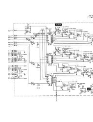
RELEASETIMESUSTAINVOLTAGEDECAYTIMEATTACKTIMELEFTOUTPUTINITIAL GAININITIAL FILTER FREQUENCYINITIAL OSCILLATOR FREQUENCYINITIAL OSCILLATOR FREQUENCYINITIAL OSCILLATOR FREQUENCY10 100 1KHz 10KHz.03 .3 3.0 30RANGEPAN10 100 1KHz 10KHz10 100 1KHz 10KHz.03 .3 3.0 3010 100 1KHz 10KHz.03 .3 3.0 30FINE TUNEX1000X100X10INFINE TUNEFINE TUNEFINE TUNE0GAIN MAXLEFTINPUTRESONANCEMIN MAXRIGHTINPUTPULSE WIDTH10% 50% 90%PULSE WIDTH10% 50% 90%PREAMPLIFIERSAWTOOTHTRIANGLE SAWTOOTHSAWTOOTHOUTMIXERA D S ROUTPUTSVOLTAGECONTROLLEDOSCILLATORVCO-3OUTPUTSOUTVOLTAGECONTROLLEDAMPLIFIERVOLTAGECONTROLLEDOSCILLATORVCO-2OUTPUTSOUTPUTVOLTAGECONTROLLEDFILTER/RESONATORVCFOUTPUTENVELOPETRANSIENTGENERATORDECAYSUSTAINRELEASEVOLTAGECONTROLLEDOSCILLATORVCO-1PULSEPULSESINESQUAREOUTRINGMODULATORENVELOPEFOLLOWERRELEASETIMEOUTPUTMANUALSTARTATTACKTIMEPWMREVERB-ERATORATTACKRELEASE ENVELOPETRANSIENTGENERATOROUTAUDIOKBD ONKBD OFFAUDIOKBD ONKBD OFFAUDIOKBD ONKBD OFF2ATTACKKEYBOARDGATE/TRIGL FL FL FCONTROLAUDIOCONTROLAUDIOFM CONTROLPULSE WIDTHMODULATIONFM CONTROLFM CONTROLLINEAR EXP’LAUDIOA RAUDIODCTRIGGATEMIXEROUTVCAVCFRINGMOD AR ADSRVCFS/HGATE3VCOKBDCV ADSRVCO VCO VCO1 2NOISEGENRINGMODVCO2KBD NOISECV GEN ADSRVCONOISE1GENKBD S/HCV OUT ADSRVCO2KBD S/HCV OUT ADSRVCO2VCO1PRE-AMPPOWERSAMPLE & HOLD1-10VRIGHTSPEAKER2NOISE GENERATORAMAXLEFTSPEAKERKBDCVNOISEGEN3WHITEOUTELECTRONICSWITCHKBDCV4ARP MODEL 2600BINTCLOCKOUTINVERTER5+10VS/HOUT6NOISEGENOUTPUTPINKINVERTERCENV FOLLMULTIPLESTEREOPHONESLEVEL RATE INTERNALCLOCKEXTCLOCKIN7 LAGLOWFREQMINDiagram 1-1 indicates the proper setting <strong>of</strong> each knob, switch and slider when the ARP 2600 is zeroed. The upperdiagram represents the 2600’s cabinet while the small lower diagram represents the controls on the keyboard.EXT.VIBRATOINLFOPORTAMENTOFOOTSWITCHARP made several different versions <strong>of</strong> the 2600. These are easiest to tell apart by the markings on the cabinets.The earliest models featured blue metal cabinets and a long wooden handle across the top. This model also lacksfine tune controls on VCO-1 and the VCF. While these models were very stylish, they were not particularly roadworthy.Later models featured a gray cabinet face in a wooden box covered in black Tolex (a vinyl-like substancewhich is very durable). These models also had a small plastic handle on the top <strong>of</strong> the cabinet and on the keyboard.These models are the most <strong>com</strong>mon version <strong>of</strong> the 2600, and one can be seen in Figure 1-1. The last 2600’sARP produced had a dark gray face with orange and white lettering, again in the Tolex case.LFO LFODELAYUPPERVOICEINTERVALLATCHKYBDSINGLEAUTOMULTIPLEVIBRATODEPTHVIBRATODELAYLFOSPEEDREPEATTRIGGERMODEON2 OCTAVESUPOFFMOMEN.ARP also produced several different models <strong>of</strong> keyboards. The last ones produced have significantly more featuresthan the early models (more on this in Section 13). The keyboard controls shown in the diagram are thosefrom the model 3620 keyboard, which was the last model ARP produced.2 OCTAVESDOWNPITCH BENDPORTAMENTOTRANSPOSEDIAGRAM 1-1003
004 - SECTION ONE: GENERAL CONTROLSPARAMETERS AND VALUESSoon the synthesizer’s functions will be explained, but it is important to first understand the concept <strong>of</strong>a parameter. A parameter is simply something that one can change. A value is one <strong>of</strong> the possiblesettings <strong>of</strong> a parameter. For instance, if Bob looks at a light switch, he can see that the switch itselfrepresents the parameter. It is something whose value he can change. This parameter has two possiblevalues: On and Off. A fader, on the other hand, is said to have an infinite number to values, although itsrange <strong>of</strong> values may be measurable.PATCH CABLESThin cables called patch cords or patch cables (See Figure 1-5) are used toconnect different parts <strong>of</strong> the synthesizer together. They consist <strong>of</strong> twoplugs which have been soldered to either end <strong>of</strong> a length <strong>of</strong> wire. Thiswire can be <strong>of</strong> any length. Some setups <strong>of</strong>fer cables <strong>of</strong> just one length,while other setups have many different lengths <strong>of</strong> cables. The cablesARP included with the 2600 were all <strong>of</strong> the same length, but few <strong>of</strong>them are still around today as the wire has usually deteriorated to thepoint where the cables are unreliable. Many owners <strong>of</strong> 2600’s todayeither purchase cables from <strong>com</strong>panies which specialize in cables ormake their own from parts acquired from electronics stores and supplyhouses.Figure 1-5: Twohomemadepatch cordsPatch cables are pretty durable, but one must take care <strong>of</strong> them if theyare expected to last a long time. First, don’t ever leave them lying aroundon the floor as they can be stepped on or worse yet, rolled over with achair. Second, whenever a patch cord is removed from ajack in the ARP’s cabinet, pull it out by the plug ratherthan by the cord. It is entirely possible to rip the cord right <strong>of</strong>f <strong>of</strong> the plug if it ispulled hard enough, because the only thing holding the two together is a drop <strong>of</strong> solder.Third, do not bend the cable itself at tight angles, as doing so can actually sever the wire inside thecasing. Finally, when finished with them, patch cords should be stored in a safe location, away fromextreme heat and <strong>of</strong>f the floor where they could be<strong>com</strong>e damaged. A simple hook mounted on a wall orthe side <strong>of</strong> a table is a great place to store patch cables.Many studios use two different colors <strong>of</strong> patch cables when patching the ARP 2600; red and black. Thecables are identical other than the color <strong>of</strong> the plug and/or wire casing, and don’t function any differently,but they are used for different purposes to make it easier to understand the way the synthesizerworks. For audio signals, black cables are used. Audio signals are signals that are the raw sound thatone eventually wants to hear. Red cables are used to carry control signals. Control signals are signalswhich one doesn’t intend to hear and which will be used strictly to effect change on some other part <strong>of</strong>the synthesizer. (The difference between audio and control signals will be<strong>com</strong>e clearer in time.) Thenext section contains a great deal more information about control signals. For now, just remember thatblack is used for audio signals, and red is used for control signals.
SECTION ONE: GENERAL CONTROLS - 005MODULAR SYNTHESIZERS AND CONNECTIVITYA modular synthesizer is a synthesizer that is made up <strong>of</strong> several different discreet devices which caneasily be seen and can be connected to each other in any order the user pleases. These devices are calledmodules. Almost all <strong>of</strong> these modules are housed in the synthesizer’s cabinet. On the ARP 2600, it ispossible to actually see the individual modules. They are separated on the front panel <strong>of</strong> the cabinetwith heavy white lines. With larger modular synthesizers, <strong>com</strong>panies <strong>of</strong>ten allowed users to pick andchoose which modules they wanted to make up a particular synthesizer, and as such, the modules wereentirely separate devices which didn’t share a <strong>com</strong>mon front panel. On a truly modular synthesizer,these different modules are not connected to each other, and the user must connect them together usingpatch cords to create sounds. This last point is very important, so keep it in mind.The patch cords are plugged into little holes on the modules called jacks. These jacks grip the ends <strong>of</strong>an inserted patch cord and make an electrical connection. The ARP 2600 uses 1/8 inch phono jacks (seeFigure 1-6) and as such, patch cords must have 1/8 inch phono plugs. Although they alllook the same, it is very important to understand that not all jacks are the same. Some jacksare inputs, and some jacks are outputs. A jack which allows signals to <strong>com</strong>e in is called aninput, and a jack which puts out signals is called an output. An input must be connected toan output. Likewise, an output must be connected to an input. Connecting an input to aninput or an output to an output won’t do anything at all. This is analogous to holding theFigure 1-6:two 1/8”jackshandset <strong>of</strong> a telephone upside down. Before patching two jacks together, it is very importantto make sure that one <strong>of</strong> them is an input, and one <strong>of</strong> them is an output. Otherwise, theconnection being made won’t do anything.The ARP is really a good teacher in that it is very forgiving. If a silly connection is made, such asconnecting an input to an input, or connecting an output to an output, it will not hurt the ARP at all. Justremember: signals can only <strong>com</strong>e out <strong>of</strong> an output; they can not go in. Signals can only go into an input;they do not <strong>com</strong>e out.MODULAR: THE PROS AND CONSThere are some great advantages to modular synthesizers. First and foremost, one could connect themodules in any order. It is possible to <strong>com</strong>e up with some pretty wild <strong>com</strong>binations which are notpossible when dealing with a non-modular synthesizer (called a fixed-architecture synthesizer). Additionally,students can see each individual module and experiment with them individually, instead <strong>of</strong>having to use them in predetermined order.There are, <strong>of</strong> course, disadvantages to modular synthesizers as well. First, to create a sound, one mustuse several patch cords. Secondly, all <strong>of</strong> the knobs and sliders must be reset for each different sound, asmost modular synthesizers can’t recall a programmer’s sounds. Most modular synthesizers also allowthe performer to play only one note at a time. Because <strong>of</strong> this, they are said to be monophonic. Manymodular synthesizers are also be<strong>com</strong>ing vintage instruments (older than 25 years) at this time and arebe<strong>com</strong>ing more and more unreliable. Despite all <strong>of</strong> these limitations, there is a large potential formaking interesting sounds, and wonderful music.
006 - SECTION ONE: GENERAL CONTROLSARE SYNTHESIZERS NORMAL?When sounds are created on the ARP 2600, certain modules must be connected in a certain way, and theappropriate knobs and sliders must be set just right to produce the desired sound. This collection <strong>of</strong>settings <strong>of</strong> patch cables, sliders, and knobs is called a patch. The term ‘patch’ <strong>com</strong>es from the patchcables used make these sounds. Modern synthesizers don’t use patch cables, but individual sounds arestill referred to as ‘patches’.All <strong>of</strong> this patching can be a lot <strong>of</strong> work, and many times, it is desirable to use the modules in astandard configuration (see Section 8 for more information). It would be very time consuming andmonotonous constantly creating the same patches again and again, so the designers <strong>of</strong> the ARP 2600came up with a good solution: normals.What is a normal? A normal is simply a connection which is made to one <strong>of</strong> the ARP’s input jacks fromone <strong>of</strong> the ARP’s outputs even before a patch cord is plugged into it. Another way to say this: Someoutputs are internally wired to some inputs. All but eight <strong>of</strong> the ARP 2600’s inputs have somethingnormalled to them. One can tell if an input has something normalled to it because there is some writingin a small white box that points to the input. The writing indicates what is normalled to that input.Another way to think <strong>of</strong> a normal is as a connection that is premade with an invisible patch cord. It isnot possible for a user to change what is normalled to each input.BUT WHAT IS NORMAL?The normal represents the patch which is most <strong>com</strong>monly used. The ARP’sdesigners made the everyday connections into normals. They didn’t normalmodules together that one would rarely connect. Thus, it is importantto take note <strong>of</strong> which modules are normalled together, as this will give astudent some clues as to how the synthesizer will ‘normally’ be patched.However, there are times when it is undesirable to make that particularpatch or connection which is made by a normal. This is the time when theinput jack will be used, and the normal will be broken. Breaking a normalmeans disconnecting that premade electrical connection in the synthesizer.To break a normal, all one must do is plug a patch cord into an inputjack. When a patch cord is connected to an input jack, two things actuallyhappen: First, the normal is broken and what was formerly connected tothat input is now disconnected. Second, whatever is traveling down thatpatch cord is now connected to the input.Figure 1-7: Nobody’sfool. Two dummy plugsA great example <strong>of</strong> a normal is the headphone jack. The headphone jack is actually an output, since itputs out a signal for headphones, but it still represents a normal. Sound is normalled from the synthesizer’sinternal amplifier to the synthesizer’s speakers. When a pair <strong>of</strong> headphones is plugged into the headphonejack, that normal is broken, and no sound can emerge from the speakers. The ARP 2600 hasthirty-nine inputs that have something normalled to them.
SECTION ONE: GENERAL CONTROLS - 007DUMMY PLUGSWhile normals are very convenient, there are times when it is desirable to break a normal withoutconnecting anything to that particular jack. A synthesist might want to connect a module other than theone which is preconnected by the normal. One possible solution to this problem is to just plug one end<strong>of</strong> a patch cord into the jack, but the problem with this is that the other end <strong>of</strong> the cord can touch objectsin the studio and create electrical noise. The cable could also pick up electromagnetic interference andadd even more unwanted noise. A dummy plug is a much better solution to this problem.A dummy plug (see Figure 1-7 on page six) is just a plug from a patch cord without the cord. Using adummy plug, a normal can be broken without all <strong>of</strong> the disadvantages <strong>of</strong> plugging in one end <strong>of</strong> a patchcord. Throughout the experiments with the ARP that follow, the reader will make use <strong>of</strong> the dummyplug.MODULAR VS. SEMI-MODULARAs mentioned before, on a truly modular synthesizer, none <strong>of</strong> the modules are actually connected. Ofcourse, normals actually make some connections between modules without using patch cords. So itwould seem that the ARP 2600 is not actually a modular synthesizer. This is true; the ARP 2600 is nottechnically a modular synthesizer. It is still possible to use it as a modular synthesizer, though, and itretains all <strong>of</strong> the advantages <strong>of</strong> a modular synthesizer without some <strong>of</strong> the inconveniences. Because <strong>of</strong>these subtle differences, the ARP 2600 will be referred to as a semi-modular synthesizer. Basically,‘semi-modular’ simply means that many <strong>of</strong> the modules have normalled connections.CLONING IN THE SYNTHESIZER WORLD(OR: MULTIPLES AND HOW TO USE THEM)One <strong>of</strong> the first modules one will encounter on the ARP 2600 synthesizeris the multiple. It is fairly easy to understand and use, and it really adds tothe flexibility <strong>of</strong> the synthesizer. The multiple, which is located in thelower left hand corner <strong>of</strong> the cabinet, simply makes extra copies <strong>of</strong> anysignal. (See Figure 1-8) The multiple is made up <strong>of</strong> four jacks, which areall wired together internally. If one connects an output to any one <strong>of</strong> thosejacks, three identical copies will <strong>com</strong>e out the other jacks. This duplicationoccurs regardless <strong>of</strong> which jack one plugs into. Using the multiple, itis possible to make up to three copies <strong>of</strong> a signal. This will really <strong>com</strong>e inhandy later on.Figure 1-8: The <strong>ARP2600</strong>’s multiplesConversely, it is possible to plug three different signals into the multiple,they will be summed, and will all be output at the remaining multiplejack. While this is possible, it is not re<strong>com</strong>mended. To properly mix signalstogether, they must be passed through a device called a mixer, whichwill be explored a bit more in Section 6.
008 - SECTION ONE: GENERAL CONTROLSCONTROL VOLTAGES AND VOLTAGE CONTROLTo make a sound, different synthesizer modules are connected together using patch cords. However,the system that these modules use to control each other hasn’t been explained yet. Several differentsystems have <strong>com</strong>e and gone over time. The ARP 2600 uses one <strong>of</strong> the earliest, and most primitive. (Itis one <strong>of</strong> the easiest to understand, though!) The 2600 uses a system called voltage control to sendsignals from one module to another.In a voltage control system, modules send out a raw electrical voltage that represents a value. Thegreater the voltage, the higher the value it represents. This voltage is called a control voltage. The termvoltage control is used to describe a system where these control voltages are used. Synthesizers do notuse a lot <strong>of</strong> voltage to send these signals, so one is never in danger <strong>of</strong> getting an electrical shock fromthe synthesizer, as long as the cabinet is not opened, which is fairly difficult to do, anyhow.Another way to remember these two, similar sounding terms is to remember that ‘voltage control’ isusually used as an adjective. It describes a synthesizer or a module <strong>of</strong> a synthesizer (e.g. the ARP 2600is a voltage controlled synthesizer). Meanwhile, ‘control voltage’ is a noun. One might say that acontrol voltage is being produced by a certain module.VOLTAGE CONTROL, PARAMETERS & VALUESVoltage control will be discussed in greater detail in the next section when it is possible to actually hearits effects. For now, students should just try to understand the basic concept. Earlier on in this sectionit was said that a parameter is something that can be changed, and the possible settings <strong>of</strong> that parameterare its possible values. On the ARP 2600, parameters are represented by control inputs. Values arerepresented by control voltages. By connecting a control voltage to an input jack, that value is assignedto whatever parameter the input jack represents. This will be<strong>com</strong>e clearer over time, especially when itappears again in the next section.KEYBOARD CONTROL VOLTAGEOne device that creates control voltages is the keyboard. It was mentioned earlier in this section that thekeyboard receives voltage from the cabinet through its connecting cable. However, the keyboard isalso returning several signals <strong>of</strong> its own, one <strong>of</strong> which is the keyboard control voltage. The higher thekey played, the greater the voltage the keyboard sends out. This voltage goes back to the cabinet and<strong>com</strong>es out the Keyboard CV output jack on the front panel <strong>of</strong> the cabinet. This jack is located just abovethe multiple and can be seen in Figure 1-8 on page7. This voltage is then used to control the pitch <strong>of</strong> theoscillators, as will be explained in the next section.
SECTION ONE: GENERAL CONTROLS - 009EXPERIMENTS FOR SECTION ONE:1. Demonstrate left to right signal flow on the ARP’s cabinet. Why is the synthesizer designed thisway?2. Locate the keyboard and the cabinet <strong>of</strong> the ARP 2600.3. Locate the cable which connects the keyboard and the cabinet.4. Demonstrate the technique for ‘zeroing’ the synthesizer and demonstrate power-up procedure.5. Locate main power switch, the light above it, and main power cord.6. Locate an input, and notice the symbol below it indicating its normal.7. Locate the speakers and their volume sliders.8. Locate the headphone jack. Demonstrate what happens to the speakers when headphones are pluggedinto the headphone jack. What is this phenomenon called?9. Demonstrate correct use and care <strong>of</strong> patch cords. Notice the colors and different lengths.10. Demonstrate a dummy plug.11. Locate the multiple on the front panel <strong>of</strong> the ARP.12. Locate the keyboard control voltage output on the front panel.
010 - SECTION ONE: GENERAL CONTROLSREVIEW QUESTIONS FOR SECTION ONE:1. When was the ARP 2600 made? Is this a typical production time span for a synthesizer?2. Why is the synthesizer designed to let signals flow from left to right? What was the primary goal <strong>of</strong>designing the ARP 2600 synthesizer?3. Name the two main parts <strong>of</strong> the ARP 2600. Is it possible to use one part without the other? What isone purpose <strong>of</strong> the cable that connects the two parts?4. What must be done before the synthesizer is turned on to avoid damage to other studio devices?5. What happens to the speakers if you plug headphones into the synthesizer? How is this a littleunusual?6. What does ‘zeroing the synthezier’ mean? Why is it important to zero the synthesizer before using it?7. How should patch cords be treated to protect them? Which cable generally represents which signal?8. List the advantages and disadvantages <strong>of</strong> modular synthesizers.9. Describe how modules are patched together.10. What is the difference between Voltage Control and Control Voltage?11. How does voltage control relate to parameters and values?12. Where does the main power cable connect to the cabinet?13. Should inputs be connected to inputs or outputs?TERMS TO KNOW:Audio SignalControl SignalControl VoltageDummy PlugFixed-architecture SynthesizerInputJackKeyboard Control VoltageModularModuleMonophonicMultipleNormalOutputParameterPatch CablePatchSemi-ModularValueVoltage ControlZero
SECTION2 VCO-1ALL ABOUT OSCILLATORSOscillators are the fundamental part <strong>of</strong> any synthesizer. They are the module that creates the raw soundthat will be shaped and molded by all the other parts <strong>of</strong> the synthesizer. Oscillators function by puttingout voltage in a pattern. The faster they put out the pattern, the higher the frequency they produce.When this output voltage is amplified and connected to a speaker, a sound can sometimes be heard.Some people think that oscillators only put out voltage when a key is being played on the keyboard.This really isn’t true, though. Oscillators constantly oscillate at a specified rate, even if a key isn’t beingplayed. Another word for rate is frequency and it is measured in Hertz (Hz).+10Volts0timeFigure 2-1: A square waveVCO stands for voltage controlled oscillator. This means thatthis module is an oscillator and can produce audio signals andcontrol signals. It also means that at least one <strong>of</strong> its parameterscan be controlled via voltage control. This is another perfectexample <strong>of</strong> the term ‘voltage controlled’ being used as an adjectiveas mentioned in Section 1.Most oscillators are capable <strong>of</strong> producing different tone colors. This is ac<strong>com</strong>plished by putting outvoltage in a pattern called a waveform. For instance, to create a square wave (see Figure 2-1), theoscillator will put out no voltage for a moment, then put out ten volts for a moment. To produce a sawwave (see Figure 2-2), the oscillator must increase its voltage gradually to ten volts, then drop sharplyback to zero volts.Repeating a waveform very quickly (<strong>of</strong>ten thousands <strong>of</strong> timesper second) produces an electronic signal which human earswill perceive as a tone after it is amplified and is connected toa speaker. Notice when the raw output <strong>of</strong> an oscillator is connectedto a speaker that the sound is not particularly interestingto listen to. Because the sound is static and unchanging, it israther monotonous or boring.10volts0timeFigure 2-2: A saw waveTHE OSCILLATOR’S TIMBREOscillators have two different parameters, the first <strong>of</strong> which is timbre. Timbre <strong>com</strong>es from French, andis pronounced tam-ber. Timbre means tone color or raw sound. When timbre changes, the shape <strong>of</strong> thewaveform changes. One can easily see by <strong>com</strong>paring Figures 2-1 and 2-2 above that a square wavedoes not look anything like a saw wave. The two will sound different as well, just the way a pianosounds different from a trumpet, even if each sounds the same note.One selects a timbre by connecting a patch cord to one <strong>of</strong> the oscillator’s two outputs. In Figure 2-3,VCO-1’s two outputs jacks can be seen. The top jack constantly puts out a saw wave and the bottomjack puts out a square wave. It is very important to note that connecting a patch cord to one <strong>of</strong> the two011
012 - SECTION TWO: VCO-1outputs is the only way the timbre can be changed. For instance,if one wishes to hear a square wave, one must connect the squareoutput <strong>of</strong> VCO-1 to the speakers. The only way to change thetimbre that VCO-1 is creating is to manually connect the patchcord to the saw output. It is important to also realize that bothoutputs <strong>of</strong> an oscillator can be used at the same time so that bothtimbres can be heard simultaneously.Although everyone will perceive timbres slightly differently, it ispossible to make some generalizations about them which willguide the student in his or her studies. The saw wave has lots <strong>of</strong>harmonics, and as such has a sound that sounds buzzy. The squarewave, on the other hand, has only the odd harmonics, and as such,it has a rather hollow sound. Take a moment now to listen to CDtrack 01. Several tones are played by VCO-1. First, the notes areFigure 2-1:VCO-1’s saw and square outputs.played with a square wave produced by VCO-1. Then, the notes are played with a saw wave producedby VCO-1. Remember to listen for the raw sound or timbre <strong>of</strong> the sound, and not how quickly orslowly the sound begins or ends.THE OSCILLATOR’S FREQUENCYThe second parameter <strong>of</strong> oscillators is frequency. Frequency is <strong>of</strong>ten referred to as pitch by musicians.While selecting a timbre is fairly simple, controlling frequency is a bit more involved. Frequency iscontrolled in several different ways. First, VCO-1 has a coarse frequency setting. This fader can changethe oscillator’s frequency over a very large range. It is possible to make the oscillator oscillate soquickly that it can’t be heard at all (a supersonic tone - 20 kHz or higher) or so slowly that a tone can’tbe perceived (a subsonic tone - 20 Hz or lower).When it is necessary to tune an oscillator to another source such as another oscillator, one needs betteroverall control than the coarse tuning slider can provide. This is the job <strong>of</strong> the fine tuning slider. (Theearliest version <strong>of</strong> the ARP 2600 lacked the fine tune control on VCO-1.) See page three for moreinformation.) The fine tuning slider increases or decreases the pitch a small amount from wherever ithas been set by the coarse tuning slider. When attempting to tune an oscillator to match another sourcesuch as another oscillator, one should get the frequency close to that <strong>of</strong> the other source using thecoarse slider, then tune it in perfectly using the fine tuning slider.As the oscillator’s tuning gets close to the pitch <strong>of</strong> the other source, a series <strong>of</strong> ‘beats’ can be heard.These beats are a sort <strong>of</strong> pulsing in the sound which occur when the waveforms <strong>of</strong> the two sourcesalternately cancel and reinforce each other. This results in a small change in volume which is perceivedas beats. As the frequency <strong>of</strong> the two sources gets closer and closer together, the beats will graduallyslow until finally, they stop, indicating that the two sources are perfectly in tune. Take a moment nowto listen to CD track 02. Two oscillators are being tuned together. Listen for the slowing <strong>of</strong> the beats asthey get closer to being in tune.
SECTION TWO: VCO-1 - 013MODULATION: THE KEY TO THE WORLD OF SYNTHESIZERSThe third way the oscillator’s frequency is controlled is by the amount <strong>of</strong> voltage that it receives. Thisis why this oscillator is called a Voltage-Controlled Oscillator; its frequency can be controlled by anexternal voltage. The more voltage the oscillator is fed, the higher the frequency or pitch it will produce.Things to this point have been pretty straightforward, but now <strong>com</strong>es the tricky part. On synthesizers,a technique called modulation is frequently used. Modulation allows one module to change the value <strong>of</strong>a parameter <strong>of</strong> another module. The easiest way to understand modulation is by looking at an example.If Wendy is riding in a car and she is attempting to draw a straight line across a piece <strong>of</strong> paper, she couldrepresent a module on a synthesizer. The line Wendy is trying to draw on the paper is the parameterwhich can be changed. When the driver drives over some big bumps in the road, Wendy’s straight lineis going to be changed with each bump she rides over. So, the road is changing the value <strong>of</strong> Wendy’sline. Instead <strong>of</strong> a nice straight line, she might end up with one that goes all over the page. What is reallyhappening here is that the texture <strong>of</strong> the road is modulating Wendy’s drawing.Whenever modulation occurs, there is a carrier and a modulator. The carrier is the module whoseparameter is being changed (Wendy’s drawing in the example above). The modulator is the modulethat is doing the changing (the road in the example above).Understanding modulation is the key to understanding modular synthesis. Although modular synthesisis called “modular synthesis” because it involves different modules, it might just as well have beencalled “modular synthesis” because the individual modules change, or modulate each other. Understandingmodulation is the key to understanding the ARP 2600. Once the concept <strong>of</strong> modulation isunderstood, everything else be<strong>com</strong>es much more clear, and more <strong>com</strong>plex patches can be attempted.FREQUENCY MODULATIONWhile it is not possible to modulate the timbre <strong>of</strong> VCO-1 from another source (remember: the only wayto switch timbres on VCO-1 is to manually plug the patch cord into a different output), it is possible tomodulate the frequency using a control voltage. (This process will be dealt with in depth in the nextsection.) When the frequency <strong>of</strong> an oscillator is being modulated, this technique is called frequencymodulation. Frequency modulation is <strong>of</strong>ten abbreviated ‘FM’.To modulate the frequency <strong>of</strong> VCO-1, a control voltage must be connected to one <strong>of</strong> the four jacksbelow VCO-1. (See Figure 2-4 on page 14) These jacks are called frequency modulation inputs andthey are labeled “FM CONTROL” on the cabinet’s panel. When a control signal (like the controlvoltage output <strong>of</strong> the keyboard) is connected to one <strong>of</strong> these inputs, the stage is set to modulate thefrequency <strong>of</strong> the oscillator. However, the ARP gives the user some options here. The observant studentwill notice that there is something normalled to each FM input jack. These devices will all be discussedin time. One <strong>of</strong> the most <strong>com</strong>mon examples <strong>of</strong> frequency modulation is a control voltage from thekeyboard modulating the frequency <strong>of</strong> an oscillator.
014 - SECTION TWO: VCO-1When plugging into the FM three jacks on the right <strong>of</strong>VCO-1, the user can control the amount <strong>of</strong> controlvoltage that will actually get to the oscillator. Whenthe slider or fader (the two terms are used interchangeablyin this book) above a jack is all the way down, nosignal will be passed to the oscillator from that jack.When the slider is all the way up, all <strong>of</strong> the in<strong>com</strong>ingcontrol signal will be allowed to modulate the oscillator.When a fader is all the way down (or all the wayto the left) it is said to be closed. Conversely, whenthe slider is set all the way up (or all the way to theright) it is said to be open.The left most FM CONTROL jack is normalled to thekeyboard’s control voltage. One can tell that the keyboardcontrol voltage is normalled to this input sinceFigure 2-4: VCO-1’s FM jacksthe words “KBD CV” appear in the white box under the input. Since it is keyboard CV that is normalledhere, it is usually desirable to have all <strong>of</strong> the keyboard control voltage modulating the frequency<strong>of</strong> the oscillator. Thus, there is no fader above this input, and all <strong>of</strong> the in<strong>com</strong>ing control signal willalways modulate the oscillator. If a fader was present above this jack, then all <strong>of</strong> the voltage would notget to the VCO, and the keyboard would not produce chromatic half steps from one note to the next.There is some use for this technique, and it will be explored later in this section. Frequency modulationis the final way that Figure 2-5 below sums up all <strong>of</strong> the ways VCO-1’s frequency can be changed.THE KEYBOARD AND REDUNDANT PATCHESVCO-1VCO-1’s frequencyis determined by:• Coarse Tune• Fine Tune• Control Voltageconnected to FMinputs. (This includes the keyboardCV normal)Figure 2-5The control voltage produced by the keyboard is normalled to each oscillator.When the keyboard is played, it sends out a control voltage for each key, andthe oscillator will change its frequency depending upon how much voltage itreceives from the keyboard. This is a great example <strong>of</strong> voltage control discussedin Section 1. This is how the synthesizer is able to play different pitcheswhen different notes are played on the keyboard. The keyboard’s normal to theoscillator can be broken by inserting a dummy plug into the Keyboard CV jack.Sometimes people have trouble remembering that the keyboard’s control voltageis normalled to the oscillators. It is possible to patch the keyboard’s controlvoltage output on the front panel to the keyboard control voltage FM input onVCO-1, but this is not necessary, since the keyboard control voltage is alreadynormalled to each oscillator. Creating this patch would just be redoing what thenormal has already ac<strong>com</strong>plished. If a patch is created which duplicates theeffect <strong>of</strong> a normal, it is called a redundant patch. Patching the keyboard CVoutput to the keyboard CV jack on VCO-1 is a perfect example <strong>of</strong> a redundantpatch. This redundant patch is illustrated in Figure 2-6 on Page 15. (The heavyred line represents a patch cord.)
SECTION TWO: VCO-1 - 015KBDCVOUTPUTVCO-1FM CONTROLFigure 2-6: A <strong>com</strong>mon redundant patchRedundant patches should be avoided forseveral reasons. First, they use a patch cordwhich could otherwise be used for someother purpose. At first, it might seem asthough one would never actually use all <strong>of</strong>the available patch cords in a studio at once,but as additional synthesis techniques are discovered,experimenters will want to createever more <strong>com</strong>plex patches which will requiremany patch cords. Secondly, whenevermore cables are used in an electronic musicsetup, there is a greater chance for things togo wrong. Jacks sometimes go bad, cablessometimes go bad, and cables can pick up hum from other electrical devices and even radio waves.Redundant patches make troubleshooting a patch much harder since they introduce so many variables.Normals have a fairly low failure rate, and it is much better to make use <strong>of</strong> them rather than using patchcords whenever possible.LFO’S AND VCO’SVCO-1 also leads a double life as a low frequency oscillator. By moving the Audio/LF switch (upperleft hand corner <strong>of</strong> Figure 2-4 on page 14) to the lowest position, VCO-1 will oscillate in the sub-audiorange. Sub-audio means that the pitch is so low (the frequency is so slow) that humans aren’t able tohear a tone. Instead, a repeating series <strong>of</strong> clicks is audible. When a VCO is in low frequency mode (LFmode for short) it is a low frequency oscillator, which is abbreviated LFO. Knowing what is nowknown about frequency modulation, think about how one oscillator in LFO mode could be used to FManother oscillator. (This is actually discussed in detail in the next section.)As the frequency <strong>of</strong> the oscillator in low frequency mode is increased, the oscillator will eventuallyreach a point where a tone can be heard. This happens around 20 Hz, or 20 cycles per second, which isabout the lowest pitch human beings can hear. Listen to CD track 03. One can hear the sound <strong>of</strong> anoscillator in low frequency mode and its frequency is gradually being increased so that it eventuallyreaches the audible range.When a VCO is in low frequency mode, the keyboard control voltage normal is broken. This meansthat the keyboard CV will no longer reach the oscillator. This is desirable because an LFO is expectedto oscillate steadily at one frequency and the keyboard CV would change the frequency at which theLFO was oscillating. Usually, LFO’s are used to create vibrato, which will be discussed in the nextsection. For the rare occasions when a synthesist wants an LFO’s frequency to follow the keyboard CV,the synthesist can use a patch cord to connect the keyboard CV output jack to one <strong>of</strong> the FM input jackson the oscillator. The label to the right <strong>of</strong> the LF switch reminds the user that the keyboard will bedisconnected when the switch is set to the low position. It says “KBD ON” near the audio position, and“KBD OFF” near the LF position.
016 - SECTION TWO: VCO-1EXPERIMENTS FOR SECTION TWO:1. Listen to the raw sawtooth output by patching oscillator directly to an input on the mixer (yourteacher can help you with this). Describe the timbre.2. Listen to raw square output by patching oscillator directly to an input on the mixer. Describe thetimbre. CD track 013. How else can the timbre the VCO is producing be changed without moving the patch cord?4. Patch both wave outputs into the mixer. Is it possible to hear both timbres at once?5. Control the frequency <strong>of</strong> VCO-1 by moving the INITIAL FREQUENCY slider. Try to play a simplesong. Is this and effective way to control the frequency <strong>of</strong> an oscillator? Now control the pitchusing the FINE TUNE slider.6. While listening to either output <strong>of</strong> VCO-1, play the keyboard and notice that VCO-1’s pitch changes.What is occurring here?7. Create a redundant patch by connecting the keyboard’s CV output to the FM input labeled “KYBDCV”. Notice that this has the same effect as the normal in experiment #6.8. Insert a dummy plug into the FM control input labeled “KYBD CV” on VCO-1 and play the keyboard.What is occurring now?9. Put VCO-1 in LF mode using the Audio/LF switch. Lower the initial frequency slider so that it isopen only about 1/4. What sounds do you hear when listening to the saw wave? When listeningto the square wave?10. After conducting experiment #9, try playing the keyboard. What happens and why?11. Starting in the sub-audio range (LF mode), slowly bring VCO-1’s frequency into the audio range.Notice the point at which one can first hear a tone. CD track 0312. Zero VCO-1, then practice frequency modulation on VCO-1 by using a dummy plug to break thekeyboard CV normal on the left most FM input. Then patch the Keyboard CV output to one <strong>of</strong>the other FM inputs and fully open the slider above that jack. How is this not as desirable asusing the normal from the keyboard CV? What happens if you set the slider in a position otherthan fully open or fully closed? What is noticeable about the pitch even when the slider is fullyopen?13. How many notes can VCO-1 produce at one time?
SECTION TWO: VCO-1 - 017REVIEW QUESTIONS FOR SECTION TWO:1. Describe an oscillator’s function and role in the synthesizer, and tell how it works.2. Explain when oscillators oscillate, and tell why the raw sound they produce is rather boring.3. Name the oscillator’s two parameters, and the way both can be changed from the oscillator itself.4. Tell how many different waveform outputs can be used at once from VCO-1.5. List the three things that determine a VCO’s pitch.6. Describe the timbre <strong>of</strong> saw and square waves.7. Describe the best way to tune VCO-1 to another source.8. Describe how the keyboard is connected to VCO-1.9. List three reasons why it is highly desirable to avoid redundant patches.10. Give an example <strong>of</strong> modulation. Be sure to include the words carrier and modulator in your explanation.Tell why it is so important to understand modulation.11. Give an example <strong>of</strong> frequency modulation. Also, describe what connections must be made to frequencymodulate an oscillator.12. Speculate how an LFO will be useful later. Tell how to put a VCO into LF mode. Describe whathappens to the keyboard CV normal to VCO-1 when VCO-1 is put into LF mode.13. How many FM control inputs does VCO-1 have?TERMS TO KNOW:CarrierClosedFaderFrequencyFrequency ModulationFrequency Modulation InputsHertzLF ModeLFOModulationModulatorOpenOscillatorPitchRedundant PatchSawtooth WaveSliderSquare WaveSubsonicSupersonicTimbreVCOWaveform
SECTION3VCO-2A FIRST LOOKIn Section 2, a basic voltage controlled oscillator (VCO-1) was discussed in detail. In this section,VCO-2 will be examined. Although VCO-2 is more <strong>com</strong>plex than VCO-1, all <strong>of</strong> the things that weresaid about VCO-1 apply to VCO-2. VCO-2 can be thought <strong>of</strong> as the ‘super oscillator’ on the ARP 2600since it is the most flexible, and thus the most powerful oscillator <strong>of</strong> the three found on the 2600. Thefirst thing one notices when looking at VCO-2 for the first time is the additional waveforms thatVCO-2 can produce. In addition to the saw wave, VCO-2 can produce sine, triangle, and pulse waves.SINE WAVESSine waves (see Figure 3-1) have a very pure sound, becausethey have only one harmonic, and that is the fundamental.CD track 07 It is also important to note that whilethe square and saw waves that VCO-1 produced ranged between0 Volts and +10 Volts, the sine wave VCO-2 producesranges between -5 Volts and +5 Volts. Overall, it still has thesame amplitude span as the waveforms VCO-1 produced,but because it dips into negative voltage, it is more flexible.When the sine wave output is used to modulate anothersource, it can actually send a negative value to that carrier,rather than just a positive value. This technique will be exploredin depth in a later section.+10V+5V0V-5V-10VtimeFigure 3-1: A sine waveTRIANGLE WAVESTriangle waves (see Figure 3-2) sound a little buzzy, butsmoother than a saw wave. Although they look very similar+10Vto a saw wave, they are actually most like square waves harmonically.CD track 07 Just like the square wave, they have+5Vonly the odd numbered harmonics. At first, this doesn’t seemtimeto make any sense. If the harmonic content <strong>of</strong> a waveform0Vdetermines its shape, and the triangle and square waves bothhave the same harmonics, shouldn’t they look alike and sound-5Valike? Actually, it is possible for two different waveforms to-10Vhave the same harmonics present, but present in differentamounts. In the triangle wave, some <strong>of</strong> the upper harmonicsare present in higher amounts than in the square wave. ThisFigure 3-2: A triangle wave gives it a buzzy sound which is different from the squarewave. It is also important to note that like the sine wave, the triangle wave ranges from -5 Volts to +5Volts, meaning that it can send a negative value to a carrier when it is being used as a modulator.018
SECTION THREE: VCO-2 - 019NOT JUST ANOTHER PRETTY PHASEWhen two waveforms begin and end together, they are said tobe in phase with each other. In Figure 3-3, one can see that thetwo sine waves shown are in phase with each other. (The twooverlapping sine waves are represented by the thick red line.)When two identical waveforms are in phase with each other, aninteresting thing happens. They are summed, and the result thathumans hear is louder than the amplitude <strong>of</strong> either <strong>of</strong> the waveformsalone. This phenomenon is called reinforcement. In Figure3-3, the taller black line shows the result <strong>of</strong> the two red sinewaves being summed.timeA waveform’s cycle can be measured in 360 degrees like a circle.In Figure 3-4, some <strong>of</strong> the important phase angle marks areindicated. When one waveform starts halfway though the cycle Figure 3-3: Reinforcement<strong>of</strong> another waveform, the two are said to be 180 degrees out <strong>of</strong> phase, since half <strong>of</strong> 360 is 180. Similarly,if one waveform starts a quarter way through another waveform’s cycle, the two would be 90degrees out <strong>of</strong> phase. This measurement is called the phase angle. When two waveforms are 180degrees out <strong>of</strong> phase with each other, and the waveforms are identical, a strange phenomenon occurs.Because the crest <strong>of</strong> one wave occurs at the same time as the trough <strong>of</strong> another, the two cancel eachother out, and the listener perceives a reduction in volume. This phenomenon is called cancellation. Inthe real world, it is very difficult to get two waveforms to cancel each other out <strong>com</strong>pletely, even undercarefully controlled circumstances.PHASE RELATIONSHIPSThe triangle and sine outputs <strong>of</strong> VCO-2 have an important quality: They are 180 degrees out <strong>of</strong> phasewith each other. In Figure 3-4, one can see that the triangle wave (green) reaches its highest amplitudeat 90 degrees, just when the sine wave is at itslowest amplitude. However, if the triangle andsine waves are added together, they will not canceleach other out. Remember that the two havedifferent waveforms, and a different harmonic content.The sine wave has only the fundamental, andas such, it will only cause cancellation <strong>of</strong> the trianglewave’stimefundamental.The phase relationship between the triangle andthe sine outputs is the most obvious and easiest toobserve. However, when dealing with simplewaveforms like the ones the ARP 2600 can produce,it is possible to say that two waveforms are180 degrees out <strong>of</strong> phase when the highest point0 90 180 270 0 90 180 270 0 phase angleFigure 3-4: The sine and trianglewaves are 180 degrees out <strong>of</strong> phase
020 - SECTION THREE: VCO-2<strong>of</strong> one waveform occurs at the lowest point <strong>of</strong> another. Thephase relationships <strong>of</strong> the other outputs can be easily summedup: outputs which are perpendicular to each other (i.e. abovebelow, or to one side) are 180 degrees out <strong>of</strong> phase. Thosediagonal to each other are in phase. Figure 3-5 illustrates thisrelationship. Red arrows represent out <strong>of</strong> phase relationshipswhile blue and green arrows represent in phase relationships.out <strong>of</strong>phaseTriangleout <strong>of</strong>phasein phaseSawtoothout <strong>of</strong>phasePULSE WAVESVCO-2 doesn’t really have a square wave output, but has apulse wave output instead. This is a very important featuresince a pulse wave is like a square wave, but is much moreflexible. Pulse waves, like a square wave, are partially “on”and partially “<strong>of</strong>f.” In terms <strong>of</strong> voltage, a pulse wave consists<strong>of</strong> ten volts for a moment, then zero volts for a moment. For a square wave, these two ‘moments’must be equal. In a pulse wave, they can be equal, but do not have to be equal. Thus, a square wave isreally just a kind <strong>of</strong> pulse wave.PULSE WIDTHOne important aspect <strong>of</strong> a pulse wave is that it is another parameter to change. That parameter is thepulse width. Of course, in Section 2, the reader learned that there are only two parameters <strong>of</strong> anoscillator one can change: frequency and timbre. One might think <strong>of</strong> pulse width as a sort <strong>of</strong>subheading under the ‘timbre’ parameter heading.Sineout <strong>of</strong>phasePulseFigure 3-5: The phaserelationships <strong>of</strong> VCO-2’s outputstime30% duty cycle50% duty cycletimeFigure 3-6: Pulse waves withdifferent duty cuclesPulse width is the name <strong>of</strong> the parameter that controls how much <strong>of</strong> thewave is ‘on’ and how much <strong>of</strong> the wave is ‘<strong>of</strong>f.’ Another name for pulsewidth is duty cycle. The duty cycle <strong>of</strong> a pulse wave is expressed as a percentage.The percentage tells how much <strong>of</strong> the duty cycle is ‘on.’ For instance,a pulse wave that has a pulse width <strong>of</strong> 20% would be a pulse wavewhich is ‘on’ 20% on the time, and ‘<strong>of</strong>f’ 80% <strong>of</strong> the time. Figure 3-6 illustratesa pulse width <strong>of</strong> 30%, and a pulse width <strong>of</strong> 50% (a square wave).Making changes in the pulse width changes the waveshape and thus thetimbre. This is why it is difficult to describe the pulse wave’s timbre: thetimbre changes significantly when the pulse width is changed. The timbrecan range from hollow when the duty cycle is near 50% to nasal when it isnearer 0% or 100%.On the 2600, changing VCO-2’s pulse width is simple. The pulse width ischanged by moving the PULSE WIDTH slider, right under the FINE TUNEslider. This control can be seen, along with VCO-2’s outputs and initialfrequency controls in Figure 3-7 on page 21. When the pulse width is set to50%, the VCO will produce a square wave (if it is properly calibrated).
SECTION THREE: VCO-2 - 021A NOTE ABOUT CALIBRATION: Throughout this text, the reader will see phrases such as “ifit is properly calibrated.” One may begin to wonder how calibration is achieved. Once again,different versions <strong>of</strong> the 2600 have slightly different methods <strong>of</strong> calibration. In most cases,there are small holes in the front <strong>of</strong> the cabinet, each <strong>of</strong> which has a trim pot inside. One suchhole can be seen in Figure 3-7. By inserting a standard screwdriver, one can turn the trim potand calibrate each module. On the first models produced (the “Blue Meanies,”) each calibrationhole was actually labeled with the function it calibrated. While this was highly userfriendly,it seems that it was also highly inviting, and many people managed to get their 2600’sout <strong>of</strong> whack before they were really familiar with them. By the time ARP made the grey faced2600’s, the labels had disappeared, and some <strong>of</strong> the less frequently used calibrations (such asthe high frequency tracking on the VCO’s) were moved inside the cabinet.In any case, the calibration procedure was not one that ARP kept secret. In fact, the procedurecan be found near the back <strong>of</strong> the 2600 manual. It is fairly easy to perform, and does notrequire any equipment other than a screwdriver and a good ear. It helps to have something toreference when calibrating the range <strong>of</strong> the oscillators, such as a tuning fork, but it is really notnecessary. However, the 2600 rarely requires calibration, and when it does, it is truly as themanual states, “calibration without tears.”Notice that the label on the pulse width control only extends from10% to 90%. This is because when the pulse width be<strong>com</strong>es too narrow,no sound can be heard. Another important fact to note is that thehuman ear cannot perceive the difference between a 10% duty cycleand a 90% duty cycle. Similarly, one can’t tell a 40% duty cycle froma 60%, a 32% from a 68% and so on. This is because a 10% duty cycleis just the same as an inverted 90% duty cycle, and without a reference,the ear can’t hear when a waveform has been inverted. Because<strong>of</strong> this phenomenon, some synthesizer manufacturers produce synthesizerswhose pulse width is only variable from 10% to 50%, sincesweeping the pulse width from 10% to 90% sounds the same as sweepingthe pulse width from 10% to 50% and back to 10% again. Because<strong>of</strong> this phenomenon, some manufacturers decide to leave the pulsewidth control without any labels other than “pulse width.”Figure 3-7: VCO-2’s controlsMORE ABOUT FREQUENCY MODULATIONIn Section 2, the concept <strong>of</strong> frequency modulation was introduced. Frequency modulation occurs whena control voltage is used to change the frequency <strong>of</strong> an oscillator. The only frequency modulation thatcould be observed when the concept was introduced was the keyboard modulating the frequency <strong>of</strong>VCO-1. Now, however it is time to apply some <strong>of</strong> the knowledge collected in the first two sections andattempt some more <strong>com</strong>plicated frequency modulation.
022 - SECTION THREE: VCO-2CREATING THE FIRST FM PATCHVCO-2, like VCO-1, can be made into an LFO by switching the LF switch. In the example whichfollows, VCO-2 is used in LF mode to modulate the frequency <strong>of</strong> VCO-1. First, it is important todetermine the relationship <strong>of</strong> the two VCO’s. Recall that when modulation occurs, there must be acarrier and a modulator. VCO-1 is the carrier, so it will produce sound so that the frequency modulationcan be heard. VCO-1 must be patched to the mixer so that it can be heard. Its frequency must be set inroughly the middle <strong>of</strong> its range so that it is easy to hear the effect <strong>of</strong> the modulator on it. If the frequencyis set too high or too low, FM’ing it may push it into the supersonic range or subsonic range respectively,and then the results <strong>of</strong> the experiment cannot be heard. VCO-1 will be modulated by VCO-2, soVCO-2 is the modulator, and it will produce the control voltage which will be modulating VCO-1.One <strong>of</strong> VCO-2’s outputs must be connected to VCO-1 so that VCO-2 can modulate VCO-1. Afterswitching VCO-2 to LF mode, the saw output can be connected or patched to one <strong>of</strong> the FM inputs onVCO-1. Recall from Section 2 that these FM inputs accept in<strong>com</strong>ing control voltages and the morevoltage they receive, the higher the pitch the oscillator produces. Finally, the fader above the FM inputon VCO-1 must be raised to allow some <strong>of</strong> the in<strong>com</strong>ing control voltage to modulate VCO-1’s frequency.Figure 3-8 depictsthis patch.VCO-2 VCO-1To amplifierIn LF ModeSaw WaveOutputFM inputFigure 3-8: A basic FM patchSaw WaveOutputand speakersBeing able to look at ablock diagram <strong>of</strong> asound or reading abouta patch and being ableto predict how it willsound is a very importantskill; importantenough that it is thesubject <strong>of</strong> Section 14.It is important to beginto build a mental list <strong>of</strong> different simple patches and how each one works. It will soon be<strong>com</strong>e clear thateven the most <strong>com</strong>plex patches are really just a collection <strong>of</strong> very simple patches all used at the sametime. For instance, four or five frequency modulations similar to the one shown above might occursimultaneously. That would produce some <strong>com</strong>plex results indeed!DISSECTING THE BASIC FM PATCHIn Figure 3-8, VCO-2 is putting out a saw wave slowly because it is in LF mode. This saw wave isconnected to an FM input on VCO-1 using a patch cord. VCO-1’s frequency will change with thein<strong>com</strong>ing saw wave from VCO-2. As the saw wave from VCO-2 slowly goes up, the frequency <strong>of</strong>VCO-1 will go up as well. When VCO-2’s saw wave suddenly drops low to begin again, the frequency<strong>of</strong> VCO-1 will also drop suddenly to begin rising again. This patch can be heard by listening to CDtrack 04. Listen as VCO-2’s waveform is changed. Is it possible to determine which waveform is beingused just by listening to the results?
SECTION THREE: VCO-2 - 023THE BLACK ART OF PATCH DIAGRAMMINGPatch diagramming and analysis will be explored in depth inSection 14, but there are some important aspects <strong>of</strong> patch diagramswhich must be explored now. The following conventionsare used in this book: First, control signals are drawn with redlines while audio signals are drawn with black lines, just as redpatch cords are used for control signals and black cords for audiosignals. Second, carriers are indicated with a blue backgroundwhile modulators are indicated with a green background. Finally,audio signals exit each module to one side while controlsignals exit and enter modules from the bottom or top. The onlynotable exception to this last convention is the audio connection<strong>of</strong> signals to the amplifier and speakers. To conserve space,the connection is always drawn below the words indicating thespeakers and amplifier. Each <strong>of</strong> these conventions can be seenin Figure 3-8 on page 22.This is also the first really clearexample <strong>of</strong> a patch which usescontrol and audio signals. VCO-2’s output going to VCO-1 is acontrol signal. It is a control signalbecause it is never heard, noris it intended to be heard. Onecan tell that it is a control signalbecause it is a sub-audio signal(VCO-2 is in LF mode) and thesignal emerges from the bottom<strong>of</strong> the module in Figure 3-8, andit is drawn with a red line. (Seethe sidebar “The Black Art <strong>of</strong>Patch Diagramming” for moreinformation.)Don’t think that VCO-2’s outputpasses through VCO-1. Thisis strictly incorrect. The signal from VCO-2 just changes or modulates a parameter <strong>of</strong> VCO-1, butdoesn’t pass through it. However, VCO-1’s output is an audio signal. The intent is that VCO-1’s outputwill be heard, which is part <strong>of</strong> the definition <strong>of</strong> an audio signal.THE PARAMETERS OF A BASIC FM PATCHThere are several different parameters available to the reader in this patch. The first parameter is thestarting pitch <strong>of</strong> VCO-1. Of course, the pitch or frequency is going to be changed through frequencymodulation, but one must set a starting frequency using the INITIAL FREQUENCY slider to establishthe range in which VCO-1 will move.The second parameter is the waveform that VCO-1 is producing. This determines the timbre <strong>of</strong> thefinal sound. Either the saw wave or the square wave could be chosen. While it is important to understandthat this parameter can be changed, it is not particularly important to the discussion at hand.The third parameter one can change is the amount <strong>of</strong> control voltage VCO-1 is receiving from VCO-2.This parameter is referred to as depth or modulation depth. There are sliders above each <strong>of</strong> the FMinputs on VCO-1, and these determine how much control signal is allowed through to modulate VCO-1. The higher the slider is set, the greater the depth <strong>of</strong> modulation, and the more control voltage willmodulate VCO-1. Essentially, the slider ‘turns down’ the amount <strong>of</strong> control signal getting to VCO-1when the slider is moved down. The term used to describe this ‘turning down’ is attenuation.The fourth parameter in this patch is the waveform that VCO-2 is producing. VCO-2 can produce fourdifferent waveforms, but the pulse width can be changed on the pulse wave, so that allows hundreds, if
024 - SECTION THREE: VCO-2not thousands more possibilities. Selecting a different waveform for VCO-2 means that the frequency<strong>of</strong> VCO-1 will be modulated in a different pattern. While choosing a sine wave would produce asmooth rising and falling <strong>of</strong> tone, a triangle wave would produce a slightly more pronounced change indirection <strong>of</strong> the rising and falling <strong>of</strong> frequency. A saw wave would cause the frequency to ramp slowlyup, then drop <strong>of</strong>f. A pulse wave would cause the frequency to alternate between two specific pitches.A possible fifth parameter for the patch given above is pulse width. Of course, this only applies whenthe pulse wave is being used for frequency modulation. The pulse width would determine how much <strong>of</strong>the control signal would be high and how much would be low, and thus, how much <strong>of</strong> VCO-1’s frequencywould be high and how much <strong>of</strong> VCO-1’s frequency would be low.The sixth parameter in this patch is VCO-2’s frequency. This parameter also has a special name; it isreferred to as rate or modulation rate. The faster VCO-2 oscillates, the greater the rate, and the fasterVCO-1’s frequency will change. As the frequency is gradually increased, the frequency begins to changeso fast that human ears can no longer perceive the change. This happens when VCO-2 is oscillating s<strong>of</strong>ast that it is actually in the audio range (i.e. 20 Hz or higher), and the depth is great enough (see thethird parameter). When both the depth and the rate are great enough, a strange phenomenon occurs.SIDEBANDSWhen both the depth and the rate are great enough, harmonics are added to the timbre VCO-1 isproducing. These harmonics are called sidebands. An example <strong>of</strong> sidebands can be heard by listeningCD track 05. Sidebands suddenly decrease if the carrier and modulator’s frequencies are multiples <strong>of</strong>each other. For instance, if VCO-1 is tuned to 440 Hz and VCO-2 is tuned to 220 Hz, there will befewer sidebands since 220 x 2 = 440. To summarize: Sidebands are produced when frequency modulationis occurring, the modulator is in the audio range, the modulation is deep enough, and the carrierand modulator’s frequencies are not multiples <strong>of</strong> each other.Some people spend hours mathematically calculating exactly what frequencies will be added as thesidebands form. (This can be calculated through a <strong>com</strong>plex series <strong>of</strong> formulas which take into accountthe carrier’s waveform, the modulator’s waveform, exactly how loud each <strong>of</strong> the waveform’s hundreds<strong>of</strong> harmonics are and the overall frequency <strong>of</strong> the carrier and modulator.) They can create charts andgraphs showing the frequency content <strong>of</strong> the new sound, but this is really rather impractical for thepurposes <strong>of</strong> this book. This analytical branch <strong>of</strong> electronic music will be ignored for the time being asit falls too far outside the practical application <strong>of</strong> music technology. It is merely important to understandthat it is possible to mathematically predict which sidebands will occur.SUMMING UP THE PATCHTo summarize, in the basic frequency modulation patch, there are five (sometimes six) parameters.Each <strong>of</strong> these is labeled in Figure 3-9, which depicts the front panel <strong>of</strong> the instrument rather than apatch diagram.
SECTION THREE: VCO-2 - 0251. VCO-1’s starting frequency2. VCO-1’s timbre3. Modulation depth4. VCO-2’s waveform5. Pulse width <strong>of</strong> VCO-2(if using the pulse wavefor modulating VCO-1)6. Modulation rateINITIAL OSCILLATOR FREQUENCY10 100 1KHz 10KHz.03 1.3 3.0 30FINE TUNEVOLTAGECONTROLLEDOSCILLATORVCO-12SAWTOOTHOUTPUTSSQUAREINITIAL OSCILLATOR FREQUENCY610 100 1KHz 10KHz.03 .3 3.0 30FINE TUNE5PULSE WIDTH10% 50% 90%TRIANGLE SAWTOOTHVOLTAGECONTROLLED OUTPUTSOSCILLATORVCO-2 4SINE PULSEPWMLEFTOUTPUTLEFTINPUTMIXERPANRIGHTOUTPUTRIGHTINPUTFrequency modulation is used all the timein music technology. The most <strong>com</strong>monapplication <strong>of</strong> FM is vibrato. Vibrato is avery slight rising and falling <strong>of</strong> the pitch<strong>of</strong> a sound. It is this slight rising and fallingthat makes a sound more human andeliminates the sterile qualities <strong>of</strong> the rawwaveforms.AUDIOKBD ONKBD OFFL FKBDCVFM CONTROLS/HOUT3ADSRVCO2AUDIOKBD ONKBD OFFL FKBDCVFM CONTROLS/HOUTADSRPULSE WIDTHMODULATIONVCO1NOISEGENVCFAUDIOVCAREVERB-ERATORMIXEROUTREVERBOUTPUTPULSE WIDTH MODULATIONIn addition to modulating frequency with a control voltage, it is alsopossible to use a control voltage to modulate the duty cycle or pulsewidth <strong>of</strong> the pulse wave. Because the pulse width is being modulated,this kind <strong>of</strong> modulation is called Pulse Width Modulation or PWM.Pulse width modulation has a distinctive sound which must be heardto be understood. Listen to CD track 06 which demonstrates the patchshown in Figure 3-11 on page 26. PWM provides a wonderful way tocreate timbres which change continuously in time, holding a listener’sattention.Figure 3-10: VCO-2’sFM and PWM inputsSometimes, if a synthesizer is out <strong>of</strong> calibration, the oscillator willstop sounding momentarily because the pulse width be<strong>com</strong>es so narrowor so wide that the oscillator no longer produces an audible sound.To prevent this from happening, the PULSE WIDTH slider should beset far enough left so that the pulse width never gets narrow enough tostop sounding.Notice in Figure 3-10 that VCO-2 has an extra input located just tothe right <strong>of</strong> the FM inputs. This is the PWM input. It has its own slider to attenuate the in<strong>com</strong>ing controlvoltage. A control voltage input here will cause the pulse width to change continuously over time.When a parameter changes continuously over its entire range <strong>of</strong> values, it is said that the parameter isswept. A pulse width sweep can be created by setting VCO-1 to LF mode, and connecting its saw waveoutput to VCO-2’s PWM input. Be sure that VCO-2 is in audio mode, and that VCO-1 is not oscillatingtoo quickly. This patch is diagrammed in Figure 3-11 on page 26.
026 - SECTION THREE: VCO-2VCO-1In LF ModeSaw WaveVCO-2PWM inputFigure 3-11: A basic PWM patchPulseWaveOutputTo amplifierIn this patch, VCO-1 is themodulator, and VCO-2 is thecarrier. The saw signal goingfrom VCO-1 to VCO-2 is acontrol signal, while the pulsewave output <strong>of</strong> VCO-2 is thecarrier signal. Pulse widthmodulation has a very distinctivesound and while it is notwidely used, it is certainly animportant and useful synthesistechnique.DISSECTING THE BASIC PWM PATCHThe basic PWM patch has only four parameters. First, the frequency <strong>of</strong> VCO-1 can be set. This parameteris once again referred to as rate in this patch. Secondly, VCO-1’s waveform can be changed.However, the saw wave is really a more <strong>com</strong>mon choice than the square wave, since the saw wave willproduce a continuous sweep. Third, the in<strong>com</strong>ing control voltage can be attenuated by the fader abovethe PWM input. This parameter will once again be referred to as depth. When too much depth is usedin PWM, it be<strong>com</strong>es hard to perceive a tone. When the depth and rate be<strong>com</strong>e fast enough, once again,sidebands are produced. These sidebands are very similar in sound to those created by FM. Finally,VCO-2’s frequency can be set. VCO-2’s timbre is not a parameter in this patch, since it is not somethingthat can be changed. If one wants to hear PWM, one must use a pulse wave.OTHER POSSIBILITIES WITH TWO OSCILLATORSAnother useful technique available to the experimenter at this time is using both VCO-1 and VCO-2 inaudio mode, and listening to different waveforms from each <strong>of</strong> them at the same time. Patching thesquare output <strong>of</strong> VCO-1 and the saw output <strong>of</strong> VCO-2 to the mixer might sound pretty unpleasant atfirst, but this is merely because the oscillators haven’t been tuned together.In Section 2, the technique for tuning an oscillator to another source was discussed. Now is the time toapply that knowledge. It is important to first decide which oscillator will be the one that will be tunedand which oscillator will be the one that the other is tuned to. For demonstration purposes, VCO-1 willbe the standard by which to tune VCO-2 and that VCO-2 will be the oscillator that will actually betuned.To begin, VCO-1 must be set at a <strong>com</strong>fortable frequency. Next, VCO-2’s frequency must be roughlymatched to VCO-1’s. This is ac<strong>com</strong>plished with the INITIAL FREQUENCY slider. It takes a good earand a steady hand to ac<strong>com</strong>plish this. Once VCO-2 is close to VCO-1, the FINE TUNE slider is used tobring them exactly in tune. As the frequencies get close to matching, ‘beats’ can be heard in the sound.These beats can be a big clue to how close the frequencies are to matching each other. The faster thebeats, the farther the frequencies are from matching. If the FINE TUNE slider is being moved, and the
SECTION THREE: VCO-2 - 027beats are speeding up, then the frequencies are getting farther apart, and the slider is being moved thewrong direction. Eventually, if the slider is moved in the correct direction and the coarse tuning sliderwas set close to begin with, the beats will slow to an almost imperceptible speed. The oscillators arethen in tune.PHAT TUNINGIt is not always desirable to put the oscillators perfectly in tune, however. Many pop songs today useoscillators which are intentionally out <strong>of</strong> tune as this yields a wider, warmer sound that analog synthesizerslike the ARP 2600 are known for. The term for this detuned sound is taken from urban hip-hopculture and is mutated from an English word. The word is phat and is pronounced just like ‘fat.’ Thissound is the reason that old analog synthesizers like the ARP 2600 are highly sought after and areprized by synthesists everywhere. CD track 11Herein is the big advantage <strong>of</strong> using two oscillators to create a square and saw wave as opposed tousing one oscillator to create the same waveforms. Indeed, the more oscillators used to make a sound,the warmer, thicker, and more interesting the sound will be.Another great possibility available to the student at this time is tuning the oscillators in differentintervals. Great sounds can be achieved by tuning the oscillators in octaves, perfect fifths, and perfectfourths. Of course, there are lots <strong>of</strong> other interesting possibilities, and the general rule is that if a patchsounds good, then it is acceptable. Tuning in different intervals, <strong>com</strong>bined with the phat tuningdiscussed earlier will yield some great new sounds.
028 - SECTION THREE: VCO-2EXPERIMENTS FOR SECTION THREE:1. Listen to raw saw, square, sine and pulse outputs by patching each directly to the mixer. Describe thedifferences in timbre. Notice which waves seem s<strong>of</strong>ter. CD track 072. Experiment with the INITIAL FREQUENCY slider, and FINE TUNE sliders.3. While listening to the pulse wave, trying varying the PULSE WIDTH using the pulse width slider.Try to duplicate the sound <strong>of</strong> a square wave perfectly. CD track 084. Create the FM patch given in this section, and experiment with each <strong>of</strong> the five or six parameters. Donot stop until all <strong>of</strong> the possibilities have been exhausted. Have patience and try all <strong>of</strong> thepossibilities. This is not a quick procedure. It is important to constantly ask the followingquestions:1. How does this set <strong>of</strong> parameter values sound?2. Why does it sound like this?3. What exactly is happening between these two oscillators?It is also important to take notes on the results so that other patches that will be illustrated latercan be better understood. CD track 095. Using a square wave from VCO-2 in LFO mode, produce leaps <strong>of</strong> different intervals in VCO-1 usingFM. How does it sound to use octaves or tritones? Can the sound <strong>of</strong> a French Ambulancesiren be generated? CD track 106. Using a ramp wave or the triangle wave, create a ‘siren’ type <strong>of</strong> sound. CD track 107. Slowly increase the frequency <strong>of</strong> the LFO until sidebands appear. Why do the sidebands seem todisappear at certain frequencies? CD track 058. Create the pulse width modulation patch given in this section, and once again, experiment with all<strong>of</strong> the available parameters. Note the different sounds that can be created. CD track 069. Patch the square output <strong>of</strong> VCO-1 to the mixer and the saw output <strong>of</strong> VCO-2 to the mixer. Practicetuning them together using the tuning technique given in this section. Also try tuning in differentintervals.10. Detune VCO-1 and VCO-2 to create the phat tuning. CD track 1111. Combine the triangle and sine outputs <strong>of</strong> VCO-2 in the mixer. While listening to the triangle output,slowly raise the volume <strong>of</strong> the sine output. Is it possible to hear the fundamental being cancelled?
SECTION THREE: VCO-2 - 029REVIEW QUESTIONS FOR SECTION THREE:1. Compare and contrast VCO-1 and VCO-2.2. Describe the timbre <strong>of</strong> the sine, saw and square waves, and tell why it is difficult to describe thetimbre <strong>of</strong> the pulse wave.3. Explain how duty cycles are expressed numerically, and why human ears can’t tell the differencebetween 10% and 90%. Describe the relationship <strong>of</strong> square and pulse waves.4. Name the six parameters <strong>of</strong> a basic frequency modulation patch and describe what effect changingthe value <strong>of</strong> each has on the resulting sound. Draw a simple diagram <strong>of</strong> the patch.5. Why is vibrato musically useful?6. Tell which outputs are in phase with each other, and which outputs are out <strong>of</strong> phase with each other.7. How did calibration change as the ARP 2600 evolved?8. Draw a simple diagram <strong>of</strong> a PWM patch.9. Describe the technique used for tuning two oscillators together and define and describe the phattuning technique.10. State why it is desirable to use two different oscillators to produce two waveforms.11. Tell what is meant by ‘tuning in intervals’ and state why this is a highly useful technique.12. Discuss the voltage ranges <strong>of</strong> the triangle, sine, and pulse waves produced by VCO-2.TERMS TO KNOW:AttenuationCancellationDuty CycleModulation DepthModulation RatePhasePhase AnglePhat TuningPulse WavePulse WidthPulse Width ModulationPWMReinforcementSidebandsSine WaveSweepTriangle WaveVibrato
SECTION4 VCO-3HELLO AGAIN!VCO-3 is very similar to VCO-1. In Figure 4-1, it is easy to see how similar thetwo really are. It can only produce two different waveforms: saw and pulsewaves. However, it lacks the PWM input that VCO-2 is blessed with, so PWMis not possible. It is somewhat more flexible than VCO-1, though, because VCO-1 can only produce a square wave. VCO-3 can create a pulse wave, whichbe<strong>com</strong>es a square wave when the pulse width is set to 50% and can also producemany other timbres as well. Other than the ability to vary the duty cycleon the pulse wave, VCO-3 and VCO-1 are identical.It may seem as though a third oscillator is just excess baggage. Indeed somemanufacturers who were making synthesizers around the time the ARP 2600was being produced thought so also. They started making synthesizers withonly one or two VCO’s. VCO’s are fairly expensive modules, so this seemedlike a good way to lower the cost <strong>of</strong> products. There are several reasons that thisis not good. First, when lots <strong>of</strong> oscillators are tuned together and layered, theymake an incredibly wonderful sound. Second, there are more possibilities formodulation when there are more potential carriers and modulators. Third, sinceinstruments made around this time period are subject to breakdowns, it neverhurts to have one more oscillator in case one goes bad.DOUBLE MODULATIONThere are many interesting ways to make unusual sounds on the ARP 2600, butdouble modulation is one <strong>of</strong> the most unique and predictable. When VCO-1was discussed, it was said that it had four FM inputs. In Section 2, when an FMpatch was created, only one <strong>of</strong> those inputs was actually used. In double modula-Figure 4-1: VCO-3VCO-1 VCO-2 VCO-3In LF ModeSaw WaveOutputIn LF ModeSine WaveOutputFM inputsSaw WaveOutputTo amplifierandspeakers030Figure 4-2: A basic double modulation patch
SECTION FOUR: VCO-3 - 031tion, two <strong>of</strong> the FM inputs on an oscillator are used simultaneously. In Figure 4-2, VCO-3 is the carrierwhile both VCO-1 and VCO-2 modulate its frequency. This more <strong>com</strong>plex patch can be thought <strong>of</strong> astwo basic FM patches which happen to share a carrier. Remember that just about any <strong>com</strong>plex patchcan be broken down into two or more simple patches.In this patch, the outputs <strong>of</strong> VCO-1 and VCO-2 are control signals, and VCO-3’s output is an audiosignal. VCO-1 and VCO-2 are modulators and VCO-3 is the sole carrier. It would be foolish to stop tosee all <strong>of</strong> the possible parameters in this patch because they would be very similar to the parameters inthe first frequency modulation patch from Section 3. (Figure 3-8) Several different examples <strong>of</strong> doublemodulation using three oscillators can be heard on CD track 12.Generally, two different waveforms are used on the modulators in double modulation, since this producesmore variety than using two <strong>of</strong> the same waveforms. There are times when the use <strong>of</strong> two <strong>of</strong> thesame waveforms might be interesting and musically useful, though. One may discover how interestingit is to create sidebands with one modulator while using the other in the sub-audio range. Keep in mindas more modules are discovered that double and cross modulation does not necessarily require that all<strong>of</strong> the carriers and modulators are oscillators. Other modules could fall into these places. Experimentationis the key to mastering and understanding all <strong>of</strong> the concepts in this book. The more experimentsthe reader performs, the better each synthesis technique will be understood.What kinds <strong>of</strong> sounds can be created with double modulation? Double modulation usually yields soundsthat are not intended for playing melodies. (I.e. it is sometimes hard to perceive a pitch.) There are,however, some very musical possibilities. One interesting possibility is to use one <strong>of</strong> the modulators asa source for vibrato while the other modulator performs more drastic frequency modulation. One canalso create sidebands while causing the fundamental frequency to move up and down.CROSS MODULATIONIt seems that there is some disagreement in the electronic music <strong>com</strong>munity as to exactly what crossmodulation is. While some define it as any sort <strong>of</strong> FM where sidebands are being produced, otherVCO-3VCO-2ToamplifierandspeakersFM InputFM InputFigure 4-3: Cross modulation in action
032 - SECTION FOUR: VCO-3sources specify certain connections <strong>of</strong> oscillators. For the purposes <strong>of</strong> this book, cross modulation willbe defined as a patch in which two oscillators are both in the audio range, both are frequency modulatingeach other, and both can be heard. In Figure 4-3 on page 31, VCO-2 is modulating VCO-3. Meanwhile,VCO-3 is modulating VCO-2. Notice that both oscillators are in the audio range, and both arebeing heard.Figure 4-3 shows both VCO’s in light yellow because each functions as both a carrier and a modulatorsimultaneously. It would be incorrect to diagram them in either blue or green. While the results <strong>of</strong>double modulation are fairly predictable, the results <strong>of</strong> cross modulation are much less so. It is possibleto produce clangorous, metallic sounds, which do not seem tuned. Take a moment to listen to CD track13. Several different examples <strong>of</strong> cross modulation created with two VCO’s can be heard.Cross modulation creates an interesting dilemma. What happens if the pulse output <strong>of</strong> VCO-3 is used tomodulate VCO-2, but one wishes to use the pulse output to send to the mixer as VCO-3’s timbre? It ispossible to first send VCO-3’s pulse output to the multiple, where the signal will be duplicated and canthen be routed to both VCO-2’s FM input and the mixer. In this way, a given output on an oscillator canbe used both for the purpose <strong>of</strong> modulating the other oscillator and generating an audio signal.SERIES MODULATIONSeries modulation (also referred to as ‘modulation in series’) is like a <strong>com</strong>bination <strong>of</strong> double and crossmodulation. One oscillator modulates the next oscillator, which in turn modulates the final oscillator.Although there are three oscillators in this patch, there are two carriers and two modulators.In Figure 4-4, VCO-1 is modulating VCO-2 which in turn modulates VCO-3. VCO-1 is the first modulator,modulating the frequency <strong>of</strong> VCO-2, which is the carrier. However, VCO-2 is also a modulator asit is modulating the frequency <strong>of</strong> VCO-3. It’s important to understand that an oscillator can be a carrierand a modulator at the same time. However, it is not necessary to have three oscillators to have seriesmodulation. This will be<strong>com</strong>e clear how this can be as more modules are discovered. CD track 14To amplifierVCO-1 VCO-2 VCO-3In LF ModeSaw WaveOutputFM inputIn LF ModePulse WaveOutputFM inputPulse WaveOutputand speakersFigure 4-4: A basic series modulation patch
SECTION FOUR: VCO-3 - 033THE MASTER-SUBMASTER RELATIONSHIPThe second important concept that series modulation exposes the reader to is a master-submaster relationship.In this arrangement, the master selects from a broad range <strong>of</strong> values, while the submaster finetunes this selection. A perfect example <strong>of</strong> the master-submaster relationship are the coarse and finetuning controls on the VCOs, as described on page 12. The initial frequency slider or coarse tuningslider is the master, and the fine tune slider is the submaster. The master sets the coarse range <strong>of</strong>possible values, and the submaster chooses the specific value from the range provided by the master.There are several more master-submaster relationships between different controls on the ARP whichwill be pointed out as they <strong>com</strong>e along. In Figure 4-4, VCO-1 is the master, and VCO-2 is the submaster.OTHER THINGS TO DO WITH THREE OSCILLATORSThe phat concept can be taken to the next level now that three oscillators are available. It is possible touse one oscillator as the ‘in tune’ oscillator, then tune another oscillator slightly higher and one otheroscillator slightly lower for the ultimate phat sound.Another very popular application which requires three oscillators is to tune the oscillators in varioustriads and then play short melodic riffs. This is the ultimate extension <strong>of</strong> the ‘tuning in intervals’ conceptthat is possible on the ARP. Just imagine the kinds <strong>of</strong> sounds one could make with more oscillators!Some modern synthesizers have as many as 128 oscillators!
034 - SECTION FOUR: VCO-3EXPERIMENTS FOR SECTION FOUR:1. Create the double modulation patch shown in Figure 4-2 and experiment with each <strong>of</strong> the seven oreight parameters. Do not stop until all <strong>of</strong> the possibilities have been exhausted. Have patienceand try all <strong>of</strong> the possibilities. This is not a quick procedure. It is important to constantly ask thefollowing questions:1. How does this set <strong>of</strong> parameter values sound?2. Why does it sound like this?3. What exactly is happening between these two oscillators?It is also important to take notes on your findings so that you can understand other patches thatwill be illustrated later. CD track 122. Repeat #1, creating the cross modulation patch shown in Figure 4-3. CD track 133. Repeat #1, but this time, create the series modulation patch shown in Figure 4-4. Be sure to observethe master-submaster relationship which exists between VCO-1 and VCO-2. CD track 144. Practice tuning VCO-1 and VCO-3 together. CD track 125. Demonstrate phat sound by <strong>com</strong>bining all three oscillators slightly detuned. CD track 116. Practice tuning in intervals. If more than two oscillators are needed at once, your teacher can help tomix the sounds together. Tune in a major chord, octaves and fifths, and three different octaves.What other cool <strong>com</strong>binations can be created? CD track 157. Use cross modulation to create a wavy sound which gradually increases and decreases in pitch.8. Use double modulation to create a sound that has sidebands and jumps up and down in octaves.9. Notice any modules normalled to VCO-3 which have been studied so far. To which modules isVCO-3 normalled?
SECTION FOUR: VCO-3 - 035REVIEW QUESTIONS FOR SECTION FOUR:1. Compare and contrast VCO-1, VCO-2, and VCO-3.2. Do all synthesizers have 3 oscillators? Why would manufacturers make synthesizers with feweroscillators? What are some <strong>of</strong> the advantages to having three oscillators?3. Draw a simple diagram showing a basic double modulation patch. If you wish, you can use coloredpencils to indicate the relationships <strong>of</strong> the different oscillators4. Draw a simple block diagram showing a basic cross modulation patch.5. Draw a simple block diagram showing a basic series modulation patch.6. Discuss the main differences between cross modulation, double modulation, and series modulationand tell what kinds <strong>of</strong> sounds each one is good for producing.7. Explain the master-submaster relationship and give two examples.8. Explain when an oscillator can be a carrier and a modulator at the same time.9. Give at least two examples <strong>of</strong> tuning tricks that can be done only with three oscillators.TERMS TO KNOW:Cross ModulationDouble ModulationMaster-Submaster RelationshipSeries Modulation
SECTION5NOISE GENERATORA NOISY PARTNERSo far, three different sound producing modules have been explored.VCO-1, VCO-2, and VCO-3 all had several things in <strong>com</strong>mon. Eachcould produce a variety <strong>of</strong> timbres by producing different waveformsand each could be frequency modulated from an external source. Thenoise generator is very different from all <strong>of</strong> these modules, but is stilla highly useful tool.The most obvious thing one can see when first looking at the noisegenerator is what it lacks. It has only an output, and no inputs whatsoever.Because it has no inputs, it is impossible to modulate any parameters<strong>of</strong> the noise generator. It does have one output, which can bepatched to the mixer so that it may be heard. Unfortunately, this is not<strong>of</strong> much use, as sustained noise is only slightly less interesting to listento than the raw output <strong>of</strong> an oscillator. CD track 18Figure 5-1: The Noise GeneratorTHE NOISE GENERATOR’S PARAMETERSIt is clear just by looking at Figure 5-1 that the noise generator has two different parameters: The firstparameter is level or amplitude. The noise generator has a dedicated slider (the right one) to determineits output volume. (Level, volume, and amplitude all mean the same thing.)The second parameter is the noise generator’s harmonic content. Understanding this parameter requiressome understanding <strong>of</strong> what the noise generator does. The noise generator produces noise. Thismuch is obvious, but what is noise really? Noise can be defined as any unpitched sound. That is, alistener cannot hear any single pitch or tone when listening to the sound since it has so many frequenciespresent in such high amounts. The waves studied so far have had a very organized series <strong>of</strong> harmonics,and the harmonics were all present in relatively small amounts. In noise, there are millions <strong>of</strong>harmonics, all at a relatively high level. One example <strong>of</strong> noise is the static sound a television makeswhen it is unplugged from the antenna or cable.WHAT COLOR IS THAT NOISE?Not all noise is the same however, and electronic musicians describe the frequency content <strong>of</strong> noiseusing colors. White noise is a random amount <strong>of</strong> all frequencies simultaneously. Humans tend to hearsome frequencies better than others, specifically those most used in human speech. White noise, whichhas all frequencies will tend to sound like it is predominantly 1-2 kHz, because that is the range humanshear best. It is important to think <strong>of</strong> the noise generator and white noise as a random source. There willbe times in the future when a random source is needed to carry out other tasks, and this is an area wherethe noise generator is perfect.036
SECTION FIVE: NOISE GENERATOR - 037Pink noise is much like white noise, but has fewer high frequencies, and thus has a duller sound. Thefrequencies are removed with a device called a filter. Filters will be discussed in great detail in Section6. For now, it is only important to understand that the filter on the noise generator can attenuate theamount <strong>of</strong> high frequencies the noise generator actually produces. When the noise generator’s frequencyslider is set at LOW FREQ, only low frequencies are produced (low frequency noise), and thenoise generator makes a rather low, rumbling sound not unlike a waterfall heard from a distance.<strong>Music</strong>ians sometimes refer to other colors, such as blue noise, red noise, and even green noise, butthese are all for rather specialized purposes, and it is unnecessary to understand them <strong>com</strong>pletely at thistime. It is just important to realize that they exist.THE NOISE GENERATOR IN FMThe noise generator has hundreds <strong>of</strong> potential uses, but only a few <strong>of</strong> them are available to the studentat this time, since the only modules that have been studied are the oscillators. It is possible, however, touse noise to modulate the frequency <strong>of</strong> an oscillator as the patch in Figure 5-2 shows.Noise GeneratorFreq LevelOutputFM InputVCO-3SawWaveOutputNFigure 5-2: The noise generator in FMTo amplifierand speakersThe noise generator’soutput has been patchedto an FM input on VCO-3. (VCO-3 is a goodchoice as the noise generatoris already normalledto one <strong>of</strong> its FMinputs. Notice that alarge ‘N’ has been drawnon the line representingthe patch cord to indicatethat this patch is a normal.)VCO-3 is the carrierin this patch, whilethe noise generator is the modulator. (Remember that the noise generator can’t be modulated, so this isthe only possibility.) The volume <strong>of</strong> the noise generator has been set all the way up, and it is set toproduce white noise. Generally, the noise generator’s level will be set full open, and then its level willbe attenuated at the inputs <strong>of</strong> the various carriers where it arrives. This is the best strategy, since thenoise generator’s level can always be attenuated at any given input, but it can’t be amplified. Thevolume control on the output <strong>of</strong> this module is something <strong>of</strong> a fluke on the 2600. The noise generator isthe only module on the 2600 which allows the user to set an output volume.The depth <strong>of</strong> modulation in Figure 5-2 is not set too high as too much frequency modulation by thenoise generator will easily cause a <strong>com</strong>plete loss <strong>of</strong> tone. This sort <strong>of</strong> frequency modulation producesrather interesting sounds which tend to be more organic and grungy and lack the sterile, boring quality<strong>of</strong> pure waveforms. Some FM patches created with the noise generator can be heard on CD track 16.
038 - SECTION FIVE: NOISE GENERATORThere are five (possibly six) parameters to this patch, just as in the FM patch explained in Section 3.First, the noise generator’s level can be set (this is effectively the same as parameter 3 in which themodulation depth is set). Secondly, the noise generator’s frequency attenuation slider can be set whichdetermines how many upper harmonics will be added to VCO-3’s output. Third, the level <strong>of</strong> modulationcan be set using the attenuation slider above the FM input (master-submaster relationship withparameter 1.) Fourth, the frequency <strong>of</strong> VCO-3 can be set. Fifth, the timbre <strong>of</strong> VCO-3 can be set. Sixth,when VCO-3’s pulse output is used, its pulse width can be set.THE NOISE GENERATOR IN PWMNoise GeneratorFreq LevelOutputPWM InputVCO-2PulseWaveOutputNFigure 5-3: The noise generator in PWMAnother excellent possibilityfor use <strong>of</strong> the noisegenerator is using it tochange the pulse width orduty cycle <strong>of</strong> the pulsewave output on VCO-2.The output <strong>of</strong> the noisegenerator could be manuallypatched to the PWMinput on VCO-2, butcloser inspection <strong>of</strong> thisinput will reveal somethingimportant: the noisegenerator is normalled to the PWM input. This is important to note, since normals represent the waythings are most <strong>com</strong>monly patched together. Thus, patching the noise generator’s output to the PWMinput must be a fairly <strong>com</strong>mon application.Once again, the noise generator is the modulator in this patch, and VCO-2 is the carrier. This patch hasfour possible parameters: First, the noise generator’s level can be set. This will effectively do the samething as the attenuation at the PWM input. Second, the noise generator’s frequency slider can be set totailor the noise. This will determine the level <strong>of</strong> the higher harmonics in the pulse waveform that VCO-2 will produce. Third, the depth <strong>of</strong> modulation can be attenuated by the slider above the PWM input.This effectively does the same thing as the first parameter.Similarly to the FM patch illustrated earlier, the noisegenerator’s level has been set to full open, and its level hasbeen attenuated at VCO-2’s PWM input. Finally, VCO-2’sfrequency can be set. (One might think that VCO-2’s timbrecould be a fifth parameter in this patch, but this is not so; thepulse wave must be used if one is attempting pulse widthmodulation.) Notice that parameter 1 (the noise generator’slevel) and parameter 3 (modulation depth) have a mastersubmasterrelationship. The parameters <strong>of</strong> the patch illustratedin 5-3 are summarized in Figure 5-4.To amplifierand speakers1. Noise generator’s level2. Noise generator’s frequency3. Depth <strong>of</strong> PWM modulation(effectively same as #1)4. VCO-2’s frequencyFigure 5-4: Parameters <strong>of</strong> a PWMpatch using the noise generator
SECTION FIVE: NOISE GENERATOR - 039Note again that too much modulation depth yields a sound that is so noisy, it cannot really be <strong>of</strong> muchuse. This is a highly distinctive sound, and is especially useful for producing growling bass sounds,percussion sounds, and distorted types <strong>of</strong> sounds. Examples <strong>of</strong> this patch can be heard on CD track 17.MORE POSSIBILITIESSounds which are pulse width modulated by the noise generator may not prove to be the most interestingor musically useful sounds, but it is important to understand this technique and add it to a mentalinventory <strong>of</strong> simple patches which can be drawn on in the future. When <strong>com</strong>bined with some <strong>of</strong> thetechniques explained later in this book, this patch be<strong>com</strong>es much more spectacular.It is important to understand that while the noise generator has no inputs, its output can function aseither an audio signal (when patched to the mixer, for instance) or as a control signal (when patched toan FM input or the PWM input for instance). When other modules are discovered later which allow theuser to shape the sounds produced by the noise generator, it will be<strong>com</strong>e more useful as a soundproducing module, whereas this section focused mainly on its abilities as a control signal.
040 - SECTION FIVE: NOISE GENERATOREXPERIMENTS FOR SECTION FIVE:1. Listen to the raw output <strong>of</strong> the noise generator by patching it into the mixer. CD track 182. Move the output level control and note the change in output.3. Adjust the frequency slider and observe the difference in sound. CD track 184. Use the noise generator to control pulse width on VCO-2. (Redundant patch) As before, all possibleparameters should be set in all possible <strong>com</strong>binations. This sort <strong>of</strong> experimentation can betedious, but is highly rewarding in terms <strong>of</strong> sound produced. Take careful notes on whichsettings produce which sounds. CD track 175. While conducting #4, try adjusting the noise generator’s frequency slider.6. While conducting #4, try varying the amount <strong>of</strong> PWM. CD track 177. Try using the noise generator for FM purposes. When might this sound be useful? CD track 168. While conducting #7, try adjusting the noise generator’s frequency slider.9. In general, what sorts <strong>of</strong> sounds benefit most from the addition (or use) <strong>of</strong> noise?10. Create a patch which sounds like a grungy bass guitar.11. Create a sound that sounds like a distorted guitar.12. Create a percussion-like sound.13. What other sounds can be created using the noise generator?
SECTION FIVE: NOISE GENERATOR - 041REVIEW QUESTIONS FOR SECTION FIVE:1. Which parameters <strong>of</strong> the noise generator can be modulated?2. Can the noise generator be a carrier? Can it be a modulator?3. Name the parameters <strong>of</strong> the noise generator.4. State why white noise sounds like it does. Include in your answer a discussion <strong>of</strong> harmonic contentand level as well as human hearing.5. State why the noise generator will be <strong>of</strong> great importance later on.6. Draw a picture showing a patch in which the noise generator frequency modulates VCO-2. Numberand list the parameters <strong>of</strong> this patch.7. Draw a picture showing a patch in which the noise generator is modulating the pulse width <strong>of</strong>VCO-2. Number and list the parameters <strong>of</strong> this patch.8. What sorts <strong>of</strong> sounds generally benefit most from the addition (or use) <strong>of</strong> noise?9. State which parameters in a PWM and FM patch involving VCO-2 and the noise generator have amaster-submaster relationship.10. To which inputs on VCO-1, 2, and 3 is the noise generator normalled?11. Give an example <strong>of</strong> the noise generator’s output being used as a control signal and being used as anaudio signal.TERMS TO KNOW:FilterLow Frequency NoiseNoiseNoise GeneratorPink NoiseWhite Noise
SECTION6VCFA BRIEF INTRODUCTION TO SUBTRACTIVE SYNTHESISThe filter is unlike the rest <strong>of</strong> the modules mentioned thus far in that its primary function is not toproduce sound, although it can be used for this purpose. Rather, it is used to change and shape othersounds being made by the other modules <strong>of</strong> the synthesizer.The Voltage Controlled Filter (VCF) is perhaps the single most important part <strong>of</strong> a synthesizer, becauseit determines the overall sound <strong>of</strong> the synthesizer and opens the doors to a new method <strong>of</strong> synthesis:subtractive synthesis. Subtractive synthesis is a method <strong>of</strong> synthesis which starts with one or moreharmonically rich waveforms from which some harmonics are then removed. An oscillator usuallyproduces this harmonically rich waveform, (usually a saw or pulse wave, but sometimes a trianglewave) but it is the filter that performs the task <strong>of</strong> eliminating some harmonics. The filter has severalaudio inputs, so the outputs <strong>of</strong> several oscillators can be connected to just one filter using patch cords.The oscillator’s outputAny VCOOutputNAudioInputVCFAudioOutputTo amplifierand speakersis filtered, and then<strong>com</strong>es out <strong>of</strong> the filter’soutput jack. A blockdiagram <strong>of</strong> a subtractivesynthesis patch canbe seen in Figure 6-1.Notice that every VCOhas an output normalledto the filter.Figure 6-1: A basic subtractive synthesis patchIt is important to understandthat filtering is not like frequency modulation. The two can easily be confused since the FM jackson the VCO’s are aligned perfectly with the audio inputs on the filter. Both also have attenuation slidersabove them, which only adds to the confusion. However, in FM, an in<strong>com</strong>ing control signal modulatesthe frequency <strong>of</strong> the oscillator, but does not pass through the oscillator. On the filter, signals <strong>com</strong>inginto the audio inputs are actually modified by the filter and then passed through to the speakers oranother module as shown by the dotted line in Figure 6-1. Notice also that both modules are outlinedwith green, indicating that there is no modulator in this relationship. Notice also that the signal flowingfrom the VCO to the VCF is an audio signal, not a control signal.BASIC PRINCIPLES OF FILTERINGFiltering, by definition, means to remove certain elements from others. A filter on a synthesizer is adevice which removes some harmonics. As an example, if one fills a glass with water and then placesmarbles into the glass, we have a perfect analogy <strong>of</strong> a harmonically rich waveform. Say the marbles arethe harmonics that one wishes to remove, and the water represents the harmonics one wishes to preserve.When the contents <strong>of</strong> the glass are poured through a handkerchief, the marbles are not permittedthrough. They are filtered, while the water is allowed to pass through, mostly unchanged.042
SECTION SIX: VCF - 043This analogy is a good one because as the water passes through the handkerchief, some <strong>of</strong> it is absorbedby the handkerchief, so not all <strong>of</strong> the water is allowed to pass through. This holds true when passingsounds through a filter. While the unwanted harmonics can be removed, some <strong>of</strong> the other harmonicsend up being filtered out as well.When learning about filters, it is important to understand that there are many types <strong>of</strong> filters. Earlysynthesizers usually only <strong>of</strong>fered the user one type <strong>of</strong> filter, but sometimes had as many as four. Modernsynthesizers, however, may <strong>of</strong>fer as many as 36 different types <strong>of</strong> filters! The study <strong>of</strong> some <strong>of</strong>these more esoteric filters is, for the moment, beyond the scope <strong>of</strong> this first volume, but they will betaken up at a future time. It is also worth noting at this time that most older synthesizers had only onefilter on them, but modern synthesizers sometimes have as many as 128 independent filters!WHAT DO FILTERS DO?The exact electronic workings <strong>of</strong> a filter are unimportant at this time. It is very important, however, tounderstand the function <strong>of</strong> a filter. As stated above, a filter removes unwanted harmonics, along with afew <strong>of</strong> the wanted harmonics. However, one cannot pick and choose exactly which harmonics onewants to remove. To take the next step in understanding, one must first understand that there are fourbasic types <strong>of</strong> filters, each <strong>of</strong> which performs a specific job.The four basic types <strong>of</strong> filters found on older synthesizers are lowpass, bandpass, band reject andhighpass. Of the four, the lowpass filter is by far the most <strong>com</strong>mon. The ARP 2600 has one lowpassfilter, but has no other filters. (The noise generator has a lowpass filter on it, but it is dedicated to thenoise generator’s output, and cannot be used for general purpose filtering.) Each type <strong>of</strong> filter is capable<strong>of</strong> filtering different ranges <strong>of</strong> harmonics. Some filters have the circuitry for some or all <strong>of</strong> thesedifferent types <strong>of</strong> filters. When a filter can operate in more than one mode (for example highpass andlowpass) it is said to be a multimode filter. Some synthesizers have filters that can actually perform all<strong>of</strong> these types <strong>of</strong> filtering simultaneously!LOWPASS FILTERSLowpass filters filter out high harmonics. At first, ‘lowpass’ may seem like a strange name for a filterthat attenuates high harmonics, but it does make some sense. Filters are named by the information theyallow to pass through rather than by the information they remove. So, a lowpass filter will allow allinformation below a certain frequency to pass through, while a highpass filter will allow all informationabove a certain frequency to pass through.Although filters have several parameters, the most important is the cut<strong>of</strong>f frequency. Cut<strong>of</strong>f frequencyis abbreviated Fc. Cut<strong>of</strong>f frequency is the frequency at which the filter will begin to attenuate thevolume <strong>of</strong> harmonics. This attenuation is actually how a filter filters out harmonics. On the ARP 2600,Fc is set using two controls. There is an INITIAL FILTER FREQUENCY slider, and a FINE TUNEslider, which function much like the corresponding sliders on the VCO’s. Instead <strong>of</strong> determining thefrequency <strong>of</strong> an oscillator, however, here they determine the Fc. This is yet another example <strong>of</strong> amaster-submaster relationship. These controls can be seen in Figure 6-2 on page 44.
044 - SECTION SIX: VCFAs the Fc is raised, the filter is ‘opened’ and more harmonicsare allowed to pass through. The more the filter is opened, thebrighter the sound. As the cut<strong>of</strong>f frequency is lowered, thefilter is said to ‘close.’ One might think that the filter would<strong>com</strong>pletely block all harmonics above or below the Fc, (dependingupon the type <strong>of</strong> filter) but this isn’t how filters reallywork. Remember that the Fc is the frequency at which thefilter begins to attenuate harmonics.In the Figure 6-3, the lines on the graph represent a harmonicallyrich waveform. The vertical black lines show the harmonics<strong>of</strong> a made-up waveform. Their height represents thevolume <strong>of</strong> each harmonic. The area shaded gray represents all<strong>of</strong> the possible harmonics which could pass through unfiltered.Figure 6-2: The filter’s controlsIf the sound is unfiltered, then all harmonics <strong>of</strong> the waveformare allowed to pass through the filter unchanged, no matter how high or low they are. Remember that asingle sawtooth wave has high harmonics which may fall just about anywhere along this graph, dependingupon the fundamental.Now, in an ideal world, a lowpassfilter would entirelyeliminate all harmonicsabove the Fc. This is not howVolumeFundamental20 Hz FrequencyFigure 6-3: The harmonic content <strong>of</strong> a waveform20 kHzfilters work, however. If thesignal shown above is putthrough a lowpass filter, thevolume will begin to graduallydecrease once the frequency<strong>of</strong> the harmonics get higher than the Fc. It is important to note that if the fundamental frequencyis too much higher than the Fc, no sound will be heard at all. This is the first thing a synthesist shouldcheck when troubleshooting a patch which uses the filter. If the Fc is <strong>com</strong>pletely closed, no sound willget through the filter at all.VolumeFundamental20 Hz FrequencyFcFigure 6-4: The effect <strong>of</strong> a lowpass filterIn Figure 6-4, harmonics which fall partially outsidethe gray shaded area will have their volume reducedsignificantly (taller lines represent more volume).Harmonics which fall entirely outside the grayarea will not be heard at all as their volumelevel will be so greatly reduced. So,a saw wave would sound less20 kHzbuzzy than normal, since it isthe high frequencies found ina saw wave that give it its
SECTION SIX: VCF - 045buzzy sound. As the Fc is lowered, more and more harmonics will be removed and a saw wave willbegin to sound more and more smooth until finally, it will sound almost exactly like a sine wave. Thisis because as the lowpass filter’s Fc is lowered, more and more harmonics are removed. CD track 19The difference between a sine and a saw wave is that the sine wave has no harmonics other than thefundamental, while the saw wave has lots <strong>of</strong> harmonics. This brings up an interesting point: Whathappens if a sine wave is put through a lowpass filter?THE UGLY TRUTH REVEALEDAssuming that the sine wave being fed into the filter is pure and truly has no overtones, there should notbe any change in sound at all until the Fc is moved so low that the cut<strong>of</strong>f slope is over the fundamentaltone the sine wave is producing. Then the sine wave will gradually decrease in volume as the Fc ismoved lower and lower until it cannot be heard at all. However, connecting VCO-2’s sine output to thefilter and changing the Fc results in a surprising occurrence: One can hear upper harmonics beingattenuated as the Fc is swept lower. This is because none <strong>of</strong> the waveforms that the 2600’s VCOsproduce are perfect, and when the shape <strong>of</strong> the waveforms change, their harmonic content changesslightly as well. It is very difficult to produce a true sine wave using technology that was available atthe time the 2600 was built, so manufacturers came as close as they could while staying within budget.How does a lowpass filter sound in general (when used with a signal other than a sine wave)? As the Fcis moved lower, the sound be<strong>com</strong>es duller as harmonics are attenuated and finally eliminated. In thisrespect, a filter is like the tone controls on a stereo or boom box. As the treble is decreased, the soundbe<strong>com</strong>es duller. This sound can be heard on CD track 19GRAB YOUR POLES; LET’S HIT THE SLOPES!As different synthesizer <strong>com</strong>panies started working on different filter designs, they changed somethingabout the filter. The rate at which a filter attenuates frequencies is called the cut<strong>of</strong>f slope. Most synthesizersuse either a -24 dB per octave slope or a -12 dB per octave slope (sometimes written -24 dB/8vaand -12 dB/8va respectively). Decibels are a measure <strong>of</strong> volume, which means that for every octavehigher the sound is, a filter with a -24 dB/8va slope would attenuate the sound 24 decibels. This is asteeper cut<strong>of</strong>f slope than a filter with a -12 dB/8va slope.Sometimes, filters are referred to by their poles. A pole is a measure <strong>of</strong> attenuation, or how much thefilter can reduce the volume over a given frequency range. A pole is -6 dB/8va <strong>of</strong> attenuation. Thus,filters which employ the -24 dB/8va slope are called 4-pole filters while filters which employ the -12dB/8va slope are called 2-pole filters. While this is certainly something which differentiates differentfilters, cut<strong>of</strong>f slope will not be considered to be a parameter at this time, as it is not possible to changethe cut<strong>of</strong>f slope on the filter on the ARP. On a few synthesizers, it is actually possible to change thecut<strong>of</strong>f slope. Some filters even <strong>of</strong>fer 1-pole filters for extremely subtle and gentle cut<strong>of</strong>f slopes.It is also possible to chain filters together, and their effect is cumulative. One can just add the cut<strong>of</strong>fslope amounts together to find the cut<strong>of</strong>f slope <strong>of</strong> the <strong>com</strong>bined filters. For instance, if two -12 dB/8vaor 2-pole filters are chained together (the output <strong>of</strong> the first is fed to the input <strong>of</strong> the second) they willhave the same sound as a single -24 dB/8va or 4-pole filter.
SECTION SIX: VCF - 047to the input. One might think <strong>of</strong> feedback as the horribly obnoxious sound that is made when a microphoneis pointed at an amplified speaker it is connected to. A loud, piercing sound is emitted, usuallyfollowed by everyone in the room clapping their hands over their ears.Resonance is this same sort <strong>of</strong> feedback, but in very carefully controlled amounts. If enough signal isfed back through the filter, however, it can begin to produce the obnoxious sort <strong>of</strong> feedback. Thevolume <strong>of</strong> the filter can be carefully controlled so that it isn’t as unpleasant as when an amplifiedmicrophone is pointed at a speaker. Instead, one can hear the actual timbre that feedback produces: asine wave. The frequency <strong>of</strong> this sine wave can be controlled by the Fc. The frequency which is boostedby the resonance (the highest point occurs at the Fc) is the frequency at which the filter will oscillate. Inthis way, the VCF can be a VCO since the Fc is controlled by the keyboard CV. CD track 21Using the filter as an oscillator is clever, but not particularly useful for several reasons. First, the ARPgives the user three great, full-featured oscillators to use, and the filter has an important role in providingsubtractive synthesis. When it is being used as an oscillator, it cannot be effectively used as a filter.Secondly, analog oscillators are notorious for drifting out <strong>of</strong> tune. The VCO’s on the ARP are amongsome <strong>of</strong> the most stable ever built, partially because they have a temperature <strong>com</strong>pensation circuit. Ifthe temperature <strong>of</strong> the room changes even slightly, some analog oscillators will rapidly drift out <strong>of</strong> tunebecause they lack this crucial feature or it is poorly implemented. However, because changes in Fc arenot as readily apparent to our ears as changes in tuning, the filter has no temperature <strong>com</strong>pensation.Thus, when the filter is used as an oscillator, its tuning can be somewhat problematic and unreliable.Finally, the filter serves an important role on the ARP 2600 by mixing together the outputs <strong>of</strong> thevarious oscillators and other sound producing devices. (This will be discussed later on.) Once again, ifthe filter is used as an oscillator, this facility is lost. It is important to understand the principle <strong>of</strong> selfoscillationto understand why another tone is being added to a patch if resonance is set too high, ratherthan having the knowledge that the VCF could be used as an oscillator.MODULATION AND THE VCFSo far two parameters <strong>of</strong> the VCF have been discussed: Fc and resonance. However, nothing wasmentioned about modulating those parameters. Although a few synthesizers allow the amount <strong>of</strong> Q tobe controlled using control voltages, most (including the ARP) do not. Thus, it is the Fc which is themost important parameter, and the only parameter that can be modulated on the ARP’s filter.All <strong>of</strong> the modules that have been discussed so far are normalled to the filter. VCO-1’s square waveoutput, VCO-2’s pulse output, VCO-3’s saw output, and the noise generator are all normalled to thefilter’s audio inputs.In addition to its five audio inputs, the VCF on the ARP 2600 also has three control inputs, located justto the right <strong>of</strong> the five audio inputs. Modulation on the filter is straightforward. As more voltage <strong>com</strong>esin, the filter’s Fc is raised. If negative voltage is connected to the control input, the Fc will be lowered.(Recall from Section 3 that both the sine and triangle waves range from +5 volts to -5 volts.) Notice thateach <strong>of</strong> the control inputs on the filter have an attenuation slider; all the inputs but one, that is. The
048 - SECTION SIX: VCFreason for this will be<strong>com</strong>e clear in a moment. For now,just notice what is normalled to each <strong>of</strong> the control inputjacks. The VCF’s five audio inputs and three control inputscan be seen in Figure 6-5.The left most jack is normalled to the keyboard CV (thiswill be explored in a moment). The middle control jack isnormalled to a module that has not yet been discussed. Theright most jack has been normalled to VCO-2’s sine output.Again, it is important to note the normals, as they indicatewhat will be connected to the control jacks mostfrequently. Also notice that the filter’s output is normalledto the mixer’s input.KEY TRACKINGFigure 6-5: The VCF’s audio and control inputs As mentioned before, when the fundamental frequency <strong>of</strong>a sound gets higher than the set Fc, some higher harmonicswill be attenuated changing the patch’s timbre as it gets higher. If the fundamental frequency is toomuch higher than the Fc, no sound will be heard at all, since even the fundamental will be entirelyfiltered. So it would seem that one must be careful to set the Fc higher than the highest harmonic oneintends to create. This can quickly be<strong>com</strong>e more trouble than it is worth. No one wants to stop to decidewhat note is the highest they might play, since this really does not invite spontaneous or creativeplaying. Fortunately, the ARP’s designers came up with an inventive way to get around this problem.Key tracking works by sending a copy <strong>of</strong> the keyboard control voltage to the left control input on thefilter. As higher notes on the keyboard are played, more voltage flows into the control input. As wasmentioned a moment ago, the more voltage flowing into the filter’s control inputs, the higher the Fc.Thus, the problem <strong>of</strong> the fundamental tone <strong>of</strong> different sounds is solved. Note that key tracking is arather fine adjustment, and not anything as drastic as moving the filter’s initial frequency slider even asmuch as a centimeter. It is easy to observe key tracking in action by using a dummy plug to break thekeyboard CV normal to the filter’s control inputs. When this normal is broken, sounds be<strong>com</strong>e dullerand duller as higher and higher notes are played on the keyboard. This can be heard on CD track 22.HIGHPASS FILTERSAlthough the ARP 2600 has onlya lowpass filter, it is important tounderstand the usefulness <strong>of</strong> theother three filter types, as they will<strong>com</strong>e up time and time again in thestudy <strong>of</strong> music technology. Thesecond most <strong>com</strong>mon filter typeis the highpass filter. As its nameVolumeFundamental20 Hz FrequencyFigure 6-6: The highpass filter in action20 kHz
SECTION SIX: VCF - 049states, the highpass filter passes harmonics above the Fc, while attenuating harmonics below the Fc. Ahighpass filter is the exact opposite <strong>of</strong> a lowpass filter. Here, the filter is said to be open when the Fc islow, allowing all frequencies to pass through unfiltered. Note that as the Fc is raised, the first harmonicto be attenuated is the fundamental, while the higher harmonics will be the last ones attenuated. Theeffect <strong>of</strong> the highpass filter can be seen in Figure 6-6 on page 48. The highpass filter, like the lowpassfilter, can have resonance added to it. Although the ARP 2600 lacks a highpass filter, one can be heardon CD track 23. This track features a modern Roland synthesizer (a JP-8000) which sports a multimodefilter.BAND REJECT FILTERSOnce the concepts <strong>of</strong> a highpass and lowpass filter are understood, understanding a band reject filter(also called a notch filter) is really rather simple. A band reject filter can very easily be created byconnecting the output <strong>of</strong> a highpass filter to the input <strong>of</strong> a lowpass filter. It actually makes no differencewhich filter <strong>com</strong>es first, the output <strong>of</strong> one just gets connected to the input <strong>of</strong> the other.20 Hz FrequencyFigure 6-7: The response <strong>of</strong> a band reject filter20 kHzThe band reject filter attenuatesfrequencies in a specific frequencyband. Rather than specifyinga Fc, on a band reject filter,one specifies a center frequency,around which other frequenciesare removed. The distancebetween what would havebeen the two Fc’s is called bandwidth.Thus, in addition to a centerfrequency parameter which is like the Fc on a highpass or a lowpass filter, the band reject filter alsohas another parameter: bandwidth.VolumeFundamentalVolumeBandwidthFundamental20 Hz FrequencyFigure 6-7: The response <strong>of</strong> a bandpass filterBandwidthBANDPASS FILTERSThe bandpass filter is simply the opposite <strong>of</strong> a band reject filter. Bandpass filters allow only a set range<strong>of</strong> frequencies to pass while attenuating all others. This range can be controlled using the bandwidthcontrol. The range <strong>of</strong> frequencies passing is adjusted with the Fc control. Bandpass filters are <strong>com</strong>monlyused on voices to recreate the sound <strong>of</strong> a telephoneconversation or cheap clock radio. Bythe nature <strong>of</strong> the small cheap speakersused in these devices, they can onlyproduce a limited set <strong>of</strong> midrangefrequencies while attenuatinglow and high frequencies. A20 kHzBandpass filter sweep can beheard on CD track 24.
050 - SECTION SIX: VCFTHE ROLE OF THE FILTER IN THE SYNTHESIZERIt is important to realize that filters are not a ‘set and forget’ module <strong>of</strong> a synthesizer. Although there aretimes when their Fc is set and left at a particular frequency, most <strong>of</strong> the time, the Fc will be constantlychanged via modulation. This constant change is what brings the sound to life and makes the soundinteresting. There is nothing more deadly than a synthesizer sound that does not change. Some musiciansthink that they can make up for incredibly dull sounds by playing lots <strong>of</strong> interesting notes, butwhen it <strong>com</strong>es to synthesizers, the notes that are being played are only half <strong>of</strong> the music being produced.In the world <strong>of</strong> synthesizers, the sound itself is as important as the music being played.USING THE VCF AS A MIXERIn addition to control sliders for cut<strong>of</strong>f frequency, fine tuning <strong>of</strong> Fc, and resonance amount, a physicalsurvey <strong>of</strong> the VCF will reveal that it is blessed with eight inputs. The three inputs on the right side arecontrol inputs and the left five inputs are audio inputs. These inputs allow signals to be input to thefilter so that they can be filtered and passed out the filter’s output (right hand side <strong>of</strong> the filter). It isinteresting to note that signals move left to right even within different synthesizer modules.There are many inputs on the filter so that many different signals can be fed to the filter for filtering atonce. However, the synthesist can use this feature to his/her advantage by using the filter to mix severalsounds together. All <strong>of</strong> the audio inputs have a slider above them which allows the user to control thevolume level <strong>of</strong> each signal being input. The inputs are mixed together, filtered, and appear at thefilter’s output.Notice also that each <strong>of</strong> the filter’s audio inputs is normalled to the output <strong>of</strong> a different module. One isnormalled to each <strong>of</strong> the VCO’s, one to the noise generator’s output, and the final one to a module yetto be discovered. Thus, another piece <strong>of</strong> the puzzle has been filled in for us. The most basic patch startswith oscillators and possibly the noise generator, all <strong>of</strong> which is then fed to the filter.THE VCF IN PRACTICEUp to this point, this section has dealt with raw factual information about filters, their types, how theywork, etc. However, nothing has been said about how they are <strong>com</strong>monly used in synthesis applications.Generally, the outputs <strong>of</strong> the oscillators (and sometimes the noise generator) will be routed to theaudio inputs on the filter (note that they are already normalled there). Notice that there is an attenuationslider above each <strong>of</strong> the audio inputs. This allows a user to control the volume <strong>of</strong> each in<strong>com</strong>ing signal.Thus, the filter is a very useful tool for mixing sounds together. When a little resonance is added, andthe filter’s Fc is swept up and/or down, an effect called a filter sweep is created, which is one <strong>of</strong> themost <strong>com</strong>monly used filtered sounds today.Another way in which the filter is extremely helpful is that it can stop the constant monotonous output<strong>of</strong> the oscillators. Of course, the oscillators continue to oscillate no matter what they are connected to.However, when the filter’s Fc is set low enough, it can stop all sound <strong>com</strong>ing through the filter. Whenthe device in the next section is explored (the envelope generator), the process <strong>of</strong> automating the changein Fc will be explained.
SECTION SIX: VCF - 051The filter is also the device used to shape the overall sound the instrument will produce. If one wantsduller sounds, the Fc should be decreased. If one wants brighter sounds, the Fc should be increased.Innovative synthesists use modulation to change the Fc and create constantly evolving, vibrant soundswhich capture the listener’s imagination. Remember also that the ARP is a modular instrument, andthat any electronic signal from the rest <strong>of</strong> a studio is fair game for processing through its wonderfulfilter!The filter is by far one <strong>of</strong> the most important modules in modern synthesis. It is so important thatsubtractive synthesis remains one <strong>of</strong> the most important kinds <strong>of</strong> synthesis today. Although now thereare many different forms <strong>of</strong> synthesis, most are designed to mimic subtractive synthesis in their operationto make programming simple. Thus, someone who is familiar with the process <strong>of</strong> subtractivesynthesis can work almost any synthesizer in the world after only a few minutes to figure out how itsuser interface works.
052 - SECTION SIX: VCFEXPERIMENTS FOR SECTION SIX: VCF1. Demonstrate a nonmusical filter such as the handkerchief experiment described on page 42.2. Route VCO-1’s square output to the filter’s audio input. Demonstrate that this is a redundantconnection. Route the filter’s output to the mixer. Demonstrate that this is a redundant connection.Bring up the filter’s output in the mixer. Raise VCO-1’s input in the filter. Change thefilter’s cut<strong>of</strong>f frequency setting and listen to the sound change. CD track 193. Listen to the change in the cut<strong>of</strong>f slope shape when resonance is added to the sound and the Fc isswept again. CD track 204. Use the VCF as a mixer. Mix all three VCO’s and the noise generator output in different amounts.(No resonance, filter cut<strong>of</strong>f frequency at maximum)5. Modulate the filter’s Fc with a control signal from VCO-2. Try using different waveforms fromVCO-2 as modulators and also try inputting different waveforms into the VCF’s audio inputs.See if it is possible to create sidebands using the filter. CD track 256. Demonstrate the keyboard CV connection to the filter control. Use the dummy plug to eliminate this.7. Using a dummy plug to eliminate keyboard CV <strong>of</strong> a VCO, and listen just to the keyboard’s CVcontrolling the filter’s cut<strong>of</strong>f frequency. Raise the resonance level and listen to the variousharmonics which are accented as notes are played up and down on the keyboard. CD track 268. Observe the relationship between the initial frequency setting <strong>of</strong> the filter and the input from thecontrol jacks. Use VCO-2’s sine wave in the sub audio range to modulate the Fc. Notice that theFc moves first above and then below the level set by the initial frequency slider.9. Use the filter as a wave shaper. Reduce the harmonics <strong>of</strong> a saw wave until it sounds like a sine wave.Repeat this experiment with a pulse wave. CD track 1910. Use the filter as an auto-wah pedal. Use a sine wave to sweep the filter in a restricted bandwidth.11. Use the filter with a lots <strong>of</strong> resonance (make sure the filter is not self-oscillating, though) to isolateindividual harmonics from a saw wave by slowly sweeping the Fc. Why wouldn’t this procedurework with a sine wave? Why do certain frequencies ‘jump out’ while doing this experiment?CD track 2712. Use the filter as an oscillator by causing it to self-oscillate. Control the pitch <strong>of</strong> the oscillator fromthe keyboard and explain why it is that this can be done. Play up and down the keyboard andnotice how out <strong>of</strong> tune the filter is even when moving as much as an octave. CD track 21
SECTION SIX: VCF - 05313. After experimenting with the lowpass filter on the ARP, make some generalizations about wherethe initial frequency slider will be set for most patches.14. Use the filter as a manually-controlled gate, thus stopping the monotonous sound.15. Note all <strong>of</strong> the modules which are normalled to the filter, both audio and control inputs. Also explorethe front panel <strong>of</strong> the ARP and discover where the filter’s output is normalled. What additionalclues does this give you about how the filter is usually used?16. Listen to several resonant filter sweeps with different timbres, and identify several filter sweeps inmusical <strong>com</strong>positions. (Your teacher can help you with this.) Discuss the musical use <strong>of</strong> a filtersweep. CD track 19-20, 23-24.17. Draw some conclusions about these experiments. In general, is the filter’s Fc set and left at onepoint, or moved a lot? Is the resonance amount constantly adjusted, or is it set and left? Is iteasier to get a phat sound using the filter than without? Is the filter the most important part <strong>of</strong>the synthesizer?
054 - SECTION SIX: VCFREVIEW QUESTIONS FOR SECTION SIX:1. Compare and contrast FM with filtering. Why could the two be confused? How are they <strong>com</strong>pletelydifferent from each other?2. How does a filter change an in<strong>com</strong>ing waveform? How is this function controlled?3. Name the four main types <strong>of</strong> filters, tell how many kinds <strong>of</strong> filters some modern synthesizers have,and tell how many filters are on the ARP 2600.4. Tell how filter types are named and what each is useful for.5. State what happens when a sine wave is passed through a lowpass filter.6. What happens to a sound which is put through a lowpass filter as the filter’s Fc is lowered?7. Name the two most <strong>com</strong>mon cut<strong>of</strong>f slopes found in filters.8. Do all synthesizers allow control <strong>of</strong> resonance, and do all synthesizers have resonant filters?9. Explain when and why self-oscillation occurs. State why using the filter as an oscillator is notparticularly useful.10. List all <strong>of</strong> the parameters <strong>of</strong> the VCF on the ARP 2600. Name all <strong>of</strong> the parameters that can bemodulated.11. State the relationship between the initial frequency slider and the in<strong>com</strong>ing control voltages.12. Explain where the initial frequency slider will be set for most sounds.13. Explain how key tracking can be disabled.14. State the filter’s role in shaping sound on the synthesizer, and its importance to musicians.TERMS TO KNOW:Bandpass filterBand Reject FilterBandwidthCenter FrequencyCloseCut<strong>of</strong>f FrequencyCut<strong>of</strong>f SlopeEmphasisFcFilterFiltersweepHighpass FilterKey TrackingLowpass FilterMultimode FilterNotch filterOpenPoleQResonanceSelf OscillationSubtractive SynthesisSweepVCFVoltage Controlled Filter
SECTION7 ADSR & ARI HOPE YOU HAVE THE RIGHT POSTAGE FOR THAT ENVELOPEWhile the ADSR and AR envelope generators are certainly not the most glamorous modules on theARP 2600, they are possibly some <strong>of</strong> the most useful and helpful in controlling the instrument. Beforethe purpose or function <strong>of</strong> these modules is discussed, it is important to understand what an envelope is.An envelope can be thought <strong>of</strong> as a graph <strong>of</strong> changing voltage over time. A typical envelope is illustratedin Figure 7-1. This changing voltage is produced by a device called an envelope generator, orEG. One might think that this definition <strong>of</strong> an envelope sounds very close to the definition <strong>of</strong> a waveform,which is also a graph <strong>of</strong> changing voltage over time. There are several differences between thetwo, however.VoltageTimeFigure 7-1: A typical envelopeFirst, an envelope usually moves rather slowly, andcan sometimes take up to a minute to be producedjust once (about 0.016 Hz), whereas even the slowestLFO will move about twice as fast. While oscillatorswill frequently produce waveforms whose frequencyis in the audio range, an EG will almost never producean envelope so quickly that it could be heard.The second big difference between the two lies in repetition. While a waveform from an oscillatorrepeats over and over (usually thousands <strong>of</strong> times per second) an envelope is produced only once, andthen the EG waits for a signal to begin the envelope again. So the question be<strong>com</strong>es, ‘what is the signalthat the EG waits for?’THE KEYBOARD’S THREE SIGNALSThe signal that the EG waits for is a +15 volt spike <strong>of</strong>voltage that lasts only a moment. This spike is calleda trigger pulse. The next question is: ‘where doesone get such a pulse?’ Reviewing the modules studiedso far, it is clear that the oscillators won’t work.While an oscillator could produce a pulse wave withTimea very narrow width, the pulses would have to befairly far apart. One will recall that oscillators can’tFigure 7-2: A trigger pulsereally oscillate slowly enough to make this practical. The noise generator and filter are equally <strong>of</strong> nohelp in solving this problem.It turns out that the designers <strong>of</strong> the ARP put the circuit that generates the trigger pulse in the mostlogical place <strong>of</strong> all: the keyboard. In Section 1, the cord that connects the keyboard to the cabinet wasdescribed as having six prongs, one <strong>of</strong> which carried raw voltage to power the keyboard and one pin to055Voltage
056 - SECTION SEVEN: ADSR AND AR GENERATORSreturn the CV. Now, another pin is explained. This pin returns trigger pulses created by the keyboard.Each time a key on the keyboard is pressed, a short burst <strong>of</strong> voltage is sent back to the cabinet.The keyboard’s CV has its own jack on the front <strong>of</strong> the cabinet on the left side, so one might think thatthe trigger output should have its own output as well. However, it is rare to need a copy <strong>of</strong> this signal,so there is no trigger output. There is an additional trigger input on the 2600 so that external devicesand signals can be used to trigger the EG’s. This input is located just below the AR generator on theARP’s cabinet and it is labeled TRIG. Some specific uses <strong>of</strong> this input are discussed in Section 15.The ARP 2600 provides another way to trigger the EG’s without using a trigger pulse from the keyboardor from an external source. There is a single red button just above the AR generator which islabeled MANUAL START and when it is pressed, it sends out atrigger pulse to both EG’s simultaneously. The MANUALSTART button can be seen in Figure 7-3.So now that the basic concepts <strong>of</strong> an envelope, envelope generator,and trigger pulse have been explained, it is time to talkabout how EG’s are controlled. EG’s allow users to change theenvelope they produce by allowing users to control two elements:level and time. For convenience, the envelope is split upinto several different parts <strong>of</strong>ten called stages, each <strong>of</strong> whichhas a specific name.Figure 7-3: The manual start buttonATTACK!VoltageTimeFigure 7-4: AttackThe first stage is called the attack. Attack allows theuser to change the amount <strong>of</strong> time it takes the EG toreach its fullest height. The shorter the attack time,the faster the voltage rises to its greatest amount. Theattack stage begins as soon as a key is depressed andlasts until the amount <strong>of</strong> time specified is up. A triggerpulse starts the attack stage. In Figure 7-4, theattack stage <strong>of</strong> the envelope has been drawn in red.DECAY AND THE DOWNWARD SLIDEThe second stage <strong>of</strong> an envelope is decay, which is theamount <strong>of</strong> time the EG takes to decrease from the greatestheight <strong>of</strong> the attack to the next stage. Again, it isimportant to note that decay is a parameter which dealswith time, not a level. The decay stage <strong>of</strong> an envelopehas been drawn in red in Figure 7-5. The slope <strong>of</strong> thedecay actually changes when the amount <strong>of</strong> decay timechanges.VoltageTimeFigure 7-5: Decay
SECTION SEVEN: ADSR AND AR GENERATORS - 057HOLD IT RIGHT THERE!The next stage <strong>of</strong> the envelope is unique in that it is the first, and only stage to deal with a level instead<strong>of</strong> time. The third stage <strong>of</strong> an envelope is called sustain and it determines the amount <strong>of</strong> control voltagethe EG will put out while a key is being held down. Of course, this creates another little conundrum.How does the EG know when a key is being held down?Yet another pin on the cable which connects the keyboardto the cabinet is used to send voltage to the cabinetas long as a key is being held down. This voltage,which is ‘on’ while a key is held down, is called aTimesustain level gate signal. There is an input for an external gate signalwhich is located just to the left <strong>of</strong> the trigger input.Figure 7-6: SustainOnce again, specific uses will be described later. Aswith the trigger pulse, the manual start button will also produce a gate signal as long as it is held down,so that all the stages <strong>of</strong> the envelope can be heard.VoltageBecause sustain refers to a level and not a time period, the sustain stage sometimes causes some confusion.The time between the end <strong>of</strong> the decay and the beginning <strong>of</strong> the final stage is called the sustain,but the level <strong>of</strong> this stage is also referred to as sustain. The amount <strong>of</strong> time this stage lasts is determinedby the length <strong>of</strong> time a key on the keyboard is held down or the length <strong>of</strong> time the manual start buttonis held down.PLEASE RELEASE ME; LET ME GOFinally, when a key on the keyboard is released, the gate signal being fed to the EG is abruptly cut <strong>of</strong>f,and the EG goes into its final stage, called release. Release determines the time it takes the envelopegenerator to go from the sustain level to no voltage. Release can be seen in Figure 7-7 where the releaseportion <strong>of</strong> the envelope is drawn in red.Taking the first letter <strong>of</strong> each stage, one gets the abbreviation“ADSR” which is pronounced “Add-Sir.”One will frequently refer to the ADSR generator, butthe other generator on the ARP is merely called theA-R generator. Although Bob Moog invented the VCOand VCF, the idea for the ADSR generator was notTimehis. Although the Moog music <strong>com</strong>pany built the firstADSR generators, the module was the idea <strong>of</strong> Russianelectronic music <strong>com</strong>poser Vladimir Ussachevsky (1911-1990), who was Wendy Carlos’s teacherFigure 7-7: Relaseat the Columbia-Princeton Electronic <strong>Music</strong> Center. How are each <strong>of</strong> these times and levels set? TheARP 2600 provides the user with a separate slider for each stage <strong>of</strong> the envelope. With the sliders, onecan almost see a sort <strong>of</strong> graphic representation <strong>of</strong> the envelope about to be produced.Voltage
058 - SECTION SEVEN: ADSR AND AR GENERATORSWHEN A KEY IS PLAYEDTo summarize what happens when a key is played on the keyboard: The keyboard generates a triggerpulse which is sent to the EG’s. (As soon as the key is pressed, the keyboard begins generating a gatesignal as well.) The trigger pulse causes the EG’s to begin the attack stage. Following the attack stage,they go into the decay stage. Then, if the key is held down, the gate voltage will keep the EG in thesustain stage as long as the gate voltage is present. When the key is released, the gate voltage is instantlygone, and the EG begins the release stage, during which it decreases gradually to zero volts.This brings up a rather interesting question: What happens if a key is played, but released before the EGreaches the end <strong>of</strong> the attack stage? It is possible to set the attack time so long that a key can be releasedbefore the attack is <strong>com</strong>plete, but when the key is released and the gate voltage disappears, the EG willimmediately jump to the release stage. This is true <strong>of</strong> releasing the key at any time during the first threestages.It is also interesting to note that it is possible to program envelopes that have no sustain level at all, andif a key is held down, the EG will stop producing voltage after the decay. However, it is also possible toprogram a sound which has no sustain, but has a release time. If the key is released before the EG getsto the sustain stage, a release will occur. If the key is released after the sustain stage is reached, norelease will occur. This is because <strong>of</strong> the actual functioning <strong>of</strong> the release stage.The release stage is activated exactly when the key is released, and it will cause the voltage to rampdown from wherever it was when the key was released. Remember: release is a setting <strong>of</strong> time, not alevel setting. Thus, the release stage will always cause the voltage to decrease from where it was lastbeing produced rather than decreasing voltage from a set level every time.THEME AND VARIATIONThus far, the AR generator has received little attention. This is because it is very similar to the ADSRgenerator. One might ask, “but what about the decay and sustain stages?” In the AR generator, thedecay stage is not present. This is acceptable, as it is the least noticeable <strong>of</strong> all <strong>of</strong> the stages. The sustainstage is still present; it is just not programmable by the user. It is permanently set to full open.It is interesting to note that when the sustain stage is set to full open on the ADSR generator that thedecay parameter has no effect on the envelope that the EG produces. This is because the decay stagesets the amount <strong>of</strong> time the EG will take to decrease from the highest point <strong>of</strong> the attack to the sustainlevel. When the sustain is set full open, the decaybe<strong>com</strong>es an early extension <strong>of</strong> the sustain stage, asillustrated in Figure 7-8. Since the sustain stage inthe AR generator is permanently set full open, thereis no need to even consider including a decay stagein this module. Although the AR generator has fewerTimefeatures than the ADSR EG, it is still very importantto synthesists.Figure 7-8: The decay stage is negated by the sustain stageVoltage
SECTION SEVEN: ADSR AND AR GENERATORS - 059EG’S IN PRACTICEThe envelope generators on the ARP 2600 are used exclusively as a source<strong>of</strong> control voltages. They can be used to control the frequency or pulsewidth <strong>of</strong> an oscillator or the cut<strong>of</strong>f frequency <strong>of</strong> the filter. The ADSR EGis normalled to FM inputs on each oscillator, as well as one <strong>of</strong> the controlinputs on the VCF. When used to FM a VCO, an envelope generator canproduce a wild disturbance in pitch depending upon how deep the modulationis set. More importantly, the EG’s can be used to raise the filter’sFc every time a key is pressed, and thus stop or gate the sound when anote isn’t being played. Essentially, the envelope generators are a usefultool whenever one wants to have a voltage contour created whenever akey is played. Of course, there are other ways to cause the EG’s to fire,but their use is generally tied to a key press.The level or time <strong>of</strong> each stage <strong>of</strong> the EG’s is set using sliders which canbe seen in Figure 7-9. One will note that the EG’s only have outputs, butno inputs, which means that they cannot be modulated. It is possible todesign EG’s which allow voltage control <strong>of</strong> each stage, but such featuresare a rare item in a <strong>com</strong>mercially-produced synthesizer.Observant persons may note that there is a jack and a switch just belowthe AR generator which has gone unexplained. However, this jack is intimatelyconnected to the module which will be discussed in Section 10, soit is best left unexplained until that time.THE EVOLUTION OF THE EGModern developers have changed the EG in many different ways, but themost simple change has been the addition <strong>of</strong> more stages. Some <strong>com</strong>panies<strong>of</strong>fer DADSR generators, which have a programmable delay timebefore they begin the attack stage. This is particularly useful if manyEG’s are available, as they can all fire at slightly different times after aFigure 7-9: The ADSR andAR generatorskey is pressed. Other synthesizer <strong>com</strong>panies such as E-mu Systems have developed a DADHSR EGwhich not only had the delay stage, but an extra ‘hold’ stage as well. Many modern synthesizers haveabandoned the ADSR concept entirely and have begun to just allow users to set four different timeswith four different levels. Some EGs even have up to eight stages! These super flexible EG’s areexplored in depth in the second volume <strong>of</strong> this series.
060 - SECTION SEVEN: ADSR AND AR GENERATORSEXPERIMENTS FOR SECTION SEVEN:1. Use the ADSR EG to frequency modulate VCO-1, 2, and 3. Notice that this is a redundant patch.Trigger the EG with the keyboard. Experiment with different frequencies, and different waveforms.Repeat this experiment using the manual start button instead <strong>of</strong> the keyboard.2. While conducting experiment #1, create a patch that just has attack. Try adding different amounts <strong>of</strong>attack, at different modulation depths. Is it an effective technique to change the attack timewhile notes are being played? CD track 283. While conducting experiment #1, create a patch that just has decay. Try adding different amounts <strong>of</strong>decay, at different modulation depths. Is it an effective technique to change the decay timewhile notes are being played? CD track 294. Compare and contrast experiments #2 and #3.5. While conducting experiment #1, create a patch that just has sustain. Try different amounts <strong>of</strong> sustain,at different modulation depths. Change the sustain while holding a note. CD track 306. While conducting experiment #1, create a patch that just has release. Try adding different amounts <strong>of</strong>release, at different modulation depths. What happens here that is unusual? CD track 317. While conducting experiment #1, try releasing the key being used to trigger the envelope before theEG has moved through the entire attack stage. Repeat and try to cut <strong>of</strong>f the envelope during thedecay stage. What stage does the EG jump to?8. How long is the longest attack? The longest decay? The longest release? When would each <strong>of</strong> thesebe useful? Notice the effect <strong>of</strong> having a very short attack or decay time on the sound.9. Use the ADSR EG to modulate the filter’s cut<strong>of</strong>f frequency. (Notice that the ADSR is already normalledhere.) Begin by creating a sound which uses white noise from the noise generator whichis then fed to the filter. Close the filter <strong>com</strong>pletely. Set the attack and decay times very very low,with no sustain or release. What happens when a key is played? Try changing the ADSR settingsslightly to create percussion sounds. Try adding resonance. CD track 3210. While conducting experiment #9, use the VCO’s in a phat tuning instead <strong>of</strong> the noise generator.Create a patch that has only attack. Is it an effective technique to change the attack time whilenotes are being played? CD track 3311. While conducting experiment #9, create a patch that has only decay. Is it an effective technique tochange the decay timewhile notes are being played? If low enough notes are played, is this aneffective bass sound? CD track 34
SECTION SEVEN: ADSR AND AR GENERATORS - 06112. While conducting experiment #9, create a patch that has only sustain. If low enough notes areplayed, is this an effective bass sound? CD track 3513. While conducting experiment #9, create a patch that has only release. Is it an effective technique tochange the release time while notes are being played? When a long enough attack time is selected,and slurred notes are played, what begins to happen to the notes? CD track 3614. Are the EG’s a useful way to control the filter’s cut<strong>of</strong>f frequency? Where does one usually have theFc set for this operation? What happens to this patch with the addition <strong>of</strong> resonance? Is itpossible to create an automated filter sweep? CD track 2715. Try creating the patch in experiment #9 simultaneously with the patch in experiment #1. How isthis not as useful as each patch alone? Use the AR generator to control the pitch <strong>of</strong> an oscillatorwhile using the ADSR generator to control the filter’s Fc. Is this more useful than the patch in#14? CD track 3716. Now create a patch in which the AR EG controls Fc and the ADSR controls the pitch <strong>of</strong> an oscillator.In general, which is better suited to controlling the pitch <strong>of</strong> an oscillator, the AR or ADSRgenerator? CD track 3817. Why would it be useful to have an extra EG on the 2600?18. Create a bass patch with a short decay, little sustain, medium release and the attack set to about80%. Can this patch be played in such a way that true legato is possible?19. Using the ADSR generator to control the frequency <strong>of</strong> an oscillator, create a patch which automaticallybends up to the proper pitch each time a key is pressed. CD track 3920. Patch the ADSR generator to all <strong>of</strong> the oscillators (review Section 1 if you forgot how) and setdifferent modulation depths for each oscillator. Route the VCO’s to the VCF and use the ARgenerator to control the Fc. CD track 4021. Draw the envelopes <strong>of</strong> several <strong>com</strong>mon instruments. Be sure to include snare drum, piano, flute,and voice. Draw several.22. Use the ADSR generator to PWM VCO-2. How is this timbral shift made even more interestingwhen the same EG is controlling the VCF’s Fc? CD track 41
062 - SECTION SEVEN: ADSR AND AR GENERATORSREVIEW QUESTIONS FOR SECTION SEVEN:1. Compare and contrast envelope generators and oscillators.2. Who designed the ADSR generator, and who built the first one?3. Name the three control signals the keyboard produces and tell when it produces each one. Tell whateffect each one has on an EG.4. Name the four stages <strong>of</strong> an ADSR generator, and tell if each is a time or level setting.5. Be able to pick the correct settings <strong>of</strong> an ADSR generator by looking at a drawing <strong>of</strong> an envelope.6. State what is different physically and in operation between the ADSR and AR generators.7. Tell what happens when the gate signal disappears at any given point in the envelope.8. Tell what happens to the decay stage when the sustain level is set to full open.9. Locate the manual start button and tell what it does both in general and in terms <strong>of</strong> electronic signals.10. Name all <strong>of</strong> the places to which the ADSR and AR generators are normalled.11. Review the settings for percussion, bass, and <strong>com</strong>mon other patches on the 2600.12. Tell how the EG’s could be caused to fire without a trigger pulse or gate signal from the keyboardand without using the manual start button.TERMS AND NAMES TO KNOW:ADSRARAttackBob MoogDecayEGEnvelopeEnvelope GeneratorGate SignalManual Start ButtonReleaseStageSustainTrigger PulseWendy CarlosVladamir Ussachevsky
SECTION8 VCAINTRODUCTION TO THE VCAThe final module in the signal path <strong>of</strong> a typical synthesizer patch (notcounting the speakers and amplifier) is the voltage controlled amplifier,or VCA. The VCA performs a very simple task on the ARP 2600:It is responsible for controlling the amplitude or volume <strong>of</strong> the signalswhich pass through it.A physical survey <strong>of</strong> the VCA module will reveal that there is reallynot much to it. In Figure 8-1, one can see that it is blessed with fourinputs, two <strong>of</strong> which are audio, two <strong>of</strong> which are control inputs. It hassliders above each <strong>of</strong> the four inputs for attenuating in<strong>com</strong>ing signals.It has a single output jack and a slider labeled INITIAL GAIN. Gain isanother word for volume.Of course, the inputs are aligned with most <strong>of</strong> the other inputs on thecabinet, including those <strong>of</strong> the VCF, and the VCO’s. One <strong>of</strong> the twoaudio inputs is normalled to the filter’s output, which makes sense.The VCA is the last module in many synthesizer patches. So, a blockdiagram <strong>of</strong> the signal flow <strong>of</strong> a typical synthesizer patch can now bedrawn (See Figure 8-2.)Of course, a patch may contain additional oscillators, possibly thenoise generator, and one EG might be used to control both the VCAand VCF. One might even use an EG to control the VCO. However,Figure 8-2 is the fundamental synthesizer patch. It should be thought<strong>of</strong> as a <strong>com</strong>mon element, as many <strong>of</strong> the world’s synthesizers will use this layout as a blueprint forsound production. Of course, there are exceptions, and modern synthesizer designers have usuallyreplaced voltage controlled modules with digitally controlled counterparts. Their parameters look, andfeel the same, even if their exact operationand electronic functioning do not.VCO VCF VCAEGEGFigure 8-2: A typical synthesizer patchTo amplifierand speakersFigure 8-1: The VCAThis is why it is so important to learnabout subtractive synthesis. Roughly80% <strong>of</strong> the synthesizers in the world areeither truly subtractive, or set up theircontrols to emulate a subtractive synthesizer.The most notable exception tothis are the synthesizers which use FMsynthesis or additive synthesis as theirmain synthesis method.063
064 - SECTION EIGHT: THE VCATHE VCA VS. THE VCFOne may recall from Section 6 that by setting the VCF’s Fc all the way closed, one can stop the signalfrom passing through the filter, thus changing the signal’s volume. Isn’t this what the VCA does? Atfirst glance, it might seem so. Actually, as the filter’s Fc is lowered, the actual timbre <strong>of</strong> the sound<strong>com</strong>ing through it will change as well, since harmonics will be removed from the sound and the soundwill be<strong>com</strong>e duller as the Fc gets lower. When using the VCA to change amplitude, the signal <strong>com</strong>ingthrough will have a consistent timbre regardless <strong>of</strong> the volume at which the VCA is outputting thesignal. One can hear the difference between a filter sweep and a VCA sweep by listening to CD track42.HOW DOES ONE USE IT?Like the VCF, sounds input at the audio inputs will emerge from the audio output. Sounds <strong>com</strong>ing intothe VCA actually pass through it and <strong>com</strong>e out the output. The VCA does not actually make any sound.In order to use the VCA, audio signals must be fed into it via one <strong>of</strong> the two audio inputs. The attenuationslider above this input must be raised, or else no sound will be permitted to enter into the VCA.One must take care not to raise the slider too high, however, as distortion can occur. Distortion is a statein which more electrical signal than a circuit can handle is put through a circuit and it will be discussedin Section 12.The INITIAL GAIN must also be set. Under normal circumstances, the INITIAL GAIN slider will beset to closed (full left) as it will then gate the sound and create silence in between the times when notesare being played. When an audio signal is being fed to one <strong>of</strong> the VCA’s audio inputs, moving theINITIAL GAIN slider is like turning the volume knob on a radio. It changes the amplitude <strong>of</strong> the signal<strong>com</strong>ing out.Most <strong>of</strong> the time, it will be desirable to have another module modulating the amplitude <strong>of</strong> the in<strong>com</strong>ingwaveforms on the VCA. One might think <strong>of</strong> this as ‘amplitude modulation,’ and indeed this is a form<strong>of</strong> AM. However, this term will usually be used for another technique which will be explained atanother time. Generally, either an EG or an LFO is used to control the VCA’s amplitude. Carefulobservation will show that one <strong>of</strong> the two EGs is normalled to each <strong>of</strong> the control inputs on the VCA.The VCA’s gain or amplification is the only parameter which can be modulated on the VCA, hence thename ‘voltage controlled amplifier.’USING THE VCA IN PATCHESIf one creates a patch in which there is an audible signal present at the VCA’s audio input, the correspondingattenuation slider is raised, and the initial gain is set fully closed, the VCA will be silent sincethe gain is set fully closed. As more voltage <strong>com</strong>es into the control input, the VCA will allow more andmore in<strong>com</strong>ing signal to pass through to its output.It is interesting to note that the VCA’s gain is reduced from the initial gain setting if the in<strong>com</strong>ingcontrol voltage is negative. For instance, if a sine wave is fed to the control input, the gain will be
SECTION EIGHT: THE VCA - 065increased, then decreased from the initial gain setting. In this way, it is similar to the effect <strong>of</strong> negativecontrol voltage on the VCF’s cut<strong>of</strong>f frequency. However, there are very few practical applications <strong>of</strong>this design, since it means that sound is constantly flowing through the VCA, regardless <strong>of</strong> whether akey is being played. Over time, this design disappeared. Almost without exception, modern VCA’s willonly increase gain when responding to in<strong>com</strong>ing control signals.LINEAR VS. EXPONENTIALIn Figure 8-1 on page 62, one can see that the two control inputs on the VCA have a small label overthem that says control. The left jack, which is normalled to the AR generator, is also labeled LINEAR,while the right jack, normalled to the ADSR generator, is labeled EXPONENTIAL. Although manyearly synthesizers <strong>of</strong>fered one or the other, the ARP 2600 was among the select few that <strong>of</strong>fered usersboth response curves.Volume is typically measured in a unit called decibels or dB. One dB is the smallest change in volumethat a person can perceive. Although people can hear volumes much louder, 140 dB is considered to bethe threshold <strong>of</strong> pain, or the volume at which a sound is so loud, it is painful to hear. 1 dB is the s<strong>of</strong>testsound that human ears can hear. One might think that in order to create a sound which is twice as loudas a 50 dB sound, one would just double the voltage being fed to the VCA. However, human ears do notrespond in the way that one might think. The decibel is not a linear measurement. Although the decibelscale increases smoothly upwards in a straight line (the blue line in Figure 8-3), the amount <strong>of</strong> soundenergy it takes to produce those sounds does not (the red line in Figure 8-3). In fact, a 20 dB sound isactually ten times as intense as a 10 dB sound. A 30 dB sound is actually one hundred times as intenseas a 10 dB sound, and a 40 dB sound is actually one thousand times as intense as a 10 dB sound.Perceived loudness in dBWhen it takes increasingly large amounts <strong>of</strong> volume toproduce the same amount <strong>of</strong> perceived change, this iscalled an exponential response. Human ears function inthis way. Sometimes, it is advantageous to have an amplifierwhich functions in a linear mode, and sometimesit is advantageous to have an amplifier that functions inexponential mode. The ARP 2600 gives the user bothoptions.When the linear control input <strong>of</strong> the VCA is used, volumeswill seem to change smoothly over the course <strong>of</strong>Actual amount <strong>of</strong> voltagethe envelope or whatever is controlling the VCA’s amplitude.While using the linear input, it does not take asFigure 8-3: A linear and a logarithmic curve much voltage to create a change in gain, especially atlower levels. When the exponential input is used to controlthe VCA, the changes in amplitude will be more dynamic and certain elements <strong>of</strong> an envelope willseem exaggerated (most notably the decay). If a waveform which is naturally smaller in amplitude isused (e.g. a sine or triangle wave) little change may be heard using the exponential input. The differencebetween the two control inputs can be heard on CD track 43
066 - SECTION EIGHT: THE VCAOF LAWSUITS AND PATENT INFRINGEMENT- PART IIMany <strong>of</strong> the modules studied thus far were developed by Bob Moog, and the VCA is no exception. It isinteresting to note that at the same time Dr. Moog was building his first VCA, Vladimir Ussachevskywas also designing a VCA. He shared his plans with Dr. Moog, only to discover that Dr. Moog hadalready designed and built his own VCA. However, the Moog VCAs did not have an exponentialoption at first. This requires the use <strong>of</strong> an electronic circuit called a linear to exponential converter.This circuit just turns linear signals into exponential ones, as the name implies. This circuit was designedby the ARP <strong>com</strong>pany, and it appeared on the gigantic ARP 2500 modular synthesizer.Before too long, the circuit also began appearing on Moog synthesizers without ARP’s permission.One may recall from Section 6 that ARP had infringed on Moog’s filter design patent, and that Moogmusic threatened to sue ARP if the design was not changed. ARP did change its filter design, but itneeded time to do so. They told Moog music in no uncertain words that if they sued ARP for infringement<strong>of</strong> the filter patent, that they would return fire with a lawsuit over the linear to exponential convertercircuit, which Moog <strong>Music</strong> actually continued to use until its demise.OTHER FUN THINGS TO DO WITH A VCASince there are two inputs on the VCA, it could really be used as a mixer, albeit a small one. Whatevertwo signals are fed into the VCA will be <strong>com</strong>bined together and appear at its output. One must again becareful <strong>of</strong> distortion, though. Typically, when two signals are used in the VCA, the levels must be seteven lower than when one signal is used.By controlling the VCA with a sine wave in LF mode, one can create the popular effect called tremolo.Tremolo is a constant change in volume and creates a wavy sound not dissimilar to vibrato. It is possibleto purchase a device which is a dedicated tremolo effect unit, and this is <strong>com</strong>mon in the world <strong>of</strong>electric guitars. These units simply contain a variable rate LFO which always produces a sine wavewhich in turn modulates a VCA. An example <strong>of</strong> tremolo can be heard on CD track 44.Users may be interested to note what occurs when the VCA’s gain is modulated quickly and deeplyenough by a VCO in LF mode: just like FM in the audio range, sidebands are produced. They sound abit different from their FM counterparts, but they are definitely sidebands, nonetheless. An example <strong>of</strong>these sidebands can be heard on CD track 45.Because <strong>of</strong> the flexible design which is employed in the ARP 2600, the VCA can be used to processcontrol signals as well as audio signals. In this respect, the VCA can be thought <strong>of</strong> as a voltage controlledattenuator for any in<strong>com</strong>ing signal. However, the VCA cannot simultaneously process bothaudio and control signals since they would be mixed together. When it is used to process controlsignals, the VCA cannot be used to process audio signals, which leaves the task <strong>of</strong> gating the sound upto the filter. Of course, using the filter is not the best choice for this task, since the filter will change thetimbre <strong>of</strong> the in<strong>com</strong>ing sound as it changes its volume. However, it is important to understand that theVCA can be used to adjust the amplitude <strong>of</strong> in<strong>com</strong>ing control signals.
SECTION EIGHT: THE VCA - 067THE VCA IN PRACTICEDifferent patches call for different settings, but there are some general guidelines which can help tocreate highly effective patches. In general, the initial gain setting will be set at its lowest setting so thatthe VCA acts as a gate in between notes. It is also highly effective to control the VCA using the ARgenerator, with no attack and maximum release time. This will ensure that the gate will open fully assoon as a key is pressed, and then close slowly so as not to cut <strong>of</strong>f any release on the filter. Of course,this reduces the VCA to a simple gate and it is not allowed to perform any particularly interestingfunction, but it is always a good place to start so that one can get an idea <strong>of</strong> the raw, unshaped soundbefore it is altered by the VCA. It is also possible to use two different control signals to control the VCAsimultaneously. Remember that only the highest in<strong>com</strong>ing voltage will have any effect, however.The VCA’s settings will determine the overall volume <strong>of</strong> the sound, and more importantly, how thatvolume will change over time. It is important to be able to recognize the envelopes <strong>of</strong> different instrumentsand sounds so that they may be easily recreated using the VCA and an EG. For instance, a drummight have a very short attack, no sustaining volume, and no release. Attention to detail in setting theseparameters are extremely important to the overall sound the 2600 will produce.SUMMING IT ALL UPThe VCA has a total <strong>of</strong> five parameters, only one <strong>of</strong> which can be modulated. The first two parametersare the attenuation levels <strong>of</strong> the audio inputs. The second two parameters are the attenuation levels <strong>of</strong>the two control inputs (linear and exponential). The final parameter is the initial gain, set using theINITIAL GAIN slider. Initial gain can be modulated using control voltages input in either the linear orexponential inputs. The gain can be increased by positive voltages and decreased by negative voltages.The VCA can also be used to attenuate the level <strong>of</strong> control signals.The VCA is the last module in a typical synthesizer patch, and as such, it performs the task <strong>of</strong> shapingthe overall volume <strong>of</strong> the sound. It also performs the task <strong>of</strong> gating the sound so that no sound <strong>com</strong>esout when no keys are being played.
068 - SECTION EIGHT: THE VCAEXPERIMENTS FOR SECTION EIGHT1. Connect the VCF to the VCA. Demonstrate that this is a redundant patch. Use the lowest initial gainsetting to ‘gate’ the in<strong>com</strong>ing sound and use an EG to open and close the VCA.2. Connect VCO-3’s saw output to one <strong>of</strong> the audio inputs on the VCA. Raise its attenuation slider. Trymoving the initial gain slider to determine its effect on the sound.3. While conducting experiment #2, connect a sine wave from VCO-2 in LF mode to the linear controlinput. Raise its attenuation slider. Try changing the attenuation <strong>of</strong> both the in<strong>com</strong>ing audiosignal and the in<strong>com</strong>ing control voltage. After observing the effects <strong>of</strong> these settings, try increasingthe initial gain setting, and notice how the effect <strong>of</strong> the in<strong>com</strong>ing control voltage isdecreased. What effect is being created here? CD track 44 Try increasing the rate and depth toproduce sidebands. CD track 454. Try experiment #3 again, but this time, use the exponential control input. What sounds differentabout the output now? Why is there almost no change in amplitude? Try using VCO-2’s pulseoutput instead <strong>of</strong> the sine output. Why is this more effective?5. Patch VCO-3’s saw wave to one <strong>of</strong> the audio inputs <strong>of</strong> the VCA, and this time, use the ADSRgenerator patched to the linear control input (redundant patch) to control the VCA. Repeat thisexperiment, and this time patch the AR generator to the exponential response circuit. What isdifferent about this sound? CD track 436. Create a patch in which VCO-2 and VCO-3’s saw waves are fed into the VCF. The VCF’s Fc shouldbe controlled by the ADSR generator. The VCF’s output should be fed to the VCA. Control theVCA using the AR generator. Notice how effective this patch is. Note which settings are themost beneficial on the AR generator regardless <strong>of</strong> the settings <strong>of</strong> the ADSR generator. Nowrepeat this experiment, and control the VCA using the ADSR generator and control the VCFusing the AR generator. Which <strong>of</strong> the two configurations do you prefer? CD track 467. Connect two different VCOs tuned to different pitches to each <strong>of</strong> the VCA’s audio inputs, anddemonstrate its ability as a mixer.8. Compare the VCF’s gating to the VCA’s gating by patching the saw wave from VCO-2 to the audioinputs <strong>of</strong> each, and bring up the outputs <strong>of</strong> the VCF and the VCA in turn at the mixer. Start withthe VCF, open the filter <strong>com</strong>pletely, with no resonance. Sweep the Fc down until the filter isclosed. Notice that as the sound got s<strong>of</strong>ter, the timbre <strong>of</strong> the sound changed as well. Next, listento the VCA perform the same gating task by starting with the INITIAL GAIN set full open andthen sweep it down until it is fully closed. Notice that the timbre <strong>of</strong> the sound remains constantthroughout the sweep, and only the amplitude or volume <strong>of</strong> the sound changes. CD track 429. Note what is normalled to each input <strong>of</strong> the VCA. Notice where the VCA’s output is normalled.
SECTION EIGHT: THE VCA - 069REVIEW QUESTIONS FOR SECTION EIGHT:1. Draw a diagram representing the signal path <strong>of</strong> the most typical synthesizer patch. Why is this patchso important to understand?2. Tell what the VCA does. In what way is a waveform reshaped by the VCA?3. Compare and contrast the VCA and the VCF.4. What does the initial gain setting control, and how does this relate to in<strong>com</strong>ing control voltage signals?What could a sine or triangle wave do to take advantage <strong>of</strong> this function?5. Describe the differences between the response <strong>of</strong> the linear and exponential control inputs.6. What legal troubles did Moog and ARP have, and how were they resolved?7. Tell how to create tremolo.8. Tell how the VCA will usually be used, and how one might go about setting it. Be sure to include thesettings and connections for the EG’s.9. List all <strong>of</strong> the parameters <strong>of</strong> the VCA, and tell which ones can be modulated.10. Tell what is normalled to each <strong>of</strong> the VCA’s inputs and where the VCA’s output is normalled.11. Describe the correct envelope settings for the following instruments: Drum, Organ, Piano, Voice(slow crescendo).TERMS TO KNOW:AmplitudedBDecibelDistortionExponentialGainGateInitial GainLinearLinear to Exponential ConverterTremoloVCAVolumeVoltage Controlled Amplifier
SECTION9 MIXER SECTIONTHE MIXERThe mixer section is a module <strong>of</strong> the synthesizer that has been used almostsince the beginning <strong>of</strong> this book, but has yet to be explained fully. The mixersection is one <strong>of</strong> the most simple modules, and easiest modules to understand.The mixer performs a simple task: it <strong>com</strong>bines two different signalsand prepares them for output to the ARP 2600’s internal amplifier. One cansee in Figure 9-1 that the mixer features two audio inputs. Each one featuresan attenuation slider so that the signals can be <strong>com</strong>bined at the desired levels.Note that the outputs <strong>of</strong> the VCF and VCA are normalled to the mixer’sinputs. This makes sense, since these are the two modules most likely to beat the end <strong>of</strong> the signal chain <strong>of</strong> a patch (not counting the mixer section,which has to be at the end <strong>of</strong> every patch if one wants to hear any sound atall).The mixer’s signal flow is easy to see by following the white lines screenedon the ARP’s front panel. One can see in Figure 9-1 that first, each inputleads to a separate jack. Unfortunately, there is no mention <strong>of</strong> the function <strong>of</strong>these jacks anywhere in the ARP 2600’s user manual. (A copy <strong>of</strong> the author’suser manual is available on-line at http://www.EmusicDIY.<strong>com</strong>/arp/pages.)These jacks aren’t labeled, which makes it rather difficult to discover theirpurpose. Careful inspection <strong>of</strong> the 2600’s schematics reveal that these jacksare individual outputs. These jacks pass a copy <strong>of</strong> whatever <strong>com</strong>es in eachinput back out. However, when a plug is inserted into them, they cut <strong>of</strong>f thesignal flowing to the mixer and then to the amplifier and speakers. One mightthink that this would render them <strong>com</strong>pletely useless, but this is not reallyso. They allow either <strong>of</strong> the sliders on the mixer to be used to attenuate audioor control signals independently <strong>of</strong> any other module.Figure 9-1: The mixer sectionIt is interesting to note that while the mixer has been used exclusively for audio signals to this point, itis possible to use it to mix control signals as well. This technique is <strong>of</strong> rather dubious value, however,since the mixer’s ability to mix and attenuate in<strong>com</strong>ing audio signals is lost when it is used with controlvoltages. There are modules better suited to this task which will be explored in the next section.PANNINGIn the next part <strong>of</strong> the mixer, the white lines converge and meet at one output. This is where the actualmixing occurs. Whatever is input to the mixer’s two channels appears here at this single output. However,this jack is more than an output. It is also an input. In<strong>com</strong>ing signals are fed to the next part <strong>of</strong> themixer: the PAN control. Pan is an abbreviation <strong>of</strong> the term panoramic potentiometer. The PAN controlsimply determines the amount <strong>of</strong> signal which is going to each output, and to each speaker. When the070
SECTION NINE: THE MIXER SECTION - 071PAN slider is moved to the left, a greater amount <strong>of</strong> signal will <strong>com</strong>e out the left speaker than the right.Some synthesizers <strong>of</strong>fer voltage controlled panning, but alas, the ARP 2600 does not. A pan control canbe found on most mixers, from the most humble two channel mixers like the one on the ARP to dedicatedmixing consoles which are six to twelve feet long. The PAN slider can be seen more clearly inFigure 9-2.MAIN INPUTS AND OUTPUTSThe mixer has four more jacks. Two <strong>of</strong> these jacks (the LEFTINPUT and RIGHT INPUT) are considered the main inputs onthe ARP 2600. These jacks bypass the PAN slider and are feddirectly to the internal mixer. It is important to understand thatany signal being fed into these inputs will not be attenuated atall, and will reach the amplifier at full strength. This can resultin some rather loud sounds, depending upon where the speakercontrols are set. Generally, it is a much wiser practice to patchsounds into the mixer first so that their level can be attenuatedto a more desirable level. The main inputs and outputs can beseen in Figure 9-2. The main inputs could be used to connect aCD player or a tape deck.The other two jacks are the main outputs. These jacks output acopy <strong>of</strong> the signal being fed to the ARP’s internal amplifier.The output jacks are used when one wants to connect the <strong>ARP2600</strong> to a large amplification system, a tape recorder, or as inthe case <strong>of</strong> the CD which ac<strong>com</strong>panies this book, a <strong>com</strong>puter. Figure 9-2: The pan slider and the top<strong>of</strong> the mixer sectionThe input/output jack which is just under the pan slider is normalledto another device which exists within the mixer section: The reverberator.REFLECTIONS AND ECHOESOne <strong>of</strong> the most basic elements <strong>of</strong> music is the sound <strong>of</strong> sound waves bouncing <strong>of</strong>f <strong>of</strong> walls or othersurfaces and returning to the listener at a slightly different time than the sound waves <strong>com</strong>ing directlyfrom the instrument to the listener. When sound bounces <strong>of</strong>f <strong>of</strong> a hard surface and returns to a listener,it is called an echo or reflection. Human ears are not very sensitive to echoes, and the echo must returnto the listener some time after the original sound is heard, or else the listener won’t hear the echo andthe original sound separately. One can experience this effect by backing twenty to thirty paces awayfrom a house, and clapping one’s hands loudly. Just after the sound <strong>of</strong> the hands clapping is heard,another distinct clap can be heard. This is because the sound waves traveling directly from one’s handshave a very small distance to go to the ears. The sound waves which went away from the body had to goall the way to the house, bounce <strong>of</strong>f the wall and then return to be heard. Of course, the surface that thesound waves bounce <strong>of</strong>f has a lot to do with how much sound will return. While sound bounces fairlywell <strong>of</strong>f <strong>of</strong> wood and brick, sound does not bounce well <strong>of</strong>f <strong>of</strong> carpet and fabric. Hence, adding thingslike curtains, furniture and carpeting to a room will greatly reduce the amount <strong>of</strong> echo in the room.
072 - SECTION NINE: THE MIXER SECTIONImagine a situation in which one is in an empty room which has little or no resistance to sound wavesbouncing around (e.g. no carpeting, draperies, furniture, etc.). In such a room, sound waves will bounce<strong>of</strong>f just about every surface. A gymnasium is a perfect example <strong>of</strong> such a room.REVERBERATIONWhen a sound is produced, it travels outwards in every direction at once. If Bob claps his hands, thesound waves will hit the floor first. Bob won’t hear the echo from the floor as it is too close to him andas such, he can’t perceive that echo as a separate signal. However, the walls and ceiling may be farenough from Bob so that he can hear the echo from each <strong>of</strong> them. However, since the walls and theceiling are not the same distance from Bob, the echoes will <strong>com</strong>e back at different times. Recalling thathuman ears aren’t very sensitive to picking up different sounds which occur very close to each other intime, instead <strong>of</strong> hearing lots <strong>of</strong> individual echoes, Bob will hear reverberation. Reverberation or reverbis a phenomenon which occurs when many separate echoes <strong>com</strong>e back to a listener so quickly that heor she can no longer hear them as individual sounds. The resulting wash <strong>of</strong> sound is reverb. A <strong>com</strong>monexample <strong>of</strong> reverb is the sound a basketball makes when it is bounced in an empty gymnasium.Reverb occurs naturally in large concert halls, but it is desirable to add it electronically to electronicsignals as it gives them a more natural release and makes them sound more real, as though they occurredin a natural space. To help create this natural sound, the ARP <strong>com</strong>pany installed a reverberatorin the mixer section. Modern synthesizers <strong>com</strong>e with many fancy sorts <strong>of</strong> effects, but they almostalways include reverb. An inventor and recording technology pioneer from Waukesha, Wisconsin namedLes Paul discovered that when audio signals are passed through enclosed springs, they create an effectwhich is very similar to natural reverb. The part <strong>of</strong> the 2600 that actually has these springs is called thereverb tank. The reverb tank is bolted to the inside <strong>of</strong> the 2600’s cabinet on the bottom left hand side. Itis a brass-like sealed metal box with an input and two outputs. If the springs in the reverb tank getjostled (it is possible to do this by gently thumping the top <strong>of</strong> the ARP’s cabinet or the table on which itis sitting) the springs will clang together and make some rather cacophonous noises. As long as thethumping is done gently, no harm will be done to the springs. CD track 49The output <strong>of</strong> the mixer is normalled to the input on the reverberator. The reverberator has an output <strong>of</strong>its own, but it is also normalled to the ARP 2600’s main outputs, and thus to the speakers. The reverberatorhas rather simple controls, which control the amount <strong>of</strong> signal returning from the reverberator.These can be seen in Figure 9-1 on page 70. In this way, the amount <strong>of</strong> reverberation can be controlled.There are two controls, one for the reverb returning to the right speaker, and one for the reverb returningto the left speaker. Generally, these levels will be set equally. If the reverb level is set too high,sounds <strong>com</strong>ing in will have a rather watery effect to them, CD track 50 which is generally consideredto be undesirable. The wonderful thing about the reverberator is that since each <strong>of</strong> the springs in thereverb tank will react slightly differently to in<strong>com</strong>ing signals, the two signals <strong>com</strong>ing out <strong>of</strong> the reverbtank are a bit different from each other. When they are connected separately to each speaker, the formerlymono signal is now close to stereo. (True stereo is a bit different, but this is about as close as theARP 2600 <strong>com</strong>es.) The bad thing about the reverb tank is that the ARP’s designers didn’t set the inputlevels as well as they could have. As a result, the reverberator tends to add a lot <strong>of</strong> unwanted noise tosignals when it is used.
SECTION NINE: THE MIXER SECTION - 073EXPERIMENTS FOR SECTION NINE:1. Could a mixer be helpful on a larger scale (i.e. more inputs) in the studio in general?2. Try moving a signal from side to side using the panning controller. How could this be useful on alarger scale?3. Locate the mixer post input/output jack. How is this helpful at times?4. Locate the 2600’s main audio outputs. When might these be used?5. Locate the 2600’s main inputs. When might these be used?6. Locate the mixer’s direct outputs. How are these useful?7. Patch VCO-1 to the reverberator’s input. Practice using different amounts <strong>of</strong> reverb. CD track 478. Add reverb to a signal <strong>com</strong>ing into the mixer such as the noise generator gated by the VCF. How andwhy is this more effective than the results <strong>of</strong> #7? Try using diferent amounts <strong>of</strong> reverb. CDtrack 48 Try adding too much reverb and listen for the watery effect. (Also listen for addednoise) CD track 509. Determine how the reverberator is connected to the mixer by tracing the connecting lines on thefront panel.10. What is the electronic device which creates reverberation in the ARP 2600?11. Try jostling the springs in the reverb tank by thumping gently on the top <strong>of</strong> the cabinet or on thebottom <strong>of</strong> the table on which the cabinet sits. CD track 49
074 - SECTION NINE: THE MIXER SECTIONREVIEW QUESTIONS FOR SECTION NINE:1. What does the mixer do, and how many inputs does it have?2. What kinds <strong>of</strong> signals can the mixer mix?3. When would the mixer’s main outputs be used? How could this task be ac<strong>com</strong>plished without usingthe main output jacks?4. How does reverberation occur in natural spaces?5. How does the ARP 2600 produce reverberation? Who invented this device?6. How does one use the direct outputs just above the mixer’s two sliders?7. How is the reverberator connected to the mixer?8. What does the panning control do? Why is this useful?9. Why isn’t it particularly useful to patch into the ARP’s main inputs?TERMS AND NAMES TO KNOW:EchoLes PaulMain InputsMain OutputsMixerPanPanoramic PotentiometerReflectionReverbReverb TankReverberationReverberator
SECTION10 S/H MODULEINTRODUCTIONThe sample-and-hold module is actually <strong>com</strong>posed <strong>of</strong> three discreet modules, each <strong>of</strong> which can beused on their own. It does make sense that they have been grouped together, however, since both thesample-and-hold module and the electronic switch are dependent upon the internal clock for operation.THE INTERNAL CLOCKThe internal clock is different from just about every other module on the 2600. It is almost never heard,nor was it intended to be heard. The internal clock performs a fairly simple task: It produces a constantstream <strong>of</strong> trigger pulses, one after the next+15vas shown in Figure 10-1. The drawing on thefront panel <strong>of</strong> the cabinet also depicts theseconstant trigger pulses, and can be seen in VoltsFigure 10-2.The internal clock has only one parameter,Timeand that is rate. Rate determines how quickly Figure 10-1: The trigger pulses output by the internal clockthe internal clock puts out pulses. The rate atwhich the internal clock puts out trigger pulses can be changed by moving the RATE slider shown inFigure 10-2 up or down. Again, this is the internal clock’s one and only parameter.THE INTERNAL CLOCK’S NORMALSThe internal clock is normalled to three other modules, butunlike the normals that have been examined to this point inthis text, one <strong>of</strong> these normals cannot be broken. First, theinternal clock is normalled to the sample-and-hold circuit. Thisconnection will be discussed in detail in a moment. Secondly,the internal clock is normalled to the electronic switch. Thisnormal cannot be broken. There are a few ways to work aroundthis problem which will be discussed later in this section. Finally,the internal clock is normalled to the envelope generators.This normal can be broken, but there are two ways to dothis, both <strong>of</strong> which will be discussed in a moment.Although it is not labeled to this effect, the EXT CLOCK IN Figure 10-2: The S/H Modulejack is where the clock is normalled to the sample-and-holdunit, and it is here that the internal clock’s normal to the sample-and-hold unit can be broken. A pulsewave connected here will trigger the sample-and-hold unit and cause it to sample. However, the in<strong>com</strong>ingpulse wave will not affect the electronic switch, because the internal clock cannot be controlled byan external device. This will be discussed in depth in a moment.075
076 - SECTION TEN: S/H MODULECLOCK IN, CLOCK OUTThere are two jacks associated with the internal clock, one <strong>of</strong> which is an input, and one <strong>of</strong> which is anoutput. A signal from another clock (or an oscillator) in the form <strong>of</strong> a pulse wave or trigger pulse can beconnected to the EXT CLOCK IN jack, and the normal between the internal clock and the sample-andholdunit is then broken. When an external trigger signal is connected to this jack, the in<strong>com</strong>ing signalwill replace the timing pulses to the sample-and-hold unit which was formerly controlled by the internalclock. However, the timing pulses just affect the sample-and-hold unit, since it is not possible tosynchronize the internal clock to an external source. The lines drawn on the front panel (see Figure 10-2 on page 75) seem to indicate that a signal connected to the EXT CLOCK IN jack would go to theclock and cause it to follow the in<strong>com</strong>ing source. Sadly, this is not the case. Thus, if one wants tosynchronize the internal clock and an external device, the internal clock must be allowed to control thetiming <strong>of</strong> the external device, since the external device can’t control the timing <strong>of</strong> the internal clock.The second jack associated with the clock is the clock output jack. One might think that since theinternal clock generates a series <strong>of</strong> trigger pulses that a series <strong>of</strong> trigger pulses would be output here.This is not the case, however. The internal clock actually drives a small oscillator which puts out asquare wave synchronized with the trigger pulses the clock produces. It is this square wave which isoutput at the INT CLOCK OUT jack. It is possible to connect this output to the mixer and hear a squarewave if the internal clock’s rate is set in the audio range, but since the frequency <strong>of</strong> the internal clock isnot voltage controllable, this is really not particularly useful for anything other than testing the module.S/H GATE SWITCHOne may recall that at the end <strong>of</strong> Section 7, a small switch and a corresponding jack were noted justbelow the EGs. To date, all <strong>of</strong> the experiments have made use <strong>of</strong> this switch in the upper position wherethe keyboard’s trigger and gate signals are normalled to the EGs and cause them to fire when a note isplayed. However, it is possible to use the internal clock to cause the EGs to fire. All one needs to do isto move the switch to the lower position. In the lower position, the keyboard’s trigger and gate normalsto the EGs are broken, and the internal clock is normalled to the EGs. It will send trigger pulses to themand cause them to fire at its specified rate. The internal clock’s normal to the EGs can thus be broken byreturning this switch to the upper position. This opens the door to many patches which seem to playthemselves, and are rather automatic in nature.The jack which is below this switch is indicated as being the normal from the “S/H Gate” which israther misleading. It seems that the 2600’s designers considered the electronic switch, the internalclock and the sample-and-hold units all part <strong>of</strong> the “Sample-and-Hold module.” Hence the label on thejack below the EG’s. However, it is really the internal clock which is responsible for causing the EGs t<strong>of</strong>ire, not the sample-and-hold unit.As one would expect, the normal from the internal clock to the EGs can be broken by inserting a pluginto the jack just below the switch. This will allow some marvelous possibilities later on when otherdevices are used to control the 2600. When this jack receives a gate type voltage from something suchas a pulse wave or an external clock, it will generate the appropriate gate and trigger signals to causethe EGs to fire.
SECTION TEN: S/H MODULE - 077It is also possible to trigger the EGs using the gate and trigger in jacks. The use <strong>of</strong> these jacks will bediscussed briefly in Section 15 when the ARP sequencer is introduced. However, unless the 2600 isgoing to be interfaced with other equipment, these jacks are not used nearly as much as an FM input ona VCO or even the output on the filter.THE ELECTRONIC SWITCHThe electronic switch is one <strong>of</strong> the most unique and <strong>of</strong>t forgotten parts <strong>of</strong> the 2600. It consists entirely<strong>of</strong> three jacks labeled A, B, and C. The electronic switch alternately connects jack C to jack A and jackB. When A is connected to C, B is disconnected from C, and vise versa.The internal clock is permanently normalled to the electronic switch, and determines the electronicswitch’s rate <strong>of</strong> switching. One may recall that the internal clock was described as putting out a series<strong>of</strong> trigger pulses which drive a square wave oscillator, and it is this square wave which drives theelectronic switch. The 2600’s designers thoughtfully indicated this with a rather long square wave nextto the line indicating the internal clock’s normal to the electronic switch. (See Figure 10-2 on page 75.)It is interesting to note that the electronic switch’s jacks are neither specifically inputs nor outputs. Forinstance, one could connect the output <strong>of</strong> an oscillator to jack A, and it would <strong>com</strong>e out jack C when theelectronic switch connected the two. One could also connect the output <strong>of</strong> an oscillator to jack C, andthe signal would alternate between <strong>com</strong>ing out jack A and jack B. Thus, the electronic switch’s jacksare either inputs or outputs, depending upon what is connected to them.One may recall that by connecting a pulse wave to the EXT CLOCK IN jack, the rate at which thesample-and-hold unit sampled could be determined by an external source. Again, the internal clock’snormal to the electronic switch cannot be broken, and so the internal clock will always determine therate <strong>of</strong> switching. This is both useful and unfortunate. While it is wonderful to be able to make thesample-and-hold unit sample at a rate which is independent <strong>of</strong> the electronic switch, it is unfortunatethat they cannot both be synchronized to an external source using the EXT CLOCK IN jack. Of course,if the external source can be synchronized to the internal clock, this problem can be solved.THE ELECTRONIC SWITCH IN PRACTICEThere are hundreds <strong>of</strong> potential uses for the electronic switch, only a few <strong>of</strong> which are presented here.They basically fall into one <strong>of</strong> two categories: patches which use distribution and patches which usesource switching.In the basic distribution patch, jack C is an input, and the in<strong>com</strong>ing signal is alternately distributed tojack A and jack B. One unique possibility with this configuration is a panning patch. If a sound sourcesuch as an oscillator (or the VCF’s output, for that matter) is connected to jack C, and jacks A and B areconnected to the LEFT INPUT and RIGHT INPUT jacks in the mixer section, the sound <strong>com</strong>ing intojack C will be switched between the left and right speakers. This can be heard on CD track 51.
078 - SECTION TEN: S/H MODULEYet another wonderful possibility is to connect a control source, such as an LFO to jack C, and thenconnect jacks A and B to the FM inputs on two different oscillators. When the outputs <strong>of</strong> these oscillatorsare brought up in the filter and sent to the mixer, the two will be alternately modulated. CD track 52Another favorite technique is to connect the output <strong>of</strong> the last module in a patch to jack C, and connectone <strong>of</strong> the two remaining jacks to the mixer. In this configuration, the switch will switch between thepatch and silence which creates a wonderful pulsing sound. When <strong>com</strong>bined with a resonant filtersweep, this creates a sound which is very popular in today’s dance music. This sound can be heard onCD track 53.Switching patches are also very interesting and useful. It is possible to connect two different oscillators,perhaps tuned together but producing different timbres to jack A and B, and the electronic switch willswitch between the two. It is even possible to switch between two different waveform outputs <strong>of</strong> oneoscillator in this way.Two sound sources tuned to different pitches can also be connected to jacks A and B, and the electronicswitch will switch between the two. The switch could also be used to switch between tuned oscillatorsand the noise generator’s output. Examples <strong>of</strong> these techniques can be heard on CD track 54. Alternately,two different versions <strong>of</strong> the same sound (filtered and unfiltered for example) could be connectedto jacks A and B and the electronic switch will switch between the two.Again, the electronic switch is not just for audio signals. It can also be used to switch between differentcontrol signals as well. On the most basic level, the electronic switch could be used to flip between twodifferent waveforms from an LFO in an FM patch. Or, the switch could be used to flip between twodifferent LFO’s modulating one VCO. Perhaps one LFO could be in the audio range while the other isin the sub audio range. Examples <strong>of</strong> this technique can be heard on CD track 55.THE SAMPLE-AND-HOLD UNITThe sample-and-hold unit (<strong>of</strong>ten abbreviated S/H) employs a series <strong>of</strong> fairly simple concepts to generatea useful control voltage. There are several steps to its operation, the first <strong>of</strong> which is sampling.Sampling basically means taking a measurement. The S/H module samples voltage <strong>com</strong>ing into theS/H input which is the top most jack. In Figure 10-2 on page 75, one can see that the noise generator’soutput is normalled to it, and the label to the right side says SAMPLE & HOLD. Like most <strong>of</strong> theARP’s inputs, there is a slider which allows the user to attenuate the level <strong>of</strong> signal <strong>com</strong>ing into thisjack. The slider labeled LEVEL attenuates the in<strong>com</strong>ing signal.If a slow-moving saw wave is sampled, the S/H module might take samples every half second or so.The point at which the S/H module sampled is indicated in purple in Figure 10-3 on page 79. Noticethat the module takes samples at evenly spaced intervals. In this example, the S/H unit might take thefollowing readings <strong>of</strong> in<strong>com</strong>ing voltages for the saw wave in Figure 10-3: 0.6 volts, 1.4 volts, 2.5 volts,3.6 volts, 4.4 volts, 5.6 volts, 6.4 volts, 7.5 volts, 8.6 volts, 9.4 volts, and finally 9.8 volts at the top <strong>of</strong>the saw wave.
SECTION TEN: S/H MODULE - 079It is important to note that when the S/H unit isn’tsampling, it simply ignores in<strong>com</strong>ing voltages. Ofcourse, one begins to wonder just how the S/Hmodule knows when to sample. It would take adevice which constantly puts out a stream <strong>of</strong> pulsesin even intervals, and this is the reason that the internalclock is built into the S/H module. The inter-Figure 10-3: The S/H unit samples a saw wavenal clock’s rate determines the rate at which the S/H module samples in<strong>com</strong>ing voltages. By adjustingthe internal clock’s rate, one can take more samples or fewer samples <strong>of</strong> an in<strong>com</strong>ing voltage.Now that sampling has been established, it is time to look at what the S/H module does with the voltageit samples. The sample-and-hold module is so named because after it samples an in<strong>com</strong>ing voltage, itholds onto that value, and continually puts that voltage out its output. This voltage is almost alwaysused as a control signal, since it does not usually fluctuate rapidly enough to be heard. (One can use anexternal signal to make the S/H unit sample extremelyrapidly, which will cause it to output anaudible signal.) For instance, in Figure 10-4, onecan see how the S/H module puts out a stepped voltage(represented in blue) for the in<strong>com</strong>ing controlvoltage (represented in red). Each time the S/H unitsamples (represented in purple) a new voltage value Figure 10-4: The samples taken by the S/H unitis read and held until the next time the unit samples.THE S/H UNIT IN PRACTICEThe most <strong>com</strong>mon application <strong>of</strong> the S/H unit is to sample a random source (the noise generator) anduse its output to FM the VCOs. This generates random frequencies which jump all over the spectrum.This effect has been used for countless “<strong>com</strong>puter” sound effects. CD track 56 Another great possibilityis to use the S/H’s output to control the Fc on the Filter. This gives a rhythmic, stepped effect to thesound which can be highly pleasing. CD track 57 Yet another wonderful possibility is to use the S/Hunit to FM the VCOs, but to sample a slow moving LFO and time the sampling with the rate <strong>of</strong> the LFOso that the VCO’s pitch will rise or fall in half steps or whole steps. CD track 58For unpredictable results, the output <strong>of</strong> an entire patch can be sampled and then used to FM all <strong>of</strong> theoscillators. In this way, a sort <strong>of</strong> feedback loop is being created within the 2600. For instance, the VCOsfeed the VCF which feeds the VCA,and the VCA is routed to the S/H unit and sampled. Then, theoutput <strong>of</strong> the S/H unit is routed back to each VCO’s FM input. This can yield surprising and <strong>of</strong>tenwhacky sound effects. CD track 59 As with any module on the 2600, the key to mastering it is experimentingwith it every way possible.
080 - SECTION TEN: S/H MODULEEXPERIMENTS FOR SECTION TEN:1. Connect the INT CLOCK OUT jack to an input on the mixer. Try to increase the clock’s rate highenough that its square wave output can be heard.2. Flip the S/H gate switch below the EG’s to the lowest position so the internal clock will trigger theEG’s. Create a patch in which the VCO-1 and 2 are tuned in unison and fed to the VCF. Use theADSR generator to modulate the VCF’s Fc. Try changing the clock’s rate, and try changingeach <strong>of</strong> the stages <strong>of</strong> the EG.3. While conducting experiment #2, use a pulse wave from VCO-3 in LF mode to trigger the EG’s byconnecting it to the S/H GATE jack. What happens? Why does this happen?4. Create a patch using all three oscillators tuned in unison and routed to the filter. Add 50% resonance,and close the filter. Connect the VCF’s output to jack A on the electronic switch. Connect jackC on the electronic switch to the mixer and raise that mixer input’s level. Now sweep the filter’sFc up and down to create a pulsing sound with a filter sweep. CD track 535. Create a patch using all three oscillators tuned in unison and routed to the filter. Add 50% resonance,and close the filter. Connect the VCF’s output to jack C on the electronic switch. (Decrease thevolume <strong>of</strong> the speakers before moving on to the next step.) Connect jacks A and B to the LEFTINPUT and RIGHT INPUT jacks. What is happening and why? CD track 516. Tune two oscillators to different pitches and connect an output from each to jacks A and B on theelectronic switch. Connect jack C either to an input on the filter or directly to the mixer.CD track 547. Connect two different control signals to jacks A and B <strong>of</strong> the electronic switch. Now connect jack Cto the FM input on a VCO. CD track 558. Connect the pulse output <strong>of</strong> VCO-3 to the EXT CLOCK IN jack while conducting experiment #5,and notice that it has no effect on this patch. Why is this?9. Use the S/H to sample the noise generator (be sure to raise the level on the noise generator). Use theS/H output to FM VCO-1 and VCO-2. Raise the clock rate slider about halfway, route theVCO’s to the filter, then the mixer and add a little reverberation. CD track 5610. Now use the S/H output to control the Fc <strong>of</strong> the VCF. CD track 5711. Create a few different ‘feedback’ patches. Because there are so many variables in this patch, yourresults may sound nothing like those on the CD. CD track 59
SECTION TEN: S/H MODULE - 081REVIEW QUESTIONS FOR SECTION TEN:1. What is the internal clock’s only parameter?2. When and where does the internal clock put out trigger pulses and/or square waves?3. What three things does the internal clock control?4. Which <strong>of</strong> the internal clock’s normals can and can’t be broken?5. Describe how the internal clock can control the EG’s.6. Describe how to synchronize the internal clock with an external source.7. Name the two main kinds <strong>of</strong> patches the electronic switch can be used for, and give examples <strong>of</strong> howeach could be useful.8. Step by step, describe the process by which the S/H unit samples in<strong>com</strong>ing voltage.9. Name three ways the S/H unit can be used.10. How is the level <strong>of</strong> voltage being input to the S/H unit attenuated?11. Why are the electronic switch, the internal clock, and the S/H unit grouped together on the ARP’scabinet?TERMS TO KNOW:(Clock) RateDistribution PatchElectronic SwitchFeedback PatchInternal ClockSampleSample-and-HoldS/HSource Switching Patch
SECTION11 PREAMP ET ALTHE PREAMPFigure 11-1: The ARP 2600’s preampTo this point, all <strong>of</strong> the experiments and examples have used themodules contained in the ARP exclusively. While this is a wonderfulway to learn about the ARP, one must understand that the2600 is most powerful and useful when used with other devicesin a studio. Unfortunately, connecting devices directly to theARP’s modules usually doesn’t work particularly well, since thesignal <strong>com</strong>ing from these devices is much weaker than the signalsthe ARP uses. Before signals from devices such as CD players,tape decks, or other synthesizers can be used, they must beamplified. Amplified means ‘made louder,’ which means increasingthe height <strong>of</strong> the waveforms. This job is left to an amplifier.The amplifier, found in the upper left hand corner <strong>of</strong> the ARP’s cabinet (see Figure 11-1) is referred toas a preamplifier because it amplifies signals before they go to other modules. The job <strong>of</strong> a preamplifieris to raise the level <strong>of</strong> a signal to match a specific level.The preamplifier’s input is not labeled, but it is the left most jack on the module. Unfortunately, theARP 2600’s designers chose to use an 1/8” jack here. While this conforms to the jacks on the rest <strong>of</strong> theinstrument, this would have been a very good place to put a 1/4” jack, since most external equipmentthat one might want to connect to the ARP has 1/4” jacks.Following the white line which indicates the patch <strong>of</strong> the signal through the module, one can see thatthe gain parameter is the next item encountered. Gain is another word for volume. Although all <strong>of</strong> theother controls on the 2600 have sliders, the preampfeatures a rotary knob. The farther clockwise thisknob is turned, the greater the amplification <strong>of</strong> anin<strong>com</strong>ing signal. In Figure 11-2, one can see a squarewave both before and after amplification.Before Amplification After AmplificationIn its default mode, the preamp can increase theFigure 11-2: A square wave before and after amplificationheight <strong>of</strong> a waveform up to ten times its originalheight (when the gain knob is set to MAX). While this might seem like a lot <strong>of</strong> amplification, it reallyisn’t. There are times when more is needed. Thus, the preamp allows the user to set the range <strong>of</strong> valuesover which the gain knob will function. This is set using the switch labeled RANGE. This switch hasthree possible settings: 10x, 100x, and 1000x. When set to 10x, the preamp will increase the waveform’sheight tenfold when the gain knob is in the MAX position. When the switch is set to 100x, the preampwill increase the waveform’s height one hundredfold when the gain knob is in the MAX position and soon with 1000x. Of course, 1000x is a great deal <strong>of</strong> amplification, and there are limits to what thepreamp circuit can handle.082
SECTION ELEVEN: PREAMP, ENVELOPE FOLLOWER, RING MODULATOR - 083DISTORTIONThe preamp has a range <strong>of</strong> amplitudes <strong>of</strong> signals that it canhandle. As long as signals stay within this range, the preampwill faithfully amplify signals, and put out what <strong>com</strong>es in,only louder. (See Figure 11-3)Figure 11-3: A saw wave within thepreamp’s dynamic rangeThe distance from the top <strong>of</strong> the black rectangle in Figure11-3 to the bottom represents the preamplifier’s dynamicrange or the range <strong>of</strong> amplitudes which the preamp can accuratelyreproduce. However, it is entirely possible to amplify a signal to the point where the peaks andtroughs <strong>of</strong> the waveform reach outside the dynamic range. (See Figure 11-4)The preamp cannot handle the highest points <strong>of</strong> thesewaveforms, and they be<strong>com</strong>e clipped <strong>of</strong>f when they reachthe end <strong>of</strong> the dynamic range. This phenomenon is knownas clipping or distortion. The word distortion has manyuses, but one must think <strong>of</strong> it as the actual shape <strong>of</strong> thewaveform being changed or distorted, similarly to the waya funhouse mirror distorts the image <strong>of</strong> one’s face. Whenthe waveform in Figure 11-4 emerges from the preamp, itwill look like Figure 11-5.Because the actual shape <strong>of</strong> the wave has changed, so hasthe harmonic content, and thus the waveform’s timbre.Figure 11-4: A saw wave which has exceeded thepreamp circuit’s dynamic rangeThis waveform which was formerly a saw wave will sound more like a square wave. In fact, as theamplitude is increased, the waveform will be<strong>com</strong>e more like a square wave. In this sense, the preamplifiercan actually be used to reshape the in<strong>com</strong>ing waveform and turn it into a different wave.DISTORTION: FRIEND OR FOE?To this point, nothing has been said about whether distortionis a good thing or a bad thing. For many years,distortion was considered to be a very bad thing. Distortionin a recording was to be avoided at all costs. Thefaintest crackle was considered to be the sign <strong>of</strong> a poorrecording. During the late 1950’s and early 1960’s, guitarplayers discovered that if they increased the volumeFigure 11-5: A clipped saw wave<strong>of</strong> their amplifiers enough, distortion would occur and change the timbre <strong>of</strong> their guitars. Distortionthus became a popular effect for guitars. In the 1990’s, artists such as Skinny Puppy and Trent Reznor<strong>of</strong> Nine Inch Nails have taken distortion to a new level, distorting everything from their voices to all <strong>of</strong>the musical instruments in a song.
084 - SECTION ELEVEN: PREAMP, ENVELOPE FOLLOWER, RING MODULATORPerhaps the most important thing to learn about distortion is not so much if it is a good thing or a badthing, but rather when it is appropriate and when it is not. For instance, if one is trying to make arecording <strong>of</strong> Beethoven’s fifth symphony, distortion is probably a bad thing. If one is trying to createhard-core or industrial music, distortion is probably a good thing. The presence or absence <strong>of</strong> distortionis <strong>of</strong>ten times determined by the genre <strong>of</strong> music being produced.THE PREAMPLIFIER IN PRACTICEThe preamplifier is generally used when interfacing the ARP 2600 with other equipment. Specifically,the preamp is used to bring the output levels <strong>of</strong> other devices up to the level required by the 2600. Thisopens the door to hundreds <strong>of</strong> new possibilities, far too numerous to list here. A few possibilitiesinclude: connecting a microphone for adding distortion, filtering with the VCF, or shaping with theVCA. One could also connect other synthesizers to make use <strong>of</strong> the ARP’s filter and/or VCA. Onecould feed the ARP’s own signals (either control or audio) into the preamp for amplification and/ordistortion. Audio from a CD player could be input for distortion or filtering (this works particularlywell with drum loops!) While these are just a few ideas, the important thing to understand is that mostexternal equipment can be connected to the ARP using the preamplifier.THE ENVELOPE FOLLOWERNothing is normalled to the preamplifier’s input, but the preamp’s output is normalledto something: the input <strong>of</strong> the envelope follower. The envelope follower islocated on the left most position on the cabinet. Like the preamp, the envelope followerperforms a fairly straightforward job. Looking at the module (Figure 11-6) onecan see that it has a single input, an output, and a single fader.The envelope follower turns in<strong>com</strong>ing audio-range waveforms into a steady controlvoltage up to +10 volts which can then be sent to other modules. For instance, if oneconnected a sawtooth waveform from an oscillator, the envelope follower analyzesthe amplitude <strong>of</strong> the in<strong>com</strong>ing waveform. In Figure 11-6, the saw wave <strong>com</strong>ing intothe envelope follower’s input is shown in red, while the output is shown in purple.The amplitude <strong>of</strong> the in<strong>com</strong>ing waveformcan be attenuated using the single faderon the envelope follower.The envelope follower is used to createan envelope which matches the volumeFigure 11-7: The output <strong>of</strong> the envelope follower envelope <strong>of</strong> the in<strong>com</strong>ing waveform.Thus, one must already have changes in amplitude if one wants to make effective use<strong>of</strong> the envelope follower. Most <strong>of</strong> the time, it is used with external devices, hence thefact that the preamp’s output is normalled to its input. One way the envelope followeris <strong>com</strong>monly used is to track the amplitude <strong>of</strong> a signal <strong>com</strong>ing into a microphone. AsFigure 11-6: Theenvelope follower
SECTION ELEVEN: PREAMP, ENVELOPE FOLLOWER, RING MODULATOR - 085a person speaks more loudly into the microphone, the more control voltage exits the envelope follower.It is important to remember that the envelope follower is not able to sense changes in frequency, andthus, changes in pitch will have no effect on the signal it puts out. It will only detect and react to thevolume <strong>of</strong> the in<strong>com</strong>ing signal. The envelope follower can be used in place <strong>of</strong> an EG whenever anexternal signal is available for use. The envelope follower can thus be used to modulate the VCO’s,VCF, or VCA in a fashion very similar to the way the EG’s modulate them. CD track 60THE RING MODULATORThe ring modulator is the most <strong>com</strong>plex <strong>of</strong> the three modules presented inthis section. Many modern synthesizers claim to have a ring modulator whenthey actually have a balanced modulator. The difference between the two isactually in the design and construction <strong>of</strong> the circuit. This point is beyond thescope <strong>of</strong> this book, but it is important to understand that they are really twodifferent modules. Many synthesizers today have modules which produce ringmodulator-like effects and claim to have ring modulators, when the truth isthat these modules are not ring modulators at all. Synthesizer <strong>com</strong>panies realizethat musicians will be more <strong>com</strong>fortable working with something whichis familiar, and thus continue to use the term “ring modulator.”The ARP 2600’s manual gives a succinct, but mostly useless definition <strong>of</strong> theway the ring modulator works: “The ring modulator is essentially a voltagemultiplier; from two inputs A and B it produces the output function A x B/5.”The ring modulator is much easier to understand when the kind <strong>of</strong> modulationit allows is understood. The ring modulator allows a new kind <strong>of</strong> modulationwhich has not been experienced up to this point. Amplitude Modulation orAM is a process in which the amplitude <strong>of</strong> one waveform is used to modulatethe amplitude <strong>of</strong> a second waveform.HOW DOES THE RING MODULATOR WORK?Essentially, many new harmonics are added to a sound, and the original soundis then removed from the signal using cancellation. To ac<strong>com</strong>plish this, twodifferent signals are input to the ring modulator’s inputs which can be seen inFigure 11-8: The ringmodulatorFigure 11-8. Each in<strong>com</strong>ing waveform has its own frequency content. (Frequency content is defined asall <strong>of</strong> the harmonics <strong>of</strong> a particular waveform. This is also sometimes referred to as harmonic content.)The ring modulator adds the entire harmonic content <strong>of</strong> the two waveforms, and subtracts the harmoniccontent <strong>of</strong> the two waves. The ring modulator <strong>com</strong>es up with a sum and a difference <strong>of</strong> these twoin<strong>com</strong>ing waves. For instance, a 210 Hz fundamental would be added to a 441 Hz fundamental to givea 651 Hz fundamental. Similarly, an 255 Hz fundamental could be subtracted from an 880 Hz harmonicto give a 625 Hz harmonic. The ring modulator causes every harmonic <strong>of</strong> one in<strong>com</strong>ing waveform(including the fundamental) to be added to every harmonic (including the fundamental) <strong>of</strong> the secondin<strong>com</strong>ing waveform and every harmonic <strong>of</strong> one in<strong>com</strong>ing waveform to be subtracted from every harmonic<strong>of</strong> the second in<strong>com</strong>ing waveform. The results are difficult to predict.
086 - SECTION ELEVEN: PREAMP, ENVELOPE FOLLOWER, RING MODULATORAlthough the ring modulator is incredibly <strong>com</strong>plex, some generalizations can be made about the kinds<strong>of</strong> sounds which can be produced with it. Metallic instruments naturally have a very dense harmoniccontent, and as such, the ring modulator does an amiable job <strong>of</strong> imitating them. CD track 61 It is alsogood at accentuating the high frequencies <strong>of</strong> different timbres, and can be a highly effective addition toa patch. CD track 62 Another interesting effect can be achieved by using one VCO in LF mode whilethe other is in audio mode. If a square wave from the LFO is used, a pleasant pulsing effect can becreated. CD track 63The ring modulator’s output is normalled to both the VCF and the VCA. While its presence in the VCFis no surprise, the fact that it is normalled to the VCA is a little unusual. Certainly the VCF should benormalled to the VCA, since that is the normal signal flow in the most <strong>com</strong>mon synthesizer patch.However, out <strong>of</strong> all <strong>of</strong> the modules present on the 2600, one is left to wonder why the ARP’s designer’schose to normal the ring modulator to this input. Perhaps it was chosen by default; the VCF was alreadynormalled to the VCA, and choosing a VCO would mean selecting one above the remaining two. Otherthan the ring modulator, there are few other sound-producing modules. One can almost imagine the2600’s designers pondering a choice between the noise generator and the ring modulator...THE DC/AUDIO SWITCHNear the bottom <strong>of</strong> the ring modulator, between its inputslies a switch labeled AUDIO and DC. This switchdetermines whether the ring modulator’s inputs are ACor DC coupled. It is not as important to understand theissues <strong>of</strong> AC and DC coupling as to understand thechanges each setting brings about in the ring modulator’soperation.When the ring modulator is AC coupled (the switch is in the AUDIO position) any direct current (DC)in the signals is cancelled out before it reaches the modulator circuit. Another way to say this is that thein<strong>com</strong>ing waveform’s voltage <strong>of</strong>fset will be raised or10Vlowered so that the waveform’s average height is zerovolts. In Figure 11-9, one can see a saw wave as it0Vwould be produced by VCO-1. When the saw wavehits the AC coupling circuit, it is changed to look likeFigure 11-10. Its average is now 0 volts instead <strong>of</strong> +5-10VFigure 11-10: A saw wave which is AC coupled volts.If the switch is set to the DC position, the circuit is DC coupled and waveforms are passed into the ringmodulation circuit ‘as is.’ The change in sound between these two settings is difficult to describe, but itwould be generally accurate to say that sounds using the DC position are more clangorous and have aneven greater level <strong>of</strong> <strong>com</strong>plexity than those generated in the AUDIO position. Listen to a few soundswhich start with the switch in the audio position, then move it to the DC position. CD track 6410V0VFigure 11-9: a standard in<strong>com</strong>ing saw wave
SECTION ELEVEN: PREAMP, ENVELOPE FOLLOWER, RING MODULATOR - 087THE RING MODULATOR IN PRACTICEThe two inputs <strong>of</strong> the ring modulator are dependent upon each other. This means that attenuating one <strong>of</strong>the two inputs would cause a reduction in the overall volume being output by the ring modulator. Bothsliders on the ring modulator are generally set full open for this reason. One may wish to decrease thelevel <strong>of</strong> one input if the source is external (e.g. a guitar <strong>com</strong>ing through the preamp) and it is louderthan the other in<strong>com</strong>ing signal.The output <strong>of</strong> the ring modulator is sometimes used alone, but more <strong>of</strong>ten than not, the ring modulator’soutput will be added to patches using the VCO’s, noise generator, etc. There are times when it isdesirable to use its output alone, however. This is most effective when the ring modulator is generatinglots <strong>of</strong> harmonics. Because <strong>of</strong> the way it creates harmonics, the ring modulator will generate moreharmonics if the two in<strong>com</strong>ing waveforms aren’t perfectly in tune with each other. In fact, the fartherout <strong>of</strong> tune they are, they more harmonics it will produce. This can be heard by raising both <strong>of</strong> the ringmodulator’s sliders (its inputs are normalled with the outputs <strong>of</strong> VCO-1 and 2) and then sweeping thefrequency <strong>of</strong> one <strong>of</strong> the oscillators. CD track 65One should not forget the possibility <strong>of</strong> using the ring modulator on external signals. Guitars, in particular,sound wonderful when processed with an oscillator. In fact, some <strong>com</strong>panies sell ring modulatorsjust for the purpose <strong>of</strong> being used with a guitar. Any signal is really fair game for use with the ringmodulator, though. Again, experimentation is the key to mastering this module’s potential.
088 - SECTION ELEVEN: PREAMP, ENVELOPE FOLLOWER, RING MODULATOREXPERIMENTS FOR SECTION ELEVEN:1. Start by closing both <strong>of</strong> the mixer inputs <strong>com</strong>pletely. Connect a microphone to the preamp’s input,making sure the gain is fully closed, and the preamp’s range is set to 10x. Connect the output <strong>of</strong>the preamp to an input on the VCF. Fully open the slider above this input. Open the filter<strong>com</strong>pletely. Open the filter’s input on the mixer to the first mark. SLOWLY increase the level<strong>of</strong> the preamp’s gain while talking loudly into the microphone. When the microphone reachesa <strong>com</strong>fortable level, stop increasing the gain. One may find that depending upon the microphonebeing used, 10x amplification is not sufficient for this experiment. If the preamplifier’srange needs to be increased, turn the preamplifier’s gain all the way down before switching to100x range. While speaking into the microphone, try changing the filter’s Fc. Now add a smallamount <strong>of</strong> resonance. While conducting this experiment, be careful not to point the microphoneat the cabinet’s speakers or get too near the cabinet, since feedback can result. Closethe preamp’s gain control when finished with this experiment.2. Conduct experiment #1 again, but this time, replace the microphone with an output from a CDplayer. Sweep the VCF’s Fc again. Now, automate this sweep using an LFO. Which is better forthis task? A square wave or a saw wave? Try adding resonance to this sound. Next, try increasingthe gain until some distortion can be heard. After fully closing the gain knob, set the preampto 1000x and try creating distortion again. Describe this sound. CD track 663. Use the preamp as a waveshaper. Connect VCO-2’s sine wave output to the preamp’s input andconnect the preamp’s output to the mixer. (Be careful to set the level in the mixer low, as thiscan get rather loud.) Increase the preamp’s gain until the sine wave sounds close to a squarewave. Try a higher range <strong>of</strong> 10x is not enough. CD track 674. Use the output <strong>of</strong> a CD player to generate an envelope using the envelope follower. Connect the CDplayer’s output to the preamp, and set a level where no distortion is present. (Monitor the preamp’soutput in the mixer to confirm this.) Raise the preamp’s level in the envelope follower (thepreamp’s output is already normalled here). Connect the envelope follower’s output to the VCOs,VCF, and VCA in turn. Repeat this experiment using a microphone. Is the envelope followertracking pitch or amplitude in the in<strong>com</strong>ing signal? Take a copy <strong>of</strong> the preamp’s signal androute it to the filter while the filter’s Fc is being modulated by the envelope follower. Is this aneffective technique? CD track 685. Observe what is normalled to the envelope follower’s input, and where the outputs <strong>of</strong> the envelopefollower and preamp are normalled. Normals represent the most <strong>of</strong>ten used patches. Why werethese modules normalled the way they are?6. Observe where the ring modulator’s output is normalled on the ARP 2600’s cabinet. Notice what isnormalled to each <strong>of</strong> the ring modulator’s inputs.
SECTION ELEVEN: PREAMP, ENVELOPE FOLLOWER, RING MODULATOR - 0897. Create metallic sounds using the ring modulator. Connect the outputs <strong>of</strong> two different VCOs to thering modulator’s inputs. Raise the ring modulator’s slider in the VCA, set the VCA’s gain fullyclosed and use an EG to open and close the VCA. How should the VCOs be tuned to producethe most harmonics and thus the most metallic sounds? CD track 618. Create a patch in which all three VCO’s are tuned in unison, routed to the filter controlled by theADSR EG, and then to the VCA controlled by an EG. Patch any two waveforms from any twooscillators to the ring modulator and raise both sliders fully. Raise the ring modulator’s level inthe filter and/or in the VCA. Notice how this patch will accentuate the high frequencies in thepatch. CD track 629. Patch the ring modulator’s output to the mixer. Patch nothing to the ring modulator (use the VCOoutputs normalled there). Set VCO-1 at a lower frequency; about 100 Hz. Start with VCO-2 aslow as possible while still in the audio range, and sweep its frequency up. Listen for the changein harmonics as VCO-2 continues upwards. CD track 6510. Repeat experiment #9, but this time, use a square wave from VCO-1, and set VCO-1 to LF mode.While conducting this experiment, flip the DC/AUDIO switch. The difference between the twomodes is easily audible in this experiment. CD track 64
090 - SECTION ELEVEN: PREAMP, ENVELOPE FOLLOWER, RING MODULATORREVIEW QUESTIONS FOR SECTION ELEVEN:1. What does the preamplifier do? Why is this simple job so important?2. Explain what happens when the dynamic range <strong>of</strong> any circuit is exceeded. Is this a good thing or abad thing? When is this effect desirable?3. What aspect <strong>of</strong> an in<strong>com</strong>ing signal does the envelope follower track? What kinds <strong>of</strong> signals areusually used with the envelope follower?4. Is the envelope follower’s output always a control signal or always an audio signal?5. What module can the envelope follower replace when external signals are being used?6. How does the ring modulator add harmonics to sounds?7. What kinds <strong>of</strong> sounds is the ring modulator good at producing?8. Explain the difference between DC and AC coupling on the ring modulator.TERMS TO KNOW:AC CouplingAMAmplifyAmplifierAmplitude ModulationClippingDC CouplingDistortionDynamic RangeEnvelope FollowerFrequency ContentGainHarmonic ContentPreamplifierRangeRing Modulator
SECTION12VOLTAGE PROCESSORSINTRODUCTIONThe voltage processors are an important part <strong>of</strong> theARP 2600, but are <strong>of</strong>ten neglected and misunderstood.While their operation is not difficult to understand,their applications are rather specialized.As such, they are not used as frequently as a VCOor the VCF. The voltage processor module containsthree separate processors. One <strong>of</strong> the processors isa lag processor and the other two are mixing andinverting processors. The voltage processors are locatedbetween the noise generator and the S/H module.(See Figure 12-1) Two <strong>of</strong> the three voltage processorslack formal names, so the top one will becalled ‘the first voltage processor’ and the one belowit will be called ‘the second voltage processor.’Figure 12-1: The voltage processorsTHE FIRST VOLTAGE PROCESSORThe first voltage processor mixes and inverts. Five jacks and two sliders <strong>com</strong>prise this processor. Theinputs are labeled one through four. All <strong>of</strong> these inputs are summed or mixed together, and <strong>com</strong>e out <strong>of</strong>the remaining jack which isn’t labeled. In this way, this processor acts like a mixer. Inputs two and fourare located on the left hand side <strong>of</strong> the module, to the left <strong>of</strong>the sliders. (See Figure 12-1) The in<strong>com</strong>ing signals on each<strong>of</strong> these jacks can be attenuated using the sliders which areto the right <strong>of</strong> them. Inputs one and three have no sliders, sotheir levels cannot be attenuated, and nothing is normalledto them. The other normals will be discussed in a moment.Figure 12-2: An uninverted saw waveIt is important to note that both control signals and audio signals work equally well. This processor caneven be used to mix raw direct current or DC. Since this voltage processor can be used as a mixer, itwill almost always be chosen over the mixer module (Section 9) for the purpose <strong>of</strong> mixing controlsignals. It is a better choice because this voltage processor does not feed the synthesizer’s main outputs.INVERTED FUNBefore the signals reach the output <strong>of</strong> this processor, they pass through an inverter. This circuit isrepresented on the cabinet’s panel with a triangle and the word INVERTER. An inverter is an electroniccircuit which essentially flips a waveform or in<strong>com</strong>ing voltage upside down. For instance, if oneinputs a saw wave such as the one shown in Figure 12-2, it will be turned upside down at 0 volts asshown in Figure 12-3 on page 92. Another way to describe this is to say that the signal has been moved180 degrees out <strong>of</strong> phase with the original signal.091
092 - SECTION TWELVE: VOLTAGE PROCESSORSINVERTING THE KEYBOARDSeveral interesting possibilities present themselves when inverters have been discovered. One <strong>of</strong> theoldest tricks in the book is to invert the keyboard’s control voltage so that the pitch will get lower ashigher notes are played on the keyboard. This effect be<strong>com</strong>es even more interesting when one VCO iscontrolled with the inverted voltage and one VCO is controlled with normal keyboard CV. CD track69 The keyboard’s control voltage is actually normalled toinput four on the voltage processor for this very purpose.Observant readers will notice that ARP did away with thefancy white boxes to indicate these normals.It is important to note that when using the keyboard’s voltageinverted along with an uninverted copy (which wouldFigure 12-3: An inverted saw wavecontrol a different oscillator) some thought must go into how these two oscillators will be tuned. Onemust play a note on the keyboard, and then tune the oscillators in unison. This could be any note, but itis best to pick a note that will be in the melodic line to be played. As soon as any note other than thetuning note is played, the oscillators will no longer sound in unison. Thus, some thought must be givento which note will be chosen for tuning. Experimentation is key to understanding which note to pick.Synthesists <strong>of</strong>ten choose the first note in a melody so that the notes seem to branch out from the startingpoint. There are many other interesting possibilities, however.OTHER INVERTED TRICKSAnother wonderful possibility is to invert the output <strong>of</strong> an envelope generator. All sorts <strong>of</strong> interestingeffects can be created with this patch. VCO’s can drop in pitch whenever a key is played CD track 70or the filter or VCA can close a bit whenever a key is played. Many modern synthesizers will allowusers to invert the polarity <strong>of</strong> the instrument’s envelopes.An LFO’s output can be inverted as well. For instance, if one wanted to use the saw wave shown inFigure 12-2 on page 91 to FM another oscillator, but wanted the pitch to continually descend instead <strong>of</strong>ascend, the inverter would be the correct tool for the task. CD track 71Finally, audio signals can be inverted. Of course, the human ear is not able to detect whether a waveformhas been inverted, but if a copy <strong>of</strong> an inverted waveform is <strong>com</strong>bined with the original waveform,cancellation will occur. While cancellation is not usually the goal, this effect can work to a synthesist’sadvantage. Recalling from Section 3 that some <strong>of</strong> VCO-2’s waveforms are naturally 180 degrees out <strong>of</strong>phase with each other, it would be problematic to attempt to feed triangle and sawtooth waves to theaudio inputs on the VCF simultaneously. However, if one <strong>of</strong> the two waves is inverted, then they willbe in phase with each other and will reinforce each other.One final item about the first voltage processor bears mentioning at this time, and that is the itemnormalled to the input labeled “2”. It is a -10 volt direct current. Of course, this voltage must passthrough the inverter on its way out <strong>of</strong> the processor, so it <strong>com</strong>es out as +10 volts. All that one needs todo is to open the slider on this input to increase the voltage <strong>com</strong>ing out. This voltage can also be used
SECTION TWELVE: VOLTAGE PROCESSORS - 093as an <strong>of</strong>fset voltage as well. An <strong>of</strong>fset voltage is voltageadded to another signal such as a waveform to raise or lowerit in the ‘dynamic range’ without changing the actual amplitude<strong>of</strong> the waveform. Notice how the saw wave shownin Figure 12-4 has been raised and lowered (shown in differentcolors at different positions) by changing the voltage<strong>of</strong>fset. The ability to <strong>of</strong>fset a voltage is highly useful when Figure 12-4: A saw wave which has been <strong>of</strong>fsetusing a control signal to FM a VCO or to control the Fc on the VCF, since the range in which modulationwill occur can easily be set and controlled.THE SECOND VOLTAGE PROCESSORThe second voltage processor is very similar to the first one, but with fewer features. It has two inputs,and just one output. Just as before the left most input (labeled 6) allows the user to attenuate thein<strong>com</strong>ing signal with a slider. This input also has +10 volts normalled to it, and this normal is indicatedjust above the input in small print. Like the first voltage processor, the second voltage processor has aninverter just before its output, so the +10 volts emerges as -10 volts. The second voltage processor hasa second input whose level cannot be attenuated. This input is labeled 5 and has nothing normalled toit.THE LAG PROCESSORThe lag processor has only one input and one output. It performs aninteresting duty. When the in<strong>com</strong>ing voltage changes value suddenly,the lag processor increases the amount <strong>of</strong> time it takes thischange to occur. In Figure 12-5, one can see a square wave before itpasses through the lag processor and after it passes through the lagprocessor. (This example was taken from the ARP 2600 manual,page 41.)Unlike the other two voltage processors, the lag processor has aparameter. Lag time is the amount <strong>of</strong> time the lag processor willtake to put out the full amount <strong>of</strong> voltage which is <strong>com</strong>ing in. LagFigure 12-5: The lag processor in actiontime is not a voltage-controllable parameter, and thus cannot bemodulated. This is not a tremendous disappointment, however, since this parameter is generally set andleft alone.If the lag processor’s lag time is short enough, and the in<strong>com</strong>ing voltage increases or decreases rathergradually, no lag will be noticeable in the signal until the voltage makes a large enough change that thedifference can be perceived. Another factor is the distance between the notes which are being played.Portamento is less obvious when notes which are adjacent to each other are played. When notes farapart from each other are played, the difference be<strong>com</strong>es much more obvious. So, the smaller theinterval played, the less lag time is needed. The lag time on the ARP 2600 can range from 0.5 millisecondsto about half <strong>of</strong> a second.
094 - SECTION TWELVE: VOLTAGE PROCESSORSTHE LAG PROCESSOR IN PRACTICEOne <strong>of</strong> the more <strong>com</strong>mon applications <strong>of</strong> the lag processor is portamento. Portamento occurs when thekeyboard’s CV is passed through the lag processor. This causes notes to slide gradually from one to thenext. It was a popular effect in the 1970’s and early 1980’s. It became so popular that ARP later incorporateda full-featured portamento circuit into the keyboard. CD track 72Another very <strong>com</strong>mon application for the lag processor has to do with a flaw in the ARP 2600’s design.It would seem that the filter’s output stages are not quite properly matched electronically to the inputson the VCA. On many 2600’s, when the filter closes too quickly, a loud ‘THUMP’ can be heard. Thisis highly undesirable. This problem can be remedied by installing an additional capacitor in the filtermodule, but this is best left to a qualified technician. However, a second solution to this problem is toroute the control signal controlling the VCF’s Fc through the lag processor and increase the lag timejust enough so that the sudden change <strong>of</strong> the filter closing is eliminated. This is really not a perfectsolution to this problem as it drastically alters the sound <strong>of</strong> the filter.The lag processor is also <strong>com</strong>monly used to process control signals from LFOs, envelope generators,and the envelope follower. In fact, the envelope follower’s output is normalled to the lag processor’sinput. It’s ability to reshape in<strong>com</strong>ing signals can lend another element <strong>of</strong> control over control voltageson the ARP.
SECTION TWELVE: VOLTAGE PROCESSORS - 095EXPERIMENTS FOR SECTION TWELVE:1. Discover the first voltage processor’s ability as an audio mixer. Connect the square wave outputfrom VCO-1 and 2 to inputs two and four on the first voltage processor. Connect the processor’soutput to the mixer. Raise the attenuation sliders on the voltage processor to control the level <strong>of</strong>each VCO. Is it possible to hear that the waveforms are being inverted?2. While conducting experiment #1, bring up these VCOs in the filter, open the filter <strong>com</strong>pletely (noresonance is needed), and then route the VCF’s output to the remaining input on the mixer.Compare the uninverted signal with the inverted signal by bringing up the level <strong>of</strong> one then theother in the mixer. What occurs when both are up at the same time? Why is this occurring?3. Invert the keyboard’s CV. Open the slider to the right <strong>of</strong> input four, and connect the first voltageprocessor’s inverter to the keyboard CV input on VCO-2. Bring up both VCO-1 and 2 in thefilter. Play a note around which a melody can be centered on the keyboard, then tune theoscillators in unison. Now play a melody. What occurs and why? Try playing a different note onthe keyboard, tuning the oscillators, and playing the melody again. Why does this sound different?CD track 694. Put VCO-1 into LF mode and connect its sawtooth output to the second voltage processor’s input.Fully open the slider on voltage processor 2, and connect its output to an FM input on VCO-2and raise the corresponding slider. While monitoring VCO-2 in the mixer, does the VCO’s pitchascend or descend? Why does this occur? CD track 715. While VCO-1 is still in LF mode, connect its sawtooth output to input 4 on the first voltage processor.Fully open the slider next to input four and connect the output to an FM input on VCO-2.While listening to VCO-2, raise the slider to the right <strong>of</strong> input 2. What happens to VCO-2’spitch? Why is this occurring?6. Route the output <strong>of</strong> the ADSR generator to the input on the voltage inverter, then use the inverter’soutput to modulate the Fc on the filter. Route the filter’s output to the VCA for gating using theAR EG. Where should the filter’s initial Fc be set for this experiment to be successful? Whereshould the modulation depth be set? What settings on the filter give the optimal results? CDtrack 707. Repeat experiment #5, but this time, allow the inverted output <strong>of</strong> the ADSR EG to modulate theVCA’s gain. Route a VCO to the VCA, and then route the VCA’s output to the filter for gating.Use the AR EG to control the VCF’s Fc. Where should the VCA’s initial gain be set to <strong>com</strong>pletethis experiment successfully? CD track 708. Patch the keyboard’s CV output to the lag processor and patch the lag processor’s output to themultiple. Route the signal to all three VCOs tuned in unison. Bring up all three VCOs in the
096 - SECTION TWELVE: VOLTAGE PROCESSORSfilter and route this to the mixer. Use the VCF to gate the oscillators under the control <strong>of</strong> theADSR EG. Create portamento by gradually increasing the amount <strong>of</strong> lag time. What settingsbe<strong>com</strong>e more obvious as smaller intervals are played on the keyboard? What settings are moreobvious when larger intervals are played? CD track 729. Patch VCO-1’s square wave output in LF mode to the input in the lag processor, and patch the lagprocessor’s output to an FM input on VCO-2. Listen to VCO-2 either through the filter ordirectly in the mixer. Gradually increase the amount <strong>of</strong> lag time and listen to the change whichis apparent. Repeat this experiment with the saw wave output on VCO-1. CD track 7310. Patch a VCO in audio mode to the lag processor, and patch the lag processor’s output to the mixer.What effect does increasing the lag time have on the audio signal? Why does this happen?11. Patch VCO-1 in audio mode to the lag processor, and patch the lag processor’s output to an FMinput on VCO-2. Open the slider on the FM input fully. Patch VCO-2 to the mixer so that it canbe heard. What happens when the lag time reaches a great enough amount? Why does thisoccur?
SECTION TWELVE: VOLTAGE PROCESSORS - 097REVIEW QUESTIONS FOR SECTION TWELVE:1. How many processors make up the voltage processors module? What are the features <strong>of</strong> each processor?What is normalled to each <strong>of</strong> the processor’s inputs?2. Which would be the best choice for mixing two control signals together: a voltage processor or themixer module? Why is this the best choice?3. What is the procedure for inverting the keyboard’s CV? What must be taken into considerationwhen this patch is attempted?4. Other than inverting the keyboard CV, how can the inverters be used?5. Compare and contrast the first and second voltage processors.6. How are <strong>of</strong>fsets achieved, and why are they useful?7. How should the lag processor be connected to create portamento?8. How can the lag processor be used to eliminate the filter’s thumping sound?9. What else can the lag processor be used for?TERMS TO KNOW:InverterLag ProcessorLag TimeOffsetOffset VoltagePortamento
SECTION13KEYBOARD CONTROLSA KEYBOARD WITH HISTORYSince the ARP 2600 was in production for such along time, it underwent many changes. Some <strong>of</strong> thefirst changes were very obvious. The color <strong>of</strong> thecabinet was changed from blue to gray and the overallshape and construction <strong>of</strong> the cabinet housing werechanged drastically. The most obvious changes afterthe early changes were changes to the keyboard.ARP produced several different keyboards for the2600. The earliest keyboards were the model 3601keyboards. These keyboards were highly distinctivesince they had a long wooden handle that stretchedtheir entire length. Their two control knobs are onthe front <strong>of</strong> the keyboard rather than the top. They<strong>of</strong>fered minimal control and required two cables toconnect to the cabinet. These units are as rare as theblue and gray cabinets they ac<strong>com</strong>panied.These 2600’s (distinguished by the long woodenhandles) are <strong>com</strong>monly referred to as “blue meanies”or “gray meanies” for many reasons, not the least <strong>of</strong>which is that some <strong>of</strong> the circuit boards inside themare sealed in epoxy. Repairing a circuit like this is no Figure 13-1: The keyboard’s control paneleasy task and is considered by many to be impossible.Persons selling 2600’s today will <strong>of</strong>ten incorrectly advertise them as ‘gray meanies’ simply becausethey have a gray cabinet or epoxied modules. However, a true gray meanie is the most rare <strong>of</strong> all<strong>of</strong> the 2600’s and can easily be distinguished by its long wooden handle. Some people estimate thatonly five or six <strong>of</strong> these units were ever built. A true gray meanie typically brings two to three times asmuch as a gray-faced 2600 such as the one pictured in this book.Notice in Figure 13-1 that the keyboard control panel has orange markings on it, indicating that it wasone <strong>of</strong> the last ARP produced. This particular keyboard does not match the cabinet pictured in thisbook. However, many synthesists prefer the added features <strong>of</strong> a late version <strong>of</strong> the keyboard along withthe sound <strong>of</strong> an earlier version <strong>of</strong> the cabinet (i.e. one with a Moog-style filter).When ARP started producing 2600’s covered in Tolex, the design <strong>of</strong> the keyboard was changed tomatch it. The unit’s physical depth was greatly reduced, and the long wooden handle was replaced witha small plastic one. These models were dubbed the 3606, and are fairly <strong>com</strong>mon. They required onlyone cable rather than two to connect to the cabinet, and <strong>of</strong>fered control over portamento and interval.098
SECTION THIRTEEN: KEYBOARD CONTROLS - 099FUN WITH PORTAMENTOPortamento was discussed briefly in Section 12 when the lag processor wasintroduced. However, the 2600’s keyboard also has a dedicated portamento circuitbuilt in. Although it is not labeled in this manner, this portamento circuit isreally just a dedicated lag processor which can be switched on and <strong>of</strong>f. CDtrack 72The portamento controls on the 3620 keyboard are located in the lower righthandcorner <strong>of</strong> the keyboard control panel. (See Figure 13-2) The switch labeledON and OFF simply turns the portamento effect on and <strong>of</strong>f. The button labeledMOMEN will engage the portamento circuit as long as it is held down. (I.e. itmomentarily turns the portamento on.) This button only functions when theportamento switch is in the OFF position.Figure 13-2: Theportamento controlsThere is a third way to switch the portamento function on and <strong>of</strong>f. A footswitch can be connected to the1/4” jack in the upper left hand corner <strong>of</strong> the 3620 keyboard and this will allow the portamento functionto be turned on and <strong>of</strong>f without requiring the use <strong>of</strong> a performer’s hand. Often times, performers like toadd portamento to only one or two notes, and thus the momentary switch and the footswitch are usefuladditions.The final portamento control is a white-capped slider in the lower right hand corner <strong>of</strong> the keyboardcontrol panel. This slider determines the portamento time. This slider adjusts the lag time <strong>of</strong> the lagprocessor contained in the keyboard which actually produces the portamento. The 3604 keyboard featureda knob like the one on the preamp to set lag time, but had the same ON/OFF switch.INTERVAL TUNING AND OTHER USELESS MYSTERIESThe INTERVAL control (not pictured) allowed users to alter the amount <strong>of</strong> voltage difference from onekey to the next. The practice <strong>of</strong> altering the distance between pitches is known as microtuning. As thisamount was altered, the keyboard would no longer play chromatic half steps, but could play eitherlarger or smaller intervals. While this had enormous possibilities in the experimental music world, few<strong>com</strong>mercial artists were delighted to play melodies using 19 or more notes per octave (there are normally12). Although a many modern synthesizers have the ability to use microtuning, most synthesistsdon’t care to use these features.The interval control disappeared from the 3620 version <strong>of</strong> the 2600’s keyboard, which is one <strong>of</strong> themost <strong>com</strong>mon versions. Recall from Section 2 that this effect can be recreated by manually patchingthe keyboard’s CV to an FM input on an oscillator and then attenuating the in<strong>com</strong>ing CV signal. Sinceless <strong>of</strong> the keyboard’s CV will modulate the oscillator’s frequency, the oscillator will not change asmuch in pitch from note to note. Of course, attenuating the in<strong>com</strong>ing keyboard CV signal can onlydecrease the distance from one note to the next, but the actual interval control could increase thedistance as well.
100 - SECTION THIRTEEN: KEYBOARD CONTROLSDUOPHONYOne <strong>of</strong> the first things that strikes modern players when they play an ARP 2600 for the firsttime is that it is monophonic. This was all discussed in Section 1, but it takes a moment <strong>of</strong>hands-on use to really discover this for oneself. Of course, there are tuning tricks to makethe 2600 sound as though it is creating chords, but there was no way to play two separatemelodic lines simultaneously on early models <strong>of</strong> the keyboard.Figure 13-3:The uppervoice jacksIn 1975, a man named Tom Oberheim came up with a modification kit for the 3606 keyboardwhich would allow it to output two keyboard control voltages simultaneously. (Thekeyboard is said to be duophonic since it can play two notes at once.) The keyboard wouldcreate a control voltage for the lowest note being played as usual and send it to the cabinet.However, when a higher note was played, this note was sent out a separate set <strong>of</strong> outputs,located just to the left <strong>of</strong> the LFO outputs. These outputs are labeled UPPER VOICE since the highestnote’s voltage is output here. Of course, this meant that with only three VCO’s, one voice would haveonly one VCO and would thus be weaker sounding. However, the ability to play two notes simultaneouslywas such a revolutionary design that ARP was quick to recognize its potential. They integratedthis design into the new version <strong>of</strong> the keyboard, the 3620.When only one note is being played on the 3620 keyboard, that control voltage is sent not only to thecabinet in the usual fashion, but also out the UPPER VOICE jacks on the keyboard (See Figure 13-3).This results in monophonic performance.CREATING A DUOPHONIC PATCHVCO-1 VCO-2 VCF VCANKeyboardCVFM inputNU.V.KeyboardKeyboardCVFM inputNADSREGMixerAREGFigure 13-4: A duophonic keyboard patchNTo amplifierand speakersThe first thing to understand aboutcreating a duophonic patch is thatif one is expecting performance rivalingmodern synthesizers, oneis going to be sorely disappointed. It is rather interestingto see what was considered to be hi-tech in themid 1970’s, though.One must begin by deciding which oscillator(s) onewants to use for the upper voice, and which will beused for the lower voice. If three oscillators are used,one voice will naturally be stronger, since one voicewill sound with two oscillators and the other will haveonly one. For the purposes <strong>of</strong> this example, each voicewill be assigned one oscillator. (See Figure 13-4)The lower voice could be assigned to VCO-1, while the upper voice is assigned to VCO-2. Since thekeyboard CV is normalled to VCO-1, the lower voice is already taken care <strong>of</strong>, and no connection needsto be made. However, the upper voice signal must be manually patched to VCO-2’s KYBD CV input.
SECTION THIRTEEN: KEYBOARD CONTROLS - 101This will break the lower voice CV normal to VCO-2 while patching the upper voice CV to VCO-2.Next, a timbre must be chosen. Each voice could have its own timbre, or each voice could have aunique timbre. If the user wants the 2600 to behave like a single two-voice instrument, the same waveformwould be used from each VCO. Sometimes one may wish to simulate two instruments playing aduet. In this case, a different timbre from each VCO is appropriate. This same issue must be taken intoaccount when tuning is considered. If a two-voice instrument is desired, the VCOs should just be tunedin unison. However, if one wants to simulate two different instruments, it may be more appropriate totune in octaves or even in some other interval to create range differences between instruments. Again,this effect is further enhanced by using different timbres from each VCO.Both oscillators could be routed to the filter for shaping and gating. However, there is a small problemwith this. The filter’s cut<strong>of</strong>f can be either open or closed, but cannot be both open and closed at once. Ifthe filter is being used to gate both VCOs, imagine what might happen if one note is held down andthen another is played while the first is being held. Depending upon the setting <strong>of</strong> the TRIGGERMODE switch, the EGs will either refire, causing both voices to re-attack or the EGs will not fire at all,so the second note will receive no special attack. CD track 74Modern synthesizers have solved this problem by assigning each voice its own VCOs, VCF, and VCA.However, since the ARP has only one filter, and one VCA, this solution isn’t helpful. It is possible toroute one voice through the filter for gating while the other voice is routed through the VCA for gating,however. Since the outputs <strong>of</strong> both the VCF and VCA are present in the mixer, it is not a difficult taskto hear the outputs <strong>of</strong> both. Of course, some thought must be given as to which voice will be gated bythe filter and which will be gated by the VCA. This depends upon what each voice is going to be usedfor, <strong>of</strong> course, but bear in mind what was said in Section 8 regarding the difference between the VCFand the VCA when it <strong>com</strong>es to gating a sound.The biggest problem with playing duophonic lines is that when only one line is sounding, the lowervoice emerges from the upper voice jacks as well as following the normal route through the cabinet tothe VCO’s. The unfortunate result is that one must either play melodic lines in which neither voice restsat all (the keyboard will always assume that if only one note is being played, it is the lower note) or putup with the lower voice continually switching from one oscillator to two per note. This is a very obviousshift, which is really somewhat unmusical. CD track 75 A much better solution to this problem isto have a second device which can play notes automatically for the synthesist. Such a device will bediscussed in Section 15.LATCH ONTO THATOne alternate technique which helps to <strong>com</strong>bat this problem is the INTERVAL LATCH jack, locatedjust below the PORTAMENTO FOOTSWITCH jack. Like the PORTAMENTO FOOTSWITCH jack,the INTERVAL LATCH jack is a 1/4” connection, indicating that a foot pedal is intended to be connectedhere. When a foot pedal is connected and pressed on, the keyboard will ‘remember’ the intervalbetween the two keys being played. The keyboardist can now play just one note, and the intervalbetween the two notes will remain constant. This ensures that the keyboard will never switch itselfback to monophonic mode by sending the lower voice CV out the UPPER VOICE jacks.
102 - SECTION THIRTEEN: KEYBOARD CONTROLSThe adverse effect <strong>of</strong> using the interval latch feature is that the same effect can be created by using amonophonic keyboard and tuning the VCOs in intervals. The advantage <strong>of</strong> using the interval latchfeature is that the keyboard can instantly be switched into and out <strong>of</strong> true duophonic operation. Becauseduophonic operation thins the 2600’s sound, interval latching and duophony are best saved for performancesituations rather than studio work, where tape can make up for some <strong>of</strong> these limitations. Usinga tape recorder or a <strong>com</strong>puter, one can record one melody using three VCOs per voice, then go back andadd other melodies to it one at a time, all without sacrificing the ability to use all three VCOs at once.These techniques will be discussed in a later volume <strong>of</strong> this series.PITCH BENDINGOn the 3620, the rather esoteric INTERVAL knob disappeared, to be replacedby a more useful pitch bend knob. This knob is located in the lower left handcorner <strong>of</strong> the keyboard control panel. When it is turned clockwise, the keyboard’sCV rises and will in turn raise the pitch <strong>of</strong> the VCOs. When turned fully clockwise,the VCOs will sound one octave (12 half steps) higher than normal pitch.When the pitch bend knob is turned counterclockwise, the pitch will descend asfar as one full octave below normal pitch.Another wonderful contribution <strong>of</strong> the Moog <strong>Music</strong> <strong>com</strong>pany to the world <strong>of</strong>synthesizers is the pitch bend wheel. This is a large circular knob mountedsideways in the keyboard which can be turned forwards or backwards to bendthe pitch <strong>of</strong> the oscillators up or down. These wheels are spring-loaded, so thatthey will snap back to normal pitch when the performer’s hand leaves them.This is considered to be highly desirable, and almost every pr<strong>of</strong>essional synthesizeron the market today employs this design. The ARP 2600 keyboard, doesnot, however. Instead, they provided a “Dead Area” on the pitch bend knobFigure 13-5: A Moogstylepitch bend wheelwhich was close to the normal pitch area <strong>of</strong> the pitch bend knob. Users had to manually return the knobto normal pitch, which could sometimes be a bit tricky in a darkened room. In time, the ARP designfaded away into oblivion, almost never to be seen in modern synthesizers. In Figure 13-5, the pitchbend wheel on a Casio CZ-101 is shown for <strong>com</strong>parison. It employs the Moog-style pitch bend wheel.The designers also recognized the need to be able to easily transpose the synthesizer’s pitch up anddown without retuning the oscillators. The lever labeled TRANSPOSE allows the keyboard to generatecontrol voltages two octaves lower than normal when it is in the 2 OCTAVES DOWN position, andtwo octaves higher when in the 2 OCTAVES UP position.DEDICATED LFOThe ARP’s designers added another huge advancement to this version <strong>of</strong> the keyboard: a dedicatedLFO. Up to this point in time, when vibrato was needed, one had to sacrifice one <strong>of</strong> the three VCOs,rendering the 2600 a 2-oscillator unit. This really thinned the sound, but it was too sterile withoutvibrato, so it was deemed a necessary evil. The 3620 <strong>of</strong>fers a dedicated LFO. Synthesists can then useall three VCOs in the cabinet for producing sound and use the keyboard’s VCO for producing vibrato.
SECTION THIRTEEN: KEYBOARD CONTROLS - 103The keyboard’s LFO is normalled into the patch <strong>of</strong> the keyboard’s CV. More accurately, the keyboard’sLFO actually adds vibrato to the keyboard control voltage itself. Thus, the voltage <strong>com</strong>ing into eachVCO via its normal to the keyboard CV actually fluctuates to create vibrato. This is an importantdesign concept. Because the vibrato is actually added to the keyboard CV signal before it reaches thecabinet, it is possible to use a newer keyboard such as the 3620 with an older cabinet. This is consideredto be a highly desirable <strong>com</strong>bination, since one can have the benefits <strong>of</strong> a duophonic keyboard and abuilt in LFO with delay while still retaining the older Moog filter design in the cabinet.THE LFO’S PARAMETERSThe keyboard’s LFO <strong>of</strong>fers four parameters. First, the rate and depth <strong>of</strong> the vibratocan be set. This is no different from the FM patch which was created in Section 3.The vibrato rate is adjusted using the LFO SPEED slider, while the vibrato depthis adjusted using the VIBRATO DEPTH slider. (See Figure 13-6) However, adelay can also be set for this vibrato. Delayed vibrato can be defined as the amount<strong>of</strong> time from the time a key is pressed to the time the vibrato starts in. It is adjustedusing the VIBRATO DELAY slider. (See Figure 13-6) This effect is highly desirablesince it better simulates real-world vibrato. Before this parameter was madeavailable on the keyboard’s LFO, synthesists would <strong>of</strong>ten route the output <strong>of</strong> theVCO being used as an LFO to an audio input on the VCA. The VCA would thenbe modulated by an EG and the output <strong>of</strong> the VCA would be fed back to the FMinputs on the VCOs. This patch is illustrated in Figure 13-7. In this patch, oneVCO, the VCA, and one EG are sacrificed to create delayed vibrato. A huge sacrifice,to be sure, but the effect was desirable enough to make it worthwhile formany synthesists.13-6: The keyboard’sLFO sectionVCOLF MODEEGSlow attacksimulates delayVCOVCAVCFEGFigure 13-7: Delayed vibrato without using the keyboard’s LFOToamplifierandspeakersNotice that the VCO in LFmode going to the VCA isa control but, since its amplitudeis actually beingchanged by the VCA, it isnot modulating the VCAitself. The EG modulating the VCAwill gradually increase the VCA’sgain, thus increasing the amount <strong>of</strong>the VCO in LF mode reaching theVCO that is being heard through theVCF. Again, the VCA is illustratedin yellow since it is a carrier whilebeing modulated by an EG and amodulator (the VCO’s signal exitingit to modulate the audio VCO).
104 - SECTION THIRTEEN: KEYBOARD CONTROLSWith the advent <strong>of</strong> the 3620 keyboard, synthesists could have their cake and eat it too! Delayed vibratocould be achieved without sacrificing a VCO, the VCA and an envelope generator. Delayed vibrato isa feature which can be found on almost every modern synthesizer.The final parameter <strong>of</strong> the keyboard’s LFO is its waveform. The keyboard LFO <strong>of</strong>fers users threedifferent waveforms, but the sine wave is the one which the LFO uses by default. One may recall fromSection 3 that sine waves are most <strong>com</strong>monly used for the purpose <strong>of</strong> creating vibrato. If one wants touse a waveform other than the sine wave, either the triangle or square waves can be used. However,these must be patched by hand to an FM input on each VCO. Separate outputs for each <strong>of</strong> the threewaveforms are available in the upper center part <strong>of</strong> the keyboard is control panel. It is interesting tonote that the ARP’s designers also felt that it was important to provide users with a way to add vibrat<strong>of</strong>rom an external source, such as an LFO on another synthesizer, or one <strong>of</strong> the 2600’s own VCOs. Thus,a fourth jack is provided (EXT VIBRATO IN) which allows a control signal to be input. This controlsignal is added to the keyboard’s CV and will be output to the VCOs in audio mode as vibrato.AM I REPEATING MYSELF?The 3620 has a nice little amenity built in called repeat. Repeat affects the way thekeyboard sends out trigger signals. When this three-position switch (see Figure 13-8) is in the center position, the keyboard will put out a trigger signal when onewould normally expect it to (more on this in a moment). When the repeat switch ismoved to the upper position, labeled KYBD, the keyboard will send out triggerpulse after trigger pulse as long as a key is being held down. When the switch is setFigure 13-8: Thetrigger mode andrepeat switchesto the lower AUTO setting, the keyboard will send out a stream <strong>of</strong> trigger pulsesregardless <strong>of</strong> whether a key is being played. Oddly enough, the rate at which thetrigger pulses are sent out is dictated by the keyboard’s LFO. This means that whenan external signal such as a square wave is input to the EXT VIBRATO IN jack, that signal will dictatethe rate at which the keyboard repeats. This is useful for synchronizing the repeat to other signals.The repeat feature lends itself to creating many special effects, but since the trigger signals are normalledto the EGs, one must remember to use the EGs to modulate something. For instance, the EGscould cause the VCA to function as a gate, thus causing a pulsing sound. Alternately, the EGs couldchange the pitch <strong>of</strong> the VCOs. Again, there are many possibilities available to the user here.TRIGGER MODEThe trigger mode switch allows the keyboard to function in what is sometimes referred to as legatomode. Legato is an Italian musical term which instructs players to play an attack only on the first notein a series <strong>of</strong> notes. By moving the TRIGGER MODE switch to SINGLE, the keyboard will only putout a trigger pulse when a key is played and no other keys are being played. For instance, if one playsand holds a C, the keyboard will send out a trigger pulse. If while holding the C, one plays another key,no additional trigger pulse will be sent out. While this is very musically useful, it takes a bit <strong>of</strong> gettingused to. This is particularly useful in creating the sounds one hears in older synthesizer solos. Earlysynthesizers (including early versions <strong>of</strong> the 2600’s keyboard) were stuck in single mode, and as such,
SECTION THIRTEEN: KEYBOARD CONTROLS - 105great care had to be taken in playing melodic lines to ensure that each note would sound as the performerintended it to.When the TRIGGER MODE switch is set to MULTIPLE, the keyboard puts out a trigger pulse everytime a key is played, as one would expect. However, the keyboard will still give the highest note beingplayed priority over lower notes. This means that if one note is played, and then another note below itis played even slightly before the first note was released, the keyboard will not put out a separate triggerpulse for the second note as one might like.This problem can be solved without making any drastic modifications to the keyboard. If the portamentocircuit is turned on, but the portamento time is set to minimum, no portamento will be heard.However, the keyboard will now put out a trigger pulse every time a key is played. Because mostplayers have been reared on modern keyboards, this is <strong>of</strong>ten the most <strong>com</strong>fortable way to play the ARPkeyboard since this most closely resembles the way modern synthesizers respond.One interesting trick that can be done in multiple mode is to play and hold a key, and then tap lowerkeys. While the lower keys won’t sound, the keyboard will still put out trigger pulses, which can in turnreopen the filter or VCA. This is a wonderful feature which is available only on a precious few modernsynthesizers.THE KEYS TO THE KINGDOMTo this point, little has been said about the actual keys <strong>of</strong> the keyboard. The ARP keyboard features 49full-sized keys. They are made <strong>of</strong> a durable plastic, which generally resists discoloration unless exposedto high levels <strong>of</strong> tobacco smoke. Like the keyboard itself, ARP used several different internaldesigns. These designs sometimes differ radically from each other, but the important thing to understandabout the keyboard is the way it works.As each key is played, a set <strong>of</strong> very weak springs are pulled across a set <strong>of</strong> metal bars which then createthe trigger, gate and CV signals. These springs are extremely fragile, and if they be<strong>com</strong>e bent, thekeyboard may not produce gate, trigger and CV signals at the same time, or may not produce them atall. Thus, it is important to exercise some care when playing the keyboard. Although this design seemsvery fragile, it seems to hold up fairly well over the years. It is very important that nothing is left sittingon top <strong>of</strong> the keys as the tiny springs inside could be<strong>com</strong>e permanently stretched out and lose theirshape.
106 - SECTION THIRTEEN: KEYBOARD CONTROLSEXPERIMENTS FOR SECTION THIRTEEN:1. Use the portamento controls to create slides from one note to the next. Be sure to use all threemethods to turn the portamento circuit on and <strong>of</strong>f. CD track 722. Create the duophonic patch shown in this section (Figure 13-4 on page 93). Try playing two singlenote melodies at once, and note what occurs when only one note is being played. CD track 753. While conducting experiment #2, connect a footswitch to the INTERVAL LATCH jack, and practiceusing the pedal to ‘latch’ intervals.4. While playing the keyboard (monophonic patch), try moving the pitch bend knob. How far up ordown can the pitch be bent? Try finding the “dead area” without looking at the knob.5. Use the keyboard’s dedicated LFO to produce vibrato in a VCO. Experiment with the depth control.What seems to be an optimal depth setting for light vibrato? How heavy can the vibrato be?Experiment with the LFO RATE control. How fast or slow can the LFO oscillate? While experimentingwith both the LFO RATE and VIBRATO DEPTH controls, is it possible to createsidebands? Experiment with the VIBRATO DELAY control. How long is the longest delay?How short is the shortest? CD track 766. Manually patch the LFO’s square output to each VCO and experiment with the depth, speed anddelay controls again. Practice tuning the LFO’s depth so that it produces leaps <strong>of</strong> differentintervals. CD track 107. Manually patch the LFO’s triangle output to each VCO and experiment with the depth, speed anddelay controls again. Of the three waveforms available (sine triangle and square) which is thebest for natural sounding vibrato? Is it still important to have the other waveforms available?Why?8. Put VCO-2 in LF mode and patch one <strong>of</strong> its outputs to the EXT VIBRATO IN jack. Experiment withthe depth, speed and delay controls again. What effect do they have now? Why is this?9. Create the delayed vibrato patch shown in Figure 13-7 on page 103. Experiment with different settingsin the VCA’s EG, the VCA’s gain, and the level <strong>of</strong> the LFO <strong>com</strong>ing into the VCA until thesound <strong>of</strong> the keyboard’s LFO is closely simulated. Which is easier to use? This patch or thekeyboard’s LFO? Which patch is more flexible?10. Try the repeat function in both KEYBOARD and AUTO mode. Notice how easy it is to makechanges to a patch in auto mode since one doesn’t have to play the keyboard. Try adjusting thekeyboard LFO’s rate and observe the change on the repeat function. What additional use doesthis suggest for the EXT VIBRATO IN jack? (Think <strong>of</strong> synchronizing external equipment.) CDtrack 77
SECTION THIRTEEN: KEYBOARD CONTROLS - 10711. Set the trigger mode to SINGLE (be sure the portamento control is switched <strong>of</strong>f) and play legatonotes on the keyboard. Is this difficult to control? When might this be useful? CD track 7812. Set the trigger mode to MULTIPLE and play legato. Is this any easier? What happens when notesare played down the keyboard in a legato fashion? What happens when notes are played up thekeyboard in a legato fashion? When might this be useful? CD track 7913. While the trigger mode is still set to MULTIPLE, switch the portamento controls back on, but setthe portamento time to MIN. How does the keyboard respond when legato passages are played?Is this easier to control than the other modes? CD track 80
108 - SECTION THIRTEEN: KEYBOARD CONTROLSREVIEW QUESTIONS FOR SECTION THIRTEEN:1. Discuss the major differences between the early ARP 2600 keyboards and the last models produced.2. List three ways the portamento circuit can be engaged.3. What did the interval tuning control do on early keyboards? Why is this effect useful? How can thiseffect be simulated today?4. What are the two main problems one might encounter when attempting a duophonic patch?5. What are the parameters <strong>of</strong> the keyboard’s dedicated LFO? Why is delayed vibrato desirable? Howdoes the keyboard’s LFO actually create vibrato in the cabinet?6. How was delayed vibrato created before the keyboard had a dedicated LFO?7. Explain how the repeat function works, and what controls its rate.8. Explain the different trigger modes, how portamento relates to them, and how each mode could beuseful.9. What is the actual physical mechanism that makes the keyboard work? What must one do to keepthese parts from being damaged?10. What is the alternative design to the pitch bend knob and who developed it?TERMS AND NAMES TO KNOW:Delayed VibratoDuophonicInterval LatchLegato modeMicrotuningPitch BendPitch Bend WheelRepeatTom OberheimTrigger ModeUpper VoiceVibrato Delay
SECTION14PATCH DIAGRAMMINGTHE MEANING OF LIFEWhy devote an entire section <strong>of</strong> this book to patch diagramming and analysis? This question can bestbe answered by discovering the purposes <strong>of</strong> diagramming and analyzing patches. One reason whichhas probably be<strong>com</strong>e obvious throughout the course <strong>of</strong> this book is that patch diagrams can be anexcellent way to learn about how each module functions in a particular patch, and how modules areconnected together to make a patch. Another useful aspect <strong>of</strong> patch diagramming is that it allows usersto plan sounds ahead <strong>of</strong> time, as well as notate the sounds they have created when they are finished.PATCH DIAGRAMMINGThere are many different styles <strong>of</strong> diagramming patches. There is not a single ‘best’ way to diagrampatches because the purpose <strong>of</strong> the diagram should dictate how the diagram looks. For instance, thisbook uses a very <strong>com</strong>plex diagramming scheme, <strong>com</strong>plete with colors to indicate which modules arecarriers and modulators, and specially colored arrows to indicate control and audio signals. This style<strong>of</strong> diagramming is great for relating a lot <strong>of</strong> information about a patch, and helps people who are tryingto understand the relationships <strong>of</strong> different signals <strong>com</strong>ing and going in the 2600. However, for aseasoned pr<strong>of</strong>essional who is trying to quickly document a patch he or she has made, using specialcolors and paying close attention to which side <strong>of</strong> a module a particular signal exits from is a colossalwaste <strong>of</strong> time.THE 2600 MANUALThe 2600’s manual contains many patches to illustrate its abilities and to introduce the reader to whatwas presumably a new concept. The manual presents these patches in two general styles. First, simpleblocks are connected with lines and arrows. Audio signals enter and exit from the side <strong>of</strong> these blocks,while control signalsenter and exit from thetop or bottom <strong>of</strong> theseblocks. One examplecan be seen in Figure14-1. The writers <strong>of</strong> themanual preferred to indicatethose connectionswhich were notnormalled by notating“P cord” next to each(not shown in Figure14-1) rather than indicatingthose which arenormalled with a large“N” as this book does. Figure 14-1: Block-style diagramming from the ARP 2600109
110 - SECTION FOURTEEN: PATCH DIAGRAMMING AND ANALYSISThe second style <strong>of</strong> patch diagramming was in which the ARP manual indicates patches is even moresimple than the block diagrams. The manual simply names modules and draws arrows from word toword, indicating how the modules are to be patched. (See Figure 14-2) While this method <strong>of</strong> diagrammingpatches conveysa minimal amount <strong>of</strong>information, it also requiresa minimal amount<strong>of</strong> effort and thuslittle time.Another highly effectiveway to diagrampatches is to simply useFigure 14-2: The text-style <strong>of</strong> programming found in the 2600’s manual a patch sheet. On somesynthesizers, this would not be as useful, but since the 2600 is laid out to essentially let signals all flowtowards the right, patches are usually fairly clear when drawn on a patch sheet. The advantage to thisoption is speed. There is no need to stop to draw or label boxes. One just has to draw in patch cords andmark the positions <strong>of</strong> sliders, switches and knobs. When one isn’t as concerned about the specificrelationships <strong>of</strong> one module to the next, it is probably the best <strong>of</strong> all these methods. Since this is anexcellent way to convey a lot <strong>of</strong> information very quickly, this method has been chosen for the examplepatches analyzed in the next part <strong>of</strong> this section. Again, there is no right or wrong way to diagram apatch. Again, the kind <strong>of</strong> patch diagram should be selected based on the amount <strong>of</strong> information oneneeds to convey and the amount <strong>of</strong> time one has to convery it.PATCH DIAGRAM ANALYSISThe ability to analyze a patch diagram and to predict how a patch will sound is an important one. Whilethis is not an easy skill to learn, it provides the final step in putting all <strong>of</strong> the information in this booktogether. The ability to read a patch diagram is good, but to be able to reverse the process and predicthow the sound is going to sound before actually patching the synthesizer is even more important. Thereare many ways to go about analyzing a patch, but these three steps may provide some direction.1. Find out what is creating sound2. Find out what is modifying the sound3. What else is happening in this patchFIND OUT WHAT IS CREATING SOUNDThe first and easiest <strong>of</strong> the three steps just entails figuring out what is making the sound that will beheard. This is done by looking to see what is connected to the mixer. Of course, the VCA and VCF arenormalled here, but other things may be patched in directly. If other things are patched in, it is just amatter <strong>of</strong> following the patch cords back to their source. If just the VCF or the VCA’s levels are raisedin the mixer, then their audio inputs must be checked. Do not forget that the VCF can also make soundon its own if the resonance is set high enough.
SECTION FOURTEEN: PATCH DIAGRAMMING AND ANALYSIS - 111Once the sources <strong>of</strong> the sound are determined, this should give an idea <strong>of</strong> how the patch will sound. Forinstance, if the audio signals are <strong>com</strong>ing from the pulse waves <strong>of</strong> VCO-2 and 3, and both pulse widthsare set at 50%, chances are good that the sound will be hollow. One can also look at the positions <strong>of</strong> thefrequency sliders when this information is given and make judgement about how low or high the soundwill be. It is important to be able to draw on one’s knowledge <strong>of</strong> every module in the 2600, and how (orif) each one sounds.FIND OUT WHAT IS MODIFYING THE SOUNDThis step can be a bit more tricky. It is important to check every modulation input on the entire 2600.Do not be hasty and try to judge just by looking where patch cords are. Remember that there are manynormalled connections on the 2600 which can bring about huge change without the use <strong>of</strong> patch cords.It can be helpful to try to determine first which modules are actually being used as modulators, and thentry to determine the effect they are having on the sound. One must stop to consider the depth and rate <strong>of</strong>the modulator, and the contour or waveform it is putting out.Things be<strong>com</strong>e a bit more tricky when one has to stop to double check that none <strong>of</strong> the modulators arebeing modulated themselves. This is a rather <strong>com</strong>plex situation, and it be<strong>com</strong>es much harder to predictthe out<strong>com</strong>e <strong>of</strong> such a patch, but it is still possible.WHAT ELSE IS HAPPENING IN THIS PATCHThe third and final step is to look for modules which are neither producing sound, nor acting as modulators.The reverberator is a perfect example. One might stop to consider the effect <strong>of</strong> the filter andamplifier on the signal at this point. Consider the effects <strong>of</strong> the internal clock, or something feeding theS/H unit. Perhaps the envelope follower is shaping a signal, or the portamento control is engaged. Beable to account for the setting <strong>of</strong> every switch, knob, slider, jack, patch cord and dummy plug before<strong>com</strong>ing to a conclusion about how the patch will actually sound.Rather than rambling on about more specific points to look for in patches, this section will proceed toanalyze two patches which will demonstrate many <strong>of</strong> the techniques one can use to analyze patches.PATCH ONE: THE FM SPECIALWhen looking at a patch like the one diagrammed on page 112, one can be<strong>com</strong>e intimidated and overwhelmed.This is a natural reaction, but one must take a deep breath and remember that the first step is:Find out where the sound is <strong>com</strong>ing from. (Also remember that if a slider isn’t marked, it is set at thezeroed position.)Of course, the sound has to pass through the mixer on its way out, so this is the place to start. Indeed,both the VCA’s and VCF’s levels are turned up in the mixer. The next step is to check both <strong>of</strong> them tosee what is <strong>com</strong>ing into each. In this sense, one works backwards through each module in the patch tosee where the sound is <strong>com</strong>ing from. The VCA is a logical place to look first, but one may be either
SUSTAIN RELEASEVOLTAGE TIMEDECAYTIMEATTACKTIMELEFTOUTPUTINITIAL GAININITIAL FILTER FREQUENCYINITIAL OSCILLATOR FREQUENCYINITIAL OSCILLATOR FREQUENCYINITIAL OSCILLATOR FREQUENCYPAN10 100 1KHz 10KHz10 100 1KHz 10KHz.03 .3 3.0 3010 100 1KHz 10KHz.03 .3 3.0 3010 100 1KHz 10KHz.03 .3 3.0 30RANGE112FINE TUNEX1000X100X10INFINE TUNELEFTINPUTFINE TUNEFINE TUNE0GAIN MAXRESONANCEMIN MAXRIGHTINPUTPULSE WIDTH10% 50% 90%PULSE WIDTH10% 50% 90%PREAMPLIFIERSAWTOOTHTRIANGLE SAWTOOTHSAWTOOTHOUTMIXERVOLTAGECONTROLLEDAMPLIFIERA D S ROUTVOLTAGECONTROLLEDFILTER/RESONATORVCFOUTPUTSOUTPUTENVELOPETRANSIENTGENERATORVOLTAGECONTROLLEDOSCILLATORVCO-3OUTPUTSVOLTAGECONTROLLEDOSCILLATORVCO-2OUTPUTSVOLTAGECONTROLLEDOSCILLATORVCO-1RELEASETIMEOUTPUTMANUALSTARTATTACKOUTPUT DECAYSUSTAINRELEASEATTACKTIME2PULSEPULSESINESQUAREOUTRINGMODULATORENVELOPEFOLLOWERPWMREVERB-ERATORATTACKRELEASE ENVELOPETRANSIENTOUTGENERATORAUDIOKBD ONKBD OFFAUDIOKBD ONKBD OFFAUDIOKBD ONKBD OFFKEYBOARDGATE/TRIGL FL FL FCONTROLAUDIOLINEAR EXP’LAUDIOA RCONTROLAUDIOFM CONTROLPULSE WIDTHMODULATIONFM CONTROLFM CONTROLAUDIOTRIGGATEDCMIXEROUTVCAVCFRINGMOD AR ADSRVCFS/HGATE3VCOKBDCV ADSRVCO VCO VCO1 2NOISEGENRINGMODVCO2KBD NOISECV GEN ADSRVCO1NOISEGENKBD S/HCV OUT ADSRVCO2KBD S/HCV OUT ADSRVCO2VCO1PRE-AMPPOWERSAMPLE & HOLD1-10VRIGHTSPEAKER2NOISE GENERATORALEFTSPEAKERKBDCVELECTRONICSWITCHNOISEGEN3MAXKBDCV4WHITEOUTARP MODEL 2600BINTCLOCKOUTINVERTER5+10VS/HOUT6INVERTERCENV FOLLNOISEGENOUTPUTPINKMULTIPLESTEREOPHONESLEVEL RATE INTERNALCLOCKEXTCLOCKIN7 LAGLOWFREQMINEXT.VIBRATOINLFOdisappointed or confused looking here. None <strong>of</strong> the sliders are marked, indicating that all <strong>of</strong> them are in the zeroedposition, and what is more, no patch cables are connected here. The VCA is not involved in this patch. Why wouldthe VCA’s level be up in the mixer then? Two possibilities present themselves here. If this were a real-world patchsheet, the synthesist had probably just left that slider in place from an earlier experiment and hadn’t taken time t<strong>of</strong>ully trace out every part <strong>of</strong> the patch before notating it. The second possibility is that in an academic situation,teachers love to insert the occasional ‘dead end’ on a patch on tests and quizzes.PORTAMENTOFOOTSWITCHLFO LFODELAYUPPERVOICEINTERVALLATCHKYBDSINGLEAUTOMULTIPLESo, the VCA had no sound <strong>com</strong>ing into it, and thus has no sound <strong>com</strong>ing out <strong>of</strong> it. One must then turn to the VCF,since all <strong>of</strong> the sound must be <strong>com</strong>ing through it. Indeed, there are some things to look for here. VCO-2 and 3 havetheir levels fully raised, and the ring modulator’s level is raised a little. So any sound that is going to be heard mustbe <strong>com</strong>ing from one <strong>of</strong> these three places. Notice that a patch cord has been inserted into the VCO-3 audio input onthe VCF. This cord <strong>com</strong>es from VCO-3, though, so it doesn’t matter. As a final check before <strong>com</strong>pleting the firststep, check to see that no other sources have been plugged into the ring modulator. Close inspection shows thatVCO-3 has been connected to the ring modulator in place <strong>of</strong> VCO-1.VIBRATODEPTHVIBRATODELAYLFOSPEEDREPEATTRIGGERMODEON2 OCTAVESUPOFFMOMEN.2 OCTAVESDOWNPITCH BENDPORTAMENTOTRANSPOSEFigure 14-3: The FM specialpatch diagrammed
SECTION FOURTEEN: PATCH DIAGRAMMING AND ANALYSIS - 113This is a good point to begin to fill in some <strong>of</strong> the blanks about this patch. The question <strong>of</strong> timbre canbe answered now. VCO-2’s pulse wave is normalled to the VCF, so that will be the timbre it is producing.A patch cord from VCO-3 was used to bring VCO-3’s pulse wave to the VCF as well. Neither <strong>of</strong>the pulse width sliders have anything marked on them, so one is left to assume that both are centeredand putting out square waves. Thus, the timbre <strong>of</strong> this patch will be a square wave.Do not be too quick to discount the ring modulator, however. It will add extra presence to some <strong>of</strong> thehigh frequencies. Because VCO-2 and 3 appear to be very close in tuning, it is fairly safe to assume thatthey are either in tune or very near in tune, and thus very few harmonics would be produced by the ringmodulator, and it would just add a little bit <strong>of</strong> fuzziness and extra high-end frequency to the sound.STEP TWONext it is time to move on to the second step and ask “what is modifying the sound?” In this particularpatch, one can see that something is patched into an FM input on both VCO-2 and VCO-3. Each FMinput has the appropriate slider raised to the first mark, and these patches seem to be leading to theelectronic switch. One can see that jacks A and B are being used to send the signal to VCO-2 and 3, andthus, they are being used as outputs. When jacks A and B are used as outputs, then the signal <strong>com</strong>inginto jack C must be input from someplace so that a distribution patch can be created. It turns out thatVCO-1’s sawtooth output is feeding the electronic switch and that VCO-1 is in LF mode. VCO-1 isbusy producing a saw wave at a slow pace. This signal is going to the electronic switch, which is thendistributing it alternately to VCO-2 and VCO-3. Of course, the electronic switch is controlled by theinternal clock, so one must check its frequency. It is set about halfway up which is usually a frequency<strong>of</strong> 60-120 Hz, or one to two cycles per second.The ADSR EG is also busy in this patch. It is controlling the VCF, which is gating the sound, since theVCA is not in use. One can tell that the VCF is acting as a gate since its Fc is set fully closed. Thesettings <strong>of</strong> the ADSR generator indicate that when a key is pressed, the filter will slowly open, take ashort time to decay, and will sustain at a moderate level before taking a long time to close again. Thereare no obvious indications that signal is <strong>com</strong>ing from or going to any other modules, so it is time to nowmove on to the last step: What else is going on in this patch?STEP THREEOne way to check to see what else is happening in a patch is to look to see where unaccounted items aremarked on the patch sheet. For instance, the reverberator’s level is up a little bit. Another thing thathasn’t been accounted for is the resonance level <strong>of</strong> the filter. There is just enough Q to create a filtersweep when a key is played. Finally, the pan slider has been set to the right, so the patch will soundmostly from the right speaker.There are also several dead ends which must be explored, just to make sure that they are not producingor modifying the sound. First, the noise generator isn’t zeroed. However, it is not introduced to theaudio path at any point. It is used as a control signal in the S/H unit, however. The S/H unit’s level isturned up a bit, and it is busy sampling the noise generator. However, the S/H’s output is not connectedanywhere at the moment, so this too is a dead end.
114 - SECTION FOURTEEN: PATCH DIAGRAMMING AND ANALYSISFinally, the lag processor’s level has been set. However, nothing is patched into it, and the only thingnormalled to it (the envelope follower) is doing nothing at all since its level is set <strong>com</strong>pletely down.Thus, this is another dead end.SUMMING UP PATCH ONESo, when asked to sum up this first patch, one could say that when a key is played, one will hear a slowresonant filter sweep which will eventually settle down to a moderate level. This patch’s timbre is asquare wave, and frequency modulation is occurring. The frequency <strong>of</strong> each <strong>of</strong> the two square waveswill ramp upwards then drop back to normal pitch in alteration, first VCO-2, then VCO-3. This switchingwill occur about once or twice per second. When the key is released, the filter will slowly closeuntil the patch is silent. This patch will sound mostly from the right speaker, and also has a smallamount <strong>of</strong> reverberation on it. This patch can be heard in CD track 81.If any <strong>of</strong> the conclusions drawn during the analysis <strong>of</strong> this patch were unclear, take a moment now toreturn to the pertinent section to quickly review it before moving on to the second patch.PATCH TWO: S/H WITH A TWISTWhile the second patch (see Figure 14-4 on page 115) is significantly more <strong>com</strong>plex than the first, it isstill easy to predict how it will sound. Once again, one must begin by trying to determine what will beproducing the sound. In this particular patch, the VCF slider is raised in the mixer, but something hasbeen patched to it. Jack C <strong>of</strong> the electronic switch has been connected, which would indicate that jackC is functioning as an output. When jack C is an output, the electronic switch is being used to create aswitching patch.Following the signal path backwards, one can see that there is a patch cord connected to jack A <strong>of</strong> theelectronic switch, but nothing is connected to jack B. Thus, the electronic switch will be switchingbetween the sound <strong>com</strong>ing in jack A and silence. The VCA’s output is connected to jack A. The VCA’sgain is set fully closed which means that no sound can <strong>com</strong>e through for the time being, but since one<strong>of</strong> the control inputs has something connected to it and the appropriate slider is raised, it is still possiblethat sound could be produced.One <strong>of</strong> the VCA’s two audio inputs has its slider raised, allowing the output <strong>of</strong> the filter to flow in. Likethe VCA, the filter’s Fc is <strong>com</strong>pletely closed. Once again, something is connected to one <strong>of</strong> the controlinputs (actually both on the filter), so a provision has been made for the Fc to be raised, thereby lettingsound through.The VCF is being fed by a host <strong>of</strong> sources. All three oscillators are connected, all using their sawtoothoutputs. Their levels are all raised in the filter, and they all seem to be tuned in unison since the INI-TIAL FREQUENCY sliders are all roughly in the same place. In addition to the VCOs, the ring modulatorand the noise generator are also present, although the noise generator’s volume is being attenuateda bit.
RELEASETIMESUSTAINVOLTAGEDECAYTIMEATTACKTIMELEFTOUTPUTINITIAL GAININITIAL FILTER FREQUENCYINITIAL OSCILLATOR FREQUENCYINITIAL OSCILLATOR FREQUENCYINITIAL OSCILLATOR FREQUENCYPAN10 100 1KHz 10KHz10 100 1KHz 10KHz.03 .3 3.0 3010 100 1KHz 10KHz.03 .3 3.0 3010 100 1KHz 10KHz.03 .3 3.0 30RANGEFINE TUNEX1000X100X10INFINE TUNELEFTINPUTFINE TUNEFINE TUNE0GAIN MAXRESONANCEMIN MAXRIGHTINPUTPULSE WIDTH10% 50% 90%PULSE WIDTH10% 50% 90%PREAMPLIFIERSAWTOOTHTRIANGLE SAWTOOTHSAWTOOTHOUTMIXERVOLTAGECONTROLLEDAMPLIFIERA D S ROUTOUTPUTVOLTAGECONTROLLEDFILTER/RESONATORVCFOUTPUTSOUTPUTENVELOPETRANSIENTGENERATORDECAYSUSTAINRELEASEVOLTAGECONTROLLEDOSCILLATORVCO-3OUTPUTSVOLTAGECONTROLLEDOSCILLATORVCO-2OUTPUTSVOLTAGECONTROLLEDOSCILLATORVCO-1PULSEPULSESINESQUAREOUTRINGMODULATORENVELOPEFOLLOWERRELEASETIMEOUTPUTMANUALSTARTATTACKTIMEPWMREVERB-ERATORATTACKRELEASE ENVELOPETRANSIENTGENERATOROUTAUDIOKBD ONKBD OFFAUDIOKBD ONKBD OFFAUDIOKBD ONKBD OFF2ATTACKKEYBOARDGATE/TRIGL FL FL FCONTROLAUDIOLINEAR EXP’LAUDIOA RCONTROLAUDIOFM CONTROLPULSE WIDTHMODULATIONFM CONTROLFM CONTROLAUDIOTRIGGATEDCMIXEROUTVCAVCFRINGMOD AR ADSRVCFS/HGATE3VCOKBDCV ADSRVCO VCO VCO1 2NOISEGENRINGMODVCO2KBD NOISECV GEN ADSRVCO1NOISEGENKBD S/HCV OUT ADSRVCO2KBD S/HCV OUT ADSRVCO2VCO1PRE-AMPPOWERSAMPLE & HOLD1-10VRIGHTSPEAKER2NOISE GENERATORALEFTSPEAKERKBDCVELECTRONICSWITCHNOISEGEN3MAXKBDCV4WHITEOUTARP MODEL 2600BINTCLOCKOUTINVERTER5+10VS/HOUT6INVERTERCENV FOLLNOISEGENOUTPUTPINKMULTIPLESTEREOPHONESLEVEL RATE INTERNALCLOCKEXTCLOCKIN7 LAGLOWFREQMINThis is a good time to be sure that signal is really <strong>com</strong>ing from the oscillators, ring modulator, and noise generator.One can see that all <strong>of</strong> the oscillators are indeed in the audio range, both sliders are up on the ring modulator, and thenoise generator’s level is set at full. Indeed, all <strong>of</strong> these sources are producing sound, and this patch will producesome sound.EXT.VIBRATOINLFOPORTAMENTOFOOTSWITCHLFO LFODELAYUPPERVOICEINTERVALLATCHKYBDSINGLESTEP TWOOne can see that there is some serious modulation taking place in this patch. To begin, the S/H module is frequencymodulating all three oscillators, and at a fairly good depth. The S/H module is sampling the keyboard LFO’s triangleoutput. It is sampling at a fairly good rate; probably three to four times per second. This means that it is producingstepped control voltages which are gradually increasing and decreasing.AUTOMULTIPLEVIBRATODEPTHVIBRATODELAYLFOSPEEDREPEATTRIGGERMODEON2 OCTAVESUPOFFMOMEN.2 OCTAVESDOWNPITCH BENDIn addition to being frequency modulated by the S/H module, VCO-3 is being frequency modulated by somethingelse: the keyboard’s UPPER VOICE output. This patch is a duophonic patch, which is easily discernible because <strong>of</strong>the patch to the UPPER VOICE jack.PORTAMENTOTRANSPOSEFigure 14-4: A more<strong>com</strong>plex patch115
116 - SECTION FOURTEEN: PATCH DIAGRAMMING AND ANALYSISAbove and beyond all <strong>of</strong> this, the keyboard’s LFO is elbowing into the picture, adding some vibrato ata slow speed. There will be a long delay between the time the key is pressed and the time this vibratobe<strong>com</strong>es apparent, however.The VCA’s gain is being modulated by the AR generator, which is set for a very short attack andrelease. These settings are mirrored in the ADSR generator, which is controlling the VCF. It seems thatthis patch is going to consist <strong>of</strong> short bursts <strong>of</strong> sound as the EG’s momentarily open and close both theVCF and VCA.VCF appears to have another source controlling it’s cut<strong>of</strong>f, however. This patch <strong>com</strong>es from the lagprocessor, whose slider is set to about 1/3 open, which translates to about 1 second <strong>of</strong> lag, perhaps a bitmore. The lag processor’s input has the envelope follower normalled to it. The envelope follower hasits level raised this time, and the preamp has been patched to its input. This is a redundant patch, andshould throw up a red flag for test-taking purposes that someone is going to great trouble to convincethe reader that this patch is authentic. In this particular patch, there is even a level set on the preamp,although nothing is connected to it, so all in all, it is just one very long dead end. This brings up animportant point: If something is not drawn on a patch sheet, do not assume it is there.STEP THREEIn this patch, there is very little left to examine, but the patch deserves looking over one more time.Upon closer inspection, one can see that the S/H GATE switch has been moved to its lower position, sothat the keyboard will no longer trigger the EGs and now the internal clock will cause the EGs to fire.This makes sense, because the clock is going at a fairly fast rate, and a long attack or release timewouldn’t have much effect on the VCA and VCF, so they had to be kept short. Many times, differentparts <strong>of</strong> a patch will reinforce each other and make it obvious that the reader is on the right track. Ifthings seem to conflict or contradict each other, stop and question the authenticity <strong>of</strong> each signal beingfollowed.One final item is the resonance level on the VCF. Normally, this could help to create a filter sweepsound, but the filter is going to be opening and closing too quickly to perceive an actual sweep. Instead,this level <strong>of</strong> resonance will produce a rather bubbly, rounded tone.SUMMING UP PATCH TWOIf one was asked to describe the sound <strong>of</strong> patch two, one might say that patch two is a duophonic patchwith a sawtooth timbre with some noise and a bit <strong>of</strong> the high-frequency ring modulation peekingthrough. The pitch will continually rise and fall, but will do so in steps rather than a continuous smearin frequency. If the keyboard is played, vibrato will be introduced after a few moments, but the internalclock is causing the EGs to fire in short bursts, which are rather ‘burbly’ because <strong>of</strong> the resonance.Finally, the sound pulses on and <strong>of</strong>f in time with the S/H module because the electronic switch isswitching between the patch and silence. This sound can be heard on CD track 82. Again, if anythingseems unfamiliar or unclear about the explanation <strong>of</strong> this patch, take a few moments to go back into theappropriate section to review.
SECTION FOURTEEN: PATCH DIAGRAMMING AND ANALYSIS - 117FINAL THOUGHTSPatch analysis is not as difficult as most people make it out to be. It is important to recall what was saidin Section 3 about <strong>com</strong>plex patches: they are really just a collection <strong>of</strong> simple patches which are alloccurring at once. When one stops to consider a large patch such as the ones presented in this section,they seem much less intimidating when one considers them as a simple FM patch, a switching patch,etc.There are some patches which are very difficult to predict, even if one can figure out how they work.Examples <strong>of</strong> these patches include series modulation, cross modulation, patches which use sidebands,and patches which include feedback <strong>of</strong> audio signals as control signals into the patch. Sometimesseveral <strong>of</strong> these techniques can be <strong>com</strong>bined to produce results that no one could have predicted! (CDtrack 83) In situations like these, if one is asked to describe the patch, one is much better <strong>of</strong>f justdescribing the processes which are occurring and summing up one’s observations with a guess at whatthe patch will sound like.Perhaps the most important thing to remember is to state the reasons that a particular sound shouldsound the way it does. In a testing situation, a teacher can give no credit for a description <strong>of</strong> soundwhich is totally incorrect, but partial credit could be given if the processes which are at work aredescribed along with the sound.If one is learning the art <strong>of</strong> patch analysis for an academic setting in which one is going to be tested,beware the “John Cage” patch. John Cage was a <strong>com</strong>poser whose most notable work is one <strong>com</strong>posedentirely <strong>of</strong> rests, and the players play in silence. It is very easy to create a very elaborate-looking patchwhich will produce no sound at all. This sort <strong>of</strong> trick question is easiest to pull <strong>of</strong>f when a patch isdictated as text rather than in diagram form, but a clever person can make a diagram look convincingwhen it is really not.
118 - SECTION FOURTEEN: PATCH DIAGRAMMING AND ANALYSISEXPERIMENTS FOR SECTION FOURTEEN:1. Practice creating several patches on the ARP, and then diagram them using at least two differentmethods. The methods described here in the book can be used, or better yet, new ones can becreated.2. Create several patches on patch sheets, and then analyze them. Try to determine how they willsound, and then check your work by trying them on the 2600.REVIEW QUESTIONS FOR SECTION FOURTEEN:1. What is the purpose <strong>of</strong> patch diagramming?2. Name three ways to diagram patches.3. What are three steps to follow when analyzing a patch?4. How can patch diagramming and analysis help a user to be<strong>com</strong>e a better synthesist?
SECTION15THE ARP SEQUENCERAN INTRODUCTIONAn in-depth look at the ARP sequencer would easily fill 40 pages, and is beyond the scope <strong>of</strong> this book.This section is intended to provide only a brief introduction to this rare instrument. Unfortunately,many <strong>of</strong> its wonderful features can not be explored at this time, but for the curious, there is a good deal<strong>of</strong> information about this instrument on the web.When ARP produced its first modular synthesizer, the mammoth 2500, one <strong>of</strong> the modules which couldbe included was a sequencer. A sequencer is a device which puts out a series <strong>of</strong> control voltages whichthe user is able to preset. The sequencer then repeatedly steps through these voltages. ARP later madea revised version <strong>of</strong> the sequencer module available as a separate unit. (See Figure 15-1)Figure 15-1: The ARP sequencerMost analog sequencers allow users to program sequences <strong>of</strong> 1 to 16 steps. A step is an event in asequence, which is usually characterized by the sequencer putting out a voltage. Sequencers put out upto sixteen steps, because there are sixteen sixteenth notes in a measure <strong>of</strong> <strong>com</strong>mon time, which is themost <strong>com</strong>mon musical meter. The voltage that the sequencer will output when it reaches any given stepis set using a knob or a slider. (This varies from sequencer to sequencer.) The ARP sequencer usessliders with blue and white slider caps, and there is one slider for each potential step. (See Figure 15-1)The ARP sequencer is highly sought after as analog sequencers go since it <strong>of</strong>fers two voltage quantizers.A voltage quantizer is a module which will raise or lower control voltages slightly so that thevoltage will always fall on a tone from a chromatic scale. When the INITIAL FREQUENCY slider onan oscillator is moved, the frequency <strong>of</strong> the oscillator changes in a continuous smear. However, if thefrequency <strong>of</strong> an oscillator is being modulated by the sequencer, and the slider on a particular step <strong>of</strong> thesequencer is moved up or down, the pitch <strong>of</strong> the VCO will change up or down in a chromatic scale. CDtrack 84 Imagine how difficult it is to set particular notes on a sequencer when one must go through atuning process for each note. The ARP sequencer’s voltage quantizers eliminate this problem.119
120 - SECTION FIFTEEN: THE ARP SEQUENCERTHE SEQUENCER’S MAIN CONTROLSThe ARP sequencer has three large, square, white buttons which control its main functions. (See Figure15-2 on page 121) The right most button starts and stops the sequencer’s internal clock which causesthe sequencer to step through its preset voltages. When the sequencer is playing, small lights along thebottom <strong>of</strong> the sequencer’s panel will light one after the other under each step to indicate that that step isthe active step. When a stepbe<strong>com</strong>es active, it sends outthe voltage the user presetinto it using the slider. In normaloperation, the lightsmove sequentially from leftto right from step one to stepsixteen.The bottom left hand buttonis labeled RESET and will returnthe sequencer to the firststep in the sequence regardless<strong>of</strong> where it is in the sequence.It is interesting tonote that the reset button canFigure 15-2: The sequencer’s VC slidersbe pressed while the sequenceris playing or while it is stopped. (See Figure 15-3 on page 121)The top left hand button is labeled STEP and will cause the sequencer to advance one step in thesequence. This is usually most useful when the sequencer is stopped, but like the reset button, thisbutton can be used while the sequencer is playing.CONNECTING THE ARP SEQUENCERThe way the ARP sequencer is connected to the 2600 depends largely upon what one hopes to ac<strong>com</strong>plishwith it. One obvious application <strong>of</strong> the sequencer is to use it to control the frequency <strong>of</strong> the VCOsto produce a preset melodic line. Another great possibility is to use it to open and close the filter in arhythmic fashion to add life to sounds. The sequencer is equally at home modulating the gain on theVCA so that sounds can get louder and s<strong>of</strong>ter in a rhythmic fashion.Assuming one wants to use the sequencer to control the pitch <strong>of</strong> the VCOs, one would first connectQUANTIZED OUTPUT A on the upper right hand side <strong>of</strong> the sequencer to a multiple. The multiple onthe 2600 can be used, but the sequencer also has a multiple for this purpose. (See Figure 15-3 on page121) From the multiple, the sequencer’s CV output signal can then be patched to each VCO using anFM input. It is generally re<strong>com</strong>mended that one use the keyboard CV input on the VCOs, since it wouldnot do to have both the sequencer and the keyboard trying to control the VCO at once. A second reasonis that patching into any other FM input would mean having an attenuator between the input and the
SECTION FIFTEEN: THE ARP SEQUENCER - 121oscillator. In Section 2, it was discovered that even when the attenuators on the FM inputs are fullyclosed, they still alter the in<strong>com</strong>ing control voltage. Other connections can be made to the 2600, butconnecting the sequencer to the VCOs will be enough to create a basic sequence.PROGRAMMING A BASIC SEQUENCEWhen programming a basic sequence, the first step is to decide whether the sequencer will produce onesequence which is sixteen steps long or two simultaneous sequences <strong>of</strong> eight steps each. This is selectedusing the 16/1 8/2 switch located at the lower left <strong>of</strong> the panel.The sequencer actually has two VCoutputs, labeled QUANTIZEDOUTPUT A and QUANTIZEDOUTPUT B. These jacks are locatedon the right side <strong>of</strong> thesequencer’s front panel. If a sequenceis 16 steps long, all <strong>of</strong> thecontrol voltages the sequencer createswill emerge from QUAN-TIZED OUTPUT A. If two eightstepsequences are being attempted,the left eight steps will be output atQUANTIZED OUTPUT A whilethe right eight steps will be outputat QUANTIZED OUTPUT B.Figure 15-3: The main controls, clock, multiple, outputs, and CV inputThe sequencer can step through its steps in order (sequentially), or randomly activate steps. This parameteris selected using the RANDOM/SEQUENTIAL switch located on the lower center part <strong>of</strong>the sequencer’s front panel.To create a sequence, one must first to create the sound one wants to use on the 2600, and then open thefilter and/or VCA so that the patch continuously sounds. The sequencer is stopped (it always startsrunning when it is switched on), and the RESET button is pressed to return it to the first step in thesequence. The voltage slider on the first step is then moved into the desired position. Assuming that thesequencer is indeed connected properly to the VCOs, a change in pitch should be perceived when theslider over the first step is moved. The STEP button is then pressed, and the next step’s voltage is setusing the next slider. This process goes on until all <strong>of</strong> the steps have been set. The VCA and/or VCF arethen closed, and the sequencer is started.The speed <strong>of</strong> the sequence can be adjusted by increasing or decreasing the frequency <strong>of</strong> the internalclock. This is adjusted with the red-capped slider just to the right <strong>of</strong> the START/STOP button. It isinteresting to note that the clock’s frequency can be modulated from an external source. An input andred-capped attenuation slider just to the right <strong>of</strong> the CLOCK FREQ slider makes this possible.
122 - SECTION FIFTEEN: THE ARP SEQUENCEROTHER SEQUENCER CONNECTIONSThere are several other connections which may generally prove useful when learning to use the sequencer.It is possible to use the internal clock on the ARP 2600 to run the sequencer, rather than thesequencer’s own internal clock. This is ac<strong>com</strong>plished by connecting the INT CLOCK OUT jack fromthe S/H module on the 2600 to the jack above the STEP button on the sequencer. Now, each time the2600’s clock pulses, the sequencer will advance one step, and the two are synchronized. The advantage<strong>of</strong> this connection is that the S/H unit will sample in time with the sequencer, and the electronic switchwill switch in time with the sequencer.Another important connection can be made from the sequencer’s CLOCK OUT jack to the GATE jackunder the AR EG. Now, whenever the sequencer moves to a new step, the EGs will fire. Of course, ifthe sequencer is being controlled by the 2600’s clock as in the last example, all one has to do is to movethe S/H GATE switch to the lower position and the clock will automatically cause the EG’s to fire. TheEGs can then be set to open and close the VCF or VCA for use as a gate.A final connection that bears mentioning is the CV INPUT jack which lies just between the quantizedoutput jacks on the upper right hand part <strong>of</strong> the sequencer’s panel. This jack accepts any control voltages,but the most <strong>com</strong>mon application it to patch the KYBD CV OUTPUT jack from the 2600’s frontpanel to the sequencer’s CV input jack. When different voltages are received at this jack, the sequencerautomatically transposes all <strong>of</strong> the pitches up or down based on the in<strong>com</strong>ing voltage. This leads tohours <strong>of</strong> endless fun, since each sequence can constantly move up or down depending upon the keyplayed on the keyboard. For some examples, listen to CD tracks 85-98.THE EVOLUTION OF SEQUENCERSToday’s sequencers have evolved tremendously from their analog ancestors. While a few <strong>com</strong>paniesstill make hardware sequencers, many <strong>com</strong>panies have turned to making s<strong>of</strong>tware sequencers, whichare <strong>com</strong>puter programs that are extremely powerful.These sequencers allow users to record musical lines in real time by playing them on a keyboardconnected to the <strong>com</strong>puter. This information can then be played back, edited, and stored. The number<strong>of</strong> steps they can store is limited only by the amount <strong>of</strong> memory the <strong>com</strong>puter has, and this limit isusually so high that users never encounter it.Although modern sequencers operate using a system other than the voltage control the 2600 uses,converters are available to convert the modern control signals into control voltages which the <strong>ARP2600</strong> can understand. This is very exciting because it means that the power <strong>of</strong> modern sequencers canbe harnessed and used with the phenomenal sounds <strong>of</strong> the ARP 2600.
SECTION FIFTEEN: THE ARP SEQUENCER - 123EXPERIMENTS FOR SECTION 15: THE ARP SEQUENCER1. Route the output <strong>of</strong> the sequencer to all three VCOs on the 2600 using the multiple. Create a standardpatch. Connect the sequencer’s CLOCK OUT jack to the S/H GATE jack and set the S/H GATEswitch to the lower position. Connect the keyboard’s CV output to the CV input on the sequencer.Create a basic 16 step sequence using the techniques described in this section. Whateffect does the keyboard have on the sequence? Experiment with the START/STOP, RESET,and STEP controls, both while the sequencer is running and when it has stopped.2. While conducting experiment #1, switch to two sequences <strong>of</strong> eight steps each. Use the first eightsteps to control the frequency <strong>of</strong> the VCOs, and use the second eight steps to control the VCF’scut<strong>of</strong>f. It may be more effective to use the unquantized output for controlling the filter.3. Repeat experiment #3, but this time, create a sequence using the unquantized output to control thefrequency <strong>of</strong> the oscillators. Which procedure is easier? What is the advantage to the methoddescribed in this experiment?4. Repeat experiment #2, but this time, use the second eight steps to control the VCA’s gain. Is this aseffective as #2? Which control input, works best for this purpose, linear or exponential?5. Create a patch in which just white noise is fed into the VCF. Add about 60% resonance, and use thesequencer to control the filter’s cut<strong>of</strong>f. Add a touch <strong>of</strong> reverb. What does this sound like? Couldsomeone have gotten an idea for a drum machine in this way?6. Use the 2600’s internal clock to drive the sequencer by connecting the INTERNAL CLOCK OUTjack to the sequencer’s STEP input jack. Stop the sequencer before making this connection, orboth clocks will try to control the sequencer at once. Why does this work?
124 - SECTION FIFTEEN: THE ARP SEQUENCERREVIEW QUESTIONS FOR SECTION FIFTEEN:1. Where did the design for the ARP sequencer <strong>com</strong>e from?2. How can the ARP sequencer be synchronized to the 2600’s internal clock?3. Name three modules on the 2600 which are appropriate for modulation from the sequencer.4. Describe the process <strong>of</strong> creating a sequence.5. How many steps can a sequence consist <strong>of</strong> on the ARP sequencer?6. What internal source controls the speed <strong>of</strong> the sequencer? Can this parameter be modulated?7. What are the three main controls <strong>of</strong> the ARP sequencer?8. What allows ease <strong>of</strong> tuning <strong>of</strong> steps and is a great advantage to the ARP sequencer?9. Describe the basic connections which must be made to the sequencer, and the purpose <strong>of</strong> each.TERMS TO KNOW:ResetSequencerStart/StopStepVoltage Quantizer
GLOSSARYAAC COUPLING - In<strong>com</strong>ing waveforms are centeredaround the 0 volts mark. Another way tothink <strong>of</strong> this is that any DC <strong>of</strong>fset which exists ina signal is cancelled out as the signal enters amodule. Most <strong>of</strong> the inputs on the ARP 2600 areDC coupled, while the inputs on the ring modulatorare switchable between AC and DC couplingsince the two produce very different results in ringmodulation. (See DC coupling, Ring modulation,amplitude modulation.)ADDITIVE SYNTHESIS -The process <strong>of</strong> constructinga <strong>com</strong>plex sound using a series <strong>of</strong> fundamentalfrequencies (pure tones or sine waves).Each <strong>of</strong> the fundamental frequencies usually hasits own amplitude envelope which allows independentcontrol <strong>of</strong> each partial (harmonic). Someorgans are based on additive synthesis.ADSR - Abbreviation for Attack, Decay, Sustain,and Release. These are the four parameters foundon a basic synthesizer envelope generator. An envelopegenerator is sometimes called a transientgenerator or a contour generator. The Attack, Decay,and Release parameters are rate or time controls.Sustain is a level. When a key is pressed,the envelope generator will begin to rise to its fulllevel at the rate set by the attack parameter, uponreaching peak level it will begin to fall at the rateset by the decay parameter to the level set by thesustain control. The envelope will remain at thesustain level as long as the key is held down.Whenever a key is released, it will return to zeroat the rate set by the release parameter.AMPLIFIER - A device which increases the level<strong>of</strong> a signal. See also preamplifier.AMPLIFY - To make louder or increase the amplitudeor height <strong>of</strong> a waveform. This task is performedby an amplifier.AMPLITUDE - The height or volume <strong>of</strong> a waveform.It can also be represented through highervoltage.AMPLITUDE MODULATION - (AM) Achange in the level <strong>of</strong> a signal caused by anothersignal. Although this term can be used if a VoltageControlled Amplifier (VCA) were beingmodulated by a Low Frequency Oscillator (LFO),it is usually reserved for patches utilizing the ringmodulator. The abbreviation <strong>of</strong> Amplitude Modulationis AM. (See Ring modulator)ANALOG SYNTHESIZER - A synthesizerwhich uses voltage-controlled modules to synthesizesound. The concept <strong>of</strong> a variety <strong>of</strong> analogmodules all <strong>of</strong> which can interconnect via a standardizedvoltage control system was invented byDr. Robert Moog. The three main voltage controlledmodules in an analog synthesizer are: VoltageControlled Oscillator (VCO), Voltage ControlledFilter (VCF), and Voltage Controlled Amplifier(VCA).AR - Abbreviation for Attack-Release. A trimmeddownversion <strong>of</strong> the ADSR EG. The sustain ispermanently set to full open and as a result, thereis no decay stage.ARP - A synthesizer <strong>com</strong>pany founded by AllenR. Pearlman, for whom it is named.ATTACK - The first parameter <strong>of</strong> an envelopegenerator which determines the rate or time it willtake for the event to reach the highest level beforestarting to decay.125
126 - GLOSSARYATTENUATION - The act <strong>of</strong> decreasing the amplitude<strong>of</strong> any signalAUDIBLE RANGE - The range <strong>of</strong> frequenciesthat the human ear can hear. A healthy young humancan usually hear from 20 cycles per secondto around 20,000 cycles per second (20-20,000Hz), less after prolonged exposure to loud soundsor music.AUDIO SIGNAL - A signal which is intended toeventually be heard.BBAND PASS FILTER - A filter which allows onlya selected band <strong>of</strong> frequencies to pass throughwhile rejecting all other frequencies above andbelow the cut<strong>of</strong>f point. Usually a bandpass filterwill allow the user to set the width <strong>of</strong> the passband.BAND REJECT FILTER - See Filter.BANDWIDTH - The breadth <strong>of</strong> a range <strong>of</strong> frequencies.Bandwidth is usually dealt with whendealing with filters. For instance, a band reject filtermight affect all frequencies within a one octaverange.CCABINET- the main part <strong>of</strong> the synthesizer whichcontains all <strong>of</strong> the modules except the keyboardcontrols.CANCELLATION - A reduction in volumewhich occurs when two identical waveforms are180 degrees out <strong>of</strong> phase with each other.CARRIER - A module which is being modulatedby a modulator.CENT - Unit <strong>of</strong> pitch equal to 1/100 <strong>of</strong> a semitone.CARLOS, DR. WENDY - Most famous for her1968 album Switched-On Bach and the soundtrackto the movie A Clockwork Orange. She studiedunder Vladimir Ussachevsky, and is good friendswith Bob Moog. She is credited for bringing synthesizersinto the public eye.CENTER DETENT - A notch in the center <strong>of</strong> aknob or lever which allows the performer to findthe home position.CENTER FREQUENCY - The frequencyaround which a band reject or bandpass filter willattenuate or pass frequencies.CLIPPING - See DistortionCLOSED - An attenuator is closed when it is fullyattenuating the signal. E.g. the volume <strong>of</strong> a signalwill be <strong>com</strong>pletely reduced.CONTOUR - See Envelope GeneratorCONTROL SIGNAL - A signal which the userdoesn’t intend to hear. It is used to modulate anotherpart <strong>of</strong> the synthesizer.CONTROL VOLTAGE - A raw electrical currentwhich represents a value. It can be assignedto a parameter on a module by connecting it tothat module with a patch cord.CROSS MODULATION - Modulation in whichtwo audio range oscillators frequency modulateeach other simultaneously. This <strong>of</strong>ten producesmetallic timbres.CUTOFF FREQUENCY - The frequency abovewhich a low pass filter will start attenuating signalspresent at its input. Abbreviated Fc.
GLOSSARY - 127CUTOFF SLOPE - The rate at which the filterattenuates harmonics.DDC COUPLING - Sounds being input are leftunchanged. (As opposed to having their <strong>of</strong>fset setto zero volts as in AC coupling). This means thatan in<strong>com</strong>ing saw wave which moves between 0and +10 volts would continue unchanged ratherthan being changed to -5 to +5 volts. (See AC coupling)DECIBEL (dB) - A reference for the measurement<strong>of</strong> sound energy. The minimum change involume that the human ear can perceive. Namedafter Alexander Graham Bell.dB/OCTAVEThe unit typically used to indicate the slope <strong>of</strong> afilter, or how fast thefrequency response rolls <strong>of</strong>f past the cut<strong>of</strong>f frequency.Example: A 24dB/octave filter would attenuate an input signalby 24 dB one octave above the cut<strong>of</strong>f frequency,by 48 dB two octaves above the cut<strong>of</strong>f frequency,and so on.DECAY - The second stage in an ADSR type envelopegenerator. See ADSR.DEPTH - The amount <strong>of</strong> modulation. Sometimescalled Amount, Width, Intensity or ModulationIndex.DISTRIBUTION PATCH - A patch involvingthe electronic switch in which a signal input tojack C will be alternately distributed to jacks Aand B which will serve as outputs.DISTORTION - A waveform’s shape is changedwhen its amplitude be<strong>com</strong>es so great that it exceedsthe dynamic range <strong>of</strong> an electronic circuit.The tops and bottoms <strong>of</strong> the waveforms are clipped<strong>of</strong>f, thus changing or distorting the shape <strong>of</strong> thewaveform. This results in a timbral change, <strong>of</strong>tenresulting in a harsher quality.DOUBLE MODULATION - Two differentmodulators modulate a single carrier. Althoughdouble frequency modulation is the most <strong>com</strong>monform <strong>of</strong> double modulation, any case in which twomodulators modulating a single carrier is doublemodulation.DUMMY PLUG - The plug from a patch cordwithout the cord. It allows the user to break anormal and not connect anything else to that jack.DUTY CYCLE - The amount <strong>of</strong> time a pulsewave is ‘on’, and the amount <strong>of</strong> time a pulse waveis ‘<strong>of</strong>f’.DUOPHONIC - The ability to play two notes atonce.DYNAMIC RANGE - The range <strong>of</strong> possibleamplitudes that a given electrical circuit canhandle.EECHO - Sound waves which have bounced <strong>of</strong>f<strong>of</strong> an object and returned to a listener.ELECTRONIC SWITCH - A module which alternatesan electrical connection between eithertwo inputs and one output or two outputs and oneinput.EMPHASIS - See ResonanceENVELOPE - A voltage contour created by anenvelope generator or the envelope follower. It isalmost always used as a control signal. See ADSR,AR, and Envelope Generator.
128 - GLOSSARYENVELOPE FOLLOWER - A module whichcan create a voltage contour or envelope from anin<strong>com</strong>ing audio signal which can then be used tomodulate other modules, much like the output <strong>of</strong>an envelope generator.ENVELOPE GENERATOR (EG) - A circuit,usually triggered by pressing a key on a keyboard,that generates a changing voltage with respect totime. This voltage typically controls a VCF orVCA. An AHDSR and ADSR are two types <strong>of</strong>Envelope Generators. See ADSR.EXPONENTIAL - A response curve in which increasinglylarge voltages are required to producethe same amount <strong>of</strong> change in a module.FFADER - A potentiometer which allows a user toselect a value by sliding a small knob up or down,or from side to side. See also Slider and Attenuation.Fc - See Cut<strong>of</strong>f FrequencyFEEDBACK PATCH - A patch in which the output<strong>of</strong> one <strong>of</strong> the modules in the patch is fed toone <strong>of</strong> the inputs on a module in the patch, thuscreating a feedback loop. (This is usually donewith an audio signal fed to a control signal input.)FILTER - A device used to remove unwanted frequenciesfrom an audio signal thus altering its harmonicstructure. Low Pass filters are the most <strong>com</strong>montype <strong>of</strong> filter found on music synthesizers.They only allow frequencies below the cut<strong>of</strong>f frequencyto pass (Low Pass). High Pass filters onlyallow the high frequencies to pass, and Band Passfilters only allow frequencies in a selected bandto pass through. A Notch filter rejects frequenciesthat fall within its notch.FILTER SWEEP - A resonant sweep <strong>of</strong> thefilter’s cut<strong>of</strong>f frequency.FINE TUNE - An attenuator found on the VCO’sand VCF which allow the user to adjust the frequencyand cut<strong>of</strong>f frequency respectively <strong>of</strong> amodule in very small increments.FIXED ARCHITECTURE - A synthesizer constructionscheme in which the oscillators are permanentlyconnected to the filter, which is permanentlyconnected to the VCA, and no other connectionsmay be made by the user. This categorydescribes about 98% <strong>of</strong> modern synthesizers.FREQUENCY - The number <strong>of</strong> cycles <strong>of</strong> a waveformoccurring in a second.FREQUENCY MODULATION (FM) - Occurswhen the rate <strong>of</strong> an oscillator or other time-basedmodule is controlled by a control voltage fromanother module.FUNDAMENTAL - The first, lowest note <strong>of</strong> aharmonic series. The fundamental frequency determinesa sound's overall pitch.GGAIN - The factor by which a device increasesthe amplitude <strong>of</strong> a signal. Negative gain will resultin the attenuation <strong>of</strong> a signal.GATE - The act <strong>of</strong> making a patch silence itselfwhen notes are not being played.GATE SIGNAL - A control voltage generated bythe keyboard as long as a key is being held down.It tells the envelope generator to remain in its sustainstage.HHERTZ (Hz) - A unit <strong>of</strong> frequency equal to 1cycle per second. Named after Heinrich R. Hertz.
GLOSSARY - 129HIGH PASS FILTER - See FilterIINPUT - a jack which only accepts in<strong>com</strong>ing signals.It must be connected to an output.INTERNAL CLOCK - A device which puts outa continuous stream <strong>of</strong> trigger pulses which canthen control the timing <strong>of</strong> the S/H unit and theelectronic switch. It’s output is a square wave.INTERVAL LATCH - A footswitch connectoron the keyboard which allows users to ‘hold’ acertain interval as notes are played up and downthe keyboard. Available only in duophonic mode.INVERT - The act <strong>of</strong> flipping a signal upsidedown at the 0 volts mark, which effectively putsit 180 degrees out <strong>of</strong> phase with the original in<strong>com</strong>ingsignal.INVERTER - A device which flips a signal at the0 volts mark. The result is that the signal will be180 degrees out <strong>of</strong> phase with the in<strong>com</strong>ing signal.JJACK - A small hole which the plug <strong>of</strong> a patchcord is plugged into. It allows electrical connectionsto be made between modules.KK - Abbreviation for Kilo or 1000KEY TRACKING - A feature <strong>of</strong> the filter inwhich a small amount <strong>of</strong> the keyboard’s controlvoltage is few to the filter’s control inputs for thepurpose <strong>of</strong> minutely increasing or decreasing thefilter’s Fc as higher or lower notes are played onthe keyboard. This insures that the timbre will remainconstant across the keyboard’s range. If keytracking is not employed, the higher notes willbe<strong>com</strong>e duller while the lower notes will bebrighter since the higher notes’s highest harmonicswill be attenuated by the filter as they reachthe cut<strong>of</strong>f frequency.KEYBOARD- the part <strong>of</strong> the 2600 that actuallyhas the keys on it. It also includes the keyboardcontrols.KEYBOARD CONTROL VOLTAGE - A controlvoltage produced by the keyboard to representthe pitch being played.LLAG PROCESSOR - A voltage processor whichincreasing the amount <strong>of</strong> time a control signaltakes to change from one voltage to the next. Theamount <strong>of</strong> time the lag processor takes to makethis change is known as the lag time. When thekeyboard CV is patched through the lag processor,portamento results.LAG TIME - See lag processorLF MODE - A mode in which an oscillator ismade into a Low Frequency Oscillator or LFO. Inthis mode, the keyboard no longer controls thefrequency <strong>of</strong> the oscillator, and the oscillator willusually oscillate in the sub-audio range. See LFO.LFO - Low Frequency Oscillator. An oscillatorused for modulation whose range is below theaudible range (20 Hz). LFOs are <strong>com</strong>monly usedin frequency modulation to create vibrato.LINEAR - The opposite <strong>of</strong> exponential. The voltagebeing put into a circuit will produce a proportionalamount <strong>of</strong> change in that circuit.
130 - GLOSSARYLINEAR TO EXPONENTIAL CONVERTER- A circuit <strong>com</strong>monly found in voltage controlledamplifiers which allows an in<strong>com</strong>ing linear signalto affect the VCA’s gain in an exponentialmanner.LOW PASS FILTER - A filter whose frequencyresponse remains flat up to a certain frequency,then rolls <strong>of</strong>f (attenuates signals appearing at itsinput) above this point.MMANUAL START BUTTON - A small red buttonlocated in the envelope generators which producesboth a trigger and gate signal when pressedand held. These signals are normalled to the envelopegenerators.MASTER-SUBMASTER RELATIONSHIP -A relationship in which a master control, such asthe INITIAL FREQUENCY slider on the VCO’spicks a range <strong>of</strong> values, and a submaster controlsuch as the FINE TUNE slider chooses a specificvalue from that range. The submaster provides amore precise adjustment <strong>of</strong> the value already chosenby the master.MICROTUNING - A method <strong>of</strong> tuning in whichthe distance between pitches <strong>of</strong> adjacent keys onthe keyboard is increased or decreased to producenon-chromatic scales.MIXER - A module or freestanding device whichallows the user to <strong>com</strong>bine two or more signals.Mixers usually allow the user attenuate each in<strong>com</strong>ingsignal individually.MODULAR - A synthesizer which makes use <strong>of</strong>modular architecture; i.e. it has its parts dividedinto sections which can be interconnected in anyorder the user desires using patch cords.MODULATION - A procedure in which the output<strong>of</strong> one module changes the value <strong>of</strong> a parameter<strong>of</strong> another module.MODULATOR - A module which is putting outa signal which will modulate a carrier.MODULE - A part <strong>of</strong> a synthesizer which does aspecific job. Some examples <strong>of</strong> modules includeoscillators, filters, and preamps.MONOPHONIC - A musical instrument that isonly capable <strong>of</strong> playing one note at a time.MOOG, DR. ROBERT - Often considered thefather <strong>of</strong> modern synthesizers. Dr. Moog inventedmany <strong>of</strong> the modules which are still in use todayin one form or another. Devised the system <strong>of</strong> voltagecontrol, invented the VCO, VCF, and VCA.Built the first working envelope generator as well.Worked as an assistant at the Columbia-PrincetonInstitute where he met Wendy Carlos and VladimirUssachevsky.MULTIPLE - A device which makes up to threeidentical copies <strong>of</strong> an in<strong>com</strong>ing signal.MULTIMODE FILTER - A filter which is capable<strong>of</strong> acting as a lowpass, highpass bandpass,or band reject filter. The filter may be able to performall <strong>of</strong> these kinds <strong>of</strong> filtering simultaneously.It may also be able to perform other different kinds<strong>of</strong> filtering.MULTITIMBRAL - The ability <strong>of</strong> a musical instrumentto produce two or more different soundsor timbres at the same time.NNOISE - An unpitched sound. Also sound whichhas so many harmonics in such high amounts thatit is difficult to perceive the fundamental’s pitch.
GLOSSARY - 131NOISE GENERATOR - A module which createsnoise. Noise generators <strong>of</strong>ten feature a builtinlow pass filter which allows them to produceseveral different kinds <strong>of</strong> noise.NORMAL - A connection which is premade betweenmodules before any cords are inserted. Anormal is usually made between modules whichare most frequently connected together.NOTCH FILTER- See Band Reject Filter.0OFFSET- The position <strong>of</strong> a waveform within acircuit’s dynamic range. E.g. a saw wave mightmove between 0 volts and +10 volts, or mightmove between -5 volts and +5 volts. The differencebetween the two is the <strong>of</strong>fset.OPEN - A fader is said to be open when it is attenuatingthe least amount possible.OSCILLATOR - A module which produces varyingvoltage in a pattern called a waveform. Byproducing this waveform at different speeds (frequencies)the oscillator can change pitch. Bychanging the pattern <strong>of</strong> voltage, the oscillator canchange timbre. The oscillator produces the rawsound which is then shaped by other modules <strong>of</strong>the synthesizer.OUTPUT - A jack which can only put forth a signal,but can never accept an in<strong>com</strong>ing signal.PPAN - See Panoramic Potentiometer.PANORAMIC POTENTIOMETER- A controlwhich determines how much <strong>of</strong> a signal will beoutput to the right channel path and how muchsignal will be output to the left channel path.PARAMETER - Something which can bechanged.PATCH - Referring to a particular sound createdon a synthesizer. Comes from the use <strong>of</strong> patchcords on the original modular synthesizers.PATCH CABLE - A cable used to connect differentsynthesizer modules together. Their colorindicates the kind <strong>of</strong> signal they are carrying.PAUL, LES - A guitarist who made great advancesin modern recording. His experiments definedstudio signal flow which is used today. Hisother inventions included multitrack recording,spring reverb, and a highly improved version <strong>of</strong>the electric guitar which is still used today.PHASE ANGLE - A measurement <strong>of</strong> phase indegrees. Like a circle, phase angle is measure in 0to 360 degrees.PHAT TUNING - A tuning technique in whichoscillators are intentionally put slightly out <strong>of</strong> tuneto create a warmer, richer sound.PINK NOISE - White noise which has had some<strong>of</strong> its higher frequencies attenuated with a low passfilter.PITCH - Frequency. Determined by the rate <strong>of</strong>oscillation <strong>of</strong> an oscillator.PITCH BEND - A control found on most synthesizerswhich allows the user to smoothly raise orlower the pitch <strong>of</strong> all oscillators simultaneously.POLE - A Measure <strong>of</strong> the cut<strong>of</strong>f slope <strong>of</strong> a filter.One pole is equal to six decibels <strong>of</strong> volume reductionfor every octave higher or lower the soundgoes.
132 - GLOSSARYPOLYPHONIC - A musical instrument that isable to play more than one note at the same time.PORTAMENTO - An effect achieved when thekeyboard’s control voltage is sent through a lagprocessor. The oscillators glide from note to note.PREAMPLIFIER - An amplifier which is usedat the beginning <strong>of</strong> a signal path to raise the level<strong>of</strong> an in<strong>com</strong>ing signal to that which is required bythe rest <strong>of</strong> the device(s) it will be used with.PULSE WAVE - A waveform which is in one <strong>of</strong>two states: 0 volts or +10 volts. The percentage <strong>of</strong>time it spends in the +10 volts states is expressedas the duty cycle. Square waves are a kind <strong>of</strong> pulsewave. The duty cycle can be varied using a slider,or in some case, can fall under voltage control.Pulse waves can sound nasal to hollow dependingupon their duty cycle.PULSE WIDTH- The duty cycle <strong>of</strong> a pulse wavePULSE WIDTH MODULATION (PWM) - Akind <strong>of</strong> modulation in which the duty cycle <strong>of</strong> apulse wave is changed by an in<strong>com</strong>ing controlvoltageQQ - The figure expressing a filter's resonance.Varying Q varies the sharpness <strong>of</strong> the filter sound.RRANGE - A setting <strong>of</strong> the preamplifier whichdetermines the gross amount <strong>of</strong> amplificationwhich will be applied to the in<strong>com</strong>ing signal.RATE - The frequency <strong>of</strong> a modulator or clock.REDUNDANT PATCH - A patch made with apatch cord which duplicates a patch already madeby a normal. These should generally be avoided.REFLECTION - See Echo.REINFORCEMENT - An increase in amplitudewhich is heard when two identical signals are inphase with each other.RELEASE - The final stage <strong>of</strong> an envelope whichbegins when a key is released.REPEAT - A switch on the keyboard whichcauses the keyboard to consistently output triggerpulses either all the time or when a key is presseddepending upon the setting <strong>of</strong> the switch.RESET - One <strong>of</strong> the ARP sequencer’s main controlbuttons. When RESET is pressed, the sequencerreturns to the first step in the sequence.REVERBERATION (REVERB) - A time basedeffect which occurs when multiple reflections(echoes) return to a listener in such rapid successionthat the listener is no longer able to perceiveindividual echoes, but instead perceives a wash<strong>of</strong> sound.REVERB TANK - A brass tank which containsseveral flimsy springs. When an audio signalpasses through these springs, they generate andeffect similar to the reverberation which occursin natural acoustic spaces. Invented by Les Paul.RING MODULATION - See Ring ModulatorRESONANCE - A frequency at which a materialobject will vibrate. In a filter with resonance, asignal will be accentuated at the cut<strong>of</strong>f frequency.See Q.RING MODULATOR - A module which allowsusers to apply amplitude modulation (also Ringmodulation) to two different waveforms. In Ringmodulation, all <strong>of</strong> the frequencies <strong>of</strong> the harmonics<strong>of</strong> each <strong>of</strong> the two in<strong>com</strong>ing waveforms is
GLOSSARY - 133added and subtracted. The resulting waveformoutput has many harmonics and <strong>of</strong>ten has a metallicsound to it. (See Amplitude Modulation)SSAMPLE - A instantaneous measurement taken<strong>of</strong> an in<strong>com</strong>ing voltage.SAMPLE-AND-HOLD (S/H) - A Module whichtakes a sample <strong>of</strong> an in<strong>com</strong>ing voltage to determineits value, and then holds that value, continuallyputting that voltage out its output until anothersample is taken. The rate at which the S/Hmodule takes samples is determined by either theinternal clock or an input from an external clock.SAWTOOTH WAVE (RAMP WAVE) - A waveformwhich increases gradually to +10 volts beforefalling sharply to 0 volts to begin again. Sawtooth(saw) waves have a large number <strong>of</strong> upperharmonics which give them a rather buzzy sound.SELF-OSCILLATION - When some filters havetheir resonance increased to a high enough level,they will begin to produce a sine wave. This phenomenonis known as self-oscillation.SEMI-MODULAR - A synthesizer which is fullymodular, and each module can be addressed individually,but which also has normals.SERIES MODULATION - Modulation in whichmodule A modulates module B which in turnmodulates module C.SEQUENCER - A device which puts out a series<strong>of</strong> preset voltages in a rhythmic pattern.SIDEBANDS - Frequencies which are added to asound when modulation occurs that is fast enoughand deep enough. Sidebands most frequently occurduring frequency modulation, but can alsooccur during PWM or AM.SINE WAVE - A waveform which has only thefundamental and no harmonics. It has a rather puresound and is <strong>com</strong>monly used as the modulator’swaveform in vibrato.SKIP - One <strong>of</strong> the three main control buttons onthe ARP Sequencer. It causes the sequencer tomove to the next step in a sequence. This functionworks while the sequencer is playing and while itis stopped and can be voltage-controlledSLIDER - See Fader.SOURCE SWITCHING PATCH (SWITCH-ING PATCH) - A patch using the electronicswitch in which jacks A and B are used as inputsand jack C is used as an output. The switch thenswitches between the two sources which go to onedestination.SQUARE WAVE - A pulse wave with a duty cycle<strong>of</strong> 50%. It has only the odd harmonics and a hollowsound to it.STAGE - One individual part <strong>of</strong> an envelopegenerator’s output. E.g. Attack. Also, any one <strong>of</strong>an envelope generator’s parameters.START/STOP - One <strong>of</strong> the ARP sequencer’sthree main controls. The START/STOP controlstarts and stops the sequencer’s internal clock, thuscausing it to run or stop. This function is voltagecontrollable.STEP - A step is a single event in a sequence.Sequences on the ARP sequencer can have betweenone and sixteen steps. A step is usually characterizedby the sequencer putting out a new voltage.SUBSONIC - A tone whose fundamental’s frequencyis below 20 Hz and is thus not audible tohuman ears.
134 - GLOSSARYSUPERSONIC - A tone whose fundamental frequencyis above 20 kHz and thus cannot beSUBTRACTIVE SYNTHESIS - A method <strong>of</strong>synthesis in which harmonics are removed fromone or more harmonically rich waveforms,SUSTAIN - The third stage <strong>of</strong> an ADSR envelopein which the voltage holds at a given leveluntil the gate signals is no longer applied to theenvelope generator.SWEEP - The act <strong>of</strong> moving a parameter throughsome <strong>of</strong> all <strong>of</strong> its possible values.TTHRESHOLD OF PAIN - The volume <strong>of</strong> soundat which it is painful to hear the sound.TIMBRE - The raw sound <strong>of</strong> a particular waveform,determined by its harmonic content, and thusits shape.TREMOLO - An effect which is like vibrato. Asub-audio sine wave modulates the gain on a VCAto produce a wavering effect in the sound.TRIANGLE WAVE - A waveform which hasonly the odd harmonics, slightly buzzy in sound,but more mellow than a saw wave. Increases to+5 volts before sharply changing to decrease to -5volts on the 2600.TRIGGER PULSE - A +15 volt spike <strong>of</strong> electricitysent out by the keyboard when a key ispressed to the envelope generators to cause themto begin their attack stage.TRIGGER MODE - A switch on the keyboard’scontrol panel which determines when the keyboardwill put out a trigger pulse.UUPPER VOICE - Output jacks on the keyboard’scontrol panel out <strong>of</strong> which the keyboard sends akeyboard control voltage representing the highestnote being played on the keyboard. This is separatefrom the regular keyboard CV being sent tothe cabinet, and it allows the ARP to play two notesat a time.USSACHEVSKY, VLADIMIR - Modernteacher and inventor. Taught Wendy Carlos at theColumbia-Princeton Center for Electronic <strong>Music</strong>.VVALUE - The setting <strong>of</strong> a parameter.VCA - See Voltage-Controlled Amplifier.VCF - See Voltage-Controlled Filter.VCO - See Voltage Controlled OscillatorVIBRATO - A form <strong>of</strong> frequency modulation.Usually done by an LFO. Results in a slight risingand falling in pitch. Common parameters includevibrato depth (frequency modulation depth) vibratorate (frequency <strong>of</strong> modulator) vibrato waveform(waveform <strong>of</strong> modulator) and vibrato delay(The amount <strong>of</strong> time between the key press andthe onset <strong>of</strong> vibrato). Vibrato lends a more humansound to otherwise sterile waveforms and is consideredto be highly desirable.VOLTAGE CONTROL - A system which usesraw voltages called control voltages to representvalues and to send them from module to module.VOLTAGE CONTROLLED AMPLIFIER - Amodule which allows the user to change the amplitude<strong>of</strong> an in<strong>com</strong>ing signal. Its gain parametercan be modulated.
GLOSSARY - 135VOLTAGE CONTROLLED FILTER - A modulewhich allows the user to remove and/or accentuateharmonics from in<strong>com</strong>ing waveforms.The frequency at which it begins to attenuate signalscan be controlled by an in<strong>com</strong>ing controlvoltage. Its cut<strong>of</strong>f slope can be altered by addingresonance.VOLTAGE CONTROLLED OSCILLATOR -A Module which creates the raw sound which isshaped by all <strong>of</strong> the other modules. It creates awaveformVOLTAGE QUANTIZER - A module whichcauses voltage to be changed (either increased ordecreased) to a specified value. These values areusually set up so that voltages will always fall ona note <strong>of</strong> a chromatic scale, thus making it easierto select a particular note. Two <strong>of</strong> these modulesare found on the ARP sequencer.VOLUME - See Amplitude.WWAVEFORM - A repeating pattern <strong>of</strong> voltagesproduced by an oscillator whose shape determinesthe timbre <strong>of</strong> the sound. It’s height determines theamplitude or volume <strong>of</strong> the sound. Its frequencyor speed in repeating determines the pitch <strong>of</strong> thesound.WHITE NOISE - A random amount <strong>of</strong> all frequenciessimultaneously. This is usually producedby the noise generator.ZZERO - The process <strong>of</strong> resetting all knobs, slidersand switches to their default location and removingall patch cords.
INDEXAADSR 57Amplitude Modulation 85AR Generator 58Attack 56Attenuation 33Audio Signal 4BBalanced Modulator 85Bandpass Filter 49-50Band Reject Filter 49Basic Synthesizer patch 63CCabinet 1Calibration 21Cancellation 19Carlos, Wendy 57Carrier 13Closed 14Control Signal 4Control Voltage 8Cross Modulation 31-32Cut<strong>of</strong>f Frequency 43-44Cut<strong>of</strong>f Slope 44-46DDC/Audio Switch 86Decay 56, 58Depth 23, 26Distortion 64, 83-84Distribution Patches 77-78Double Modulation 30-31Dummy Plug 6-7Duophony 99-101Duty Cycle 20EEcho 71-72EG (See Envelope Generator)Electronic Switch 77-78Emphasis (See Resonance)Envelope 55Envelope Follower 84-85Envelope Generator 55-62Exponential 65FFader 4Fc (See Cut<strong>of</strong>f Frequency)Filter 42-54Fixed Architecture 5Frequency 12Frequency Modulation 13-14,21-25, 37-38FM (See Frequency Modulation)FM Input 13GGain 63Gate Signal 57, 58Gating, VCF vs. VCA 64HHeadphone Jack 2Hertz 11Highpass Filter 48-49Hz (See Hertz)IInput 5Main 71Internal Clock 75-77Interval LatchInverter 91-92JJack 5KKeyboard 1, 98-108Keyboard Cable 1Keyboard Control Voltage 8Keyboard LFO 102-104Key Tracking 48LLag Processor 93-94LFO (See Low Frequency Oscillator)Linear 65Low Frequency Oscillator 15, 22Low Pass FilterMManual Start 56Master-Submaster Relationship33Mixer 50, 66, 70-71Modular Synthesizer 5Module 5Modulation 13(See also Frequency Modulationand Pulse Width Modulation)<strong>of</strong> VCF 47Modulator 13Monophonic 5Moog <strong>Music</strong> 46, 66Multimode Filter 43Multiple 7136
INDEX - 137NNoise Generator, 36-41Normal 6, 14, 15OOpen 14Oscillator 11Output 5Main 71PPan 70-71Parameter 4, 8Patch 6Patch Cable 4Patch Cord 4Patch Diagramming 23Phase 19-20Phat Tuning 27, 33Pink Noise 37Pitch 12pitch Bending 102Pole 45Portamento 93-94, 99Power Switch 2Preamplifier 82-84Pulse Wave 20Pulse Width 20-21Pulse Width Modulation 25-26, 38-39PWM (See Pulse Width Modulation)QQ (See Resonance)RRate 24, 26Redundant Patch 14-15Reinforcement 19Release 57Repeat 104Resonance 46Reverberator 71-72Ring Modulator 85-87SSample-and-Hold 78-79Sampling 78-79Saw Wave 11-12Self-Oscillation 46-47Sequencer 119-122Semi-Modular 7Series Modulation 32S/H (See Sample-and-hold)S/H Gate Switch 76-77Sidebands 24Sine Wave 18, 19, 45Speaker Volume Control 2Square Wave 11-12, 20Subaudio 15Subsonic 12Supersonic 12Subtractive Synthesis 42Sustain 57Sweep 25Switching Patches 79TTimbre 11-12Triangle Wave 18, 19Trigger Mode 104-105Trigger Pulse 56-57, 58Tuning 12, 26-27Tuning In Intervals 27, 33UUpper Voice (See Duophony)Ussachevsky, Vladimir 57VValue 4, 8VCA (See Voltage ControlledAmplifier)VCF (See Filter)VCO-1 11-17VCO-2 18-29VCO-3 30-35Versions <strong>of</strong> the ARP 26001, 3, 46, 98-100Vibrato 102-104Voltage Control 8Voltage Controlled Amplifier63-69Voltage Controlled Filter(See Filter)Voltage Controlled Oscillator11Voltage Processors 91-94Voltage Quantizers 119WWaveform 11White noise, 36ZZeroing 2-3
BIBLIOGRAPHYColbeck, Julian. Keyfax Omnibus Edition. Ann Arbor, Michigan: Mixbooks, 1996.DeFuria, Steve. Secrets <strong>of</strong> Analog and Digital Synthesis. Pompton Lakes, New Jersey: Ferro Productions,1986Eiche, Jon F. What’s a Synthesizer?. Milwaukee, Wisconsin: Hal Leonard Books, 1987.Friedman, Dean. Synthesizer Basics. New York: Amsco Publications, 1986.Graham, Robin D. A Foundation For Electronic <strong>Music</strong>. 2nd Ed. Osaka, Japan: Roland Corporation:1978.Milano, Dominic, Ed. Synthesizer Programming. Milwaukee, Wisconsin: Hal Leonard Books, 1987.Smith, Timothy. The Audio Clinic. Telephone conversation, December 15, 1999.Tanin, Ihor. “E” Lectronix Rock ‘n Roll Hospital. Personal interviews. New Berlin, WI. May 1999 toOctober 1999.Tonus. Owner’s Manual, the ARP Synthesizer Series 2600. Newton Highlands, Mass: Tonus, 1971.Vail, Mark. Vintage Synthesizers. San Francisco: Miller Freeman Books, 1993.138
ABOUT THE AUTHORFigure 16-1: The doer <strong>of</strong> dirtydeeds himself: Sam Ec<strong>of</strong>f.Sam Ec<strong>of</strong>f is a graduate <strong>of</strong> the University <strong>of</strong> Wisconsin in Eau Clairewhere he studied music theory and <strong>com</strong>position. Sam saw his firstsynthesizer at age 8 (a Moog IIIp!) and was <strong>com</strong>pletely entranced.The spell hasn’t been broken yet. Today, he volunteers much <strong>of</strong> hisspare time at local elementary schools to expose children to the wonders<strong>of</strong> synthesizers.When Sam’s days are not being devoured by writing books, he is<strong>com</strong>posing music for television using his synthesizers. Although hehas a great love <strong>of</strong> vintage instruments, his studio is stocked withmany <strong>of</strong> the latest synthesizers and samplers.Sam’s great passion in life is teaching young people about music,particularly about synthesizers and music technology. He teachesapplied piano and music technology lessons at a private conservatory in southeastern Wisconsin, andthis book was originally written for his private students. He hopes to one day teach music technologyclasses at a small university interested to build a music technology program from the ground up.When asked for a quote, he provided two: “96 simultaneous channels <strong>of</strong> synthesizers is really notenough,” and “No, I don’t think it is an unreasonable goal to attempt to collect one <strong>of</strong> every synthesizerever made. What do you think I am going to do in retirement? I am going to open a museum and let thekids in to play these things!” At age 25, with plans for six more books in the <strong>Fundamentals</strong> <strong>of</strong> <strong>Music</strong><strong>Technology</strong> Series, he is a long way away from retirement.139
Appendix One:ADDITIONAL RESOURCESBOOKS TO READDigital X Book Amsco PublicationsComplete MIDI 1.0 Detailed Specification, The by The MIDI Manufacturers Assoc.Electronic Projects for <strong>Music</strong>ians by Craig AndertonKeyfax, Omnibus Edition by Julian ColbeckMaking the Ultimate Demo Ed. Michael MolendaMIDI Book, The by Steve De FuriaMIDI for the Pr<strong>of</strong>essional Lehrman and TullyMIDI Implementation Book by Steve De FuriaMIDI System Exclusive Book by Steve De FuriaMIDI, The Ins, Outs, & Thrus by Jeff RonaModern Recording Techniques by Huber and RubensteinPractical Recorsig Techniques by Bruce and Jenny BartlettSecrets <strong>of</strong> Ananlog and Digital Synthesis, The by Steve De FuriaSynthesizer Basics by Dean FriedmanVintage Synthesizers by Mark VailWhat’s MIDI? By Jon F. EicheWhat’s a Sampler? By Jon F. EicheWhat’s a Sequencer? By Jon F. EicheWhat’s a Synthesizer? By Jon F. EicheCDS TO LISTEN TOTori AmosBjörkThomas DolbyDepeche ModeElectronicEnyaErasure140The Choirgirl HotelTo Venus and BackHomogenicPostDebutThe Golden Age <strong>of</strong> WirelessRetrospectacleAstronauts and HereticsAliens ate my BuickUltraViolatorSongs <strong>of</strong> Faith and DevotionThe Singles 81>85The Singles 86>98Raise the PressureElectronicThe Memory <strong>of</strong> TreesI say, I say, I say
ADDITIONAL RESOURCES - 141CowboyABBA-esqueGarbageGarbageVersion 2.0Human League OctopusInformation Society HackPeace and Love Inc.MadonnaRay Of LightPeace and Love Inc.New Order Substance 1987RepublicNine Inch Nails The Downward SprialThe FragilePet Shop Boys DiscographyBilingualVery (or Very Relentless)AlternativeBehaviorWendy Carlos Switched on BachSwitched on Bach 2000Venga Boys The Party AlbumPERIODICALSElectronic <strong>Music</strong>ianEQFuture <strong>Music</strong>Mac WeekMac WorldKeyboardMixWEB PAGES TO VISITApple ComputerMac OS RumorsVintage Synth ExplorerThe Synthesizer Picture ArchiveSynth MuseumHarmony CentralSynth ZoneThE aLpHa-DiaLMark GlinskySuper JX pagehttp://www.apple.<strong>com</strong>/http://www.macosrumors.<strong>com</strong>/http://www.vintagesynth.<strong>com</strong>/http://www.headcleaner.<strong>com</strong>/synths/http://www.synthmuseum.<strong>com</strong>/http://www.harmony-central.<strong>com</strong>/http://www.synthzone.<strong>com</strong>/http://www.home.sol.no/`trukrist/a_juno/a_juno.htm/http://www.magicnet.net/`mglnsky/msg4.htmlhttp://members.iquest.net/`twighlight/superjx.html
142 - ADDITIONAL RESOURCESYamaha SynthsTemple <strong>of</strong> CZE-music DIY archiveSynth informationThe Easy VZ pageJP8K pageKeyboard MagainePAiA ElectronicsMOTUOpcodeYamahaRogue <strong>Music</strong><strong>Music</strong> RecylcerGearheadsGasstationRolandhttp://www.obsolete.<strong>com</strong>/120_years/machines/yamaha/index.htmlhttp://pw2.net<strong>com</strong>.<strong>com</strong>/`bladez/Temple/index.htmlhttp://aupe.phys.andrews.edu/diy_archive/ (ARP 2600 Manual Here!)http://drum.warwick.ac.uk/music/drum/synth.htmlhttp://www.room101.co.uk/easyveeveezee/http://www.geocities.<strong>com</strong>/SunsetStrip/Underground/Mezzanine/2252/http://www.keyboardmag.<strong>com</strong>http://www.paia.<strong>com</strong>http://www.motu.<strong>com</strong>http://www.opcode.<strong>com</strong>http://www.yamah.co.uk/http://www.roguemusic.<strong>com</strong>/http://music.recylcer.<strong>com</strong>http://www.jade-v.<strong>com</strong>/`gearhead/http://www.gasstation.<strong>com</strong>http://www.rolandus.<strong>com</strong>OTHER KEY WORDS TO TRY IN SEARCHES:KawaiRolandFM SynthesisPhysical modeling synthesisSynthesizerKurzweilEmu-ensoniqSubtractive synthesisOberheimRebirthPeaveyMoogARPFatarMackieEmulatorTascamDigidesignSpectrasonicsAlesisJL Cooper
LEFTSPEAKERINITIAL OSCILLATOR FREQUENCY10 100 1KHz 10KHz.03 .3 3.0 30RANGEX1000X100X10INATTACKTIMEDECAYTIMESUSTAINVOLTAGERELEASETIMEINITIAL OSCILLATOR FREQUENCY10 100 1KHz 10KHz.03 .3 3.0 30FINE TUNEPULSE WIDTH10% 50% 90%INITIAL OSCILLATOR FREQUENCY10 100 1KHz 10KHz.03 .3 3.0 30FINE TUNEPULSE WIDTH10% 50% 90%INITIAL FILTER FREQUENCY10 100 1KHz 10KHzFINE TUNERESONANCEMIN MAXVOLTAGECONTROLLEDOSCILLATORVCO-2TRIANGLE SAWTOOTHOUTPUTSSINEPULSEVOLTAGECONTROLLEDOSCILLATORVCO-3SAWTOOTHOUTPUTSPULSEVOLTAGECONTROLLEDFILTER/RESONATORVCFOUTPUTA D S RDECAYSUSTAINRELEASEENVELOPETRANSIENTGENERATOROUTPUTPWMATTACKTIMEMANUALSTARTOUTPUTRELEASETIMEAUDIOKBD ONKBD OFFAUDIOKBD ONKBD OFF2ATTACKATTACKRELEASE ENVELOPETRANSIENTGENERATORL FFM CONTROLPULSE WIDTHMODULATIONL FFM CONTROLAUDIOCONTROLKEYBOARDGATE/TRIGA RGATETRIGKBD S/HCV OUT ADSRVCO1NOISEGENKBD NOISECV GEN ADSRVCO2RINGMODVCO1VCO2VCO3NOISEGENKBDCV ADSRVCOS/HGATENOISE GENERATORWHITEPINKLOWFREQMAXMINNOISEGENOUTPUT2-10VKBDCV46+10VENV FOLL7 LAG135INVERTERINVERTERNOISEGENINTCLOCKOUTS/HOUTEXTCLOCKINSAMPLE & HOLDBLEVEL RATE INTERNALCLOCKAELECTRONICSWITCHCRIGHTSPEAKERINITIAL GAINLEFTOUTPUTLEFTINPUTVOLTAGECONTROLLEDAMPLIFIEROUTMIXERAUDIOCONTROLLINEAR EXP’LAUDIOFINE TUNE0GAIN MAXPREAMPLIFIERSAWTOOTHOUTOUTPUTSVOLTAGECONTROLLEDOSCILLATORVCO-1SQUAREOUTRINGMODULATORENVELOPEFOLLOWEROUTAUDIOKBD ONKBD OFFL FFM CONTROLAUDIODCVCO2KBD S/HCV OUT ADSRVCO2VCO1PRE-AMPKBDCVPatch Name:Date:Created By:Comments:Appendix 2: ARP 2600 Patch SheetVCFRINGMOD AR ADSRVCFVCAARP MODEL 2600PANRIGHTINPUTREVERB-ERATORMIXEROUTPOWERSTEREOPHONESOUTMULTIPLEEXT.VIBRATOINLFOPORTAMENTOFOOTSWITCHLFO LFODELAYUPPERVOICEINTERVALLATCHKYBDSINGLEAUTOMULTIPLEVIBRATODEPTHVIBRATODELAYLFOSPEEDREPEATTRIGGERMODEON2 OCTAVESUPOFFMOMEN.2 OCTAVESDOWNPITCH BENDPORTAMENTOTRANSPOSE143
144
SOME FINAL WORDS OF WISDOM QUOTED DIRECTLYFROM THE ARP 2600 OWNER’S MANUAL:“Don’t forget to TURN ON THE SYNTHESIZER.Often this is the reason why you get no sound out <strong>of</strong> it.”
BY USING THIS CD, YOU INDICATE YOUR ACCEPTANCEOF THE LEGAL TERMS ON PAGE ii OF THIS BOOK.BY USING THIS CD, YOU INDICATE YOUR ACCEPTANCEOF THE LEGAL TERMS ON PAGE ii OF THIS BOOK.