CZ-6 Six Zone Interface Module - System Sensor Canada
CZ-6 Six Zone Interface Module - System Sensor Canada
CZ-6 Six Zone Interface Module - System Sensor Canada

Create successful ePaper yourself
Turn your PDF publications into a flip-book with our unique Google optimized e-Paper software.
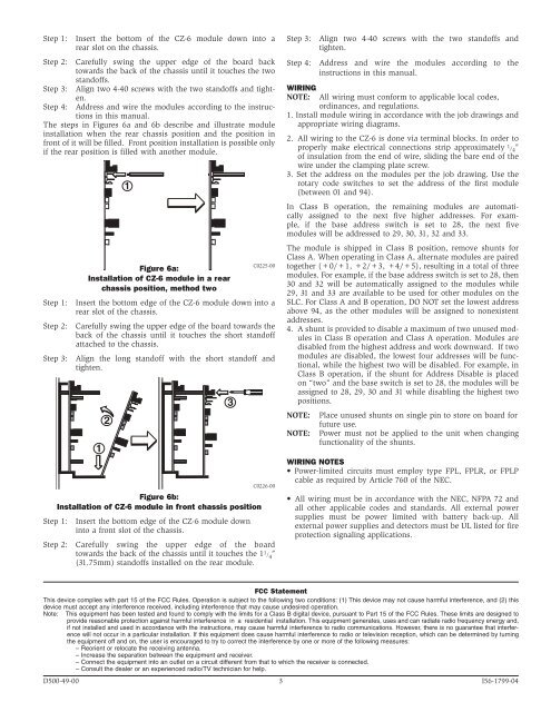
Step 1: Insert the bottom of the <strong>CZ</strong>-6 module down into arear slot on the chassis.Step 2: Carefully swing the upper edge of the board backtowards the back of the chassis until it touches the twostandoffs.Step 3: Align two 4-40 screws with the two standoffs and tighten.Step 4: Address and wire the modules according to the instructionsin this manual.The steps in Figures 6a and 6b describe and illustrate moduleinstallation when the rear chassis position and the position infront of it will be filled. Front position installation is possible onlyif the rear position is filled with another module.Figure 6a:Installation of <strong>CZ</strong>-6 module in a rearchassis position, method twoStep 1: Insert the bottom edge of the <strong>CZ</strong>-6 module down into arear slot of the chassis.Step 2: Carefully swing the upper edge of the board towards theback of the chassis until it touches the short standoffattached to the chassis.Step 3: Align the long standoff with the short standoff andtighten.121Figure 6b:Installation of <strong>CZ</strong>-6 module in front chassis positionStep 1: Insert the bottom edge of the <strong>CZ</strong>-6 module downinto a front slot of the chassis.Step 2: Carefully swing the upper edge of the boardtowards the back of the chassis until it touches the 1 1 / 4″(31.75mm) standoffs installed on the rear module.3C0225-00C0226-00Step 3: Align two 4-40 screws with the two standoffs andtighten.Step 4: Address and wire the modules according to theinstructions in this manual.WIRINGNOTE:All wiring must conform to applicable local codes,ordinances, and regulations.1. Install module wiring in accordance with the job drawings andappropriate wiring diagrams.2. All wiring to the <strong>CZ</strong>-6 is done via terminal blocks. In order toproperly make electrical connections strip approximately 1 / 4 ″of insulation from the end of wire, sliding the bare end of thewire under the clamping plate screw.3. Set the address on the modules per the job drawing. Use therotary code switches to set the address of the first module(between 01 and 94).In Class B operation, the remaining modules are automaticallyassigned to the next five higher addresses. For example,if the base address switch is set to 28, the next fivemodules will be addressed to 29, 30, 31, 32 and 33.The module is shipped in Class B position, remove shunts forClass A. When operating in Class A, alternate modules are pairedtogether (+0/+1, +2/+3, +4/+5), resulting in a total of threemodules. For example, if the base address switch is set to 28, then30 and 32 will be automatically assigned to the modules while29, 31 and 33 are available to be used for other modules on theSLC. For Class A and B operation, DO NOT set the lowest addressabove 94, as the other modules will be assigned to nonexistentaddresses.4. A shunt is provided to disable a maximum of two unused modulesin Class B operation and Class A operation. <strong>Module</strong>s aredisabled from the highest address and work downward. If twomodules are disabled, the lowest four addresses will be functional,while the highest two will be disabled. For example, inClass B operation, if the shunt for Address Disable is placedon “two” and the base switch is set to 28, the modules will beassigned to 28, 29, 30 and 31 while disabling the highest twopositions.NOTE:NOTE:Place unused shunts on single pin to store on board forfuture use.Power must not be applied to the unit when changingfunctionality of the shunts.WIRING NOTES• Power-limited circuits must employ type FPL, FPLR, or FPLPcable as required by Article 760 of the NEC.• All wiring must be in accordance with the NEC, NFPA 72 andall other applicable codes and standards. All external powersupplies must be power limited with battery back-up. Allexternal power supplies and detectors must be UL listed for fireprotection signaling applications.FCC StatementThis device complies with part 15 of the FCC Rules. Operation is subject to the following two conditions: (1) This device may not cause harmful interference, and (2) thisdevice must accept any interference received, including interference that may cause undesired operation.Note: This equipment has been tested and found to comply with the limits for a Class B digital device, pursuant to Part 15 of the FCC Rules. These limits are designed toprovide reasonable protection against harmful interference in a residential installation. This equipment generates, uses and can radiate radio frequency energy and,if not installed and used in accordance with the instructions, may cause harmful interference to radio communications. However, there is no guarantee that interferencewill not occur in a particular installation. If this equipment does cause harmful interference to radio or television reception, which can be determined by turningthe equipment off and on, the user is encouraged to try to correct the interference by one or more of the following measures:– Reorient or relocate the receiving antenna.– Increase the separation between the equipment and receiver.– Connect the equipment into an outlet on a circuit different from that to which the receiver is connected.– Consult the dealer or an experienced radio/TV technician for help.D500-49-00 3 I56-1799-04