Clean-up Oscillator - TimeTech GmbH
Clean-up Oscillator - TimeTech GmbH
Clean-up Oscillator - TimeTech GmbH

Create successful ePaper yourself
Turn your PDF publications into a flip-book with our unique Google optimized e-Paper software.
Functions<br />
• Controlled by <strong>up</strong> to 5 ref. frequencies<br />
• Phase coherent fail-over<br />
• Averaging of the ref. frequencies.<br />
• Facility for constant, linear and for<br />
quadratic offset control<br />
• Very low phase noise BVA oscillator<br />
as internal frequency source<br />
• Clock ensembling improves the longterm<br />
frequency stability<br />
• On-line monitor of the input stability<br />
• Monitor data stored for postprocessing<br />
in an external PC<br />
• • File format compatible to STABLE32<br />
Copyright © 04/2006, <strong>TimeTech</strong> <strong>GmbH</strong><br />
Data subject to change without notice.<br />
04 April 2006<br />
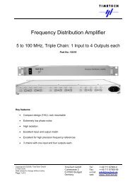
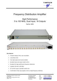
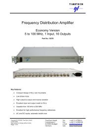
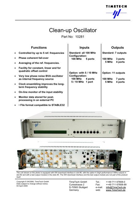
<strong>Clean</strong>-<strong>up</strong> <strong>Oscillator</strong><br />
Part No: 10281<br />
Inputs<br />
Standard: all 100 MHz<br />
Configuration:<br />
100 MHz 5 ports<br />
Option: with 5 / 10 MHz<br />
Configuration:<br />
100 MHz 4 ports<br />
5 / 10 MHz 1 port<br />
Outputs<br />
Standard: 7 outputs<br />
100 MHz 3 ports<br />
5 MHz 4 ports<br />
Option: 11 outputs<br />
100 MHz 7 ports<br />
5 MHz 4 ports<br />
The unit shown on the photo is equipped with SW download interface in slot #0, with the option 4 (high performance 5 MHz output) in<br />
slot #2 and with a test output module in the slots #3. The SW download interface and the test output module are not part of the product<br />
itself.<br />
<strong>TimeTech</strong> <strong>GmbH</strong> Tel.: ++49 711 67808-0<br />
Curiestrasse 2 Fax: ++49 711 67808-99<br />
D-70563 Stuttgart e-mail: info@<strong>TimeTech</strong>.de<br />
Germany web: www.<strong>TimeTech</strong>.de
<strong>Clean</strong>-<strong>up</strong> <strong>Oscillator</strong><br />
5 / 10 / 100 MHz ultra low phase noise clean-<strong>up</strong> oscillator<br />
Frequency offset and frequency drift compensation<br />
Part No: 10281<br />
<strong>Clean</strong>-<strong>up</strong> <strong>Oscillator</strong> front panel label and acronym in text: CLEAN<br />
Copyright © 04/2006, <strong>TimeTech</strong> <strong>GmbH</strong><br />
Data subject to change without notice.<br />
04 April 2006<br />
Page 2 of 11<br />
<strong>Clean</strong>-<strong>up</strong> <strong>Oscillator</strong> Applications<br />
I Phase noise clean-<strong>up</strong> with 100 MHz generation<br />
-80 dBc/Hz<br />
-100 dBc/Hz<br />
-106 dBc/Hz<br />
Phase noise<br />
Phase noise of 100 MHz generated from input<br />
without the CLEAN function<br />
5 MHz input signal phase noise (example)<br />
Offset frequency<br />
Improved phase<br />
noise output of the<br />
CLEAN<br />
13.10.2005 - PN_cleaning mw<br />
Phase noise over offset frequency, improvement by<br />
internal oscillator performance<br />
II Improving the ADEV stability<br />
5 x 10 -12<br />
1 x 10 -13<br />
ADEV<br />
ADEV improvement potential<br />
13.10.2005 - ADEV_improving mw<br />
Example input signal ADEV performance<br />
CLEAN internal oscillator performance<br />
10 ... 1000 sec<br />
Resulting ADEV performance<br />
of the CLEAN output signal<br />
Short term ADEV over tau, improvement by internal<br />
oscillator performance<br />
Tau<br />
The output frequency of commercial atomic clock<br />
equipment (e.g. Rubidium, Caesium, Hydrogen maser)<br />
is at 5 MHz, 10 MHz, or 100 MHz. Its phase noise is<br />
good, but it can even be improved by the CLEAN.<br />
Especially when generating 100 MHz clock reference<br />
signals (e. g. for reference input to <strong>up</strong>-converters) an<br />
excellent phase noise performance is essential<br />
because improving the phase noise of the reference<br />
signal directly improves the signal to noise ratio of the<br />
generated RF signal.<br />
The CLEAN generates a very low phase noise output<br />
at 100 MHz.<br />
The output frequency stability of commercial atomic<br />
clock equipment is very high in the long term, but in the<br />
short term further improvement is possible. The internal<br />
oscillator of the CLEAN provides enough short term<br />
stability for significantly improving the stability of a<br />
Cesium reference clock. This improves any time<br />
interval measurements <strong>up</strong> to time intervals of several<br />
100 seconds. As the improvement is achieved by the<br />
internal oscillator intrinsic phase stability performance<br />
the improvement factor depends on the stability of the<br />
reference input. Less stable input leads to a higher improvement factor. The time constant of the<br />
internal oscillator control loop can be adjusted for optimising the performance.<br />
III Clock ensemble monitoring<br />
Channel 1<br />
Channel 2<br />
Channel 3<br />
Channel 4<br />
Channel 5<br />
Reference<br />
PCO = Phase Comparator<br />
PCO<br />
PCO<br />
PCO<br />
PCO<br />
PCO<br />
Processor<br />
6<br />
ADEV<br />
- channel X vs. channel Y<br />
or<br />
- channel X vs. mean frequency output,<br />
evaluation in an external PC<br />
26.10.2005 -5Ch_monitor mw<br />
Phase measurement of 5 input channels, ADEV<br />
output for 6 channel combinations<br />
The outputs of a set of atomic clock equipment can be<br />
monitored against each other by means of a 5 channel<br />
phase comparator function of the CLEAN.<br />
The 5 phase comparators measure the phases of 5<br />
input signals versus a reference clock signal. The<br />
processor allows calculation of ADEV performance of<br />
any channel versus any other channel or of any<br />
channel versus the reference input. Normally the<br />
reference is the internal oscillator output, but the<br />
equipment allows for using an external reference as well (if controlling the internal oscillator is not<br />
required).<br />
<strong>TimeTech</strong> <strong>GmbH</strong> Tel.: ++49 711 67808-0<br />
Curiestrasse 2 Fax: ++49 711 67808-99<br />
D-70563 Stuttgart e-mail: info@<strong>TimeTech</strong>.de<br />
Germany web: www.<strong>TimeTech</strong>.de
<strong>Clean</strong>-<strong>up</strong> <strong>Oscillator</strong><br />
5 / 10 / 100 MHz ultra low phase noise clean-<strong>up</strong> oscillator<br />
Frequency offset and frequency drift compensation<br />
Part No: 10281<br />
IV Real time averaging of reference clocks<br />
Channel 1<br />
Channel 2<br />
Channel 3<br />
Channel 4<br />
Channel 5<br />
Reference<br />
PCO<br />
PCO<br />
PCO<br />
PCO<br />
PCO<br />
PCO = Phase Comparator<br />
D/A = Digital to Analog converter<br />
D/A<br />
Copyright © 04/2006, <strong>TimeTech</strong> <strong>GmbH</strong><br />
Data subject to change without notice.<br />
04 April 2006<br />
Page 3 of 11<br />
Processor<br />
Mean frequency output<br />
6<br />
ADEV<br />
- channel X vs. channel Y<br />
or<br />
- channel X vs. mean frequency output,<br />
evaluation in an external PC<br />
26.10.2005 -clock_ensemble mw<br />
Controlling the internal oscillator to the mean<br />
frequency of <strong>up</strong> to 5 input channels.<br />
ADEV<br />
Single input signal ADEV performance<br />
Long term ADEV<br />
improvement potential<br />
Tau<br />
26.10.2005 - Clock_ensemble ADEV mw<br />
Based on the monitoring function as described above<br />
the CLEAN can generate the mean frequency and<br />
phase of a clock ensemble in real time. The reference<br />
clock for the phase measurements is the CLEAN output<br />
signal.<br />
The averaging of the measured phase and frequency<br />
data for controlling the internal oscillator is done by the<br />
internal processor. The frequency generation function<br />
of the CLEAN is independent of the availability of any<br />
external computer.<br />
In the best case of 5 inputs of equal ADEV<br />
performance the improvement factor is SQRT(5) = 2.2.<br />
ADEV improvement by clock ensembling<br />
V Clock ageing compensation by micro-stepper function<br />
ADEV<br />
White frequency modulation<br />
~Tau -1/2<br />
Atomic clock ADEV behaviour<br />
Random walk frequency modulation<br />
Flicker frequency modulation<br />
~Tau 0<br />
CLEAN output with drift compensation<br />
~Tau +1/2<br />
Frequency drift<br />
Improvement potential by<br />
drift compensation<br />
13.10.2005 - drift_compensation mw<br />
Long term ADEV over tau, improvement by drift compensation<br />
~Tau +1<br />
Tau<br />
The CLEAN implements a micro<br />
stepper function. This allows for<br />
adding an arbitrary correction<br />
signal to the internal oscillator<br />
control signal. The clock model<br />
within the processor s<strong>up</strong>ports<br />
generating a phase offset, a<br />
frequency offset, and a frequency<br />
drift offset. These offsets can be<br />
generated for compensating<br />
corresponding offsets of the input<br />
channels individually for each<br />
channel.<br />
While the phase offset and the<br />
stationary frequency offset do not<br />
contribute to the ADEV the<br />
frequency drift offset does.<br />
Therefore, compensating this drift offset improves the ADEV of the CLEAN output in the long term.<br />
The drift value to be compensated can be measured by comparing the relevant input channel against the<br />
UTC (e. g. applying two-way time transfer from a suitable reference source) or, in case of a clock ensemble<br />
with non equally performing clocks, any worse performing input clock signal can be compared to the CLEAN<br />
output signal as the most stable reference of the site.<br />
<strong>TimeTech</strong> <strong>GmbH</strong> Tel.: ++49 711 67808-0<br />
Curiestrasse 2 Fax: ++49 711 67808-99<br />
D-70563 Stuttgart e-mail: info@<strong>TimeTech</strong>.de<br />
Germany web: www.<strong>TimeTech</strong>.de
<strong>Clean</strong>-<strong>up</strong> <strong>Oscillator</strong><br />
5 / 10 / 100 MHz ultra low phase noise clean-<strong>up</strong> oscillator<br />
Frequency offset and frequency drift compensation<br />
Part No: 10281<br />
VI Phase continuous switch over between several input sources<br />
100 MHz<br />
inputs<br />
13.10.2005 - switch_over mw<br />
PC<br />
5<br />
CLEAN<br />
PLL<br />
Copyright © 04/2006, <strong>TimeTech</strong> <strong>GmbH</strong><br />
Data subject to change without notice.<br />
04 April 2006<br />
Page 4 of 11<br />
1<br />
2<br />
offset generator<br />
dφ, df, df ∗ t<br />
+<br />
D / A<br />
phase measurement<br />
Display software<br />
Time offset
<strong>Clean</strong>-<strong>up</strong> <strong>Oscillator</strong><br />
5 / 10 / 100 MHz ultra low phase noise clean-<strong>up</strong> oscillator<br />
Frequency offset and frequency drift compensation<br />
Part No: 10281<br />
Copyright © 04/2006, <strong>TimeTech</strong> <strong>GmbH</strong><br />
Data subject to change without notice.<br />
04 April 2006<br />
Page 5 of 11<br />
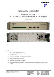
<strong>Clean</strong>-<strong>up</strong> <strong>Oscillator</strong> Modular Architecture<br />
Modular unit design<br />
The <strong>Clean</strong>-<strong>up</strong> <strong>Oscillator</strong> is a two height unit rack mountable unit consisting of <strong>up</strong> to 10 modules. The optional<br />
modules can be hot plugged without impacting the operation of the unit. Dedicated slots are carrying the<br />
essential modules such as the AC/DC Converter, the DC S<strong>up</strong>ply Module, the PC Module and the <strong>Oscillator</strong><br />
Module. All modules are mounted from the rear side. All signal inputs and outputs are also at the rear side.<br />
The CLEAN frame<br />
At its front panel the instrument has a LCD display and 8 push buttons for local control of the unit. LEDs on<br />
the front side show the over all alarm state (ERROR) of the unit, the DC power s<strong>up</strong>ply integrity and the<br />
remote control disabling (LOCAL).<br />
Modules providing the input ports<br />
The 5 external inputs at 100 MHz are at the PCO module This module is an assembly occ<strong>up</strong>ying three slots<br />
of the CLEAN frame.<br />
With the option #2 one input at 5 or 10 MHz is made available by adding a multiplier module. The output of<br />
this module is connected to an input channel of the PCO by an external patch cable.<br />
Modules providing the output ports<br />
The CLEAN product has the following output signal types<br />
• Multiplier module: 100 MHz, 4 outputs. One of these 4 outputs is needed for reference input to the<br />
phase comparator module, 3 of the outputs are usable externally.<br />
• <strong>Oscillator</strong> module: 5 MHz, 4 outputs at BNC connectors for standard performance applications<br />
• 100 MHz distributor module: 4 outputs at SMA connectors for high performance applications<br />
(option 1)<br />
• 5 MHz distributor module:, 4 outputs at SMA connectors for high performance applications<br />
(option 3)<br />
Internal oscillator<br />
The product is equipped with a high stability low phase noise 5 MHz crystal oscillator (BVA-OCXO) for<br />
internal frequency generation.<br />
Included Peripheral Equipment<br />
• Hirschmann Stak 20 connector for self cable mounting for connection to the Stakei 2 DC connector<br />
at the unit,<br />
• AC s<strong>up</strong>ply cord.<br />
• Serial interface cable<br />
Standard CLEAN Module Configuration<br />
Slot 0 Slot 1 Slot 2 Slot 3 Slot 4 Slot 5 Slot 6 Slot 7 Slot 8 Slot 9 Slot 10<br />
<strong>Oscillator</strong><br />
Module<br />
5 MHz<br />
Option slot Option slot Multiplier<br />
Module<br />
100 MHz<br />
1 output ><br />
+ 3 outputs<br />
PCO<br />
Module<br />
100 MHz<br />
< 1 input<br />
+ 5 inputs<br />
PCO<br />
Module<br />
PCO<br />
Module<br />
PC<br />
module<br />
DC/DC<br />
Power<br />
AC/DC<br />
Power<br />
4 outputs<br />
Input Input<br />
BNC<br />
SMA SMA<br />
18-32 V 90-265 V<br />
NOTE: One output of the multiplier module is connected by patch cable to one input of the PCO module<br />
(internal reference frequency). The remaining 3 outputs of the multiplier module (100 MHz being derived<br />
from the internal oscillator 5 MHz) can be used externally. The remaining 5 inputs of the PCO module can be<br />
used for feeding 100 MHz reference signals to the CLEAN. The product delivery comprises the required<br />
number of patch cables with a 6 dB attenuator each for making the Multiplier Module output signal<br />
compatible to the needs of the PCO Module input needs.<br />
Each of the options 1 to 3 (for the options see “Product Configurations” below) needs an option slot. Up to<br />
two options can simultaneously be implemented using the both option slots.<br />
<strong>TimeTech</strong> <strong>GmbH</strong> Tel.: ++49 711 67808-0<br />
Curiestrasse 2 Fax: ++49 711 67808-99<br />
D-70563 Stuttgart e-mail: info@<strong>TimeTech</strong>.de<br />
Germany web: www.<strong>TimeTech</strong>.de
<strong>Clean</strong>-<strong>up</strong> <strong>Oscillator</strong><br />
5 / 10 / 100 MHz ultra low phase noise clean-<strong>up</strong> oscillator<br />
Frequency offset and frequency drift compensation<br />
Part No: 10281<br />
External Visualisation / Display Software<br />
Copyright © 04/2006, <strong>TimeTech</strong> <strong>GmbH</strong><br />
Data subject to change without notice.<br />
04 April 2006<br />
Page 6 of 11<br />
The display software is used to<br />
monitor the integrity of the on–<br />
going measurements. It shows the<br />
current phase measurement data<br />
(“Statistical Channel”) and the<br />
current ADEV values for tau = 1<br />
sec as a plot over time based on a<br />
sliding window analysis of the<br />
received measurement data<br />
(“Running Allan Deviation”).<br />
Furthermore it presents tables of<br />
the current ADEV, the minimum<br />
ADEV and the maximum ADEV<br />
being calculated in the sliding<br />
window analysis since start of the<br />
measurement for tau = 1 .. 100 sec.<br />
In addition, the frequency (‘drift’) is<br />
given.<br />
This data is continuously provided<br />
for each of the five channels.<br />
Any combination of channels (sum,<br />
difference) can be selected as a<br />
‘virtual channel’ as well. For this<br />
channel, also ADEV and frequency<br />
offset is calculated and displayed.<br />
The following screen shot shows<br />
the summary screen of the display<br />
software.<br />
It gives the Allan Deviation for tau =<br />
1 to100 000 sec.<br />
The number given below the<br />
headline (“Channel x”) gives the<br />
number of phase samples being<br />
analyzed. Current measurement<br />
values are given for both time<br />
interval counters, the low resolution<br />
one (“LoRes Pha[ps]”) and the high<br />
resolution one (“HiRes Pha[ps]”).<br />
Furthermore the current frequency<br />
offset is given (“Drift[ps/s]”). The<br />
beat note (“Beat Freq[Hz]”) allows<br />
the expert checking the integrity of<br />
the phase measurement functions.<br />
Also ‘virtual channels’ can be<br />
monitored, here the 6 th table gives<br />
the difference between channel 1<br />
and channel 2.<br />
<strong>TimeTech</strong> <strong>GmbH</strong> Tel.: ++49 711 67808-0<br />
Curiestrasse 2 Fax: ++49 711 67808-99<br />
D-70563 Stuttgart e-mail: info@<strong>TimeTech</strong>.de<br />
Germany web: www.<strong>TimeTech</strong>.de
<strong>Clean</strong>-<strong>up</strong> <strong>Oscillator</strong><br />
5 / 10 / 100 MHz ultra low phase noise clean-<strong>up</strong> oscillator<br />
Frequency offset and frequency drift compensation<br />
Part No: 10281<br />
Copyright © 04/2006, <strong>TimeTech</strong> <strong>GmbH</strong><br />
Data subject to change without notice.<br />
04 April 2006<br />
Page 7 of 11<br />
Measurement Results<br />
A CLEAN Intrinsic Frequency Stability Performance<br />
Maser<br />
10.01.2006- ADEV<br />
measurement mw<br />
B CLEAN Intrinsic Phase Noise Performance<br />
Maser<br />
10.01.2006- PN<br />
measurement mw<br />
100 MHz<br />
100 MHz<br />
CLEAN<br />
Phase<br />
comparator<br />
100 MHz 100 MHz<br />
CLEAN<br />
100 MHz<br />
CLEAN<br />
C CLEAN switch-over phase response<br />
ADEV<br />
Analogue<br />
mixer<br />
FFT<br />
The graph shows the typical ADEV<br />
performance of the CLEAN.<br />
The measurement had been taken in air<br />
conditioned environment with a<br />
maximum temperature variation of < 0.5<br />
Kpp. The CLEAN <strong>Oscillator</strong> and an<br />
external phase comparator were locked<br />
to a common source with a passive<br />
splitter.<br />
The time constant of the CLEAN’s<br />
internal PLL is around 0.6 second by<br />
default. It is adjustable in order to allow<br />
for optimal filtering of the input signal.<br />
Above this time constant, the ADEV<br />
drops with a slope of –1 per decade over<br />
tau.<br />
The phase noise<br />
measurement is made<br />
by comparing two 100<br />
MHz outputs of two<br />
different CLEANs<br />
against each other by<br />
means of an analogue<br />
mixer and by FFT<br />
processing the low<br />
frequency output of that<br />
mixer. The phase noise<br />
performance of a single<br />
output is approximately<br />
obtained by subtracting<br />
3 dB from this<br />
measurement result.<br />
In the following measurement one of the input<br />
reference signals to the CLEAN <strong>Oscillator</strong> had been<br />
removed while the phase of the CLEAN output signal<br />
is recorded versus the phase of the stable<br />
measurement reference signal. The resulting phase<br />
transient of 1 ps phase step is shown in the screen<br />
shot below.<br />
<strong>TimeTech</strong> <strong>GmbH</strong> Tel.: ++49 711 67808-0<br />
Curiestrasse 2 Fax: ++49 711 67808-99<br />
D-70563 Stuttgart e-mail: info@<strong>TimeTech</strong>.de<br />
Germany web: www.<strong>TimeTech</strong>.de
<strong>Clean</strong>-<strong>up</strong> <strong>Oscillator</strong><br />
5 / 10 / 100 MHz ultra low phase noise clean-<strong>up</strong> oscillator<br />
Frequency offset and frequency drift compensation<br />
Part No: 10281<br />
Copyright © 04/2006, <strong>TimeTech</strong> <strong>GmbH</strong><br />
Data subject to change without notice.<br />
04 April 2006<br />
Page 8 of 11<br />
Controlling the <strong>Clean</strong>-<strong>up</strong> <strong>Oscillator</strong><br />
Local Control<br />
The <strong>Clean</strong>-<strong>up</strong> <strong>Oscillator</strong> front panel has a 2 lines 40 characters LCD display and 8 push buttons. This<br />
interface allows local control and monitoring of the unit. Especially the IP address of the unit is set via this<br />
interface.<br />
Remote Control by Telnet<br />
The <strong>Clean</strong>-<strong>up</strong> <strong>Oscillator</strong> allows for remote control via telnet using its TCP/IP port #23.<br />
TCP Command & Data Output Interface, and Serial Interface<br />
The <strong>Clean</strong>-<strong>up</strong> <strong>Oscillator</strong> s<strong>up</strong>ports a management and control interface (M&C) on its TCP/IP ports #2000 and<br />
#2001. The same function is also available via a serial RS232 interface. Regularly issued status reports as<br />
well as status reports on request are provided. For the data being available for such state reports see the list<br />
of monitored parameters below.<br />
UDP Interface<br />
The state reports can be made available also at UDP ports. This allows any external station monitor for<br />
getting the CLEAN state just by listening to this port.<br />
Functional <strong>up</strong>grades<br />
Firmware <strong>up</strong>grade is possible by FTP download.<br />
Configurable Parameters<br />
The following parameters can be configured either via Local Control or via Telnet.<br />
Function Configurable Parameter<br />
<strong>Oscillator</strong><br />
and<br />
control<br />
loop<br />
- Select input reference signal<br />
- Enable/disable the control loop<br />
(tracking/holdover)<br />
- Control loop time constant<br />
- Phase offset<br />
- Frequency offset<br />
- Frequency drift<br />
(all offsets versus the input reference)<br />
Function Configurable Parameter<br />
Input - Set 5 or 10 MHz input<br />
(option 2, see below)<br />
M&C - Save interval<br />
(time interval of regular state reports)<br />
- Clear system event record<br />
LAN - TCP/IP configuration<br />
- Remote control enable/disable<br />
- Telnet connection enable/disable<br />
Monitored Parameters<br />
The <strong>Clean</strong>-<strong>up</strong> <strong>Oscillator</strong> monitors all essential states of its internal hardware as well as the states of the<br />
inputs signals, the states of the output signals, the state of the internal oscillator control loop, and the states<br />
of the time interval counters.<br />
Function Monitored Parameters<br />
Hardware - Internal DC voltages<br />
- Internal currents<br />
- Unit internal temperature<br />
Outputs - Signal power<br />
Function Monitored Parameters<br />
<strong>Oscillator</strong> - Control loop offset and status<br />
PCO - Phase comparator current values<br />
- Measurement history<br />
<strong>TimeTech</strong> <strong>GmbH</strong> Tel.: ++49 711 67808-0<br />
Curiestrasse 2 Fax: ++49 711 67808-99<br />
D-70563 Stuttgart e-mail: info@<strong>TimeTech</strong>.de<br />
Germany web: www.<strong>TimeTech</strong>.de
<strong>Clean</strong>-<strong>up</strong> <strong>Oscillator</strong><br />
5 / 10 / 100 MHz ultra low phase noise clean-<strong>up</strong> oscillator<br />
Frequency offset and frequency drift compensation<br />
Part No: 10281<br />
Standard<br />
Option 1<br />
Option 2<br />
Option 3<br />
100 MHz<br />
inputs<br />
26.10.2005 - Basic mw<br />
100 MHz<br />
inputs<br />
26.10.2005 - Option 1 mw<br />
100 MHz<br />
inputs<br />
5 / 10 MHz<br />
input<br />
26.10.2005 - Option 2 mw<br />
100 MHz<br />
inputs<br />
09.01.2006 - Option 3 mw<br />
Copyright © 04/2006, <strong>TimeTech</strong> <strong>GmbH</strong><br />
Data subject to change without notice.<br />
04 April 2006<br />
Page 9 of 11<br />
Product configurations and options<br />
PCO Processor<br />
PCO Processor<br />
PCO Processor<br />
PCO Processor<br />
BVA<br />
OCXO<br />
BVA<br />
OCXO<br />
external cable<br />
BVA<br />
OCXO<br />
BVA<br />
OCXO<br />
external cable<br />
X 20<br />
external cable<br />
X 20<br />
X 20<br />
external cables<br />
X 20 / 10<br />
X 20<br />
5 MHz<br />
outputs<br />
100 MHz<br />
outputs<br />
to control loop<br />
5 MHz<br />
outputs<br />
100 MHz<br />
outputs<br />
to control loop<br />
100 MHz<br />
outputs<br />
5 MHz<br />
outputs<br />
100 MHz<br />
outputs<br />
to control loop<br />
no<br />
connectors<br />
equipped<br />
5 MHz<br />
outputs<br />
(BNC)<br />
100 MHz<br />
outputs<br />
to control loop<br />
5 MHz<br />
outputs<br />
(SMA)<br />
5 inputs at 100 MHz (SMA)<br />
3 outputs at 100 MHz (SMA)<br />
4 outputs at 5 MHz (BNC).<br />
Additional 4 outputs at 100 MHz.<br />
Total:<br />
5 inputs at 100 MHz (SMA)<br />
7 outputs at 100 MHz (SMA)<br />
4 outputs at 5 MHz (BNC)<br />
100 MHz Distribution module in<br />
option slot (4 outputs).<br />
One input at 5 or 10 MHz (configurable)<br />
replacing one 100 MHz input.<br />
Total:<br />
4 inputs at 100 MHz (SMA)<br />
1 input at 5 or 10 MHz (SMA)<br />
3 outputs at 100 MHz (SMA)<br />
4 outputs at 5 MHz (BNC)<br />
Multiplier module in option slot<br />
(1 input 5 / 10 MHz and 1 output 100<br />
MHz, patch cable from the output to one<br />
of the inputs of the PCO module).<br />
High performance 5 MHz output<br />
Total:<br />
5 inputs at 100 MHz (SMA)<br />
3 outputs at 100 MHz (SMA)<br />
4 outputs at 5 MHz (BNC)<br />
4 outputs at 5 MHz (SMA) high<br />
performance<br />
Option 4 A second DC input module instead of the AC input module in slot #10.<br />
5 MHz Distribution module in option slot<br />
(4 outputs).<br />
<strong>TimeTech</strong> <strong>GmbH</strong> Tel.: ++49 711 67808-0<br />
Curiestrasse 2 Fax: ++49 711 67808-99<br />
D-70563 Stuttgart e-mail: info@<strong>TimeTech</strong>.de<br />
Germany web: www.<strong>TimeTech</strong>.de
<strong>Clean</strong>-<strong>up</strong> <strong>Oscillator</strong><br />
5 / 10 / 100 MHz ultra low phase noise clean-<strong>up</strong> oscillator<br />
Frequency offset and frequency drift compensation<br />
Part No: 10281<br />
Copyright © 04/2006, <strong>TimeTech</strong> <strong>GmbH</strong><br />
Data subject to change without notice.<br />
04 April 2006<br />
Page 10 of 11<br />
Internal <strong>Oscillator</strong> Performance Specification<br />
Stability Performance ADEV Phase noise @ 5 MHz dBc/Hz<br />
Tau 1) 1 sec 1.3 * 10 -13 1 Hz -125<br />
3 sec 8.0 * 10 -14 10 Hz -145<br />
30 sec 8.0 * 10 -14 100 Hz -153<br />
1 kHz -156<br />
10 kHz -156<br />
Aging Spec 2 * 10 -11<br />
Typical 1 * 10 -11 per day after 30 days of continuous operation<br />
Intrinsic Stability and Phase Noise Performance<br />
The following tables give the intrinsic frequency stability and the intrinsic phase noise performance<br />
of the CLEAN when using the 100 MHz inputs and outputs.<br />
ADEV *)<br />
100 MHz<br />
dBc/Hz<br />
100 MHz<br />
Tau 1) spec typ Freq. Offset spec typ<br />
1 sec 1) 1.0 * 10 -13 7.9 * 10 -14 1 Hz -100 -101<br />
10 sec 1) 1.5 * 10 -14 1.1 * 10 -14 10 Hz -115 -117<br />
100 sec 1) 1.5 * 10 -15 1.2 * 10 -15 100 Hz -127 -129<br />
1 000 sec 1) 1.5 * 10 -16 1.3 * 10 -16 1 kHz -147 -153<br />
10 000 sec 1) 2.5 * 10 -17 1.8 * 10 -17 10 kHz -152 -158<br />
100 000 sec 1) 100 kHz -153 -159<br />
Notes<br />
*: ADEV here is the ADEV over the PLL error signal of the clean. In the long run, the CLEAN output is locked to the input<br />
signal. In the short run, the CLEAN output removes fluctuations of the input signal. Depending on the quality of the input<br />
signal, the loop bandwidth of the digital PLL has to be optimised, which affects the ADEV of the PLL’s error signal.<br />
1: Measurements at these time intervals depend heavily on external temperatures. Specified values are guaranteed only<br />
in thermally controlled laboratory environment (+18 to +24°C, slopes < 0.2K/h, variation
<strong>Clean</strong>-<strong>up</strong> <strong>Oscillator</strong><br />
5 / 10 / 100 MHz ultra low phase noise clean-<strong>up</strong> oscillator<br />
Frequency offset and frequency drift compensation<br />
Part No: 10281<br />
100 MHz Input<br />
Impedance 50 Ω Connector SMA<br />
Input Level +0 .. +7 dBm Frequency 100 MHz, sine wave<br />
.. for optimal performance +5 .. +7 dBm Frequency offset < 1 * 10 -12<br />
Copyright © 04/2006, <strong>TimeTech</strong> <strong>GmbH</strong><br />
Data subject to change without notice.<br />
04 April 2006<br />
Page 11 of 11<br />
.. operational < 5 * 10 -10<br />
5 / 10 MHz Input (option)<br />
Impedance 50 Ω Connector SMA<br />
Input Level +3 .. + 15 dBm Frequency 5 / 10 MHz, sine wave<br />
.. for optimal performance +7 .. + 15 dBm Frequency configuration Manual configuration<br />
Frequency offset < 1 * 10 -12<br />
.. operational < 5 * 10 -10<br />
100 MHz Output<br />
Impedance 50 Ω Connector SMA<br />
Output Level +11.5 ± 0.5 dBm Frequency 100 MHz, sine wave<br />
5 MHz Output (standard performance)<br />
Impedance 50 Ω Connector BNC<br />
Output Level +12.5 ± 0.5 dBm Frequency 5 MHz, sine wave<br />
5 MHz Output (high performance, option)<br />
Impedance 50 Ω Connector SMA<br />
Output Level +12.5 ± 0.5 dBm Frequency 5 MHz, sine wave<br />
Electrical interface<br />
S<strong>up</strong>ply voltage DC 18 to 32 V DC<br />
S<strong>up</strong>ply voltage AC 90 to 265 V AC, 47 to 65 Hz<br />
Source selection Load sharing between AC and DC inputs<br />
Power Consumption < 60 watts<br />
M & C interface<br />
Serial line RS232, 9 pin Sub-D male connector<br />
Protocol 19200 bps 8N1, plain ASCII<br />
Availability If not used for time code input or output.<br />
Ethernet 10 Mbit/s twisted pair, RJ45 connector<br />
Service Port Service Port<br />
TCP services Telnetd 23 Data output 2001<br />
Command 2000<br />
UDP services Syslog client 514 Data output configurable<br />
TFTP server 69 NTP client 123<br />
Monitored items ADEV, phase, frequency, PLL lock state, instrument status & control<br />
Commandable items Measurement start, stop, clear<br />
Definition of the offset control signal<br />
Front display<br />
With the option 4 the device is equipped with<br />
redundant (double) DC input and no AC input.<br />
LCD display, 2 lines, 80 characters<br />
Monitor display per channel: signal presence + phase and frequency offset versus the<br />
reference channel.<br />
8 push buttons for basic instrument set<strong>up</strong> and configuration.<br />
Mechanical<br />
Outline, Weight 19 inch, 2 height units (448.8 mm ∗ 88 mm)<br />
depth 448 mm, weight 8 kg.<br />
Environmental<br />
Transportation and Storage Operation<br />
Temperature. -20°C to +75°C Temperature<br />
Humidity 10% to 90% (non condensing)<br />
0°C to +40°C<br />
(spec. valid for +18..+24°C, ±1 Kpp, slope < 0.2K/h)<br />
Altitude < 20 000 m Humidity 20% to 90% (non condensing)<br />
Shock max 10g acceleration for 11 ms Altitude < 3 000 m<br />
Vibration max. 0.15 mm at 5 to 8 Hz,<br />
max 1g acceleration at 8 to 500 Hz<br />
<strong>TimeTech</strong> <strong>GmbH</strong> Tel.: ++49 711 67808-0<br />
Curiestrasse 2 Fax: ++49 711 67808-99<br />
D-70563 Stuttgart e-mail: info@<strong>TimeTech</strong>.de<br />
Germany web: www.<strong>TimeTech</strong>.de