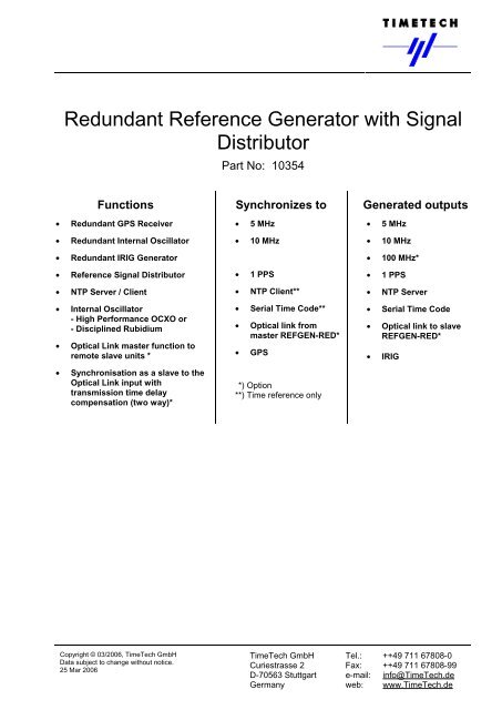
Redundant Reference Generator with Signal ... - TimeTech GmbH
Redundant Reference Generator with Signal ... - TimeTech GmbH
Redundant Reference Generator with Signal ... - TimeTech GmbH

Create successful ePaper yourself
Turn your PDF publications into a flip-book with our unique Google optimized e-Paper software.
<strong>Redundant</strong> <strong>Reference</strong> <strong>Generator</strong> <strong>with</strong> <strong>Signal</strong><br />
Distributor<br />
Functions<br />
• <strong>Redundant</strong> GPS Receiver<br />
• <strong>Redundant</strong> Internal Oscillator<br />
• <strong>Redundant</strong> IRIG <strong>Generator</strong><br />
• <strong>Reference</strong> <strong>Signal</strong> Distributor<br />
• NTP Server / Client<br />
• Internal Oscillator<br />
- High Performance OCXO or<br />
- Disciplined Rubidium<br />
• Optical Link master function to<br />
remote slave units *<br />
• Synchronisation as a slave to the<br />
Optical Link input <strong>with</strong><br />
transmission time delay<br />
compensation (two way)*<br />
Copyright © 03/2006, <strong>TimeTech</strong> <strong>GmbH</strong><br />
Data subject to change <strong>with</strong>out notice.<br />
25 Mar 2006<br />
Part No: 10354<br />
Synchronizes to<br />
• 5 MHz<br />
• 10 MHz<br />
• 1 PPS<br />
• NTP Client**<br />
• Serial Time Code**<br />
• Optical link from<br />
master REFGEN-RED*<br />
• GPS<br />
**) Option<br />
**) Time reference only<br />
Generated outputs<br />
• 5 MHz<br />
• 10 MHz<br />
• 100 MHz*<br />
• 1 PPS<br />
• NTP Server<br />
• Serial Time Code<br />
• Optical link to slave<br />
REFGEN-RED*<br />
• IRIG<br />
<strong>TimeTech</strong> <strong>GmbH</strong> Tel.: ++49 711 67808-0<br />
Curiestrasse 2 Fax: ++49 711 67808-99<br />
D-70563 Stuttgart e-mail: info@<strong>TimeTech</strong>.de<br />
Germany web: www.<strong>TimeTech</strong>.de
<strong>Redundant</strong> <strong>Reference</strong> <strong>Generator</strong><br />
REFGEN RED 10354<br />
5 / 10 MHz, 1 PPS, IRIG, GPS receiver, NTP server<br />
Copyright © 03/2006, <strong>TimeTech</strong> <strong>GmbH</strong><br />
Data subject to change <strong>with</strong>out notice.<br />
25 Mar 2006<br />
Page 2 of 13<br />
Redundancy Features<br />
The <strong>Redundant</strong> <strong>Reference</strong> <strong>Generator</strong> <strong>with</strong> <strong>Signal</strong> Distributor (REFGEN-RED) is a generator for<br />
generating frequency, pulse and time code reference signals from the GPS reference and for distributing<br />
these signals on a large number of output ports.<br />
These functions of the REFGEN-RED are highly available due to the redundant implementation of all<br />
essential functions of the unit. In particular these are<br />
• The GPS receiver<br />
• The internal oscillator<br />
• The IRIG generator<br />
• The power supply<br />
The redundancy functions are implemented such that the system can seamlessly change the active / standby<br />
roles of these redundant modules. The redundant power supply implements the load sharing principle<br />
instead of the active / stand-by roles.<br />
29.12.2005 - 10354 - RED 1<br />
GPS<br />
Receiver<br />
PLL<br />
GPS<br />
Receiver PLL<br />
Figure 1: REFGEN-RED redundancy architecture<br />
frequency & 1 PPS<br />
Time Code<br />
IRIG Gen<br />
IRIG Gen<br />
The diagram above shows the redundancy architecture of the REFGEN-RED. One of the both GPS receiver<br />
outputs is selected as the active one while the other one is standby. The active GPS output is the time and<br />
frequency reference for the REFGEN-RED to generate all internally used reference signals from. It<br />
synchronises the PLL of the internal oscillator at 10 MHz and the generation of the 1 PPS internal time<br />
reference. One of the redundant oscillators is the master being locked to the GPS reference and the other<br />
one is the slave being locked to the output of the master oscillator. The frequency and pulse distribution<br />
modules can select either of the both oscillator outputs. In order to maintain coherence of all output signals<br />
even in case of internal failures the selectors of all output signal distributor modules are aligned selecting the<br />
same source. The same applies to the IRIG generator input signal selector and to the IRIG distributor<br />
module selectors.<br />
Oscillator control by GPS<br />
One of the both oscillator modules is active playing the synchronisation master role. Normally the master<br />
oscillator is synchronized to the 1 PPS output of the active GPS receiver. The synchronisation control loop<br />
implements a rather great time constant in order to effectively filter the jitter being inherent to the GPS<br />
<strong>TimeTech</strong> <strong>GmbH</strong> Tel.: ++49 711 67808-0<br />
Curiestrasse 2 Fax: ++49 711 67808-99<br />
D-70563 Stuttgart e-mail: info@<strong>TimeTech</strong>.de<br />
Germany web: www.<strong>TimeTech</strong>.de
<strong>Redundant</strong> <strong>Reference</strong> <strong>Generator</strong><br />
REFGEN RED 10354<br />
5 / 10 MHz, 1 PPS, IRIG, GPS receiver, NTP server<br />
receiver output signal. The master oscillator generates high stability frequency and 1 PPS signals for feeding<br />
the signal distribution modules and for providing a synchronisation reference to the second, i. e. the slave,<br />
oscillator.<br />
The oscillator control loop can be disabled, e. g. for maintenance purposes. Then the oscillator is operating<br />
in the holdover mode freezing the current oscillator frequency. ’Manual’ tuning of the oscillator is possible via<br />
a 24 bit DAC.<br />
The second oscillator is the slave oscillator that is synchronised to the output of the master oscillator. This<br />
slaving is done <strong>with</strong> a fast control loop that guaranties a very stable and accurate phase alignment between<br />
the master and the slave output signals. This is important for the moment at which the distribution modules<br />
are commanded to change their internal redundant input signal selection. The accurate phase alignment<br />
causes the switch over to be performed <strong>with</strong>out phase hit.<br />
The both GPS receivers are continuously monitored for their GPS satellite tracking performance. That GPS<br />
receiver which has the better tracking performance is declared to be the active GPS receiver. The output of<br />
this GPS receiver is used for controlling the master oscillator of the REFGEN-RED. When the GPS tracking<br />
performance changes between the both GPS receivers, after some waiting time, the “active” and “stand-by”<br />
attributes for the both receivers are interchanged and the oscillator is controlled by the output of the other<br />
GPS receiver. This change of the reference is seamless.<br />
Both automatic processes, the active GPS receiver setting and the master/slave oscillator setting, can be<br />
overruled by manual interaction. This manual override is needed for preparing the REFGEN-RED for<br />
maintenance actions. The stand-by GPS receiver (if it is the GPS-2) and the slave oscillator module can be<br />
removed <strong>with</strong>out impact on the performance of the REFGEN-RED. The GPS-1 is on the PC module. Thus<br />
removing this causes the oscillator control to be removed as well. For such maintenance action the master<br />
oscillator needs to be set to holdover mode first.<br />
Oscillator control by 1 PPS or frequency input<br />
The REFGEN-RED provides two inputs of 1 PPS and one frequency input. The frequency input has<br />
automatic detection capability to distinguish 5 MHz and 10 MHz. These inputs can be used to synchronise<br />
the REFGEN-RED.<br />
Oscillator master / slave setting<br />
On start-up of the REFGEN-RED one of the both oscillators becomes the master. Once an oscillator module<br />
on start-up finds an active master oscillator being present it will become the slave. The master / slave setting<br />
changes automatically in case the master oscillator reports any failure or in case the master reference signal<br />
to the slave fails.<br />
<strong>Reference</strong> signal generation and distribution<br />
The oscillator module generates the frequency reference and the 1 PPS reference for signal distribution. The<br />
internal reference outputs of the both oscillator modules are connected to the distribution modules and to the<br />
both IRIG generator modules. These modules select the reference signal of the master oscillator. In case of<br />
failure or in case of manual maintenance command to the REFGEN-RED the slave reference signal will be<br />
selected. Such switch-over is controlled and synchronised by the PC module in order to ensure the<br />
coherency of all the output signals.<br />
Time code Generation and Outputs<br />
The REFGEN has a redundant IRIG code generator that can generate simultaneously two selected time<br />
codes of the following list of codes: IRIG-A, -B, -D, -E; -G, -H; NASA-36, IRIG B 5 MHz. These codes are<br />
internally distributed via 4 IRIG channels. In addition to the internal distribution of the IRIG channels the IRIG<br />
generator provides 4 IRIG channels at external interfaces.<br />
Copyright © 03/2006, <strong>TimeTech</strong> <strong>GmbH</strong><br />
Data subject to change <strong>with</strong>out notice.<br />
25 Mar 2006<br />
Page 3 of 13<br />
<strong>TimeTech</strong> <strong>GmbH</strong> Tel.: ++49 711 67808-0<br />
Curiestrasse 2 Fax: ++49 711 67808-99<br />
D-70563 Stuttgart e-mail: info@<strong>TimeTech</strong>.de<br />
Germany web: www.<strong>TimeTech</strong>.de
<strong>Redundant</strong> <strong>Reference</strong> <strong>Generator</strong><br />
REFGEN RED 10354<br />
5 / 10 MHz, 1 PPS, IRIG, GPS receiver, NTP server<br />
Each IRIG distribution module can be configured for external distribution of one of the 4 IRIG channels on<br />
four connectors.<br />
The REFGEN-RED has two IRIG generators. Both are configured identically <strong>with</strong> respect to the IRIG codes<br />
being generated on the 4 IRIG channels and <strong>with</strong> respect to the selection of the frequency reference, the<br />
1 PPS reference (both from the same oscillator module) and the time reference (from the active GPS<br />
module). The internal outputs (the 4 IRIG channels) are distributed redundantly to the IRIG distributor<br />
modules. All distributor modules select their configured IRIG channel from the active GPS receiver.<br />
Protected and non-protected output signal types<br />
All output signals that are transmitted from a distribution module being able to select between two internal<br />
reference signals are called “protected” outputs since their function is protected against a hardware failure<br />
<strong>with</strong>in the REFGEN-RED. Protected outputs of 5 MHz, 10 MHz, 100 MHz (option), optical link (option),<br />
1 PPS and IRIG are provided.<br />
In addition to the protected outputs the REFGEN-RED has non-protected outputs from the generator<br />
modules, i. e. from the oscillator module and from the IRIG generator module.<br />
Copyright © 03/2006, <strong>TimeTech</strong> <strong>GmbH</strong><br />
Data subject to change <strong>with</strong>out notice.<br />
25 Mar 2006<br />
Page 4 of 13<br />
REFGEN-RED Applications<br />
The range of applications for the REFGEN-RED is the same as for the non-redundant REFGEN (product No<br />
10292). These applications are described below.<br />
I Standard GPS based Time & Frequency Generation<br />
15.12.2005 - Ap1 mw<br />
REFGEN<br />
LAN<br />
10 MHz<br />
5 MHz<br />
1 PPS<br />
IRIG<br />
NTP<br />
signal user<br />
II Intra-Building Distribution<br />
Room A<br />
Room B<br />
master slave<br />
REFGEN<br />
10.01.2006 - AP2 mw<br />
Frequency & 1 PPS<br />
10 MHz<br />
5 MHz<br />
1 PPS<br />
IRIG<br />
NTP<br />
signal user<br />
LAN<br />
REFGEN<br />
10 MHz<br />
5 MHz<br />
1 PPS<br />
IRIG<br />
NTP<br />
signal user<br />
• Generation of time code signals and standard frequency<br />
signals from the GPS reference.<br />
• The highly stable internal oscillator allows for extensive<br />
averaging of the GPS raw data for generating stable and<br />
low jitter output signals.<br />
• In case of loss of the GPS input the internal oscillator<br />
provides a stable holdover mode.<br />
• LAN interface for M&C purposes and for NTP server<br />
output.<br />
• Time and frequency is transferred to a slave unit<br />
in another room.<br />
• <strong>Reference</strong>s of frequency (5 or 10 MHz) and of<br />
1 PPS transmitted by coax cables to the slave<br />
unit.<br />
• Time tag is transferred to the remote site over the<br />
LAN via NTP.<br />
• Time offset between master and slave due to<br />
transmission delay.<br />
<strong>TimeTech</strong> <strong>GmbH</strong> Tel.: ++49 711 67808-0<br />
Curiestrasse 2 Fax: ++49 711 67808-99<br />
D-70563 Stuttgart e-mail: info@<strong>TimeTech</strong>.de<br />
Germany web: www.<strong>TimeTech</strong>.de
<strong>Redundant</strong> <strong>Reference</strong> <strong>Generator</strong><br />
REFGEN RED 10354<br />
5 / 10 MHz, 1 PPS, IRIG, GPS receiver, NTP server<br />
III Optical Link to remote site<br />
Site A<br />
Site B<br />
master slave<br />
REFGEN<br />
15.12.2005 - Ap3 mw<br />
LAN<br />
optical 2-way link<br />
10 MHz<br />
5 MHz<br />
1 PPS<br />
IRIG<br />
NTP<br />
signal user<br />
REFGEN<br />
Copyright © 03/2006, <strong>TimeTech</strong> <strong>GmbH</strong><br />
Data subject to change <strong>with</strong>out notice.<br />
25 Mar 2006<br />
Page 5 of 13<br />
10 MHz<br />
5 MHz<br />
1 PPS<br />
IRIG<br />
NTP<br />
remote site<br />
signal user<br />
Option 4 (optical 2-way interface) required.<br />
IV Distribution to a large number of sites<br />
master<br />
REFGEN<br />
Site A<br />
10.01.2006 - Ap7 mw<br />
10 MHz<br />
5 MHz<br />
1 PPS<br />
IRIG<br />
NTP<br />
LAN<br />
optical 2-way links,<br />
or electrical links<br />
slave +<br />
master<br />
REFGEN<br />
Site B<br />
10 MHz<br />
5 MHz<br />
1 PPS<br />
IRIG<br />
NTP<br />
slave<br />
REFGEN<br />
Site C<br />
Furhter distribution <strong>with</strong><br />
optical 2-way links,<br />
or <strong>with</strong> electrical links<br />
10 MHz<br />
5 MHz<br />
1 PPS<br />
IRIG<br />
NTP<br />
slave<br />
REFGEN<br />
Site F<br />
V Frequency input from external atomic clock & GPS time reference<br />
External frequency<br />
source,<br />
e. g. atomic clock<br />
15.12.2005 - Ap8 mw<br />
5 / 10<br />
MHz<br />
REFGEN<br />
LAN<br />
10 MHz<br />
5 MHz<br />
1 PPS<br />
IRIG<br />
NTP<br />
slave<br />
REFGEN<br />
Site D<br />
10 MHz<br />
5 MHz<br />
1 PPS<br />
IRIG<br />
NTP<br />
signal user<br />
10 MHz<br />
5 MHz<br />
1 PPS<br />
IRIG<br />
NTP<br />
slave<br />
REFGEN<br />
Site E<br />
• Time and frequency is transferred to a remote<br />
site over a distance of up to 2 km.<br />
• The transmission delay is dynamically<br />
compensated by the 2-way method. Standard<br />
optical cable can be used.<br />
• The optical link signal supports all: frequency,<br />
ambiguity resolution, time tag and maintenance<br />
signals.<br />
• Single 2-fiber optical cable interconnection. No<br />
LAN connection between the sites is required, not<br />
even for M&C of the remote site.<br />
10 MHz<br />
5 MHz<br />
1 PPS<br />
IRIG<br />
NTP<br />
The optical link interface provides 4 optical<br />
interfaces for connecting up to 4 remote slave<br />
REFGENs to a single master REFGEN.<br />
Alternatively and additionally electrical links can<br />
be used for slaving remote sites.<br />
Each slave REFGEN can act as a master for<br />
further distribution to further slave REFGENs.<br />
This allows for creating virtually an infinite<br />
network of REFGENs being located at individual<br />
sites.<br />
Option 4 (optical 2-way interface) provides the<br />
optical links if required.<br />
• An external frequency input is used for locking<br />
the internal oscillator and for generating the<br />
internal 1 PPS signal.<br />
• The 1 PPS signal and the time tag of the GPS<br />
input are used as time reference.<br />
Use this configuration<br />
• If the GPS reference is not stable enough to<br />
serve as frequency reference.<br />
• If the Rubidium option of the REFGEN doesn’t<br />
have sufficient long term stability.<br />
• If coherence to the external frequency source is<br />
required rather than coherence to GPS.<br />
<strong>TimeTech</strong> <strong>GmbH</strong> Tel.: ++49 711 67808-0<br />
Curiestrasse 2 Fax: ++49 711 67808-99<br />
D-70563 Stuttgart e-mail: info@<strong>TimeTech</strong>.de<br />
Germany web: www.<strong>TimeTech</strong>.de
<strong>Redundant</strong> <strong>Reference</strong> <strong>Generator</strong><br />
REFGEN RED 10354<br />
5 / 10 MHz, 1 PPS, IRIG, GPS receiver, NTP server<br />
VI Frequency input from external atomic clock & NTP time reference<br />
External frequency<br />
source,<br />
e. g. atomic clock<br />
15.12.2005 - Ap9 mw<br />
1 PPS<br />
5 / 10<br />
MHz<br />
REFGEN<br />
LAN<br />
10 MHz<br />
5 MHz<br />
1 PPS<br />
IRIG<br />
NTP<br />
VII Holdover mode operation<br />
15.12.2005 - Ap10 mw<br />
REFGEN<br />
LAN<br />
10 MHz<br />
5 MHz<br />
1 PPS<br />
IRIG<br />
NTP<br />
Copyright © 03/2006, <strong>TimeTech</strong> <strong>GmbH</strong><br />
Data subject to change <strong>with</strong>out notice.<br />
25 Mar 2006<br />
Page 6 of 13<br />
signal user<br />
signal user<br />
Frequency synchronisation functions<br />
external frequency input<br />
external 1 PPS input<br />
04.01.2006 - A1 mw<br />
GPS antenna<br />
optical link from master<br />
1<br />
2<br />
REFGEN<br />
GPS<br />
Receiver<br />
2<br />
1 PPS<br />
slave function<br />
1 PPS<br />
clock input<br />
selector<br />
1 PPS<br />
generator<br />
/monitor<br />
PLL<br />
: 2<br />
X 20<br />
• An external frequency input is used for locking<br />
the internal oscillator and for generating the<br />
internal 1 PPS signal.<br />
• The time tag of the NTP input is used as time<br />
reference on start-up.<br />
• The external source needs to supply a<br />
frequency reference and a 1 PPS signal to the<br />
REFGEN for start-up 1PPS alignment.<br />
Use this configuration<br />
• If the Rubidium option of the REFGEN doesn’t<br />
have sufficient long term stability.<br />
• If no GPS reference is available.<br />
<strong>Reference</strong> <strong>Generator</strong> Functions<br />
4 4<br />
2<br />
master function<br />
Time synchronisation functions<br />
GPS antenna<br />
optical link from master<br />
REFGEN<br />
GPS<br />
Receiver<br />
2<br />
NTP<br />
client<br />
time<br />
serial time<br />
code<br />
NTP<br />
server<br />
time input<br />
selector<br />
Time<br />
code<br />
generator<br />
1 PPS<br />
generator<br />
/monitor<br />
NTP input (LAN) Serial time code input (RS232)<br />
PLL<br />
04.01.2006 - A2 mw<br />
1 PPS<br />
outputs<br />
10 MHz<br />
outputs<br />
5 MHz<br />
outputs<br />
100 MHz<br />
outputs<br />
Option<br />
optical link interface<br />
Option<br />
NTP output (LAN)<br />
serial time code<br />
output (RS232)<br />
IRIG code #1 outputs<br />
IRIG code #2 outputs<br />
IRIG code #x outputs<br />
IRIG code #y outputs<br />
x,y = 1 or 2<br />
configurable<br />
• The internal oscillator is the active frequency<br />
source and the reference for generation of the<br />
internal 1 PPS signal.<br />
• The system time is continued from the previous<br />
synchronized state.<br />
• The system time can manually be set for test<br />
purposes.<br />
The REFGEN-RED can be configured to lock to one of<br />
the following input reference signals for frequency<br />
generation:<br />
• GPS 1 PPS<br />
• External frequency input 5 or 10 MHz<br />
• External 1 PPS input<br />
• Optical link from master REFGEN-RED (or nonredundant<br />
REFGEN).<br />
The REFGEN-RED can be configured to synchronise its<br />
internal time to one of these sources at start-up<br />
• GPS time reference<br />
• NTP time reference<br />
• Serial time code input<br />
• Optical link from master REFGEN-RED (or nonredundant<br />
REFGEN).<br />
• Manual time setting if no other input is available.<br />
System Time<br />
Normally the REFGEN-RED is synchronised to the time reference on start-up of the unit. Afterwards the<br />
internal system time is continued by dividing the output frequency of the internal oscillator. The system time<br />
<strong>TimeTech</strong> <strong>GmbH</strong> Tel.: ++49 711 67808-0<br />
Curiestrasse 2 Fax: ++49 711 67808-99<br />
D-70563 Stuttgart e-mail: info@<strong>TimeTech</strong>.de<br />
Germany web: www.<strong>TimeTech</strong>.de
<strong>Redundant</strong> <strong>Reference</strong> <strong>Generator</strong><br />
REFGEN RED 10354<br />
5 / 10 MHz, 1 PPS, IRIG, GPS receiver, NTP server<br />
is monitored against the defined time reference and an alarm is issued if the time offset exceeds the<br />
configured threshold.<br />
Time interval counting function<br />
The PC module of the unit has four time interval counters (TICs). In the normal synchronized mode two of<br />
these TICs are used for the control loops <strong>with</strong> the both oscillator modules. The remaining 2 TICs can be<br />
used for comparing selected input signals of 1 PPS or 10/5 MHz versus the active oscillator output e. g. for<br />
measurement purposes.<br />
NTP interface via TCP/IP<br />
The unit integrates a network interface (LAN) supporting TCP and UDP services. Thus the REFGEN-RED<br />
can act as NTP client or as NTP stratum 1 server.<br />
Serial time code output<br />
The serial interface can be programmed to output serial ASCII-style time codes.<br />
Included Peripheral Equipment<br />
• 2 active GPS antennae <strong>with</strong> cables (30m),<br />
• 2 Hirschmann Stak 20 connectors for self cable mounting for connection to the Stakei 2 DC<br />
connector at the unit,<br />
• 2 AC supply cords<br />
• 1 serial interface cable<br />
Copyright © 03/2006, <strong>TimeTech</strong> <strong>GmbH</strong><br />
Data subject to change <strong>with</strong>out notice.<br />
25 Mar 2006<br />
Page 7 of 13<br />
Controlling the <strong>Reference</strong> <strong>Generator</strong><br />
Local Control<br />
The <strong>Reference</strong>s <strong>Generator</strong> front panel has a 2 lines 40 characters LCD display and 8 push buttons. This<br />
interface allows local control and monitoring of the unit. Especially the IP address of the unit is set via this<br />
interface.<br />
Remote Control by Telnet<br />
The <strong>Reference</strong> <strong>Generator</strong> allows for remote control via telnet using its TCP/IP port #23.<br />
Alarm Relay<br />
An alarm relay output (contact closed on alarm condition) is provided. The alarm is active when a failure is<br />
detected that requires a maintenance action to be done.<br />
Configurable Parameters<br />
The following parameters can be configured either via Local Control or via Telnet. Individual configurations<br />
are possible for any type of output, i. e. all 5 MHz outputs show the same behaviour, but the configuration for<br />
the 5 MHz outputs and the 10 MHz outputs may be different.<br />
Function Configurable Parameter<br />
GPS - Mode of operation<br />
- Set active/standby GPS<br />
IRIG - Time code channel #n<br />
- Amplitude channel #n<br />
- Select channel #n for each distribution<br />
module<br />
(n = 1 .. 4)<br />
- Set active/standby IRIG generator<br />
1 PPS<br />
Outputs<br />
- Input signal trigger level individually for<br />
every interface<br />
- Output: amplitude (2 levels)<br />
- Enable/disable(mute)<br />
- Set time error threshold for<br />
enabling the output<br />
- Set auto-muting during holdover<br />
Function Configurable Parameter<br />
Oscillator - Enable/disable the control loop<br />
(tracking/holdover)<br />
- Regulation offset<br />
(time offset versus the input reference)<br />
- Change master/slave<br />
M&C<br />
LAN<br />
- Save interval<br />
(time interval of regular state reports)<br />
- Clear system event record<br />
- TCP/IP configuration<br />
- Remote control enable/disable<br />
- Telnet connection enable/disable<br />
<strong>TimeTech</strong> <strong>GmbH</strong> Tel.: ++49 711 67808-0<br />
Curiestrasse 2 Fax: ++49 711 67808-99<br />
D-70563 Stuttgart e-mail: info@<strong>TimeTech</strong>.de<br />
Germany web: www.<strong>TimeTech</strong>.de
<strong>Redundant</strong> <strong>Reference</strong> <strong>Generator</strong><br />
REFGEN RED 10354<br />
5 / 10 MHz, 1 PPS, IRIG, GPS receiver, NTP server<br />
TCP Command & Data Output Interface, and Serial Interface<br />
The <strong>Reference</strong>s <strong>Generator</strong> supports a management and control interface (M&C) on its TCP/IP ports #2000<br />
and #2001. The same function is also available via a serial RS232 interface. Regularly issued status reports<br />
as well as status reports on request are provided. For the data being available for such state reports see the<br />
list of monitored parameters below.<br />
UDP Interface<br />
The state reports can be made available also at UDP ports. This allows any external station controller for<br />
getting the REFGEN-RED state just by listening to this port.<br />
Monitored Parameters<br />
The <strong>Reference</strong> <strong>Generator</strong> monitors all essential states of its internal hardware as well as the states of the<br />
inputs signals, the states of the output signals, the state of the internal oscillator control loop, and the states<br />
of the time interval counters.<br />
Function Monitored Parameters<br />
Hardware - Internal DC voltages<br />
- Internal currents<br />
- Unit internal temperature<br />
Outputs - <strong>Signal</strong> power<br />
- <strong>Signal</strong> muted<br />
Oscillator<br />
- Control loop offset and status<br />
Supported IRIG codes and IRIG channels<br />
Copyright © 03/2006, <strong>TimeTech</strong> <strong>GmbH</strong><br />
Data subject to change <strong>with</strong>out notice.<br />
25 Mar 2006<br />
Page 8 of 13<br />
IRIG Features<br />
Format IRIG A IRIG B (IRIG D) IRIG E IRIG G IRIG H NASA-36<br />
Bit Rate (ER) 1 kPPS 100 PPS 1 PPM 10 PPS 10 kPPS 1 PPS 100 PPS<br />
Carrier Fr. (F) 10 kHz 1 kHz<br />
1 MHz<br />
5 MHz<br />
Frame Rate 10 FPS<br />
(= 100 ER)<br />
Ratio<br />
F / ER<br />
Binary Zero<br />
[cycles / sec]<br />
Binary One<br />
[cycles / sec]<br />
<strong>Reference</strong><br />
[cycles / sec]<br />
Mark-Space R<br />
Nominal/Range<br />
1 FPS<br />
(= 100 ER)<br />
100 Hz<br />
1 kHz<br />
1 FPH<br />
(= 60 ER)<br />
10 : 1 10 : 1 6000 : 1<br />
60000 : 1<br />
2 / 0.2 ms<br />
5 / 0.5 ms<br />
8 / 0.8 ms<br />
10:3 /<br />
3:1 to 6:1<br />
2 / 2 ms<br />
5 / 5 ms<br />
8 / 8 ms<br />
10:3 /<br />
3:1 to 6:1<br />
1200 / 12 s<br />
12000 / 12 s<br />
3000 / 30 s<br />
30000 / 30 s<br />
4800 / 48 s<br />
48000 / 48 s<br />
10:3 /<br />
3:1 to 6:1<br />
Function Monitored Parameters<br />
GPS - Satellites being tracked & C/No<br />
- Antenna signal<br />
- RAIM<br />
- Current position<br />
TIC - Time Interval Counter<br />
current values for<br />
TIC#1, TIC#2, TIC#3, and TIC#4<br />
- Measurement history<br />
The table shows the available IRIG<br />
codes. In addition to the well known<br />
IRIG codes, a IRIG B code <strong>with</strong> a 5<br />
MHz carrier frequency is available.<br />
IRIG codes are output as modulated<br />
codes and as DC shift outputs.<br />
The IRIG generator supports 4<br />
independent IRIG channels<br />
transporting IRIG codes. Each<br />
channel can be configured for an<br />
individual IRIG code. The generator<br />
provides 4 channels <strong>with</strong><br />
configurable modulation property at<br />
external output interfaces and<br />
distributes these IRIG channels<br />
internally to the IRIG distributor modules. Each IRIG distributor is configured for distribution of one of these<br />
channels providing 4 equal IRIG outputs according to the selected IRIG channel.<br />
Supported IRIG Configurations<br />
100 Hz<br />
1 kHz<br />
0.1 FPS<br />
(= 100 ER)<br />
10 : 1<br />
100 : 1<br />
2 / 20 ms<br />
20 / 20 ms<br />
5 / 50 ms<br />
50 / 50 ms<br />
8 / 80 ms<br />
80 / 80 ms<br />
10:3 /<br />
3:1 to 6:1<br />
IRIG <strong>Generator</strong> IRIG Distributor<br />
OUT 1 2 3 4 1 - 4<br />
IRIG channel 1 X - - -<br />
IRIG channel 2<br />
IRIG channel 3<br />
-<br />
-<br />
X<br />
-<br />
-<br />
X<br />
-<br />
-<br />
Select one channel<br />
IRIG channel 4 - - - X<br />
100 kHz 100 Hz<br />
1 kHz<br />
100 FPS<br />
(= 100 ER)<br />
1 FPM<br />
(= 60 ER)<br />
10 : 1 100 : 1<br />
1000 : 1<br />
2 / 20 us<br />
5 / 50 us<br />
8 / 80 us<br />
10:3 /<br />
3:1 to 6:1<br />
20 / 0.2 s<br />
200 / 0.2 s<br />
50 / 0.5 s<br />
500 / 0.5 s<br />
80 / 0.8 s<br />
800 / 0.8 s<br />
10:3 /<br />
3:1 to 6:1<br />
Additional to the IRIG code configuration each IRIG channel can be configured for<br />
- Modulated format, or DC-shift RS232 format, or DC-shift TTL format<br />
- Amplitude<br />
1 kHz<br />
1 FPS<br />
(= 100 ER)<br />
10 : 1<br />
2 / 2 ms<br />
6 / 6 ms<br />
6 / 6 ms<br />
3:1<br />
<strong>TimeTech</strong> <strong>GmbH</strong> Tel.: ++49 711 67808-0<br />
Curiestrasse 2 Fax: ++49 711 67808-99<br />
D-70563 Stuttgart e-mail: info@<strong>TimeTech</strong>.de<br />
Germany web: www.<strong>TimeTech</strong>.de
<strong>Redundant</strong> <strong>Reference</strong> <strong>Generator</strong><br />
REFGEN RED 10354<br />
5 / 10 MHz, 1 PPS, IRIG, GPS receiver, NTP server<br />
Both redundant IRIG generators are configured equal.<br />
The REFGEN-RED provides two types of IRIG outputs, non-protected outputs from the IRIG generator and<br />
protected outputs from the IRIG distributors.<br />
Standard REFGEN-RED Module Configuration<br />
Copyright © 03/2006, <strong>TimeTech</strong> <strong>GmbH</strong><br />
Data subject to change <strong>with</strong>out notice.<br />
25 Mar 2006<br />
Page 9 of 13<br />
Standard Configuration and Options<br />
Slot 0 Slot 1 Slot 2 Slot 3 Slot 4 Slot 5 Slot 6 Slot 7 Slot 8 Slot 9 Slot 10<br />
Input:<br />
Panel<br />
1 PPS<br />
1 input<br />
Oscillator<br />
Module-1<br />
10MHz<br />
4 outputs<br />
Oscillator<br />
Module-2<br />
10MHz<br />
4 outputs<br />
Distributor<br />
Module<br />
5 MHz<br />
4 outputs<br />
Distributor<br />
Module<br />
5 MHz<br />
4 outputs<br />
Distributor<br />
Module<br />
5 MHz<br />
4 outputs<br />
Distributor<br />
Module<br />
5 MHz<br />
4 outputs<br />
Distributor<br />
Module<br />
10 MHz<br />
4 outputs<br />
Distributor<br />
Module<br />
1 PPS<br />
4 outputs<br />
IRIG<br />
<strong>Generator</strong>&<br />
Distributor<br />
Module<br />
4 outputs<br />
IRIG<br />
<strong>Generator</strong>&<br />
Distributor<br />
Module<br />
4 outputs<br />
Distributor<br />
Module<br />
IRIG<br />
4 outputs<br />
Distributor<br />
Module<br />
IRIG<br />
4 outputs<br />
PC Module<br />
GPS-1 receiver<br />
input<br />
LAN IF<br />
serial IF<br />
1 PPS input<br />
5/10 MHz input<br />
Controller<br />
Module<br />
GPS-2 receiver<br />
input<br />
Alarm relay IF<br />
DC/DC<br />
Power<br />
Input<br />
18-32 V<br />
DC/DC<br />
Power<br />
Input<br />
18-32 V<br />
Protected outputs are printed in bold face in this diagram. The generator modules have non-protected<br />
outputs being printed in normal face here.<br />
The slot 7 of the REFGEN-RED standard configuration is still unused. It can be equipped <strong>with</strong> optional<br />
distribution modules.<br />
Oscillator options are available on slot#1. The Ultra Low Phase Noise Oscillator output is 5 MHz instead of<br />
10 MHz as for the standard REFGEN-RED, the Rubidium Oscillator output is 10 MHz.<br />
Option Function Slot*<br />
1 Ultra Low Phase Noise Oscillator<br />
(Oscillator module 5 MHz output, no option slot occupied)<br />
1<br />
2 Rubidium Oscillator (no option slot occupied) 1<br />
3 100 MHz output, 8 outputs 7<br />
4 Optical two-way interface to another REFFGEN<br />
(8 x master function + 4 x slave function)<br />
7<br />
5 Additional 5 MHz output, 8 outputs 7<br />
6 Additional IRIG output, 8 outputs 7<br />
7 High Performance Oscillator 1<br />
**) This column indicates the slot that needs a module to be added or changed.<br />
Only a single option occupying the slot 7 can be implemented. An oscillator option can be added in parallel.<br />
Numbers of protected outputs - summary<br />
5 MHz 10 MHz 100 MHz 1 PPS IRIG Optical 2-Way<br />
Standard 16 4 - 4 8 -<br />
Option 1 16 4 - 4 8 -<br />
Option 2 16 4 - 4 8 -<br />
Option 3 16 4 8 4 8 -<br />
Option 4 16 4 - 4 8 8<br />
Option 5 24 4 - 4 8 -<br />
Option 6 16 4 - 4 16 -<br />
Option 7 16 4 - 4 8 -<br />
AC/DC<br />
Power<br />
Input<br />
90-265 V<br />
AC/DC<br />
Power<br />
Input<br />
90-265 V<br />
<strong>TimeTech</strong> <strong>GmbH</strong> Tel.: ++49 711 67808-0<br />
Curiestrasse 2 Fax: ++49 711 67808-99<br />
D-70563 Stuttgart e-mail: info@<strong>TimeTech</strong>.de<br />
Germany web: www.<strong>TimeTech</strong>.de
<strong>Redundant</strong> <strong>Reference</strong> <strong>Generator</strong><br />
REFGEN RED 10354<br />
5 / 10 MHz, 1 PPS, IRIG, GPS receiver, NTP server<br />
Internal Oscillator<br />
Copyright © 03/2006, <strong>TimeTech</strong> <strong>GmbH</strong><br />
Data subject to change <strong>with</strong>out notice.<br />
25 Mar 2006<br />
Page 10 of 13<br />
Internal Oscillator & Optical 2-Way Performance<br />
Standard Option 1 Option 2 Option 7<br />
Oscillator option Ultra Low PN Rubidium spec typical*<br />
Osc. frequency 10 MHz 5 MHz 10 MHz 10 MHz 10 MHz<br />
Short term 1 s 2 x 10 -12 1.3 x 10 -13 3 x 10 -11 1 x 10 -12 4 x 10 -13<br />
stability 10 s 3 x 10 -12 8.0 x 10 -14 1 x 10 -11 5 x 10 -13<br />
100 s 3 x 10 -12 1.1 x 10 -12<br />
Phase 1 Hz - 100 dBc/Hz - 125 dBc/Hz - 70 dBc/Hz - 105 dBc/Hz<br />
noise 10 Hz - 125 dBc/Hz - 145 dBc/Hz - 80 dBc/Hz - 135 dBc/Hz<br />
100 Hz - 140 dBc/Hz - 153 dBc/Hz - 115 dBc/Hz - 145 dBc/Hz<br />
1 kHz - 145 dBc/Hz - 156 dBc/Hz - 135 dBc/Hz - 150 dBc/Hz<br />
10 kHz - 150 dBc/Hz - 156 dBc/Hz - 145 dBc/Hz - 150 dBc/Hz<br />
Ageing** per day 2 x 10 -11 5 x 10 -10<br />
per month 5 x 10 -10 5 x 10 -11<br />
per year 3 x 10 -8 4 x 10 -9 7.5 x 10 -8<br />
*) In temperature controlled environment, 0.5 Kpp. Active temperature compensation is implemented.<br />
**) The aging performance specification applies after 30 days of continuous operation.<br />
Optical Link Oscillator option of slave REFGEN-RED<br />
Residual ADEV<br />
Ultra Low PN<br />
Rubidium<br />
Standard<br />
Option 1<br />
Option 2<br />
1 s 1 x 10 -12 2 x 10 -13 3 x 10 -11<br />
10 s 1 x 10 -12 2 x 10 -13 1 x 10 -11<br />
100 s 5 x 10 -13 8 x 10 -14 2 x 10 -12<br />
1 000 s 6 x 10 -14 9 x 10 -15 6 x 10 -14<br />
10 000 s 7 x 10 -15 1 x 10 -15 2 x 10 -15<br />
This specification applies to an optical link length of up to 200 m. All equipment and the optical fibre cable shall be in<br />
the temperature range 18 to 24°C <strong>with</strong> variation max. 1Kpp over one day, slope 45 dB<br />
Pulse Inputs<br />
Number of inputs 2 (1 on PC module and 1 on the slot #0) SMA (on PC)<br />
Impedance 50 Ω or high impedance, BNC (on slot #0)<br />
Input level 1 Vpp .. 5 Vpp<br />
Trigger level Configurable<br />
<strong>Signal</strong> type 1 PPS<br />
SMA<br />
<strong>TimeTech</strong> <strong>GmbH</strong> Tel.: ++49 711 67808-0<br />
Curiestrasse 2 Fax: ++49 711 67808-99<br />
D-70563 Stuttgart e-mail: info@<strong>TimeTech</strong>.de<br />
Germany web: www.<strong>TimeTech</strong>.de
<strong>Redundant</strong> <strong>Reference</strong> <strong>Generator</strong><br />
REFGEN RED 10354<br />
5 / 10 MHz, 1 PPS, IRIG, GPS receiver, NTP server<br />
Protected Outputs<br />
Frequency Outputs Connector<br />
5 MHz Protected Output<br />
Number of outputs 16<br />
Impedance<br />
50 Ω<br />
Output Level +12.5 ± 0.5 dBm<br />
Output return loss > 50 dB<br />
Output / Output Isolation > 100 (108 typ.) dB<br />
Harmonics +10 dBm input -76 -76 -80 dBc<br />
(1 st , 2 nd , 3 rd ) +13 dBm input -73 -69 -82 dBc<br />
10 MHz Protected Output<br />
Number of outputs 4<br />
Impedance<br />
50 Ω<br />
Output Level +12.5 ± 0.5 dBm<br />
Output return loss > 50 dB<br />
Output / Output Isolation > 90 (100 typ.) dB<br />
Harmonics +10 dBm input -70 -57 -65 dBc<br />
(1 st , 2 nd , 3 rd ) +13 dBm input -65 -55 -65 dBc<br />
100 MHz <strong>Signal</strong> Output (Option 3)<br />
Number of outputs 8<br />
Impedance 50 Ω<br />
Output level +11.5 ± 0.5 dBm<br />
Output return loss > 30 (–35 typ.) dB<br />
Output / Output Isolation > 75 (83 typ.) dB<br />
Harmonics<br />
(1<br />
+10 dBm input -44 -46 -60 dBc<br />
st , 2 nd , 3 rd ) +13 dBm input -42 -40 -55 dBc<br />
Pulse Outputs<br />
1 PPS Protected Outputs<br />
Number of outputs<br />
4<br />
Impedance<br />
50 Ω<br />
Level 5 / 10 Vpp (unloaded), 2.5 / 5 Vpp (loaded <strong>with</strong> 50 Ω)<br />
Output level is S/W selectable<br />
Rise / fall times / width tr < 6 ns, tf < 6 ns, pulse width ~ 20 µs<br />
Copyright © 03/2006, <strong>TimeTech</strong> <strong>GmbH</strong><br />
Data subject to change <strong>with</strong>out notice.<br />
25 Mar 2006<br />
Page 11 of 13<br />
BNC<br />
BNC<br />
Time Code Outputs<br />
IRIG Protected Outputs BNC<br />
Number of outputs (std) 8 (2 groups of 4)<br />
No of outputs (option 6) 16 (4 groups of 4)<br />
Configurable items One of 4 IRIG channels is configurable per group.<br />
The IRIG channels are generated by the IRIG generator, see<br />
below.<br />
Output impedance 50 Ω (or 600 Ω, select on order)<br />
Optical Two-Way Interface (option 4)<br />
Number of interfaces 8 Fiber specification MT-RJ<br />
Link range 220 m 62.5/125 μm MMF 160 MHz*km<br />
275 m 62.5/125 μm MMF 200 MHz*km<br />
500 m 50/125 μm MMF 400 MHz*km<br />
550 m 50/125 μm MMF 500 MHz*km<br />
Eye safety IEC 60825-1 Class 1/CDRH Class 1<br />
SMA<br />
BNC<br />
<strong>TimeTech</strong> <strong>GmbH</strong> Tel.: ++49 711 67808-0<br />
Curiestrasse 2 Fax: ++49 711 67808-99<br />
D-70563 Stuttgart e-mail: info@<strong>TimeTech</strong>.de<br />
Germany web: www.<strong>TimeTech</strong>.de
<strong>Redundant</strong> <strong>Reference</strong> <strong>Generator</strong><br />
REFGEN RED 10354<br />
5 / 10 MHz, 1 PPS, IRIG, GPS receiver, NTP server<br />
Non-Protected Outputs<br />
Frequency Outputs Connector<br />
5 / 10 MHz Non-protected Output<br />
Number of outputs<br />
8 (4 per oscillator module)<br />
Impedance<br />
50 Ω<br />
Output Level +12.5 ± 0.5 dBm<br />
Output return loss > 50 dB<br />
Frequency Standard Oscillator<br />
Ultra Low Phase Noise Oscillator<br />
Rubidium Oscillator<br />
5 MHz performance<br />
Output / Output Isolation > 100 (108 typ.) dB<br />
Harmonics<br />
(1<br />
+10 dBm input -76 -76 -80 dBc<br />
st , 2 nd , 3 rd ) +13 dBm input -73 -69 -82 dBc<br />
10 MHz performance<br />
Output / Output Isolation > 90 (100 typ.) dB<br />
Harmonics<br />
(1<br />
+10 dBm input -70 -57 -65 dBc<br />
st , 2 nd , 3 rd ) +13 dBm input -65 -55 -65 dBc<br />
Pulse Output<br />
Copyright © 03/2006, <strong>TimeTech</strong> <strong>GmbH</strong><br />
Data subject to change <strong>with</strong>out notice.<br />
25 Mar 2006<br />
Page 12 of 13<br />
10 MHz<br />
5 MHz<br />
10 MHz<br />
1 PPS Non-Protected Output<br />
Number of outputs<br />
1 on the PC module<br />
Impedance<br />
50 Ω<br />
Level 5 / 10 Vpp (unloaded), 2.5 / 5 Vpp (loaded <strong>with</strong> 50 Ω)<br />
Output level is S/W selectable<br />
Rise / fall times / width tr < 6 ns, tf < 6 ns, pulse width ~ 20 µs<br />
Time Code Outputs<br />
IRIG Code <strong>Generator</strong> (4 Channel <strong>Generator</strong>)<br />
IRIG codes IRIG A, B, D, E, G, H, NASA 36, IRIG B 5 MHz<br />
Number of codes 4 independent codes on 4 IRIG channels<br />
Data content BCD hour, minute, seconds, day of year<br />
straight binary seconds, extension field: year<br />
<strong>Signal</strong> amplitude Configurable per IRIG channel:<br />
Modulated output 0.3 to 10 Vpp (loaded <strong>with</strong> 50 Ω)<br />
DC-shift output RS232 interface spec <strong>with</strong> +10V/-10V (unloaded), or<br />
TTL level (0V/+5V) into 50 Ω load, configurable<br />
Modulated / DC-shift Configurable per IRIG channel<br />
Code Configurable per IRIG channel<br />
Non-Protected Outputs from IRIG generator BNC<br />
Number of outputs<br />
Total 8<br />
Per IRIG generator 4 (the IRIG channels #1 .. #4 are allocated)<br />
<strong>Signal</strong>s As defined for the IRIG generator<br />
Output impedance 50 Ω (or 600 Ω, select on order)<br />
Time Code Output<br />
Number of outputs 1 on the PC module 9 pin Sub-D male<br />
Protocol European Telephone Time code or plain ASCII, configurable<br />
Level RS232<br />
BNC<br />
SMA<br />
<strong>TimeTech</strong> <strong>GmbH</strong> Tel.: ++49 711 67808-0<br />
Curiestrasse 2 Fax: ++49 711 67808-99<br />
D-70563 Stuttgart e-mail: info@<strong>TimeTech</strong>.de<br />
Germany web: www.<strong>TimeTech</strong>.de
<strong>Redundant</strong> <strong>Reference</strong> <strong>Generator</strong><br />
REFGEN RED 10354<br />
5 / 10 MHz, 1 PPS, IRIG, GPS receiver, NTP server<br />
Power Supply, M & C, Mechanical & Environmental Conditions<br />
Copyright © 03/2006, <strong>TimeTech</strong> <strong>GmbH</strong><br />
Data subject to change <strong>with</strong>out notice.<br />
25 Mar 2006<br />
Page 13 of 13<br />
Connector<br />
Electrical interface <strong>Redundant</strong> implementation of the power supply modules<br />
Supply voltage DC 18 to 32 V DC Hirschmann Stakei 2<br />
Number of DC inputs 2<br />
Supply voltage AC 90 to 265 V AC, 47 to 65 Hz IEC320<br />
Number of AC inputs 2<br />
Source selection Load sharing between AC and DC inputs<br />
Power Consumption<br />
Total < 70 W<br />
Per input < 35 Watts on AC, < 30 Watts on DC<br />
M & C interface<br />
Serial line RS232 9 pin Sub-D male<br />
Protocol 19200 bps 8N1, plain ASCII<br />
Availability If not used for time code input or output.<br />
Ethernet 10 Mbit/s twisted pair RJ45<br />
Service Port Service Port<br />
TCP services Telnetd 23 Data output 2001<br />
Command 2000<br />
UDP services Syslog client 514 Data output Configurable<br />
TFTP server 69 NTP 123<br />
Alarm relay Closer contact. 9 pin Sub-D male<br />
Front panel<br />
Time Display:<br />
Bright red LED 7 segment display, 1” high showing:<br />
Day of year, hour, minute, seconds.<br />
Control Display:<br />
2 lines, 40 characters LCD display showing:<br />
Instrument status & configuration, levels of inputs and outputs, selected input,<br />
alarms and messages, event history, active/stand-by state.<br />
Push Buttons:<br />
8 function keys giving access to all vital functions such as:<br />
Instrument setup & configuration, input and output monitoring, input selection.<br />
Alarm LEDs: ERROR: Any malfunction of the unit OPER: Processor alive status<br />
POWER: Supply voltage is o.k. LOCAL: Remote control state.<br />
Mechanical<br />
Width, height 19 inch, 4 height units (448.8 mm ∗ 176 mm), rack mountable<br />
Depth, weight depth 448 mm, weight: 12 kg<br />
Environmental<br />
Transportation and Storage<br />
Temperature. -20°C to +75°C<br />
Humidity 10% to 90% (non condensing)<br />
Altitude < 20 000 m<br />
Shock max 10g acceleration for 11 ms<br />
Vibration max. 0.15 mm at 5 to 8 Hz, max 1g acceleration at 8 to 500 Hz<br />
Operation<br />
Temperature -10°C to +50°C (option 2 [Rubidium oscillator] limited to +40°C)<br />
Humidity 20% to 90% (non condensing)<br />
Altitude < 3 000 m<br />
<strong>TimeTech</strong> <strong>GmbH</strong> Tel.: ++49 711 67808-0<br />
Curiestrasse 2 Fax: ++49 711 67808-99<br />
D-70563 Stuttgart e-mail: info@<strong>TimeTech</strong>.de<br />
Germany web: www.<strong>TimeTech</strong>.de