Redundant Reference Generator with Signal ... - TimeTech GmbH
Redundant Reference Generator with Signal ... - TimeTech GmbH
Redundant Reference Generator with Signal ... - TimeTech GmbH
Create successful ePaper yourself
Turn your PDF publications into a flip-book with our unique Google optimized e-Paper software.
<strong>Redundant</strong> <strong>Reference</strong> <strong>Generator</strong><br />
REFGEN RED 10354<br />
5 / 10 MHz, 1 PPS, IRIG, GPS receiver, NTP server<br />
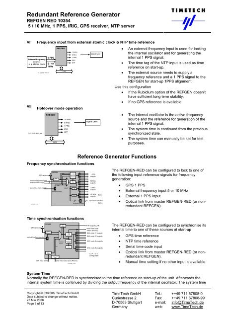
VI Frequency input from external atomic clock & NTP time reference<br />
External frequency<br />
source,<br />
e. g. atomic clock<br />
15.12.2005 - Ap9 mw<br />
1 PPS<br />
5 / 10<br />
MHz<br />
REFGEN<br />
LAN<br />
10 MHz<br />
5 MHz<br />
1 PPS<br />
IRIG<br />
NTP<br />
VII Holdover mode operation<br />
15.12.2005 - Ap10 mw<br />
REFGEN<br />
LAN<br />
10 MHz<br />
5 MHz<br />
1 PPS<br />
IRIG<br />
NTP<br />
Copyright © 03/2006, <strong>TimeTech</strong> <strong>GmbH</strong><br />
Data subject to change <strong>with</strong>out notice.<br />
25 Mar 2006<br />
Page 6 of 13<br />
signal user<br />
signal user<br />
Frequency synchronisation functions<br />
external frequency input<br />
external 1 PPS input<br />
04.01.2006 - A1 mw<br />
GPS antenna<br />
optical link from master<br />
1<br />
2<br />
REFGEN<br />
GPS<br />
Receiver<br />
2<br />
1 PPS<br />
slave function<br />
1 PPS<br />
clock input<br />
selector<br />
1 PPS<br />
generator<br />
/monitor<br />
PLL<br />
: 2<br />
X 20<br />
• An external frequency input is used for locking<br />
the internal oscillator and for generating the<br />
internal 1 PPS signal.<br />
• The time tag of the NTP input is used as time<br />
reference on start-up.<br />
• The external source needs to supply a<br />
frequency reference and a 1 PPS signal to the<br />
REFGEN for start-up 1PPS alignment.<br />
Use this configuration<br />
• If the Rubidium option of the REFGEN doesn’t<br />
have sufficient long term stability.<br />
• If no GPS reference is available.<br />
<strong>Reference</strong> <strong>Generator</strong> Functions<br />
4 4<br />
2<br />
master function<br />
Time synchronisation functions<br />
GPS antenna<br />
optical link from master<br />
REFGEN<br />
GPS<br />
Receiver<br />
2<br />
NTP<br />
client<br />
time<br />
serial time<br />
code<br />
NTP<br />
server<br />
time input<br />
selector<br />
Time<br />
code<br />
generator<br />
1 PPS<br />
generator<br />
/monitor<br />
NTP input (LAN) Serial time code input (RS232)<br />
PLL<br />
04.01.2006 - A2 mw<br />
1 PPS<br />
outputs<br />
10 MHz<br />
outputs<br />
5 MHz<br />
outputs<br />
100 MHz<br />
outputs<br />
Option<br />
optical link interface<br />
Option<br />
NTP output (LAN)<br />
serial time code<br />
output (RS232)<br />
IRIG code #1 outputs<br />
IRIG code #2 outputs<br />
IRIG code #x outputs<br />
IRIG code #y outputs<br />
x,y = 1 or 2<br />
configurable<br />
• The internal oscillator is the active frequency<br />
source and the reference for generation of the<br />
internal 1 PPS signal.<br />
• The system time is continued from the previous<br />
synchronized state.<br />
• The system time can manually be set for test<br />
purposes.<br />
The REFGEN-RED can be configured to lock to one of<br />
the following input reference signals for frequency<br />
generation:<br />
• GPS 1 PPS<br />
• External frequency input 5 or 10 MHz<br />
• External 1 PPS input<br />
• Optical link from master REFGEN-RED (or nonredundant<br />
REFGEN).<br />
The REFGEN-RED can be configured to synchronise its<br />
internal time to one of these sources at start-up<br />
• GPS time reference<br />
• NTP time reference<br />
• Serial time code input<br />
• Optical link from master REFGEN-RED (or nonredundant<br />
REFGEN).<br />
• Manual time setting if no other input is available.<br />
System Time<br />
Normally the REFGEN-RED is synchronised to the time reference on start-up of the unit. Afterwards the<br />
internal system time is continued by dividing the output frequency of the internal oscillator. The system time<br />
<strong>TimeTech</strong> <strong>GmbH</strong> Tel.: ++49 711 67808-0<br />
Curiestrasse 2 Fax: ++49 711 67808-99<br />
D-70563 Stuttgart e-mail: info@<strong>TimeTech</strong>.de<br />
Germany web: www.<strong>TimeTech</strong>.de


