H. G. Brokmeier, B. Weiss, S. B. Yi, W. Ye, K.-D. Liss, T. Lippmann
H. G. Brokmeier, B. Weiss, S. B. Yi, W. Ye, K.-D. Liss, T. Lippmann
H. G. Brokmeier, B. Weiss, S. B. Yi, W. Ye, K.-D. Liss, T. Lippmann

Create successful ePaper yourself
Turn your PDF publications into a flip-book with our unique Google optimized e-Paper software.
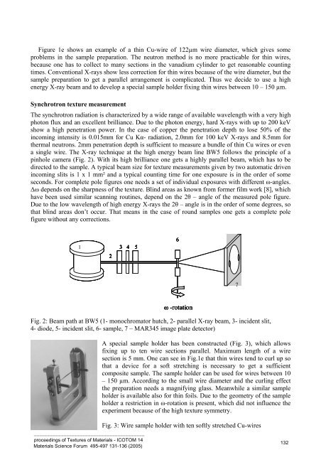
Figure 1e shows an example of a thin Cu-wire of 122µm wire diameter, which gives someproblems in the sample preparation. The neutron method is no more practicable for thin wires,because one has to collect to many sections in the vanadium cylinder to get reasonable countingtimes. Conventional X-rays show less correction for thin wires because of the wire diameter, but thesample preparation to get a parallel arrangement is complicated. Thus we decide to use a highenergy X-ray beam and to develop a special sample holder fixing thin wires between 10 – 150 µm.Synchrotron texture measurementThe synchrotron radiation is characterized by a wide range of available wavelength with a very highphoton flux and an excellent brilliance. Due to the photon energy, hard X-rays with up to 200 keVshow a high penetration power. In the case of copper the penetration depth to lose 50% of theincoming intensity is 0.015mm for Cu Kα- radiation, 2.0mm for 100 keV X-rays and 8.5mm forthermal neutrons. 2mm penetration depth is sufficient to measure a bundle of thin Cu wires or evena single wire. The X-ray technique at the high energy beam line BW5 follows the principle of apinhole camera (Fig. 2). With its high brilliance one gets a highly parallel beam, which has to bedirected to the sample. A typical beam size for texture measurements given by two automatic drivenincoming slits is 1 x 1 mm² and a typical counting time for one exposure is in the order of someseconds. For complete pole figures one needs a set of individual exposures with different ω-angles.∆ω depends on the sharpness of the texture. Blind areas as known from former film work [8], whichhave been used similar scanning routines, depend on the 2θ – angle of the measured pole figure.Due to the low wavelength of high energy X-rays the 2θ – angle is in the order of some degrees, sothat blind areas don’t occur. That means in the case of round samples one gets a complete polefigure without any corrections.134 5627ω -rotationFig. 2: Beam path at BW5 (1- monochromator hutch, 2- parallel X-ray beam, 3- incident slit,4- diode, 5- incident slit, 6- sample, 7 – MAR345 image plate detector)A special sample holder has been constructed (Fig. 3), which allowsfixing up to ten wire sections parallel. Maximum length of a wiresection is 5 mm. One can see in Fig.1e that thin wires tend to curl up sothat a device for a soft stretching is necessary to get a sufficientcomposite sample. The sample holder can be used for wires between 10– 150 µm. According to the small wire diameter and the curling effectthe preparation needs a magnifying glass. Meanwhile a similar sampleholder is available also for thin foils. Due to the geometry of the sampleholder a restriction in ω-rotation is present, which did not influence theexperiment because of the high texture symmetry._________________________________________proceedings of Textures of Materials - ICOTOM 14Materials Science Forum 495-497 131-136 (2005)Fig. 3: Wire sample holder with ten softly stretched Cu-wires1 32