VIESMANN - Viessmann
VIESMANN - Viessmann
VIESMANN - Viessmann

Create successful ePaper yourself
Turn your PDF publications into a flip-book with our unique Google optimized e-Paper software.
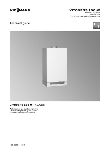
<strong>VIESMANN</strong> VITODENS 200-W<br />
Gas condensing boiler<br />
17.0 to 105.0 kW<br />
as a multi-boiler system up to 420.0 kW<br />
Technical guide<br />
VITODENS 200-W Type WB2B<br />
Wall mounted gas condensing boiler,<br />
with modulating MatriX cylinder burner<br />
for open or balanced flue operation<br />
5822 432 GB 6/2009
Index<br />
Index<br />
1. Vitodens 200-W 1.1 Product description ....................................................................................................... 4<br />
1.2 Specification ................................................................................................................. 6<br />
■ Vitodens 200-W, 45 and 60 kW ................................................................................ 7<br />
■ Vitodens 200-W, 80 and 105 kW .............................................................................. 11<br />
2. Installation accessories 2.1 Product description ....................................................................................................... 14<br />
■ Installation accessories for the Vitodens 200-W, 45 and 60 kW ............................... 14<br />
■ Installation accessories for the Vitodens 200-W, 80 and 105 kW ............................. 19<br />
■ Installation accessories for multi-boiler systems ....................................................... 20<br />
3. DHW cylinder 3.1 Product description ....................................................................................................... 21<br />
4. Design information 4.1 Positioning, installation ................................................................................................. 21<br />
■ Installation conditions for open flue operation (appliance type B) ............................. 21<br />
■ Installation conditions for balanced flue operation (appliance type C) ...................... 21<br />
■ Operation of the Vitodens in wet areas ..................................................................... 22<br />
■ Electrical connection ................................................................................................. 22<br />
■ Gas connection ......................................................................................................... 23<br />
■ Minimum clearances ................................................................................................. 23<br />
■ Pre-installation for installing the Vitodens 200-W directly onto a wall ....................... 24<br />
■ Pre-installation, multi-boiler system .......................................................................... 24<br />
4.2 Condensate connection ................................................................................................ 29<br />
■ Condensate drain and neutralisation ........................................................................ 29<br />
4.3 Hydraulic connection .................................................................................................... 31<br />
■ General ..................................................................................................................... 31<br />
■ Expansion vessels .................................................................................................... 31<br />
■ Low loss header ........................................................................................................ 31<br />
5. Control units 5.1 Vitotronic 100, type HC1, for constant temperature operation ...................................... 33<br />
■ Structure and functions ............................................................................................. 33<br />
■ Specification, Vitotronic 100 ...................................................................................... 33<br />
5.2 Vitotronic 200, type HO1, for weather-compensated operation .................................... 33<br />
■ Specification, Vitotronic 200 ...................................................................................... 35<br />
5.3 Vitotronic 300-K, type MW2 for multi-boiler systems .................................................... 35<br />
■ Cascade control unit for the Vitodens 200-W with a Vitotronic 100 .......................... 35<br />
■ Construction and function ......................................................................................... 35<br />
■ Specification, Vitotronic 300-K .................................................................................. 37<br />
■ Delivered condition Vitotronic 300-K ......................................................................... 38<br />
5.4 Accessories for the Vitotronic ....................................................................................... 38<br />
■ Allocation to control unit types .................................................................................. 38<br />
■ Vitotrol 100, type UTA ............................................................................................... 39<br />
■ Vitotrol 100, type UTD ............................................................................................... 39<br />
■ External extension H4 ............................................................................................... 40<br />
■ Vitotrol 100, type UTD-RF ......................................................................................... 40<br />
■ Notes regarding room temperature hook-up (RS function) for remote control units . 40<br />
■ Information regarding the Vitotrol 200 and 300 ......................................................... 41<br />
■ Vitotrol 200 ................................................................................................................ 41<br />
■ Vitotrol 300 ................................................................................................................ 41<br />
■ Room temperature sensor ........................................................................................ 42<br />
■ Radio clock receiver .................................................................................................. 42<br />
■ Function extension 0 to 10 V .................................................................................... 42<br />
■ Vitocom 100, type GSM ............................................................................................ 43<br />
■ Extension kit for one heating circuit with mixer with integral mixer motor ................. 43<br />
■ Extension kit for one heating circuit with mixer for separate mixer motor ................. 44<br />
■ Extension kit for one heating circuit with mixer for the Vitotronic 300-K ................... 44<br />
■ Immersion thermostat ............................................................................................... 45<br />
■ Contact thermostat .................................................................................................... 45<br />
■ Immersion temperature sensor ................................................................................. 46<br />
■ LON communication module ..................................................................................... 46<br />
■ LON connecting cable for data exchange between control units .............................. 46<br />
■ Extension of the connecting cable ............................................................................ 47<br />
■ Terminator (2 pce.) ................................................................................................... 47<br />
■ KM BUS distributor ................................................................................................... 47<br />
■ Internal extension H1 ................................................................................................ 47<br />
■ Internal extension H2 ................................................................................................ 47<br />
■ External extension H1 ............................................................................................... 48<br />
■ External extension H2 ............................................................................................... 48<br />
2 <strong>VIESMANN</strong> VITODENS 200-W<br />
5822 432 GB
5822 432 GB<br />
Index (cont.)<br />
6. Appendix 6.1 Regulations / Directives ................................................................................................ 49<br />
■ Regulations and Directives ....................................................................................... 49<br />
7. Keyword index .............................................................................................................................................. 50<br />
VITODENS 200-W <strong>VIESMANN</strong> 3
1<br />
Vitodens 200-W<br />
1.1 Product description<br />
Vitodens 200-W wall mounted condensing boilers up to 105 kW are<br />
especially suitable for installation in apartment buildings and commercial<br />
or public buildings. For these, the Vitodens 200-W offers an affordable,<br />
space-saving solution – either as a single unit up to 105 kW or<br />
as a cascade with up to four boilers and an output up to 420 kW.<br />
The Inox-Radial heat exchanger made from stainless steel offers high<br />
output in the tightest of spaces. This enables particularly efficient operation<br />
with standard efficiency up to 98 % (H s)/109 % (H i).<br />
The Vitotronic 300-K cascade control unit regulates up to four Vitodens<br />
200-W as a single heating centre. In this way, the boiler output is automatically<br />
matched to the heat demand. This means subject to the prevailing<br />
demand, either one boiler modulates or all four boilers operate<br />
concurrently.<br />
For the construction of cascade systems, we offer perfectly matching<br />
system design, e.g. control units with up to four appliances, fully insulated<br />
hydraulic cascades or flue gas headers.<br />
Recommended applications<br />
High output from a compact, user-friendly wall mounted boiler, suitable<br />
for the following applications:<br />
■ Systems with few, large-demand consumers, e.g. fan heaters in<br />
supermarkets/markets, workshops and industrial premises, nurseries,<br />
garages and DHW heating systems<br />
■ Systems with several heating circuits for underfloor and/or static<br />
radiators in multi-occupancy dwellings, central heating plants for terraced<br />
houses, office buildings and administration premises - particularly<br />
suitable for attic heating centres<br />
■ Heating of public buildings, such as sports and multi-purpose halls,<br />
schools, kindergartens<br />
■ Suitable for installation in basement boiler rooms, on single floors or<br />
in the attic.<br />
A Inox-Radial heat exchanger made from stainless steel - for high<br />
operational reliability and a long service life. Large output in the<br />
smallest of spaces<br />
B Modulating MatriX cylinder burner for extremely clean combustion<br />
and quiet operation<br />
C Variable speed combustion fan for quiet and economical operation<br />
D Gas and water connections<br />
E Digital boiler control unit<br />
Benefits at a glance<br />
■ Wall mounted gas condensing boiler as central heating boiler, 17 to<br />
105 kW<br />
■ As multi-boiler system with cascade control and up to 4 Vitodens<br />
200-W (up to 420 kW)<br />
■ Seasonal efficiency [to DIN]: up to 98 % (H s)/109 % (H i)<br />
■ Stainless steel Inox-Radial heat exchanger<br />
– Self-cleaning of the smooth stainless steel surfaces through the<br />
flue gas and the condensate flowing in the same direction<br />
– Excellent corrosion resistance through high-grade stainless steel<br />
1.4571<br />
■ Modulating MatriX cylinder burner – in-house development and<br />
manufacture<br />
– Low emissions<br />
– Long service life through stainless steel MatriX mesh<br />
– Optimised match between the heat exchanger and the burner<br />
■ Intelligent Lambda Pro Control combustion controller<br />
– A change in the gas type requires no change of nozzle<br />
– Consistently high efficiency, even in case of fluctuating gas composition<br />
– Consistently low emissions<br />
– Low combustion noise through low fan speed<br />
Delivered condition<br />
Wall mounted gas condensing boiler with Inox-Radial heat exchanger,<br />
modulating MatriX cylinder burner for natural gas and LPG (45 and<br />
60 kW) or natural gas (80 and 105 kW) to DVGW Code of Practice<br />
G260 [Germany], and wall retainer.<br />
Fully plumbed and wired. Colour of the epoxy-coated casing: white.<br />
Packed separately:<br />
Vitotronic 100 for constant temperature mode<br />
or<br />
Vitotronic 200 for weather-compensated operation.<br />
4 <strong>VIESMANN</strong> VITODENS 200-W<br />
5822 432 GB
5822 432 GB<br />
Vitodens 200-W (cont.)<br />
Set up for operation with natural gas. A conversion within the gas group<br />
E/LL is not required. The conversion to LPG (up to 60 kW only) is made<br />
at the gas valve (conversion kit not required).<br />
Multi-boiler systems<br />
Multi-boiler systems for open flue operation with 2, 3 or 4 boilers.<br />
Installation on a wall in series<br />
Comprising:<br />
■ Hydraulic cascade with low loss header and thermal insulation<br />
■ Connection set for every boiler with:<br />
– Interconnecting pipes formed to suit<br />
– Circulation pump (3-stage)<br />
– Ball valves<br />
– Fill & drain valve<br />
– Check valve<br />
– Gas shut-off valve<br />
– Safety valve<br />
■ Thermal insulation<br />
■ Sensor well for flow temperature sensor<br />
■ Weather-compensated, digital cascade and heating circuit control<br />
unit Vitotronic 300-K<br />
■ Cascade communication module for each boiler<br />
Installation with a self-supporting mounting frame in series and<br />
as a single block<br />
Comprising:<br />
■ Hydraulic cascade with low loss header and thermal insulation<br />
■ Connection set for every boiler with:<br />
– Interconnecting pipes formed to suit<br />
– Circulation pump (3-stage)<br />
– Ball valves<br />
– Fill & drain valve<br />
– Check valve<br />
– Gas shut-off valve<br />
– Safety valve<br />
■ Thermal insulation<br />
■ Sensor well for flow temperature sensor<br />
■ Weather-compensated, digital cascade and heating circuit control<br />
unit Vitotronic 300-K<br />
■ Cascade communication module for each boiler<br />
■ Mounting frame<br />
– Ceiling mounting<br />
Note<br />
Order circulation pumps for heating circuits and cylinder heating separately.<br />
Approved quality<br />
VDE designation approval applied for<br />
CE designation according to current EC Directives<br />
Meets the requirements for the "Blue Angel" certificate of environmental<br />
excellence to RAL UZ 61.<br />
VITODENS 200-W <strong>VIESMANN</strong> 5<br />
1
1<br />
Vitodens 200-W (cont.)<br />
1.2 Specification<br />
Gas boiler, series B and C, category II 2N3P II 2N3P I 2N I 2N<br />
Gas condensing boiler<br />
Rated output range<br />
45 and 60 kW: Specification to EN 677.<br />
80 and 105 kW: Specification to EN 15417.<br />
T V/T R = 50/30 °C kW 17.0-45.0 17.0-60.0 30.0-80.0 30.0-105.0<br />
T V/T R = 80/60 °C kW 15.4-40.7 15.4-54.4 27.0-72.6 27.0-95.6<br />
Rated thermal load kW 16.1-42.2 16.1-56.2 28.1-75.0 28.1-98.5<br />
Type WB2B WB2B WB2B WB2B<br />
Product ID CE-0085 BR 0432<br />
IP rating<br />
Gas supply pressure<br />
IP X4D to EN 60529<br />
Natural gas mbar 20 20 20 20<br />
LPG<br />
Max. permissible gas supply pressure<br />
mbar 50 50 — —<br />
*1<br />
Natural gas mbar 25.0 25.0 25.0 25.0<br />
LPG mbar 57.5 57.5 — —<br />
Max. power consumption W 30 50 105 150<br />
Weight kg 65 65 83 83<br />
Heat exchanger capacity l 7.0 7.0 12.8 12.8<br />
Max. flow rate<br />
Limit for the use of hydraulic separation<br />
l/h 3500 3500 5700 5700<br />
Rated circulation water volume at TV/TR = 80/60 °C l/h 1748 2336 3118 4106<br />
Permiss. operating pressure bar 4 4 4 4<br />
Dimensions<br />
Length mm 380 380 530 530<br />
Width mm 480 480 480 480<br />
Height mm 850 850 850 850<br />
Gas connection R ¾" ¾" 1" 1"<br />
Connection values<br />
in relation to the max. load<br />
with gas<br />
Natural gas E m 3 /h 4.47 5.95 7.94 10.42<br />
Natural gas LL m 3 /h 5.19 6.91 9.23 12.12<br />
LPG kg/h 3.30 4.39 — —<br />
Flue gas parameters *2<br />
Flue gas value group to G 635/G 636 G 52/G 51 G 52/G 51 G 52/G 51 G 52/G 51<br />
Temperature (at 30 °C return temperature)<br />
– at rated output °C 35 40 35 40<br />
– at partial load °C 33 35 33 35<br />
Temperature (at return temperature 60 °C) °C 65 70 65 70<br />
Mass flow rate<br />
Natural gas<br />
– at rated output kg/h 81.2 110.6 147.5 193.3<br />
– at partial load kg/h 31.1 31.1 55.8 55.8<br />
LPG<br />
– at rated output kg/h 78.2 106.7 — —<br />
– at partial load kg/h 26.6 26.6 — —<br />
Available draught Pa 250 250 250 250<br />
mbar 2.5 2.5 2.5 2.5<br />
Standard efficiency at<br />
T V/T R = 40/30 °C % up to 98 (H s)/109 (H i)<br />
Average condensate volume<br />
with natural gas and T V/T R = 50/30 °C l/day 14-19 23-28 25-30 35-40<br />
Internal pipe diameter to<br />
expansion vessel DN 22 22 28 28<br />
safety valve DN 22 22 22 22<br />
Condensate connection (hose nozzle) Ø mm 20-24 20-24 20-24 20-24<br />
*1 If the gas supply pressure is higher than the maximum permitted value, install a separate gas pressure governor upstream of the system.<br />
*2 Calculation values for sizing the flue gas system to EN 13384.<br />
Flue gas temperatures measured as gross values at 20 °C combustion air temperature.<br />
The flue gas temperature at a return temperature of 30 °C is significant for the sizing of the flue system.<br />
The flue gas temperature at a return temperature of 60 °C is used to determine the application range of flue pipes with maximum permissible<br />
operating temperatures.<br />
6 <strong>VIESMANN</strong> VITODENS 200-W<br />
5822 432 GB
5822 432 GB<br />
Vitodens 200-W (cont.)<br />
Gas boiler, series B and C, category II 2N3P II 2N3P I 2N I 2N<br />
Gas condensing boiler<br />
Rated output range<br />
45 and 60 kW: Specification to EN 677.<br />
80 and 105 kW: Specification to EN 15417.<br />
T V/T R = 50/30 °C kW 17.0-45.0 17.0-60.0 30.0-80.0 30.0-105.0<br />
T V/T R = 80/60 °C kW 15.4-40.7 15.4-54.4 27.0-72.6 27.0-95.6<br />
Flue gas connection Ø mm 80 80 100 100<br />
Ventilation air connection Ø mm 125 125 150 150<br />
Vitodens 200-W, 45 and 60 kW<br />
Multi-boiler systems<br />
For further details regarding multi-boiler systems, see page 24.<br />
A<br />
H<br />
E<br />
480<br />
200<br />
B C D F<br />
400<br />
G176<br />
240<br />
305<br />
80<br />
752<br />
40<br />
A Expansion vessel connection G 1"<br />
B Safety valve<br />
C Heating flow G 1½"<br />
D Cylinder flow G 1½"<br />
E Gas connection R ¾"<br />
F Cylinder return G 1½"<br />
G Heating return G 1½"<br />
P<br />
L<br />
875<br />
K<br />
M<br />
1166<br />
N<br />
O<br />
1975<br />
1700<br />
R<br />
160<br />
100<br />
380<br />
S<br />
B<br />
850<br />
902<br />
982<br />
H Cable entry area at the back<br />
K Connection sets (accessory)<br />
Shown without thermal insulation (standard delivery, connection<br />
sets)<br />
L Without connection sets<br />
M With connection sets<br />
N Recommended dimension for a single boiler system<br />
VITODENS 200-W <strong>VIESMANN</strong> 7<br />
1
1<br />
Vitodens 200-W (cont.)<br />
O Recommended dimension for a multi-boiler system<br />
P Flue gas/ventilation air connection with bend (accessory)<br />
Note<br />
Route all required supply cables on site and lead them into the boiler<br />
at the point indicated (see page 22).<br />
R Condensate drain<br />
S Top edge finished floor<br />
Variable speed heating circuit pump in the heating circuit connection set (accessory)<br />
The pump speed and consequently the pump rate is relayed to the<br />
pump and adjusted by the control unit subject to outside temperature<br />
and switching times for central heating or reduced mode via a data<br />
BUS.<br />
Individually match the minimum and maximum speed plus the speed<br />
for reduced mode to the existing heating system using the control unit<br />
codes.<br />
Using the diagram, the pump rate can be adjusted to the respective<br />
system conditions.<br />
Matching the pump rate of the circulation pump to the individual system<br />
conditions reduces the power consumption of the heating system.<br />
Circulation pump VIRS 7 BUS<br />
Rated voltage V~ 230<br />
Rated current A max. 0.55<br />
min. 0.37<br />
Condenser µF 3.5<br />
Power consumption W max. 126<br />
min. 42<br />
in the delivered condition 93<br />
Variable speed, fully wired, ready to plug in.<br />
8 <strong>VIESMANN</strong> VITODENS 200-W<br />
5822 432 GB
5822 432 GB<br />
Residual head of the circulation pump<br />
kPa<br />
Vitodens 200-W (cont.)<br />
70<br />
60<br />
50<br />
40<br />
30<br />
20<br />
10<br />
0<br />
Residual head in mbar<br />
700<br />
600<br />
500<br />
400<br />
300<br />
200<br />
100<br />
0 0 200 400 600 800 1000<br />
Flow rate in l/h<br />
Curve Circulation pump rate Setting code address "E6"<br />
A 30 % E6:030<br />
B 40 % E6:040<br />
C 50 % E6:050<br />
D 60 % E6:060<br />
E 70 % E6:070<br />
F 80 % E6:080<br />
G 90 % E6:090<br />
H 100 % E6:100<br />
A B C D E F G H<br />
1200 1400 1600 1800 2000 2200 2400 2600<br />
3-speed heating circuit pump in the heating circuit connection set (accessory)<br />
Circulation pump VIRS 25/7-3<br />
Rated voltage V~ 230<br />
Rated current A max. 0.58<br />
min. 0.30<br />
Condenser µF 3.5<br />
Power consumption W Stage 1 62<br />
Stage 2 92<br />
Stage 3 132<br />
3-stage, fully wired ready, to plug in.<br />
VITODENS 200-W <strong>VIESMANN</strong> 9<br />
1
1<br />
Residual head of the circulation pump<br />
kPa<br />
Vitodens 200-W (cont.)<br />
70<br />
60<br />
50<br />
40<br />
30<br />
20<br />
10<br />
0<br />
Residual head in mbar<br />
700<br />
600<br />
500<br />
400<br />
300<br />
200<br />
100<br />
A Stage 1<br />
B Stage 2<br />
C Stage 3<br />
A B C<br />
0 0 200 400 600 800 1000<br />
Flow rate in l/h<br />
Pressure drop (on the heating water side)<br />
For sizing an on-site circulation pump<br />
kPa<br />
60<br />
50<br />
40<br />
30<br />
20<br />
10<br />
0<br />
Pressure drop in mbar<br />
600<br />
500<br />
400<br />
300<br />
200<br />
100<br />
0<br />
0 500 1000 1500<br />
Flow rate in l/h<br />
Circulation pump in the connection set for DHW cylinders<br />
Pump type VI RS 25/6-3<br />
Voltage V~ 230<br />
Power consumption W max. 93<br />
min. 46<br />
1200 1400 1600 1800 2000 2200 2400 2600<br />
2000 2500 3000 3500<br />
10 <strong>VIESMANN</strong> VITODENS 200-W<br />
5822 432 GB
5822 432 GB<br />
Vitodens 200-W (cont.)<br />
Residual head of the circulation pump<br />
kPa<br />
60<br />
50<br />
40<br />
30<br />
20<br />
10<br />
0<br />
Head in mbar<br />
A Stage 1<br />
B Stage 2<br />
C Stage 3<br />
600<br />
500<br />
400<br />
300<br />
200<br />
100<br />
A B C<br />
0<br />
0 0,5 1 1,5<br />
Pump rate in m³/h<br />
Vitodens 200-W, 80 and 105 kW<br />
Multi-boiler systems<br />
For further details regarding multi-boiler systems, see page 24.<br />
A<br />
B<br />
K<br />
E<br />
480<br />
200<br />
D F<br />
160 160<br />
C G<br />
752<br />
40<br />
L<br />
875<br />
H<br />
A Safety valve<br />
B Expansion vessel connection G 1"<br />
C Boiler flow 7 42 mm<br />
D Cylinder flow 7 35 mm<br />
E Gas connection R 1"<br />
M<br />
1300<br />
N<br />
O<br />
1975<br />
2 2,5 3 3,5<br />
1700<br />
P<br />
100<br />
236<br />
530<br />
850<br />
F Cylinder return 7 35 mm<br />
G Boiler return 7 42 mm<br />
H Connection sets (accessory)<br />
Shown without thermal insulation (standard delivery, connection<br />
sets)<br />
VITODENS 200-W <strong>VIESMANN</strong> 11<br />
1
1<br />
Vitodens 200-W (cont.)<br />
K Cable entry area at the back<br />
L Without connection set (accessories)<br />
M With connection set (accessories)<br />
Note<br />
The heating circuit connection set must be ordered separately.<br />
3-speed heating circuit pump in the heating circuit connection set (accessory)<br />
Circulation pump VI TOP-S25/10-3<br />
Rated voltage V~ 230<br />
Rated current A max. 2.08<br />
min. 1.75<br />
Power consumption W Stage 1 340<br />
Stage 2 395<br />
Stage 3 410<br />
3-stage, fully wired ready, to plug in.<br />
Residual head of the circulation pump<br />
kPa<br />
120<br />
110<br />
100<br />
90<br />
80<br />
70<br />
60<br />
50<br />
40<br />
30<br />
20<br />
10<br />
0<br />
Residual head in mbar<br />
A Stage 1<br />
B Stage 2<br />
C Stage 3<br />
1200<br />
1100<br />
1000<br />
900<br />
800<br />
700<br />
600<br />
500<br />
400<br />
300<br />
200<br />
100<br />
0 0 1000<br />
Flow rate in l/h<br />
Note<br />
Observe further details regarding the use of a low loss header (see<br />
page 31).<br />
If the residual head of the circulation pump available as an accessory<br />
is insufficient to overcome the following system pressure drop values,<br />
install an additional, external circulation pump on site.<br />
In such cases, use a low loss header.<br />
Pressure drop (on the heating water side)<br />
For sizing a circulation pump on site (when connecting to DHW cylinder<br />
from connection set)<br />
N Recommended dimension (single boiler system)<br />
O Recommended dimension (multi-boiler system)<br />
P Condensate drain<br />
Note<br />
Route all required supply cables on site and lead them into the boiler<br />
at the point indicated (see page 22).<br />
2000 3000 4000 5000<br />
12 <strong>VIESMANN</strong> VITODENS 200-W<br />
A<br />
B<br />
C<br />
5822 432 GB
5822 432 GB<br />
Vitodens 200-W (cont.)<br />
kPa<br />
60<br />
50<br />
40<br />
30<br />
20<br />
10<br />
0<br />
Pressure drop in mbar<br />
600<br />
500<br />
400<br />
300<br />
200<br />
100<br />
0<br />
0 1000 2000 3000<br />
Flow rate in l/h<br />
4000 5000 6000 7000<br />
VITODENS 200-W <strong>VIESMANN</strong> 13<br />
1
2<br />
Installation accessories<br />
2.1 Product description<br />
Installation accessories for the Vitodens 200-W, 45 and 60 kW<br />
Heating circuit connection set without circulation pump<br />
Part no. 7245 738<br />
Connections G 1½"<br />
Comprising:<br />
■ Tee with ball valve<br />
■ BDF valve<br />
■ Safety valve<br />
■ Gas shut-off valve with integral thermal safety shut-off valve<br />
■ Connection G 1" for expansion vessel<br />
Heating circuit connection set with variable speed circulation<br />
pump<br />
Part no. 7247 374<br />
Connections G 1½"<br />
Comprising:<br />
■ Circulation pump, variable speed, Wilo type VIRS-25/7 BUS<br />
■ 2 tees with ball valve<br />
■ Check valve<br />
■ 2 BDF valves<br />
■ Safety valve<br />
■ Gas shut-off valve with integral thermal safety shut-off valve<br />
■ Thermal insulation<br />
■ Connection G 1" for expansion vessel<br />
Heating circuit connection set with 3-stage circulation pump<br />
Part no. 7247 341<br />
Connections G 1½"<br />
Modular Divicon heating circuit distributor<br />
Comprising:<br />
■ Circulation pump, 3-stage, Wilo type VIRS-25/7-3<br />
■ 2 tees with ball valve<br />
■ Check valve<br />
■ 2 BDF valves<br />
■ Safety valve<br />
■ Gas shut-off valve with integral thermal safety shut-off valve<br />
■ Thermal insulation<br />
■ Connection G 1" for expansion vessel<br />
Connection set for DHW cylinders<br />
Part no. Z006 183<br />
Connections G 1½"<br />
Comprising:<br />
■ Circulation pump, Wilo type VIRS-25/6-3<br />
■ 2 ball shut-off valves<br />
■ Check valve<br />
■ Cylinder temperature sensor<br />
Ball valve<br />
Part no. 7247 373<br />
1 pce. G 1¼" with gasket and union nut.<br />
For part no. in conjunction with the different circulation pumps, see <strong>Viessmann</strong> pricelist.<br />
14 <strong>VIESMANN</strong> VITODENS 200-W<br />
5822 432 GB
5822 432 GB<br />
A<br />
B<br />
C<br />
D<br />
E<br />
501<br />
120<br />
HV HR<br />
HV 120 HR<br />
Diagram without thermal insulation, wall mounted<br />
HR Heating return<br />
HV Heating flow<br />
A Ball valves with thermometer (as programming unit)<br />
Determining the required internal diameter<br />
Throughput in m³/h<br />
Installation accessories (cont.)<br />
5,0<br />
2,0<br />
1,5<br />
1,0<br />
0,5<br />
0,2<br />
0,1<br />
1<br />
2<br />
3 4 5 6<br />
Pressure drop in mbar<br />
8 10<br />
A<br />
B<br />
C<br />
89<br />
20 30 50 80<br />
40 60 100<br />
200<br />
A Modular-Divicon with mixer-3<br />
The identified operating ranges F and G provide optimum control<br />
characteristics with the Modular-Divicon mixer:<br />
B Modular-Divicon with mixer-3 (R ¾")<br />
Application range: 0 to 1.0 m 3 /h<br />
C Modular-Divicon with mixer-3 (R 1")<br />
Application range: 0 to 1.5 m 3 /h<br />
B Connection for overflow valve<br />
C Circulation pump<br />
D Connection for bypass valve (only for versions with mixer)<br />
E Mixer-3<br />
Heating circuit distributor with or without mixer. Incl. thermal insulation.<br />
The dimensions of the heating circuit distributor are the same, with or<br />
without mixer.<br />
Heating circuit connection R ¾ 1<br />
Flow rate (max.) m 3 /h 1.0 1.5<br />
Installation example: Modular-Divicon with triple distribution<br />
manifold<br />
HV<br />
120 120<br />
HR<br />
697<br />
HR Heating return<br />
HV Heating flow<br />
1<br />
3<br />
5<br />
Heating circuit output<br />
in kW<br />
120<br />
G1"¼"<br />
ΔT= 5K<br />
132<br />
635<br />
ΔT= 10K<br />
ΔT= 15K<br />
ΔT= 20K<br />
ΔT= 30K<br />
5,0<br />
2,0<br />
1,5<br />
1,0<br />
0,5<br />
0,2<br />
0,1<br />
10 20 30 40<br />
VITODENS 200-W <strong>VIESMANN</strong> 15<br />
2
2<br />
Installation accessories (cont.)<br />
Example:<br />
Heating circuit for radiators with an output of Q = 11.6 kW<br />
Heating system temperature 75/60 °C (ΔT = 15 K)<br />
Flow rate ´<br />
² = µ · c · ΔT c = 1.163 Wh<br />
kg · K<br />
´ =<br />
²<br />
c · ΔT =<br />
11600 W · kg · K<br />
1.163 Wh · (75-60) K<br />
µ<br />
= 665<br />
kg<br />
h<br />
´ (1 kg ≈ 1 dm³)<br />
m³<br />
0.665<br />
h<br />
Select the smallest possible mixer within the application range with<br />
value ´.<br />
Bypass valve<br />
Part no. 9557 011<br />
To hydraulically balance the heating circuit. Is inserted into the Modular-Divicon.<br />
Overflow valve<br />
Part no. 9557 010<br />
Only with manually controlled heating circuit pump. Is inserted into the<br />
Modular-Divicon.<br />
Result of this example: Modular-Divicon with mixer-3 (R ¾")<br />
Manifold<br />
With thermal insulation<br />
The connection between boiler and manifold must be made on site.<br />
■ For 2 Modular-Divicon<br />
Part no. 7147 860<br />
130<br />
G 1½"<br />
HV 120 HR HV 120 HR<br />
120<br />
457<br />
Rp ¾"<br />
A HV HR<br />
C B<br />
A Heating flow drain<br />
B Heating return drain<br />
C Connection option for expansion vessel<br />
HV Heating water flow<br />
HR Heating water return<br />
■ For 3 Modular-Divicon<br />
Part no. 7147 861<br />
130<br />
697<br />
HV HR HV HR HV HR<br />
120<br />
120 120<br />
G 1 Rp<br />
120<br />
HV HR<br />
A Heating flow drain<br />
B Heating return drain<br />
C Connection option for expansion vessel<br />
HV Heating water flow<br />
HR Heating water return<br />
16 <strong>VIESMANN</strong> VITODENS 200-W<br />
5822 432 GB
5822 432 GB<br />
Installation accessories (cont.)<br />
Pressure drop<br />
Pressure<br />
drop<br />
kPa<br />
3<br />
2.5<br />
2<br />
1.5<br />
1<br />
0.5<br />
B<br />
A<br />
0<br />
0 0.5 1 1.5 2<br />
Flow rate in m³/h<br />
A opposite connection<br />
B remote connection<br />
Wall mounting – manifold<br />
Part no. 7147 887<br />
101-123<br />
Modular-Divicon wall mounting<br />
Part no. 7147 886<br />
Comprising screws, rawl plugs and spacers.<br />
Circulation pump curves and pressure drop on the heating water side<br />
The residual pump head results from the difference between the selected<br />
pump curve and the pressure drop curve of the respective heating<br />
circuit distributor or further components (pipe assembly, distributor<br />
etc.).<br />
The pressure drop curve of a Modular-Divicon is shown in the pump<br />
diagrams.<br />
The pressure drop curve is almost equal for all Modular-Divicon<br />
units.<br />
Maximum flow rate for Modular-Divicon:<br />
■ with R ¾" = 1.0 m 3 /h<br />
■ with R 1" = 1.5 m 3 /h<br />
Example:<br />
Flow rate V = 0,665 m 3 /h<br />
Low loss header<br />
Part no. 7148 100<br />
Flow rate max. 4.5 m 3 /h<br />
With thermal insulation and integral sensor well (50 mm long)<br />
The connection between boiler and low loss header must be made on<br />
site.<br />
275<br />
G 1<br />
HV 120 HR<br />
A Sensor well<br />
B Optional blow-down<br />
HV Heating water flow<br />
HR Heating water return<br />
Pressure drop<br />
Pressure<br />
drop<br />
kPa<br />
12<br />
10<br />
8<br />
6<br />
4<br />
2<br />
450<br />
HV HR<br />
360<br />
0 0 1 2 3 4 5<br />
Flow rate in m³/h<br />
Selected:<br />
Modular-Divicon with mixer R ¾" and circulation pump Wilo 4-3 Ku,<br />
pump curve 2, pump rate 0.7 m 3 /h<br />
Head of the relevant pump<br />
curve: 28 kPa<br />
Pressure drop – Modular-Divicon:<br />
2 kPa<br />
Residual head: 28 kPa –2 kPa = 26 kPa.<br />
Note<br />
For further components (pipe assembly, distributor, etc.) determine the<br />
pressure drop and deduct it from the residual head.<br />
VITODENS 200-W <strong>VIESMANN</strong> 17<br />
2
2<br />
Installation accessories (cont.)<br />
Manually controlled heating circuit pumps<br />
Wilo 4-3 Ku<br />
Pressure drop/head<br />
mWS<br />
5<br />
4<br />
3<br />
2<br />
1<br />
0<br />
40<br />
30<br />
20<br />
10<br />
Min.1<br />
Max. head 3<br />
0<br />
0 0.5 1.0 1.5 2.0 2.5<br />
Pump rate in m³/h<br />
kPa 50<br />
A Modular-Divicon<br />
Wilo 6-3 Ku<br />
Pressure drop/head<br />
mWS<br />
6<br />
5<br />
4<br />
3<br />
2<br />
1<br />
0<br />
60<br />
40<br />
30<br />
20<br />
10<br />
Max. head 3<br />
Min. head 1<br />
2<br />
0<br />
0 0.5 1.0 1.5 2.0 2.5<br />
Pump rate in m³/h<br />
kPa 50<br />
A Modular-Divicon<br />
2<br />
Heating circuit pumps regulated by differential pressure<br />
According to the [German] Energy Savings Order (EnEV), circulation<br />
pumps in central heating systems must be sized in accordance with<br />
current technical rules. Circulation pumps in central heating systems<br />
with rated output higher than 25 kW should be equipped and designed<br />
in such a way that the power consumption will be automatically<br />
matched to the operational (capacity) requirements in at least 3 stages,<br />
if no safety concerns relating to the boiler make demands to the contrary.<br />
A<br />
A<br />
Grundfos UPS-40<br />
Pressure drop/head<br />
mWS<br />
4<br />
3<br />
2<br />
1<br />
0<br />
kPa<br />
40<br />
30<br />
20<br />
10<br />
0<br />
A Modular-Divicon<br />
Grundfos UPS-60<br />
Pressure drop/head<br />
mWS<br />
6<br />
5<br />
4<br />
3<br />
2<br />
1<br />
0<br />
60<br />
40<br />
30<br />
20<br />
10<br />
Min. head<br />
Max. head<br />
A<br />
0 0.5 1.0 1.5 2.0 2.5<br />
Pump rate in m³/h<br />
Min. head<br />
Max. head<br />
A<br />
0<br />
0 0.5 1.0 1.5 2.0 2.5<br />
Pump rate in m³/h<br />
kPa 50<br />
A Modular-Divicon<br />
In addition to the EnEV regulations, the use of regulated pumps is also<br />
recommended for smaller capacities.<br />
Design information<br />
The use of differential pressure regulated heating circuit pumps<br />
requires heating circuits with variable flow rate, e.g. single line and<br />
twin-line systems with thermostatic valves, underfloor heating with<br />
thermostatic or zone valves.<br />
18 <strong>VIESMANN</strong> VITODENS 200-W<br />
5822 432 GB
5822 432 GB<br />
Installation accessories (cont.)<br />
Grundfos Alpha 2L<br />
Grundfos Alpha 2L is the simpler version of the standard pump Grundfos<br />
Alpha 2.<br />
■ Very economical HE DC pump (in accordance with Energy Label A)<br />
■ without power consumption indication<br />
■ without Autoadapt function (automatic matching to the pipework)<br />
■ without night setback function<br />
Grundfos Alpha 2<br />
■ Very economical HE DC pump (in accordance with Energy Label A)<br />
■ with power consumption indication<br />
■ with Autoadapt function (automatic matching to the pipework)<br />
■ with night setback function<br />
Grundfos Alpha 2L-40/Alpha 2-40<br />
Pressure drop/head<br />
mWS<br />
6<br />
5<br />
4<br />
3<br />
2<br />
1<br />
0<br />
60<br />
40<br />
30<br />
20<br />
10<br />
0<br />
0 0.5 1.0 1.5 2.0 2.5<br />
Pump rate in m³/h<br />
kPa 50<br />
A Modular-Divicon<br />
B Stage 1<br />
C Stage 2<br />
D Stage 3<br />
E Min. proportional pressure<br />
F Max. proportional pressure<br />
G Min. constant pressure<br />
H Max. constant pressure<br />
Grundfos Alpha 2L-60/Alpha 2-60<br />
Pressure drop/head<br />
mWS<br />
Installation accessories for the Vitodens 200-W, 80 and 105 kW<br />
Heating circuit connection set with 3-stage circulation pump<br />
Part no. 7345 107<br />
Comprising:<br />
■ Circulation pump, 3-stage, Wilo type VIRS-25/10-3<br />
■ 2 ball valves with adaptors Ø 42 mm (locking ring fitting)<br />
■ Tee with ball valve<br />
■ Check valve<br />
■ BDF valve<br />
■ Safety valve<br />
■ Gas shut-off valve with integral thermal safety shut-off valve<br />
■ Thermal insulation<br />
■ Connection G 1" for expansion vessel<br />
6<br />
5<br />
4<br />
3<br />
2<br />
1<br />
0<br />
60<br />
40<br />
30<br />
20<br />
10<br />
0<br />
0 0.5 1.0 1.5 2.0 2.5<br />
Pump rate in m³/h<br />
kPa 50<br />
A Modular-Divicon<br />
B Stage 1<br />
C Stage 2<br />
D Stage 3<br />
E Min. proportional pressure<br />
F Max. proportional pressure<br />
G Min. constant pressure<br />
H Max. constant pressure<br />
Low loss header<br />
For flow rate up to 8 m 3 /h<br />
Part no. Z007 743<br />
Comprising:<br />
■ Low loss header with integral sensor well (50 mm long)<br />
■ Thermal insulation<br />
■ Immersion temperature sensor for the low loss header<br />
VITODENS 200-W <strong>VIESMANN</strong> 19<br />
2
2<br />
Installation accessories (cont.)<br />
■ Quick-acting air vent valve<br />
■ 2 adaptors Ø 42 mm (locking ring fitting)<br />
963<br />
413<br />
204<br />
364<br />
160<br />
313<br />
Bracket for low loss header<br />
■ For floorstanding installation<br />
Part no. 7346 787<br />
■ For wall mounting<br />
Part no. 7346 788<br />
1078<br />
863<br />
Installation accessories for multi-boiler systems<br />
Hydraulic cascades<br />
See page 24.<br />
Flue gas cascade (positive pressure)<br />
Comprising:<br />
■ Flue gas non-return device for each boiler<br />
■ Flue gas header<br />
■ Terminal with condensate drain and siphon<br />
■ Boiler coding card<br />
C<br />
B<br />
B<br />
A Flue gas header<br />
B Flue gas non-return device<br />
C Terminal with siphon<br />
A<br />
B B<br />
Connection set for DHW cylinders<br />
Part no. 7348 934<br />
Connections: Ø 35 mm (locking ring fitting)<br />
Comprising:<br />
■ Connecting lines for flow and return<br />
■ Cylinder temperature sensor<br />
■ 2-boiler system installed in series<br />
– For the Vitodens 200-W, 17 to 45 kW: Part no. Z005 380<br />
– For the Vitodens 200-W, 17 to 60 kW: Part no. Z005 381<br />
– For the Vitodens 200-W, 30 to 80 kW: Part no. Z006 139<br />
– For the Vitodens 200-W, 30 to 105 kW: Part no. Z006 140<br />
■ 3-boiler system installed in series<br />
– For the Vitodens 200-W, 17 to 45 kW: Part no. Z005 382<br />
– For the Vitodens 200-W, 17 to 60 kW: Part no. Z005 383<br />
– For the Vitodens 200-W, 30 to 80 kW: Part no. Z006 141<br />
– For the Vitodens 200-W, 30 to 105 kW: Part no. Z006 142<br />
■ 4-boiler system installed in series<br />
– For the Vitodens 200-W, 30 to 105 kW: Part no. Z006 143<br />
■ 4-boiler system installed as single block<br />
– For the Vitodens 200-W, 17 to 45 kW: Part no. Z005 386<br />
– For the Vitodens 200-W, 17 to 60 kW: Part no. Z005 387<br />
– For the Vitodens 200-W, 30 to 80 kW: Part no. Z006 145<br />
– For the Vitodens 200-W, 30 to 105 kW: Part no. Z006 146<br />
For further technical details regarding the flue gas cascades, see the<br />
technical guide to Vitodens flue systems.<br />
20 <strong>VIESMANN</strong> VITODENS 200-W<br />
5822 432 GB
5822 432 GB<br />
DHW cylinder<br />
3.1 Product description<br />
For details regarding DHW cylinders, see the technical guide to the<br />
Vitodens up to 35 kW, or separate datasheets.<br />
Design information<br />
4.1 Positioning, installation<br />
Installation conditions for open flue operation (appliance type B)<br />
(Type B 23 and B 33)<br />
In rooms where air contamination through halogenated hydrocarbons<br />
can occur, such as hairdressing salons, printing shops, chemical<br />
cleaners, laboratories, etc., install the Vitodens only as balanced flue<br />
system.<br />
If in doubt, please contact us.<br />
Wall mounted boilers should not be installed in areas subject to very<br />
dusty conditions.<br />
The installation location must be kept free from frost and must be adequately<br />
ventilated.<br />
Provide a condensate drain and a blow-off line for the safety valve in<br />
the installation room.<br />
The maximum ambient temperature of the system should not exceed<br />
35 ºC.<br />
If these instructions are not observed, any consequential loss directly<br />
related to any of these causes is excluded from our warranty.<br />
Vitodens 200-W from 60 kW and multi-boiler systems<br />
Install boilers from 50 kW in accordance with the Combustion Order<br />
(FeuVo) [Germany] [or local regulations] in a separate installation<br />
room. Fit the main isolator outside the installation room.<br />
Combustion air apertures<br />
Gas equipment with a total rated output in excess of 50 kW must be<br />
provided with combustion air apertures leading to the outside. The<br />
cross-section should be at least 150 cm 2 and should be 2 cm 2 larger<br />
for each kW above 50 kW rated output. This cross-section may not be<br />
split over more than 2 apertures (observe FeuVo and TRGI 2008 point<br />
5.5.4 [or local regulations]).<br />
Example:<br />
Vitodens 200-W, 4 × 60 kW<br />
Total rated output 240 kW<br />
150 cm 2 + 190 × 2 cm 2 = 530 cm 2 or 2 × 265 cm 2 .<br />
The combustion air apertures should be at least 530 cm 2 or 2 ×<br />
265 cm 2 .<br />
Multi-boiler systems with pressurised flue gas systems<br />
The Vitodens 200-W multi-boiler systems with common pressurised<br />
flue gas systems are designed for open flue operation (type B).<br />
For further details, see the technical guide on flue gas systems for the<br />
Vitodens.<br />
Installation room (up to 50 kW)<br />
Permissible:<br />
■ Boiler installation on the same floor<br />
■ Adjacent rooms with interconnected room ventilation (larders, basement,<br />
utility rooms, etc.)<br />
■ Attic rooms, but only with adequate minimum chimney height to DIN<br />
18160 – 4 m above inlet (negative pressure operation).<br />
Not permissible:<br />
■ Stair wells and common hallways; exception: Detached and twofamily<br />
homes of low height (top edge of the floor in the top storey <<br />
7 m above ground level)<br />
■ Bathrooms and toilets without outside windows with duct ventilation<br />
■ Rooms where explosive or flammable materials are stored<br />
■ Rooms ventilated mechanically or via individual duct systems to DIN<br />
18117-1.<br />
Observe all local fire regulations.<br />
Installation conditions for balanced flue operation (appliance type C)<br />
The Vitodens can be installed as appliance type C 13x, C 33x, C 43x, C 53x<br />
or C 63x to TRGl 2008, for balanced flue operation independent of the<br />
size and ventilation of the installation room.<br />
It may, for example, be installed in recreation rooms, in other living<br />
space, in ancillary rooms without ventilation, in cupboards (open at the<br />
top) and recesses without maintaining minimum clearances to combustible<br />
parts as well as in attic rooms (pitched attics and ancillary<br />
rooms) where the balanced flue pipe can be directly routed through<br />
the roof. Since the flue pipe connecting piece for balanced flue operation<br />
is surrounded by combustion air (coaxial pipe), no clearances<br />
towards combustible parts need to be maintained (for further details,<br />
see the technical guide "Flue gas systems for the Vitodens").<br />
Connection on the flue gas side<br />
(for further details, see the technical guide "Flue gas systems for the<br />
Vitodens")<br />
The connecting piece to the chimney should be as short as possible.<br />
Therefore position the Vitodens as closely to the chimney as possible.<br />
No special protective measures or clearances towards combustible<br />
objects, e.g. furniture, cartons or similar, need to be taken/observed.<br />
The surface temperatures of the Vitodens and the flue system never<br />
exceeds 85 ºC anywhere.<br />
Extractors<br />
When installing devices with extraction to the outside (cooker hoods,<br />
extractors, etc.), ensure that air extraction will not create negative<br />
pressure inside the installation room. A return flow of flue gases could<br />
result, if the ventilation system and the Vitodens were to operate simultaneously.<br />
In such cases, install an interlocking circuit.<br />
For this, the internal extension H2 (accessories) can be used. This<br />
switches the extractors OFF when the burner is started.<br />
The installation location must be safe from the risk of frost.<br />
Provide a condensate drain and a blow-off line for the safety valve in<br />
the installation room.<br />
Electrical interlocks for extractors (extractor hoods, etc.) are not<br />
required with balanced flue operation.<br />
Vitodens 200-W from 60 kW<br />
Install boilers from 50 kW in a separate room in accordance with the<br />
Combustion Order (FeuVo) [Germany] [or local regulations]. Fit the<br />
main isolator outside the installation room.<br />
Appropriate ventilation air and extract air apertures are required in<br />
accordance with TRGI (see the technical guide on flue gas systems<br />
for the Vitodens).<br />
VITODENS 200-W <strong>VIESMANN</strong> 21<br />
3
4<br />
Design information (cont.)<br />
Installation in a garage<br />
Tests carried out by the Gaswärme-Institut e.V., Essen, have confirmed<br />
that the Vitodens is suitable for installation in garages.<br />
Operation of the Vitodens in wet areas<br />
The Vitodens is approved for installation in wet areas (protection<br />
IP X4 D, splash-proof)<br />
Electrical connection<br />
Ensure the power supply complies with the requirements of your local<br />
power supply utility and current VDE [or local] regulations.<br />
Protect the power cable with a fuse with a max. rating of 16 A.<br />
Make the power supply (230 V~, 50 Hz) via a permanent connection.<br />
Connect the supply cables and accessories at the terminals inside the<br />
boiler.<br />
Allow cables/leads in the shaded area to protrude at least 800 mm from<br />
the wall (see diagram):<br />
Recommended leads/cables<br />
NYM-J 3 × 1.5 mm 2 2-core min. 0.75 mm 2 4-core 1.5 mm 2<br />
– Power cables (also for accessories)<br />
– DHW circulation pump<br />
– Central fault message<br />
– External extension H1 or H2<br />
– Outside temperature sensor<br />
– Vitotronic 200-H (LON)<br />
– Extension kit for heating circuit<br />
with mixer (KM BUS)<br />
– Vitotrol 100, type UTD<br />
– Vitotrol 200<br />
– Vitotrol 300<br />
– Boiler control Vitohome 300<br />
– Radio clock receiver<br />
Interlock switch<br />
Install an interlock for open flue operation if an extractor (e.g. cooker<br />
hood) is fitted in the room providing the boiler ventilation.<br />
For this, the internal extension H2 (accessories) can be used. This<br />
switches the extractors OFF when the burner is started.<br />
Power supply of accessories<br />
The power supply of accessories can be connected directly to the<br />
control unit.<br />
This connection is controlled with the system ON/OFF switch (max.<br />
4 A).<br />
Where the boiler is installed in a wet area, the power supply connection<br />
of accessories must not be made at the control unit.<br />
When installing this boiler in garages, maintain a clearance between<br />
the floor and the burner of at least 500 mm. Protect the boiler on site<br />
with a bracket or deflector against mechanical damage.<br />
When installing the Vitodens in wet areas, observe the safety zones<br />
and minimum wall clearances according to VDE 0100 [or local regulations].<br />
The Vitodens 200-W may be installed in safety zone 1.<br />
B<br />
200<br />
752<br />
40<br />
A<br />
A Reference point Vitodens top edge<br />
B Area for electrical supply cables<br />
or<br />
3-core 1.5 mm2 NYM-O 3 x 1.5 mm<br />
without green/<br />
yellow core<br />
2<br />
– Vitotrol 100, type UTD-RF – Vitotrol 100, type UTA<br />
Additional requirements when installing boilers with LPG operation<br />
in rooms below ground level<br />
According to TRF 1996 Vol. 2 – valid as of 1 September 1997 – an<br />
external safety solenoid valve is no longer required when installing the<br />
Vitodens below ground level.<br />
However, the high safety standard derived from the use of an external<br />
safety solenoid valve has proved to be valuable. We therefore recommend<br />
the installation of an external safety solenoid valve when installing<br />
the boiler in rooms below ground level. This requires the internal<br />
extension H1.<br />
22 <strong>VIESMANN</strong> VITODENS 200-W<br />
5822 432 GB
5822 432 GB<br />
Design information (cont.)<br />
Gas connection<br />
Gas installations must only be carried out by an approved gas fitter<br />
[CORGI] who has been authorised by the relevant gas supply utility.<br />
Connect and size the mains gas according to TRGI 2008 or TRF 1996<br />
[or local regulations].<br />
a Connect the mains gas according to ÖVGW-TR Gas (G1) and<br />
the regionally applicable Building Regulations.<br />
Max. test pressure 150 mbar.<br />
We recommend the installation of a gas filter compliant with DIN 3386<br />
into the gas supply line.<br />
Thermally activated safety shut-off valve<br />
According to paragraph 4, sect. 5 of the FeuVo '96 [Germany], thermally<br />
activated shut-off equipment, that isolates the gas supply if<br />
external temperatures exceed 100 ºC, must be installed in gas combustion<br />
equipment or in gas supply lines. These valves must isolate<br />
the gas supply for at least 30 minutes up to a temperature of 650 ºC.<br />
This should prevent the formation of explosive gas mixtures in the<br />
event of a fire.<br />
Minimum clearances<br />
Maintain a clearance of 700 mm in front of the Vitodens or the DHW<br />
cylinder for maintenance purposes.<br />
The gas taps supplied with the Vitodens are equipped with integral<br />
thermally activated safety shut-off valves.<br />
Sizing the gas flow limiter<br />
Rated output range of the Gas flow limiter<br />
Vitodens<br />
for gas type<br />
kW Natural gas E Natural gas<br />
LL<br />
17.0-45.0 GS 10 GS 10<br />
17.0-60.0 GS 16 GS 16<br />
30.0-80.0 GS 16 GS 16<br />
30.0-105.0 GS 16 GS 16<br />
Maintenance clearances to the l.h. or r.h. side of the Vitodens are<br />
not required.<br />
VITODENS 200-W <strong>VIESMANN</strong> 23<br />
4
4<br />
Design information (cont.)<br />
Pre-installation for installing the Vitodens 200-W directly onto a wall<br />
An installation template is supplied with the Vitodens 200-W for the<br />
location of fixing holes for the wall mounting bracket and the location<br />
of the flue pipe on the wall.<br />
Order connection sets separately for the connection of the heating circuits<br />
and one DHW cylinder.<br />
E<br />
Ø 10<br />
40<br />
C<br />
A Reference point Vitodens top edge<br />
B Installation template Vitodens<br />
C Area for electrical supply cables.<br />
Allow all cables/leads to protrude approx. 1200 mm from the<br />
wall.<br />
Installation in front of a wall with a self-supporting mounting<br />
frame (single boiler)<br />
The Vitodens can be mounted on the self-supporting mounting<br />
frame.<br />
Pre-installation, multi-boiler system<br />
Hydraulic cascade for wall mounting and installation on self-supporting<br />
frames.<br />
Flow and return collectors with low loss header for multi-boiler systems<br />
of 2 to 4 Vitodens boilers in series or 4 boilers arranged as a block.<br />
Heating circuit connections either on the right or left.<br />
480<br />
422<br />
200<br />
B<br />
752<br />
F<br />
A<br />
D<br />
D Recommended dimension<br />
■ Single boiler system: 1975 mm<br />
■ Multi-boiler system: 1700 mm<br />
E Wall retainer<br />
F Top edge finished floor<br />
The panel supplied with the boiler cannot then be used.<br />
24 <strong>VIESMANN</strong> VITODENS 200-W<br />
5822 432 GB
5822 432 GB<br />
a<br />
Design information (cont.)<br />
b<br />
c<br />
A B<br />
e<br />
HV<br />
HR<br />
d<br />
Rp ½"<br />
f<br />
HV<br />
HR<br />
Shown without the thermal insulation supplied<br />
A Sensor well for flow temperature sensor<br />
B Air vent valve<br />
C Connection accessories with circulation pump<br />
g<br />
C<br />
100<br />
HV<br />
HR<br />
C<br />
Rp ½"<br />
h<br />
k<br />
834<br />
HR Heating return<br />
HV Heating flow<br />
Boiler Quantity 2x45 kW 2x80 kW 3x45 kW 3x80 kW 4x10⁵ kW (2x2) 45 kW *3 (2x2) 80 kW *3<br />
2x60 kW 2x10⁵ kW 3x60 kW 3x10⁵ kW (2x2) 60 kW *3 (2x2) 105 kW *3<br />
Heating circuit R 2" — — — — — —<br />
connection PN6/DN — 65 65 100 100 65 100<br />
Boiler connection<br />
G 1¼" 2" 1¼" 2" 2" 1¼" 2"<br />
Max. flow rate m3 /h 6.9 12.1 10.3 18.1 24.1 13.8 24.1<br />
Dimensions<br />
a mm 970 1320 1320 1340 1340 1302 1340<br />
b mm 845 1250 1250 1260 1260 1250 1260<br />
c mm 295 250 250 260 260 250 260<br />
d mm 100 150 150 150 150 150 150<br />
e mm 160 200 200 280 280 200 280<br />
f mm 230 210 210 190 190 210 190<br />
g mm 1560 1640 2220 2335 2900 1585 1765<br />
h mm 120 160 160 200 200 160 200<br />
k mm 350 370 370 390 390 370 390<br />
l mm 80 80 80 120 120 80 120<br />
*3 Arranged as a block<br />
VITODENS 200-W <strong>VIESMANN</strong> 25<br />
l<br />
g<br />
4
4<br />
Installation in series, directly against the wall<br />
≥ 200<br />
Design information (cont.)<br />
D<br />
HV<br />
HR<br />
A<br />
Shown without the thermal insulation supplied<br />
b<br />
a<br />
100<br />
A Flue gas cascade<br />
B Vitodens<br />
C Vitotronic 300-K (to be fitted to the wall either to the left or the<br />
right)<br />
The total length of all BUS cables (on site) should not exceed<br />
50 m.<br />
For details regarding the flue gas cascade, see page 20 and the technical<br />
guide on flue gas systems.<br />
B C<br />
c<br />
1700<br />
d<br />
e<br />
D Hydraulic cascade<br />
HR Heating return<br />
HV Heating flow<br />
For further details regarding the hydraulic cascade, see page 24.<br />
Number of boilers 2x45 kW 2x80 kW 3x45 kW 3x80 kW 4x10⁵ kW<br />
2x60 kW 2x10⁵ kW 3x60 kW 3x10⁵ kW<br />
a mm 1060 1060 1640 1640 2220<br />
b mm 1660 1640 2220 2335 2900<br />
c mm 176 176 205 205 234<br />
d mm 155 241 155 241 241<br />
e mm 388 443 388 443 443<br />
Multi-boiler system standard delivery<br />
■ Vitodens 200-W (2 to 4 boilers)<br />
■ Cascade control unit Vitotronic 300-K<br />
■ Cascade communication module for each boiler<br />
■ Immersion temperature sensor for the low loss header<br />
■ Hydraulic cascade with low loss header and thermal insulation<br />
■ Connection accessory with circulation pumps (3-stage) and thermal<br />
insulation<br />
26 <strong>VIESMANN</strong> VITODENS 200-W<br />
5822 432 GB
5822 432 GB<br />
Installation in series with self-supporting mounting frames<br />
≥ 200<br />
Design information (cont.)<br />
D<br />
E<br />
F<br />
HV<br />
HR<br />
618<br />
A<br />
Shown without the thermal insulation supplied<br />
b<br />
a<br />
580<br />
B<br />
A Flue gas cascade<br />
B Ceiling mounting<br />
C Vitodens<br />
D Vitotronic 300-K (to be fitted to the wall either to the left or the<br />
right)<br />
The total length of all BUS cables (on site) should not exceed<br />
50 m.<br />
For details regarding the flue gas cascade, see page 20 and the technical<br />
guide on flue gas systems.<br />
C<br />
618<br />
D<br />
d<br />
c<br />
1700<br />
552<br />
675<br />
E Self-supporting mounting frame<br />
F Hydraulic cascade<br />
HR Heating return<br />
HV Heating flow<br />
For further details regarding the hydraulic cascade, see page 24.<br />
Number of boilers 2x45 kW 2x80 kW 3x45 kW 3x80 kW 4x10⁵ kW<br />
2x60 kW 2x10⁵ kW 3x60 kW 3x10⁵ kW<br />
a mm 1160 1160 1740 1740 2320<br />
b mm 1610 1700 2270 2395 2960<br />
c mm 176 176 205 205 234<br />
d mm 325 404 325 404 404<br />
Multi-boiler system standard delivery<br />
■ Vitodens 200-W (2 to 4 boilers)<br />
■ Cascade control unit Vitotronic 300-K<br />
■ Cascade communication module for each boiler<br />
■ Immersion temperature sensor for the low loss header<br />
■ Self-supporting mounting frame with ceiling mounting<br />
■ Hydraulic cascade with low loss header and thermal insulation<br />
■ Connection accessory with circulation pumps (3-stage) and thermal<br />
insulation<br />
VITODENS 200-W <strong>VIESMANN</strong> 27<br />
4
4<br />
Design information (cont.)<br />
Block installation, floorstanding in a room<br />
≥ 200<br />
E<br />
F<br />
A<br />
HV<br />
HR<br />
Shown without the thermal insulation supplied<br />
B<br />
a<br />
1160<br />
A Flue gas cascade<br />
B Ceiling mounting<br />
C Vitodens<br />
D Vitotronic 300-K (to be fitted to the wall either to the left or the<br />
right)<br />
The total length of all BUS cables (on site) should not exceed<br />
50 m.<br />
For details regarding the flue gas cascade, see page 20 and the technical<br />
guide on flue gas systems.<br />
For further details regarding the hydraulic cascade, see page 24.<br />
Boiler 4x45 kW 4x80 kW<br />
4x60 kW 4x10⁵ kW<br />
a mm 1585 1765<br />
b mm 403 703<br />
c mm 843 1280<br />
Multi-boiler system standard delivery<br />
■ Vitodens 200-W (4 boilers)<br />
■ Cascade control unit Vitotronic 300-K<br />
C D<br />
618<br />
176<br />
1700<br />
b<br />
c<br />
E Mounting frame<br />
F Hydraulic cascade<br />
HR Heating return<br />
HV Heating flow<br />
■ Cascade communication module for each boiler<br />
■ Immersion temperature sensor for the low loss header<br />
■ Hydraulic cascade with low loss header<br />
– Thermal insulation<br />
– Mounting frame<br />
– Ceiling mounting<br />
■ Connection accessory with circulation pumps (3-stage) and thermal<br />
insulation<br />
28 <strong>VIESMANN</strong> VITODENS 200-W<br />
5822 432 GB
5822 432 GB<br />
Design information (cont.)<br />
4.2 Condensate connection<br />
Route the condensate drain with a constant slope.<br />
Route the condensate from the flue gas system (if equipped with a<br />
drain), together with the boiler condensate directly or (if installed) via<br />
a neutralising system to the public sewer.<br />
Vitodens 200-W, 45 and 60 kW<br />
A<br />
B<br />
A Drain hose (standard delivery for the Vitodens)<br />
B Drain outlet kit (accessories)<br />
Condensate drain and neutralisation<br />
Drain the condensate created during the heating operation in the condensing<br />
boiler and in the flue pipe in accordance with appropriate regulations.<br />
During gas combustion, the condensate will have a pH<br />
between 4 and 5.<br />
The Code of Practice ATV-DVWK-A 251 "Condensate from condensing<br />
boilers", that is generally based on the local waste water regulations<br />
[in Germany], determines conditions for draining condensate<br />
from condensing boilers into the public sewer system.<br />
The consistency of condensate drained from Vitodens condensing<br />
boilers meets the requirements specified in the Code of Practice ATV-<br />
DVWK-A 251.<br />
The condensate drain to the sewer connection must be able to be<br />
inspected.<br />
It must be installed with a continuous gradient and must contain a<br />
stench trap. Also provide a suitable facility for extracting samples.<br />
Condensate drains must only be made from corrosion-resistant materials<br />
(e.g. reinforced hoses).<br />
Never use any galvanised materials or those containing copper<br />
for pipes, connectors, etc.<br />
A siphon is installed in the condensate drain to prevent flue gases<br />
escaping.<br />
Local waste water regulations and/or specific technical circumstances<br />
may specify designs that vary from those described in the above<br />
Codes of Practice.<br />
It is advisable to contact your local authority responsible for waste<br />
water management prior to installation, to find out about local regulations.<br />
Condensate from gas combustion equipment up to 200 kW combustion<br />
output<br />
Up to a rated output of 200 kW, the condensate from a gas condensing<br />
boiler can generally be introduced into the public sewer system without<br />
prior neutralisation.<br />
Also ensure that your domestic drainage system is made from materials<br />
that are resistant to acidic condensate.<br />
Note<br />
A pipe vent valve must be installed between the siphon and the neutralising<br />
system.<br />
Vitodens 200-W, 80 and 105 kW<br />
A<br />
B<br />
A Drain hose (standard delivery for the Vitodens)<br />
B Drain outlet kit (accessories)<br />
According to the Code of Practice ATV DVWK A 251, these materials<br />
include:<br />
■ Clay pipes<br />
■ Hard PVC pipes<br />
■ PVC pipes<br />
■ PE HD pipes<br />
■ PP pipes<br />
■ ABS/ASA pipes<br />
■ Stainless steel pipes<br />
■ Borosilicate pipes<br />
Neutralising system<br />
B<br />
A Condensate drain<br />
B Neutralising system<br />
C Venting via the roof<br />
VITODENS 200-W <strong>VIESMANN</strong> 29<br />
C<br />
A<br />
4
4<br />
Design information (cont.)<br />
The Vitodens can (if required) be supplied with a separate neutralising<br />
system (accessories). Any condensate is piped to and treated in the<br />
neutralising system.<br />
The condensate drain to the sewer connection must be able to be<br />
inspected. It must be installed with a slope and stench trap on the<br />
sewer side, and must provide a suitable facility for extracting samples.<br />
Install a condensate lifting pump if the Vitodens has been installed<br />
below the waste water antiflooding level.<br />
Condensate lift pumps are available as accessories (see the Vitoset<br />
pricelist).<br />
Since the consumption of neutralisation granulate depends on the<br />
operating mode of the system, determine the required top-up amount<br />
during the first year of operation by regular checks. It is feasible that<br />
one fill may last longer than 12 months.<br />
Neutralising system for single boiler systems with 45 and 60 kW<br />
Part no. 9535 742<br />
400 DN 40<br />
Neutralising system for single boiler systems with 80 and 105 kW, and multi-boiler systems<br />
Part no. 7226 141<br />
118<br />
B<br />
346<br />
118<br />
A Inlet (DN 20)<br />
B Outlet (DN 20)<br />
Condensate lifting system<br />
A<br />
192<br />
60<br />
B<br />
420<br />
520<br />
part no. 7374 796<br />
Automatic condensate lifting system for condensate with a pH value<br />
≥ 2.7 from oil and gas condensing boilers.<br />
Components:<br />
■ Condensate container 0.5 l<br />
■ Shaftless permanent magnet ball motor pump<br />
■ Control unit for pump operation, display of operating conditions and<br />
fault messages<br />
■ 2 m long power cable with plug<br />
■ 2 m long connecting cable for fault messaging<br />
■ Two 7 24 mm connection apertures for condensate inlet<br />
The standard delivery comprises:<br />
■ 6 m long drain hose 7 14 x 2 mm<br />
■ Non-return valve<br />
2000<br />
118<br />
90<br />
A<br />
145<br />
168<br />
145<br />
A B C<br />
A Condensate inlet<br />
B Condensate inlet with drain plug<br />
C Condensate drain<br />
148<br />
Specification<br />
Rated voltage 230 V~<br />
Rated frequency 50 Hz<br />
Power consumption 20 W<br />
30 <strong>VIESMANN</strong> VITODENS 200-W<br />
5822 432 GB
5822 432 GB<br />
Design information (cont.)<br />
IP rating IP 44<br />
Protection class F<br />
4.3 Hydraulic connection<br />
General<br />
System design<br />
<strong>Viessmann</strong> condensing boilers can generally be installed in any pumped<br />
hot water heating system (sealed system).<br />
Connection sets with integral circulation pump are available as accessories.<br />
Minimum system pressure 1.0 bar.<br />
The boiler water temperature is limited to 82 ºC.<br />
To minimise distribution losses, we recommend that you size the heat<br />
distribution system to a max. flow temperature of 70 ºC.<br />
Chemical anti-corrosion agents<br />
Corrosion is generally avoided in correctly installed and operated<br />
sealed heating systems.<br />
Never use chemical anti-corrosion agents.<br />
Some manufacturers of plastic pipes recommend the use of chemical<br />
additives. In such cases, only use anti-corrosion agents offered by the<br />
heating trade that have been approved for boilers with DHW heating<br />
via single-walled heat exchangers (instantaneous water heater or<br />
DHW cylinder).<br />
For this, observe the VDI guideline 2035 [or local regulations].<br />
Heating circuits<br />
For heating systems with plastic pipes, we recommend the use of<br />
impermeable pipes to prevent the infusion of oxygen through the pipe<br />
walls.<br />
Provide system separation in heating systems with plastic pipes to DIN<br />
4726 that are permeable to oxygen. We supply a separate heat<br />
exchanger for this.<br />
Install a sludge separator in underfloor heating systems and systems<br />
with a large water content; see the <strong>Viessmann</strong> Vitoset pricelist.<br />
Connect underfloor heating systems with very large water content<br />
(>15 l/kW), even with condensing boilers, to heating circuits via a 3way<br />
mixer; see technical guide "Control of underfloor heating systems"<br />
or the relevant sample applications.<br />
Install a temperature limiter into the flow of the underfloor heating circuit<br />
to limit the maximum temperature. Observe the requirements of<br />
DIN 18560-2 [or local regulations].<br />
Plastic pipework for radiators<br />
We also recommend the installation of a temperature limiter to restrict<br />
the maximum temperature of plastic pipes in heating circuits with radiators.<br />
Safety valve<br />
A safety valve in accordance with TRD 721 is part of the heating circuit<br />
connection set (accessory) (opening pressure 4 bar).<br />
Expansion vessels<br />
In accordance with EN 12828, water heating systems must be equipped<br />
with an expansion vessel.<br />
Low loss header<br />
Application<br />
Design rules for system hydraulics:<br />
Permissible medium temperature +60 °C<br />
Max. head 45 kPa<br />
Max. capacity 450 l/h<br />
Zero volt contact N/C, breaking capacity<br />
230 VA<br />
Route the blow-off line in accordance with EN 12828 into a drain outlet<br />
(drain outlet kit available as an accessory). The drain outlet incorporates<br />
a siphon as a stench trap.<br />
Low water indicator<br />
According to EN 12828, a low water level indicator can be omitted for<br />
boilers up to 300 kW, as long as heating can be reliably prevented<br />
when the water level is too low.<br />
<strong>Viessmann</strong> Vitodens boilers are equipped with a low water indicator<br />
(boil-dry protection). Tests have verified that the burner will be automatically<br />
switched OFF in the event of water shortage due to a leak in<br />
the heating system and simultaneous burner operation, before the<br />
boiler or the flue system reach unacceptably high temperatures.<br />
Attic heating centre<br />
The installation of a low water indicator specified as compulsory by<br />
DVGW is not required when installing the Vitodens in an attic.<br />
The Vitodens condensing boilers are protected against low water levels<br />
in accordance with EN 12828.<br />
Water quality/Frost protection<br />
Unsuitable fill and top-up water increases the level of deposits and<br />
corrosion and may lead to boiler damage.<br />
Regarding the quality and volume of heating water, incl. fill and top-up<br />
water, observe VDI 2035.<br />
■ Thoroughly flush the entire heating system prior to filling it with water.<br />
■ Only use fill water of potable quality.<br />
■ Fill water with a water hardness in excess of the following values<br />
must be softened, e.g. with the small softening system for heating<br />
water (see the <strong>Viessmann</strong> Vitoset pricelist):<br />
– Vitodens up to 45 kW: 16.8 °dH (3.0 mol/m 3 )<br />
– Vitodens from 60 kW and multi-boiler systems up to 200 kW:<br />
11.2 °dH (2.0 mol/m 3 )<br />
– Multi-boiler systems above 200 kW: 8.4 °dH (1.5 mol/m 3 )<br />
■ An antifreeze additive suitable for heating systems can be mixed with<br />
the fill water. The antifreeze manufacturer must verify its suitability,<br />
since otherwise damage to gaskets and diaphragms can occur as<br />
well as noise during heating operation. <strong>Viessmann</strong> accepts no liability<br />
for damage or consequential damage as a result.<br />
■ For commissioning or systems with a volume that is in excess of<br />
20 litres/kW, observe VDI 2035.<br />
Installation examples<br />
For installation examples for the Vitodens 200-W, see "System examples".<br />
The size of the expansion vessel is subject to the heating system<br />
specification and should be checked in each case.<br />
VITODENS 200-W <strong>VIESMANN</strong> 31<br />
4
4<br />
Design information (cont.)<br />
■ Generally install a low loss header with the Vitodens 200-W in multiboiler<br />
systems.<br />
■ When balancing the low loss header, adjust the flow rate on the<br />
equipment side approx. 10 to 30 % lower than the flow rate on the<br />
system side (reducing the return temperature).<br />
■ The low loss header should be sized for the max. volume flow that<br />
may occur in the overall system.<br />
The low loss header separates the heat source (boiler circuit) from the<br />
downstream heating circuits.<br />
Install a low loss header if the maximum flow rate of an individual<br />
design is greater than the values shown in the table below.<br />
Boiler Max. flow rate<br />
l/h<br />
Vitodens 200-W, 17 - 45 kW 3500<br />
Vitodens 200-W, 17 - 60 kW 3500<br />
Vitodens 200-W, 30 - 80 kW 5700<br />
Vitodens 200-W, 30 - 105 kW 5700<br />
We recommend installing a low loss header if the minimum flow rates<br />
listed in the table below cannot be guaranteed.<br />
Boiler Min. flow rate<br />
l/h<br />
Vitodens 200-W, 17 - 45 kW 450<br />
Vitodens 200-W, 17 - 60 kW 450<br />
Vitodens 200-W, 30 - 80 kW 1300<br />
Vitodens 200-W, 30 - 105 kW 1300<br />
For installation designs in conjunction with low loss headers, see the<br />
relevant sample application in the "System examples" document.<br />
Boiler circuit<br />
The circulation pump in the Vitodens must be able to supply the<br />
required water volume against the (mostly low) pressure drop of the<br />
boiler circuit; the pressure drop of the low loss header is negligible.<br />
Subject to the water volume circulating in the generator circuit, the<br />
respective residual head may be determined for sizing the internal pipe<br />
diameters using the pump diagram; alternatively the variable speed<br />
pump can be adjusted accordingly.<br />
Heating circuit<br />
The central heating pumps to be installed on site must be able to<br />
deliver the water volume in the heating circuits against their pressure<br />
drop; size the pumps accordingly.<br />
Principle of operation<br />
T1 T3<br />
Vprimary<br />
Vsecondary<br />
T2 T4<br />
V primary<br />
V secondary<br />
Heating water volume in the heat source circuit (approx.<br />
10 - 30 % less than Vsecondary) Heating water volume heating circuit<br />
T1 T2 T3 T4 Qprimary Qsecondary Vprimary T1 T2 Qprimary Flow temperature boiler circuit<br />
Return temperature boiler circuit<br />
Heating circuit flow temperature<br />
Return temperature heating circuit<br />
Amount of heat supplied by the boiler<br />
Amount of heat transferred by the heating circuit<br />
< Vsecondary > T3 ≃ T4 = Qsecondary Note<br />
Suitable thermometers in the flow and return of the low loss header<br />
make adjustments easier.<br />
Low loss header in conjunction with Modular-Divicon<br />
For description and specification, see page 14.<br />
Low loss header for the Vitodens 200-W with 45 and 60 kW from<br />
the Vitoset range<br />
See the "Vitoset" pricelist.<br />
a<br />
b<br />
d<br />
HV<br />
HR<br />
HR Heating return<br />
HV Heating flow<br />
KR Boiler return<br />
KV Boiler flow<br />
e<br />
KV<br />
KR<br />
c<br />
Flow rate<br />
max.<br />
m3 Connections<br />
/h 4 4 8 10 18<br />
- Female thread Rp 1<br />
- Male thread R 1¼" 2"<br />
- Flange DN 65 80<br />
Dimen<br />
sions<br />
a mm 500 500 800 1400 1450<br />
b mm 360 360 650 1000 1000<br />
c mm 270 270 550 1000 1000<br />
d mm 80 80 120 160 200<br />
e mm 50 50 80 80 120<br />
Low loss header for the Vitodens 200-W with 80 and 105 kW<br />
See page 19.<br />
Low loss header with distributor/manifold for multi-boiler systems<br />
with 2 to 4 Vitodens 200-W<br />
For description and specification, see page 24.<br />
32 <strong>VIESMANN</strong> VITODENS 200-W<br />
5822 432 GB
5822 432 GB<br />
Control units<br />
5.1 Vitotronic 100, type HC1, for constant temperature operation<br />
Structure and functions<br />
Modular design<br />
The control unit is integrated into the boiler.<br />
The control unit is comprised of a basic unit, electronic modules and<br />
a programming unit.<br />
Basic unit:<br />
■ ON/OFF switch<br />
■ Optolink laptop interface<br />
■ Operating and fault display<br />
■ Reset button<br />
■ Fuses<br />
Programming unit:<br />
■ Display<br />
■ Adjustment and display of temperatures and codes<br />
■ Fault message display<br />
■ Keys:<br />
– Program selection<br />
– Boiler water temperature<br />
– DHW temperature<br />
– Emissions test function<br />
Functions<br />
■ Electronic boiler control unit for operation at a constant boiler water<br />
temperature<br />
■ Room temperature-dependent operation requires a Vitotrol 100,<br />
type UTA, UTD or UTD-RF (according to EnEV [Germany])<br />
■ Heating system frost protection<br />
■ Integral diagnostic system<br />
■ Integral cylinder thermostat<br />
Control characteristics<br />
PI characteristics with modulating output.<br />
Setting the heating programs<br />
The heating system frost protection (see frost protection function)<br />
applies to all heating programs.<br />
You can select the following heating programs with the program<br />
keys:<br />
Specification, Vitotronic 100<br />
Rated voltage 230 V~<br />
Rated frequency 50 Hz<br />
Rated current 6 A<br />
Protection class I<br />
Function Type 1 B to EN 60730-1<br />
Permissible ambient<br />
temperature<br />
– during operation 0 to +40 °C<br />
Installation in living spaces or boiler rooms<br />
(standard ambient conditions)<br />
■ Heating and DHW<br />
■ DHW only<br />
■ Standby mode<br />
Frost protection function<br />
The frost protection function is active in all heating programs.<br />
The burner is switched ON at a boiler water temperature of 5 ºC and<br />
will be switched OFF again at a boiler water temperature of 20 ºC.<br />
The circulation pump will be switched ON simultaneously with the<br />
burner and switched OFF after a delay.<br />
The DHW cylinder will be heated to approx. 20 ºC.<br />
To protect the system against frost, the circulation pump may be started<br />
at certain intervals (up to 24 times per day) for periods of approx.<br />
10 minutes.<br />
Summer mode<br />
Heating program "w"<br />
The burner starts only when the DHW cylinder needs to be heated up<br />
again.<br />
Boiler water temperature sensor<br />
The boiler water temperature sensor is connected to the control unit<br />
and built into the boiler.<br />
Specification<br />
Permissible ambient temperature<br />
– during operation 0 to +130 °C<br />
– during storage and transport -20 to +70 °C<br />
Cylinder temperature sensor<br />
Standard delivery contains the DHW cylinder connection set.<br />
Specification<br />
Lead length 3.75 m, fully wired<br />
IP rating IP 32<br />
Permissible ambient temperature<br />
– during operation 0 to +90 °C<br />
– during storage and transport –20 to +70 °C<br />
– during storage<br />
and transport –20 to +65 °C<br />
Electronic temperature<br />
limiter setting<br />
(heating mode) 82 °C (change not possible)<br />
Setting range for 10 to 68 °C<br />
the DHW temperature<br />
5.2 Vitotronic 200, type HO1, for weather-compensated operation<br />
Structure and functions<br />
Modular structure<br />
The control unit is integrated into the boiler.<br />
The control unit comprises a standard unit, electronic modules and a<br />
programming unit.<br />
Standard unit:<br />
■ ON/OFF switch<br />
■ Optolink laptop interface<br />
■ Operating and fault display<br />
■ Reset button<br />
■ Fuses<br />
Programming unit:<br />
■ With digital time switch<br />
■ Illuminated display with plain text support<br />
■ Adjustment and display of temperatures and codes<br />
■ Fault message display<br />
VITODENS 200-W <strong>VIESMANN</strong> 33<br />
5
5<br />
Control units (cont.)<br />
■ Rotary selector for the temperature in standard mode<br />
■ Keys:<br />
– Program selection<br />
– Holiday program<br />
– Party and economy mode<br />
– Temperature for reduced mode<br />
– DHW temperature<br />
– Emissions test function<br />
– Time/date<br />
Functions<br />
■ Weather-compensated control of the boiler water and/or flow temperature<br />
■ Electronic maximum and minimum temperature limit<br />
■ Demand-dependent heating circuit pump and burner OFF control<br />
■ Adjustment of a variable heating limit<br />
■ Anti-seizing pump protection<br />
■ Heating system frost protection<br />
■ Integral diagnostic system<br />
■ Maintenance display<br />
■ Cylinder temperature control with priority<br />
■ Auxiliary function for DHW heating (short-term heating to a higher<br />
temperature)<br />
■ Screed drying program<br />
■ External starting and blocking (accessories)<br />
The requirements of DIN EN 12831 for the heating load calculation are<br />
met. To reduce the heat-up load, the reduced room temperature will<br />
be raised in case of low outside temperatures. The flow temperature<br />
will be raised for a limited time to reduce the heat-up time after a setback<br />
period.<br />
According to the Energy Savings Order [Germany], the temperature in<br />
each room must be individually controlled, e.g. through thermostatic<br />
radiator valves.<br />
Control characteristics<br />
PI characteristics with modulating output.<br />
Time switch<br />
Digital time switch<br />
■ Individual and 7-day program<br />
■ Automatic summer/winter time changeover<br />
■ Automatic function for DHW heating and DHW circulation pump<br />
■ Time, day and standard switching times for central heating, DHW<br />
heating and the DHW circulation pump are factory-set<br />
■ Switching times are individually programmable, i.e. up to four switching<br />
periods per day<br />
Shortest switching interval: 10 minutes<br />
Power backup: 14 days<br />
Setting the heating programs<br />
The heating system frost protection (see frost protection function)<br />
applies to all heating programs.<br />
You can select the following heating programs with the program<br />
keys:<br />
■ Heating and DHW<br />
■ DHW only<br />
■ Standby mode<br />
External heating program changeover in conjunction with an external<br />
extension H1 or H2.<br />
Frost protection function<br />
■ The frost protection function will be started when the outside temperature<br />
drops below approx. +1 °C.<br />
With frost protection, the heating circuit pump is switched ON and<br />
the boiler water is maintained at a lower temperature of approx.<br />
20 °C.<br />
The DHW cylinder will be heated to approx. 20°C.<br />
■ The frost protection function will be stopped when the outside temperature<br />
rises above approx. +3 °C.<br />
Summer mode<br />
Heating program "w"<br />
The burner starts only when the DHW cylinder needs to be heated up<br />
again.<br />
Adjusting the heating curves (slope and level)<br />
The Vitotronic 200 controls the boiler water temperature (= flow temperature<br />
of the heating circuit without mixer) and the flow temperature<br />
of the heating circuit with mixer (in conjunction with the extension kit<br />
for one heating circuit with mixer) subject to outside temperature. The<br />
boiler water temperature is automatically boosted by between 0 and<br />
40 K higher than the currently required set flow temperature (delivered<br />
condition 8 K).<br />
The flow temperature required to reach a specific room temperature<br />
depends on the heating system and the thermal insulation of the building<br />
to be heated.<br />
Adjusting both heating curves matches the boiler water temperature<br />
and the flow temperature to these operating conditions.<br />
Heating curves:<br />
The upper boiler water temperature is limited by the temperature limiter<br />
and the temperature set at the electronic maximum thermostat.<br />
The flow temperature cannot exceed the boiler water temperature.<br />
Boiler water or<br />
flow temperature in °C<br />
90<br />
80<br />
70<br />
60<br />
50<br />
40<br />
30<br />
Heating curve slope<br />
3.4<br />
3.2<br />
3.0<br />
2.8<br />
2.6<br />
2.4<br />
2.2<br />
2.0<br />
1.8<br />
1.6<br />
20<br />
20 15 10 5 0 -5 -10-15-20-25-30<br />
Outside temperature in °C<br />
1.4<br />
1.2<br />
1.0<br />
0.8<br />
0.6<br />
0.4<br />
0.2<br />
Heating systems with low loss header<br />
When using a hydraulic separation (low loss header), connect a temperature<br />
sensor for use in the low loss header.<br />
Boiler water temperature sensor<br />
The boiler water temperature sensor is connected to the control unit<br />
and built into the boiler.<br />
Specification<br />
Permissible ambient temperature<br />
– during operation 0 to +130 °C<br />
– during storage and transport -20 to +70 °C<br />
Cylinder temperature sensor<br />
Standard delivery contains the DHW cylinder connection set.<br />
Specification<br />
Lead length 3.75 m, fully wired<br />
IP rating IP 32<br />
Permissible ambient temperature<br />
– during operation 0 to +90 °C<br />
– during storage and transport –20 to +70 °C<br />
Outside temperature sensor<br />
Installation location:<br />
■ North or north-western wall of the building<br />
■ 2 to 2.5 m above the ground, for multi-storey buildings in the upper<br />
half of the second floor<br />
Connection:<br />
34 <strong>VIESMANN</strong> VITODENS 200-W<br />
5822 432 GB
5822 432 GB<br />
Control units (cont.)<br />
■ 2-core lead, length up to 35 m with a cross-section of 1.5 mm 2 (copper)<br />
■ Never route this lead immediately next to 230/400 V cables<br />
41<br />
66<br />
80<br />
Specification, Vitotronic 200<br />
Rated voltage 230 V~<br />
Rated frequency 50 Hz<br />
Rated current 6 A<br />
Protection class I<br />
Permissible ambient<br />
temperature<br />
– during operation 0 to +40 °C<br />
Installation in living spaces or boiler rooms<br />
(standard ambient conditions)<br />
– during storage and<br />
transport –20 to +65 °C<br />
5.3 Vitotronic 300-K, type MW2 for multi-boiler systems<br />
Cascade control unit for the Vitodens 200-W with a Vitotronic 100<br />
Weather-compensated, digital cascade and heating circuit control<br />
unit<br />
■ for multi-boiler systems up to 4 Vitodens 200-W<br />
■ with sequential boiler strategy<br />
■ for one system circuit and up to two heating circuits with mixer. Up<br />
to a further 32 Vitotronic 200-H heating circuit control units can be<br />
connected via the LON BUS (LON module required; accessory)<br />
■ for modulating operation in conjunction with the Vitotronic 100, type<br />
HC1<br />
■ with cylinder temperature control unit or control unit of a primary<br />
store system with mixer assembly<br />
Construction and function<br />
Modular structure<br />
The control unit comprises a standard unit, electronic modules and a<br />
programming unit.<br />
Standard unit:<br />
■ ON/OFF switch<br />
■ Emissions test switch<br />
■ Optolink laptop interface<br />
■ Operation and fault displays<br />
■ Plug connection chamber<br />
– Connection of external equipment via a system plug<br />
– Plug the connectors directly into the front of the open control unit<br />
– Connection of three-phase consumers via additional contactors<br />
Programming unit:<br />
■ The same user interface as the Vitotronic boiler control units<br />
■ With digital time switch<br />
■ Backlit display with plain text support<br />
■ Adjustment and display of temperatures and codes<br />
■ Fault message display<br />
Specification<br />
Protection IP 43 to EN 60529;<br />
safeguard through appropriate<br />
design and installation<br />
Permissible ambient temperature during<br />
operation, storage and transport -40 to +70 °C<br />
Electronic temperature<br />
limiter setting (heating<br />
mode) 82 °C (change not possible)<br />
Setting range for the 10 to 68 °C<br />
DHW temperature<br />
Heating curve setting<br />
range<br />
Slope 0.2 to 3.5<br />
Level –13 to 40 K<br />
■ capable of communicating via the LON BUS (LON communication<br />
module and terminators are available as accessories)<br />
■ with integral diagnostic system.<br />
Note<br />
For higher interference protection, connect all boilers with the<br />
Vitotronic 100 and the Vitotronic 300-K cascade control unit to the<br />
same phase.<br />
■ Rotary selector for the temperature in standard mode<br />
■ Keys:<br />
– Temperature for reduced mode<br />
– Program selection<br />
– Holiday program<br />
– Party and economy mode<br />
– DHW temperature<br />
– Heating circuit curves for system flow temperature and heating<br />
circuit flow temperature<br />
– Heating circuit selection<br />
Functions<br />
■ Weather-compensated regulation of system/boiler water temperature<br />
of a multi-boiler system with up to 4 Vitodens 200-W with<br />
Vitotronic 100, type HC1 (modulating temperature) and the flow temperature<br />
of the heating circuits with mixer<br />
■ Control of the Vitotronic 100, type HC1 of the boilers in accordance<br />
with a boiler sequence strategy (can be freely selected)<br />
■ Electronic maximum temperature limiter<br />
■ Demand-dependent heating circuit pump shutdown<br />
■ Adjustment of a variable heating limit<br />
VITODENS 200-W <strong>VIESMANN</strong> 35<br />
5
5<br />
Control units (cont.)<br />
■ Anti-seizing pump protection<br />
■ Central fault message<br />
■ Integral diagnostic system<br />
■ Adaptive cylinder thermostat with priority (heating circuit pump OFF,<br />
mixer closed)<br />
■ Auxiliary function for DHW heating (short-term heating to a higher<br />
temperature)<br />
■ Control unit of a primary store system with a regulated 3-way mixing<br />
valve<br />
■ Screed drying, for underfloor heating systems<br />
DHW heating in a multi-boiler system<br />
A Vitotronic 300-K<br />
A<br />
M M<br />
Control characteristics<br />
■ PI characteristics with three-point output<br />
■ Setting range for heating curves:<br />
– Slope: 0.2 to 3.5<br />
– Level: –13 to 40 K<br />
– Max. limit: 1 to 127 °C<br />
– Min. limit: 1 to 127 °C<br />
– Differential temperature for a heating circuit with mixer: 0 to 40 K<br />
■ Set DHW temperature range:<br />
10 to 60 °C, adjustable to 10 to 95 °C (available temperature limited<br />
by the max. boiler flow temperature).<br />
Time switch<br />
Digital time switch<br />
■ Day and week program, annual calendar<br />
■ Automatic summer/winter time changeover<br />
■ Automatic function for DHW heating and DHW circulation pump<br />
■ Time, day and standard switching times for central heating, DHW<br />
heating and the DHW circulation pump are factory-set<br />
■ Switching times are individually programmable, i.e. up to four switching<br />
periods per day<br />
Shortest switching interval: 10 minutes<br />
Power backup: 5 years<br />
Setting heating programs<br />
The heating system frost protection (see frost protection function)<br />
applies to all heating programs.<br />
You can select the following heating programs with the program<br />
keys:<br />
■ Heating and DHW<br />
■ Only DHW<br />
■ Standby mode<br />
Optional external changeover of heating program for all heating circuits<br />
together or for selected heating circuits only.<br />
The requirements of DIN EN 12831 for the heating load calculation are<br />
met. To reduce the heat-up load, the reduced room temperature will<br />
be raised in case of low outside temperatures. The flow temperature<br />
will be raised for a limited time to reduce the heat-up time after a setback<br />
period.<br />
According to the Energy Savings Order [Germany], the temperature in<br />
each room must be individually controlled, e.g. through thermostatic<br />
radiator valves.<br />
Frost protection function<br />
■ The frost protection function will be started when the outside temperature<br />
drops below approx. +1 °C.<br />
With frost protection, the heating circuit pump is switched ON and<br />
the boiler water is maintained at a lower temperature of approx.<br />
20 °C.<br />
The DHW cylinder will be heated to approx. 20°C.<br />
■ The frost protection function will be stopped when the outside temperature<br />
rises above approx. +3 °C.<br />
Summer mode<br />
("DHW only")<br />
One or several burner(s) start(s), when the DHW cylinder needs to be<br />
heated up (controlled by the cylinder temperature control unit).<br />
Adjusting the heating curves (slope and level)<br />
Subject to heating system:<br />
■ The Vitotronic controls the flow temperature of up to 2 heating circuits<br />
with mixer in weather-compensated mode<br />
■ The Vitotronic controls the system/flow temperature automatically 0<br />
to 40 K (delivered condition 8 K) higher than the current maximum<br />
set flow temperature<br />
The flow temperature required to reach a specific room temperature<br />
depends on the heating system and the thermal insulation of the building<br />
to be heated.<br />
Adjusting the heating curves matches the system flow temperature<br />
and the heating circuit flow temperature to these conditions.<br />
36 <strong>VIESMANN</strong> VITODENS 200-W<br />
5822 432 GB
5822 432 GB<br />
Control units (cont.)<br />
Boiler water or<br />
flow temperature in °C<br />
90<br />
80<br />
70<br />
60<br />
50<br />
40<br />
30<br />
Heating curve slope<br />
3.4<br />
3.2<br />
3.0<br />
2.8<br />
2.6<br />
2.4<br />
2.2<br />
2.0<br />
1.8<br />
1.6<br />
20<br />
20 15 10 5 0 -5 -10-15-20-25-30<br />
Outside temperature in °C<br />
1.4<br />
1.2<br />
1.0<br />
0.8<br />
0.6<br />
0.4<br />
0.2<br />
The upper flow temperature is limited by temperature controller "R"<br />
and the electronically set maximum temperature of the Vitotronic 100<br />
boiler control units, type HC1.<br />
Outside temperature sensor<br />
Installation location:<br />
■ North or north-western wall of the building<br />
■ 2 to 2.5 m above the ground, for multi-storey buildings in the upper<br />
half of the second floor<br />
Connection:<br />
■ 2-core lead, length up to 35 m with a cross-section of 1.5 mm 2 (copper)<br />
■ Never route this lead immediately next to 230/400 V cables<br />
41<br />
66<br />
80<br />
Specification, Vitotronic 300-K<br />
Rated voltage: 230 V~<br />
Rated frequency: 50 Hz<br />
Rated current: 6 A<br />
Power consumption: 10 W<br />
Safety class: I<br />
Protection: IP 20 D to EN 60529,<br />
ensure through design/<br />
installation<br />
Function: Type 1B to EN 60730-1<br />
Permissible ambient temperature<br />
– during operation: 0 to +40 °C use in the living<br />
space or in boiler rooms<br />
(standard ambient conditions)<br />
– during storage and transport: –20 to +65 °C<br />
Specification<br />
Protection IP 43 to EN 60529;<br />
safeguard through appropriate<br />
design and installation<br />
Permissible ambient temperature during<br />
operation, storage and transport -40 to +70 °C<br />
Immersion temperature sensor<br />
To capture the common flow temperature of the multi-boiler system.<br />
This sensor is inserted into the sensor well of the low loss header or it<br />
is secured with a tie.<br />
Specification<br />
Lead length 3.75 m, fully wired<br />
IP rating IP 32 to EN 60529;<br />
Permissible ambient temperature<br />
– during operation 0 to +90 °C<br />
– during storage and transport –20 to +70 °C<br />
Cylinder temperature sensor<br />
Specification<br />
Lead length 5.8 m, fully wired<br />
IP rating IP 32 to EN 60529;<br />
Permissible ambient temperature<br />
– during operation 0 to +90 °C<br />
– during storage and transport –20 to +70 °C<br />
Rated breaking capacity of the relay outputs:<br />
– Heating circuit pumps or heat<br />
exchanger set sÖ: 4(2) A 230 V~<br />
– Circulation pump for cylinder heating 4(2) A 230 V~<br />
sA:<br />
– DHW circulation pump sK: 4(2) A 230 V~<br />
– Distribution pump sL: 4(2) A 230 V~<br />
– Central fault message gÖ: 4(2) A 230 V~<br />
– Motor, 3-way mixing valve, primary<br />
store system<br />
or<br />
Mixer motor gS: 0.2(0.1) A 230 V~<br />
– Overall max. 6 A 230 V~<br />
VITODENS 200-W <strong>VIESMANN</strong> 37<br />
5
5<br />
Control units (cont.)<br />
Dimensions<br />
584<br />
A Vitotronic 300-K<br />
B Mounting panel<br />
A<br />
B<br />
297<br />
Delivered condition Vitotronic 300-K<br />
108<br />
172<br />
■ Programming unit with backlit plain text prompts<br />
■ Cascade communication module (corresponding to no. Vitodens)<br />
■ Outside temperature sensor<br />
■ Flow temperature sensor<br />
■ Cylinder temperature sensor<br />
■ Mounting panel<br />
The control unit is fitted to the wall with a mounting panel.<br />
5.4 Accessories for the Vitotronic<br />
Allocation to control unit types<br />
A<br />
B<br />
An extension kit (accessories) is required for each heating circuit with<br />
mixer.<br />
The LON communication module and BUS terminators are available<br />
as accessories to enable communication.<br />
Heating system with DHW cylinder<br />
Order the circulation pump with check valve or the Vitotrans 222 primary<br />
store system separately.<br />
Vitotronic 100 200 300-K<br />
Type<br />
Accessories<br />
HC1 HO1 MW2<br />
Vitotrol 100, type UTA x<br />
Vitotrol 100, type UTD x<br />
External extension H4 x<br />
Vitotrol 100, type UTD-RF x<br />
Vitotrol 200 x x<br />
Vitotrol 300 x x<br />
Room temperature sensor x x<br />
Radio clock receiver x x<br />
Function extension 0–10 V x<br />
Immersion temperature sensor x<br />
Cylinder temperature sensor x x<br />
Vitocom 100 x x x<br />
Extension kit for one heating circuit with mixer x<br />
Extension kit for one heating circuit with mixer with integral mixer<br />
motor<br />
x<br />
Extension kit for one heating circuit with mixer with separate mixer<br />
motor<br />
x<br />
Mixer motor for flanged mixers x x<br />
Immersion thermostat x x<br />
Contact thermostat x x<br />
LON communication module x x<br />
LON connecting cable x x<br />
LON coupling x x<br />
LON plug-in connector x x<br />
LON socket x x<br />
Terminator x x<br />
KM BUS distributor x x x<br />
Internal extension H1 x x<br />
Internal extension H2 x x<br />
External extension H1 x x<br />
External extension H2 x x<br />
38 <strong>VIESMANN</strong> VITODENS 200-W<br />
5822 432 GB
5822 432 GB<br />
Control units (cont.)<br />
Vitotrol 100, type UTA<br />
Part no. 7170 149<br />
Room thermostat<br />
■ With switching output (two-point output)<br />
■ With analog time switch<br />
■ With adjustable individual day program<br />
■ Standard switching times are factory-set (individually programmable)<br />
■ Shortest switching interval 15 minutes<br />
Install the Vitotrol 100 in the main living room on an internal wall opposite<br />
radiators, but not inside shelf units, recesses, immediately by a<br />
door or a heat source (e.g. direct sunlight, fireplace, TV set, etc.).<br />
Control unit connection:<br />
3-core cable with a cross-section of 1.5 mm 2 (without green/yellow) for<br />
230 V~.<br />
34<br />
150<br />
90<br />
Vitotrol 100, type UTD<br />
Part no. 7179 059<br />
Room thermostat<br />
■ With switching output (two-point output)<br />
■ With digital time switch<br />
■ With individual day and 7-day programs<br />
■ With rotary selector for the following settings:<br />
– Standard room temperature "Permanent comfort"<br />
– Reduced room temperature "Permanent setback"<br />
– Frost protection temperature "Frost"<br />
– 2 fixed time programs<br />
– 1 individually adjustable time program<br />
– Holiday program<br />
■ With selector keys for party and economy mode<br />
Install the Vitotrol 100 in the main living room on an internal wall opposite<br />
radiators, but not inside shelf units, recesses, immediately by a<br />
door or a heat source (e.g. direct sunlight, fireplace, TV set, etc.).<br />
Operation without power supply (two 1.5 V round alkaline cells,<br />
type LR6 (AA), which run for approx. 18 months)<br />
Control unit connection:<br />
2-core cable with a cross-section of 1.5 mm 2 for 230 V~<br />
Connection via a LV cable is possible in conjunction with the external<br />
extension H4 (accessories).<br />
Specification<br />
Rated voltage 230 V/50 Hz<br />
Rated breaking capacity of the contact<br />
6(1) A 250 V~<br />
Protection IP 20 to EN 60529<br />
safeguard through appropriate<br />
design and installation<br />
Permissible ambient temperature<br />
– during operation 0 to +40 °C<br />
– during storage and transport -20 to +60 °C<br />
Set value range for standard and<br />
reduced mode 10 to 30 °C<br />
Set room temperature in standby<br />
mode 6 °C<br />
30<br />
144<br />
98<br />
Specification<br />
Rated voltage 3 V–<br />
Rated breaking capacity of the zero<br />
volt contact<br />
– max. 6(1) A 230 V~<br />
– min. 1 mA 5 V–<br />
Protection IP 20 to EN 60529<br />
safeguard through appropriate<br />
design and installation<br />
Function RS type 1B to EN 60730-1<br />
Permissible ambient temperature<br />
– during operation 0 to +50 °C<br />
– during storage and transport -10 to +60 °C<br />
Setting range<br />
– Comfort temperature 10 to 30 °C<br />
– Setback temperature 10 to 30 °C<br />
– Frost temperature 6 to 10 °C<br />
Power reserve during battery<br />
change 10 min<br />
VITODENS 200-W <strong>VIESMANN</strong> 39<br />
5
5<br />
Control units (cont.)<br />
External extension H4<br />
Part no. 7197 227<br />
Connection extension for connecting the Vitotrol 100, type UTD or<br />
24 V clock thermostats via a LV cable.<br />
With cable (0.5 m long) and plug for the connection to the<br />
Vitotronic 100.<br />
72<br />
130<br />
45<br />
Vitotrol 100, type UTD-RF<br />
Part no. 7160 432<br />
Room thermostat with integral wireless transmitter and one receiver<br />
■ With digital time switch<br />
■ With individual and seven-day programs<br />
■ With rotary selector for the following settings:<br />
– Standard room temperature "Permanent Comfort"<br />
– Reduced room temperature "Permanent Setback"<br />
– Frost protection temperature "Frost"<br />
– 2 fixed time programs<br />
– One individually adjustable time program<br />
– Holiday program<br />
■ With selector keys for party and economy mode<br />
Install the Vitotrol 100 in the main living room on an internal wall opposite<br />
radiators, but not inside shelf units, recesses, immediately by a<br />
door or a heat source (e.g. direct sunlight, fireplace, TV set, etc.).<br />
Operation of the room thermostat without power supply (two 1.5 V<br />
round alkaline cells, type LR6 (AA) that last for approx. 18 months)<br />
Receiver with reception strength indicator and indication of the relay<br />
state.<br />
Connection of the receiver to the control unit:<br />
■ 4-core cable with a cross-section of 1.5 mm 2 for 230 V~<br />
or<br />
■ 3-core cable without green/yellow core<br />
30<br />
144<br />
98<br />
31<br />
80<br />
120<br />
Specification<br />
Rated voltage 230 V~<br />
Output voltage 24 V~<br />
Rated frequency 50 Hz<br />
Power consumption 2.5 W<br />
Load 24 V~ (max.) 10 W<br />
Protection class I<br />
Protection IP 41<br />
Permissible ambient temperature<br />
– during operation 0 to +40 °C<br />
Installation in living spaces or<br />
boiler rooms (standard ambient<br />
conditions)<br />
– during storage and transport -20 to +65 °C<br />
Specification, room thermostat<br />
Rated voltage 3 V–<br />
Transmission frequency 868 MHz<br />
Transmission < 10 mW<br />
Range approx. 25 - 30 m inside buildings,<br />
subject to construction<br />
Protection IP 20 to EN 60529;<br />
ensure through appropriate<br />
design/installation<br />
Function RS Type 1B to EN 60730-1<br />
Permissible ambient temperature<br />
– during operation 0 to +50 °C<br />
– during storage and transport –10 to +60 °C<br />
Setting range<br />
– Comfort temperature 10 to 30 °C<br />
– Setback temperature 10 to 30 °C<br />
– Frost temperature 6 to 10 °C<br />
Power reserve during battery<br />
change 10 min<br />
Specification, receiver<br />
Operating voltage 230 V~ +/– 10% 50 Hz<br />
Rated breaking capacity of the zero 1 A, 250 V~<br />
volt contact<br />
Protection IP 20 to EN 60529;<br />
ensure through appropriate<br />
design/installation<br />
Protection class II to EN 60730-1 subject to correct<br />
installation<br />
Permissible ambient temperature 0 to +55 °C<br />
Notes regarding room temperature hook-up (RS function) for remote control units<br />
Never activate the RS function for underfloor heating circuits (inertia).<br />
40 <strong>VIESMANN</strong> VITODENS 200-W<br />
5822 432 GB
5822 432 GB<br />
In heating systems with a heating circuit without mixer and heating<br />
circuits with mixer, the RS function must only affect the heating circuit<br />
with mixer.<br />
Information regarding the Vitotrol 200 and 300<br />
For every heating circuit in a heating system, one Vitotrol 200 or one<br />
Vitotrol 300 can be deployed.<br />
Vitotrol 200<br />
Part no. 7450 017<br />
KM BUS subscriber<br />
The Vitotrol 200 remote control regulates the heating program for one<br />
heating circuit and the required set room temperature in standard<br />
mode, from any room in the house.<br />
The Vitotrol 200 is equipped with backlit heating program selection<br />
keys as well as a party and economy key.<br />
The fault display shows faults on the control unit.<br />
WS function:<br />
Installation anywhere in the building.<br />
RS function:<br />
Installation in the main living room on an internal wall opposite radiators.<br />
Never install inside shelf units, recesses, immediately by a door<br />
or heat source (e.g. direct sunlight, fireplace, TV set, etc.).<br />
The integral room temperature sensor captures the actual room temperature<br />
and effects any necessary correction of the flow temperature<br />
as well as a rapid heat-up at the start of the heating operation (if<br />
appropriately programmed).<br />
Connection:<br />
■ 2-core lead, length max. 50 m (even if connecting several remote<br />
control units)<br />
■ Never route this lead immediately next to 230/400 V cables<br />
■ LV plug part of the standard delivery<br />
115<br />
Control units (cont.)<br />
75<br />
Vitotrol 300<br />
30<br />
Part no. 7248 907<br />
KM BUS subscriber<br />
The Vitotrol 300 remote control regulates the required set room temperature<br />
for one heating circuit in standard and reduced mode, the<br />
heating program and the switching times for central heating, DHW<br />
heating and the DHW circulation pump.<br />
The Vitotrol 300 provides a backlit display as well as backlit heating<br />
program keys, a party and economy key, automatic summer/winter<br />
time changeover, keys for holiday program, day and time.<br />
WS function:<br />
Installation at any point in the building.<br />
RS function:<br />
Installation in the main living room on an internal wall opposite radiators.<br />
Never install inside shelf units, niches, immediately by a door or<br />
heat source (e.g. direct sunlight, fireplace, TV set, etc.).<br />
The integral room temperature sensor captures the actual room temperature<br />
and effects any necessary correction of the flow temperature<br />
as well as a rapid heat-up at the start of the heating operation (if suitably<br />
encoded).<br />
Connection:<br />
Specification<br />
Power supply via KM BUS<br />
Power consumption 0.2 W<br />
Protection class III<br />
Protection level IP 30 to EN 60529;<br />
safeguard through appropriate<br />
design and installation<br />
Permissible ambient temperature<br />
– during operation 0 to +40 °C<br />
– during storage and transport −20 to +65 °C<br />
Set room temperature range 10 to 30 °C<br />
adjustable from<br />
3 to 23 °C or<br />
17 to 37 °C<br />
The set room temperature for reduced mode is adjusted at the control<br />
unit.<br />
■ 2-core lead, length max. 50 m (even if connecting several remote<br />
control units)<br />
■ Never route this lead immediately next to 230/400 V cables<br />
■ LV plug as standard delivery<br />
115<br />
194<br />
Specification<br />
Power supply via KM BUS<br />
Power consumption 0.5 W<br />
VITODENS 200-W <strong>VIESMANN</strong> 41<br />
30<br />
5
5<br />
Control units (cont.)<br />
Protection class III<br />
Protection IP 30 to EN 60529;<br />
safeguard through appropriate<br />
design and installation<br />
Permissible ambient temperature<br />
– during operation 0 to +40 °C<br />
– during storage and transport -20 to +65 °C<br />
Room temperature sensor<br />
Part no. 7408 012<br />
Separate room temperature sensor as supplement to the Vitotrol 200<br />
and 300; to be used if the Vitotrol 200 or 300 cannot be installed inside<br />
the main living room or in a suitable position where the unit can capture<br />
and adjust the temperature.<br />
Installation in the main living room on an internal wall opposite radiators.<br />
Never install inside shelf units, recesses, immediately by a door<br />
or heat source (e.g. direct sunlight, fireplace, TV set, etc.).<br />
Connect the room temperature sensor to the Vitotrol 200 or 300.<br />
Connection:<br />
■ 2-core lead with a cross-section of 1.5 mm 2 (copper)<br />
■ Lead length from the remote control up to 30 m<br />
■ Never route this lead immediately next to 230/400 V cables<br />
20<br />
□80<br />
Radio clock receiver<br />
Part no. 7450 563<br />
For receiving the DCF 77 time signal (location: Mainflingen near Frankfurt/Main).<br />
Radio controlled setting of time and date.<br />
Install on an outside wall, facing the transmitter. The reception may be<br />
reduced by metallic elements in the building structure, e.g. steel reinforced<br />
concrete, neighbouring buildings and sources of electro-magnetic<br />
interference, e.g. HV and public transport lines.<br />
Connection:<br />
■ 2-core lead, length up to 35 m with a cross-section of 1.5 mm 2 (copper)<br />
■ Never route this lead immediately next to 230/400 V cables.<br />
Function extension 0 to 10 V<br />
Part no. 7174 718<br />
KM BUS subscriber<br />
Including cables with plug fÖ and aVG.<br />
■ To specify a set boiler water temperature via a 0-10 V input for a<br />
temperature range of 10 to 100 °C (0 to 1 °V≙boiler OFF)<br />
■ To control a feed pump connected to a Vitotronic 200-H, e.g. in a<br />
substation.<br />
■ To signal reduced mode and to regulate the heating circuit pump to<br />
a lower speed.<br />
Set room temperature range<br />
– for standard mode 10 to 30 °C<br />
adjustable to<br />
3 to 23 °C or<br />
17 to 37 °C<br />
– for reduced mode 3 to 37 °C<br />
Specification<br />
Protection class III<br />
Protection level IP 30 to EN 60529;<br />
safeguard through appropriate<br />
design and installation<br />
Permissible ambient temperature<br />
– during operation 0 to +40 °C<br />
– during storage and transport −20 to +65 °C<br />
84<br />
41<br />
130<br />
66<br />
80<br />
217<br />
Specification<br />
Rated voltage 230 V~<br />
Rated frequency 50 Hz<br />
42 <strong>VIESMANN</strong> VITODENS 200-W<br />
5822 432 GB
5822 432 GB<br />
Control units (cont.)<br />
Power consumption 1 W<br />
Rated breaking capacity of the relay out- 4(2) A 230 V<br />
put<br />
IP rating IP 42 to EN 60529; ensure<br />
through design/installation<br />
Vitocom 100, type GSM<br />
■ Without SIM card<br />
Part no. Z004594<br />
■ With contract SIM card for the operation of the Vitocom 100 via<br />
mobile phone<br />
Part no. Z004615<br />
Note<br />
For further information regarding the conditions of contract, see the<br />
<strong>Viessmann</strong> pricelist.<br />
Functions:<br />
■ Remote switching via GSM mobile phone networks<br />
■ Remote scanning via GSM mobile phone networks<br />
■ Remote monitoring via SMS to 1 or 2 mobile phones<br />
■ Remote monitoring of additional systems via digital input (230 V)<br />
Configuration:<br />
Mobile phones via SMS<br />
Standard delivery:<br />
■ Vitocom 100 (subject to order with or without SIM card)<br />
■ Power supply cable with Euro plug (2.0 m long)<br />
■ GSM aerial (3.0 m long), magnetic foot and adhesive pad<br />
■ KM BUS cable (3.0 m long)<br />
On-site requirements:<br />
Good reception for GSM communication of the selected mobile phone<br />
operator.<br />
Total length of all KM BUS subscriber cables up to 50 m.<br />
Extension kit for one heating circuit with mixer with integral mixer motor<br />
Part no. 7178 995<br />
KM BUS user<br />
Components:<br />
■ Mixer electronics with mixer motor for <strong>Viessmann</strong> mixer DN 20 to 50<br />
and R½" to 1¼"<br />
■ Flow temperature sensor (contact temperature sensor), lead length<br />
2.2 m, fully wired, for specification, see below<br />
■ Connecting plug for the heating circuit pump<br />
■ Power supply cable (3.0 m long)<br />
■ BUS connecting cable (3.0 m long)<br />
The mixer motor is mounted directly onto the <strong>Viessmann</strong> mixer DN 20<br />
to 50 and R ½" to 1¼".<br />
Permissible ambient temperature<br />
– during operation 0 to +40 °C<br />
– during storage and transport –20 to +65 °C<br />
72<br />
130<br />
50<br />
Specification<br />
Rated voltage 230 V ~<br />
Rated frequency 50 Hz<br />
Rated current 15 mA<br />
Power consumption 4 W<br />
Protection class II<br />
Protection IP 41 to EN 60529; safeguard<br />
through appropriate design<br />
and installation<br />
Function Type 1B to EN 60 730-1<br />
Permissible ambient temperature<br />
– during operation 0 to +55 °C<br />
Installation in living spaces or<br />
boiler rooms (standard ambient<br />
conditions)<br />
– during storage and transport -20 to +85 °C<br />
On-site connection<br />
Fault input DE 1 230 V~<br />
Mixer electronics with mixer motor<br />
182<br />
185<br />
180<br />
Specification<br />
Rated voltage 230 V~<br />
Rated frequency 50 Hz<br />
Power consumption 6.5 W<br />
Protection IP 32D to EN 60529<br />
safeguard through appropriate<br />
design and installation<br />
Protection class I<br />
Permissible ambient temperature<br />
– during operation 0 to +40 °C<br />
– during storage and transport -20 to +65 °C<br />
VITODENS 200-W <strong>VIESMANN</strong> 43<br />
5
5<br />
Rated breaking capacity of the relay<br />
output for heating circuit pump sÖ 4(2) A 230 V~<br />
Torque 3 Nm<br />
Runtime for 90 ° ∢ 120 min<br />
Flow temperature sensor (contact sensor)<br />
40<br />
42<br />
76<br />
Secured with a tie.<br />
Extension kit for one heating circuit with mixer for separate mixer motor<br />
Part no. 7178 996<br />
KM BUS user<br />
For the connection of a separate mixer motor<br />
Components:<br />
■ Mixer electronics for the connection of a separate mixer motor<br />
■ Flow temperature sensor (contact temperature sensor), lead length<br />
5.8 m, fully wired<br />
■ Connecting plug for the heating circuit pump<br />
■ Mixer motor terminals<br />
■ Power supply cable (3.0 m long)<br />
■ BUS connecting cable (3.0 m long)<br />
Mixer electronics<br />
175<br />
Control units (cont.)<br />
185<br />
145<br />
Specification<br />
Rated voltage 230 V~<br />
Rated frequency 50 Hz<br />
Power consumption 2.5 W<br />
Protection IP 32D to EN 60529<br />
safeguard through appropriate<br />
design and installation<br />
Specification<br />
Protection IP 32 to EN 60529<br />
safeguard through appropriate<br />
design and installation<br />
Permissible ambient temperature<br />
– during operation 0 to +120 °C<br />
– during storage and transport -20 to +70 °C<br />
Protection class I<br />
Permissible ambient temperature<br />
– during operation 0 to +40 °C<br />
– during storage and transport -20 to +65 °C<br />
Rated capacity of the relay outputs<br />
Heating circuit pump sÖ 4(2) A 230 V~<br />
Mixer motor 0.2(0.1) A 230 V~<br />
Required runtime of the mixer motor<br />
for 90 ° ∢ approx. 120 s<br />
Flow temperature sensor (contact sensor)<br />
40<br />
42<br />
76<br />
Secured with a tie.<br />
Extension kit for one heating circuit with mixer for the Vitotronic 300-K<br />
Part no. 7450 650<br />
Comprising:<br />
■ Mixer motor<br />
■ Flow temperature sensor (contact temperature sensor), lead length<br />
5.8 m, fully wired<br />
■ Connecting plug for the heating circuit pump<br />
■ Mixer motor terminals<br />
■ Connecting cable (4.2 m long)<br />
Specification<br />
Protection IP 32 to EN 60529<br />
safeguard through appropriate<br />
design and installation<br />
Permissible ambient temperature<br />
– during operation 0 to +120 °C<br />
– during storage and transport -20 to +70 °C<br />
The mixer motor is mounted directly onto the mixer DN 20 to 50 or<br />
R ½" to 1¼".<br />
44 <strong>VIESMANN</strong> VITODENS 200-W<br />
5822 432 GB
5822 432 GB<br />
Mixer motor<br />
130<br />
Control units (cont.)<br />
180<br />
90<br />
Specification, extension kit<br />
Rated voltage 230 V~<br />
Rated frequency 50 Hz<br />
Power consumption 2.5 W<br />
Protection class I<br />
IP rating IP 32D to EN 60529;<br />
ensure through design/<br />
installation<br />
Permissible ambient temperature<br />
– during operation 0 to +40 °C<br />
– during storage and transport –20 to +65 °C<br />
Immersion thermostat<br />
Part no. 7151 728<br />
May be used as a maximum temperature limiter for underfloor heating<br />
systems.<br />
The temperature limiter is installed into the heating flow and switches<br />
the heating circuit pump OFF if the flow temperature is too high.<br />
72<br />
130<br />
95<br />
Contact thermostat<br />
200<br />
Part no. 7151 729<br />
May be used as a maximum temperature limiter for underfloor heating<br />
systems (only in conjunction with metallic pipes).<br />
The temperature limiter is installed into the heating flow and switches<br />
the heating circuit pump OFF if the flow temperature is too high.<br />
Torque 3 Nm<br />
Runtime for 90° ∢ 120 s<br />
Flow temperature sensor (contact sensor)<br />
76<br />
42<br />
Secured with a tie.<br />
40<br />
Specification<br />
IP rating IP 32 acc. to EN 60529<br />
ensure through appropriate<br />
design/installation<br />
Permissible ambient temperature<br />
– during operation 0 to +120 °C<br />
– during storage and transport –20 to +70 °C<br />
Mixer motors<br />
See datasheet "Control unit accessories".<br />
Specification<br />
Lead length 4.2 m, fully wired<br />
Setting range 30 to 80 °C<br />
Switching differential max. 11 K<br />
Breaking capacity 6(1.5) A 250 V~<br />
Setting scale inside the casing<br />
Stainless steel sensor well R ½" x 200 mm<br />
DIN reg. no. DIN TR 116807<br />
or<br />
DIN TR 96808<br />
VITODENS 200-W <strong>VIESMANN</strong> 45<br />
5
5<br />
Control units (cont.)<br />
72<br />
130<br />
95<br />
Immersion temperature sensor<br />
Part no. 7179 488<br />
To capture the low loss header temperature.<br />
LON communication module<br />
PCB for data exchange with the Vitotronic 200-H and for connecting<br />
to a higher level building management system.<br />
LON connecting cable for data exchange between control units<br />
Vitotronic 300-K for the Vitotronic 200-H<br />
Part no. 7143 495<br />
Specification<br />
Lead length 4.2 m, fully wired<br />
Setting range 30 to 80 °C<br />
Switching differential max. 14 K<br />
Breaking capacity 6(1.5) A 250V~<br />
Setting scale inside the casing<br />
DIN reg. no. DIN TR 116807<br />
or<br />
DIN TR 96808<br />
Specification<br />
Lead length 3.75 m, fully wired<br />
IP rating IP 32<br />
Permissible ambient temperature<br />
– during operation 0 to +90 °C<br />
– during storage and transport –20 to +70 °C<br />
■ For installation into the Vitotronic 200<br />
Part no. 7179 113<br />
■ For installation into the Vitotronic 300-K<br />
Part no. 7172 174<br />
Cable length 7 m, fully wired.<br />
46 <strong>VIESMANN</strong> VITODENS 200-W<br />
5822 432 GB
5822 432 GB<br />
Control units (cont.)<br />
Extension of the connecting cable<br />
■ Installation spacing 7 to 14 m:<br />
– 2 connecting cables (7.0 m long)<br />
Part no. 7143 495<br />
– 1 LON coupling RJ45<br />
Part no. 7143 496<br />
■ Installation distance 14 to 900 m with plug-in connectors:<br />
– 2 LON plug-in connectors<br />
Part no. 7199 251<br />
– 2-core cable:<br />
CAT5, screened<br />
or<br />
Solid conductor AWG 26-22 / 0.13 mm 2 - 0.32 mm 2 ,<br />
Conductor AWG 26-22 / 0.14 mm 2 - 0.36 mm 2<br />
7 4.5 mm - 8 mm<br />
Terminator (2 pce.)<br />
Part no. 7143 497<br />
To terminate the LON BUS at the first and last control unit.<br />
KM BUS distributor<br />
Part no. 7415 028<br />
For the connection of 2 to 9 devices to the Vitotronic KM BUS.<br />
84<br />
130<br />
Internal extension H1<br />
217<br />
Part no. 7179 057<br />
Electronic PCB for installation into the control unit.<br />
on-site<br />
■ Installation distance 14 to 900 m with junction boxes:<br />
– 2 connecting cables (7.0 m long)<br />
Part no. 7143 495<br />
– 2-core cable:<br />
CAT5, screened<br />
or<br />
Solid conductor AWG 26-22 / 0.13 mm 2 - 0.32 mm 2 ,<br />
Conductor AWG 26-22 / 0.14 mm 2 - 0.36 mm 2<br />
7 4.5 mm - 8 mm<br />
on-site<br />
– 2 LON sockets RJ45, CAT6<br />
Part no. 7171 784<br />
Specification<br />
Lead length 3.0 m, fully wired<br />
Protection IP 32 to EN 60529;<br />
safeguard through appropriate<br />
design and installation<br />
Permissible ambient temperature<br />
– during operation 0 to +40 °C<br />
– during storage and transport -20 to +65 °C<br />
Using the extension enables the following functions to be achieved:<br />
Function Rated breaking capacity of the relay output<br />
– Connection of an external safety solenoid valve (LPG) 1(0.5) A 250 V~<br />
and one of the following functions:<br />
2(1) A 250 V~<br />
– Connection of a heating circuit pump (stepped) for a directly connected heating circuit<br />
– Connection of a central fault message<br />
– Connection of a circulation pump for cylinder heating<br />
– Only with the Vitotronic 200, type HO1:<br />
Connection of a DHW circulation pump<br />
Specification<br />
Rated voltage 230 V~<br />
Rated frequency 50 Hz<br />
Internal extension H2<br />
Part no. 7179 144<br />
Electronic PCB for installation into the control unit.<br />
VITODENS 200-W <strong>VIESMANN</strong> 47<br />
5
5<br />
Using the extension enables the following functions to be achieved:<br />
Function Rated breaking capacity of the relay output<br />
– External extractor interlock 6(3) A 250 V~<br />
and one of the following functions:<br />
2(1) A 250 V~<br />
– Connection of a heating circuit pump (stepped) for a directly connected heating circuit<br />
– Connection of a central fault message<br />
– Connection of a circulation pump for cylinder heating<br />
– Only with the Vitotronic 200, type HO1:<br />
Connection of a DHW circulation pump<br />
Specification<br />
Rated voltage 230 V~<br />
Rated frequency 50 Hz<br />
External extension H1<br />
Part no. 7179 058<br />
Function extension inside a casing for wall mounting.<br />
Using the extension enables the following functions to be achieved:<br />
Function Rated breaking capacity of the relay output<br />
– Connection of a central fault message 0.4(0.2) A 250 V~<br />
– Connection of a heating circuit pump (stepped) for a directly connected heating circuit<br />
– Connection of a circulation pump for cylinder heating<br />
– Only with the Vitotronic 200, type HO1:<br />
Connection of a DHW circulation pump<br />
– Minimum boiler water temperature demand<br />
– External blocking<br />
– Set boiler water temperature defaulted via a 0-10 V input<br />
– Only with the Vitotronic 200, type HO1:<br />
External heating program changeover<br />
84<br />
Control units (cont.)<br />
130<br />
217<br />
External extension H2<br />
Part no. 7179 265<br />
Function extension inside a casing for wall mounting.<br />
every 2(1) A 250 V~<br />
total max. 4 A~<br />
Specification<br />
Rated voltage 230 V~<br />
Rated frequency 50 Hz<br />
Rated current 4 A<br />
Power consumption 4 W<br />
Protection class I<br />
Protection IP 32<br />
Permissible ambient temperature<br />
– during operation 0 to +40 °C<br />
Installation in living spaces or<br />
boiler rooms<br />
(standard ambient conditions)<br />
– during storage and transport -20 to +65 °C<br />
Using the extension enables the following functions to be achieved:<br />
Function Rated breaking capacity of the relay output<br />
– Only with the Vitotronic 200, type HO1:<br />
2(1) A 250 V~<br />
Connection of a DHW circulation pump<br />
– Minimum boiler water temperature demand<br />
– External blocking<br />
– Only with the Vitotronic 200, type HO1:<br />
External heating program changeover<br />
48 <strong>VIESMANN</strong> VITODENS 200-W<br />
5822 432 GB
5822 432 GB<br />
Control units (cont.)<br />
130<br />
72<br />
95<br />
Appendix<br />
6.1 Regulations / Directives<br />
Regulations and Directives<br />
The design and operational characteristics of the Vitodens gas condensing<br />
boilers from <strong>Viessmann</strong> meet the requirements of EN 297.<br />
They are CE-designated.<br />
They may be installed in sealed heating systems with permissible flow<br />
temperatures (= safety temperatures) up to 100 ºC compliant with<br />
EN 12828. The maximum flow temperature is approx. 15 K below the<br />
safety temperature.<br />
Observe all standards and guidelines applicable to the installation and<br />
operation of this system in your country.<br />
Only qualified contractors must carry out the installation, the mains gas<br />
and flue gas connections, the commissioning, the electrical connection<br />
as well as general maintenance and repair work.<br />
The installation of a condensing boiler may need to be notified to and<br />
approved by your local gas supplier.<br />
Specification<br />
Rated voltage 230 V~<br />
Rated frequency 50 Hz<br />
Rated current 2 A<br />
Power consumption 3 W<br />
Protection class I<br />
Protection IP 32<br />
Permissible ambient temperature<br />
– during operation 0 to +40 °C<br />
Installation in living spaces or<br />
boiler rooms<br />
(standard ambient conditions)<br />
– during storage and transport -20 to +65 °C<br />
In some regions, permits may be required for the flue system and condensate<br />
drain into the public sewer.<br />
In some countries, the relevant flue gas inspector and water authorities<br />
must be informed prior to commencing the installation.<br />
We recommend that you carry out maintenance and cleaning procedures<br />
annually. As part of the maintenance procedure, check the correct<br />
function of the entire system. Remedy any faults.<br />
Condensing boilers must only be operated with specially designed,<br />
tested and approved flue pipes.<br />
Only recognised contractors may convert this boiler for use in countries<br />
other than those stated on the type plate. That contractor must also<br />
arrange the acceptance in accordance with the statutes of that country.<br />
EnEV [Germany] Energy Savings Order<br />
1. BImSchV First order for the implementation of the Federal Immission Act (order regarding small and medium-sized<br />
combustion equipment)<br />
FeuVo [Germany] Fire Regulations of the Federal States<br />
DIN 1986 Materials drain system<br />
DIN 1988 Potable water pipe systems on properties<br />
DIN 4753 Water heaters and DHW systems for DHW and process water<br />
DIN 18160 Domestic chimneys<br />
DIN 18380 Heating systems and central DHW heating systems (VOB)<br />
DIN 57116 Electrical equipment for combustion systems<br />
EN 677 Gas condensing boiler<br />
EN 12828 Heating systems in buildings – design of hot water heating systems<br />
EN 12831 Heating systems in buildings - process for calculating the standard heating load<br />
EN 13384 Flue gas systems – thermal and flow technical calculations<br />
ATV DVWK A 251 Introduction of condensate from gas and oil combustion systems [into public sewers]<br />
DVGW G 260 Gas condition<br />
DVGW G 600 Technical rules for gas installations (TRGI)<br />
DVGW G 688 Gas consumption equipment, condensing technology<br />
DVGW/DVFG Technical rules for LPG (TRF)<br />
DVGW VP 113 Systems comprising combustion equipment and flues<br />
VDI 2035 Guidelines for the prevention of losses through corrosion and scaling in hot water heating systems<br />
VdTÜV 1466 Water quality datasheet<br />
VDE Regulations and special regulations of local energy supply companies.<br />
VITODENS 200-W <strong>VIESMANN</strong> 49<br />
6
Keyword index<br />
A<br />
Accessories<br />
■ for control units.............................................................................38<br />
Adjusting the heating curves............................................................34<br />
Anti-corrosion agents.......................................................................31<br />
Antifreeze.........................................................................................31<br />
B<br />
Balanced flue operation...................................................................21<br />
Boiler water temperature sensor................................................33, 34<br />
C<br />
Cascade control unit........................................................................35<br />
Combustion air supply......................................................................21<br />
Condensate......................................................................................29<br />
Condensate connection...................................................................29<br />
Constant temperature control unit<br />
■ Basic unit......................................................................................33<br />
■ Frost protection function...............................................................33<br />
■ Functions......................................................................................33<br />
■ Heating programs.........................................................................33<br />
■ Layout...........................................................................................33<br />
■ Programming unit..........................................................................33<br />
Contact thermostat...........................................................................45<br />
Control unit<br />
■ for constant temperature operation...............................................33<br />
■ for weather-compensated operation.............................................33<br />
D<br />
Distributor with low loss header.......................................................32<br />
E<br />
Electrical connection........................................................................22<br />
ENEV.........................................................................................34, 36<br />
Expansion vessel.............................................................................31<br />
Extension<br />
■ external H1....................................................................................48<br />
■ external H2....................................................................................48<br />
■ internal H1.....................................................................................47<br />
■ internal H2.....................................................................................47<br />
External extension H1......................................................................48<br />
External extension H2......................................................................48<br />
F<br />
Fill water...........................................................................................31<br />
Frost protection function.......................................................33, 34, 36<br />
G<br />
Gas connection................................................................................23<br />
H<br />
Hydraulic connection........................................................................31<br />
I<br />
Immersion thermostat......................................................................45<br />
Initial heat-up....................................................................................31<br />
Installation conditions.......................................................................21<br />
Installation room...............................................................................21<br />
Interlocking circuit............................................................................21<br />
Interlock switch.................................................................................22<br />
Internal extension H1.......................................................................47<br />
Internal extension H2.......................................................................47<br />
K<br />
KM BUS distributor...........................................................................47<br />
L<br />
Leads/cables....................................................................................22<br />
Level.................................................................................................34<br />
LON communication module............................................................46<br />
Low loss header...............................................................................31<br />
Low water indicator..........................................................................31<br />
M<br />
Mixer extension<br />
■ Integral mixer motor......................................................................43<br />
■ Separate mixer motor...................................................................44<br />
Mixer extension kit<br />
■ Integral mixer motor......................................................................43<br />
■ Separate mixer motor...................................................................44<br />
N<br />
Neutralisation...................................................................................29<br />
Neutralising system..........................................................................29<br />
O<br />
Open flue operation..........................................................................21<br />
Outside temperature sensor.......................................................34, 37<br />
P<br />
Protection.........................................................................................22<br />
R<br />
Room temperature sensor...............................................................42<br />
Room thermostat........................................................................39, 40<br />
S<br />
Safety equipment.............................................................................31<br />
Safety valve......................................................................................31<br />
Slope................................................................................................34<br />
Standard unit....................................................................................33<br />
System design..................................................................................31<br />
T<br />
Temperature sensor<br />
■ Boiler water temperature.........................................................33, 34<br />
■ Outside temperature...............................................................34, 37<br />
■ Room temperature........................................................................42<br />
Thermally activated safety shut-off valve.........................................23<br />
Thermostat<br />
■ Contact temperature.....................................................................45<br />
■ Immersion temperature.................................................................45<br />
Time switch................................................................................34, 36<br />
V<br />
Vitocom<br />
■ 100, type GSM..............................................................................43<br />
Vitotrol<br />
■ 200................................................................................................41<br />
■ 300................................................................................................41<br />
■ UTA...............................................................................................39<br />
■ UTD...............................................................................................39<br />
■ UTD-RF.........................................................................................40<br />
W<br />
Water quality....................................................................................31<br />
Weather-compensated control unit<br />
■ Frost protection function.........................................................34, 36<br />
■ Functions................................................................................33, 34<br />
■ Heating programs.........................................................................34<br />
■ Layout...........................................................................................33<br />
■ Programming unit..........................................................................33<br />
■ Standard unit.................................................................................33<br />
Wet area...........................................................................................22<br />
50 <strong>VIESMANN</strong> VITODENS 200-W<br />
5822 432 GB
5822 432 GB<br />
VITODENS 200-W <strong>VIESMANN</strong> 51
<strong>Viessmann</strong> Werke GmbH&Co KG<br />
D-35107 Allendorf<br />
Telephone: +49 6452 70-0<br />
Fax: +49 6452 70-2780<br />
www.viessmann.com<br />
Subject to technical modifications.<br />
<strong>Viessmann</strong> Limited<br />
Hortonwood 30, Telford<br />
Shropshire, TF1 7YP, GB<br />
Telephone: +44 1952 675000<br />
Fax: +44 1952 675040<br />
E-mail: info-uk@viessmann.com<br />
52 <strong>VIESMANN</strong> VITODENS 200-W<br />
5822 432 GB<br />
Printed on environmentally friendly,<br />
chlorine-free bleached paper