

Conservation of Mass - Clarkson University
Conservation of Mass - Clarkson University
Conservation of Mass - Clarkson University

You also want an ePaper? Increase the reach of your titles
YUMPU automatically turns print PDFs into web optimized ePapers that Google loves.
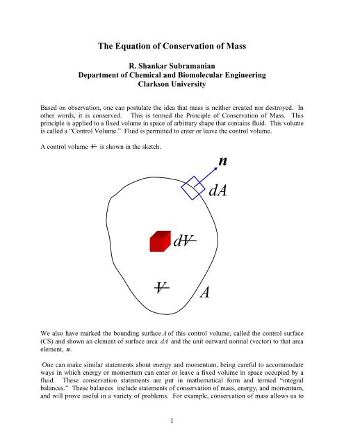
estimate the rate <strong>of</strong> change <strong>of</strong> the level <strong>of</strong> liquid in a process vessel or the rate at which theamount <strong>of</strong> gas left in a tank decreases due to leakage. <strong>Conservation</strong> <strong>of</strong> mass and energy allow usto size pumps and turbines, and help in the evaluation <strong>of</strong> flow rates using flow measurementdevices. <strong>Conservation</strong> <strong>of</strong> momentum is used in calculating the forces on the supports used forpipe bends and the forces flange bolts need to withstand. Also, by using these balances together,one can calculate the losses in a sudden expansion, design a jet ejector, and make calculationsinvolving pipe manifolds.Now, we shall proceed to express the idea that the total mass in the control volume that is shownon page 1 is conserved.Rate <strong>of</strong> increase <strong>of</strong> mass <strong>of</strong> material within the control volume = Net rate at which materialenters the control volume.Let us write a mathematical representation <strong>of</strong> the above statement. If we designate the total mass<strong>of</strong> material in the control volume as M and the net rate <strong>of</strong> entry <strong>of</strong> mass into the control volumeas m , conservation <strong>of</strong> mass can be written asdMdt= m (1)Now, we need to work out suitable results for the left and right sides <strong>of</strong> the above equation. Ifwe consider a differential volume dV , the mass <strong>of</strong> fluid in that volume is obtained bymultiplying the volume by the local density at that point ρ . By adding up all the differentialvolumes within the total volume V , we can obtain the total mass <strong>of</strong> fluid M . Therefore, wecan writeM= ∫ ρ dV(2)VThe time rate <strong>of</strong> change <strong>of</strong> this mass is then dM dt. Therefore,dMdtd= ρ dVdt∫ (3)VNow, we need to develop a result for the net rate <strong>of</strong> entry <strong>of</strong> fluid into the control volumethrough the control surface. For this, we consider the differential area element dA . If thevelocity vector is V , the component <strong>of</strong> this velocity that is directed into the control volume isgiven by − V • n , because the unit normal vector n points outward from the control volume.This result, multiplied by the area <strong>of</strong> the element dA , gives the volumetric rate at which fluidenters the control volume through this area element, labeled dQ .2
Here is an example <strong>of</strong> how we may use this statement <strong>of</strong> “<strong>Conservation</strong> <strong>of</strong> <strong>Mass</strong>” at steady state.A fluid is in steady flow through a pipe <strong>of</strong> changing cross-section as shown in the sketch., V,Aρ , V , Aρ1 1 12 2 2n 1n 2Location 1 is at the inlet and location 2 is at the outlet. Assume the velocity pr<strong>of</strong>iles are flat.The control volume is indicated by the dashed boundary. It is shown as being slightly separatedfrom the physical boundary only for clarity. In reality, its surface coincides with the physicalsurface <strong>of</strong> the pipe. Note that there is no flow through most <strong>of</strong> the control surface, that is,V • n =0 . There is flow only at the inlet (1) and exit (2). At the inlet surface the velocity pointsin a direction opposite to that <strong>of</strong> the normal vector. Therefore, V • n becomes − V1. In a likemanner, at the exit surface, the velocity points in the same direction as the normal vector whichleads to V • n becoming V2. Because V1and V2are assumed to be constant across thesurfaces involved, the integrals are easy to evaluate and we get− ρVA+ ρ VA = (9)1 1 1 2 2 20orρVA= ρ VA(10)1 1 1 2 2 2The product <strong>of</strong> the uniform velocity and the area is the volumetric flow rate Q . Therefore, wecan rewrite this asρQ= ρ Q(11)1 1 2 24
The mass flow rate m = ρ Q so that m = m1 = m 2is constant. If the density is constant, the aboverelationship reduces to Q1 = Q2. This assumption <strong>of</strong> constant density is known as theassumption <strong>of</strong> “incompressible flow.” Even though the concept <strong>of</strong> incompressibility refers tochanges in density associated with pressure changes, the term is used loosely to signify “constantdensity.”In isothermal single-component liquids, the assumption <strong>of</strong> constant density is nearly always anexcellent one to make. In the case <strong>of</strong> gases flowing at velocities that are small compared withthe speed <strong>of</strong> sound in the gas, it continues to be a good assumption. When density changes in afluid caused by pressure, temperature, or composition variations are significant when comparedwith the average density, a precise calculation must accommodate such density variations.Accommodating Velocity Variation Across the Cross-SectionIn the simplification <strong>of</strong> the principle <strong>of</strong> conservation <strong>of</strong> mass, we assumed the velocity pr<strong>of</strong>ile tobe flat at the inlet and the exit. Realistically, the velocity <strong>of</strong> a fluid satisfies the no-slip conditionat a solid boundary, and varies across the cross-section. This variation <strong>of</strong> velocity can be easilyaccommodated by using an average velocity Vavin Equations (9) and (10). The averagevelocity across the cross-section is defined as follows.Vav∫V • ndAQA1= = = • dAAA∫V n (12)AdA∫AIn Equation (12), the cross-sectional area A is oriented normal to the direction <strong>of</strong> flow, and n isa unit normal to the area in the direction <strong>of</strong> flow. The symbol dA stands for a differential areaV relement. As an example, for a circular tube <strong>of</strong> radius R , in which the velocity distribution ( )is symmetric about the tube axis, the cross-section and differential area dA = 2πrdr areillustrated in the sketch below.RrdrRing <strong>of</strong> area dA = 2πrdr5
Applying the definition given in Equation (12) yieldsRQ 1 2V = av2πrV ( r) dr rV ( r)drπR = πR = R2 2 20 0R∫ ∫ (13)Two example problems are considered next. The first example involves using the steady version<strong>of</strong> the equation <strong>of</strong> conservation <strong>of</strong> mass to make calculations involving a natural gas pipeline(source: Fluid Mechanics for Chemical Engineers by Noel de Nevers). The second exampleshows how to use the unsteady version <strong>of</strong> the equation <strong>of</strong> conservation <strong>of</strong> mass to calculate therate <strong>of</strong> change <strong>of</strong> the height <strong>of</strong> liquid in a tank.Example 1 -- Natural Gas PipelineD1 = 2.00 ftD2 = 2.50V1 = 33.7 ft / sV2= ?ft1 2p1 = 820 psiap2 = 450 psiaT1 = 70 FT2 = 58 FGas Constant R = 10.73g( f/ )2 3lb in • ftMolecular Weight = 16• R( lb mole)lblb moleFind m, V2 2This is a long pipeline, which is shown schematically. The natural gas flows through a section <strong>of</strong>circular pipe <strong>of</strong> diameter 2.00 feet for some distance, and then through a larger section <strong>of</strong> circularpipe <strong>of</strong> diameter 2.50 feet. The pressure and temperature at locations 1 and 2 are specified. Weneed to find the velocity at location 2, and the mass flow rate at location 2.6
π πA ( ) 21= D1 = × 2.00 ft = 3.14 ft4 42 2A π π( ) 22= D2 = × 2.50 ft = 4.91 ft4 42 2Let us find the mass flow rate.⎛ lb ⎞ ⎛ ft ⎞2 lbm2 = m = m1= ρ1V 1A1 = 2.31⎜ 33.7 3.143 ⎟× ⎜ ⎟× ( ft ) = 244⎝ ft ⎠ ⎝ s ⎠sNow, we can calculate the velocity V2fromV( lb s)m244 /= = =22ρ2A21.30 /34.912( lb ft ) × ( ft )38.2ftsExample 2 – Unsteady <strong>Mass</strong> BalanceDia D=2 m1V1 = 1.5 m/sD = cm15Free surfacehV2 = 1.0 m/sD = cm282Is the liquid level in the above tank rising or falling? How fast?To solve this problem, we must use the unsteady version <strong>of</strong> the conservation <strong>of</strong> mass equationapplied to a control volume that is shown in the sketch using a dashed line. The control volumeoccupies the entire interior <strong>of</strong> the tank, including the inlet and exit pipes. There is an entrance tothe control volume at location 1 and an exit at location 2. Liquid flows into the tank at location 1and flows out at location 2, as shown in the sketch.8
We begin withdMdtCS( )= − ∫ ρ V • nwhere M ( t ) is the mass <strong>of</strong> the liquid in the control volume, which depends on time t . Thedensity <strong>of</strong> the liquid ρ can be assumed to be constant.We can write the mass content in the control volume as the sum <strong>of</strong> the mass <strong>of</strong> the liquid in the2tank, given by ( π /4) ρ Dht ( ) , and the constant mass in the inlet and outlet pipe sections thatare contained the control volume, termed C . The integral on the right side <strong>of</strong> the unsteady massconservation equation works out to ρ ( Q1 − Q2). Using this information, the unsteady massconservation equation becomesdAd ⎛π⎞ π dh⎜ ρ ⎟ ρ ρdt ⎝ 4 ⎠ 4 dt( )2 2Dh+ C = D = Q1 −Q2ordhdt=( − )4 Q Q1 22π DTherefore, we must calculate the numerical value <strong>of</strong> the right side in the above equation. Theareas <strong>of</strong> the inlet and outlet can be calculated as follows.π π( ) 2−A1 = D1 = × 0.05 m = 1.96 × 10⁴ 4mπ π( ) 2−A2 = D2 = × 0.08 m = 5.03 × 10⁴ 4m2 3 22 3 2Therefore, the volumetric flow rates are⎛m⎞−Q1 = VA1 1= 1.5 ⎜ ⎟× 1.96 × 10 ( m ) = 2.94 × 10⎝ s ⎠3 2 −3⎛m⎞Q2 = VA2 2= 1.0 ⎜ ⎟× 5.03× 10 ( m)= 5.03×10⎝ s ⎠−3 2 −3Substitute the above information in the differential equation for the height <strong>of</strong> the liquid in thetank.−−( Q − Q ) ( × − × )3 3 3dh 44 2.94 10 5.03 10 m / s1 2 −4m= = = − 6.66 × 10²²dt π D πs( 2.0 m)ms3ms39
Because the rate <strong>of</strong> change <strong>of</strong> the height <strong>of</strong> liquid in the tank is negative, the liquid level isfalling.10


